The Potential for Graphite Oxidation in Dry Wall ICF Chambers
15
The Potential for Graphite Oxidation in Dry Wall ICF Chambers El S. Mogahed, I. N Sviatoslavsky, J. G. Murphy, H. Y. Khater, M. H. Anderson, and G. L. Kulcinski Fusion Technology Institute University of Wisconsin May 31, 2001
description
The Potential for Graphite Oxidation in Dry Wall ICF Chambers. El S. Mogahed, I. N Sviatoslavsky, J. G. Murphy, H. Y. Khater, M. H. Anderson, and G. L. Kulcinski Fusion Technology Institute University of Wisconsin May 31, 2001. Outline of Presentation. Why are we concerned? - PowerPoint PPT Presentation
Transcript of The Potential for Graphite Oxidation in Dry Wall ICF Chambers

The Potential for Graphite Oxidation in Dry Wall ICF
Chambers
El S. Mogahed, I. N Sviatoslavsky, J. G. Murphy, H. Y. Khater, M. H. Anderson, and
G. L. Kulcinski
Fusion Technology Institute University of Wisconsin
May 31, 2001
Outline of Presentation• Why are we concerned?• Fundamental assumptions and model of worst accident • Time dependent temperature of graphite first wall after
accident (without oxidation)• Time dependent availability of oxygen in the chamber • Potential first wall carbon oxidation rates• Time dependent temperature of graphite first wall after
accident (with oxidation)• Calculated erosion rates (with oxidation)• Methods to mitigate carbon oxidation• Conclusions and recommendations

3
Why are we concerned about possible oxidation of dry wall graphite structures?
• Woven graphite structures run at 800 to 1500 °C in a 0.5 torr Xe atmosphere in SOMBRERO.
• The introduction of air as a result of an accident could release radioactive tritium and result in structural degradation if oxidation were to take place.
• The fundamental question is “ Will the graphite first wall temperature be high enough, when the oxygen reaches it, to cause significant oxidation?”

4
Worst Accident Scenario• A 1 m2 hole is introduced in the 1.3 m thick outer building wall
while the reactor is operating.• The air rushes through the 1 m2 opening and through the laser
ports in the outer chamber, and finally through the beam ports in the inner chamber.
• The reactor and all mechanical equipment shuts down and the Li2O coolant drains from the chamber and upper manifold by gravity.
• The first wall radiates heat to the rest of the chamber and it also loses heat out the back of the blanket and shield.
• The ultimate heat sink is the wall of the outer building

5
Model of SOMBRERO Building as it is used in the MELCOR code
1 m2 HoleAtmospheric
PressureOUTER BUILDING INNER
BUILDING CHAMBER9.54 m2 Hole
2.28 m2 Hole
60 x 0.159 m2
VOLUME = 9x10⁵ m3
SOMBRERO BUILDING
60 x 0.038 m2
AtmosphericPressure
1 m2
HoleOUTER BUILDING OUTER BUILDING
INNERBUILDING
VOLUME = 1.73x10³ m3
CHAMBER
VOLUME = 2.6x10⁴ m3
50m 15m
10 m

6
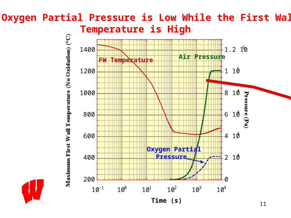
-The pressure in the chamber increases with time and reaches one atmosphere in about 4000 s (1.1 Hr) (MELCOR Calculations).
Air Pressure History in SOMBRERO Chamber After the Accident
0
2
4
6
8
10
12
0 1 2 3 4 5
Pressure In the Chamber Time History
Pres
sure
(104 P
a)
Time (103 s)
Atmospheric Pressure
Air Pressure
- The oxygen partial pressure follows same build-up pattern if there is no oxidation.
Maximum O2
Partial Pressure
(No Oxidation )

7
SOMBRERO Finite Element Thermal ModelAssumptions:
Axi-symmetric model. Transient solution,that allows conduction, convection, and radiation heat transfer that varies with time. Back of chamber radiates to the inner building wall that is initially at 350°C. The back of the inner building wall radiates to the outer building wall at 20°C.

8
• Assumptions:
Cooling due to Li22O drainage during the first 130 s after the accident
Only conduction and radiation heat transfer are in force after 130 s.
Midplane
Max.
Min.
SOMBRERO CHAMBER
Transient Thermal Analysis of SOMBRERO First Wall With No Oxidation Li2O, T= 550 °C

9
• Assumptions:
Cooling due to Li22O drainage during the first 130 s after the accident
Only conduction and radiation heat transfer are in force after 130 s.
Transient Thermal Analysis of SOMBRERO First Wall With No Oxidation
600
700
800
900
1000
1100
1200
1300
1400
1500Temperature History of SOMBRERO FW
Max. (°C)Midplane (C°)Min. (C°)
0.1 1 10 100 1000
SOMBRERO FW Temperature (°C)
Time (s)
Midplane
Max.
Min.
SOMBRERO CHAMBER
Maximum Initial Temp. = 1450°C
•Conduction•Radiation
•Convection Cooling•Conduction•Radiation
TemperatureEqualization

10
Cooling due to Li22O Drainage During the First 130 s After the Accident.
Only Conduction and Radiation Heat Transfer is in effect after 130 s.
- The Back of the Chamber Remains Hot (≈ 780°C) During the First 130 s.
Transient Thermal Analysis of SOMBRERO FW/Chamber With No Oxidation
200
400
600
800
1000
1200
1400
10-1 100 101 102 103 104 105 106 107
Max
imum
Fir
st W
all T
empe
ratu
re (°
C)
Time (s)
Midplane
Max.
Min.
SOMBRERO CHAMBER
130
s
1 D
ay
1 M
onth
Max.
Mid.
Min.
Cooling Due toLi
2O Drainage
11
200
400
600
800
1000
1200
1400
0
2 104
4 104
6 104
8 104
1 105
1.2 105
10-1 100 101 102 103 104
Maximum First Wall Temperature (No Oxidation) (°C) Pressure (Pa)
Time (s)
FW Temperature Air Pressure
Oxygen PartialPressure
The Oxygen Partial Pressure is Low While the First WallTemperature is High

12
10 -9
10 -8
10 -7
10 -6
10 -5
10 -4
10 -3
200 400 600 800 1000
Oxidation Rate (g/cm
2s)
First Wall Maximum Temperature (°C)
Union Carbide (CIT)
GraphNOL N3M
1500
ExperimentalDataExtrapolation
Union Carbide (CIT)
GraphNOL N3MPfizer Pyrolytic
ExperimentalDataExtrapolation
0
5 10 5
1 10 6
1.5 106
2 10 6
2.5 106
3 10 6
Time (s)
Union Carbide (CIT)
GraphNOL N3M
1 Month
One Day
One Week
Pfizer Pyrolytic
ExperimentalDataExtrapolation
FW Max.Temperature
Different Graphites Have Very Different Oxidation Rates
Experimental data is available for temperatures over 800°C.
- Union Carbide graphite oxidation rate is two times higher than GraphNOL N3M.- Pfizer pyrolytic graphite oxidation rate is much less than both Union Carbide Graphite and GraphNOL N3M.

13
The Choice of the Wrong Graphite for an IFE First Wall Could Cause Problems if The Building is Breached
200
400
600
800
1000
1200
1400
1600
10-3
10-2
10-1
100
101
102
103
104
10-1 100 101 102 103 104 105 106 107
Maximum First Wall Temperature (°C) Oxidation thickness( cm)
Time (s)
Temp. of FWwithout Oxidation
Temp. of GraphNOL N3Mwith Oxidation
• FW graphite temperature rises as a result of exothermic reaction with oxygen.
Temp. of Pfizer Pyrolyticwith Oxidation
Oxidation thickness(Pfizer Pyrolytic)
• Oxidation of pyrolytic graphite is very low and raises FW temperature about 10°C at most.
Oxidation thicknessGraphNOL N3M
• Oxidation of GraphNOL graphite is very rapid, it will oxidize the 1 cm FW in about 3.5 Hr.

14
Methods of Mitigating Air Ingress Accident Effect
• Shutters on chamber beam-ports triggered by pressure imbalance
• Reduce inner building wall temperature• SiC coating everywhere except first wall• Thin (≈ 30 ) SiC undercoating on the first wall• Flood chamber with CO2
• Plug hole in building!

15
Conclusions• The survival of the graphite first wall, in the event of
an unlikely ingress of air, is critically dependent on the type of graphite used.
• If the wrong type of graphite is chosen, the first wall could be completely oxidized in a few hours
• If pyrolytic, or H-451 graphite is chosen, there should be little oxidation (even after a few months)
• An experiment is needed to measure oxidation rates at reduced oxygen levels and at 200<T< 800 °C.


![Chemical synthesis through oxidation of graphite[9-9]](https://static.fdocuments.in/doc/165x107/56814839550346895db55764/chemical-synthesis-through-oxidation-of-graphite9-9.jpg)


![Oxidation resistance and wettability of graphite/SiC compositeeprints.whiterose.ac.uk/137817/3/C.F.Yin and X.C.Li-22...Mukhopadhyay et al. [14-15] synthesized calcium aluminate (CaAl2O4)](https://static.fdocuments.in/doc/165x107/60a42011f1101b72d65224ed/oxidation-resistance-and-wettability-of-graphitesic-and-xcli-22-mukhopadhyay.jpg)