The Pig Pen - N5DUXn5dux.com/ham/pubs/flyingpigs/BB1000.pdfBacon Bits Newsletter from the Flying...
12
Bacon Bits Newsletter from the Flying Pigs QRP Club, International October, 2000 - 1 - Bacon Bits Flying Pigs QRP Club International, W8PIG 1900 Pittsfield St, Kettering, Ohio 45420 E-mail: [email protected] Web Page: http://www.fpqrp.com FPQRP membership is open to all licensed QRP operators who reside within 12,000 nautical miles of Cincinnati, Ohio. CONTACTS: Diz, W8DIZ [email protected] Rick, WB6JBM [email protected] Dan, N8IE [email protected] NETS: DAY TIME FREQ Sat 1400Z 14062 Sun 1300Z 7044 Sun 1400Z 14062 Thurs 0200Z 7044 CLUB FREQS. 1,814 kHz 3,564 kHz 7,044 kHz 10,110 kHz 14,062 kHz 18,100 kHz 21,064 kHz 24,910 kHz 28,064 kHz ALL FPqrp frequencies are UP 4 kHz from the standard qrp frequencies except for 20 meters. In this issue: Number 1 was a hit! Page 2 Website Spotlight. Page 2 From Zepplins to FET’s. Page 2 A 40 Meter Vertical. By Gray, NS8O Page 2 Capacitive Switch Paddles. By Rick, WB6JBM Page 4 A different approach to placing wire antennas in trees. By Bob, K8YS Page 5 Multiple Bands, One antenna! Which feedline do I use? By Rick, KC8AON Page 7 Basic Stamp Application to Control Your Homebrew Receiver, Part 1 By Mike, WB8ICN Page 8 The miniPIG the multiPIG and the "UGLY" By Diz, W8DIZ Page 10 Changes for the e-mail reflector By Rick, WB6JBm Page 11 Member Spotlight Page 12 Info about the Flying Pigs. Page 12
Transcript of The Pig Pen - N5DUXn5dux.com/ham/pubs/flyingpigs/BB1000.pdfBacon Bits Newsletter from the Flying...
Bacon Bits Newsletter from the Flying Pigs QRP Club, International October, 2000
- 1 -
Bacon BitsFlying Pigs QRP Club International, W8PIG
1900 Pittsfield St, Kettering, Ohio 45420E-mail: [email protected] Web Page: http://www.fpqrp.com
FPQRP membership is open to all licensed QRP operators who reside within 12,000 nautical miles of Cincinnati, Ohio.
CONTACTS:Diz, W8DIZ [email protected], WB6JBM [email protected], N8IE [email protected]
NETS:DAY TIME FREQSat 1400Z 14062Sun 1300Z 7044Sun 1400Z 14062Thurs 0200Z 7044
CLUB FREQS.1,814 kHz 3,564 kHz7,044 kHz 10,110 kHz14,062 kHz 18,100 kHz21,064 kHz 24,910 kHz28,064 kHz
ALL FPqrp frequencies are UP 4 kHzfrom the standard qrp frequencies
except for 20 meters.
In this issue:
Number 1 was a hit! Page 2Website Spotlight. Page 2From Zepplins to FET’s. Page 2A 40 Meter Vertical. By Gray, NS8O Page 2Capacitive Switch Paddles. By Rick, WB6JBM Page 4A different approach to placing wire antennas in trees. By Bob, K8YS Page 5Multiple Bands, One antenna! Which feedline do I use? By Rick, KC8AON Page 7Basic Stamp Application to Control Your Homebrew Receiver, Part 1 By Mike, WB8ICN Page 8The miniPIG the multiPIG and the "UGLY" By Diz, W8DIZ Page 10Changes for the e-mail reflector By Rick, WB6JBm Page 11Member Spotlight Page 12Info about the Flying Pigs. Page 12

Bacon Bits Newsletter from the Flying Pigs QRP Club, International October, 2000
- 2 -
Number 1 was a hit!By Dan, N8IE
Hello, and welcome to the second issue of the Bacon Bitsnewsletter. I want to take this time to thank all the wonderfulpeople who sent in articles, and wrote us letters last month.Your response to the first issue is greatly appreciated, and wehope we can build on this.
This month we have a real treat, Diz, W8DIZ starts his series onthe MiniPig, and the MultiPig radios. This will be of interest toall since it covers a lot of theory, and Manhattan styleconstruction. Also we have a nice article on a 40M vertical byGary, N8SO, plus a lot more goodies! Enjoy.
Website Spotlight.
This month’s spotlight deals with basic electronics.If you’re new to Ham Radio or you’ve been around since beforethere were callsigns, basic electronics is the foundation whichHam Radio is built upon. Without it, we would still be on hilltops pounding sticks together to send messages. !So with out further adieu, let’s surf!
The first site on our tour is http://www.basicelectronics.comHere you will find a nicely done interface covering electronicprinciples, this includes Ohm's Law, Circuit Theory, etc.
One of our very own, Ian Purdie, VK2TIP (Fp#-91) has awonderful sight, http://www.electronics-tutorials.com/Offering comprehensive basic electronics tutorials inamplifiers, ham radio, filters, oscillators, power supply,receivers, transmitters, radio design, and electronics design.
The Electronics Workshop athttp://library.thinkquest.org/10784/Is an introduction to electronics, with tutorials givingimportant physics and chemistry concepts related to the fieldof electronics.
Graham Knott has a very nice site athttp://ourworld.compuserve.com/homepages/g_knott/It offers electronics for beginners and intermediate level aswell.
Iguana Labs athttp://www.proaxis.com/~iguanalabs/maintut.htmhas a nice site that offers tutorials and kits for the beginner toadvanced levels.
I hope these sites will be of use to you all, now get out thereand melt solder!
73, ooDan, N8IE
From Zepplins to FET’s
Dr. Julius Edgar Lilienfeld was a German scientist whoworked at the University of Leipzig before immigrating tothe U.S. in the 1920's. Lilienfeld operated the first large-scale hydrogen liquefaction facility in Germany. The liquidproduct was used to fill Zepplins and for cryogenic research.He obtained a U.S. patent on the cryogenic separation ofgases in 1915. Lilienfeld developed and patented several X-ray tubes around 1920, which placed him in direct conflictwith Coolidge at G.E. (an excellent piece on the X-ray tubedevelopment has been published by Prof. Robert G. Arns,University of Vermont in Burlington)
During 1925-1928, Lilienfeld developed and patentedseveral devices that would now be referred to as field effector point junction transistors. Shockly's original field effecttransistor patent was completely thrown out and Bardeen'spoint junction patent transistor patent had over half theclaims dismissed due to Lilienfeld's prior work. Some of theconstructions shown in the patents have been reproduced byProf. Arns and a grad student, Bret Crawford, at U.Vermont,Burlington, and by Prof. Joel Ross, St. Michael's College,Vermont. While the devices did not perform to today'sstandards, signal amplification was detected. The exactconstruction employed and performance obtained byLilienfeld remain unknown.
A 40 Meter VerticalBy Gary, NS8O
Ham radio is such a great hobby, you just never stoplearning and enjoying the fascination that comes with it.Sometimes the learning comes with a lot of trips up the ol'antenna tower...
Take my latest antenna adventure for example. I wanted toget on 40 meters with a better 'tenna for this fall/wintercontest season. I have used dipoles, slopers, etc. but theyjust weren't as effective as I wanted.They had to hang well below my HF tribander, which I'msure doesn't help. I don't have room for any kind of beam orphased arrays, but I do have space to go up. A quarterwave40-meter vertical on the top of my 50' tower (with HFbeam) should do wonders... So I TIG welded somealuminum tubing together to make a 33' high self-standing40 meter vertical. I actually made it into 2 sections so it waseasy to work with. Diameter starts from 1 1/8" at thebottom, to the top 6 feet, which is a very lightweight TVantenna element.
I mounted the antenna in a bracket that insulates it, so I canfeed it direct with coax. I couldn't get it to the topof the mast, because of the 6-meter beam I have there, so Imounted it a few feet from the top.
Bacon Bits Newsletter from the Flying Pigs QRP Club, International October, 2000
- 3 -
The coax RG 8/U feeds it directly and is grounded at thebracket with the SO-239 connector.
NOW it is education time...I hooked up some test gear expecting the thing to be right onresonance at 7.1 MHz or so. The resonant frequencyof the 33-foot antenna went to 7.5 MHz! I couldn't figure outwhat had happened; I had double-checked everymeasurement.
To make a long story short, the mast/antenna relationship hadbecome a transmission line, a balanced one consisting of theantenna element and the mast, being in such close proximityof each other; within 3 inches. So the length parallel to themast was not radiating! The effective height of the antennawas what was above the mast; approximately 31.2 feet.
To test this theory, I moved the antenna up as high on themast as I could and then checked the resonance frequency; ithad gone to down to 7.4 MHz. My theory seemed to be true.The only solution was to take theantenna down, add two more feet to it and then see whathappens.
Sure enough, after adding two feet to the top, remounting theantenna the resonance freq. went down! (Imagine me at thetop of the tower, lifting up a 35' antenna into the bracket,which uses two U bolts to attach it to the mast. Then imaginethe fun when one of the U-bolts broke... but that is anotherstory. The moment of truth had arrived... what is theresonance freq. and SWR? Freq. is 7.15 and the SWR is lessthat 1.2 to 1 across the band, 1:1 at 7.15 MHz.
So lesson learned? A vertical antenna mounted close to a mastactually becomes a balanced transmission line,effectively making the antenna only as long as what is abovethe mast. So remember this if you are going make a verticaland save yourself a few trips up the tower!
Antenna works great, worked UU4, F6 on 40meters with noproblems. I also feed it on other bands via a tuner. Checkedinto the WQ1RP 80 meter net last night with 5 watts and got a579. (I feed the coax braid on 80 and 160; a gamma matchtype arrangement to feed the entire tower/antenna)
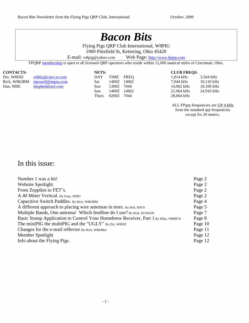
Close view of the mounting bracket for the antenna. Thebracket is grounded to the mast but the antenna is insulatedfrom the bracket.
In this view you can see the bracket that supports the 40-meter vertical. It is held on the mast by 2 U-bolts.Loosening these bolts up allowed me to slide the 40-metervertical up and down the mast. It is about as far up as I canget it now.
Bacon Bits Newsletter from the Flying Pigs QRP Club, International October, 2000
- 4 -
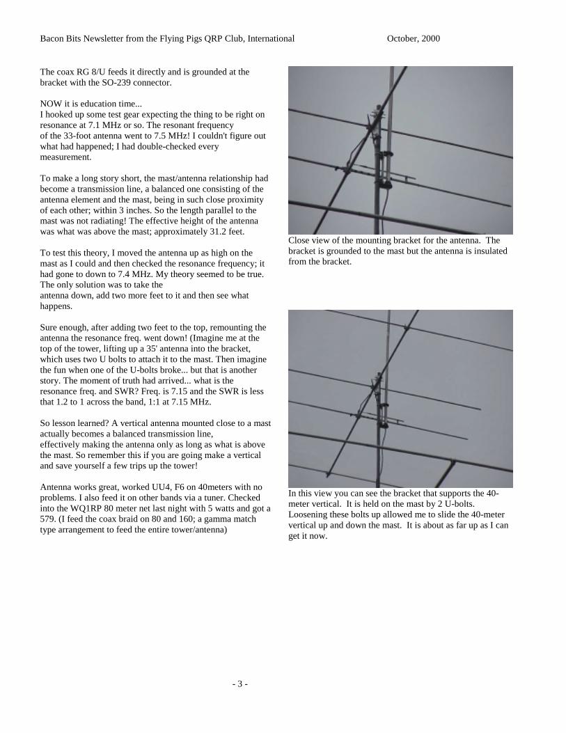
In the whole antenna view, you can see the 35' element on topof the mast. Just below it is the 6-meter beam and below thatis the HF tribander.
72 de NS8O
Capacitive Switch PaddlesAKA KP KitBy Rick, WB6JBM
The KapacitivePaddles project started as a desire toconsolidate 'boxes' by Diz, W8DIZ after building his K2. Thedesign is loosely based on a capacitive touch switch from anout of production Programmable Drum Set. The origin of thecircuit can be traced to http://paia.com/touchsw.htm
Modifications to the circuit included switching to a 4011,quad-dual input NAND gate, some capacitor value mods tospeed the response time, and elimination of the latch circuit.
Addition of support for the K10 keyer was based directly oncircuits listed by K1EL http://members.aol.com/k1el/
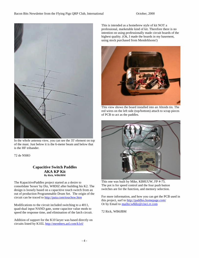
This is intended as a homebrew style of kit NOT aprofessional, marketable kind of kit. Therefore there is nointention on using professionally made circuit boards of thehighest quality. (Ok, I made the boards in my basement,using stock purchased from Mendehlsons!)
This view shows the board installed into an Altoids tin. Thered wires on the left side (top/bottom) attach to scrap piecesof PCB to act as the paddles.
This one was built by Mike, KB8UUW, FP #-75.The pot is for speed control and the four push buttonswitches are for the function, and memory selection.
For more information, and how you can get the PCB used inthis project, surf to http://paddles.homepage.com/Or by Email to mailto:[email protected]
72 Rick, WB6JBM
Bacon Bits Newsletter from the Flying Pigs QRP Club, International October, 2000
- 5 -
A different approach to placing wire antennas intrees.
Bob K8YS
Seeing a need to hang wires in tree, over tall building orwhere ever that is some times difficult to reach, I investigatedthe “wrist rocket” type launcher. Well, I like things that arepropelled by controlled explosion. So I made a launcher thatis made from common parts found at any Sears, Home Depot,or most well stocked workshops... especially if you are likeme and hate to throw anything away.
The K8YS Long wire Launcher is a “spud gun” and a Zebco202 fishing reel.
As a kid, I had toys that used calcium carbide and then theinfamous tennis ball cannon. When was the last time you sawa beer can that needed to be opened with a can opener?1967??
Well, finding the cans was out, so I heard about the “spudgun” or “taterzooka” (or as a smaller caliber, a “squirrel-zooka” for them pesky tree rats). Then I was struck with“HEY what an idea!”, I’ll build a spud gun and launch a plugwith a string attached to retrieve the wire, so the K8YS Longwire Launcher was born.
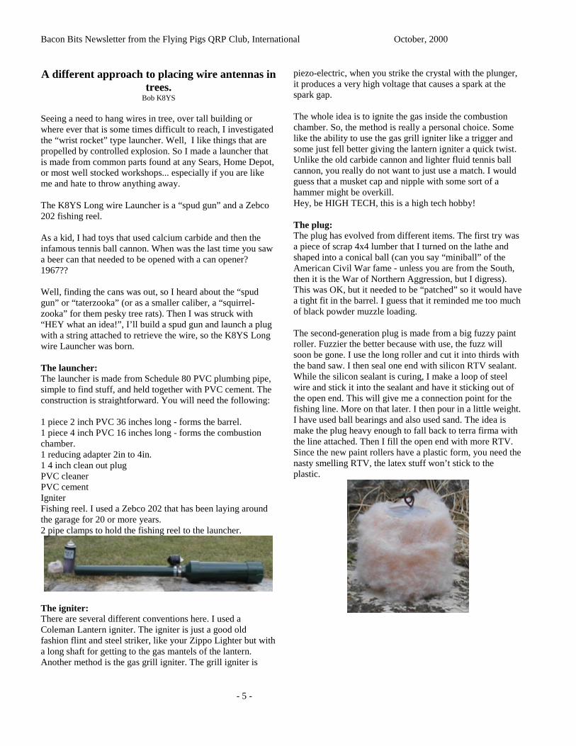
The launcher:The launcher is made from Schedule 80 PVC plumbing pipe,simple to find stuff, and held together with PVC cement. Theconstruction is straightforward. You will need the following:
1 piece 2 inch PVC 36 inches long - forms the barrel.1 piece 4 inch PVC 16 inches long - forms the combustionchamber.1 reducing adapter 2in to 4in.1 4 inch clean out plugPVC cleanerPVC cementIgniterFishing reel. I used a Zebco 202 that has been laying aroundthe garage for 20 or more years.2 pipe clamps to hold the fishing reel to the launcher.
The igniter:There are several different conventions here. I used aColeman Lantern igniter. The igniter is just a good oldfashion flint and steel striker, like your Zippo Lighter but witha long shaft for getting to the gas mantels of the lantern.Another method is the gas grill igniter. The grill igniter is
piezo-electric, when you strike the crystal with the plunger,it produces a very high voltage that causes a spark at thespark gap.
The whole idea is to ignite the gas inside the combustionchamber. So, the method is really a personal choice. Somelike the ability to use the gas grill igniter like a trigger andsome just fell better giving the lantern igniter a quick twist.Unlike the old carbide cannon and lighter fluid tennis ballcannon, you really do not want to just use a match. I wouldguess that a musket cap and nipple with some sort of ahammer might be overkill.Hey, be HIGH TECH, this is a high tech hobby!
The plug:The plug has evolved from different items. The first try wasa piece of scrap 4x4 lumber that I turned on the lathe andshaped into a conical ball (can you say “miniball” of theAmerican Civil War fame - unless you are from the South,then it is the War of Northern Aggression, but I digress).This was OK, but it needed to be “patched” so it would havea tight fit in the barrel. I guess that it reminded me too muchof black powder muzzle loading.
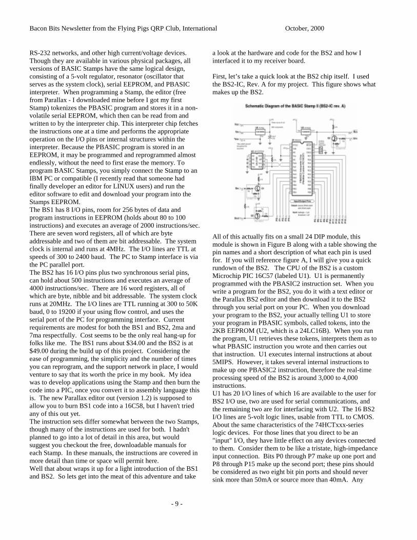
The second-generation plug is made from a big fuzzy paintroller. Fuzzier the better because with use, the fuzz willsoon be gone. I use the long roller and cut it into thirds withthe band saw. I then seal one end with silicon RTV sealant.While the silicon sealant is curing, I make a loop of steelwire and stick it into the sealant and have it sticking out ofthe open end. This will give me a connection point for thefishing line. More on that later. I then pour in a little weight.I have used ball bearings and also used sand. The idea ismake the plug heavy enough to fall back to terra firma withthe line attached. Then I fill the open end with more RTV.Since the new paint rollers have a plastic form, you need thenasty smelling RTV, the latex stuff won’t stick to theplastic.

Bacon Bits Newsletter from the Flying Pigs QRP Club, International October, 2000
- 6 -
Fuel:Fuel is simple stuff. The most common fuel is hair spray, thecheaper the better. White Rain brand is the favorite. I oftenwonder if women know what they are putting in their hair.NASTY STUFF. I have also tried ether based starter fluid, butit is slow burning. I have been told that the OLD WD-40works very well, better than hair spray, but the new stuff usesCO2 for the propellant. There are web sites that have otherplans for using butane and propane but the hair spray is easy,cheap, and you can find it at home. WD-40 won’t gum up thecombustion chamber.
Construction:First thing to do is to bevel one end of the 2 inch PVC. Thereason for this is that if for some reason, you have theuncontrolled urge to launch a potato, the beveled end makesinsertion of the semi round potato easier into the round pieceof PVC. The beveled end acts like a knife.
Clean the square end of the 2-inch pipe with PVC cleaner.Clean the 2-inch end of the adapter with the cleaner. Aftercleaner dries, test fit the two. No need to glue just yet. Cleanboth ends of the 4-inch piece as well as the clean out plugsleeve and the inside of the 4-inch end of the adapter. Again,test fit everything. Just be careful not to get cleaner or cementon the screw threads of the clean out plug. Cleaning does helpthe cement bond better. While this will not be under 100pounds per square inch water pressure, it must contain theexploding gasses.
Depending on what igniter you use, mount the ignitor. I usedthe Coleman Lantern igniter. I then drilled a hole in the cleanout plug cap and mounted the igniter with the striker on theinside and the twist knob on the outside.
If you like the gas grill type, you can mount is in the captoo, or on the side of the combustion chamber. Since I havenot used the gas grill type, I would think that it would be agood idea to epoxy the thing in place.
Now would be a good time to glue everything together.Plumbers tell me that they apply the cement to the piecesthen give them a twist until the cement is cured. I guess theydo this to make sure that glue got all the way around theconnection.
Testing and Use:To test the launcher, I use a heavy rag, a couple shop ragswadded up or a old towel. Stuff the rag down the muzzle tothe top of the combustion chamber. Remove the clean outplug, give the hair spray a squirt. Just a couple of seconds isall it takes, then QUICKLY screw the clean out plug backinto place. Make sure the range is clear. Then aim themuzzle down range, hit the igniter and WHOOSH! The ragwill fly about 20 feet.
To use the launcher, attach the fishing reel to the barrel withthe pipe clamps. Attach the fishing line to the plug. Push theplug down the muzzle until it is just above the combustionchamber. Remove the clean out plug, give the hair spray asquirt, two seconds is good, five seconds is a bit too much...experiment. Push in the release on the fishing reel (or is youare using a spinning reel, release the catch thing), you do notwant that plug coming back at you! Aim, hit the igniter andwatch the line play out. When the plug lands, go to the farend, untie or disconnect the fishing line from the plug, tie tothe long wire and reel it in with the fishing reel.
My reel has 100 yards of line. With a 4 to 5 second charge, Ican send the plug out to the end of the line.

Bacon Bits Newsletter from the Flying Pigs QRP Club, International October, 2000
- 7 -
Refinements:Paint:Paint the long wire launcher a subdued color. Camouflage ismy favorite. Flat black, dark green etc you get the idea.
Barrel:There are web pages devoted to the spud gun. There are alsothose that manufacture a rifled barrel for the long rangeshooter.
The original plans that I found called for a longer barrel, but Ihave always like the “carbine” version of everything so mylauncher has a shorter barrel. The combustion chamber is still16 inches, but the barrel is only 24.
Caution:This is NOT a toy. Think Safety Use Safely! Youreally do not want to size a potato, then freeze it.A frozen potato has been rumored to penetrate apiece of plywood. Common sense is your besttool.
Here are a couple URL’s for the Spud Gun.http://members.primary.net/~xavier/air.htmlhttp://members.primary.net/~xavier/potato.htmlhttp://www.calisland.com/web_ring.htmhttp://www.geocities.com/Hollywood/8357/
If you must have more, follow the links on these pages. Thereis even a web ring devoted to spud guns. Some of these guysare really warped.
RAGE against the Potato.
Conclusion:
As I said before, I like controlled explosions, while a paintroller is not exactly copper jackets lead slugs, the basicprincipal is the same. It is also a little larger than my favorite.308 inch toys (big boy toys). Construction is easy and thewhole thing costs a lot less then you can buy the slingshotdevice.
72Bob, K8YS
Multiple Bands, One antenna! Which feedlinedo I use?
By Rick, KC8AON
Below are some comparisons between a 135' long dipole fedwith 50 ohm coax and 450 ohm ladder line at an averageheight of 40 feet high, and a feedline length of 50 feet oneach and using an antenna tuner on all bands above thedesign frequency. Match at transmitter is near perfect due totuner, but SWR values effects that between the tuner andantenna (this does not change when using a tuner). Theefficiency figures will show you how much difference thereis between the two feedlines.
135' dipole with 50' of RG8X 50 ohm coax @ 40'.Freq. in MHz SWR Efficiency3.5 1.4:1 72%7.0 9:1 7.2%10.1 5.5:1 22.7%14 6.5:1 6.6%18.1 3.1:1 42.7%21.0 5.3:1 6.1%24.9 1.9:1 54.8% not to bad28.0 4.6:1 5.7%
135' dipole fed with 50' of 450 ohm ladder line @ 40'.Freq. in MHz SWR Efficiency3.5 64.5:1 83.5%7.0 58.2:1 87.7%10.1 7:1 89.6%14.0 1.3:1 89% very good!18.1 4.7:1 92.8%21.0 34.8:1 89%24.9 18.8:1 91.9%28.0 67.4:1 87.9%
Notice that on the dipole fed with ladder line, that althoughthe swr values were very high in some cases, the efficiencylevels remained high, in fact, they are higher than the nearperfect match of the 50 ohm fed version at 3.5 MHz!83.5% versus 72% isn’t too shabby considering that ladderline is cheaper than coax! Only got room for one antenna?These figures should help you figure out what to use.Best 73 & don’t get on a power trip!Rick, KC8AON

Bacon Bits Newsletter from the Flying Pigs QRP Club, International October, 2000
- 8 -
Basic Stamp Application to Control Your Homebrew Receiver, Part 1
By Mike, WB8ICN
I originally wrote a lengthy article for CommunicationsQuarterly (now part of ARRL’s QEX). That article wasdivided four sections; the first described what got me startedon this interface project and what lead me to the Stamp. HowI went about gathering information and then discovered awealth of knowledge through an e-mail list for the Stamp.Second, I thought it wise to detail both the BASIC Stamp 1and 2, the editors used to write, debug and program code forthe Stamps, and how easy it is to get started with the Stamp.Third, my project - a replacement of analog controls (RF gain,Coarse and Fine Tuning, and Bandpass) on my Ten TecSSB/CW receiver board with digital pots controlled by theStamp. I explained both the hardware configuration and thecode used to make it all work. Finally, the fourth section wasa general wrap-up with some thoughts of my own on why wehams mess around with simple things like the Stamp, howhomebrewing is still an art that many of us learn from, andsome ideas for future enhancements of the interface projectand some rather exciting ideas for uses of the Stamp and itsactual processor, the PIC 16Cxx series chips. The followingis excerpts from that article with some editing to make it moreappropriate for the FP Newsletter.
Many articles have appeared featuring a new approach forhomebrewers in the quest to digitally control their respectivestations. This new approach is centered around Microchip's16C56 and 57 series microcontroller chip (uIC). These uIC'sare used in many applications including a rather unique mini-processor system on a chip called a Stamp, more precisely putthe Basic Stamp 1 (BS1) and Basic Stamp 2 (BS2). Bothchips are produced by Parallax, Inc. The BASIC Stamp is aregistered trademark of Parallax, Inc. I first discovered theseabout six years ago in random search on the Internet for asimple, yet effective, interface controller. I had heard aboutthe Stamp a few years back at the Dayton Hamvention, butsomeone told me that the Stamp was far too slow for anypractical use in ham radio. Well, a very important lesson waslearned here...always do your own research and form yourown judgments! The Stamp may be too slow for applicationssuch as a frequency counter in the RF range, but it holds it’sown when it comes to a simple interface controller I hadbought a Ten Tec CW-SSB Receiver kit, Model 1056, at the1996 Hamvention. It had been many years since I have hadthe chance to build a fun kit and this looked like a good wayto start again in hopes of getting back into the homebrew wayof life. I built the kit and had many hours of fun using it tocopy CW and SSB stations. The kit allows you the option ofwhich band to wire the local oscillator for and I chose 40meters. After awhile, the kit was pushed aside for room onthe bench for other interests. When I decided that I neededsome way to digitally control my Ten Tec receiver board so Icould control it with my PC and do some fancy digital mode
operation such as packet, SSTV, etc., I had thought it wouldbe a bright idea to order the more versatile of the twoStamps, i.e. the Stamp 2. But after playing with it for a fewdays, I discovered that most of the application notes for theStamps, at least available at that time, were for the Stamp 1.The Stamp 2 was relatively new and just starting to catch onwith more work and ideas were being brought forth andshared with others. Since I wanted to ensure the mostapplicable platform for as many users as possible - I hadgained a lot of knowledge from so many Stampersters, Iwanted to share something and this was my first real projectto share - I decide it best to rewrite Beau's code andhardware design from the Stamp 2 (this is the Stamp he alsochose for this type of application) to the Stamp 1. Thereengineering of the hardware portion was rather easy (I didthis sort of thing as a career), but the conversion of code wasa challenge for me at the time. Now that I've went bothways with it, it seems rather simple and fun...sort of like acrossword puzzle.The first project (using the Stamp 1) was completed inFebruary 1998 and posted on my web page. Only oneproblem remained after the initial work was done, and theonly real fix for it was a bandaide, which I detest usingunless its the only solution. The Stamp 1 only has 8 I/Olines not enough for what I was trying to do. I did find away to use only one I/O for the four function switchesneeded for the receiver board. The hardware used todetermine which switch I had pushed was accomplished byusing an RC network and a decision-making logic table insoftware. The problem was the RC network caused aclicking noise in the receiver that I couldn't easily mask outentirely. I did find a method of using a lot of capacitors tobasically pull all the low frequency AF (RC time constantclicking noise) to ground but didn't really care for thisapproach, i.e. the bandaide saved the patient but what amess to look at once it was done. Since I couldn't sellmyself on this solution, which meant no one else would everbuy off on it, I then rewrote the code and redid the hardwarefor the receiver board using the Stamp 2. Since the Stamp2 has twice the number of I/O lines available for use, I hadplenty of I/O lines for switches and no RC network wasneeded to determine which switch had been pushed.Versatility provided the solution by having enough I/O linesso each of the four switches had their own access to theCPU of the Stamp processor.The BASIC Stamp is nothing more than a small computer,actually a microprocessor that runs Parallax BASIC(PBASIC) programs. The PBASIC language is proprietarysoftware developed by Parallax for use in the Stamp 1 (BS1)and Stamp 2 (BS2). It is burned into the 16C56 or 57'sEPROM, depending on which Stamp your using. EachStamp has fully programmable I/O pins that can be used todirectly interface to TTL-level devices, such as buttons,LED’s, speakers, potentiometers, and shift registers. Byadding a few extra components, these I/O pins can beconnected to non-TTL devices, such as solenoids, relays,
Bacon Bits Newsletter from the Flying Pigs QRP Club, International October, 2000
- 9 -
RS-232 networks, and other high current/voltage devices.Though they are available in various physical packages, allversions of BASIC Stamps have the same logical design,consisting of a 5-volt regulator, resonator (oscillator thatserves as the system clock), serial EEPROM, and PBASICinterpreter. When programming a Stamp, the editor (freefrom Parallax - I downloaded mine before I got my firstStamp) tokenizes the PBASIC program and stores it in a non-volatile serial EEPROM, which then can be read from andwritten to by the interpreter chip. This interpreter chip fetchesthe instructions one at a time and performs the appropriateoperation on the I/O pins or internal structures within theinterpreter. Because the PBASIC program is stored in anEEPROM, it may be programmed and reprogrammed almostendlessly, without the need to first erase the memory. Toprogram BASIC Stamps, you simply connect the Stamp to anIBM PC or compatible (I recently read that someone hadfinally developer an editor for LINUX users) and run theeditor software to edit and download your program into theStamps EEPROM.The BS1 has 8 I/O pins, room for 256 bytes of data andprogram instructions in EEPROM (holds about 80 to 100instructions) and executes an average of 2000 instructions/sec.There are seven word registers, all of which are byteaddressable and two of them are bit addressable. The systemclock is internal and runs at 4MHz. The I/O lines are TTL atspeeds of 300 to 2400 baud. The PC to Stamp interface is viathe PC parallel port.The BS2 has 16 I/O pins plus two synchronous serial pins,can hold about 500 instructions and executes an average of4000 instructions/sec. There are 16 word registers, all ofwhich are byte, nibble and bit addressable. The system clockruns at 20MHz. The I/O lines are TTL running at 300 to 50Kbaud, 0 to 19200 if your using flow control, and uses theserial port of the PC for programming interface. Currentrequirements are modest for both the BS1 and BS2, 2ma and7ma respectfully. Cost seems to be the only real hang-up forfolks like me. The BS1 runs about $34.00 and the BS2 is at$49.00 during the build up of this project. Considering theease of programming, the simplicity and the number of timesyou can reprogram, and the support network in place, I wouldventure to say that its worth the price in my book. My ideawas to develop applications using the Stamp and then burn thecode into a PIC, once you convert it to assembly language thisis. The new Parallax editor out (version 1.2) is supposed toallow you to burn BS1 code into a 16C58, but I haven't triedany of this out yet.The instruction sets differ somewhat between the two Stamps,though many of the instructions are used for both. I hadn'tplanned to go into a lot of detail in this area, but wouldsuggest you checkout the free, downloadable manuals foreach Stamp. In these manuals, the instructions are covered inmore detail than time or space will permit here.Well that about wraps it up for a light introduction of the BS1and BS2. So lets get into the meat of this adventure and take
a look at the hardware and code for the BS2 and how Iinterfaced it to my receiver board.
First, let’s take a quick look at the BS2 chip itself. I usedthe BS2-IC, Rev. A for my project. This figure shows whatmakes up the BS2.
All of this actually fits on a small 24 DIP module, thismodule is shown in Figure B along with a table showing thepin names and a short description of what each pin is usedfor. If you will reference figure A, I will give you a quickrundown of the BS2. The CPU of the BS2 is a customMicrochip PIC 16C57 (labeled U1). U1 is permanentlyprogrammed with the PBASIC2 instruction set. When youwrite a program for the BS2, you do it with a text editor orthe Parallax BS2 editor and then download it to the BS2through you serial port on your PC. When you downloadyour program to the BS2, your actually telling U1 to storeyour program in PBASIC symbols, called tokens, into the2KB EEPROM (U2, which is a 24LC16B). When you runthe program, U1 retrieves these tokens, interprets them as towhat PBASIC instruction you wrote and then carries outthat instruction. U1 executes internal instructions at about5MIPS. However, it takes several internal instructions tomake up one PBASIC2 instruction, therefore the real-timeprocessing speed of the BS2 is around 3,000 to 4,000instructions.U1 has 20 I/O lines of which 16 are available to the user forBS2 I/O use, two are used for serial communications, andthe remaining two are for interfacing with U2. The 16 BS2I/O lines are 5-volt logic lines, usable from TTL to CMOS.About the same characteristics of the 74HCTxxx-serieslogic devices. For those lines that you direct to be an"input" I/O, they have little effect on any devices connectedto them. Consider them to be like a tristate, high-impedanceinput connection. Bits P0 through P7 make up one port andP8 through P15 make up the second port; these pins shouldbe considered as two eight bit pin ports and should neversink more than 50mA or source more than 40mA. Any

Bacon Bits Newsletter from the Flying Pigs QRP Club, International October, 2000
- 10 -
unused I/O pin should be made into a output pin andconnected to +5v.The only important considerations to remember about theEEPROM (U2) is that it takes several milliseconds to writedata into it; and the limitation on the number of write cyclesbefore it begins to fail is around 10 million times--you can doa lot of writes and downloads before you hit that number. U3is used as the reset circuit and rather important during power-up. For those who wish a even more detailed description ofthe BS2, I recommend that you download the BS2 manual(BASIC Stamp Programming Manual 1.8) and read pages 207through 212. But don't stop there...this can be your one-stopguide to using the BS2 including some application ideas.Once I had gone through these pages myself, I was left withan feeling of ease. After looking at figure A in this article,one might be scared off--don't be, this chip is quite "user-friendly." For now, the important parts are this, pins 1through 4 are used to communicate with your PC for writing,debugging and downloading your BS2 programs. Pins 5through 20 are the I/O pins that you use to communicate withthe real world, in this case, the Ten Tec receiver board, andpins 21 through 24 are power, ground and system resetconnections. You can power the Stamp with a 9 volt batteryconnected to pin 24 which will provide you with a 5 voltregulated power source at pin 21, or just connect a regulated 5volt power supply to pin 21 and your all set. I used a 9 volt"transistor' battery connected to pin 24 because I didn't wantcare to have to build a 5 volt power supply for this project.By using the 9-volt battery, a 5-volt source is thenautomatically available to me through the Stamp itself.Rather clever of the folks at Parallax to provide this shortcut.The DS1267 (1267) is produced by Dallas Semiconductor.You can download the datasheet in PDF format from theirweb site. The 1267 consist of two digitally controlled solid-state potentiometers (pot). Take a look at figure E. Each potconsists of 256 resistive sections, each equaling about 39Ohms. This figure shows the block diagram for the 1267.
When you transfer a data word from the BS2, your actuallysending two bytes (16 bits) of info that tells each pot to moveup or down in resistive value. The word is sent, along with adummy bit (the storage resister in the 1267 is 17 bits long) to
17-bit I/O shift register in the 1267. The RST I/O line fromthe BS2 enables the correct 1267 to receive data and thedata word is sent one bit at a time using the CLK (CLK I/Oline) signal for timing synchronization. The data is sent onthe DQ I/O line. Once in the shift register, the individualbytes are moved to their respective wiper controls throughthe stack multiplexer (controlled by the control logic). Afterthe RST line goes low, the wiper position is changedaccording to the data byte sent from the BS2. Enough forthe hardware theory.
Continued in the next issue.
The miniPIG the multiPIG and the "UGLY"By Diz, W8DIZ
Preface:This project came about when Flying Pig Club memberRick, WB6JBM made the comment "we should have a clubproject to build". We talked about building a qrp radio thatwas a bit different from the normal small rig projects;something that could be used for competition in the fieldand at home. A ten-meter rig seemed to fit the bill as Rickhad no 10-meter capabilities :-). I gave the idea a littlethought. Doing a vfo rig on 10 is a bit ugly. So, I thoughthow about VXO. I looked around and found this odd crystal8,064 kHz. I'm not sure where it is used, but it would mixvery well with a 20 MHz crystal to cover the 10-meter QRPfrequency. So I ordered ten 8.064 crystals fromradioshack.com (actually manufactured by InternationalCrystal). I built up a little mixer using a NE602 and bingo,we had coverage from 28,057 to 28,067 and the miniPIG-10was born.
After building the prototype, miniPIG#2 was built into analuminum enclosure.

Bacon Bits Newsletter from the Flying Pigs QRP Club, International October, 2000
- 11 -
Included are a K1EL keyer, capacitive touch paddles and abalanced antenna tuner. This rig has been to Key West andTampa Florida, the Bahamas and to many field contests,logging mostly European DX with its one-watt power output.The first 3 qso's were with as follows on December 5th, 1999with a measured output of 900 milliwatts.Dave, FY/DJ0PJ rcvd-569 Kourou, French Guiana - dipole at30 ftMike, WB4HUC rcvd-579 near Austin, TX - nice long qsoArt, GD3FXN rcvd-539 Douglas, England - went qsbNeedless to say, I was very happy with the operational resultsof the miniPIG-10.
The multiPIG uses the miniPIG-10 transceiver design, butincorporates a PLL to replace the miniPIG VXO.This would allow multiband operations. Also, all the bandspecific components are built on separate modules.Also included is a frequency counter with an IF offset todisplay the operating frequency.
Credit for the design of the miniPIG goes to all the great QRPand Ham tech manuals I've read over the years, mostly toW7ZOI Wes Hayward and W1FB Doug DeMaw for "SolidState Design for the Radio Amateur".Wes is a member of the Flying Pigs, and if Doug were with ustoday, I'm sure he would be an FP too.There were also circuits used from "The Radio AmateurHandbook" published by the ARRL. My only contribution tothe design was to glue together all the various circuits withsome slight tweaking and being lucky to find the 8.064crystals.
multiPIG Design Criteria:
Receive from 0 kHz through 30 MHz.Transmit on ALL HF bands 160 - 10 meters, CW onlyVariable 4.9152 MHz band pass filterClick-free audio derived AGC with S-meterRadio "system" will utilize band modules like the TenTecScout.PLL MAIN TUNE will double as a Signal GeneratorFREQ DISPLAY will double as a Frequency CounterMain tuning via a VXO Reference OscillatorBuilt-in K1EL memory keyer (K10 chip)
Built-in Capacitive Touch Paddles5 watts out, fully adjustableSWR indicator and BALANCED/UNBALANCEDANTENNA TunerCompletely modular, designed with the experimenter inmindThe main radio design is taken from the miniPIG-10You can check out more on the multiPIG now by going to:http://multipig.homepage.com/
Continued in the next issue.
Changes for the e-mail reflector.By Rick, WB6JBM
Fellow piggies.The email list has been changed from being on egroups.comto being hosted by mpna.com (which also hosts fpqrp.com).This was a conscious decision based on a largedisagreement with some of the service policies of egroups.The current setup is, [email protected] is our main emailreflector. One of the recipients is to an archive systemdesigned and hosted by Diz, W8DIZ. This archive is so thatwe still have a web based message retrieval system. Thearchive is reachable from the home page ofhttp://www.fpqrp.com (just click on archive). Currentlythere is no daily digest mode available, but we are workingon it. We will stop forwarding mail to egroups as of Oct 12,2000. To subscribe to fpqrp-l just send a message [email protected] with subscribe fpqrp-l as the bodyof the message.
For those wanting to access the FPqrp ARCHIVE on ourweb page, be aware that the USER_ID is your emailaddress. This address MUST already be in our database.If you have recently changed your email address, you willnot be able to access the ARCHIVE database. In this case,just let me know and I’ll update the ARCHIVE.
Once in the ARCHIVE, you can change ANY informationabout yourself, including your email address, password andMATRIX contacts. Also, in the near future, we'll add FPcontest logging and W8PIG logging functions.The email archive is available for public reading withoutsecurity.72 & oo'sRick, WB6JBM
Bacon Bits Newsletter from the Flying Pigs QRP Club, International October, 2000
- 12 -
Member Spotlight!
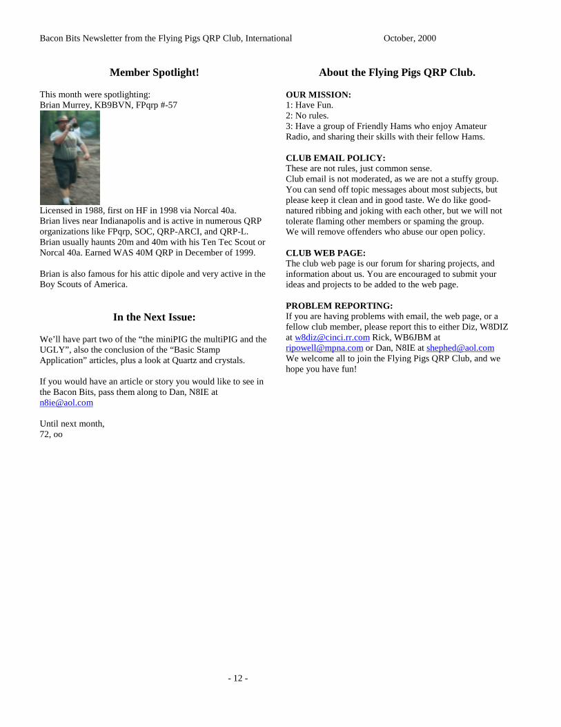
This month were spotlighting:Brian Murrey, KB9BVN, FPqrp #-57
Licensed in 1988, first on HF in 1998 via Norcal 40a.Brian lives near Indianapolis and is active in numerous QRPorganizations like FPqrp, SOC, QRP-ARCI, and QRP-L.Brian usually haunts 20m and 40m with his Ten Tec Scout orNorcal 40a. Earned WAS 40M QRP in December of 1999.
Brian is also famous for his attic dipole and very active in theBoy Scouts of America.
In the Next Issue:
We’ll have part two of the “the miniPIG the multiPIG and theUGLY”, also the conclusion of the “Basic StampApplication” articles, plus a look at Quartz and crystals.
If you would have an article or story you would like to see inthe Bacon Bits, pass them along to Dan, N8IE [email protected]
Until next month,72, oo
About the Flying Pigs QRP Club.
OUR MISSION:1: Have Fun.2: No rules.3: Have a group of Friendly Hams who enjoy AmateurRadio, and sharing their skills with their fellow Hams.
CLUB EMAIL POLICY:These are not rules, just common sense.Club email is not moderated, as we are not a stuffy group.You can send off topic messages about most subjects, butplease keep it clean and in good taste. We do like good-natured ribbing and joking with each other, but we will nottolerate flaming other members or spaming the group.We will remove offenders who abuse our open policy.
CLUB WEB PAGE:The club web page is our forum for sharing projects, andinformation about us. You are encouraged to submit yourideas and projects to be added to the web page.
PROBLEM REPORTING:If you are having problems with email, the web page, or afellow club member, please report this to either Diz, W8DIZat [email protected] Rick, WB6JBM [email protected] or Dan, N8IE at [email protected] welcome all to join the Flying Pigs QRP Club, and wehope you have fun!