The Physics of Accelerators - CERN Accelerator School
38
The Physics of Accelerators C.R. Prior Rutherford Appleton Laboratory and Trinity College, Oxford
Transcript of The Physics of Accelerators - CERN Accelerator School

The Physics of AcceleratorsC.R. PriorRutherford Appleton Laboratoryand Trinity College, Oxford
ContentsBasic concepts in the study of Particle Accelerators Methods of acceleration
Linacs and rings
Controlling the beamConfinement, acceleration, focusing
Electrons and protonsSynchrotron radiationLuminosity
Pre-requisites
Basic knowledge for the study of particle beams:Applications of relativistic particle dynamicsClassical theory of electromagnetism (Maxwell’s equations)
More advanced studies requireHamiltonian mechanicsOptical conceptsQuantum scattering theory, radiation by charged particlesComputing ability

Applications of AcceleratorsBased on
directing beams to hit specific targets or colliding beams onto each otherproduction of thin beams of synchrotron light
Particle physicsstructure of the atom, standard model, quarks, neutrinos, CP violation
Bombardment of targets used to obtain new materials with different chemical, physical and mechanical properties
Synchrotron radiation covers spectroscopy, X-ray diffraction, x-ray microscopy, crystallography of proteins. Techniques used to manufacture products for aeronautics, medicine, pharmacology, steel production, chemical, car, oil and space industries.
In medicine, beams are used for Positron Emission Tomography (PET), therapy of tumours, and for surgery.
Nuclear waste transmutation – convert long lived nucleides into short-lived waste
Generation of energy (Rubbia’s energy amplifier, heavy ion driver for fusion)


Basic Concepts ISpeed of lightRelativistic energyRelativistic momentum
E-p relationship
Kinetic energyEquation of motion under Lorentz force
18 secm1099792458.2 −×=c2
02 cmmcE γ==
cmmvp βγ0==
2
21
2
2
111β
γβ−
=⎟⎟⎠
⎞⎜⎜⎝
⎛−==
−
cv
cv
220
22
2
cmpcE
+=
pcE,β ≈≈− 1particlesicrelativistultra
( )120
20 −=−= γcmcmET
( ) ( )BvEqvdtdmf
dtpd rrrrrr
∧+=⇒= γ0

Basic Concepts II
Electron charge
Electron volts
Energy in eV
Energy and rest massElectronProtonNeutron
Coulombs106021.1 19−×=e
joule 1060211 eV1 19-. ×=
[ ]e
cme
mcE2
02
eV γ==
kg1078.1eV1 362 −×=c
kg109.109keV0.511 -3120 ×== cm
kg101.673MeV3.938 -2720 ×== cm
kg101.675MeV6.939 -2720 ×== cm

Motion in Electric and Magnetic FieldsGoverned by Lorentz force
Acceleration along a uniform electric field (B=0)
[ ]BvEqdtpd rrrr
×+=
( ) EpE
qcBvEpE
qcdtdE
dtpdpc
dtdEE
cmcpE
rrrrrr
rr
r
⋅=∧+⋅=⇒
⋅=⇒
+=
22
2
420
222
cvtmeEx
vtz<<
⎪⎭
⎪⎬⎫
≈
≈forpath parabolic
22
0γ
A magnetic field does not alter a particle’s energy. Only an electric field can do this.
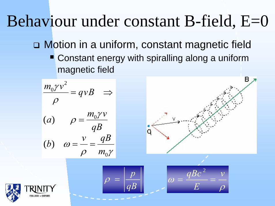
Behaviour under constant B-field, E=0Motion in a uniform, constant magnetic field
Constant energy with spiralling along a uniform magnetic field
γρω
γρ
ργ
0
0
20
)(
)(
mqBvb
qBvma
Bvqvm
==
=
⇒=
qBp
=ρρ
ω vE
qBc==
2

Method of Acceleration: Linear Simplest example is a vacuum chamber with one or more DC accelerating structures with the E-field aligned in the direction of motion.
Limited to a few MeVTo achieve energies higher than the highest voltage in the system, the E-fields are alternating at RF cavities.
Avoids expensive magnets
No loss of energy from synchrotron radiation (q.v.)
But requires many structures, limited energy gain/metre
Large energy increase requires a long accelerator
SLAC linear accelerator
SNS Linac, Oak Ridge
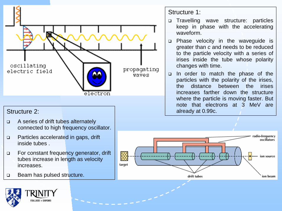
Structure 1:Travelling wave structure: particles keep in phase with the accelerating waveform. Phase velocity in the waveguide is greater than c and needs to be reduced to the particle velocity with a series of irises inside the tube whose polarity changes with time. In order to match the phase of the particles with the polarity of the irises, the distance between the irises increases farther down the structure where the particle is moving faster. But note that electrons at 3 MeV are already at 0.99c.Structure 2:
A series of drift tubes alternately connected to high frequency oscillator.
Particles accelerated in gaps, drift inside tubes .
For constant frequency generator, drift tubes increase in length as velocity increases.
Beam has pulsed structure.

Methods of Acceleration: CircularGeorge Lawrence and cyclotron
Use magnetic fields to force particles to pass through accelerating fields at regular intervals
CyclotronsConstant B fieldConstant accelerating frequency fSpiral trajectoriesFor synchronism f = nω, which is possible only at low energies, γ~1.Use for heavy particles (protons, deuterons, α-particles).
ρω v
EqBc
==2
qBp
=ρ

Methods of Acceleration: Circular
Higher energies => relativistic effects => ω no longer constant.
Particles get out of phase with accelerating fields; eventually no overall acceleration.
Isochronous cyclotronVary B to compensate and keep f constant.For stable orbits need both radial (because ρ varies) and azimuthal B-field variationLeads to construction difficulties.
Synchro-cyclotronModulate frequency f of accelerating structure instead.In this case, oscillations are stable (McMillan & Veksler, 1945)
ωnf =
ρω v
EqBc
==2
qBp
=ρ

BetatronParticles accelerated by the rotational electric field generated by a time varying magnetic field.
In order that particles circulate at constant radius:
dtdEr
SdBdtdldE
tBE
Φ−=⇒
⋅−=⋅⇔
∂∂
−=∧∇
∫∫∫
π2
rrrr
rr
( )
( ) ∫∫=⇒
Φ=−=−=⇒
−=
dSBr
trB
dtd
rrE
qrptrB
qrpB
2
2
121,
21,
π
π&&
B-field on orbit is one half of the average B over the circle. This imposes a limit on the energy that can be achieved. Nevertheless the constant radius principle is attractive for high energy circular accelerators.
Oscillations about the design orbit are called betatron oscillations
Magnetic flux, Φ
Generated E-field
r

Methods of Acceleration: CircularSynchrotron
Principle of frequency modulation but in addition variation in time of B-field to match increase in energy and keep revolution radius constant.
Magnetic field produced by several bending magnets
(dipoles), increases linearly with momentum. For q=e
and high energies:
.
Practical limitations for magnetic fields => high energies
only at large radius
e.g. LHC E = 8 TeV, B = 10 T, ρ = 2.7 km
ωnf =
ρω v
EqBc
==2
qBp
=ρ
chargeunit per [m] [T] 0.3[GeV]so ρBEceE
epBρ ≈≈=

Types of SynchrotronStorage rings: accumulate particles and keep circulating for long periods; used for high intensity beams to inject into more powerful machines or synchrotron radiation factories.
Colliders: two beams circulating in opposite directions, made to intersect; maximises energy in centre of mass frame.
B
ωE
Variation of parameters with time in the ISIS
synchrotron:
B=B0-B1 cos(2πft)
Fixed Field Alternating Gradient Circular Machines (FFAG)
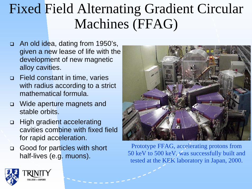
An old idea, dating from 1950’s, given a new lease of life with the development of new magnetic alloy cavities.Field constant in time, varies with radius according to a strict mathematical formula.Wide aperture magnets and stable orbits.High gradient accelerating cavities combine with fixed field for rapid acceleration.Good for particles with short half-lives (e.g. muons).
Prototype FFAG, accelerating protons from 50 keV to 500 keV, was successfully built and tested at the KEK laboratory in Japan, 2000.

Summary of Circular MachinesMachine RF frequency
fMagnetic Field B
Orbit Radius ρ
Comment
Cyclotron constant constant increases with energy
Particles out of synch with RF; low energy beam or heavy ions
Isochronous Cyclotron
constant varies increases with energy
Particles in synch, but difficult to create stable orbits
Synchro-cyclotron varies constant increases with energy
Stable oscillations
Synchrotron varies varies constant Flexible machine, high energies possible
FFAG varies constant in time, varies with radius
increases with energy
Increasingly attraction option for 21st century designs
ρω v
EqBc
==2
qBp
=ρ

Confinement, Acceleration and Focusing of Particles
qBp
=ρBy increasing E (hence p) and Btogether, possible to maintain a constant radius and accelerate a beam of particles.
In a synchrotron, the confining magnetic field comes from a system of several magnetic dipoles forming a closed arc. Dipoles are mounted apart, separated by straight sections/vacuum chambers including equipment for focusing, acceleration, injection, extraction, collimation, experimental areas, vacuum pumps.
ISIS dipole

Ring Layout
Injection
Extraction
Collimation
R.F.
Dipoles
Focusing elements
DipolesMean radius of ring R > ρ
e.g. CERN SPS
R = 1100 m, ρ = 225 m
Can also have large machines with a large number of dipoles each of small bending angle.
e.g. CERN SPS
744 dipole magnets, 6.26 mlong, angle θ = 0.48o

Ring ConceptsImportant concepts in rings:
Revolution period τ
Revolution frequency ω
If several bunches in a machine, introduce RF cavities
in straight sections with fields oscillating at a multiple of
the revolution frequency. h is the harmonic number.
Energy increase ∆E when particles pass RF cavities ⇒can increase energy only so far as can increase B-field in dipoles to keep constant ρ.
cL
vR≈=
πτ 2
Lc
≈=τπ
ω 12
Lhchrf ≈= ωω
qBp
=ρ
qpB =ρ
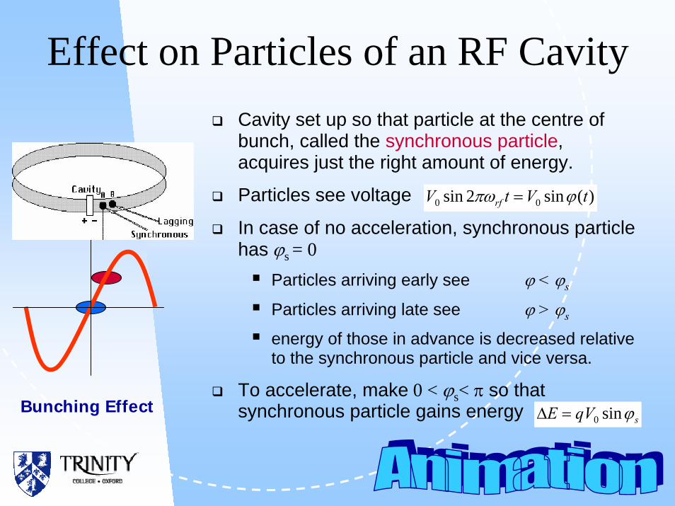
Effect on Particles of an RF CavityCavity set up so that particle at the centre of bunch, called the synchronous particle, acquires just the right amount of energy.
Particles see voltage
In case of no acceleration, synchronous particle has ϕs = 0
Particles arriving early see ϕ < ϕs
Particles arriving late see ϕ > ϕs
energy of those in advance is decreased relative to the synchronous particle and vice versa.
To accelerate, make 0 < ϕs< π so that synchronous particle gains energy
)(sin2sin 00 tVtV rf ϕπω =
Bunching EffectsqVE ϕsin0=∆
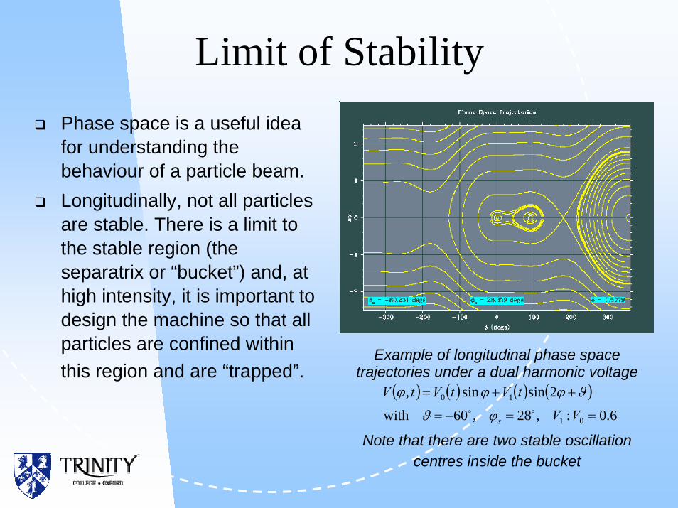
Limit of StabilityPhase space is a useful idea for understanding the behaviour of a particle beam.Longitudinally, not all particles are stable. There is a limit to the stable region (the separatrix or “bucket”) and, at high intensity, it is important to design the machine so that all particles are confined within this region and are “trapped”.
Example of longitudinal phase space trajectories under a dual harmonic voltage
Note that there are two stable oscillation centres inside the bucket
( ) ( ) ( ) ( )6.0:,28,60with
2sinsin,
01
10
==−=
++=
VV
tVtVtV
soo ϕϑ
ϑϕϕϕ
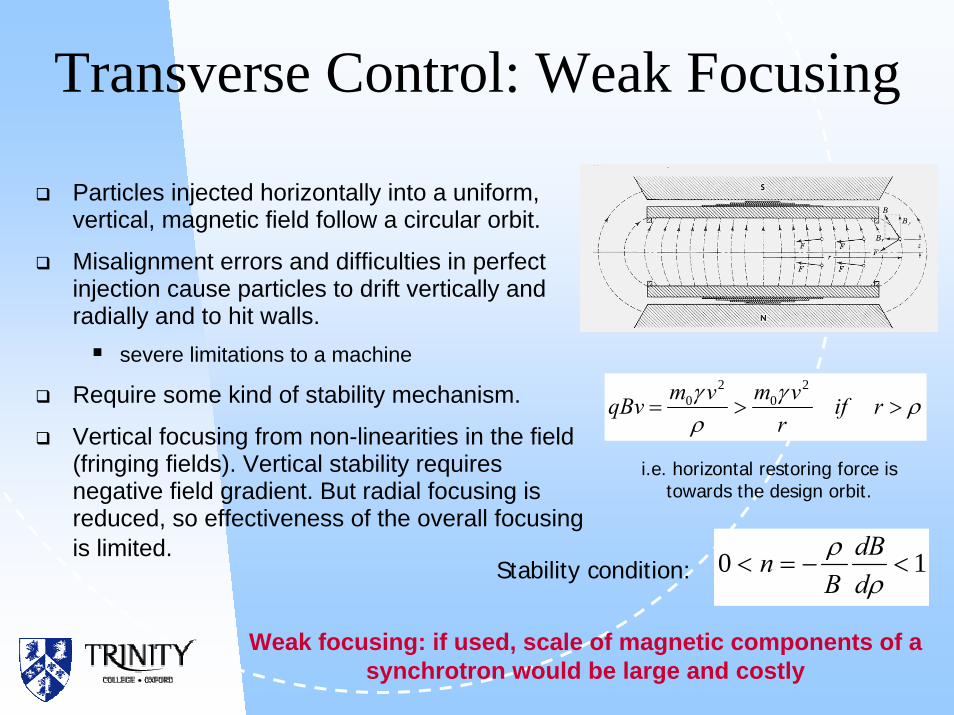
Transverse Control: Weak Focusing
Particles injected horizontally into a uniform, vertical, magnetic field follow a circular orbit.
Misalignment errors and difficulties in perfect injection cause particles to drift vertically and radially and to hit walls.
severe limitations to a machine
Require some kind of stability mechanism.
Vertical focusing from non-linearities in the field (fringing fields). Vertical stability requires negative field gradient. But radial focusing is reduced, so effectiveness of the overall focusing is limited.
ργργ
>>= rifr
vmvmqBv2
02
0
i.e. horizontal restoring force is towards the design orbit.
10 <−=<ρ
ρddB
BnStability condition:
Weak focusing: if used, scale of magnetic components of a synchrotron would be large and costly
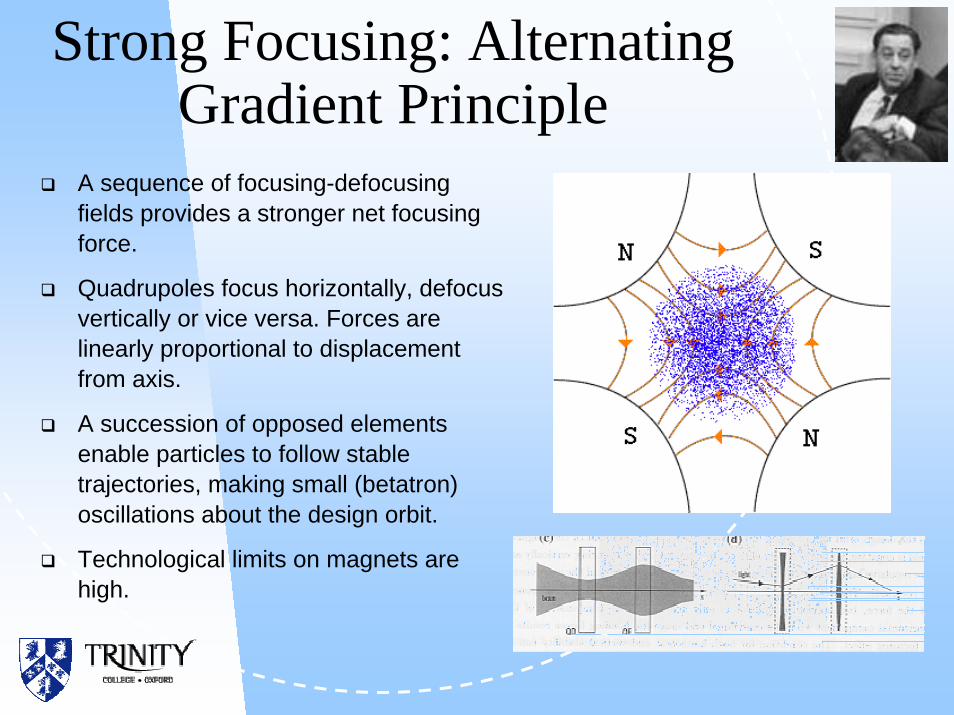
Strong Focusing: Alternating Gradient Principle
A sequence of focusing-defocusing fields provides a stronger net focusing force.
Quadrupoles focus horizontally, defocus vertically or vice versa. Forces are linearly proportional to displacement from axis.
A succession of opposed elements enable particles to follow stable trajectories, making small (betatron) oscillations about the design orbit.
Technological limits on magnets are high.
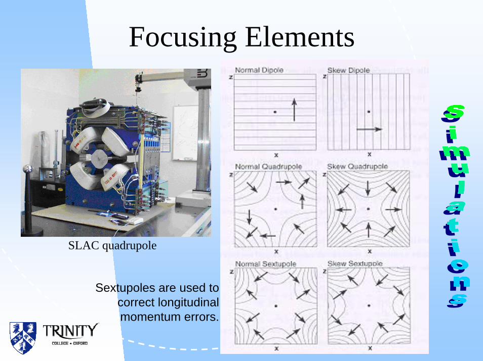
Focusing Elements
Sextupoles are used to correct longitudinal momentum errors.
SLAC quadrupole

Hill’s EquationEquation of transverse motion
Drift:
Solenoid:
Quadrupole:
Dipole:
Sextupole:
Hill’s Equation:
0,0 =−′′=+′′ ykyxkx
( ) 02,022 =−′′=−+′′ kxyyyxkx
0,0 =′′=′′ yx
0,012 =′′=+′′ yxx
ρ
0)(,0)( =+′′=+′′ yskyxskx yx
George Hill
02,02 =′−′−′′=′+′+′′ xkxkyykykx

Transverse Phase SpaceUnder linear forces, any particle moves on an ellipse in phase space (x,x´).Ellipse rotates in magnets and shears between magnets, but its area is preserved: Emittance
General equation of ellipse is
α, β, γ are functions of distance (Twiss parameters), and ε is a constant. Area = πε.
For non-linear beams can use 95% emittance ellipse or RMS emittance
(statistical definition)
x
x´
x
x´
εγαβ =+′+′ 22 2 xxxx
222 xxxxrms ′−′=ε

Thin Lens Analogy of AG Focusing
inout1101
⎟⎟⎠
⎞⎜⎜⎝
⎛′⎟
⎟
⎠
⎞
⎜⎜
⎝
⎛−=⎟⎟
⎠
⎞⎜⎜⎝
⎛′ x
x
fxxx
f
fxx =′∆ Effect of a thin
lens can be represented by a matrix
In a drift space of length l, x′ is unaltered but x → x+lx′ inout 10
1⎟⎟⎠
⎞⎜⎜⎝
⎛′⎟⎟
⎠
⎞⎜⎜⎝
⎛=⎟⎟
⎠
⎞⎜⎜⎝
⎛′ x
xlxx
In an F-drift-D system, combined effect is ⎟
⎟⎟
⎠
⎞
⎜⎜⎜
⎝
⎛
+−
−=
⎟⎟⎠
⎞⎜⎜⎝
⎛−⎟⎟
⎠
⎞⎜⎜⎝
⎛⎟⎟⎠
⎞⎜⎜⎝
⎛
fl
fl
lfl
f
l
f 1
1
1101
101
1101
2
Thin lens of focal length f 2/ l, focusing overall, if l< f. Same for D-drift-F ( f → - f ), so system of AG lenses can focus in both planes simultaneouslyout
2in
1
0⎟⎟⎟⎟
⎠
⎞
⎜⎜⎜⎜
⎝
⎛
⎟⎠⎞
⎜⎝⎛ −
⎟⎠⎞⎜
⎝⎛ −
⇒⎟⎟⎠
⎞⎜⎜⎝
⎛
xfl
xfl
x
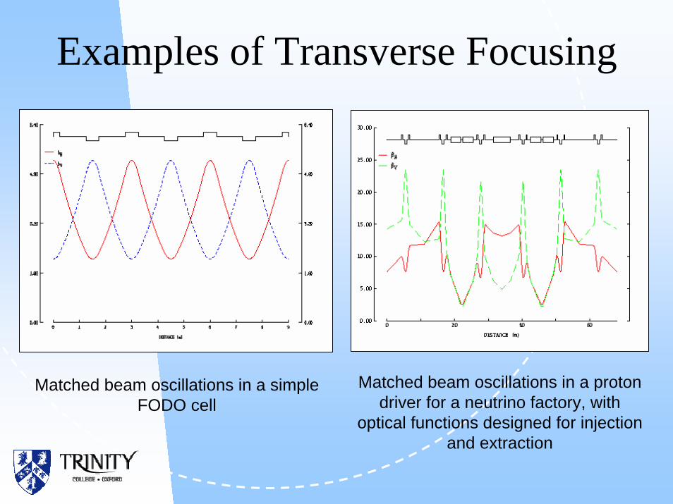
Examples of Transverse Focusing
Matched beam oscillations in a simple FODO cell
Matched beam oscillations in a proton driver for a neutrino factory, with
optical functions designed for injection and extraction

Ring Studies
Typical example of ring design
Basic latticeBeam envelopesPhase advances, resonancesMatchingAnalysis of phase space non-linearitiesPoincaré maps

Electrons and Synchrotron RadiationParticles radiate when they are accelerated, so charged particles moving in the magnetic dipoles of a lattice in a ring (with centrifugal acceleration) emit radiation in a direction tangential to their trajectory.
After one turn of a circular accelerator, total energy lost by synchrotron radiation is
Proton mass : electron mass = 1836. For the same energy and radius,
[ ] [ ][ ][ ]
4
20
18
/GeVm10034.6GeV ⎟⎟
⎠
⎞⎜⎜⎝
⎛×=∆
−
cmGeVEE
ρ
1310: ≈∆∆ pe EE

Synchrotron RadiationIn electron machines, strong dependence of radiated energy on energy.
Losses must be compensated by cavities
Technological limit on maximum energy a cavity can deliver ⇒ upper band for electron energy in an accelerator:
Better to have larger accelerator for same power from RF cavities at high energies.
To reach twice a given energy with same cavities would require amachine 16 times as large.
e.g. LEP with 50 GeV electrons, ρ =3.1 km, circumference =27 km:Energy loss per turn is 0.18 GeV per particle
Energy is halved after 650 revolutions, in a time of 59 ms.
[ ] [ ]( ) 4/1maxmax m10GeV EE ∆= ρ
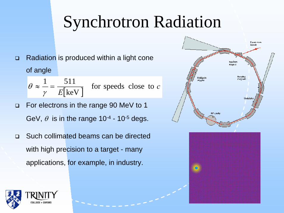
Synchrotron Radiation
Radiation is produced within a light cone
of angle
For electrons in the range 90 MeV to 1
GeV, θ is in the range 10-4 - 10-5 degs.
Such collimated beams can be directed
with high precision to a target - many
applications, for example, in industry.
[ ] cE
toclosespeedsforkeV
5111=≈
γθ

Argonne Light Source: aerial view

Diamond Light Source: construction site August 2004

LuminosityMeasures interaction rate per unit cross section - an important concept for colliders.Simple model: Two cylindrical bunches of area A. Any particle in one bunch sees a fraction Nσ /A of the other bunch. (σ=interaction cross section). Number of interactions between the two bunches is N2σ /A. Interaction rate is R = f N2σ /A, and
Luminosity
CERN and Fermilab p-pbar colliders have L ~ 1030 cm-2s-1. SSC was aiming for L ~ 1033 cm-2s-1
Area, A
ANfL
2
=

Reading
E.J.N. Wilson: Introduction to AcceleratorsS.Y. Lee: Accelerator PhysicsM. Reiser: Theory and Design of Charged Particle BeamsD. Edwards & M. Syphers: An Introduction to the Physics of High Energy AcceleratorsM. Conte & W. MacKay: An Introduction to the Physics of Particle AcceleratorsR. Dilao & R. Alves-Pires: Nonlinear Dynamics in Particle AcceleratorsM. Livingston & J. Blewett: Particle Accelerators