The Physical Layer Chapter 2. The Theoretical Basis for Data Communication Fourier Analysis...
71
The Physical Layer Chapter 2
-
Upload
leona-robinson -
Category
Documents
-
view
233 -
download
0
Transcript of The Physical Layer Chapter 2. The Theoretical Basis for Data Communication Fourier Analysis...

The Physical Layer
Chapter 2

The Theoretical Basis for Data Communication
• Fourier Analysis
• Bandwidth-Limited Signals
• Maximum Data Rate of a Channel

Fourier Analysis
G(t) periodic function:
G(t) = ½ c + an sin(2nft) + bn cos(2nft)
an = 2/T G(t)sin(2nft) dt
bn = 2/T G(t)cos(2nft) dt
c = 2/T G(t) dt

Bandwidth-Limited Signals
A binary signal and its root-mean-square Fourier amplitudes.
(b) – (c) Successive approximations to the original signal.
bandwidth

Bandwidth-Limited Signals (2)
(d) – (e) Successive approximations to the original signal.

Bandwidth-Limited Signals (3)
• Period = 1/Frequency• Harmonics: Term of the sine/cosine function• Bandwidth: Range of transmitted frequencies without a strong attenuation. It is a physical property of the transmission medium (depends on
construction, thickness, length, …)• Transmission media are not perfect: Noise: thermal (motion of electrons) or induced (by equipments)
noise, or crosstalk (effect of one wire on another) Attenuation: loss of energy (amplifiers help) Distortion: change in shape in composite signals (different
harmonics arrive with different delays)
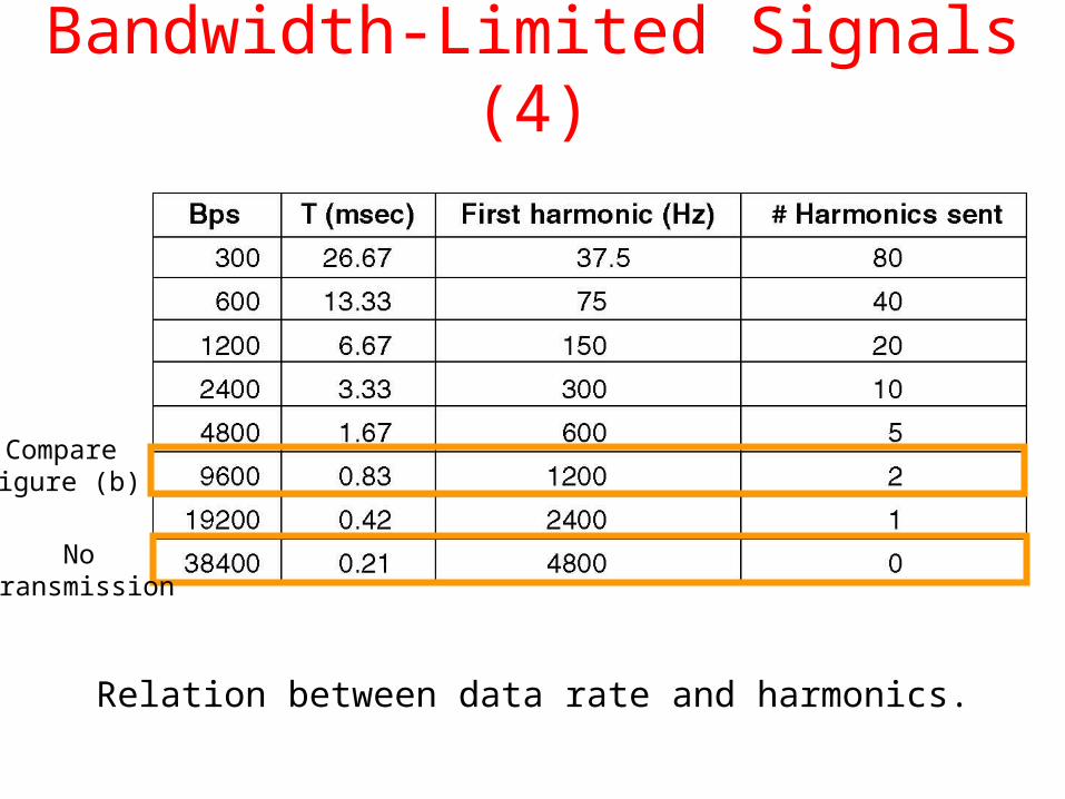
Bandwidth-Limited Signals (4)
Relation between data rate and harmonics.
Compare figure (b)
Notransmission

Maximum Data Rate of a Channel
• Without noise (Nyquist, 1924): max. rate = 2B log(L) bits/sec where: B: bandwidth of the channel (after a low pass filter) L: Number of discrete levels (e.g. binary: L = 2) Example: A noiseless binary 3 kHz channel cannot exceed the rate 6000 bps.
• With noise (Shannon 1944):max. rate (or capacity) C = B log(1 + S/N) bits/sec
where: B: bandwidth of the channel S/N: Signal to noise ratio Example: Extremely noisy channel (N very high). C = B log (1 + 0) = 0 (as expected: no data can be sent through this channel)

Maximum Data Rate of a Channel
• Decibel (dB): For measuring signal strength engineers use the concept of decibel: dB is negative: signal is attenuated dB is positive: signal is amplified
dB = 10 log10(P1/P2)
Example: P1/P2 = ½ 10log10(0.5) = -3dB attenuation Reason for using dB: decibel can be added/subtracted easily:
Amp
-3 dB -3 dB7 dB
1 dB

Guided Transmission Data
• Magnetic Media
• Twisted Pair
• Coaxial Cable
• Fiber Optics
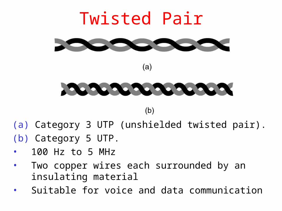
Twisted Pair
(a) Category 3 UTP (unshielded twisted pair).
(b) Category 5 UTP.
• 100 Hz to 5 MHz
• Two copper wires each surrounded by an insulating material
• Suitable for voice and data communication

Twisted Pair• Cables are twisted to minimize noise effects.
• In the past two parallel cables have been used:

Noise on Twisted Pair Lines

Shielded Twisted Pair Cable (STP)
More expensive than UTP Less susceptible to noise Only in IBM installation

Coaxial Cable
A coaxial cable.

Fiber Optics
Refraction of light

Fiber Optics
Critical Angle
Reflection
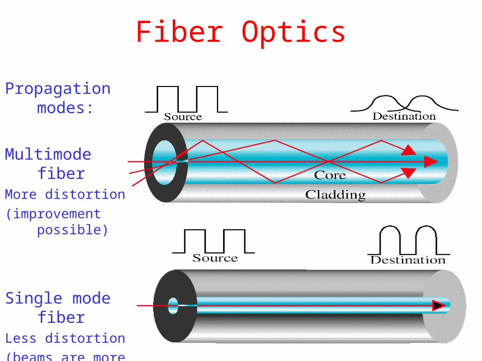
Fiber Optics
Propagation modes:
Multimode fiberMore distortion
(improvement possible)
Single mode fiberLess distortion
(beams are more focused)

Fiber Optics• Light sources: light-emitting-diode (LED), Injection laser diode (ILD)
• Light detector: Photodiode: translates light to an electrical pulse. Response time: 1 nsec max. data rate: 1Gbps. Limiting factor is still computing and not communication power!
Why? Fiber technology can achieve up to 50000 Gbps !!!

Fiber Optics+ Noise resistant: fiber optics uses light and not current, therefore, it
is resistant to external noise. + Less attenuation: The signal can travel for miles without regeneration. + Higher bandwidth: currently limiting factor is signal generation and reception technology.
- Higher cost: Fiber-optic cable is expensive, because of its precise manufacturing. Also, laser sources are expensive. - More installation/maintenance efforts: Any cracking of the core alters the signal. Connections must be perfectly aligned and matched for core size and provide a completely light-tight seal. - More fragile: Glass fiber is more easily broken than wire .

Fiber Optic Networks
A fiber optic ring with active repeaters.

Fiber Optic Networks (2)
A passive star connection in a fiber optics network.

Wireless Transmission
• Radio Transmission
• Microwave Transmission
• Satellite Communication

Radio Communication Band
The electromagnetic spectrum and its uses for communication.

Propagation Types

Propagation Types
• Surface propagation: Waves travel through the lowest level of the atmosphere emanating in all directions. Distance depends on the amount of power in the signal.
• Tropospheric propagation: Two modes: either from antenna to antenna (line-of-sight) or broadcast into the upper layers of troposphere (where reflection to earth takes place). Latter method allows greater distances.
• Ionospheric propagation: Similar to last type. Waves hit the ionosphere and are reflected back . It allows for even greater distance with less power.
• Line-of-Sight propagation: Very high signals are transmitted in straight lines directly from antenna to antenna (which should be tall enough and facing each other). More sensitive for reflection, since signals cannot be completely focused.
• Space propagation: Satellites are used instead of atmospheric reflection. Basically like line-of-sight transmission with an intermediary (the satellite). Allows very long distances.

VLF
LF
Frequency Ranges an Their Uses
MF
HF
Surface propagationSensitive to noise
Surface propagationSensitive to attenuation
Ionospheric propagation
Tropospheric propagationAbsorption by ionosphere possible(use of line-of-sight helps)

VHF
UHF
Frequency Ranges an Their Uses
Line-of-sight propagation
Line-of-sight propagation

Frequency Ranges an Their Uses
SHF
EHF
Line-of-sight orspace propagation(satellite microwavesor radar communication)
Space propagation(mainly for scientific use)

Terrestrial Microwaves• Propagated using line-of-sight transmission.
• Provide the basis for most existent telephone systems
• Propagate in one direction only
2 frequencies are needed e.g. for a phone conversation
• Repeaters are used to achieve longer distances:• Repeaters are installed on each antenna
• Signal received on each antenna is converted and transmitted to the next antenna

Satellite Communication • Similar to line-of-sight transmission.
• Satellite acts as a supertall antenna.
• No limitation by the curvature of the earth.
longer distances achievable
• Expensive, but leasing time and frequencies on existent ones cheap

Geosynchronous Satellites• Fixed satellites are useless: They face earth antennas only for short time
like a stopped clock is accurate twice a day! • To ensure constant communication the satellite must move at the same
speed as the earth.• One geosynchronous satellite cannot cover the whole earth: at least three equidistant satellites are needed

Frequency Bands for Satellite Communication
The principal satellite bands.

Communication Satellites
VSATs (Very Small Aperture Terminals) using a hub.
• VSAT do not have enough power to communicate directly with each other.• A hub is used relay traffic between VSTAs

Modulation• Modems: Convert a digital signal to an analog one and vice versa.• Forms of modulation:
• Amplitude modulation• Frequency modulation• Phase modulation
• Amplitude Modulation
Amplitude > 0 means 1, amplitude = 0 means 0

Modulation• Frequency Modulation
More frequent means 1, less frequent means 0

Modulation• Phase Modulation
Phase changes

Bit Rate Versus Baud Rate
• Bit rate: Number of bits transmitted during one second
• Baud rate: Number of signal units required to represent those bits.
• Bit rate equals the baud rate times the number of bits represented by each signal unit:
Bit rate = Baud rate x Number of bits per signal unit
• This means that the bit rate is always greater or equal the baud rate:
Bit rate >= Baud rate
• Analogy in transportation:
• Bit: passenger
• Baud: car
• If 100 cars go from A to B carrying one person, then 100 person are transported ( Bit rate = baud rate)
• If, however, each car carries 4 persons, then 400 persons are transported ( Bit rate = 4 x baud rate)
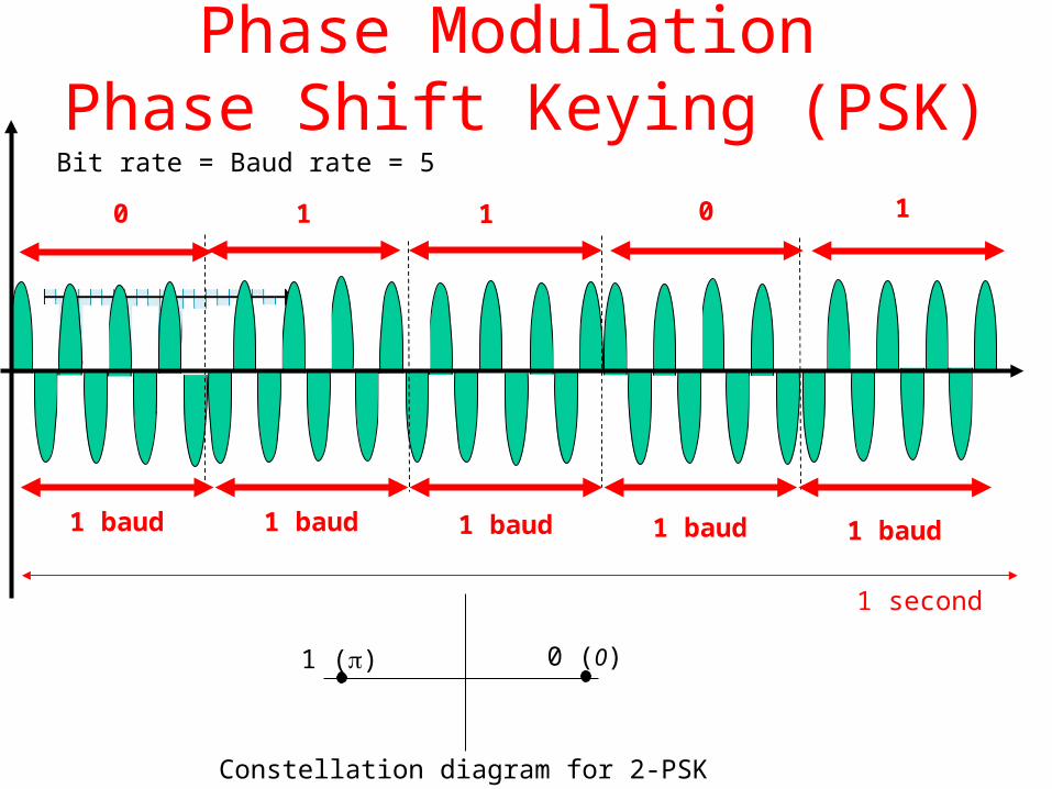
Phase Modulation Phase Shift Keying (PSK)
0 1 1 0 1
1 () 0 (0)
Constellation diagram for 2-PSK
1 second
1 baud 1 baud 1 baud 1 baud 1 baud
Bit rate = Baud rate = 5

4-PSK
01 10 10 11 00
1 second
1 baud 1 baud 1 baud 1 baud 1 baud
10 () 00 (0)
Constellation diagram for 4-PSK
01 ()
11 (3)
Bit rate = 10 Baud rate = 5

8-PSK and higher
010 ()
001 ()
000 ()
011 ()
100 ()
101 (5)
110 (3)
010 (7)
Constellation diagram for 8-PSK
16-PSK, 32-PSK, … are also possible

Quadrature Amplitude Modulation (QAM)
• Idea: Combine changes of amplitude with changes of phase.• Example 4-QAM: 1 amplitude and 4 phases
0001
10 11
• Example 8-QAM: 2 amplitudes and 4 phases
000
001
011
010
101
111
110
100

8-QAM
101
1 second
1 baud
Bit rate = 24 Baud rate = 8
1 baud 1 baud 1 baud 1 baud 1 baud 1 baud 1 baud
100 001 000 010 011 110 111
• Whenever the amplitude or the phase changes, a new symbol is transmitted.• In general, number of amplitudes less than that of phases because amplitudes are more sensitive to
noise.
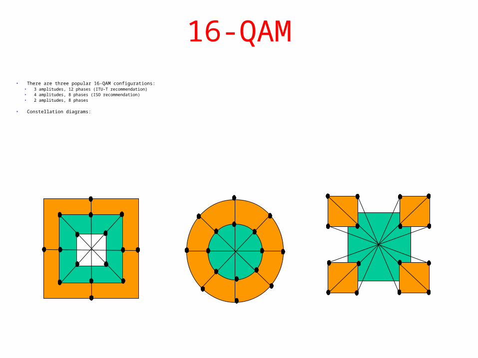
16-QAM
• There are three popular 16-QAM configurations:• 3 amplitudes, 12 phases (ITU-T recommendation)• 4 amplitudes, 8 phases (ISO recommendation)• 2 amplitudes, 8 phases
• Constellation diagrams:

Multiplexing vs. No Multiplexing

Frequency Division Multiplexing (FDM)
• For analog devices (e.g. phones)• Channels carry the signals with different frequencies but at the same time.

FDM
• Similar signals as input• Signals are modulated (e.g. AM, FM) using different carrier signals (f1, f2, f3)• Combined signal is send through the link

FDM
• Filters are used to decompose the multiplexed signal into its constituents• Individual signal are then passed to a demodulator to generate the original signal

Wave Division Multiplexing
• For fiber optic channels only.• Same idea as FDM, but more reliable than FDM.
prisms

Time Division Multiplexing (TDM)
• For digital devices (computers).• Like FDM, bandwidth of transmission medium high enough to accommodate
the different signals.• Conceptual view:
Channel sectioned by time rather by frequency
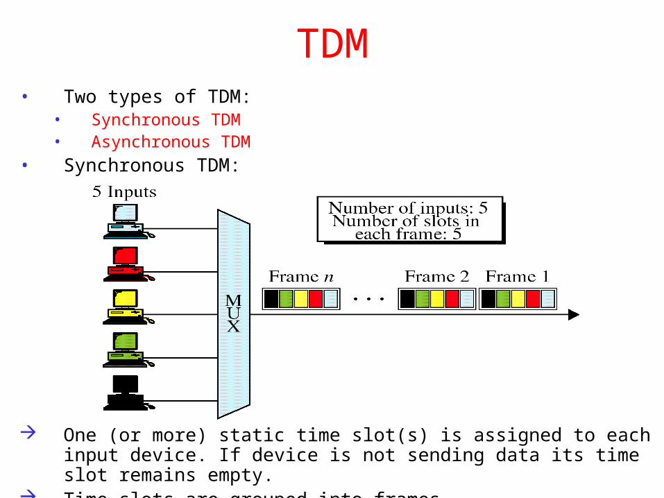
TDM• Two types of TDM:
• Synchronous TDM• Asynchronous TDM
• Synchronous TDM:
One (or more) static time slot(s) is assigned to each input device. If device is not sending data its time slot remains empty.
Time slots are grouped into frames.

Synchronous TDM
empty slot
• Different data rates for input devices possible: then more slots for faster devices needed.
in this case the faster rate should be integer multiples of the other ones.• If a data rate is not an integer multiples of another, e.g. 2.75 times another rate, then bit
stuffing is used (bits are added by the multiplexer and discarded by the demultiplexer)• Main problem: wasted bandwidth because of potential empty slots.

Asynchronous TDM
• Also frame-based.• Unlike synchronous TDM:
• Number of slots in a frame less than number of input lines.• Slots are not statically assigned to input lines, any sending device can use an
available slot.

Asynchronous TDM
Actual data and addresses, which are needed by the demultiplexer.In synchronous TDM, there is no need for addresses (informationlies implicitly in the position of a slot) .
Problem: Addresses means overhead!

Inverse Multiplexing
Inverse multiplexing is neededfor bandwidth on demand:Lines of lower bandwidth areused, if needed.For example: - All lines are used for telephone calls. - If video transmission is needed, the video data are broken up and sent over two or more lines.

Hierarchy of Multiplexers
FDM
4 KHz 48 KHz(12 voice channels)
240 KHz(60 voice channels)
2.52 MHz(600 voice channels)
12 v
oice
cha
nnel
s
10

Three forms of switching:
a) Circuit Switching
b) Packet Switching
c) Message Switching
Switching

Switched Networks
• Main idea: Reduce number and length of links.• Example: In the network above, if 7 computers are to be connected to 5 ones, we could use dedicated links for
each pair; this would lead to 7x5 =35 links, which will be probably not fully utilized.

Circuit-Switched Networks
• Physical path from sender to receiver is established at connection time and is held for the communicating pair during the whole communication. Used mostly in telephone networks.
+ Dedicated links for the whole session no congestion and delays- Connection setup delays the start of communication- Less utilization of links, if traffic is not high.

Switches• A switch is a device (newer are computers) with n input links and m output links
that creates a temporary connection between an input link and an output link.
• Example: n-by-n folded switch: connects n devices to each other:

Circuit-Switched Network
• Circuit switching uses two techniques:• Space division switches• Time division switches
• Space division switches: Paths are separated spatially.• Example: Crossbar switch
transistor
Too many switches needed: With n inputs and m outputs nxm switches are needed.

Multistage Switch
• Multistage switches use different crossbar switches in such a way that the number of crosspoints is minimized.
15 inputs and 15 outputs For a single crossbar switch 15x15 = 225 crosspoints are necessary. Now only 3x10 + 2x9 + 3x10 = 78 crosspoints are needed.

Multistage Switch
Multistage switches allow for different paths between source and destination:
Blocking Problem: In multistage switches the traffic can be blocked:
e.g. suppose 6 is calling 10 (over B) and 11 is calling 6 (over A), the intermediate switches (A and B) are occupied and connection cannot be made for 4 and 9.
6
11
A
B

Time Division Switches
• No spatial separation; use of time division multiplexing (TDM) instead:
• Combining TDM with time-slot interchange (TSI) leads to switching:

Time Division Switches
• Time-slot interchange:
• TDM Bus: An alternative to TSI; a bus is used instead of a RAM

Combination of Space and Time Division Switches
• Space division multiplexing is instantaneous but needs a lot of switches and may cause blocking. On the other hand time division switching does not need switches but causes more delay (processing time of TSI). Combining them leads to a better design with less delay and blocking probability.
• Combinations: time-space-time (TST), time-space-space-time (TSST), space-time-time-space (STTS), or other:
Packet Switching
• Packet switching:• Data is transmitted in discrete units (packets) of possibly variable length.• Packets include the actual data and header information (e.g. destination
address)• Packets are transmitted over network node to node; in each node they are
briefly stored (store-and-forward).
• Two types of packet switching:• Datagram approach• Virtual circuit approach
• Datagram approach:• Each datagram (packet) is treated independently from other datagrams.• Datagrams of same message may have different paths from source to
destination.• Datagrams of same message may arrive out of order.

Datagrams
• Example: A message with 4 datagrams. different paths for different datagrams at destination, datagrams are out of order.

Virtual Circuits• A single route is chosen at the beginning of the session and all packets follow that route.• Two types:
• SVC: Switched Virtual Circuit• PVC: Permanent Virtual Circuit
• SVC:
• PVC:
12
12
12 12
Connection establishment Data transfer Connection release
12
12
12 12
Permanent connection for the duration of the lease

Circuit Switching vs Packet Switching• First compare circuit switching to virtual circuits:
• Path vs route: In circuit switching a physical path is reserved for the communicating pairs, whereas in virtual circuits a route is created. Each switch creates entries in its routing table.
• Dedicated vs shared: In circuit switching the links that make the path are dedicated. In virtual circuits, however, the links are shared among different connections.
• In general, the difference between circuit switching and packet switching can be summarized as follows:
Item
Call setup
Dedicated physical path
Packets/Data follow same route
Packets/data arrive in order
Is a switch crash fatal?
Bandwidth available
Time of possible congestion
Potentially wasted bandwidth
Store and forward transmission
Transparency (carrier point of view)
Charging
Circuit Switching
Yes
Yes
Yes
Yes
Yes
Fixed
At setup time
Yes
No
Yes
Per minute
Packet Switching
Not always
No
Not always
Not always
No
Dynamic
On every packet
No
Yes
No
Per packet
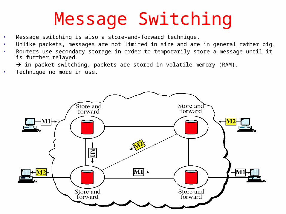
Message Switching• Message switching is also a store-and-forward technique.• Unlike packets, messages are not limited in size and are in general rather big.• Routers use secondary storage in order to temporarily store a message until it is further relayed.
in packet switching, packets are stored in volatile memory (RAM).• Technique no more in use.