THE PERFORMANCE OF TIMBER STRUCTURES, ELEMENTS AND...
19
Enjily V. - The performance of timber structures, elements and components. COST Action E24, Oct. 2001, Denmark. 1 THE PERFORMANCE OF TIMBER STRUCTURES, ELEMENTS AND COMPONENTS Vahik Enjily Centre for Timber Technology and Construction (CTTC) Building Research Establishment (BRE) UK 1. INTRODUCTION This paper has been prepared for COST Action E24 for consultation and information purposes only. The main aim of this paper is to highlight and summarise typical behaviour and performance of timber structures, elements and components. This paper includes the following topics: • Behaviour of medium-rise timber frame buildings in disproportionate (progressive) collapse. • Whole building racking stiffness of medium-rise timber frame buildings. • Racking resistance of wall panel elements. • Performance of trussed girder components under eccentric loading. • Performance of trussed rafter roofs containing a 3-ply girder (based on original design) The information given in this paper is not intended to be exhaustive. It is intended to highlight typical performance and modes of failures which should be considered in the reliability analysis of timber structures. 2. BEHAVIOUR OF MEDIUM-RISE TIMBER FRAME BUILDINGS IN DISPROPORTIONATE (PROGRESSIVE) COLLAPSE 2.1 Summary of the TF2000 project The well documented Timber Frame 2000 project provided a six-storey experimental timber frame building (Figures 1, 2 & 3) for the sole purpose of investigating the performance and economic prospects of medium-rise timber frame buildings in the UK. The majority of associated research projects conducted on this building have been completed and the results published and presented on different international forums. Figure 1: The Six-storey TF2000 Building at BRE Cardington Timber frame buildings of up to four storeys are being used quite extensively in the UK, however no comprehensive design rules exist for five storeys or more. As a result BRE and TTL carried out a joint feasibility study [2] on such buildings and subsequently built a six storey experimental building in
-
Upload
trinhnguyet -
Category
Documents
-
view
227 -
download
0
Transcript of THE PERFORMANCE OF TIMBER STRUCTURES, ELEMENTS AND...

Enjily V. - The performance of timber structures, elements and components. COST Action E24, Oct. 2001, Denmark.
1
THE PERFORMANCE OF TIMBER STRUCTURES, ELEMENTS ANDCOMPONENTS
Vahik Enjily Centre for Timber Technology and Construction (CTTC)
Building Research Establishment (BRE)UK
1. INTRODUCTIONThis paper has been prepared for COST Action E24 for consultation and information purposes only.The main aim of this paper is to highlight and summarise typical behaviour and performance oftimber structures, elements and components.
This paper includes the following topics:• Behaviour of medium-rise timber frame buildings in disproportionate (progressive) collapse. • Whole building racking stiffness of medium-rise timber frame buildings.• Racking resistance of wall panel elements.• Performance of trussed girder components under eccentric loading.• Performance of trussed rafter roofs containing a 3-ply girder (based on original design)
The information given in this paper is not intended to be exhaustive. It is intended to highlight typicalperformance and modes of failures which should be considered in the reliability analysis of timberstructures.
2. BEHAVIOUR OF MEDIUM-RISE TIMBER FRAME BUILDINGS INDISPROPORTIONATE (PROGRESSIVE) COLLAPSE
2.1 Summary of the TF2000 project The well documented Timber Frame 2000 project provided a six-storey experimental timber framebuilding (Figures 1, 2 & 3) for the sole purpose of investigating the performance and economicprospects of medium-rise timber frame buildings in the UK. The majority of associated researchprojects conducted on this building have been completed and the results published and presented ondifferent international forums.
Figure 1: The Six-storey TF2000 Building at BRE Cardington
Timber frame buildings of up to four storeys are being used quite extensively in the UK, however nocomprehensive design rules exist for five storeys or more. As a result BRE and TTL carried out ajoint feasibility study [2] on such buildings and subsequently built a six storey experimental building in
Enjily V. - The performance of timber structures, elements and components. COST Action E24, Oct. 2001, Denmark.
2
partnership with the UK industry and DETR. The feasibility study, construction of the experimentalbuilding and later testing of the building were all conducted as part of the Timber Frame 2000 project(TF2000) with the objective of providing the technical tools and commercial drivers for the safe andeconomic construction of medium-rise timber frame buildings in the UK.
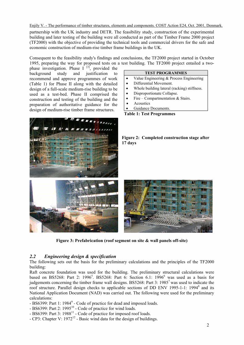
Consequent to the feasibility study's findings and conclusions, the TF2000 project started in October1995, preparing the way for proposed tests on a test building. The TF2000 project entailed a two-phase investigation. Phase I [3], provided thebackground study and justification torecommend and approve programmes of work(Table 1) for Phase II along with the detaileddesign of a full-scale medium-rise building to beused as a test-bed. Phase II comprised theconstruction and testing of the building and thepreparation of authoritative guidance for thedesign of medium-rise timber frame structures.
Figure 2: Completed construction stage after17 days
Figure 3: Prefabrication (roof segment on site & wall panels off-site)
2.2 Engineering design & specification The following sets out the basis for the preliminary calculations and the principles of the TF2000building: Raft concrete foundation was used for the building. The preliminary structural calculations werebased on BS5268: Part 2: 19965. BS5268: Part 6: Section 6.1: 19966 was used as a basis forjudgements concerning the timber frame wall designs. BS5268: Part 3: 19857 was used to indicate theroof structure. Parallel design checks to applicable sections of DD ENV 1995-1-1: 19948 and itsNational Application Document (NAD) was carried out. The following were used for the preliminarycalculations: - BS6399: Part 1: 19849 - Code of practice for dead and imposed loads. - BS6399: Part 2: 199510 - Code of practice for wind loads. - BS6399: Part 3: 198811 - Code of practice for imposed roof loads. - CP3: Chapter V: 197212 - Basic wind data for the design of buildings.
TEST PROGRAMMES• Value Engineering & Process Engineering• Differential Movement.• Whole building lateral (racking) stiffness.• Disproportionate Collapse.• Fire – Compartmentation & Stairs.• Acoustics• Guidance Documents.
Table 1: Test Programmes

Enjily V. - The performance of timber structures, elements and components. COST Action E24, Oct. 2001, Denmark.
3
Strength Class C16 to BS EN33813 was used throughout the calculations, in order to ensure that thetests on the structure will demonstrate the performance of such a building when using softwood fromany suitable supply source (including the UK.). In consideration of the desirability of minimisingdifferential movement, a decision was taken to designate special target moisture content at the time oferection. This was 12% ± 2% for floors and 18% ± 2 for walls. The following general specifications for key elements were proposed and agreed (Figure 4):• The ground floor is notionally a concrete slab-on-
ground. Walls consist of two layers of plasterboardwith a vapour control layer and 89 x 38 mm C16timber studs with mineral wool insulation in between.The sheathing is 9 mm OSB, Type F2 (OSB3). Thecavity is 60 mm with single leaf brick cladding tiedwith stainless steel ties to timber frame.
• Internal load bearing walls consist of C16 timberstuds with two layers of plasterboard and 9 mm OSB,Type F2 sheathing to one side, where needed for windbracing. The internal non-load bearing walls consistof C16 timber studs with one layer of plasterboard toeach side. The compartment walls are twin leaf withC16 timber studs and mineral wool insulation inbetween. OSB Type F2 sheathing is used where wind resistance is required.
• Compartment floors consist of two layers of plasterboard ceiling lining and C16 joists withmineral wool in between. OSB Type F2 is used as a floor deck. Floating floors containproprietary resilient battens with plasterboard and Type P4 chipboard.
• The roof is the trussed rafter type with hipped ends supporting concrete interlocking tiles.
More information is given in reference 14.
2.3 Robustness and Disproportionate Collapse Robustness is the principle of providing additional strength against potential and unforseen events. Itis not a case of over-design but a primary responsibility of a building engineer to produce a designsolution that can resist catastrophic failure that might occur due to small incidents or misuse. Theengineer avoids over design through skills in selecting design solutions that are economic andpractical to ensure that people in a building are safe within the designated area of influence. Poorrobust design can be over cautious and impractical to the scale of the project. While there are UKbuilding regulation requirements for the minimum levels of robustness, additional robustness may bejustified in the value of the building: for example the cost associated with redress of damage andsubsequent restoration.
The forthcoming Euro Codes formally recognises robustness as a design process and clearly clarifiesthat accidental load conditions are associated with design and material factors less onerous than thoseused in normal design process. The primary Euro Code - EC1: Part 1 addresses all buildings andpresents alternative methods of approach to limit or avoid poor robustness design:
• Avoiding, eliminating or reducing the hazards which the structure may sustain.• Selecting a structural form which has low sensitivity to the hazards considered.• Selecting a structural form and design that can survive adequately the accidental removal of
an individual element or a limited part of a structure, or acceptable localised damage.• Avoiding as far as possible structural systems which may collapse without warning.• Tying the structure together.
Figure 4: Brick cladding under construction

Enjily V. - The performance of timber structures, elements and components. COST Action E24, Oct. 2001, Denmark.
4
The UK building regulations addressees robustness under the term disproportionate collapse. To-datethe UK building regulations Part A- Structure, requires that “The building shall be constructed sothat in the event of an accident, the building will not suffer collapse to an extent disproportionateto the cause”. It also requires (to-date) that buildings only above four storeys are to include in thedesign process a check to ensure robustness of the structure against collapse or allow localiseddamage when subjected to a defined level of accidental damage. It is being considered however thatthe disproportionate rules will be applied to all heights of buildings within the near future.
The building regulations accept localised damage as being inevitable under certain accidents butlimits this to 15% of the area of the storey or 70m2 (which ever is less) within that storey andimmediately adjoining storey above.
It is not important to understand what the accident is but rather that defined length or elements of thestructure that can be removed in turn and to investigate theoretically what the consequence of theremoval does to the remaining structure.
The timber frame fabrication process, both volumetric and panel construction, provides a significantamount of connectivity through site and factory nailing. The “common sense” approach is that timberframe panels offer significant inherent robustness and capacity to span over removed panels –particularly in the short term periods of accidental damage. Hence it is appropriate for timber frameconstruction to addresses robustness by the concept of notional removal of defined structural panellengths – one at a time on each storey level and in turn check the stability of the remaining structure.
What are the defined timber frame structural elements to be removed?• Load bearing walls or a column/post• Wall length is length between intersecting walls (party walls, return walls, etc.)• Panels between column/post• Minimum length of 2.4m
Collapse in disproportionate checking procedures is considered to be failure of structural elementswhen the following is exceeded:• Floor/wall vertical deflections greater than L/30 (including total collapse) or if the layout and
function of the element under consideration becomes so high that the members are over stressedor that safe egress from the building is not possible.
• Once a ‘support member’ has been removed, one at a time on each storey in turn, then the area offailure of the storey and immediate adjacent storeys is limited to the lesser of:A 15% of the floor area of the storeyB 70m2
Area of storey = the whole building storey floor area (building foot print)
England/Wales and Scotland/Northern Ireland Building Regulations and Standards all refer to theneed for disproportionate collapse robustness for buildings above four storeys. The objective of thispart of the programme of tests was to enable an evaluation of the actual behaviour of the TF2000building when selected vertical load bearing wall panels are removed. This evaluation was to verifythat the inherent stiffness of cellular platform timber frame construction could provide the necessaryrobustness so that, in the event of an accident, the building would not suffer collapse to an extentdisproportionate to the cause. This is best achieved by designing in such a way that a beam, columnor section of wall can be removed without the structure above collapsing (although damage to thebuilding is allowed). To achieve this, beams are incorporated within floor depths over external walls,or the walls themselves are made to act as beams.

Enjily V. - The performance of timber structures, elements and components. COST Action E24, Oct. 2001, Denmark.
5
The building was loaded using weighedsandbags positioned on each floor abovethe full flat area where the tests werecarried out in similar manner to that setout in the other material codes forchecking disproportionate collapse. Thefollowing rules were defined for theTF2000 building:
• The horizontal length of any load-bearing wall to be notionallyremoved in any given instance is thelength between intersectinginternal/return walls or specialvertical support system.
• A full analytical review of the building was undertaken to predict the effect of removing each ofthe load bearing wall panels so that the ‘worse case’ could be chosen for the tests. For maximumvertical load effects and practicality,ground floor panels were chosen.
• Two main areas of the building weresubjected to the notional removal ofwalls, namely: (a) an internal wall and(b) a part of an external wall, betweenreturn walls (Figure 5).
• The agreed limit level of serviceability(a function of the practical limit ofdeflections) for floor spans of 3600mmwas chosen to be 300mm (approx.L/12).
Table 2 shows a summary of the resultsand more information can be found inreference 17.
2.3.1 Summary of the Principle of Disproportionate Collapse Check• To ensure that safe egress of people can be achieved when a building has a structural problem
(however caused) which is not disproportionate to the cause.• To ensure that the building can sustain safe access for temporary propping which might be
considered essential for public safety.• Stability of the building under the above two conditions shall be ensured for a minimum 24 hour
period.
Cladding - • Cladding is seldom structural although failure through total collapse would be a risk to public
safety.• The area of masonry based cladding considered acceptable for collapse is 2.25 times the storey
height. Guidance on this is available in the masonry code BS 5628.• The area of timber cladding or other lightweight cladding shall be the same as the timber frame.
Structural loading under the check -• Full dead load (including any finishes or fixed plants).• 1/3 improved floor load.• 1/3 imposed roof load.• No wind load checks are required.
Duration Vertical Deflection (mm)Floor Wall above
For internal wall removed:30 minutes 13 No significant movement4 hours 19 No significant movement20 hours 26 No significant movement
For external wall removed:30 minutes 2.5 1.24 hours 3.7 2.420 hours 4.0 2.6No cracking of masonry cladding
Table 2 - Summary of disproportionate collapse results
Figure 5: Disproportionate Collapse Test

Enjily V. - The performance of timber structures, elements and components. COST Action E24, Oct. 2001, Denmark.
Structures below timber frame -Where ground or other lower storeys are constructed from other structural materials, i.e. concrete,masonry or steel frame. The effect of loss of support from the underlying structure on the timberframe shall also be considered. Co-ordination of the removal or deflection of support structure mustbe allowed for the timber frame check.
Timber design issues under robustness design process -In line with the principles of the Euro Code principles the design strength of timber can be taken witha duration of load factor of double the working stress values eg for BS5268 part 2 design code K3=2for stress checking. In addition mean MOE values may be assumed for single/double members. Wheresteel and timber connections are used, twice basic working stress design values may be adopted.
Wall panels
Most wall panels have sufficient stiffness created by the plasterboardmoderate distances. A structural check on a theoretical deep beam action loads will easily demonstrate this assuming of course that there is continbottom plates (Figure 6).
In some applications additional support to walls and floors can typically bdetailing of timber frame in the form of continuous or cantilever heade(Figure 7).
Panel spans overnotionally removed panel
Figure 6: Elevation panels spanning over a gap
Panel Spans across ortension/compression ties tomain structure
6
/timber sheathing to spanof a panel under accidentaluity of the panel’s top and
e found within the typicalr joists and/or rim beams

Enjily V. - The performance of timber structures, elements and components. COST Action E24, Oct. 2001, Denmark.
7
Tests at BRE Cardington have shown that floors subject to loss of ‘central’ support and where built into the perimeter walls (as in floor cassettes in platform frame) will have significant built-in supportfrom the walls running parallel to the joist span. This was shown to occur in 2:1 aspect ration ofwidth to span.
If the walls provide support to floors then a check on the capacity to hold the floor through specifiedskew nailing shall be made or hangers provided to support the resultant loads.
Where a discrete column is used then this shall be designed as a key element in the same manner assteel framed buildings and the following design criteria should be adopted:
• The column shall be designed under accidental loads and deflection limits (L/30) to resist34kN/m2 over the length of the column.
• No lateral restraint provided by the removed panel – but restraint may be available fromothers that are not within the area of influence of the notionally removed panel.
2.3.2 ConclusionsIt was recognised that it is not simple to develop mathematical models for engineers to checkcompliance to disproportionate collapse criteria. More reliability-based design research is needed toadvance engineering models for prediction of actual behaviour.
More information can be found in reference 17.
Header joist/Rim beam spans across “gap” – support oflaps to adjacent /transverse panels or designated columns
Figure 7: Elevation on joist/rim beam spanning over a gap

Enjily V. - The performance of timber structures, elements and components. COST Action E24, Oct. 2001, Denmark.
8
3. LATERAL STABILITY
3.1 Whole Building racking stiffness of medium-rise timber frame buildingsOne of the many items of interest in the construction of the TF2000 is the contribution of the variousbuilding elements (e.g. plasterboard, brick cladding, etc.) to the overall stiffness of the structure.However, measuring the overall stiffness of a six-storey building is not a simple task, and dynamictesting was selected as an indirect way of determining the required information.
Measurements of the frequencies of the building were made using a laser system (Figure 8) tomonitor the ambient response of the structure, i.e. its natural vibration caused by air movement withinthe BRE Cardington Hangar. These measurements are processed to produce an autospectrum, whichis used to identify the frequencies of the modes of vibration. The laser has the advantage that themeasurements can be made remotely from the building.
More comprehensive forced vibration tests (Figure 8) were also undertaken at a number of key stages.These are used to determine all of the characteristics of the fundamental modes of vibration, i.e.frequency, mode shape, stiffness & damping. This provides detailed information but required the useof a vibration generator attached to the building.
Figure 8: Stiffness measurements of the TF2000 building
The following stages show the overall tests carried out:
Stage I - Timber frame alone (blocks of flats, stairs, roof, roof tiles)Stage II - Stiffness of timber frame plus all plasterboard wall and ceiling liningsStage III - Stiffness of completed building including masonry cladding
The following analyses were carried out: • Lateral stiffness of timber frame only• Lateral stiffness of timber frame and plasterboard linings• Lateral stiffness of whole building (with brick cladding)
The results show that the addition of plasterboard linings increased the stiffness by a factor of 3.3,indicating that these items play an important role in the overall stiffness of the structure at that stage.The addition of the brick cladding introduced a further overall stiffness of the structure by a factor of5.3 (to a total factor of 17.5 over the original timber frame). These results are being analysed forcodes and standards and amendments will be made to the codes in due course. More detailed resultsare given in reference 16.
Enjily V. - The performance of timber structures, elements and components. COST Action E24, Oct. 2001, Denmark.
9
3.2 Racking resistance of wall panel elementsIt must be noted that the above tests on the TF2000 building, given in section 3.1, did not includestrength tests. However, the strength test can be simulated by the element tests given below:
The most common type of timber frame walls constructed in the UK usually consists of a timberframe (studs, and top and bottom rails) sandwiched between panel products sheathing andplasterboard linings. BS5268: Part 6 gives all the relevant requirements for the design, testing andconstruction of timber frame walls.
The performance of timber frame wall panels in racking is not easily amenable to conventionalmethods of analysis based on material characteristics and principles of structural engineering. It istherefore necessary to assess the performance of wall panels before any attempt is made for analysis.It is essential that such a method is able to take account of the numerous variables relating to loads,materials, fixings and panel configuration. This part of the paper summarises typical types of failuresin timber frame walls subjected to racking loads.
Types of failure (Figure 9):• Lateral shear failure of nails along with their pull-out from the bottom rail at the bottom corner of
the panels (on the loading side). • Embedment of nail heads into the sheathing and pull-through • Cracking of the bottom timber rail.• Lateral shear failure of sheathing at nail positions• Tension and compression failures of sheathing• Buckling of the sheathing within the studs.

Enjily V. - The performance of timber structures, elements and components. COST Action E24, Oct. 2001, Denmark.
10
Figure 9: Typical types of failure in racking wall panels

Enjily V. - The performance of timber structures, elements and components. COST Action E24, Oct. 2001, Denmark.
11
4. PERFORMANCE OF TRUSSED GIRDER ROOFS
4.1 Trussed girder components under eccentric loadingThis part of the paper describes the results of an experimental and theoretical investigation into theperformance of multi-ply trussed girders under eccentric loading. Failure modes and safety indicesare identified on a range of girders by means of full-scale laboratory testing designed to closelysimulate practical conditions. Current design deficiencies are highlighted and new design proposalsare made, based upon test results and theoretical studies of the stress conditions present in suchsituations (note that BS5268: Part 3 already has adopted the proposed design rules).
In trussed rafter roof construction it is common practice at roof intersections to use trussed girders tosupport in-coming trusses, via steel shoes connected to the bottom chord of the girder (Figure 10).This eccentric load can create significant torsional and bending forces on the girder bottom chordwhich had been ignored in UK design or detailing practice. Anti-split plates or rotational restraintbrackets fixed to the girder bottom chord are details which are known to be in use in some countriesaround the world, but their application seems to be somewhat arbitrary.
The main objective of the research was to investigate the behaviour and safety levels present in multi-ply girders under eccentric loading. All the girders were designed according to then current Britishdesign practice, based on BS5268: Part 3 (BSI, 1985) and BS5268: Part 2 (BSI, 1991). The previousdesign practice did not take into account the eccentric loading effect on girders, and was based on allplies in a multi-ply girder carrying equal proportions of the load.
The plies of the 3-ply girders were nailed together while the plies for the 4-ply girders were boltedtogether. These fixings were therefore designed to transfer 2/3 and 3/4 of the total load, for 3- and 4-ply girders respectively. The total design load for the 3-ply girder was 73.3 kN while for the 4-plygirder it was 93.6 kN.
A test programme was devised to determine types of failure and their causes, and any shortcomings inthe design, construction and manufacture of such girders. All the tests carried out to-date and theirresults are described in more detail in the appropriate BRE Client Reports (Enjily and Tarr 1993 &1994). A brief description of the test method, tests and summary of major test results is given below:
The eccentric loads were applied to the bottom chord of the girders through standard 1.2 mm thickmetal girder shoes Type TW961, 38 mm wide and fixed to the bottom chord by means of 3.0 x 75mm square twisted sheradised, plain head nails. Loading was by means of 3.9 m long steel loadingarms, at 600 mm centres, which contained softwood timber members of 35x100 mm placedunderneath and parallel to the loading arms. The timber members of the loading arms were seated inand nailed to the standard girder shoes fixed to the bottom chord of the girders. These timbermembers were used to simulate the incoming trusses in practice, which provide some lateral stabilityto the bottom chord of girders. The ends of these timber members were placed at 0-6 mm from theback of the shoes in order to simulate typical positioning tolerances on site.
The application of the load was by means of 12 hydraulic jacks, at 600 mm centres. The jacks werepinned at the steel loading arms and their supports. A timber brace was attached perpendicular to thesteel loading arms (parallel and near to the girders tested) for load sharing purposes. Intermediatesupport to the timber members of the loading arms was also provided 2.3 m from the girders; this wasto simulate the stiffness of the incoming trussed rafter roof and to prevent excessive bending of thetimber members of the loading arms.
The loads applied to the girders were measured by means of two pairs of load cells, each pair beingpositioned at the supports. Potentiometers, connected to a data acquisition system, were used tomeasure the vertical deflections, rotations, and out-of-plane movement of the top and bottom chords,and the opening up of the plies due to torsion, as well as deflections and rotations of the shoes.

Enjily V. - The performance of timber structures, elements and components. COST Action E24, Oct. 2001, Denmark.
12
4.1.1 Tests Overall, 16 girders were tested, three of which were 4-ply girders and the remainder being 3-plygirders. Four of the 3-ply girders were used in mock-up tests, each time improving the method oflaboratory simulation to that in practice. All the instruments and the data acquisition systems werealso checked for accuracy during these mock-up tests. The following tests are annotated A and B for3-ply and 4-ply girders respectively: The average moisture content of girders during testing was 12%.
Tests A1 and B1 : These tests were treated as datum tests and represent typical examples of designsolutions currently used in the UK. The girders in these tests were loaded eccentrically, with norotational restraints at the bottom chord of girders. Standard girder shoes were used at the bottomchords. The girders had 35% and 45% plate bite sizes at the bottom chord nodal points, for the 3-ply(Test A1) and 4-ply (Tests B1) girders respectively.
Tests A2 and B2: The test method was identical to that used in Tests A1 and B1 respectively. On thisoccasion the girders' bottom chords were restrained by noggings at the back of the girders. Thegirders were identical to those in Tests A1 and B1 respectively. Standard girder shoes were used atthe bottom chord of the girders.
Tests A3 and B3: These tests, were concentric tests. The concentric load was applied to the bottomchord. The girders were identical to those used in Tests A1 and B1 respectively.
Tests A4 and A5: The test method was identical to that used in Test A1. The girders had a 75% platebite size at their bottom chord nodal points. Standard girder shoes were used at the bottom chord ofthe girders.
The only difference between the girders in Tests A4 and A5 was that the girder in Test A5 had aquarter point plate width of 76 mm rather than 63 mm as in Test A4. None of the girders hadrotational restraints at their bottom chords.
Test A6: The method of test was identical to that used in Test A1. The girder in this test had restraintsof plywood decking (noggings and plywood nailed together and then nailed to the bottom chord ofthe girder. The girder had 75% plate bite sizes at the bottom chord nodal points. Standard girder shoeswere used at the bottom chord.
Test A7: The method of test was identical to that used in Test A1. The girder had a newly designedtype of shoe restraining the bottom chord. The girder had a bottom chord plate bite size of 35%.
Test A8: The method of test was identical to that of Test A1. The girder had a bottom chord plate bitesize of 75%. The girder had standard type shoes plus a new type of strap restraining the bottom chord.
Test A9: The method of test was identical to that of Test A1. The girder had a newly designed type ofshoe restraining the bottom chord. The girder had a bottom chord plate bite size of 75%.
4.1.2 Summary of the results • The main types of failure were:
- Tests A1 to A5 & B1 to B3:- Tension perpendicular to the grain of the timber in the vicinity of the bottom boundary of the
bottom chord nodal plates (Figure 10). - Test A6:- Rafter buckling failure. - Tests A7 to A9:- More of a shear failure than tension perpendicular to the grain failure in the timber at the
bottom chord nodal points.

Enjily V. - The performance of timber structures, elements and components. COST Action E24, Oct. 2001, Denmark.
13
• The opening up of plies, both in the top and bottom chords, proved to be insignificant due to theconnections fixing the plies together and the connections of the shoes to the bottom chord.
• The out-of-plane movement of the top chords proved to be insignificant for the tests with factorsof safety of less than 2.0. However, for tests with factors of safety of more than 2, buckling of thetop chords was taking place without actual failure of the top chords occurring (except in Test A6where failure did occur).
• The failures were more due to torsion than bending of the bottom chord of the girders. Therefore,torsion and tension (perpendicular to grain) grade stresses of timber should be investigated so thatappropriate permissible stresses of timber can be used in the design.
• Investigation should be carried out as to what proportion of the eccentric loading is resisted byeach ply of the girders.
• The size and position of the punched metal plates at the nodal points play an important role in theload-carrying capacity of girders. The load-carrying capacity of girders, under eccentric loading,may be partially increased by extending punched metal plates towards the bottom edge of thebottom chord. Therefore, consideration should be given to extending the punched metal plateconnectors towards the bottom edge of the bottom chords to enhance the load-carrying capacityof girders by delaying as long as possible the type of failure obtained in the tests until an adequatedesign method has been developed.
• Consideration should be given to preventing (as much as possible) the rotation of the bottomchord of girders in practice (by the provision of adequate relevant bracing in the roof structure)until an adequate design method is developed.
• Shoes proved to be adequate regarding their overall strength and serviceability criteria for theactual failure loads obtained. The shoes, and their connections to both the girders and theincoming trusses are one of the important factors to prevent rotation of the bottom chord ofgirders. Therefore, adequate nailing of the shoes both to the girders and the incoming trussesshould be carried out in practice. In addition, certified standard girder shoes (wrapped-round)must always be used to preclude the opening up of plies and to provide for the adequate transferof the eccentric loads to the bottom chord, as proved by the tests.
• The type of girder used in practice is obviously important. The bottom chord of Fink type girdersare not anticipated to perform as well in torsion as Howe type girders because of their layout;More nodal points at the bottom chord would result in a better torsional stiffness (better load-carrying capacity of girder) of the bottom chord. Therefore, various types and spans of girdersneed to be tested, incorporating all the areas highlighted in this report as well as any necessarycriteria for the development of the theoretical design method and its verification.
• The stiffness of the incoming trussed rafter roofs and their connections to girders are two of theimportant factors to prevent rotation in the bottom chord of the girders in practice. From theresults it can be deduced that the existing girders in service may have a factor of safety of morethan 1.0 due to the stiffness of the incoming roofs (provided that the standard of workmanship forthe construction of the roof is at least as good as that used in the laboratory). However, it must besaid that the precise value of this factor of safety cannot be determined unless a full-scale test iscarried out. It is not believed that a factor of safety 2.25 (required by the Code2) or more can beachieved because of the type of failure which depends on the tension capacity perpendicular tograin of timber. Therefore, the stiffness of the incoming roofs (especially the bending stiffness oftheir ties) and the bracing of the girders are important factors to be considered by designers sothat to prevent, if only partially, the rotation of the bottom chord of girders.
• Adequate longitudinal bracing (parallel and close to the girders near the point of application of theeccentric load) should be considered in the incoming roofs for additional load sharing purposes.
• The gap between the incoming trusses and the back of the shoes should be kept as small aspossible (not more than 6 mm) to prevent excessive eccentricity.
• Inevitably, some stepping of plies in multiply girders takes place during and after manufacture,causing the plies not to bear fully on the supports. Any bearing failure at the supports would notbe critical provided that the distance between the lower edge of plate (located over a point ofsupport) and the lower edge of the member in contact with the support, is at least that specified inthe Code2. Therefore, girders should ideally bear fully on their supports by consideringconstructional provision to overcome the stepping effect.
Enjily V. - The performance of timber structures, elements and components. COST Action E24, Oct. 2001, Denmark.
14
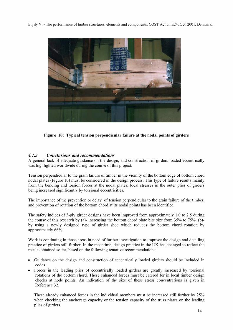
Figure 10: Typical tension perpendicular failure at the nodal points of girders
4.1.3 Conclusions and recommendations A general lack of adequate guidance on the design, and construction of girders loaded eccentricallywas highlighted worldwide during the course of this project.
Tension perpendicular to the grain failure of timber in the vicinity of the bottom edge of bottom chordnodal plates (Figure 10) must be considered in the design process. This type of failure results mainlyfrom the bending and torsion forces at the nodal plates; local stresses in the outer plies of girdersbeing increased significantly by torsional eccentricities.
The importance of the prevention or delay of tension perpendicular to the grain failure of the timber,and prevention of rotation of the bottom chord at its nodal points has been identified.
The safety indices of 3-ply girder designs have been improved from approximately 1.0 to 2.5 duringthe course of this research by (a)- increasing the bottom chord plate bite size from 35% to 75%. (b)-by using a newly designed type of girder shoe which reduces the bottom chord rotation byapproximately 66%.
Work is continuing in those areas in need of further investigation to improve the design and detailingpractice of girders still further. In the meantime, design practice in the UK has changed to reflect theresults obtained so far, based on the following tentative recommendations:
• Guidance on the design and construction of eccentrically loaded girders should be included incodes.
• Forces in the leading plies of eccentrically loaded girders are greatly increased by torsionalrotations of the bottom chord. These enhanced forces must be catered for in local timber designchecks at node points. An indication of the size of these stress concentrations is given inReference 32.
These already enhanced forces in the individual members must be increased still further by 25%when checking the anchorage capacity or the tension capacity of the truss plates on the leadingplies of girders.

Enjily V. - The performance of timber structures, elements and components. COST Action E24, Oct. 2001, Denmark.
15
• A tension perpendicular to grain check should be carried out at all joints using rules similar tothose outlined in this paper. Where the component is loaded eccentrically these tension stressesmust be magnified considerably as indicated in Reference 32.
• Positive restraint to eccentrically loaded components can greatly improve their serviceability andstrength. New proprietary metal hanger designs need to be developed which offer engineers moreoptions.
• Since the effectiveness of torsional restraints is primarily dictated by their rotational stiffness,performance criteria need to be established for such restraints, based upon standard test methods.
• Until further research is carried out and/or design rules have evolved, trussed girder designersshould (if in any doubt) consider the provision of minimum plate bites of 75% and 50% oneccentrically and concentrically loaded girders respectively. Consideration should also be givenin the meantime to the provision of torsional restraint to girders via diaphragms or tensionstrapping in addition to conventional metal shoes.
• Care should be taken to ensure gaps between the incoming truss and the leading face of the girderare minimised during erection, and that any unavoidable gaps are filled by packing.
Practical implications Most timber roofs in the UK, and we would suspect most other parts of the world, have a corner turn,an intersecting roof, a hipped end or similar, where incoming trusses meet and are supported on agirder truss spanning in the other direction. Usually, the incoming truss reactions at these points aretransferred eccentrically to the girder bottom chord via proprietary metal shoes. From a limited studyof girder design and detailing practice worldwide, it seems that almost universally these shoesprovide little if any horizontal restraint to torsional rotation of the girder bottom chord.
The full-scale tests carried out under this research so far indicate that torsional strain can createlocalised load concentrations in the outer plies in the order of 2 and 3 times that assumed from aconcentric analysis for 3- and 4-ply girders respectively. Stress concentrations in the outer truss platesthemselves can be 25% higher still. This in turn can result in a reduction in the overall factor of safetyin such girders down to as low as 1.0; the limiting failure condition often being tension failure in theouter truss plates themselves, or tension perpendicular to grain in the timber immediately beneaththem.
Tension perpendicular to grain checks due to torsion are rarely, if ever, carried out at joints due tolack of adequate design rules or data. Those design rules that do exist (Ehlbeck, Gorlacher andWerner 1989, Noren 1981) relate to concentrically loaded joints and therefore do not apply directly.The notional restraints offered to girder bottom chord by some proprietary hanger designs are also oflittle comfort, since even full restraint (which demands considerable restraint forces) still leaves stressenhancements in the individual plies of the order of 1.5-2.0.
Eccentrically loaded girders must be designed for enhanced forces in the leading plies. Application ofthese enhanced forces must be coupled with a tension perpendicular to grain stress check at allappropriate node points. The empirical formulae given in Reference 32 may be used as a guide in theformulation of appropriate design rules. Designed torsional restraints can have marked improvementson the performance and safety of eccentrically loaded girders, and new forms of shoe specificallydesigned for this purpose can often prove cost-effective. Manufacturers and designers alike shouldconsider developing new girder truss shoe designs to suit this purpose.
Whilst this research has concentrated on eccentrically loaded trussed girders jointed with truss plates,its implications are likely to apply equally to all eccentrically loaded components jointed by any formof timber fastener.

Enjily V. - The performance of timber structures, elements and components. COST Action E24, Oct. 2001, Denmark.
16
4.1.4 Areas in need of further investigation - • More theoretical studies should be carried out on girders loaded eccentrically leading to
refinements in the design methods proposed in Reference 32. • Investigation should be continued as to what proportion of the eccentric loading is resisted by the
individual plies of girders.• The distribution of torsion, tension, shear and bending stresses at the bottom chord nodes of
girders needs investigating. In addition, the aspect ratio of the bottom chord of girders should beinvestigated for torsional stiffness.
• Investigations should be continued on the influence of the plate bite size on girder performance.• Torsion and tension (perpendicular to grain) grade stresses of timber should be investigated so that
appropriate permissible stresses for the timber can be used in the design. • Various configurations and spans of 3-ply girders still need to be tested, as well as single-ply,
double-ply and 4-ply girders loaded eccentrically.• A performance specification for rotational restraints needs to be determined based on an
established test method.• Girders carrying other incoming girders should be investigated where high local concentrated
loads are applied. • A full-scale roof test is needed to indicate safety factors for existing girders in service.• Similar research to this is required on other types of eccentrically loaded components, jointed with
other types of timber fastener.• More reliability-based design research is needed to advance engineering models for prediction of
actual behaviour.
More detailed information and results are given in BRE Client Reports (Enjily and Tarr, 1993 &1994) and Reference 32.
4.2 Full-scale trussed rafter roof containing a 3-ply girder based on the original design
This part of the paper pertains to an investigation into the in-built factor of safety of existing roofs inservice containing 3-ply trussed girders (based on the original design) under eccentric loading. Intrussed rafter roof construction it is common practice at roof intersections to use trussed girders tosupport in-coming trusses, via steel shoes connected to the bottom chord of the girder. This eccentricload can create significant torsional and bending forces on the girder bottom chord which was ignoredin UK design or detailing practice in the past before 1991.
During the investigation, design deficiencies were highlighted by means of a series of componentgirder tests under eccentric loads, simulating the laboratory test work as close as possible to that inpractice, results of which are reported in section 4.1. A major design deficiency was that of the lowfactor of safety in the component tests. However, girders in service are anticipated to have a higherfactor of safety than that obtained in the component tests due to the stiffening effect of other roofmembers. It was necessary to determine the extent of increase in the factor of safety of such girders ina roof structure for the sake of all the existing 3-ply girders in service prior to the onset of theinvestigation. Thus a full-scale test was programmed to ascertain an indication of the in-built factor ofsafety of existing roofs in service containing 3-ply girders. The results of this investigation wasincluded in BS5268: Part 3 for trussed rafter roofs. This part of the paper summarises and concentrates on the work carried out on a full-scale test of a 'L'shaped building with a Fink type trussed rafter roof and a 3-ply Howe type girder. A brief summaryof the layout of the full-scale building (roof), the programme of work, the method of full-scale test,the method of related component tests, the types of failure and their causes are given. Finally, anindication of the in-built factor of safety of a 3-ply girder in a typical full-scale roof is determined inaddition to the assessment of the factor of safety of roofs with suspended ceilings (ie withoutplasterboard ceiling).

Enjily V. - The performance of timber structures, elements and components. COST Action E24, Oct. 2001, Denmark.
17
4.2.1 The design and construction details The full-scale roof test and all the component tests were carried out at BRE, in Hall A (HeavyStructures Laboratory, Building 14) and the Timber Engineering Laboratory (Building 20.2)respectively. The building design, fabrication, erection and all the materials were provided by TRA.
The building was a single storey typical 'L' shaped bungalow. All the timber frame walls weredesigned and prefabricated with studs of SC3 (C16) timber and OSB sheathing of 9.0 mm thick. Thegirder in the roof was designed and detailed based on the methods used prior to the onset of theinvestigation into girder trusses. The roof trusses were designed based on BS5268: Part 3: 1985. Thefull-scale roof was 'L' shaped with 30o pitch Fink trusses and contained a Howe type 3-ply girder atposition where the roof changed direction. Extra studs were used underneath the girder (at eachsupport) as supports because of the large concentrated loads at these points. All the prefabricated rooftrusses had M75 (TR26) timber members. The Roof covering consisted of felt, battens andinterlocking concrete tiles. Bracing of the roof was typical to that in practice in accordance withBS5268: Part 3: 1985. The spans of the incoming trusses and the trusses parallel to the girder were10.06 m and 7.786 m respectively. The roof had normal plasterboard ceiling (12.5 x 1200 x 1200 mmsheets) with the required noggings of 38 x 45 mm. The plasterboard ceiling joints were not taped orfinished with a skim coat of plaster or with 'Artex' as this would have been non-beneficial due to itsdestruction during the loading of the ceiling ties. The plasterboard orientation was that of the normalpractice which changed direction (panel orientation) at the vicinity of the girder. Large openings wereprovided in the gable walls for access to the attic and inside of the building.
4.2.2 The outcome • The ultimate load of the roof (girder) was 127.3 kN giving a factor of safety of 1.63 for the design
load of 78.1 kN. • The ultimate load of the roof with suspended ceiling (ceiling load of not more than 0.25 kN/m2) is
assessed to be 104.386 kN giving a factor of safety of 1.53 for the design load of 68.462 kN. • Factors of safety of 1.63 and 1.53 are obtained for roofs with and without plasterboard ceilings
respectively. It has been concluded that although these factors fail the acceptance criteriaspecified in the BS5268: Part2, the shortfall should be accepted for the following reasons:(a). Science evolves, and practitioners cannot be blamed for past omission that was caused by a
problem neither originally understood or even apparent to the industry nor any research dataavailable at the time. However, should subsequent development work highlight a potentialproblem (as it has done) which is then ignored, the blame can be fairly attributed to thepractitioners made aware of that potential problem by the code or any other guidance.
(b). Before the ultimate failure, the roof will definitely exhibit very pronounced signs of distresswhich with common sense should be reported, checked and not be used;
(c). The ultimate load obtained is more than the required design load; this design load has a lowprobability of exceeding the 53% reserve. However, this does not imply that thepractitioners should adopt this senorio for the future roofs for the reason mentioned in 1above.
5. CONCLUSIONS
It is clear that when components and elements are considered in buildings, the three-dimensionaleffect plays a significant role in the performance and safety factor of timber structures. This three-dimensional effect increases the factor of safety of the elements and components in general, whichcurrently there is no means of it being considered in the design of timber structures.
It must also be said that the majority of the above modes of failure do not always take place inbuildings due to the three-dimensional effect. It would be beneficial if a reliability analysis could becarried out using a three dimensional modelling of timber structures. The structures that should be
Enjily V. - The performance of timber structures, elements and components. COST Action E24, Oct. 2001, Denmark.
18
considered are multi-storey timber frame buildings and bridges. In addition, elements such as roofs,floors and walls, along with their components, are also in need of reliability analysis.
REFERENCES
TF2000 Building
1. HMSO. 1990-1995. Building Regulations, Approved Documents & Building Standards. London,UK.
2. Enjily V and Mettem C J. 1995. “Medium-rise timber frame buildings: Disproportionate collapseand other design requirements”. BRE, UK.
3. Enjily V and Palmer S. 1996. “Timber frame 2000. Phase I: Summary of commercial andtechnical findings”. BRE, UK.
4. Palmer S and Enjily V. 1998. Benchmarking and Construction Process of the TF2000 building.COST-E5 Workshop proceedings, BRE, UK.
5. British Standard Institution (BSI). 1996. “BS5268: Part 2:- The structural use of timber. Part 2:Code of practice for permissible stress design, materials and workmanship”. London, UK.
6. British Standard Institution (BSI). 1996. “BS5268: Part 6: Section 6.1:- The structural use oftimber. Part 6: Code of practice for timber frame walls. Section 6.1: Dwellings not exceedingfour storeys”. London, UK.
7. British Standard Institution (BSI). 1985. “BS5268: Part 3:- The structural use of timber. Part 3:Code of practice for trussed rafter roofs”. London, UK.
8. British Standards Institution (BSI). 1994. “DD ENV 1995-1-1:- Eurocode 5:- Design of timberstructures. Part 1.1: General rules and rules for buildings (together with the UK NationalApplication Document)”. London, UK.
9. British Standard Institution (BSI). 1984. “BS6399: Part 1:- Loading for buildings - Code ofpractice for dead and imposed loads”. London, UK.
10. British Standard Institution(BSI). 1995. “BS6399: Part 2:- Loading for buildings - Code ofpractice for wind loads. BSI, London, UK.
11. British Standard Institution (BSI). 1988. “BS6399: Part 3:- Loading for buildings - Code ofpractice for snow loads”. London, UK.
12. British Standard Institution (BSI). 1972. “CP3: Chapter V: Part 2:- Loading for buildings - Codeof basic data for the design of buildings - Wind loads”. London, UK.
13. British Standard Institution (BSI). 1994. “BS EN 338:- Loading for buildings - Structural Timber- Strength Classes”. London, UK.
14. Steer P J. 1998. “Design of TF2000 Building”. COST-E5 Workshop proceedings, BRE, UK.15. Grantham R and Enjily V. 2000. “Differential movement between the brick cladding and timber
frame of the TF2000 building”. Proceedings of the World Conference on Timber Engineering,Whistler, British Columbia, UBC, Canada.
16. Ellis B R, Bougard A J, Enjily V and Palmer S. 1998. “Dynamic Testing and stiffness evaluationof the TF2000 building”. BRE, UK.
17. Milner M W, Edwards S, Turnbull D B and Enjily V. 1998. “Verification of the robustness of asix-storey timber frame building”. The structural Engineer, Volume 76/No 16, London, UK.
18. Lennon T, Bullock M & Enjily V. 2000. “The fire resistance of timber frame building”. BREReport No 79485-1, BRE, UK.
19. Lennon T, Bullock M & Enjily V. 2000. “Medium rise timber frame 2000 stair fire test”. BREReport No 200-711, BRE, UK.
20. Pitts G. 2000. “Acoustic performance of party floors and walls in timber framed buildings”. ISBN1900510243, TRADA Technology Report 1/2000. High Wycombe, UK.
GIRDER TRUSSES
21- V Enjily and K Tarr. A preliminary investigation into the behaviour and safety of timber girdertrusses. BRE Client Report CR30/93. 1993, BRE, Watford, U.K.
22- British Standards Institution. Structural use of timber. Part 3 - Code of practice for trussedrafter roofs. BS5268: Part 3: 1985, BSI, London, U.K.
Enjily V. - The performance of timber structures, elements and components. COST Action E24, Oct. 2001, Denmark.
19
23- British Standards Institution. Structural use of timber - Code of practice for trussed rafter roofs.BS5268: Part 3: 1985. BSI, London, 1985.
24- British Standards Institution. Structural use of timber - Code of practice for permissible stressdesign, materials and workmanship. BS5268: Part 2: 1991. BSI, London, 1991.
25- Enjily V & Tarr K. 1993, A preliminary investigation into the behaviour and safety of timbergirder trusses. BRE Client Report CR30/93, March 1993.BRE, UK.
26- Enjily V. & Tarr K. 1993. The effect of eccentric and concentric loads (applied on the bottomchord) on the load-carrying capacity of girders. BRE Client Report CR163/93), August1993.BRE, UK.
27- Enjily V & Tarr K. 1993, The effect of punched metal plate bite size and rotational restraints onthe load-carrying capacity of girders. BRE Client Report CR164/93), October 1993.BRE, UK.
28- Enjily V. & Tarr K. 1993, Rotational restraints for 3-ply girders. BRE Client Report CR248/93),December 1993.BRE, UK.
29- Enjily V. & Tarr K. 1994, Improvement in the load-carrying capacity of 3-ply girders. BREClient Report CR36/94), April 1994.BRE, UK.
30- Ehlbeck J., Gorlacher R. and Werner H. 1989. Determination of perpendicular-to-grain tensilestresses in joints with dowel-type fasteners. CIB-W18A Paper 22-7-2, September 1989, Berlin,GDR.
31- Noren B. 1981. Design of joints with nail plates (second edition) CIB-W18 Paper 14-7-1, May1981,Warsaw, Poland.
32- Enjily V and Whale L R J. The performance of trussed girders under eccentric loading. PTEC 94,The Third pacific timber engineering conference, Australia, 1994.
Wall panels
33- Enjily V. and Griffiths D R. The racking resistance of large wall panels. BRE Report CR119/95,July 1995, UK.
34- Enjily V. and Fewell A R. The effect of sub-standard nailing on the racking resistance ofplasterboard in wall panels. BRE Report N145/91, Dec 1991, UK.
35- British Standard Institution (BSI). 1996. “BS5268: Part 6: Section 6.1:- The structural use oftimber. Part 6: Code of practice for timber frame walls. Section 6.1: Dwellings not exceedingfour storeys”. London, UK.