Characterisation of Cotton Fibre-reinforced Geopolymer Composites

The performance of carbon fibre composites as ICCP anodes for reinforced concrete structures
VAN NGUYEN, Chinh, LAMBERT, Paul, MANGAT, Pal <http://orcid.org/0000-0003-1736-8891>, O'FLAHERTY, Fin <http://orcid.org/0000-0003-3121-0492> and JONES, Graeme
Available from Sheffield Hallam University Research Archive (SHURA) at:
http://shura.shu.ac.uk/8096/
This document is the author deposited version. You are advised to consult the publisher's version if you wish to cite from it.
Published version
VAN NGUYEN, Chinh, LAMBERT, Paul, MANGAT, Pal, O'FLAHERTY, Fin and JONES, Graeme (2012). The performance of carbon fibre composites as ICCP anodes for reinforced concrete structures. ISRN Corrosion, 2012, 1-9.
Copyright and re-use policy
See http://shura.shu.ac.uk/information.html
Sheffield Hallam University Research Archivehttp://shura.shu.ac.uk

1
The Performance of Carbon Fibre Composites as ICCP Anodes for
Reinforced Concrete Structures
ChinhVan Nguyen, Paul Lambert, Pal Mangat, & Fin O’Flaherty
Centre for Infrastructure Management, Materials & Engineering Research Institute, Sheffield Hallam
University, Sheffield, United Kingdom, S1 1WB.
Graeme Jones
C-Probe Systems Ltd, United Kingdom.
E-mail address: [email protected]
Abstract
A number of technologies have been developed to tackle steel corrosion in reinforced concrete. Of these,
cathodic protection (CP) has been proven to be one of the most widely applicable and cost-effective solutions.
In this study, the possible use of carbon fibre composites, which are primarily used to strengthen concrete
members, has been investigated as impressed current cathodic protection (ICCP) anodes. Carbon fibre has
been assessed in concrete and calcium hydroxide solution to determine their anodic characteristics in a
simulated aggressive environment. Two bonding mediums incorporating both epoxy and geopolymer have
also been investigated. The results demonstrate that epoxy resin can be used for bonding carbon fibre fabric
anodes to reinforced concrete structures while geopolymer is more effective for bonding carbon fibre
reinforced polymer (CFRP) rod into pre-formed grooves in the concrete surface. While there is some
dissolution of the carbon fibre, the dissolution of CFRP fabric is greater than CFRP rod. The dissolution of
carbon fibre anode appears to stablise after a period of time, dependent upon the size and shape of the anode
and applied voltage and current. Based on the present results, a maximum current density of 128mA/m2 of
reinforcing steel area is recommended for the operation of CFRP fabric anode and 64mA/m2 of reinforcing
steel area for CFRP rod anode. A number of larger scale application for CFRP anodes operating both as CP
anode and strengthening are presently being developed.
Keywords: Cathodic protection, carbon fibre, anode, concrete, epoxy, geopolymer, current, circuit resistance.
1. Introduction
Cathodic protection (CP) is a proven method of controlling corrosion in reinforced concrete through the
application of a small DC current [1-4]. This can be applied either galvanically (e.g. by the preferential
corrosion of zinc) or by an inert anode, referred to as impressed current cathodic protection (ICCP) [5-9]. In
atmospherically exposed reinforced concrete structures, the successful application of ICCP depends
significantly upon the selection of appropriate anode systems [10,11]. There are a number of anode systems
currently available, these include: conductive carbon loaded paints, thermal sprayed zinc, coated titanium
expanded mesh or mesh ribbon in a concrete overlay, coated titanium expanded mesh ribbon mortared in to
slots chased into the concrete, internal (discrete) anode and conductive cementitious overlay containing nickel
plated carbon fibre[12,11]. The properties of the anode materials need to be considered and researched
carefully to ensure they operate effectively during their required service life.
Cathodic protection systems require a level of monitoring, generally by reference electrodes, to assess how
well the system is controlling corrosion. For ICCP systems in reinforced concrete, the current can be adjusted
to the appropriate value to protect the steel reinforcement [13]. The effectiveness of ICCP depends greatly on
the correct operation of the anodes, their electrical conductivity for electrochemical process as well as their
service life or rate of consumption due to a number of environmental and operational factors. The anode

2
system is required to deliver sufficient current in order to provide adequate protection for the structures.
Therefore selecting the appropriate value of current contributes significantly to the minimisation or avoidance
of damage to the anodes due to excessive consumption, passivation or loss of bond with the concrete.
Carbon fibre composites as civil engineering materials are a relatively recent development. They have
previously been used in a wide range of mostly ‘hi-tech’ industries [14, 15, 16,]. It has been documented that
CFRP can be applied on the surface of concrete with little environmental degradation and that CFRP wraps
can, on their own, impede further corrosion of steel [17-21]. CFRP is an electrically conductive material,
however, only limited research has been carried out with respect to the electrical conductivity of carbon fibre
and the possibility of using such materials in the protection of steel from corrosion. Therefore, this paper
evaluates the electrical conductivity and other properties of CFRP when employed as an anode in an ICCP
system. The bonding medium used to embed the carbon fibre into the concrete has also been investigated.
2. Experimental Method
2.1 Materials
2.1.1 Epoxy adhesive
The epoxy adhesive was supplied by Sika Corporation (US). In this test, Sikadur300 adhesive was used,
which is a two-component 100% solids, moisture-tolerant, high strength, high modulus epoxy widely used in
CFRP strengthening applications. It is documented by the manufacturer that Sikadur300 is used as a seal coat
and impregnating resin for horizontal and vertical applications.
2.1.2 Geopolymer
A commercially available geopolymer developed at Sheffield Hallam University was used to bond the CFRP
rods to the grooved reinforced concrete beams. Chopped carbon fibres were added to the geopolymer at 1.5%
of volume in order to control shrinkage and increase the electrical conductivity of the mix. The compressive
strength of different compositions of geopolymer which were tested ranged from 44.4MPa to 52.0MPa at 28
days age.
2.1.3 Carbon fibre
A high strength, unidirectional carbon fibre fabric (type Sika Wrap Hex 103C, supplied in the UK by C-Probe
Systems Ltd) was used. In normal applications, the material is field laminated using epoxy resin to form a
carbon fibre reinforced polymer for the strengthening of concrete structures.
Carbon fibre rod (type Sika CarboDur, supplied in the UK by C-Probe Systems Ltd) was also used which is
designed for strengthening concrete, timber and masonry structures. The rods have very high strength, light
weight, high modulus of elasticity, are non-corrosive, and display excellent fatigue resistance.
2.2. Test Arrangement
2.2.1 Test in Ca(OH)2 and concrete electrolyte
A series of tests was established in which carbon fibre was employed as an ICCP anode with a range of DC
voltages applied. The aim was to identify the optimum range of currents that could provide adequate
protection to the steel reinforcement without causing significant damage to the carbon fibre anode. Prior to
conducting the tests, both the carbon fibre anode and steel bars were weighed and then subsequently
reweighed at the end of the test. The ICCP was established with the DC positive terminal connected to the
carbon fibre anode while the DC negative terminal was connected to the steel bars.
3
The DC voltage was maintained at 5V, 10V or 20V. The tests were run in the ambient laboratory environment
(temperature 20oC, RH=60±5%). The performance of carbon fibre anodes was evaluated by visual monitoring,
applied current and circuit resistance of the electrolyte with time. The schematic test arrangement is shown in
Figure 1. The test programme for carbon fibre anodes in saturated calcium hydroxyl solution and in concrete
is detailed in Table 1.
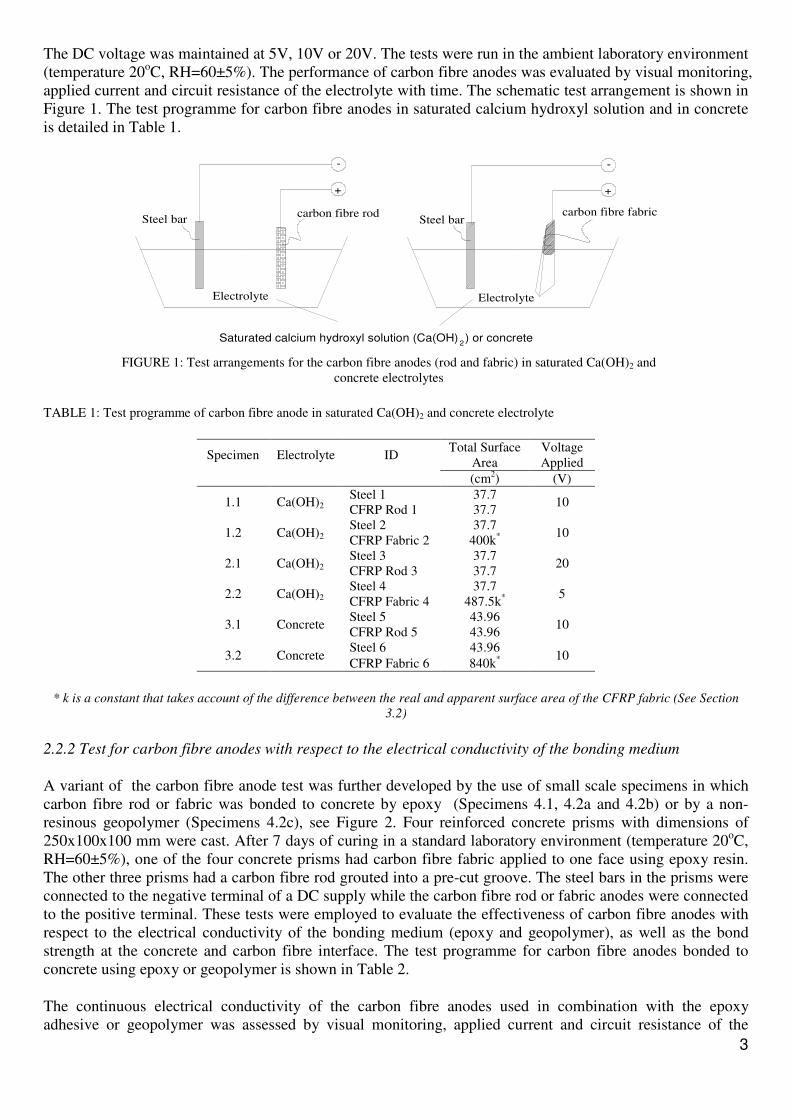
TABLE 1: Test programme of carbon fibre anode in saturated Ca(OH)2 and concrete electrolyte
Specimen Electrolyte ID Total Surface
Area
Voltage
Applied
(cm2) (V)
1.1 Ca(OH)2 Steel 1 37.7
10 CFRP Rod 1 37.7
1.2 Ca(OH)2 Steel 2 37.7
10 CFRP Fabric 2 400k
*
2.1 Ca(OH)2 Steel 3 37.7
20 CFRP Rod 3 37.7
2.2 Ca(OH)2 Steel 4 37.7
5 CFRP Fabric 4 487.5k
*
3.1 Concrete Steel 5 43.96
10 CFRP Rod 5 43.96
3.2 Concrete Steel 6 43.96
10 CFRP Fabric 6 840k
*
* k is a constant that takes account of the difference between the real and apparent surface area of the CFRP fabric (See Section
3.2)
2.2.2 Test for carbon fibre anodes with respect to the electrical conductivity of the bonding medium
A variant of the carbon fibre anode test was further developed by the use of small scale specimens in which
carbon fibre rod or fabric was bonded to concrete by epoxy (Specimens 4.1, 4.2a and 4.2b) or by a non-
resinous geopolymer (Specimens 4.2c), see Figure 2. Four reinforced concrete prisms with dimensions of
250x100x100 mm were cast. After 7 days of curing in a standard laboratory environment (temperature 20oC,
RH=60±5%), one of the four concrete prisms had carbon fibre fabric applied to one face using epoxy resin.
The other three prisms had a carbon fibre rod grouted into a pre-cut groove. The steel bars in the prisms were
connected to the negative terminal of a DC supply while the carbon fibre rod or fabric anodes were connected
to the positive terminal. These tests were employed to evaluate the effectiveness of carbon fibre anodes with
respect to the electrical conductivity of the bonding medium (epoxy and geopolymer), as well as the bond
strength at the concrete and carbon fibre interface. The test programme for carbon fibre anodes bonded to
concrete using epoxy or geopolymer is shown in Table 2.
The continuous electrical conductivity of the carbon fibre anodes used in combination with the epoxy
adhesive or geopolymer was assessed by visual monitoring, applied current and circuit resistance of the
Electrolyte
carbon fibre fabric
+
--
+
carbon fibre rodSteel bar
Electrolyte
Steel bar
Saturated calcium hydroxyl solution (Ca(OH) ) or concrete2
FIGURE 1: Test arrangements for the carbon fibre anodes (rod and fabric) in saturated Ca(OH)2 and
concrete electrolytes

4
electrolyte with time. The electrochemical performance of the CF rod or fabric anode was assessed in terms of
the current or corresponding CP circuit resistance required to maintain a constant voltage between the steel
cathode and carbon fibre anode. During operation of the ICCP, the voltage was maintained at 5V or 10V (See
Table 2) while the current applied to the anode was monitored.
TABLE 2: Test programme for carbon fibre anodes with respect to the electrical conductivity of the bonding medium
Specimens ID Bonding Medium
Total
Surface Area
Voltage
Applied
(cm2) (V)
4.1 Steel 7
Epoxy 157.0
5 Fabric 420k
*
4.2a Steel 8
Epoxy 157.0
10 Rod 94.2
4.2b Steel 9 Epoxy + chopped carbon
fibres
157.0 10
Rod 94.2
4.2c Steel 10 Geopolymer + chopped
carbon fibres
157.0 10
Rod 94.2
* k is a constant that takes account of the difference between the real and apparent surface area of the CFRP fabric (See Section
3.2)
FIGURE 2: Schematic test of electrical conductivity of carbon fibre fabric or rod bonded to concrete by different media
2.2.3 Application of carbon fibre working as ICCP anode to small beams
FIGURE 3: Application of ICCP CF anode to corroded reinforced concrete beams
Two pre-corroded reinforced concrete beams (150x100x900, see [22]) were cathodically protected using CF
fabric anodes (CFF1 and CFF2) while two others were cathodically protected using CF rod anodes (CFR1 and
CFR2). The CF fabric anodes were bonded to the concrete surface using epoxy. The CF rod anodes were
grooved into the concrete beams using geopolymer and chopped carbon fibre. ICCP was applied to the
corroded reinforced concrete beams by connecting the reinforcing steel to the negative terminal and the
CFRPs anode to the positive terminal of the multi-channel DC power supply. Testing was conducted in a
laboratory environment (temperature 20oC, RH=60±5%) in which the resistivity of the concrete is relatively
high (Figure 3). The applied currents were 10mA (corresponding to 128.4mA/m2 of steel area) for CF fabric
100
100
250CFRP Fabric
Anode
Concrete
Reinforcement
steel Φ10
-
+
250
100
100
+
-
Φ10
Reinforcement
steel
Concrete
CFRP Rod
Anode
CF fabric anode
CF rod anode

5
anode and 5mA (corresponding to 64.2mA/m2 of steel area) for CF rod anode which corresponded to the rest
potential of steel reinforcement. The ICCP systems were operated for 1100 hours. The current was checked
and the on and instant-off potential values for the embedded steel were recorded daily [22].
3. Result and Discussion
3.1 Visual Monitoring and Mass Loss
3.1.1 Test in Ca(OH)2 and concrete electrolyte
The performance of both the carbon fibre fabric and rod was observed daily during the tests. In each test with
the saturated calcium hydroxide solution electrolyte, hydrogen evolution was observed at the cathode (steel
bar). Simultaneously, it was observed that the carbon fibre anodes (fabric and rod) suffered from dissolution
(Figure 4).
FIGURE 4: Performance of steel and carbon fibre anodes in saturated Ca(OH)2 electrolyte
TABLE 3: Mass loss of carbon fibre anodes and steel bar cathodes- Test in Ca(OH)2 and concrete electrolyte
Specimen Electrolyte ID Weight Weight
Loss
Test
Duration Before Test After Test
(g) (g) (%) (hours)
1.1 Ca(OH)2 Steel 1 66.80 66.80 0.00
165.5 CFRP Rod 1 17.52 17.43 0.51
1.2 Ca(OH)2 Steel 2 67.51 67.50 0.01
165.5 CFRP Fabric 2 4.83 4.70 2.69
2.1 Ca(OH)2 Steel 3 67.21 67.19 0.03
249.0 CFRP Rod 3 17.78 17.68 0.56
2.2 Ca(OH)2 Steel 4 66.70 66.66 0.06
249.0 CFRP Fabric 4 6.13 6.04 1.47
3.1 Concrete Steel 5 82.73 82.73 0.00
888.0 CFRP Rod 5 21.12 21.05 0.33
3.2 Concrete Steel 6 82.34 82.34 0.00
888.0 CFRP Fabric 6 9.50 9.44 0.63
Dissolution of
CFRP fabric
Rod anode after
testing (10V)
Rod anode after
testing (20V) Calcarious layer
Dissolution of CFRP
rod anode

6
The steel bars and carbon fibre rod and fabric were subsequently washed, dried and reweighed to establish
their weight losses, as shown in Table 3 (test durations, in hours, are also given). The weight of steel bars
after testing was measured after removal of the calcarious layer deposited onto them by the action of the
cathodic polarisation. The results in Table 3 show that the weight loss of the carbon fibre rod anodes is 0.51%,
0.56% and 0.33% for Specimens 1.1, 2.1 and 3.1 respectively. The weight loss of the carbon fibre fabric
anodes is 2.69%, 1.46 % and 0.66% for Specimens 1.2, 2.2 and 3.2 respectively. It can also be seen from the
Table 3 that the weight loss of the steel bars in all test specimens is naturally at or around zero.
At the time corresponding to a cumulative current of 13mA applied to the carbon fibre rod anode (Specimens
3.1 and 3.2), a gaseous and yellow liquid deposit appeared around the rod. The pH of this material was in the
range of 1 to 2, confirming it is highly acidic. Concrete Society Technical Report No. 73 states that acid and
oxygen is generated during operation at the surface of anodic materials commonly used for the cathodic
protection of reinforced concrete due to the electrochemical reactions. It has been suggested that some anodes
may also generate chloride depending on the environment [12]. Therefore, the yellow discharge observed at
the carbon fibre rod anode and concrete interface is believed to result from both acid generation and the
3.5%NaCl (by weight of cement) which was added to the concrete mix. To confirm this, the deposit was
analysed using semi-quantitative XRF which showed that the deposit was around 60% chloride. The carbon
fibre fabric and rod anode after testing are shown in Figure 5.
FIGURE 5: Performance of carbon fibre (CF) anodes in concrete
3.1.2 Test for carbon fibre anodes with respect to the electrical conductivity of the bonding medium
The performance of the CF rod and fabric anodes was monitored and reported in Specimens 4.1, 4.2a, 4.2b
and 4.2c. In the case of the CF fabric, a gaseous and yellow liquid deposit again appeared on the surface of
the fabric, which may in turn be reducing the bond at the concrete-fabric interface. In comparison, there was
no sign of debonding at the CF Rod/geopolymer interface due to the electrochemical reaction. However, a
fine crack was observed at the concrete-geopolymer interface.
3.1.3 Carbon fibre working as ICCP anodes to small beams
After 985 hours of operation of the ICCP, a small gaseous and yellow liquid deposit appeared on the surface
of the CF fabric anode (Specimens CFF1, CFF2). This could, if more widespread, result in the de-bonding of
the CFRP fabric from the concrete interface. In the case of the CF rod (Specimens CFR1, CFR2), there was
no sign of damage or debonding problems [22].
3.2 The electrochemical performance of CFRP anode
The performance of an ICCP anode is represented by a number of parameters including consumption rate (the
rate in mass of anode consumed per ampere of current per year), efficiency (a comparison of actual anode
mass consumed to the theoretical mass required), steel polarization and CP circuit resistance (CR) [13].
CF fabric after testing
Imprint of CF fabric
in concrete
Dissolution
products of CF
rod absorbed at
the surface
CF rod after
testing

7
CP circuit resistance at time t is simply the quotient of the voltage, V(t) (volts), between the steel cathode and the anode and the CP current density, J(t), as in Equation 1 [13].
)(
)()(
tJ
tVtCR = (ohms.m
2). (1)
It is a DC measurement. While interfacial polarization effects contribute to CR, the changes that occur in CR
with time are expected to be largely related to resistive elements in the CP system and these elements would
be the same whether measured by DC or AC techniques.
The equivalent circuit resistance between carbon fibre anodes and steel cathodes in concrete consist of the
anode resistance at the anode-concrete interface, the electrolyte at the steel/concrete interface and the steel bar
resistance. The circuit resistance can be calculated as follows:
The current from the carbon fibre fabric anode passes through the electrolyte to the cathode. The area of
contact between the carbon fibre fabric anode and the electrolyte provides the passage for the current. This
area is not simply the plan surface area (Ss) since the mesh of the fabric has an influence on the contact area.
Therefore, the actual contact surface area of the anode is assumed as the plan surface area Ss multiplied by k,
where k is a constant value that takes account of the difference between the real and apparent surface area.
For the purpose of analysis and simplicity in this paper, it is not required to calculate an actual value for k.
From (1), Circuit resistance CR=Voltage/CP current density:
CF Rod: I
SV
S
I
VCR rod
rod
.==
CF Fabric: I
kSV
kS
I
VCR s
s
.==
3.2.1 Test in Ca(OH)2 and concrete electrolyte
The applied current versus exposure time and circuit resistance versus exposure time relationships for
different specimens are plotted in Figures 6,7,8 and 9.
FIGURE 6: Applied current versus exposure time (Ca(OH)2 electrolyte)
0
50
100
150
200
250
0 100 200 300
Cu
rre
nt
(mA
)
Time (hours)
CFRP ROD1(10V) CFRP FABRIC2(10V)
CFRP ROD3(20V) CFRP FABRIC4(5V)
(2)
(3)

8
It can be seen from Figure 6 that as the exposure time increases, the current passing to both the CF rod and
fabric anodes reduced significantly in the first of 50 hours from 104mA to 9mA and 142mA to 11mA for Rod
1 and Fabric 2, respectively. When operated at 20V the current passing to Rod 3 anode decreased
dramatically from 197mA to 25mA after 24.5 hours of exposure, with a further reduction to 19mA at which it
appeared to stabilise. Even when operated at 5V the Fabric 4 current dropped from 55mA to 5mA in the first
71 hours, and continued to fall to 3mA after 143 hours, where it remained stable until the test was terminated
at 249 hours. This is attributed to the dissolution of the CF rod or fabric anode into the calcium hydroxyl
solution, causing an increase in resistance.
FIGURE 7: Applied current versus exposure time (concrete electrolyte)
Figure 7 presents the applied current versus exposure time of CF rod 5 and CF fabric 6 in concrete electrolyte.
The current passing to both Rod 5 and Fabric 6 anodes reduced from 20mA to 9mA and from 23mA to 10mA
respectively in the first of 96 hours. The current continuously decreased to 1mA for Rod 5 anode and to 2mA
for Fabric 6 anode after 888 hours. This is attributed to the high resistivity of the concrete electrolyte, with the
possible dissolution of carbon fibre apparently not significantly affecting the resistance of the electrolyte.
After an initial period of operation, the current passing remained constant and the rate of dissolution of the CF
rod and fabric anodes was relatively low. Therefore, the currents passing remained relatively unchanged due
to the stable resistance. It would, therefore, appear that the CF rod and fabric anodes reach a stable state after
a specific time, dependent upon the type of anode and electrolyte. It is also noted that the rate of dissolution of
CF anode depends on both the magnitude of voltage applied and the type of CF anode employed.
FIGURE 8: The circuit resistance versus exposure time (Ca(OH)2 electrolyte)
0
5
10
15
20
25
0 200 400 600 800 1000
Cu
rre
nt
(mA
)
Time (hours)
CFRP ROD5 (10V) CFRP FABRIC6 (10V)
0
10
20
30
40
50
60
70
80
90
0 50 100 150 200 250 300
Cir
cuit
re
sist
an
ce (
Oh
ms.
m2
)
Time (hours)
CFRP ROD1(10V) (1/k)CFRP FABRIC2 (10V)
CFRP ROD3 (20V) (1/k)CFRP FABRIC4 (5V)

9
Figure 8 shows the circuit resistance versus exposure time relationships for specimen 1.1, 1.2, 2.1 and 2.2.
The Rod 1 anode circuit resistance increased moderately in the first period of 70 hours from 0.4 �.m2 to 6.3
�.m2. Thereafter, circuit resistance remained fairly constant at around 5.4 �.m
2 to 6.3 �.m
2. However, for
Fabric 2 anode, the circuit resistance rose significantly in the first period of 70 hours from 2.8k �.m2 to 50k
�.m2 and achieved the highest value of 66.7k �.m
2 after 140.5 hours of exposure. In addition, after 165.5
hours exposure, the mass loss of Fabric 2 anode was 2.69% compared to 0.51% for the Rod 1 anode.
Therefore, it can be concluded that the rate of dissolution of the CF fabric was significantly higher than that of
the CF rod for the same period. This may be due to the exposure areas of the CF fabric in the electrolyte
solution being much greater than that of the CF rod. Also the circuit resistance in the case of Fabric 4 anode
increased dramatically in the first 71 hours of operation from 4.4k �.m2
to 48.8k �.m2 and remained constant
for a further 48 hours before rising again to 81.3k �.m2
after 249 hours, presumably due to dissolution of the
CF fabric. By contrast, the circuit resistance of Rod 3 anode increased only slightly to 4 �.m2 after 249 hours.
It can be seen that CF fabric dissolved much more than the CF rod, despite the voltage applied to CF fabric
being lower. However, it should be noted that the CF rod anode suffered significant damage (see Figure 4).
Therefore, the magnitude of voltage applied to the anode needs to be considered carefully in order to avoid
damage to the anodes.
FIGURE 9: The circuit resistance versus exposure time (concrete electrolyte)
Figure 9 shows the circuit resistance versus exposure time relationships for Specimens 3.1 and 3.2. The
circuit resistance of Rod 5 anode has risen steadily from 2.2 �.m2 to 43.96 �.m
2. The trend of increasing
circuit resistance in the case of Fabric 6 anode is also observed. As previously discussed, it is difficult to
determine the actual value of surface area of CF fabric anode so only the trend can be shown. The circuit
resistance of carbon fibre fabric 6 anode increased moderately from 36.5k �.m2 to 420k �.m
2 after 575 hours
of exposure and then kept remaining the same at this value.
3.2.2 Test for carbon fibre anodes with respect to the electrical conductivity of the bonding medium
Specimens 4.1 consisted of CF fabric bonded to the surface and 4.2a of a CF rod bonded into pre-formed
grooves of the beams using epoxy. CP was applied to the reinforced concrete prism with the CF fabric or rod
employed as the anode. The CP was applied 7 days after the application of the CF anodes to the concrete
prisms.
0
50
100
150
200
250
300
350
400
450
0 200 400 600 800 1000
Cir
cuit
re
sist
an
ce (
Oh
ms.
m2
)
Time (hours)
CFRP ROD5 (10V) (1/k)CFRP FABRIC6 (10V)

10
FIGURE 10: Bonding CF rod to grooved concrete prism using a) epoxy (4.2a) and b) epoxy plus chopped CF fabric (4.2b)
The observed current passing to the CFRP fabric demonstrated that the CF fabric with epoxy had sufficient
electrical conductivity to operate as an anode (Figure 11a). However, there was no current passing through the
CF rod, demonstrating that the combination of CF rod and epoxy is not sufficiently conductive (Figure 10a).
In order to correct this problem a number of alternatives were considered, such as adding carbon powder to
the epoxy to increase electrical conductivity, using a combination of fabric with rod either by wrapping or
lining the slot before embedding the rod in epoxy, and using a geopolymer or high strength cementitious grout
in place of the epoxy.
FIGURE 11: The performance of CF fabric anode bonded to concrete surface by epoxy (4.1) and CF rod anode bonded to grooved
concrete by geopolymer plus chopped CF (4.2c)
The test was repeated with geopolymer and chopped CF fabric. This aimed to both increase the electrical
conductivity and control the shrinkage of the geopolymer during curing. The CP current was then applied to
the small scale CF anode specimen (Figure 11b). The applied current versus exposure time of CF fabric anode
+ epoxy (Specimen 4.1) and CF rod anode + geopolymer (Specimen 4.2c) is plotted in Figure 12 and their
circuit resistance and exposure time relationship is shown in Figure 13.
FIGURE 12: Applied current versus exposure time (4.1 and 4.2c)
0
5
10
15
20
0 200 400 600 800
Cu
rre
nt
(mA
)
Time (hours)
CFRP ROD (10V) CFRP FABRIC (5V)
a) Epoxy
b) Mix (epoxy +
chopped CF fabric)
b) Mix (geopolymer+chopped
CF fabric) a) Epoxy
Liquid deposit at CF
fabric anode

11
FIGURE 13: Circuit resistance versus exposure time (4.1 and 4.2c)
Figure 12 shows that the current passing to the epoxy bonded CF fabric anode reduced steadily from 5mA to
1mA (corresponding to 64mA/m2 of steel area) after 385 hours of operation. This current of 1mA remained
constant for a further 264 hours (total duration 649 hours). There was an increase in current after 24 hours of
exposure which may be due to the surrounding environment increasing the resistivity of the concrete
electrolyte. The current passing to the geopolymer supported CF rod anode decreased from 19mA to the
stable value of 1mA (corresponding of 64mA/m2 of steel area) after 171.5 hours of operation. The test
continued for a further 44.5 hours (total duration 216 hours). There was no sign of damage at concrete-CF rod
interface.
Figure 13 shows that the circuit resistance of CF fabric anode increased considerably in 385 hours from 168k
Ohms.m2 to 840k Ohms.m
2 and stayed at this value for the remaining time of exposure. This indicates that
over long periods of operation, the dissolution of CF fabric would appear to be very small and may be
tolerable. The CF fabric anode subject to a current of 1mA and applied voltage of 5V showed some limited
generation of yellow liquid and gaseous deposits at the concrete-fabric interface.
3.2.3 Polarization of steel of small beams with ICCP carbon fibre anodes
During the 1100 hours of operation of the ICCP, the on and instant- off potential values of all the steel bars of
small beams (CFF1, CFF2, CFR1 and CFR3) were recorded. The potential decays were monitored and are
plotted in Figure 14. Based on this data, the potential decays are more than 150mV after 4 hours of
monitoring. This demonstrates that CP of the embedded steel has been successfully achieved in accordance
with the recommendations in Concrete Society Technical Report No.73 [22].
FIGURE 14: Potential decays of reinforcing steel specimens [22]
0
100
200
300
400
500
600
700
800
900
0 200 400 600 800
Cir
cuit
re
sist
an
ce (
Oh
ms.
m2
)
Time (hours)
CFRP ROD (10V) (1/k)CFRP FABRIC4 (5V)
-800
-700
-600
-500
-400
-300
-200
-100
0
1024 1026 1028 1030 1032
Pote
nti
al (
mV
)
Time (hours)
CFF1 CFF2 CFR1 CFR2
12
4. Conclusion
This preliminary study into the electrical conductivity and potential use of carbon fibre fabric and rod as an
anode in impressed current cathodic protection has produced the following conclusions:
• The anode current decreased with increasing exposure time. This is attributed to dissolution of the CF
anode which results in an increase in the CP circuit resistance. The rate of consumption of CF anodes
is relatively low. However, CF may be susceptible to damage after employment as an anode of CP.
• Acidic deposits can be generated at the CF anode-concrete interface.
• Epoxy can be used to bond CF fabric anode to concrete surfaces.
• Epoxy is not suitable for bonding CF rod anode into concrete because of the high resistivity of the
epoxy. As a result there is no current passing through the CF anode.
• Geopolymer with chopped carbon fibre modification can be used to replace epoxy to bond CF rod
anodes to concrete.
• CF can be employed effectively as an anode for ICCP. CF rod anode is capable of operating at more
than 64mA/m2 of reinforcing steel area without significant signs of damage or debonding. CF fabric
anode can operate at 128mA/m2 of steel area with small liquid deposit generated on the surface.
References
[1] US Federal Highway Administration. Memorandum on FHWA Position on Cathodic protection Systems, 1982.
[2] P. Pedeferri, ''Cathodic Protection and Cathodic Prevention'', Construction and Building Materials, Vol.10, No. 5, p
391-402, 1996.
[3] P. Lambert, ''Cathodic Protection of Reinforced Concrete'', Anti-Corrosion Methods and Materials, Vol. 42, No.4, p
4-5, 1995.
[4] C.H. Haldemann, A. Schreyer, ''Ten years of Cathodic protection in Concrete in Switzerland''. Corrosion of
Reinforcement in Concrete: Monitoring, Prevention and Rehabilitation papers from Eurocorr’97, European Federation
of Corrosion Publication No.25. London: Inst. of Materials, 1998.
[5] G. Mays, ''Durability of Concrete Structures: Investigation, Repair, Protection'', Pub: E& FN Spon, 1992.
[6] R.L. Kean, K.G. Davies, ''Cathodic Protection'', DTI Publication, 1981.
[7] L. Bertolini, F. Bolzoni, P. Pedeferri, ''Cathodic Protection and Cathodic Prevention in Concrete: Principles and
Applications'', Journal of Applied Electrochemistry, 28, p1321-1331, 1998.
[8] S. Szabo, I. Bakos, ''Cathodic Protection with Sacrificial Anodes'', Corrosion Reviews, Vol. 24, Nos. 1-2, p 1–50,
2006.
[9] S. Szabo, I. Bakos, ''Impressed Current Cathodic Protection'' Corrosion Reviews, Vol. 24, Nos. 3-4, p 1-24, 2006.
[10] J.P. Broomfield, S. El-Belbol, ''Impressed Current Anodes for the Cathodic Protection of Atmospherically Exposed
Reinforced Concrete'', CPA, Technical Note No.11, 2011.
[11] X. Shi, J.D. Cross, L. Ewan, Y. Liu, K. Fortune, ''Replacing Thermal Sprayed Zinc Anodes on Cathodically
Protected Steel Reinforced Concrete Bridges'', Final Report, SPR 682, 2011.
[12] The Concrete Society, ''Cathodic Protection of Steel in Concrete'', Technical Report No. 73, 2001.

13
[13] B.S. Covino, Jr., S.D. Cramer, S.J. Bullard, et al., ''Performance of Zinc Anode for Cathodic Protection of
Reinforced Concrete Bridges'', Final Report, SPR 354, 2002.
[14] J.F. Bonacci, M. Maalej, ''Externally Bonded FRP for Rehabilitation of Corrosion Damaged Concrete Beams'', ACI
Struct J, 97(5), p703-711, 2000.
[15] The Concrete Society, ''Design Guidance for Strengthening Concrete Structures using Fibre Composite Materials'',
Technical Report No. 55, Third Edition, 2012.
[16] M.Z. Jumaat, M.H. Kabir, Obaydullah, ''A Review of the Repair of Reinforced Concrete Beams'', Journal of Applied Science Research, 2(6), p317-326, 2006.
[17] S. Gadve, A. Mukherjee, S.N. Malhotra, ''Corrosion of Steel Reinforcements Embedded in FRP Wrapped
Concrete'', Construction and Building Materials, 23, p 153-161, 2009.
[18] E.W. Berver, D.W. Fowler, J.J. King, ''Corrosion in FRP-Wrapped Concrete Members'', Structural Faults and
Repair, 2001.
[19] L.K. Spainhour, I.A. Wootton, N. Yazdani, ''Effect of Composite Fibre Wraps on Corrosion of Reinforced
Concrete Columns in a Simulated Splash Zone'', In: 3rd International Conference on Composites in the Infrastructure,
San Francisco, June 2002.
[20] A.S. Debaiky, M.F. Green, B.B. Hope, ''Corrosion Evaluation in CFRP Wrapped RC'', Proceedings of the 9th
International Conference & Exihibition on Structural Fualts and Repair, Kensington, UK, 2001.
[21] C. Lee, J.F. Bonacci, et al. ''Accelerated Corrosion and Repair of Reinforced Concrete Columns Using CFRP
Sheets'', Canadian Journal of Civil Engineering, 27, p 941-948, 2000.
[22] C.V. Nguyen, P.S. Mangat, P. Lambert, F.J. O’Flaherty, G. Jones, ''Dual Function Carbon Fibre Strengthening and
Cathodic Protection Anode for Reinforced Concrete Structures'', Concrete Repair, Rehabilitation and Retrofitting III,
Alexander et al. (eds), Taylor & Francis Group, London, ISBN 978-0-415-89952-9, p 1179-1185, September 2012.