
THE PASCAL PRINCIPLE Age group Notes on suggested work ... · THE PASCAL PRINCIPLE Age group 13-15...
17
1 THE PASCAL PRINCIPLE Age group 13-15 year-old pupils Notes on suggested work programme and summary of didactic aims Scientific literature shows how difficult secondary school and even first year university pupils find to grasp the idea of pressure in fluids. Teachers are offered an approach based on observations and experiments, closely connected with the animations of this hypertext, to introduce the concept of pressure in a liquid. Attention is focussed on the fact that a liquid in static conditions behaves as follows: - Whatever force is applied to the surface of the liquid, normal forces are transmitted to the container walls. - When there is no gravity or inertial forces: a) isotropic transmission of forces takes place b) forces are transmitted uniformly to all walls of the container. List of activities 1 – Experiments with punctured bottle (1) 2 – Experiments with punctured bottle (2) 3 – Experiments with squashed bottle 4 – Compressibility of water and air 5 – Experiments with syringes 6 – Air bubble in water-filled syringe 7 – Connected syringes. The activities indicated are the experiments to carry out before going further into depth using hypertext. Estimate of time required to carry out the experiments with pupils 6 hours
Transcript of THE PASCAL PRINCIPLE Age group Notes on suggested work ... · THE PASCAL PRINCIPLE Age group 13-15...

1
THE PASCAL PRINCIPLE
Age group
13-15 year-old pupils
Notes on suggested work programme and summary of didactic
aims
Scientific literature shows how difficult secondary school and even first year university pupils find
to grasp the idea of pressure in fluids.
Teachers are offered an approach based on observations and experiments, closely connected with
the animations of this hypertext, to introduce the concept of pressure in a liquid.
Attention is focussed on the fact that a liquid in static conditions behaves as follows:
- Whatever force is applied to the surface of the liquid, normal forces are transmitted to the
container walls.
- When there is no gravity or inertial forces:
a) isotropic transmission of forces takes place
b) forces are transmitted uniformly to all walls of the container.
List of activities
1 – Experiments with punctured bottle (1)
2 – Experiments with punctured bottle (2)
3 – Experiments with squashed bottle
4 – Compressibility of water and air
5 – Experiments with syringes
6 – Air bubble in water-filled syringe
7 – Connected syringes.
The activities indicated are the experiments to carry out before going further into depth
using hypertext.
Estimate of time required to carry out the experiments with
pupils 6 hours
2
WORKSHEET 1
EXPERIMENTS WITH PUNCTURED BOTTLES (1)
General characteristics Where: in class
Equipment required: five half-litre or one-and-a-half-litre plastic bottles , all without labels.
Plastic trough approx. one metre long.
Notes on equipment : mineral water or other drinks bottles. Preferably cylindrical with rings of
undulations round them. The approx. one-metre long trough can be a long thin plant holder
available from a Garden Centre.
Preparation and method
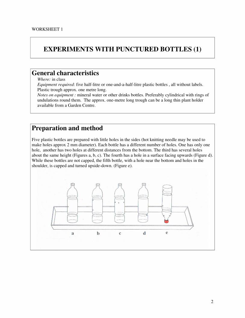
Five plastic bottles are prepared with little holes in the sides (hot knitting needle may be used to
make holes approx 2 mm diameter). Each bottle has a different number of holes. One has only one
hole, another has two holes at different distances from the bottom. The third has several holes
about the same height (Figures a, b, c). The fourth has a hole in a surface facing upwards (Figure d).
While these bottles are not capped, the fifth bottle, with a hole near the bottom and holes in the
shoulder, is capped and turned upside-down. (Figure e).

3
Suggestions for introducing and running the experiments
Fill four of the prepared bottles with water (after temporarily blocking the holes with toothpicks).
Leave them unstoppered. Put them on a platform in the trough to catch the water gushing out. Cap
the remaining bottle.
It is advisable to warn the pupils to watch one bottle at a time and then all of them together.
The quantity of water to be seen spouting out should lead pupils to understand that water spurts out
at right angles to the surface of the containers. It can be noted that water sprays out radially and
horizontally from holes in the vertical sides of the bottles. Even when the holes are not in vertical
sides [for instance in the ruts around the bottles (Figure d) or the curved shoulder (Figure e)], the jet
starts at right angles to the surface
Suggestions for discussion with pupils
Pupils must be made to realise clearly that in the bottle with two holes at different heights sprays are
different. The water spurts out with greater velocity from the lower hole the further it is from the
upper one.

4
WORKSHEET 2
EXPERIMENTS WITH PUNCTURED BOTTLES (2)
General characteristics Where: in class
Equipment required: half-litre or one-and-a-half-litre plastic bottles , all without labels.
Notes on equipment : mineral water or other drinks bottles. Preferably cylindrical with rings of
undulations round them.
Preparation and method
The bottles prepared for the previous activity are used after capping them.
Bottle (e), may also be used, the right way up.
Capping the bottles gives notably different results according to the number of holes and the level of
the water at the moment the bottle is closed.
Suggestions for introducing and running the experiments
You can begin with the bottle with one single hole. The water stops spurting out almost
immediately after capping. The same happens if there are several holes all on the same level.
With several holes at different levels, the result is strange and can be surprising and intriguing. For
instance, for the bottle with two holes (both below water level) , one above the other, it may be
observed that, before capping, water sprays from the two holes (the bottom one with more velocity).
When the cap is put on, the upper water jet stops completely, being replaced by bubbles when air
intermittently enters the bottle. The water flows out of the lower hole at variable speed (one could
say “in fits and starts”), its maximum volume flux being achieved when an air bubble enters
through the upper hole. This continues until the water level sinks below the upper hole. At this point
a continuous flow is established, as if the bottle were not capped.

5
Suggestions for discussion with pupils
Discussion can be in two phases:
a) analysis of how the water behaves in the bottle with one single hole;
b) analysis of how the water behaves in the other bottles.
In the case of a), the jet gradually decreases, because when the water spouts out and its level sinks,
the pressure of the air above it drops below atmospheric pressure. The spray stops when the
atmospheric pressure at the hole is equal to the pressure of the air trapped inside the bottle plus the
hydrostatic pressure (due to imbalance between the free surface of the liquid and the hole).
This explanation cannot be given to the pupils at this point but should be put off (possibly
reproducing the experiment) until they have studied Stevino’s Law.
For the moment, discussion may be held to get the pupils to specify what they think about the air
trapped in the bottle.
In the case of b), the observed behaviour is controlled by weight, by the constancy of volume of the
liquid, and by surface tension (which governs the input of air at the holes and the formation of
bubbles).
It suffices, at this point, if reference to the action of weight comes up in the discussion.
Suggestions for further possible action It is interesting to repeat the experiment with the two-hole bottle, after increasing the size of the
lower hole. It may be observed that the bubbles entering from the upper hole increase in frequency,
whilst the water jet becomes more regular.

6
WORKSHEET 3
EXPERIMENT WITH SQUEEZED BOTTLES
General characteristics Where: in class
Equipment required: half-litre or one-and-a-half-litre plastic bottles , all without labels.
Notes on equipment : mineral water or other drinks bottles. Preferably cylindrical with rings of
undulations round them.
Preparation and method
The bottles from the previous activity can be squashed by hand, thanks to their flexibility.
Put the cap on a bottle containing water, holding the bottle or resting it without squeezing the sides.
The water soon stops spurting out (or it spurts intermittently as in activity 2 if the chosen bottle has
two holes one above the other.
Suggestions for introducing and running the experiment
The sides of the bottle are squeezed by hand. The water jets out immediately, whatever the
configuration of the holes.
Suggestions for discussion with pupils
Series of tests can be repeated by teachers and pupils in different situations, with vertical bottles and
variously inclined ones, with holes made ad hoc at certain points in the plastic, squeezing the bottles
hard or less so (Figure). These should enable pupils to see that squashing makes water spurt out
more forcefully than when the bottle is not squeezed. They can also see that the speed the water
comes out of the various holes differs imperceptibly. These differences are evident only in the
spontaneous flow of water from the holes in open bottles.

7
In addition, if the squeezing is not modified, the position of the bottle (e.g. horizontal, diagonal, or
vertical) makes no difference to the speed of the water jet.
How to analyse the results obtained
It is useful to open a discussion on how the water jets behave, concentrating on what might be
helpfully termed “the state of compression” of the water at the point where the bottle is holed and
the water spurts out. The jet is thus used as an indicator of compression.
Two methods of creating a “state of compression” in the water can be identified:
- a “natural” or “spontaneous” method, operating in the open bottle, where the compression of the
water, as shown by it spurting out, is clearly influenced by how far the hole is below the surface of
the water.
- the other, caused by squeezing, can to some extent be considered “artificial”, since there is
intentional manipulation of the container walls. This action seems to show compression is equal at
all water jet holes, whatever the position of the holes and the bottle. What is more, this second
method can only function when the bottle is capped. (The water spurts practically do not change if
an open bottle is squeezed.)
8
WORKSHEET 4
COMPRESSIBILITY OF WATER AND AIR.
General characteristics Where: in class
Equipment required: a plastic bottle with one hole, and one without hole
Notes on equipment: mineral water or other drinks bottles. Preferably cylindrical with rings of
undulations round them
Preparation and method
It is advisable first to use the bottle without holes and then the holed one.
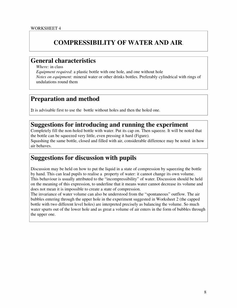
Suggestions for introducing and running the experiment Completely fill the non-holed bottle with water. Put its cap on. Then squeeze. It will be noted that
the bottle can be squeezed very little, even pressing it hard (Figure).
Squashing the same bottle, closed and filled with air, considerable difference may be noted in how
air behaves.
Suggestions for discussion with pupils
Discussion may be held on how to put the liquid in a state of compression by squeezing the bottle
by hand. This can lead pupils to realise a property of water: it cannot change its own volume.
This behaviour is usually attributed to the “incompressibility” of water. Discussion should be held
on the meaning of this expression, to underline that it means water cannot decrease its volume and
does not mean it is impossible to create a state of compression.
The invariance of water volume can also be understood from the “spontaneous” outflow. The air
bubbles entering through the upper hole in the experiment suggested in Worksheet 2 (the capped
bottle with two different level holes) are interpreted precisely as balancing the volume. So much
water spurts out of the lower hole and as great a volume of air enters in the form of bubbles through
the upper one.

9
Suggestions for further possible action This short enquiry into the different compressibility of air and water can be further experimented
with, using bottles partly filled with water. The degree to which they may be squashed is interpreted
as a consequence of how possible it is to reduce only the volume of air in the bottle.
Finally it may be noted that, if holes are made below water level in a bottle containing very little
liquid, capping and squeezing the bottle, the water spurts out at practically the same speed as when
squashing bottles containing very little air (Figure).
How to analyse the results obtained The behaviour just observed suggests the presence of a “chain” of actions: squeezing the walls by
hand….the air is compressed….the water is compressed.…so the water spurts out. Therefore the
state of compression is transmitted from the air to the water.

10
WORKSHEET 5
EXPERIMENTS WITH SYRINGES
General characteristics Where: in class
Equipment required: two or three plastic syringes, 5 or 10 cm3.
Notes on equipment: plastic syringes may be bought at the chemist’s or in health equipment
shops. The needles must be removed before using the syringes.
Preparation and method The enquiry into the behaviour of water observed in the previous worksheets is now extended using
syringes. In one, some little holes are made near the point of the syringe. The 0.5mm diameter holes
can be made with a hot needle.

11
Suggestions for introducing and running the experiments Analysis of the parallelism between plastic bottles and syringes, as far as the behaviour of water is
concerned when put into a “state of compression”, can be developed by performing experiments
using a syringe with little holes near the point. In this case, too, when the plunger is pressed, the
water spurts out at right-angles to the holed surface and the speed obviously depends on how hard
the plunger is pressed (Figure a).
After that, outflow from the vertical syringe without piston is experimented with (Figure b).
Suggestions for discussion with pupils Analogies between bottles and syringes can be discussed to underline that a deformation of the
bottle sides is obtained, in the syringe, by moving the plunger.
Preliminary tests with non-holed syringes easily demonstrate the importance of ensuring that the
syringe remains tightly closed. Closing the syringe with a finger or something soft, like a rubber,
roughly proves how difficult it is to stop leaks of water or air when the plunger is pressed or air
bubbles coming in when it is pulled. The solution, giving a secure closure, is to melt the plastic at
the outlet with a lighter or match. How good the seal is can be checked by holding the syringe under
water and compressing the air. If no bubbles come out, the seal is tight. This is also the way to
check how much compression the plunger will take; the air can be compressed until bubbles come
out round the plunger.
To collect a desired quantity of water in the sealed syringe, a method may be employed taking
advantage of the relative flexibility of the plastic of the syringe. A syringe in the vertical position is
completely filled with water. Before putting in the plunger, a thin copper wire (for electric winding)
is inserted in the cylinder (Figure a). When the plunger is put in and pushed down, this wire remains
caught between the piston’s washer and the wall of the cylinder. The thickness of the wire thus
gives a path for liquid to exit (Figure b). When the plunger reaches a position corresponding to the
desired quantity of water, the wire is pulled out and the plunger stays put (Figure c). This re-
establishes the plunger’s seal and the experiment of pushing or pulling can begin.
The same can be done with air .

12
Suggestions for further possible action Using a syringe facilitates experimental enquiry into the compressibility of air and the
incompressibility of water. The plunger of a syringe can be pulled as well as pushed and can
therefore also increase the volume of fluid contained (if the fluid is air).
A few tests suffice to discover the incompressibility of water. For air, however, it is easy to note
that its volume can be reduced but also increased. What is more, it will be noted that air tends to
return to its starting volume (plunger at rest) as soon as pushing or pulling ceases. This behaviour of
air can be compared to that of a spring. The condition of the gas corresponding to the “at rest”
plunger position can be termed a condition of “balance”. Indeed it is in balance with the
atmosphere.
.
.

13
WORKSHEET 6
AIR BUBBLE IN WATER-FILLED SYRINGE
General characteristics Where: in class
Equipment required: sealed (by melting the outlet) plastic syringes ; open vials of such size as to
fit into the syringes
Notes on equipment: vials for distilled water or other chemicals may be used. They are
removable if they can be washed in water.
Preparation and method Several syringes are prepared by heating the point sufficiently to seal it.
The vials are emptied of their contents and partly filled with water, leaving an air bubble trapped in
each (Figure 1)
The vials thus prepared allow information to be gathered directly on what is happening to the water
in each syringe when it is pressed by the plunger.

14
Suggestions for introducing and running the experiment
Each vial with an air bubble inside is introduced into a syringe already filled with water, the vial
opening towards its point (Figure 2)
The plunger is partly inserted into the syringe, using the method given in Worksheet 5.
When the plunger is pressed (see figure), contraction is noticed in the air bubble trapped in the vial.
The more the pressure, the greater the contraction.
The tests can be carried out by pupils (possibly divided into groups) each with a syringe, an open
empty vial, a tray and some water.
Suggestions for discussion with pupils
Pupils should be asked questions like “when I press the plunger, why does water enter the vial?”.
This should start discussion about what they observe, their descriptions and explanations they give.
It is important for pupils to realise that the contraction in the air bubble is due to forces acting on the
surface separating water and air bubble (“the water compressed by the plunger presses on the air
bubble”).
Another thing to be underlined is that the force acting on the surface of the air bubble is opposite to
that applied to the plunger.
The situation may be summarised as follows:
a) Water can enter the vial because the air, compressed by the water, reduces in volume.
b) The direction of force is inverted
Pupils can realise that this “behaviour” of water fits with all the results observed in the preceding
activities, regarding the direction of water jets. It shows that water acts with forces at right angles to
the container walls or to the surface of the air bubble.

15
How to analyse the results obtained
Discussion should be launched leading the class to formulate how water behaves, such as the
following:
“ Whatever direction has the force producing the compression of the water, the water exerts forces
perpendicular to the walls of the container”.
Discussion should also lead to recognising that this is due to water being a fluid and, as such, being
able to adapt its shape to suit the form of whatever recipient it is contained and compressed in.
It may also be useful to compare this result with the behaviour observed in solids when they are
pressed. Solid bodies (because they are rigid, i.e. capable of maintaining their shape) exert forces
dependent on the direction of the force applied to them.

16
WORKSHEET 7
CONNECTED SYRINGES
General characteristics Where: in class
Equipment required: plastic syringes of different sizes, from 5 cm3 to 10 cm3, in equal numbers.
Flexible thin tubes with which to connect the injection end of the syringes (phleboclysis tubes do
very well). Some small rubber balloons.
Notes on equipment: the chemist’s or health equipment shops that sell syringes also supply the
tubing. Rubber balloons can be found in toy shops.
Preparation and method Connect two syringes with tubing 40-50 cm long.
Tubes should be prepared both with two equal size syringes and with two different diameter ones.
Suggestions for introducing and running the experiments The experiment phase with syringes can be concluded by observing a set-up of two syringes
interconnected by flexible tubing. Having filled syringes and tubing with water, the teacher first
verifies with the pupils that if one of the plungers is pushed in the other comes out a certain
distance. The experiment is conducted both with and equal sized pair of syringes and with two
syringes of different diameters (Figure 1). This once again confirms the invariability of water
volume.
Suggestions for discussion with pupils The displacements of the two plungers in syringes of equal diameter should be measured. Within
precision measuring limits, the displacements can be recognised as equal. It may therefore be
concluded that “as much water is expelled from one syringe as is transferred to the other syringe.
The volume of water does not change.”

17
Discussion may be more difficult to recognise that this result can also be obtained by measuring the
behaviour of different sized syringes. Many difficulties arise from the pupils’ lack of confidence in
calculating the volume of water transferred starting from the displacements of the plungers and
from the diameter of the syringes. (Basically, many pupils may have difficulty in recognising that
the formal aspect of the problem lies in calculating the volume of two different-section and different
height cylinders and checking that it is the same.)
How to analyse the results obtained
It is not easy to evaluate the forces at play on the syringes and their interrelationship because of the
friction between the walls and plungers of plastic syringes. So, the measurements that can be made
in class could provide results which are difficult to interpret.
Regarding the forces exerted by the water within the set-up, the teacher can show that, pressing on
one plunger not only transmits force to the other but that forces are applied to all surfaces within the
set-up, including the walls of the connecting tube. This fact can be demonstrated by replacing the
single tube by a double one joined by a thin expandable rubber tube from a balloon (Figure 2a)
If one presses the plunger of one syringe and blocks the plunger of the other syringe from
coming out, the section of balloon is seen to expand very obviously (Figure 2b). This clearly
indicates how force is also applied on the connecting tube, i.e. radially and not only longitudinally.
This result confirms the interpretation that force is at right angles to the retaining walls, as can
already be deduced from analysing the way water spurts out from the bottles and the syringes.


