The Parapodium: An Orthotic Device for Neuromuscular Disorders
12
Artificial Limbs, Vol. 15, No. 2, pp. 36-47, Autumn 1971 The Parapodium: An Orthotic Device for Neuromuscular Disorders WALLACE MOTLOCH, CO. 1 Some of the serious shortcomings of the standard brace for young patients with paralysis of the lower extremities are the lack of adjustability to accommodate growth and contractures, excessive weight, in¬ stability, difficulty in locking and unlocking, and the time required for donning and re¬ moval. The Parapodium (3) was designed in the effort to introduce a modular system that offers alternatives and resolves some of those difficulties. The Parapodium facilitates standing without crutches, thus freeing the patient's hands for a wider range of activities. The difference between tripod standing and crutchless standing is a major distinction between our approach to brace design and that of conventional braces. This orthosis is best suited for patients with severe spina bifida or traumatic para¬ plegia; however, it also may be prescribed for other neuromuscular disorders in which stability of the brace (permitting standing or swivelling without crutches), lightness of the device, and an upright position are important. Because of the modular design, growth in a child is easily accommodated. The foot¬ plate will accept several sizes of regular boots; there are four sizes of footplates for boots from 5 1/2 in. to 9 1/2 in. long. The height of the Parapodium can be adjusted by replacing the tubular sidebars with a longer piece of tubing, which is cut from 1 Orthotic Research and Development Spina Bifida Unit, Ontario Crippled Children's Centre, Toronto, Canada. This article was extracted from the report "Parapodium" prepared in collaboration with Sunnybrook Hospital, Toronto, February 1971. 36 standard 1/2-in. or 5/8-in. aluminum tub¬ ing, and the back panel is made in two pieces to provide for width adjustment. The Parapodium is constructed of light¬ weight, high-strength aluminum (2024T6) throughout. The average weight is between 8% and 14% of the body weight. The weight of a standard brace may be as much as 15% to 22%. For stability, the footplate, sidebars, and back panel form a continuous rigid loop, cross-braced by a bar at the level of the knee. The shape of the bar virtually elimi¬ nates side-to-side movement, thus im¬ proving the anterior-posterior and medial-lateral stability of the unit. The knee pads are shaped from 2-in. Ethafoam (TM) blocks. If contractures occur, they can be accommodated by deepening the knee cutouts in the foam block. One of the unique features of this orthosis is the means used to lock and unlock the hip and knee joints. A set of folding handles is used to rotate the upright bars and thus rotate the hip and knee joints. For standing, the joint axes are aligned in the A-P direc¬ tion; when rotated 90 degrees to the M-L position, the joints are free to flex. Also, it should be noted that one of the more dif¬ ficult tasks a paraplegic has is to, extend his extremities fully so that he can lock his braces; the rotating sidebars not only lock the brace, but also extend it the last few degrees. Since the patient's shoes are not perma¬ nently attached to the brace, he is able to put on and remove the brace without wast¬ ing time lacing and unlacing the boot. Also, the boot remains on the patient's foot to
Transcript of The Parapodium: An Orthotic Device for Neuromuscular Disorders
Artificial Limbs, Vol . 15, No. 2, pp. 3 6 - 4 7 , Autumn 1971
The Parapodium: An Orthotic Device for Neuromuscular Disorders
W A L L A C E M O T L O C H , C O . 1
Some of the serious shortcomings of the standard brace for young patients with paralysis of the lower extremities are the lack of adjustability to accommodate growth and contractures, excessive weight, in¬ stability, difficulty in locking and unlocking, and the t ime required for donning and re¬ moval. The Parapodium (3) was designed in the effort to introduce a modular system that offers alternatives and resolves some of those difficulties.
The Parapodium facilitates standing without crutches, thus freeing the patient 's hands for a wider range of activities. The difference between tripod standing and crutchless standing is a major distinction between our approach to brace design and that of conventional braces.
This orthosis is best suited for patients with severe spina bifida or t raumatic para¬ plegia; however, it also may be prescribed for other neuromuscular disorders in which stability of the brace (permitting standing or swivelling without crutches), lightness of the device, and an upright position are important .
Because of the modular design, growth in a child is easily accommodated. The foot¬ plate will accept several sizes of regular boots; there are four sizes of footplates for boots from 5 1/2 in. to 9 1/2 in. long. The height of the Parapodium can be adjusted by replacing the tubular sidebars with a longer piece of tubing, which is cut from
1 Orthotic Research and Development Spina
Bifida Unit, Ontario Crippled Children's Centre,
Toronto, Canada. This article was extracted from the
report " P a r a p o d i u m " prepared in collaboration with
Sunnybrook Hospital , Toronto, February 1971.
36
standard 1/2-in. or 5/8-in. aluminum tub¬ ing, and the back panel is made in two pieces to provide for width adjustment.
The Parapodium is constructed of light¬ weight, high-strength aluminum (2024T6) throughout. The average weight is between 8% and 14% of the body weight. The weight of a standard brace may be as much as 15% to 22%.
For stability, the footplate, sidebars, and back panel form a continuous rigid loop, cross-braced by a bar at the level of the knee. The shape of the bar virtually elimi¬ nates side-to-side movement, thus im¬ proving the anterior-posterior and medial-lateral stability of the unit .
The knee pads are shaped from 2-in. Ethafoam (TM) blocks. If contractures occur, they can be accommodated by deepening the knee cutouts in the foam block.
One of the unique features of this orthosis is the means used to lock and unlock the hip and knee joints . A set of folding handles is used to rotate the upright bars and thus rotate the hip and knee joints . For standing, the joint axes are aligned in the A-P direc¬ tion; when rotated 90 degrees to the M-L position, the joints are free to flex. Also, it should be noted that one of the more dif¬ ficult tasks a paraplegic has is to, extend his extremities fully so that he can lock his braces; the rotating sidebars not only lock the brace, but also extend it the last few degrees.
Since the patient 's shoes are not perma¬ nently attached to the brace, he is able to put on and remove the brace without wast¬ ing time lacing and unlacing the boot. Also, the boot remains on the patient 's foot to

Fig. 1.

38 M O T L O C H
protect it from scratches and bruises. In addition, the t ime for donning and remov¬ ing the brace has been greatly reduced because of the simplicity of the locking method. Our older patients can remove this brace in 15 to 20 seconds, whereas it could take from 5 to 20 minutes to remove a stan¬ dard brace. Donning the Parapodium takes 45 to 90 seconds; donning a standard brace takes 10 to 20 minutes.
A minumum of maintenance is required. Because of the use of aluminum, the parts do not need to be plated to prevent corro¬ sion, there are no delays for plating, and nylon does not need lubrication. No screws are used in the sidebars, nor leather for straps.
Because of the modular kit, the device can be assembled speedily. If no special modifications of the kit are needed, the fitting can be completed in two hours. Also, repairs or growth adjustments can be made while the patient waits.
Simple, clean lines, with no buckles, straps, or corsets, have superseded the cluttered look of the standard braces. The aluminum is easily cleaned or buffed, and it may be anodized when the brace is finished.
The Parapodium is easily aligned. An alignment block at the bottom of each up¬ right enables the orthotist to align the brace while it is being worn. The brace can be aligned for maximum comfort while stand¬ ing or for maximum stability.
CLINICAL CONSIDERATIONS
When the child indicates the desire to stand up by pulling up on furniture and other objects, or when he has developed sufficiently to stand, a bracing program may commence. (For a presentation on the orthotics aspects of treating children with spina bifida, the reader is referred to "Therapy Treatment Suggestions" by Elizabeth L. Hamilton, P.T., in 3.)
In some cases, a prebracing device, the "caster car t" (2,3), or a preliminary brace, the "standing brace" (2,3), may be used. At this center, the criteria for considering the use of the Parapodium are:
1. The patient does not have sufficient
muscle power in his lower extremities and trunk to ambulate and stand without crutches.
2. The patient has either gone through the standing-brace stage or is physically and mentally ready to go directly into the Parapodium.
3. The patient is of such size that com¬ fortable sitting can only be accomplished by flexing the knees and hips.
In addition, the following points should be checked before a Parapodium is considered:
1. Upper-extremity coordination and strength. Can this person use crutches or walkers effectively for ambulation? If only standing is required, this point might not be important.
2. Condition of the feet. Can shoes be worn? Can the skin, bones, and joints with¬ stand weight-bearing? Custom shoes, special padding, and plantar-flexion wedges could be used. A physiotherapy program can prepare the patient for weight-bearing.
3. Deformities and contractures. Check the legs, pelvis, and spine for severe de¬ formities. Orthopedic surgery and physiotherapy can be of great value. Minor deformities can be accommodated without special modifications.
4. Skin condition. Check for sores and for hypersensitive areas over the chest (front panel area), sacrum (buttocks sup¬ port), and patellar tendon and knees (knee pads).
5. Protruding myelomeningocele and spinal deformities. Can a body jacket sup¬ port the trunk? Is there enough clear area
Fig. 2. The semiassembled Parapodium kit as it is supplied by the manufacturer.

T H E P A R A P O D I U M 39
over the sacrum for a good buttocks-sup¬ port panel?
ASSEMBLY AND FITTING
The parts of the Parapodium and the "kit" supplied by the manufacturer are shown in figures 1 and 2.
The tools required to assemble the kit are: a tape measure, knife, hacksaw, file, portable drill with 1/8-in. drill bit, pop-riveter, and a 1/2-in. reamer.
Step 1. Obtain a pair of lace-to-toe boots. Check their fit on the patient carefully; it is better that they tend to be loose rather than tight. Fig. 4.
Fig. 3. Fig. 5.
Fig. 6.
Step 2 (fig. 3). Fit the shoes into the foot¬ plate. Make sure that the clamps (toe and heel) hook securely over the welt of the shoe and that the spring is taut enough to hold the shoes in place. Sometimes it may be necessary to change the height of the heel-clamp block, toe-clamp post, and the curvature cutouts of the heel and toe clamps.
Figure 4 illustrates the position of the knee pad. Note that the patellar tendon is used in this case and that the block has to be shaped to concentrate pressure on the patellar tendon.
Step 3 (fig. 5). With the shoes on the pa¬ tient, clamp the lower part of the brace in place. Hold the knees in the desired posi¬ tion (anteroposterior and mediolateral) and mark the cutout for the knee on the foam block.
Step 4 (fig. 6). With the marked knee pad over the patellar tendon, mark the length of the tube shin section.

40 M O T L O C H
Fig. 7. Fig. 10.
Fig. 8.
Fig. 9. Fig. 11. Fit t ing of the back panel.
Step 5 (fig. 7). The knee cutouts are shaped as marked.
Step 6 (fig. 8). Check the fit of the knee cutouts. At this time, only a rough fit is necessary; a final check and smoothing is done later.
Step 7 (fig. 9). Cut off the tube shin sec¬ tions as marked in step 4. File the end flat and clean out the burr from the inside of the tube.
Step 8 (fig. 10). Clamp the lower section in place and check the fit of the knee cut¬ outs to ensure patellar-tendon pressure-bearing, and also check the length of the shin sections.
BACK PANEL
The back panel is effective only in cases of good spine stability, minor deformities, and meningocele protuberance higher than the sacral area. For fitting of more severe cases, see the "Spinal Deformities" section.
The panel should be fitted rather loosely because the width across the greater tro-chanters increases with weight-bearing (fig. 11).
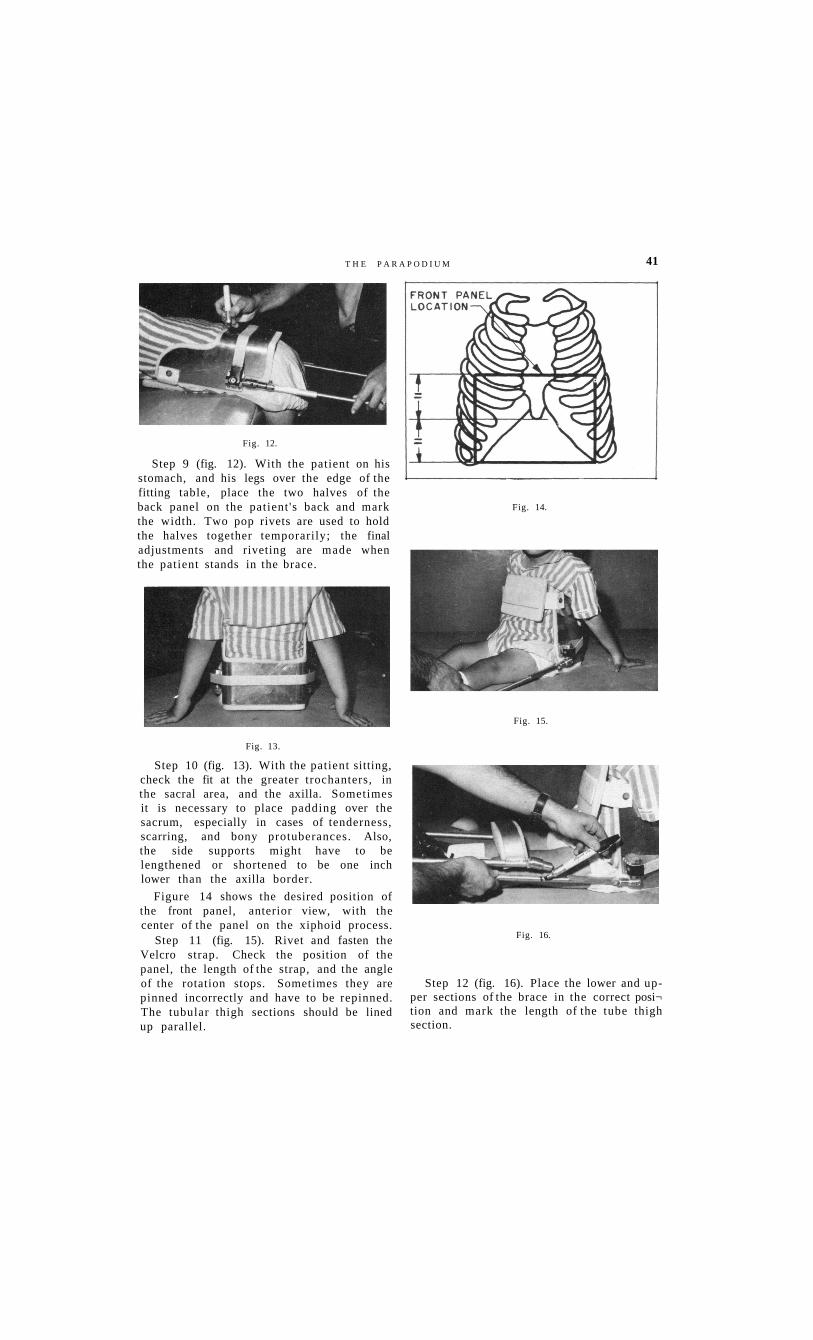
Fig. 12.
Step 9 (fig. 12). With the patient on his stomach, and his legs over the edge of the fitting table, place the two halves of the back panel on the patient 's back and mark the width. Two pop rivets are used to hold the halves together temporarily; the final adjustments and riveting are made when the patient stands in the brace.
Fig. 13.
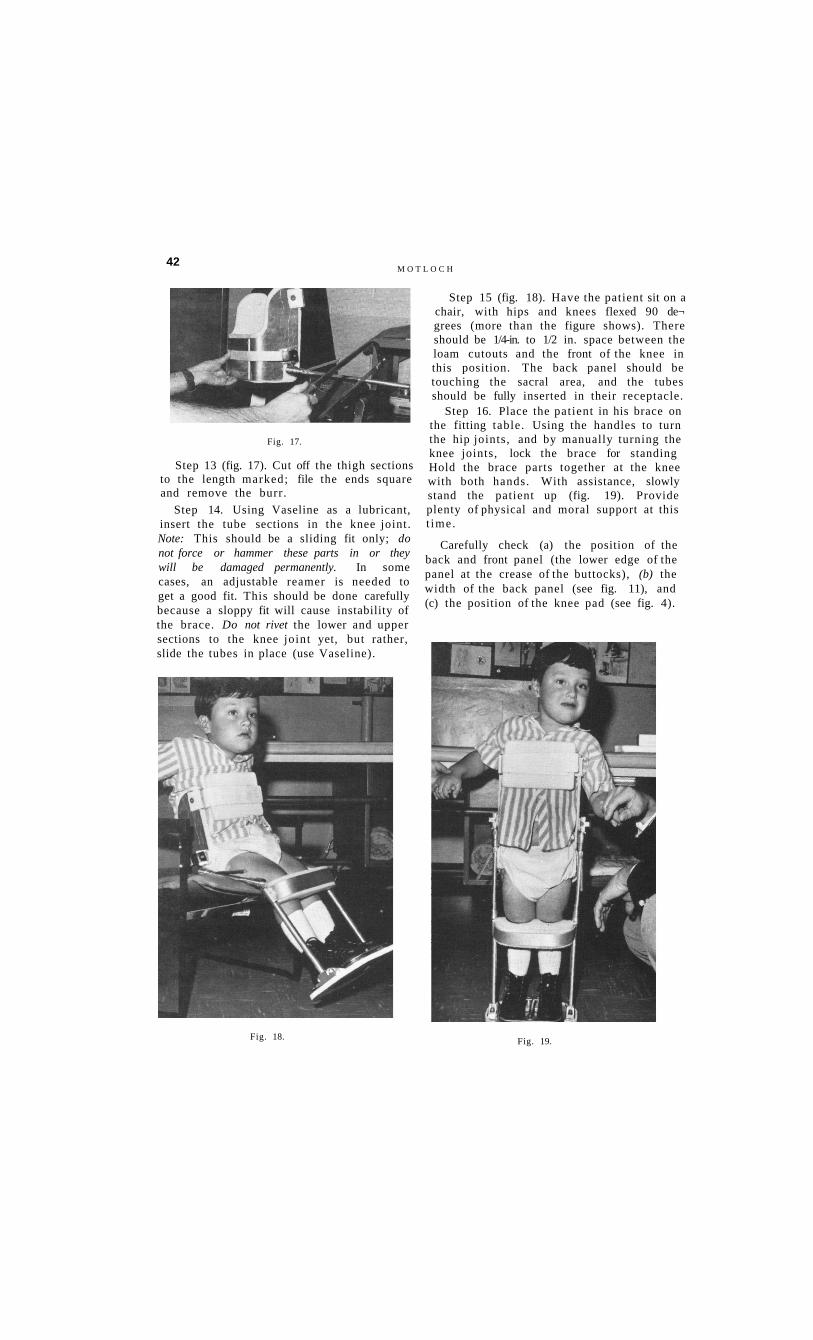
Step 10 (fig. 13). With the patient sitting, check the fit at the greater trochanters, in the sacral area, and the axilla. Sometimes it is necessary to place padding over the sacrum, especially in cases of tenderness, scarring, and bony protuberances. Also, the side supports might have to be lengthened or shortened to be one inch lower than the axilla border.
Figure 14 shows the desired position of the front panel, anterior view, with the center of the panel on the xiphoid process.
Step 11 (fig. 15). Rivet and fasten the Velcro strap. Check the position of the panel, the length of the strap, and the angle of the rotation stops. Sometimes they are pinned incorrectly and have to be repinned. The tubular thigh sections should be lined up parallel.
Fig. 15.
Fig. 16.
Step 12 (fig. 16). Place the lower and upper sections of the brace in the correct posi¬ tion and mark the length of the tube thigh section.
Fig. 14.
T H E P A R A P O D I U M 41
42 M O T L O C H
Fig. 17.
Step 13 (fig. 17). Cut off the thigh sections to the length marked; file the ends square and remove the burr.
Step 14. Using Vaseline as a lubricant, insert the tube sections in the knee joint. Note: This should be a sliding fit only; do not force or hammer these parts in or they will be damaged permanently. In some cases, an adjustable reamer is needed to get a good fit. This should be done carefully because a sloppy fit will cause instability of the brace. Do not rivet the lower and upper sections to the knee joint yet, but rather, slide the tubes in place (use Vaseline).
Fig. 18. Fig. 19.
Step 15 (fig. 18). Have the patient sit on a chair, with hips and knees flexed 90 de¬ grees (more than the figure shows). There should be 1/4-in. to 1/2 in. space between the loam cutouts and the front of the knee in this position. The back panel should be touching the sacral area, and the tubes should be fully inserted in their receptacle.
Step 16. Place the patient in his brace on the fitting table. Using the handles to turn the hip joints, and by manually turning the knee joints, lock the brace for standing Hold the brace parts together at the knee with both hands. With assistance, slowly stand the patient up (fig. 19). Provide plenty of physical and moral support at this t ime.
Carefully check (a) the position of the back and front panel (the lower edge of the panel at the crease of the buttocks), (b) the width of the back panel (see fig. 11), and (c) the position of the knee pad (see fig. 4).

T H E P A R A P O D I U M 43
It is important to ensure that the panel does not rise up significantly in standing as compared to sitting. If that occurs, first check the operation in step 12; if that is sat¬ isfactory, then the mounting plates have to be raised the distance of the rise, usually 1 in. to 2 in. Also, be sure that the side of the back panel does not interfere with func¬ tion of the upper extremity.
After the Parapodium has been fitted, it is assembled permanently and the knee cutouts are smoothed.
(a) The knee bar sleeve is lubricated with Vaseline, and the nylon washer is inserted under it. This washer is needed because it prevents the brace from squeaking.
(b) Insert the knee joints, with the bar and washer, into the shin-tube section, drill a 1/8-in. hole for a pop rivet about 1/2 in. from
the top of the tube, and pop-rivet together.
(c) Insert the thigh sections (upper part of the brace) into the knee joints and fold the brace into a sitting position; drill a 1/8-in. hole and pop-rivet the thigh section in place.
(d) Stretch the elastic back strap and fasten with a pop rivet.
(e) Straighten and fold the brace a few times to check for stiffness and joint misalignment.
Step 17 (fig. 20). Put the brace on the patient and check the alignment. Optimal alignment is achieved when the patient (without crutches, hands on sides) can al¬ most balance on a quarter-inch dowel. The footplate is divided into three equal parts, and the dowel is placed at the junction of the front one-third and the back two-thirds.
If adjustment in alignment is needed (fig. 21), it is accomplished by tightening one alignment-block nut and loosening the other. The alignment blocks can be rotated, and inclining the brace with a patient in it should always be done to the cutaway side of the block.
Step 18. Crutchless standing in the assem¬ bled brace is now possible, but should not be forced on the patient; it will come with t ime. From now on, wearing tolerance should be built up gradually and activities increased.
Fig. 20. Fig. 2 1 .

44 M O T L O C H
ORTHOTIC CHECK-OUT
A form such as is shown in figure 22 can be used for the orthotic check-out.
Fig. 22. A form suitable for recording orthotic-
evaluation information.
Fig. 23.
Figure 23 shows a tipping platform that is used for objectively measuring and com¬ paring the stability of lower-extremity or-thotics while they are being worn.
A pressure-sensing device, if used rou¬ tinely, significantly reduces trouble spots by detecting excessive pressure before it causes breakdown of the desensitized skin.
The Parapodium is aligned properly if the patient can tolerate the same number of degrees to the left as to the right, and about one-third forward as compared to two-thirds backward. In this way, the brace is equally stable towards either side, but it is about 30% easier to fall forward than backward, thus facilitating swing-through gait with the use of crutches.
ADAPTATIONS
LEG-LENGTH DISCREPANCY
Sometimes it is necessary to build up the footplate and to change the height of the toe and heel clamp to accommodate leg shortening. A Plastazote (TM) block equal to the shortening is glued to the base plate. The shoe is placed on it, and the clamps are then modified (fig. 24) to hold the shoes in place.
Fig. 24.
SIGNIFICANT PLANTAR FLEXION
There are two ways of dealing with this problem. If possible, wedged Plastazote shoe inserts should be fabricated and glued in as insoles. However, if the plantar flexion is too great for insoles, a combination of in¬ sole wedge and outside wedge can be used. A wedge of Plastazote, with a proper slope, is glued to the base plate, and the heel clamp is raised by lengthening the heel-clamp post.
T H E P A R A P O D I U M 45 KNEE HYPEREXTENSION
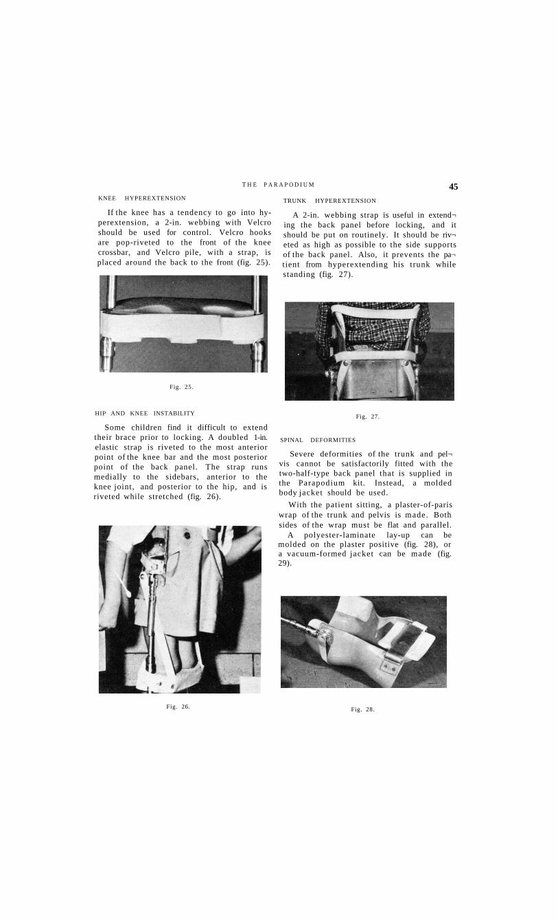
If the knee has a tendency to go into hy-perextension, a 2-in. webbing with Velcro should be used for control. Velcro hooks are pop-riveted to the front of the knee crossbar, and Velcro pile, with a strap, is placed around the back to the front (fig. 25).
TRUNK HYPEREXTENSION
A 2-in. webbing strap is useful in extend¬ ing the back panel before locking, and it should be put on routinely. It should be riv¬ eted as high as possible to the side supports of the back panel. Also, it prevents the pa¬ tient from hyperextending his trunk while standing (fig. 27).
Fig. 25.
Fig. 27. HIP AND KNEE INSTABILITY
Some children find it difficult to extend their brace prior to locking. A doubled 1-in. elastic strap is riveted to the most anterior point of the knee bar and the most posterior point of the back panel. The strap runs medially to the sidebars, anterior to the knee joint, and posterior to the hip, and is riveted while stretched (fig. 26).
Fig. 26.
SPINAL DEFORMITIES
Severe deformities of the trunk and pel¬ vis cannot be satisfactorily fitted with the two-half-type back panel that is supplied in the Parapodium kit. Instead, a molded body jacket should be used.
With the patient sitting, a plaster-of-paris wrap of the trunk and pelvis is made. Both sides of the wrap must be flat and parallel.
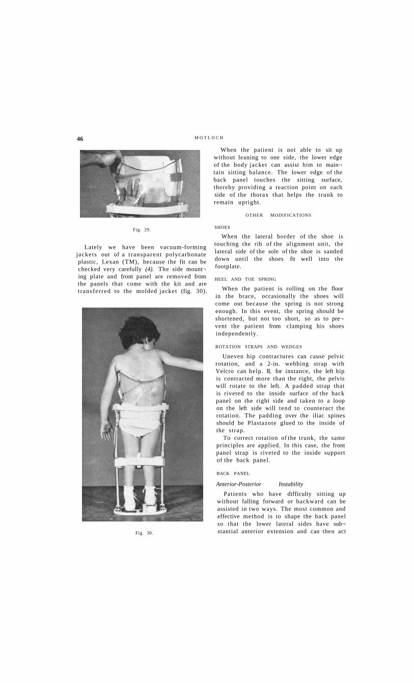
A polyester-laminate lay-up can be molded on the plaster positive (fig. 28), or a vacuum-formed jacket can be made (fig. 29).
Fig. 28.
M O T L O C H 46
Fig. 29.
Lately we have been vacuum-forming jackets out of a t ransparent polycarbonate plastic, Lexan (TM), because the fit can be checked very carefully (4). The side mount¬ ing plate and front panel are removed from the panels that come with the kit and are t ransferred to the molded jacket (fig. 30).
Fig. 30.
When the patient is not able to sit up without leaning to one side, the lower edge of the body jacket can assist him to main¬ tain sitting balance. The lower edge of the back panel touches the sitting surface, thereby providing a reaction point on each side of the thorax that helps the trunk to remain upright.
OTHER MODIFICATIONS
SHOES
When the lateral border of the shoe is touching the rib of the alignment unit, the lateral side of the sole of the shoe is sanded down until the shoes fit well into the footplate.
HEEL AND TOE SPRING
When the patient is rolling on the floor in the brace, occasionally the shoes will come out because the spring is not strong enough. In this event, the spring should be shortened, but not too short, so as to pre¬ vent the patient from clamping his shoes independently.
ROTATION STRAPS AND WEDGES
Uneven hip contractures can cause pelvic rotation, and a 2-in. webbing strap with Velcro can help. If, for instance, the left hip is contracted more than the right, the pelvis will rotate to the left. A padded strap that is riveted to the inside surface of the back panel on the right side and taken to a loop on the left side will tend to counteract the rotation. The padding over the iliac spines should be Plastazote glued to the inside of the strap.
To correct rotation of the trunk, the same principles are applied. In this case, the front panel strap is riveted to the inside support of the back panel.
BACK PANEL
Anterior-Posterior Instability
Patients who have difficulty sitting up without falling forward or backward can be assisted in two ways. The most common and effective method is to shape the back panel so that the lower lateral sides have sub¬ stantial anterior extension and can then act
T H E P A R A P O D I U M 47
as a 90-degree stop for the back panel. The second method is to supply them with 90-degree hip locks.
Protruding Coccyx
A cutout in the back panel, lined with Plastazote, relieves the pressure. In the case of one of our patients, before the cutout was made, a pressure reading of 35 psi was recorded.
FRONT PANEL
Instability of the Upper Thorax
With a high thoracic myelomeningocele, it is often difficult to prevent the head and shoulder from falling forward. A modified front panel with shoulder straps on the brace can help.
Lordosis
An enlarged version of the front panel with an extra set of lower straps might have a beneficial effect, but on the mobile curva¬ ture only.
Ileostomy
The front panel can be modified to ac¬ commodate an ileostomy conduit.
HANDLES
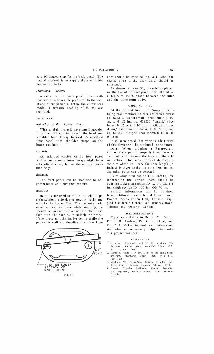
Handles are used to rotate the whole up¬ right section; a 90-degree rotation locks and unlocks the brace. Note: The patient should never unlock the brace while standing; he should lie on the floor or sit in a chair first, then turn the handles to unlock the brace. If the brace unlocks inadvertently while the patient is walking, the direction of the knee
Fig. 3 1 .
axes should be checked (fig. 31). Also, the elastic strap of the back panel should be shortened.
As shown in figure 31 , if a ruler is placed on the flat of the knee joint, there should be a 1/4-in. to 1/2-in. space between the ruler and the other joint body.
ORDERING K I T S
At the present time, the Parapodium is being manufactured in four children's sizes: no. 603319, "super small," shoe length 5 1/2 in. to 6 1/2 in.; no. 603320, "smal l ," shoe length 6 1/2 in. to 7 1/2 in.; no. 603321, "medium," shoe length 7 1/2 in. to 8 1/2 in.; and no. 603338, "large," shoe length 8 1/2 in. to 9 1/2 in.
It is anticipated that various adult sizes of this device will be produced in the future.
N O T E : When ordering a Parapodium kit, obtain a pair of properly fitted lace-to-toe boots and measure the length of the sole in inches. This measurement determines the size of the kit. Once the shoe length (in inches) is given to the ordering department, the other parts can be selected.
Extra aluminum tubing (AL 2024T4) for lengthening the upright bars should be kept in stock: shin section ID V2 in., OD 5/8 in.; thigh section ID .430 in., OD V2 in.
Further information can be obtained from: Orthotic Research and Development Project, Spina Bifida Unit, Ontario Crip¬ pled Children's Centre, 350 Rumsey Road, Toronto 350, Ontario, Canada.
ACKNOWLEDGMENTS
My sincere thanks to Dr. N. C. Carroll, Dr. J. R. Corless, Dr. G. J. Lloyd, and Dr. C. A. McLaurin, and to all patients and staff who so generously helped to make this project possible.
R E F E R E N C E S
1. Hamilton, Elizabeth, and W. M. Motloch, The Toronto standing brace, Inter-Clinic Inform. Bull., 8:7:7-12, April 1969.
2. Motloch, Wallace, A new item for the spina bifida program, Inter-Clinic Inform. Bull., 9:10:10-13, July 1970.
3. Motloch, W., Parapodium, Ontario Crippled Chil¬ dren's Centre, Toronto, Canada, February 1971.
4. Ontario Crippled Children's Centre, Rehabilitation Engineering Research Report 1970, Toronto, Canada .