THE ORIGINAL APPENDICES TO THE ACCIDENT … · THE ORIGINAL APPENDICES TO THE REPORT ON ... NEAR...
157
THIS IS A REFORMATTED VERSION OF THE ORIGINAL APPENDICES TO THE REPORT ON ACCIDENT TO VISCOUNT 803 AIRCRAFT EI-AOM NEAR TUSKAR ROCK, CO. WEXFORD ON 24th MARCH, 1968 APPENDICES TO THE REPORT ON AN INVESTIGATION MADE UNDER REGULATION 7 OF THE AIR NAVIGATION (INVESTIGATION OF ACCIDENTS) REGULATIONS, 1957 (S.I. No. 19 of 1957) The Report into this accident was originally published in 1970. However the Appendices to the Report were not published, but were available for inspection at the offices of the then Department of Transport and Power. Due to continued public interest in this accident, the Appendices to the Report are now republished on the Air Accident Investigation Unit web-site. In order to publish the Appendices on a web-site, it has been necessary to electronically re-format the original documents. The quality of the original text precluded scanning of the original document. The Appendices were therefore re-typed in full. No editorial changes, or corrections to the original text, have been made during this re-typing. The original drawing and graphs were scanned, and only enhanced where the scan of the original document was unsatifactory and illegible. Each page of the orignal Appendices have been reproduced as a separate web page. This format was selected in order to keep as close to the format of the original Appendices. Some of the drawings and the map at the end of Appendix 6 were originally produced in approximately A2 size. To facilitate the reader, this version of the Appendices contains these drawings and the map in two formats. 1. In the first format is the drawing or map reduced to a single A4 size, so that the complete page can be viewed. This, however, results in some loss of detail. 2. The second format consists of the drawing or map split into three pages, each to original size, which can be used to produce a full size mosaic of the origina
Transcript of THE ORIGINAL APPENDICES TO THE ACCIDENT … · THE ORIGINAL APPENDICES TO THE REPORT ON ... NEAR...
THIS IS A REFORMATTED VERSION OF
THE ORIGINAL APPENDICES TO THE
REPORT ON
ACCIDENT TO
VISCOUNT 803 AIRCRAFT EI-AOM
NEAR TUSKAR ROCK, CO. WEXFORD
ON 24th MARCH, 1968
APPENDICES TO THE REPORT ON AN INVESTIGATION
MADE UNDER REGULATION 7 OF THE
AIR NAVIGATION (INVESTIGATION OF ACCIDENTS)
REGULATIONS, 1957 (S.I. No. 19 of 1957)
The Report into this accident was originally published in 1970. However the Appendices to the Report were
not published, but were available for inspection at the offices of the then Department of Transport and
Power. Due to continued public interest in this accident, the Appendices to the Report are now republished
on the Air Accident Investigation Unit web-site.
In order to publish the Appendices on a web-site, it has been necessary to electronically re-format the
original documents. The quality of the original text precluded scanning of the original document. The
Appendices were therefore re-typed in full. No editorial changes, or corrections to the original text, have
been made during this re-typing. The original drawing and graphs were scanned, and only enhanced where
the scan of the original document was unsatifactory and illegible.
Each page of the orignal Appendices have been reproduced as a separate web page. This format was selected
in order to keep as close to the format of the original Appendices.
Some of the drawings and the map at the end of Appendix 6 were originally produced in approximately A2
size. To facilitate the reader, this version of the Appendices contains these drawings and the map in two
formats.
1. In the first format is the drawing or map reduced to a single A4 size, so that the complete page can be
viewed. This, however, results in some loss of detail.
2. The second format consists of the drawing or map split into three pages, each to original size, which
can be used to produce a full size mosaic of the origina

Appendices (Main Menu)
1. Report on search and salvage – "Operation Tuskar".
2. Transcripts of tape recordings of R/T exchanges between EI-AOM and Air Traffic Services (Air
Traffic Control Services).
3. Meteorological data.
4. Investigation of recovered wreckage –
• airframe;
• engines and propellers.
Investigation of auto-pilot.
Summary of witnesses’ statements – map of witnesses’ locations.
Photographs.

Appendix 1
"OPERATION TUSKAR"
SEQUENCE OF EVENTS
24th
March 1968 Viscount EI-AOM. Missing on flight Cork to London about noon. Last reported
position "By Bannow". Search and Rescue operations commenced about 1230 under
coordination of R.N. Brawdy. Search directed more towards Welsh coast.
Involved on Irish Coast side – Aer Lingus, Air Corps, Private Planes. RNLI
Lifeboats, Local Fishing Vessels
25th
March "Macha" at Killybegs, alerted 250020.
"Macha" sailed from Killybegs 0232.
First bodies recovered N.E. of Tuskar by H.M.S. "HARDY", H.M.S. "PENELOPE"
and RNLI Lifeboats.
Engaged in search – above R.N. vessels, RAF Shackleton, Air Corps Dove and
Helicopters, Arklow, Rosslare, and Kilmore Quay Lifeboats, local fishing vessels
from Rosslare, Arklow, Kilmore Quay, Dunmore East, Private Plane.
26th
March
1. L.E. "Macha" relieved H.M.S. "HARDY" as Search Controller at 1335.
2. HMS "HARDY" and HMS "PENELOPE" withdrew approx. 14.00
Shackleton withdrew at dusk.
3. Broadcast "All vessels willing to help to report to "Macha" for coordination".
4. Engaged: RNLI Lifeboats, Air Corps Dove and Helicopters, Local fishermen.
5. C.O.N.S. detailed as Search and Recovery Coordinator.
6. Datum buoy established by "HARDY" - 52°.14N. 06°.7.5W
7. "Cliona" ordered recall crew from leave and sail at once for Rosslare.
Indicated would proceed 2000.
27th
March L.E. "Cliona" joined L.E. "Macha" on search. Also engaged RNLI Lifeboats, Fishing
vessels, Air Corps Dove and Helicopters.
Contact with R.N. Plymouth on provision of ships and personnel to carry out search.
Sanction to engage RN facilities on a repayment basis.
Lieut. Deasy appointed to Rosslare and detailed report there as C.O.N.S.
representative with Communications Party and equipment 1400 Thursday 28th
March.
28th
March
1. Coordination Centre set up at Rosslare at 1400.
2. R.N. Party arrived by road from Dublin 1830.
3. Full scale coordination Conference 1900 – R.N., Irish Lights, Aer Lingus,
Gardai, Harbour Master, Customs and Excise, Transport and Power, Naval
Service.
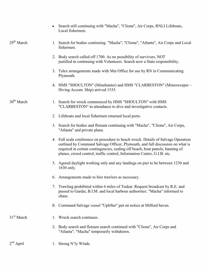
Search still continuing with "Macha", "Cliona", Air Corps, RNLI Lifeboats,
Local fishermen.
29th
March 1. Search for bodies continuing. "Macha", "Cliona", "Atlanta", Air Corps and Local
fishermen.
2. Body search called off 1700. As no possibility of survivors, NOT
justified in continuing with Volunteers. Search now a State responsibility.
3. Telex arrangements made with Met Office for use by RN in Communicating
Plymouth.
4. HMS "SHOULTON" (Minehunter) and HMS "CLARBESTON" (Minesweeper –
Diving Accom. Ship) arrived 1535.
30th
March 1. Search for wreck commenced by HMS "SHOULTON" with HMS
"CLARBESTON" in attendance to dive and investigative contacts.
2. Lifeboats and local fishermen returned local ports.
3. Search for bodies and flotsam continuing with "Macha", "Cliona", Air Corps,
"Atlanta" and private plane.
4. Full scale conference on procedure to beach wreck. Details of Salvage Operation
outlined by Command Salvage Officer, Plymouth, and full discussion on what is
required in certain contingencies, sealing off beach, boat patrols, banning of
planes, crowd control, traffic control, Information Centre, G.I.B. etc.
5. Agreed daylight working only and any landings on pier to be between 1230 and
1630 only.
6. Arrangements made to hire trawlers as necessary.
7. Trawling prohibited within 6 miles of Tuskar. Request broadcast by R.E. and
passed to Gardai, B.I.M. and local harbour authorities. "Macha" informed to
chase.
8. Command Salvage vessel "Uplifter" put on notice at Milford haven.
31st March 1. Wreck search continues.
2. Body search and flotsam search continued with "Cliona", Air Corps and
"Atlanta". "Macha" temporarily withdrawn.
2nd
April 1. Strong N’ly Winds.

2. No wreck search.
3. "Macha" and Air Corps Dove continuing body and wreckage search.
4. Air Corps personnel briefed at Baldonnel by CONS on conduct of search and
general intentions.
3rd
April `Surface search "Macha" and Air Corps Dove.
Bottom Search, H.M.S. "Shoulton"
4th
April Bottom Search, H.M.S. "Shoulton" and "Clarbeston" "Macha" and Air Corps Dove on
Surface Search.
5th
April Bottom search H.M.S. "Shoulton" and "Clarbeston" "Macha" and "Cu na Mara" on Tidal
Experiments.
From 5th
April onward, depending on weather pattern, HMS "SHOULTON" and HMS
"CLARBESTON" on bottom search either "Macha" or "Cliona" and "Cu na Mara" on tidal
experiments or surface search. Air Corps provided D and/or Helicopter on request for
particular searches.
16th
April M.T. "Glendalough" hired to carry out trawling operations in company with "Cu na Mara".
Trawling commenced.
20th
April HMS "SHOULTON" and HMS "CLARBESTON" returned Britain maintenance.
Trawling and Surface search continues with "Glendalough", "Cu na Mara", "Cliona" and
Air Corps.
3rd
May "Cu na Mara" withdrew to Dublin for winch repairs.
6th
May H.M.S. "SHOULTON" and HMS "CLARBESTON" returned to area and recommenced
bottom search.
16th
May "Cu na Mara" resumes trawling.
20th
May H.M.S. "CLARBESTON" withdrew to Plymouth.
C.S.V. "UPLIFTER" arrived with divers to replace "CLARBESTON".
21st May H.M.S. "Reclaim" arrived in area to assist H.M.S. "SHOULTON" in identifying contacts
by diving on them.

24th
May H.M.S. "RECLAIM" withdrawn temporarily.
29th
May H.M.S. "RECLAIM" returned area.
CSV "UPLIFTER" returned to Milford Haven.
5th
June 1200 "Glendalough" hauled in position 1.72’ from Tuskar with Tuskar bearing 280° in 39
fm and brought following wreckage to surface:-
a. Main fuselage 650 Station to part of Dorsal fin including Upper Main door frame,
Port Aft.
b. Galley Power Control Panel
c. Window frame believed to be the one immediately forward of main door.
d. Waste pipe from forward toilet.
1400 "Cu na Mara" hauled same position and got following:-
a. 3ft. length hat rack padded bar.
b. Unidentified piece – probably wing piece.
6th
June
1800 "Glendalough" hauled same position and brought up:-
a. Window rubber with handle from No.5 window, portside, from forward.
b. Primary silencer from pressurisation and air conditioning system position.
c. Small piece perspex window 2" x 2".
1400 "Glendalough" hauled same position and brought up:-
a. Part of forward main cabin door.
b. Main spar outer wing 7 ft. off.
c. Rolls Royce Dart Engine air intake.
d. Passenger Air conditioning panel.
e. Galley Hot Jug.
6th
June 1430 "Cu na Mara" hauled same position and brought up:-
a. Engine nacelle cowling.
b. Small piece of fuselage structure passenger window area.
H.M.S. "Reclaim" investigated position by diving.
Confirmed mass of wreckage – "like a scrap yard".
2330 Due to tides operations abandoned until Tuesday 11th
June "Cu na Mara" returned
Dublin to report back 1400 Tuesday 11th
. Glendalough returned Kilmore Quay to report
back 1400 Tuesday 11th
. "Shoulton" and "Reclaim" sailed for Plymouth.
"Cliona" returned Base.
7th
June
(1200)
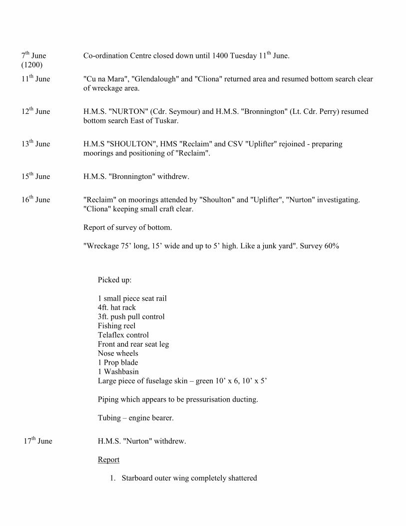
Co-ordination Centre closed down until 1400 Tuesday 11th
June.
11th
June "Cu na Mara", "Glendalough" and "Cliona" returned area and resumed bottom search clear
of wreckage area.
12th
June H.M.S. "NURTON" (Cdr. Seymour) and H.M.S. "Bronnington" (Lt. Cdr. Perry) resumed
bottom search East of Tuskar.
13th
June H.M.S "SHOULTON", HMS "Reclaim" and CSV "Uplifter" rejoined - preparing
moorings and positioning of "Reclaim".
15th
June H.M.S. "Bronnington" withdrew.
16th
June "Reclaim" on moorings attended by "Shoulton" and "Uplifter", "Nurton" investigating.
"Cliona" keeping small craft clear.
Report of survey of bottom.
"Wreckage 75’ long, 15’ wide and up to 5’ high. Like a junk yard". Survey 60%
Picked up:
1 small piece seat rail
4ft. hat rack
3ft. push pull control
Fishing reel
Telaflex control
Front and rear seat leg
Nose wheels
1 Prop blade
1 Washbasin
Large piece of fuselage skin – green 10’ x 6, 10’ x 5’
Piping which appears to be pressurisation ducting.
Tubing – engine bearer.
17th
June H.M.S. "Nurton" withdrew.
Report
1. Starboard outer wing completely shattered
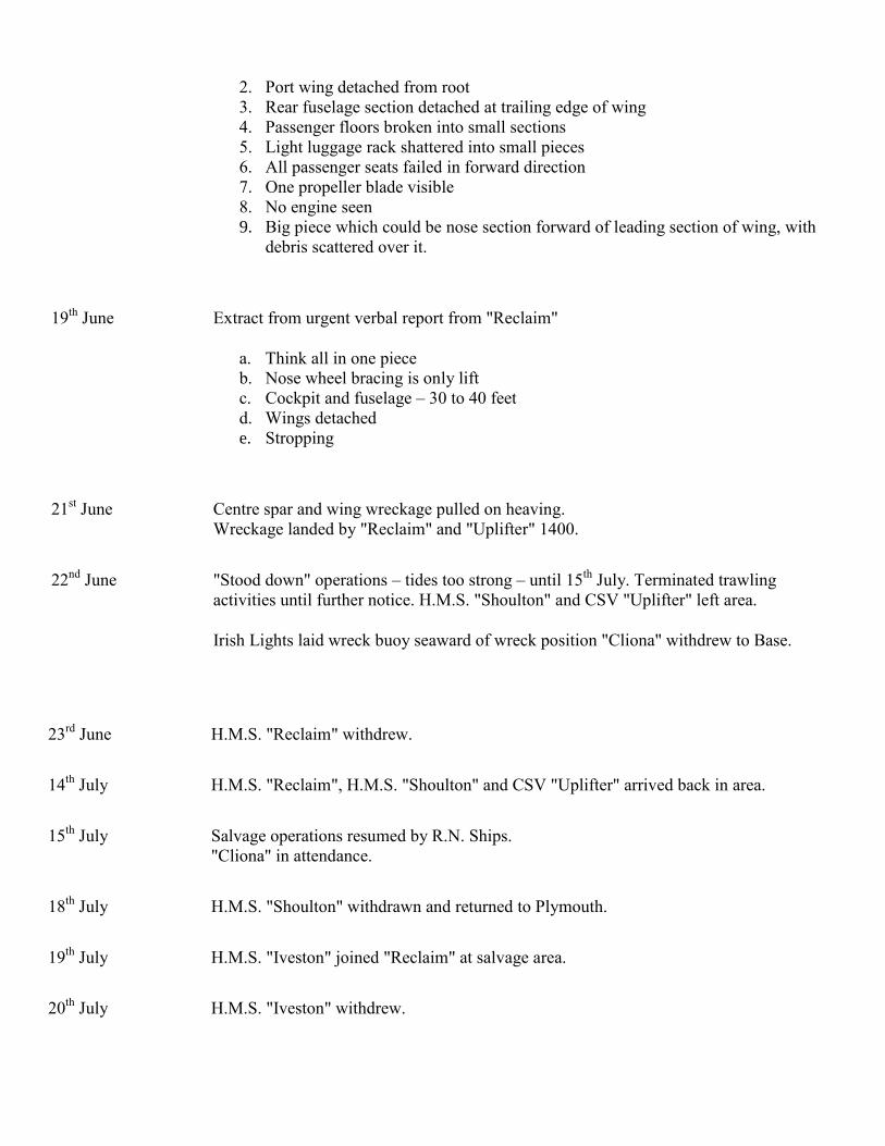
2. Port wing detached from root
3. Rear fuselage section detached at trailing edge of wing
4. Passenger floors broken into small sections
5. Light luggage rack shattered into small pieces
6. All passenger seats failed in forward direction
7. One propeller blade visible
8. No engine seen
9. Big piece which could be nose section forward of leading section of wing, with
debris scattered over it.
19th
June Extract from urgent verbal report from "Reclaim"
a. Think all in one piece
b. Nose wheel bracing is only lift
c. Cockpit and fuselage – 30 to 40 feet
d. Wings detached
e. Stropping
21st June Centre spar and wing wreckage pulled on heaving.
Wreckage landed by "Reclaim" and "Uplifter" 1400.
22nd
June "Stood down" operations – tides too strong – until 15th
July. Terminated trawling
activities until further notice. H.M.S. "Shoulton" and CSV "Uplifter" left area.
Irish Lights laid wreck buoy seaward of wreck position "Cliona" withdrew to Base.
23rd
June H.M.S. "Reclaim" withdrew.
14th
July H.M.S. "Reclaim", H.M.S. "Shoulton" and CSV "Uplifter" arrived back in area.
15th
July Salvage operations resumed by R.N. Ships.
"Cliona" in attendance.
18th
July H.M.S. "Shoulton" withdrawn and returned to Plymouth.
19th
July H.M.S. "Iveston" joined "Reclaim" at salvage area.
20th
July H.M.S. "Iveston" withdrew.
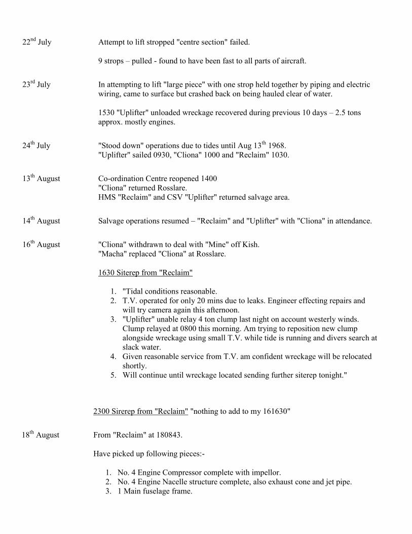
22nd
July Attempt to lift stropped "centre section" failed.
9 strops – pulled - found to have been fast to all parts of aircraft.
23rd
July In attempting to lift "large piece" with one strop held together by piping and electric
wiring, came to surface but crashed back on being hauled clear of water.
1530 "Uplifter" unloaded wreckage recovered during previous 10 days – 2.5 tons
approx. mostly engines.
24th
July "Stood down" operations due to tides until Aug 13th
1968.
"Uplifter" sailed 0930, "Cliona" 1000 and "Reclaim" 1030.
13th
August Co-ordination Centre reopened 1400
"Cliona" returned Rosslare.
HMS "Reclaim" and CSV "Uplifter" returned salvage area.
14th
August Salvage operations resumed – "Reclaim" and "Uplifter" with "Cliona" in attendance.
16th
August "Cliona" withdrawn to deal with "Mine" off Kish.
"Macha" replaced "Cliona" at Rosslare.
1630 Siterep from "Reclaim"
1. "Tidal conditions reasonable.
2. T.V. operated for only 20 mins due to leaks. Engineer effecting repairs and
will try camera again this afternoon.
3. "Uplifter" unable relay 4 ton clump last night on account westerly winds.
Clump relayed at 0800 this morning. Am trying to reposition new clump
alongside wreckage using small T.V. while tide is running and divers search at
slack water.
4. Given reasonable service from T.V. am confident wreckage will be relocated
shortly.
5. Will continue until wreckage located sending further siterep tonight."
2300 Sirerep from "Reclaim" "nothing to add to my 161630"
18th
August From "Reclaim" at 180843.
Have picked up following pieces:-
1. No. 4 Engine Compressor complete with impellor.
2. No. 4 Engine Nacelle structure complete, also exhaust cone and jet pipe.
3. 1 Main fuselage frame.
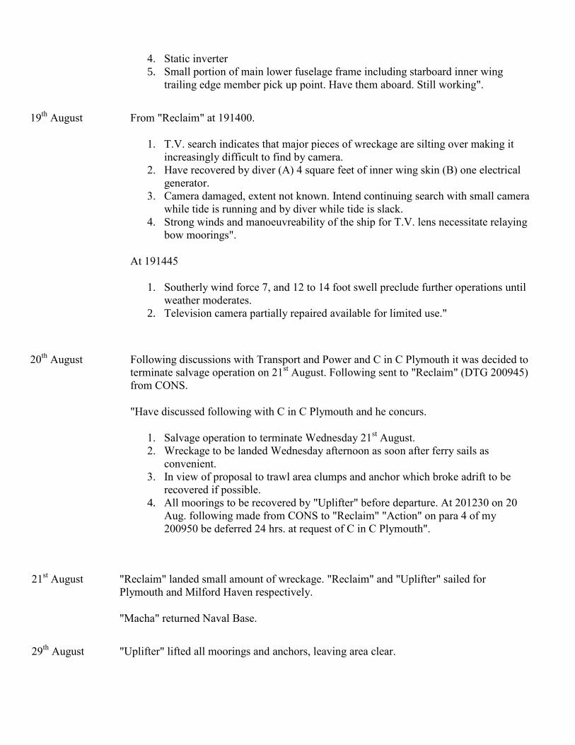
4. Static inverter
5. Small portion of main lower fuselage frame including starboard inner wing
trailing edge member pick up point. Have them aboard. Still working".
19th
August From "Reclaim" at 191400.
1. T.V. search indicates that major pieces of wreckage are silting over making it
increasingly difficult to find by camera.
2. Have recovered by diver (A) 4 square feet of inner wing skin (B) one electrical
generator.
3. Camera damaged, extent not known. Intend continuing search with small camera
while tide is running and by diver while tide is slack.
4. Strong winds and manoeuvreability of the ship for T.V. lens necessitate relaying
bow moorings".
At 191445
1. Southerly wind force 7, and 12 to 14 foot swell preclude further operations until
weather moderates.
2. Television camera partially repaired available for limited use."
20th
August Following discussions with Transport and Power and C in C Plymouth it was decided to
terminate salvage operation on 21st August. Following sent to "Reclaim" (DTG 200945)
from CONS.
"Have discussed following with C in C Plymouth and he concurs.
1. Salvage operation to terminate Wednesday 21st August.
2. Wreckage to be landed Wednesday afternoon as soon after ferry sails as
convenient.
3. In view of proposal to trawl area clumps and anchor which broke adrift to be
recovered if possible.
4. All moorings to be recovered by "Uplifter" before departure. At 201230 on 20
Aug. following made from CONS to "Reclaim" "Action" on para 4 of my
200950 be deferred 24 hrs. at request of C in C Plymouth".
21st August "Reclaim" landed small amount of wreckage. "Reclaim" and "Uplifter" sailed for
Plymouth and Milford Haven respectively.
"Macha" returned Naval Base.
29th
August "Uplifter" lifted all moorings and anchors, leaving area clear.
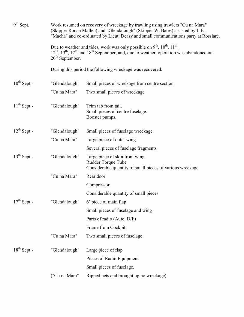
9th
Sept. Work resumed on recovery of wreckage by trawling using trawlers "Cu na Mara"
(Skipper Ronan Mallen) and "Glendalough" (Skipper W. Bates) assisted by L.E.
"Macha" and co-ordinated by Lieut. Deasy and small communications party at Rosslare.
Due to weather and tides, work was only possible on 9th
, 10th
, 11th
,
12th
, 13th
, 17th
and 18th
September, and, due to weather, operation was abandoned on
20th
September.
During this period the following wreckage was recovered:
10th
Sept - "Glendalough" Small pieces of wreckage from centre section.
"Cu na Mara" Two small pieces of wreckage.
11th
Sept - "Glendalough" Trim tab from tail.
Small pieces of centre fuselage.
Booster pumps.
12th
Sept - "Glendalough" Small pieces of fuselage wreckage.
"Cu na Mara" Large piece of outer wing
Several pieces of fuselage fragments
13th
Sept - "Glendalough" Large piece of skin from wing
Rudder Torque Tube
Considerable quantity of small pieces of various wreckage.
"Cu na Mara" Rear door
Compressor
Considerable quantity of small pieces
17th
Sept - "Glendalough" 6’ piece of main flap
Small pieces of fuselage and wing
Parts of radio (Auto. D/F)
Frame from Cockpit.
"Cu na Mara" Two small pieces of fuselage
18th
Sept - "Glendalough" Large piece of flap
Pieces of Radio Equipment
Small pieces of fuselage.
("Cu na Mara" Ripped nets and brought up no wreckage)

27th
Sept Due to very valuable evidence recovered between 9th
and 18th
Sept it was decided to
continue for a further eight days from 27th
Sept to 4th
October.
Vessels employed "Cu na Mara" and "Glendalough" assisted by L.E. "Macha". Co-
ordination under Lieut Deasy and Communication Party ashore.
Due to weather no work was possible from Friday 27th
Sept to Tuesday 1st Oct
inclusive. Trawling took place on 2nd
, 3rd
and 4th
Oct 1968, when tides forced
abandonment.
During this period following wreckage recovered.
30th
Sept "Cu na Mara" 1 small piece of frame
1st October Crew member of "Glendalough" handed up a portion of an elevator spring tab – 2’
long by 8" wide – which he picked up on beach.
2nd
October "Glendalough" Small pieces of retractable under-carriage
Pieces from engines
Several pieces of panelling
3rd
October "Glendalough" Auxiliary Cockpit seat
Parts of panel control from cockpit
Door frame – port side
Small pieces of fuselage, pipes and wiring
"Cu na Mara" Heat exchanger
Pieces of engine, frames fuselage and pipe
4th
October "Cu na Mara" 2 ton of Cockpit
"Glendalough" Small quantity pipes etc.
Operation Tuskar ended at 1625 on 4th
October 1968 with landing of wreckage. L.E. "Macha" returned
Base, "Glendalough" returned Kilmore Quay and "Cu na Mara" towards Dublin.
Communication and Co-ordination Party cleared up ashore on 5th
Oct and returned Naval Base.
17th
October Irish Lights vessel "GRANUAILE" recovered Wreck Buoy established East of wreck
site.
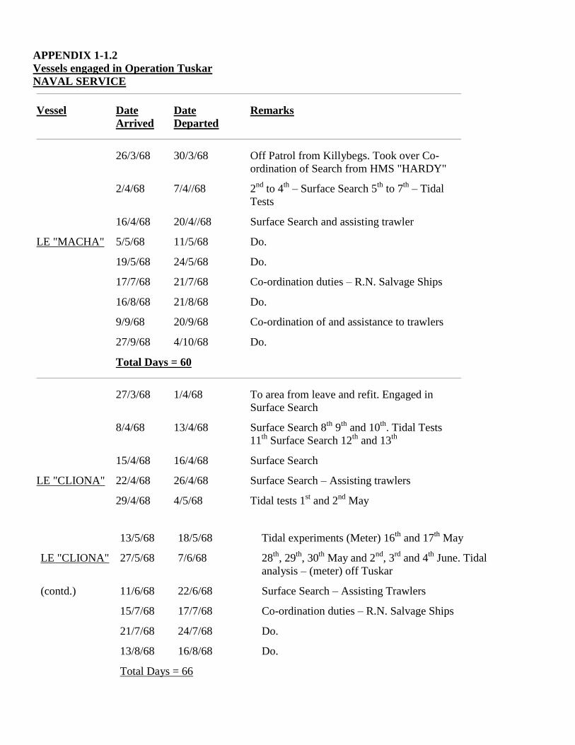
APPENDIX 1-1.2
Vessels engaged in Operation Tuskar
NAVAL SERVICE
Vessel Date
Arrived
Date
Departed
Remarks
26/3/68 30/3/68 Off Patrol from Killybegs. Took over Co-
ordination of Search from HMS "HARDY"
2/4/68 7/4//68 2nd
to 4th
– Surface Search 5th
to 7th
– Tidal
Tests
16/4/68 20/4//68 Surface Search and assisting trawler
LE "MACHA" 5/5/68 11/5/68 Do.
19/5/68 24/5/68 Do.
17/7/68 21/7/68 Co-ordination duties – R.N. Salvage Ships
16/8/68 21/8/68 Do.
9/9/68 20/9/68 Co-ordination of and assistance to trawlers
27/9/68 4/10/68 Do.
Total Days = 60
27/3/68 1/4/68 To area from leave and refit. Engaged in
Surface Search
8/4/68 13/4/68 Surface Search 8th
9th
and 10th
. Tidal Tests
11th
Surface Search 12th
and 13th
15/4/68 16/4/68 Surface Search
LE "CLIONA" 22/4/68 26/4/68 Surface Search – Assisting trawlers
29/4/68 4/5/68 Tidal tests 1st and 2
nd May
13/5/68 18/5/68 Tidal experiments (Meter) 16th
and 17th
May
LE "CLIONA" 27/5/68 7/6/68 28th
, 29th
, 30th
May and 2nd
, 3rd
and 4th
June. Tidal
analysis – (meter) off Tuskar
(contd.) 11/6/68 22/6/68 Surface Search – Assisting Trawlers
15/7/68 17/7/68 Co-ordination duties – R.N. Salvage Ships
21/7/68 24/7/68 Do.
13/8/68 16/8/68 Do.
Total Days = 66

ROYAL NAVY
Vessel Date Arrived Date Departed Remarks
29/3/68 20/4/68 Bottom Sonar Search
HMS SHOULTON" 9/5/68 7/6/68 Do.
13/6/68 22/6/68 Directing "Reclaim" on to wreck and conning.
15/7/68 18/7/68 Do.
HMS
"CLARBESTON"
29/3/68 20/4/68 Diving Ship – Investigating Contacts
9/5/68 20/5/68
21/5/68 29/5/68 Available in lieu of "CLARBESTON". 24th
, 25th
,
26th
, 27th
and 28th
– Tidal Analysis – 2’ NE of
Tuskar.
C.S.V. "UPLIFTER" 13/6/68 22/6/68 Laying moorings and attending "Reclaim" on
Salvage.
12/7/68 24/7/68 Do.
12/8/68 21/8/68 Do.
21/5/68 24/5/68 Investigating Contacts by Diver
29/5/68 7/6/68 Do.
HMS "RECLAIM" 13/6/68 23/6/68 Salvage operations in wreck
15/7/68 24/7/68 Do.
13/8/68 21/8/68 Do.
HMS "NURTON" 12/6/68 17/6/68 Bottom Sonar Search – Investigating Contacts.
HMS
"BRONNINGTON"
12/6/68 15/6/68 Bottom Sonar Search – Investigating Contacts.
HMS "IVESTON" 19/7/68 20/7/68 Directing "Reclaim" on to wreck

TRAWLERS
Vessel Date
Arrived
Date
Departed
Remarks
M.F.V. "Cu na
Mara"
4/4/68 5/4/68 Tidal Experiments (Tyres)
8/4/68 9/4/68 Preparing for Trawling
16/4/68 26/4/68 Trawling by search of Aircraft wreck
29/4/68 3/5/68 Do. (Winch U.S. on 3rd
– returned Dublin for
repairs until 16th
May)
16/5/68 7/6/68 Trawling in search of Aircraft wreckage
12/6/68 22/6/68 Trawling in search of Aircraft wreckage clear of
main wreck
9/9/68 20/9/68 Trawling for wreckage on site of main wreck
29/9/68 4/10/68 Do.
Total Days=73
M.F.V.
"Glendalough"
16/4/68 26/4/68 Trawling in search of Aircraft wreckage
29/4/68 7/6/68 Do. Main wreck located by "Glendalough" 5th
June, 1968
12/6/68 22/6/68 Trawling in search of Aircraft wreckage clear of
main wreck
9/9/68 20/9/68 Trawling for wreckage on site of main wreck
28/9/68 4/10/68 Do.
Total Days=81
Commissioners of Irish Lights Vessel
M.V. "ATLANTA" 29/4/68 5/5/68 Surface Search
22/6/68 Laying wreck Buoy East of Main wreck
M.V.
"GRANUAILE"
17/10/68 Recovering Wreck Buoy
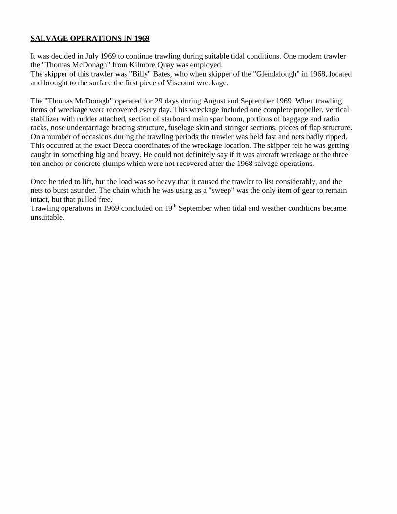
SALVAGE OPERATIONS IN 1969
It was decided in July 1969 to continue trawling during suitable tidal conditions. One modern trawler
the "Thomas McDonagh" from Kilmore Quay was employed.
The skipper of this trawler was "Billy" Bates, who when skipper of the "Glendalough" in 1968, located
and brought to the surface the first piece of Viscount wreckage.
The "Thomas McDonagh" operated for 29 days during August and September 1969. When trawling,
items of wreckage were recovered every day. This wreckage included one complete propeller, vertical
stabilizer with rudder attached, section of starboard main spar boom, portions of baggage and radio
racks, nose undercarriage bracing structure, fuselage skin and stringer sections, pieces of flap structure.
On a number of occasions during the trawling periods the trawler was held fast and nets badly ripped.
This occurred at the exact Decca coordinates of the wreckage location. The skipper felt he was getting
caught in something big and heavy. He could not definitely say if it was aircraft wreckage or the three
ton anchor or concrete clumps which were not recovered after the 1968 salvage operations.
Once he tried to lift, but the load was so heavy that it caused the trawler to list considerably, and the
nets to burst asunder. The chain which he was using as a "sweep" was the only item of gear to remain
intact, but that pulled free.
Trawling operations in 1969 concluded on 19th
September when tidal and weather conditions became
unsuitable.

Appendix 2:
Transcripts of tape recordings of R/T exchanges between EI-AOM and Air Traffic Services (Air
Traffic Control Services).
Transcription from Tape Recording of communications between ALT712, EI-AOM, and Air Traffic
Control, Cork Airport, Sunday 24th
March 1968.
Time
G.M.T. From To
1026 EI712 TWR. 712 Start.
1026 TWR 712 712 cleared to start, QNH 998 Temp. plus 08
1030 EI712 TWR Taxi Clearance?
1030 EI712 TWR TAXI?
1031 TWR 712 712 cleared to taxi, RW17
1031 TWR 712 A.T.C
1031 EI712 TWR Go ahead
1031 TWR 712 Aer Lingus 712 is cleared Cork to London Airport airways Blue 10
Green 1 Flight level 170.
1031 EI712 TWR Blue 10 Green 1 170.
1031 TWR 712 Your climb out will be left turn out climbing on radial 102 until
through Flight Level 100 on course.
1031 EI712 TWR Roger left turn out radial 102 until 100 then on course
1031 TWR 712 Your traffic is a Herald inbound on radial 087 estimating Youghal
46 descending to 50.
1031 EI712 TWR Roger
1032 TWR 712 Cleared takeoff left turn out climb radial 102 wind 200/13 knots.
1032 EI712 TWR Left turn out on to radial 102
1033 TWR 712 712 was airborne at 32 contact Approach 119.3
1033 EI712 TWR Roger
1034 EI712 TWR Cork Approach 712
1034 App. 712 Climb as instructed call passing flights level 70 please.
1034 EI712 APP. Roger will call passing 70
1035 GWC APP. Cork Whiskey Charlie is passing 70
1035 APP. GWC OK Whiskey Charlie advise again out of 60
1035 GWC APP Roger will do
1036 APP 712 712 Present level?
1036 EI712 App 60 climbing to 170
1037 APP 712 When out of 70 712 is cleared turn left on course for Tuskar
1037 EI712 APP Roger D
1038 EI712 App 712 out of 70
1038 APP 712 Roger 712 cleared on course now change to Shannon 127.5 Over
1039 EI712 App Cheerio
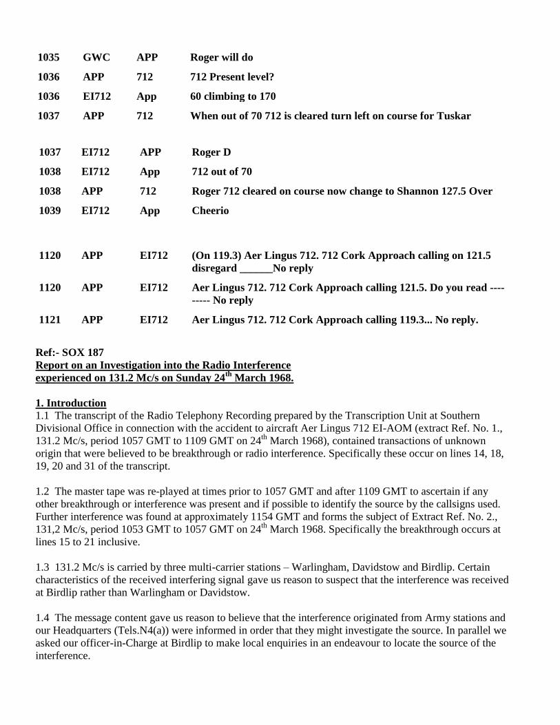
1120 APP EI712 (On 119.3) Aer Lingus 712. 712 Cork Approach calling on 121.5
disregard ______No reply
1120 APP EI712 Aer Lingus 712. 712 Cork Approach calling 121.5. Do you read ----
----- No reply
1121 APP EI712 Aer Lingus 712. 712 Cork Approach calling 119.3... No reply.
Ref:- SOX 187
Report on an Investigation into the Radio Interference
experienced on 131.2 Mc/s on Sunday 24th
March 1968.
1. Introduction
1.1 The transcript of the Radio Telephony Recording prepared by the Transcription Unit at Southern
Divisional Office in connection with the accident to aircraft Aer Lingus 712 EI-AOM (extract Ref. No. 1.,
131.2 Mc/s, period 1057 GMT to 1109 GMT on 24th
March 1968), contained transactions of unknown
origin that were believed to be breakthrough or radio interference. Specifically these occur on lines 14, 18,
19, 20 and 31 of the transcript.
1.2 The master tape was re-played at times prior to 1057 GMT and after 1109 GMT to ascertain if any
other breakthrough or interference was present and if possible to identify the source by the callsigns used.
Further interference was found at approximately 1154 GMT and forms the subject of Extract Ref. No. 2.,
131,2 Mc/s, period 1053 GMT to 1057 GMT on 24th
March 1968. Specifically the breakthrough occurs at
lines 15 to 21 inclusive.
1.3 131.2 Mc/s is carried by three multi-carrier stations – Warlingham, Davidstow and Birdlip. Certain
characteristics of the received interfering signal gave us reason to suspect that the interference was received
at Birdlip rather than Warlingham or Davidstow.
1.4 The message content gave us reason to believe that the interference originated from Army stations and
our Headquarters (Tels.N4(a)) were informed in order that they might investigate the source. In parallel we
asked our officer-in-Charge at Birdlip to make local enquiries in an endeavour to locate the source of the
interference.
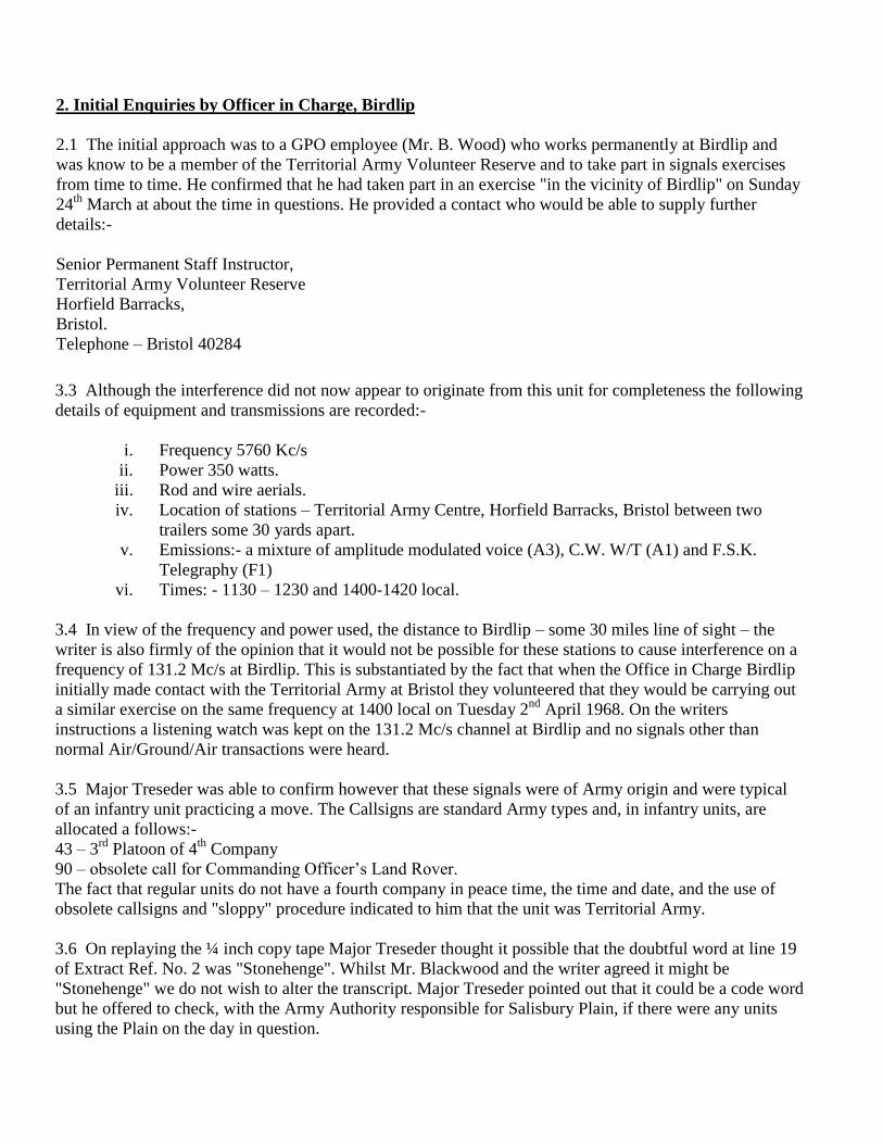
2. Initial Enquiries by Officer in Charge, Birdlip
2.1 The initial approach was to a GPO employee (Mr. B. Wood) who works permanently at Birdlip and
was know to be a member of the Territorial Army Volunteer Reserve and to take part in signals exercises
from time to time. He confirmed that he had taken part in an exercise "in the vicinity of Birdlip" on Sunday
24th
March at about the time in questions. He provided a contact who would be able to supply further
details:-
Senior Permanent Staff Instructor,
Territorial Army Volunteer Reserve
Horfield Barracks,
Bristol.
Telephone – Bristol 40284
3.3 Although the interference did not now appear to originate from this unit for completeness the following
details of equipment and transmissions are recorded:-
i. Frequency 5760 Kc/s
ii. Power 350 watts.
iii. Rod and wire aerials.
iv. Location of stations – Territorial Army Centre, Horfield Barracks, Bristol between two
trailers some 30 yards apart.
v. Emissions:- a mixture of amplitude modulated voice (A3), C.W. W/T (A1) and F.S.K.
Telegraphy (F1)
vi. Times: - 1130 – 1230 and 1400-1420 local.
3.4 In view of the frequency and power used, the distance to Birdlip – some 30 miles line of sight – the
writer is also firmly of the opinion that it would not be possible for these stations to cause interference on a
frequency of 131.2 Mc/s at Birdlip. This is substantiated by the fact that when the Office in Charge Birdlip
initially made contact with the Territorial Army at Bristol they volunteered that they would be carrying out
a similar exercise on the same frequency at 1400 local on Tuesday 2nd
April 1968. On the writers
instructions a listening watch was kept on the 131.2 Mc/s channel at Birdlip and no signals other than
normal Air/Ground/Air transactions were heard.
3.5 Major Treseder was able to confirm however that these signals were of Army origin and were typical
of an infantry unit practicing a move. The Callsigns are standard Army types and, in infantry units, are
allocated a follows:-
43 – 3rd
Platoon of 4th
Company
90 – obsolete call for Commanding Officer’s Land Rover.
The fact that regular units do not have a fourth company in peace time, the time and date, and the use of
obsolete callsigns and "sloppy" procedure indicated to him that the unit was Territorial Army.
3.6 On replaying the ¼ inch copy tape Major Treseder thought it possible that the doubtful word at line 19
of Extract Ref. No. 2 was "Stonehenge". Whilst Mr. Blackwood and the writer agreed it might be
"Stonehenge" we do not wish to alter the transcript. Major Treseder pointed out that it could be a code word
but he offered to check, with the Army Authority responsible for Salisbury Plain, if there were any units
using the Plain on the day in question.

Only one Army unit did in fact use the Plain on Sunday 24th
March 1968, and that was the 1st
Worcestershire Regiment. After some difficulty the second in command of this Regiment was contacted
and it was confirmed that they did not use the callsigns in question. They do not have a fourth company in
peacetime. It is, of course, rather unlikely that any radio transmissions made on Salisbury Plain – some 45
miles from Birdlip could cause interference.
3.7 The writer asked Major Treseder if he could explain the Radio Telephony transactions that were
attributable to the Army. Lines 15 to 21 on Extract Ref. No. 2 were stated to be typical of an Infantry
Regiment practicing a move. It was though possible that no first call was heard from 43 because the stations
were mobile. Turning now to Extract Ref. No. 1 the part phrase – "Charlie will you move-" at line 14 is
again Army procedure the callsign Charlie should be proceeded by a numeral. The phrase "-breaking up
over-" at line 18 was, in Major Tresseders opinion, a reference to breaking camp and "-on standby calling
you over-" a reference to use of standby equipment to control the movement en route.
The word "-finished –" at line 31 would appear to be of Army origin although it is, of course, difficult to be
certain on one isolated word.
3.8 A general discussion followed in which the writer and Major Treseder, came to the conclusion that the
only possible method to trace the actual source of interference was to start with the appropriate section in
Ministry of Defence (Army).
4. Summary and Conclusions
4.1 The source of the breakthrough at lines 14, 18, 19 and 20 has been shown to be of Army origin. The
work at line 31 probable originates from the same source.
4.2 It was not possible to identify the actual source of the interference and if this is required it will be
necessary for Tel. Headquarters (Tels. N4) to approach the Ministry of Defence (Army).
4.3 An explanation of certain words and the Radio Telephony procedures has been obtained from Officers
of the Royal Signals Regiment although these were not the personnel actually making the transmission.
4.4 Subsequent to the visit to Horfield Barracks it has been ascertained that the Army do have frequency
allocations in the band 41 – 68 Mc/s for low power land mobile use. This opens up the possibility of second
or third harmonic interference although the source of this would have to be quite near to our receiving
station. It should be noted that use of those frequencies by the Army is subject to agreement between the
General Post Office and Ministry of Defence (Army).
A.L. Stratten.
Telecommunications
Civil Aviation Divisional Office.
Heston.
23rd
April, 1968

Air Traffic Services,
DUBLIN AIRPORT
26th
March, 1968.
EI 362 DUBLIN/BRISTOL 24th
MARCH, 1968
Time From To Text
1041 362 Dublin Centre Dublin Centre good morning, 326
1041 Dublin Centre 362 Good morning, check Killiney.
1041 362 Dublin Centre 362.
1043.5 Dublin Centre 362 362, I make you at Killiney, check cruising 130.
1043.5 362 Dublin Centre Roger 362
1053 Dublin Centre 362 If you are using the Dublin VOR it is gone off the air,
you have just twelve miles to run to Vartry , on the
airway centre line.
1053 362 Dublin Centre 362 Roger, just levelling now at 130.
1055.56 362 Dublin Centre Dublin Centre Aer Lingus 362 by Vartry at 56, level
130, Strunble 05.
1056 Dublin Centre 362 Thank you very much 362, that all checks, would you
change to London now please 131.2.
1056.11 362 Dublin Centre 131.2, 362 Good morning.
1056.13 Dublin Centre 362 Good Morning Gentlemen. Pleasant flight.
Certified: E.D. McConville ATCO III.
Air Traffic Services,
Shannon Airport.
Transcript of Recording of the Shannon – London telephone Line
on Sunday 24th
March, 1968
Period: 1036 to 1044 (GMT
Time From To Text
1036 Shannon London Hello One estimate Aer Lingus 712
London Shannon On who? Aer Lingus 712? I have got 172. Is this 712
that’s Cork to London
Shannon London Cork to London. That’s right
London Shannon It’s 712 not 172?
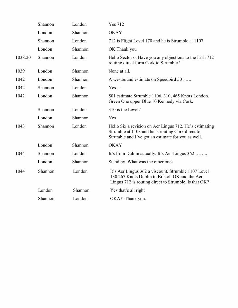
Shannon London Yes 712
London Shannon OKAY
Shannon London 712 is Flight Level 170 and he is Strumble at 1107
London Shannon OK Thank you
1038:20 Shannon London Hello Sector 6. Have you any objections to the Irish 712
routing direct form Cork to Strumble?
1039 London Shannon None at all.
1042 London Shannon A westbound estimate on Speedbird 501 ….
1042 Shannon London Yes….
1042 London Shannon 501 estimate Strumble 1106, 310, 465 Knots London.
Green One upper Blue 10 Kennedy via Cork.
Shannon London 310 is the Level?
London Shannon Yes
1043 Shannon London Hello Six a revision on Aer Lingus 712. He’s estimating
Strumble at 1103 and he is routing Cork direct to
Strumble and I’ve got an estimate for you as well.
London Shannon OKAY
1044 Shannon London It’s from Dublin actually. It’s Aer Lingus 362 ……..
London Shannon Stand by. What was the other one?
1044 Shannon London It’s Aer Lingus 362 a viscount. Strumble 1107 Level
130 267 Knots Dublin to Bristol. OK and the Aer
Lingus 712 is routing direct to Strumble. Is that OK?
London Shannon Yes that’s all right
Shannon London OKAY Thank you.

Aer Lingus Flight EI 712 Cork-London
On
March 24, 1968
This is a certified transcript of recording of R/T transmission on Shannon Area Control frequency 127.5
m/cs during the period 1039 to 1057 GMT inclusive on Sunday, March 24, 1968.
(signed): M. Moloney
(Senior Air Traffic
Control Officer).
Date: 25 March, 1968 Shannon Airport
Time From To Text
1039:45 EI 712 Shannon Shannon 712 good morning
Shannon EI 712 712 good morning
712 Shannon By Youghal passing through 75 climbing to 170 Tuskar 57
1040:00 Shannon 712 Roger 712 if you wish you may route direct to Strumble go ahead
712 Shannon (Unreadable)
Shannon 712 Your transmission are fairly unreadable here confirm you are accepting
a direct routing to Strumble
712 Shannon Affirmative estimating Strumble at 03.
Shannon 712 Roger call cruising.
1041:20 Shannon 712 Your present level
712 Shannon 712 is passing 90.
Shannon 712 Roger arrange your climb to cross the boundary at 170.
712 Shannon (Unreadable).
1042:12 GAPMC Shannon Request permission return to Shannon flight level 100 over.
Shannon GAPMC Cleared return Shannon maintain 100 report Foynes.
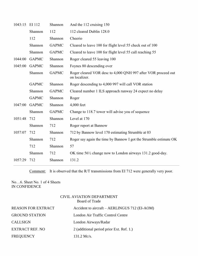
1043:15 EI 112 Shannon And the 112 cruising 150
Shannon 112 112 cleared Dublin 128.0
112 Shannon Cheerio
Shannon GAPMC Cleared to leave 100 for flight level 55 check out of 100
Shannon GAPMC Cleared to leave 100 for flight level 55 call reaching 55
1044:00 GAPMC Shannon Roger cleared 55 leaving 100
1045:00 GAPMC Shannon Foynes 80 descending over
Shannon GAPMC Roger cleared VOR desc to 4,000 QNH 997 after VOR proceed out
on localizer.
GAPMC Shannon Roger descending to 4,000 997 will call VOR station
Shannon GAPMC Cleared number 1 ILS approach runway 24 expect no delay
GAPMC Shannon Roger
1047:00 GAPMC Shannon 4,000 feet
Shannon GAPMC Change to 118.7 tower will advise you of sequence
1051:48 712 Shannon Level at 170
Shannon 712 Roger report at Bannow
1057:07 712 Shannon 712 by Bannow level 170 estimating Strumble at 03
Shannon 712 Roger say again the time by Bannow I got the Strumble estimate OK
712 Shannon 57
Shannon 712 OK time 56½ change now to London airways 131.2 good-day.
1057:29 712 Shannon 131.2
Comment: It is observed that the R/T transmissions from EI 712 were generally very poor.
No…6. Sheet No. 1 of 4 Sheets
IN CONFIDENCE
CIVIL AVIATION DEPARTMENT
Board of Trade
REASON FOR EXTRACT Accident to aircraft – AERLINGUS 712 (EI-AOM)
GROUND STATION London Air Traffic Control Centre
CALLSIGN London Airways/Radar
EXTRACT REF. NO 2 (additional period prior Ext. Ref. 1.)
FREQUENCY 131.2 Mc/s.

FACILITY AIRWAYS
TYPE OF LOG Radiotelephony Recording
PERIOD COVERED BY EXTRACT From 1053 GMT on 24th
March, 1968.
To 1057 GMT on 24th
March, 1968
NOTES:
1. Time Signals may be injected into the recorder by the following methods:-
a. Orally by B. of T. personnel.
b. Automatically by a time injection unit in the form of three letter morse signals.
These signals may or may not occur simultaneously with speech, but for clarity the three letters are
bracketed together and entered either in their correct position or immediately after the work in which the
time signal occurred.
2. All time signals appearing in Column 4 are entered in Column 5, including the decode of the
automatically injected signals to assist in the interpretation of the log.
3. The entries in Columns 2 and 3 have also been made to assist in the interpretation of the log and they do
not necessarily occur on the recording, either in the form given or in any other form. Where they do not
appear in the form given or in any form in Column 4 the entries in Columns 2 and 3 represent the opinion of
the transcriber and are based on his knowledge of the recording.
4. All significant pauses in a message are indicated by a space of about half an inch. Where possible the
duration of the pause is given in the "Remarks" column.
5. Words which are doubtful are indicated in Column 4 by a series of questions marks at the appropriate
place. When possible the duration or number of such words and/or a probable interpretation of them is given
in the "Remarks" column.
6. Works which are unintelligible are indicated in Column 4 by a series of questions marks at the
appropriate place. In addition, the word "Unintelligible" and if possible the number or duration of the
missing words are entered in the "Remarks" column.
2nd
April, 1968.
F.A. Abbott
…………………………………
Officer i/c., Transcription Unit,
Southern Divisional Office, Heston
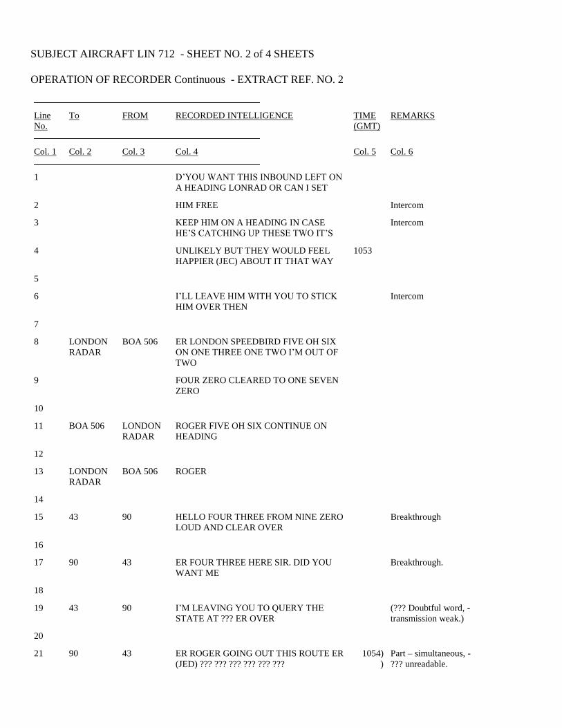
SUBJECT AIRCRAFT LIN 712 - SHEET NO. 2 of 4 SHEETS
OPERATION OF RECORDER Continuous - EXTRACT REF. NO. 2
Line
No. To FROM RECORDED INTELLIGENCE TIME
(GMT) REMARKS
Col. 1 Col. 2 Col. 3 Col. 4 Col. 5 Col. 6
1 D’YOU WANT THIS INBOUND LEFT ON
A HEADING LONRAD OR CAN I SET
2 HIM FREE Intercom
3 KEEP HIM ON A HEADING IN CASE
HE’S CATCHING UP THESE TWO IT’S Intercom
4 UNLIKELY BUT THEY WOULD FEEL
HAPPIER (JEC) ABOUT IT THAT WAY 1053
5
6 I’LL LEAVE HIM WITH YOU TO STICK
HIM OVER THEN Intercom
7
8 LONDON
RADAR BOA 506 ER LONDON SPEEDBIRD FIVE OH SIX
ON ONE THREE ONE TWO I’M OUT OF
TWO
9 FOUR ZERO CLEARED TO ONE SEVEN
ZERO
10
11 BOA 506 LONDON
RADAR ROGER FIVE OH SIX CONTINUE ON
HEADING
12
13 LONDON
RADAR BOA 506 ROGER
14
15 43 90 HELLO FOUR THREE FROM NINE ZERO
LOUD AND CLEAR OVER Breakthrough
16
17 90 43 ER FOUR THREE HERE SIR. DID YOU
WANT ME Breakthrough.
18
19 43 90 I’M LEAVING YOU TO QUERY THE
STATE AT ??? ER OVER (??? Doubtful word, -
transmission weak.)
20
21 90 43 ER ROGER GOING OUT THIS ROUTE ER
(JED) ??? ??? ??? ??? ??? ??? 1054)
)
Part – simultaneous, -
??? unreadable.
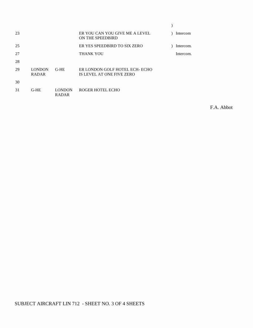
)
23 ER YOU CAN YOU GIVE ME A LEVEL
ON THE SPEEDBIRD ) Intercom
25 ER YES SPEEDBIRD TO SIX ZERO ) Intercom.
27 THANK YOU Intercom.
28
29 LONDON
RADAR G-HE ER LONDON GOLF HOTEL ECH- ECHO
IS LEVEL AT ONE FIVE ZERO
30
31 G-HE LONDON
RADAR ROGER HOTEL ECHO
F.A. Abbot
SUBJECT AIRCRAFT LIN 712 - SHEET NO. 3 OF 4 SHEETS
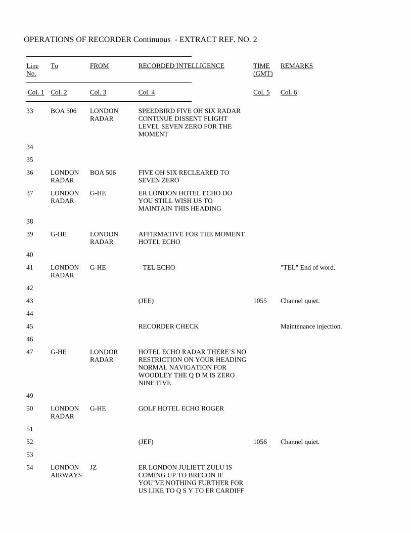
OPERATIONS OF RECORDER Continuous - EXTRACT REF. NO. 2
Line
No. To FROM RECORDED INTELLIGENCE TIME
(GMT) REMARKS
Col. 1 Col. 2 Col. 3 Col. 4 Col. 5 Col. 6
33 BOA 506 LONDON
RADAR SPEEDBIRD FIVE OH SIX RADAR
CONTINUE DISSENT FLIGHT
LEVEL SEVEN ZERO FOR THE
MOMENT
34
35
36 LONDON
RADAR BOA 506 FIVE OH SIX RECLEARED TO
SEVEN ZERO
37 LONDON
RADAR G-HE ER LONDON HOTEL ECHO DO
YOU STILL WISH US TO
MAINTAIN THIS HEADING
38
39 G-HE LONDON
RADAR AFFIRMATIVE FOR THE MOMENT
HOTEL ECHO
40
41 LONDON
RADAR G-HE --TEL ECHO "TEL" End of word.
42
43 (JEE) 1055 Channel quiet.
44
45 RECORDER CHECK Maintenance injection.
46
47 G-HE LONDOR
RADAR HOTEL ECHO RADAR THERE’S NO
RESTRICTION ON YOUR HEADING
NORMAL NAVIGATION FOR
WOODLEY THE Q D M IS ZERO
NINE FIVE
49
50 LONDON
RADAR G-HE GOLF HOTEL ECHO ROGER
51
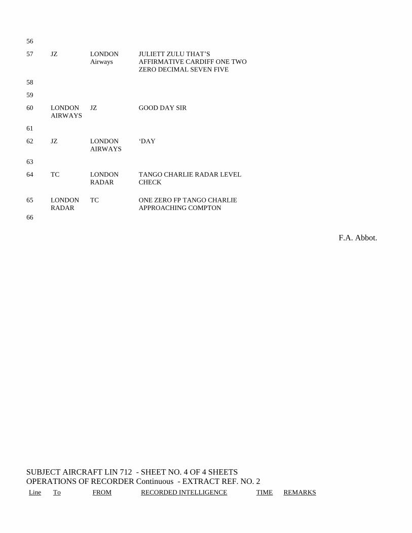
52 (JEF) 1056 Channel quiet.
53
54 LONDON
AIRWAYS JZ ER LONDON JULIETT ZULU IS
COMING UP TO BRECON IF
YOU’VE NOTHING FURTHER FOR
US LIKE TO Q S Y TO ER CARDIFF
56
57 JZ LONDON
Airways JULIETT ZULU THAT’S
AFFIRMATIVE CARDIFF ONE TWO
ZERO DECIMAL SEVEN FIVE
58
59
60 LONDON
AIRWAYS JZ GOOD DAY SIR
61
62 JZ LONDON
AIRWAYS ‘DAY
63
64 TC LONDON
RADAR TANGO CHARLIE RADAR LEVEL
CHECK
65
66
LONDON
RADAR TC ONE ZERO FP TANGO CHARLIE
APPROACHING COMPTON
F.A. Abbot.
SUBJECT AIRCRAFT LIN 712 - SHEET NO. 4 OF 4 SHEETS
OPERATIONS OF RECORDER Continuous - EXTRACT REF. NO. 2
Line To FROM RECORDED INTELLIGENCE TIME REMARKS

No. (GMT)
Col. 1 Col. 2 Col. 3 Col. 4 Col. 5 Col. 6
68 TC LONDON
RADAR ‘KYOU
69
70 TC LONDON
RADAR TANGO CHARLIE THERE’S NO
RESTRICTION ON YOUR HEADING
FOR WOODLEY YOUR PRESENT
HEADING ??? ??? GOOD AND I
MAKE YOU ER SEVEN MILES TO
GO
??? Unintelligible.
72
73 LONDON
RADAR TC TANGO CHARLIE THANK YOU
74
75 LONDON
AIRWAYS LIN 326 LONDON AIRWAYS AERLINGUS
THREE SIX TWO
76
77 LIN 362 LONDON
AIRWAYS (JEG) THREE SIX TWO AIRWAYS 1057
78
79 LONDON
AIRWAYS LIN 362 AERLINGUS THREE SIX TWO IS BY
VARTRY AT FIVE SIX LEVEL ONE
THREE ZERO STRUMBLE SERO FIVE FOR
BRISTOL
80
81
82 LIN 362 LONDON
AIRWAYS THREE SIX TWO ROGER ONE
THREE ZERO STRUMBLE GREEN
ONE BRISTOL
83
84 LONDON
AIRWAYS LIN 362 ROGER
I certify that this extract, consisting of 4 sheets, each of which bears my signature, from the Radiotelephony
Recording Log kept at London A.T.C.C. by the Board of Trade has been prepared under my direction and
has been examined and checked by me; that Column 4 thereof is a transcription of the recording believed
by me to be accurate in all respects; and that Column 5 contains a correct interpretation of the time signals
appearing in code in Column 4.
F.A. Abbot : 2nd April, 1968.………………………………………….
No. 12. Sheet No. 1 of 8 Sheets
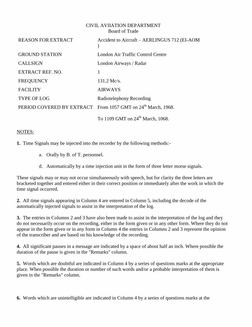
CIVIL AVIIATION DEPARTMENT
Board of Trade
REASON FOR EXTRACT Accident to Aircraft – AERLINGUS 712 (EI-AOM
)
GROUND STATION London Air Traffic Control Centre
CALLSIGN London Airways / Radar
EXTRACT REF. NO. 1
FREQUENCY 131.2 Mc/s.
FACILITY AIRWAYS
TYPE OF LOG Radiotelephony Recording
PERIOD COVERED BY EXTRACT From 1057 GMT on 24th
March, 1968.
To 1109 GMT on 24th
March, 1068.
NOTES:
1. Time Signals may be injected into the recorder by the following methods:-
a. Orally by B. of T. personnel.
d. Automatically by a time injection unit in the form of three letter morse signals.
These signals may or may not occur simultaneously with speech, but for clarity the three letters are
bracketed together and entered either in their correct position or immediately after the work in which the
time signal occurred.
2. All time signals appearing in Column 4 are entered in Column 5, including the decode of the
automatically injected signals to assist in the interpretation of the log.
3. The entries in Columns 2 and 3 have also been made to assist in the interpretation of the log and they
do not necessarily occur on the recording, either in the form given or in any other form. Where they do not
appear in the form given or in any form in Column 4 the entries in Columns 2 and 3 represent the opinion
of the transcriber and are based on his knowledge of the recording.
4. All significant pauses in a message are indicated by a space of about half an inch. Where possible the
duration of the pause is given in the "Remarks" column.
5. Words which are doubtful are indicated in Column 4 by a series of questions marks at the appropriate
place. When possible the duration or number of such words and/or a probable interpretation of them is
given in the "Remarks" column.
6. Words which are unintelligible are indicated in Column 4 by a series of questions marks at the

appropriate place. In addition, the word "unintelligible" and if possible the number or duration of the
missing words are entered in the "Remarks" column.
F.A. Abbott
…………………………………
Officer 1/c., Transcription Unit,
Southern Divisional Office, Heston
26th
March, 1968.
CERTIFIED
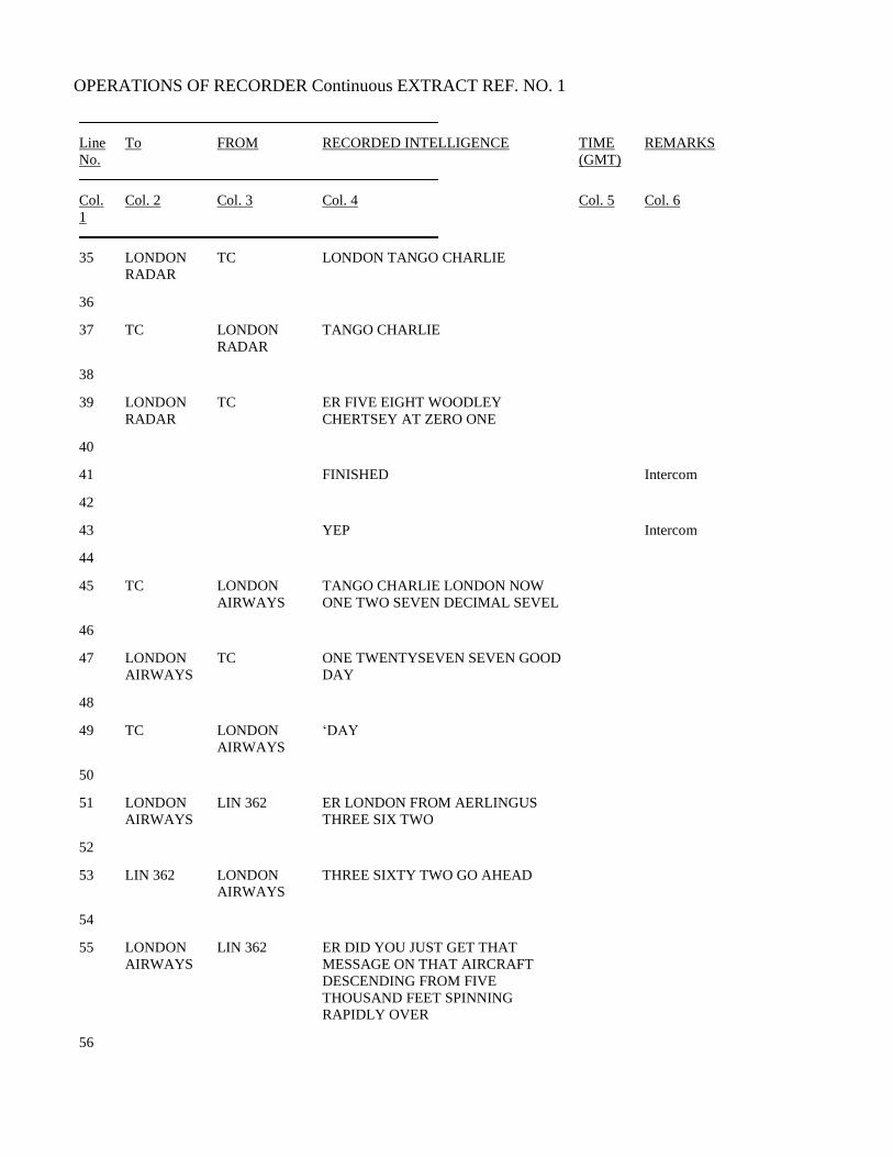
SUBJECT AIRCRAFT LIN 712 - SHEET NO. 2 OF 8 SHEETS
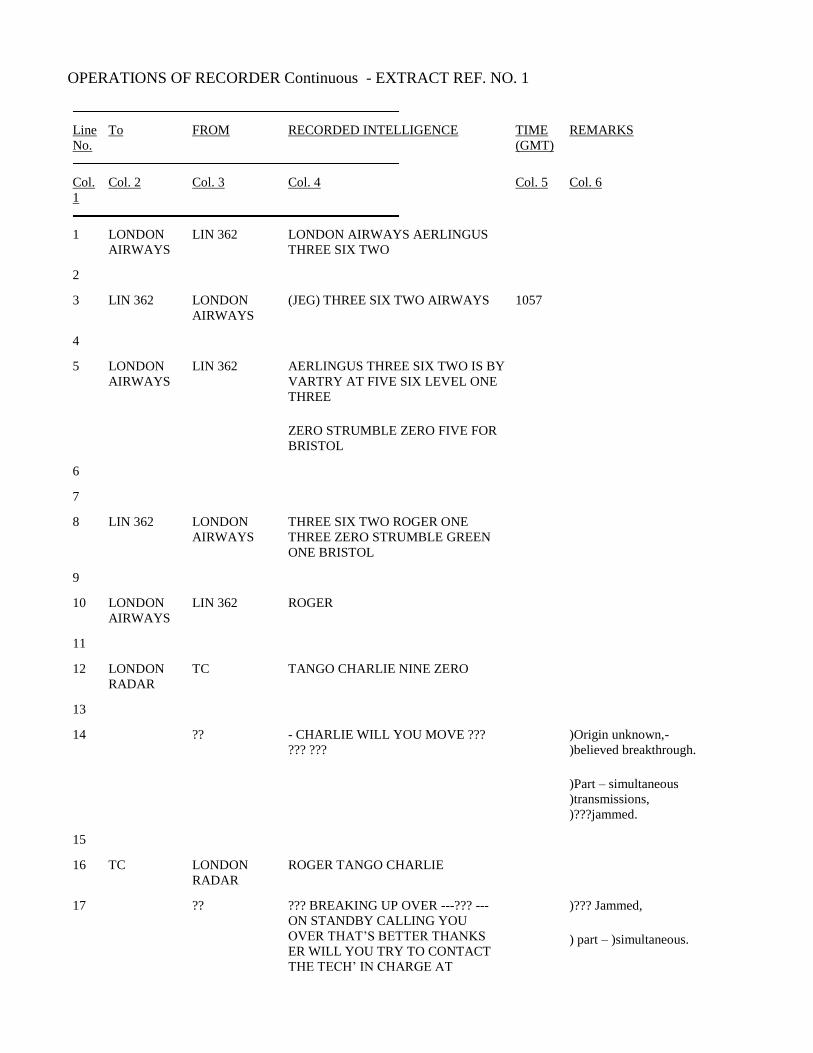
OPERATIONS OF RECORDER Continuous - EXTRACT REF. NO. 1
Line
No. To FROM RECORDED INTELLIGENCE TIME
(GMT) REMARKS
Col.
1 Col. 2 Col. 3 Col. 4 Col. 5 Col. 6
1 LONDON
AIRWAYS LIN 362 LONDON AIRWAYS AERLINGUS
THREE SIX TWO
2
3 LIN 362 LONDON
AIRWAYS (JEG) THREE SIX TWO AIRWAYS 1057
4
5 LONDON
AIRWAYS LIN 362 AERLINGUS THREE SIX TWO IS BY
VARTRY AT FIVE SIX LEVEL ONE
THREE
ZERO STRUMBLE ZERO FIVE FOR
BRISTOL
6
7
8 LIN 362 LONDON
AIRWAYS THREE SIX TWO ROGER ONE
THREE ZERO STRUMBLE GREEN
ONE BRISTOL
9
10 LONDON
AIRWAYS LIN 362 ROGER
11
12 LONDON
RADAR TC TANGO CHARLIE NINE ZERO
13
14 ?? - CHARLIE WILL YOU MOVE ???
??? ??? )Origin unknown,-
)believed breakthrough.
)Part – simultaneous
)transmissions,
)???jammed.
15
16 TC LONDON
RADAR ROGER TANGO CHARLIE
17 ?? ??? BREAKING UP OVER ---??? ---
ON STANDBY CALLING YOU
OVER THAT’S BETTER THANKS
ER WILL YOU TRY TO CONTACT
THE TECH’ IN CHARGE AT
)??? Jammed,
) part – )simultaneous.
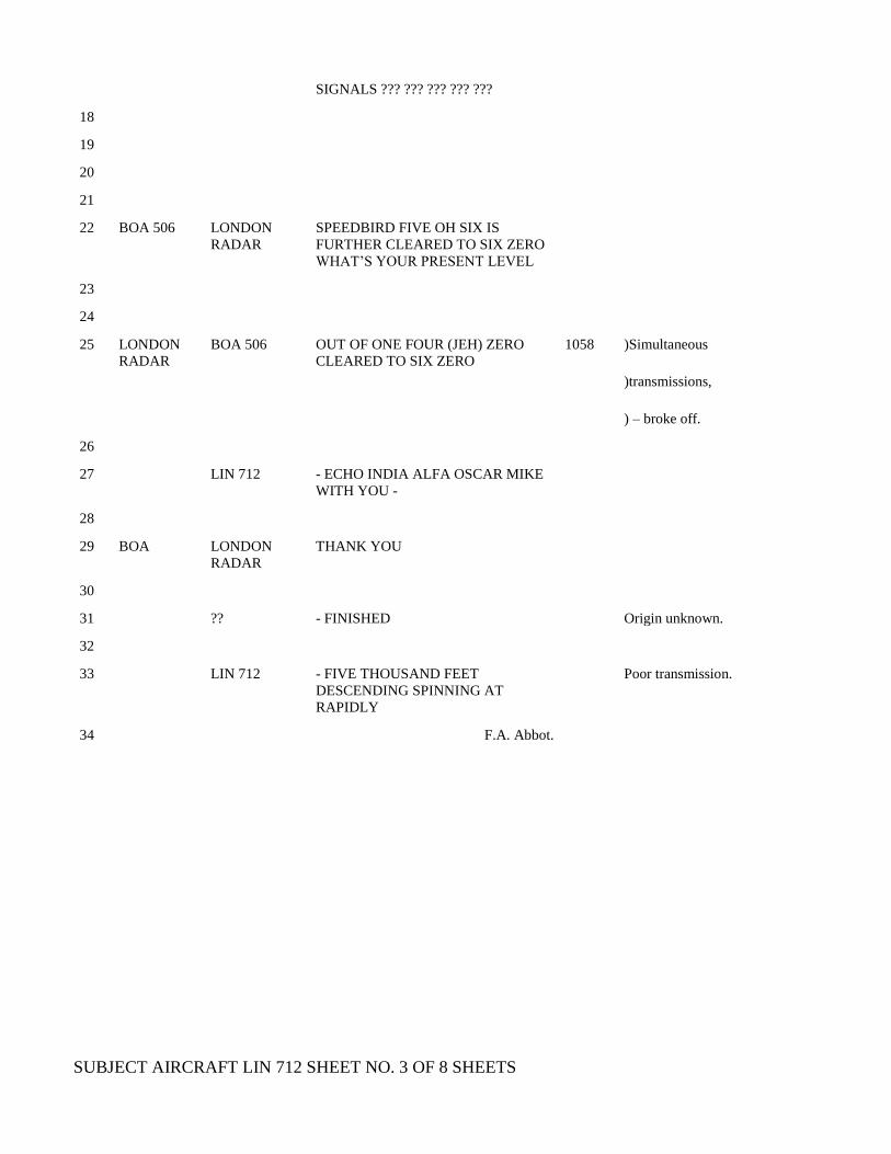
SIGNALS ??? ??? ??? ??? ???
18
19
20
21
22 BOA 506 LONDON
RADAR SPEEDBIRD FIVE OH SIX IS
FURTHER CLEARED TO SIX ZERO
WHAT’S YOUR PRESENT LEVEL
23
24
25 LONDON
RADAR BOA 506 OUT OF ONE FOUR (JEH) ZERO
CLEARED TO SIX ZERO 1058 )Simultaneous
)transmissions,
) – broke off.
26
27 LIN 712 - ECHO INDIA ALFA OSCAR MIKE
WITH YOU -
28
29 BOA LONDON
RADAR THANK YOU
30
31 ?? - FINISHED Origin unknown.
32
33 LIN 712 - FIVE THOUSAND FEET
DESCENDING SPINNING AT
RAPIDLY
Poor transmission.
34 F.A. Abbot.
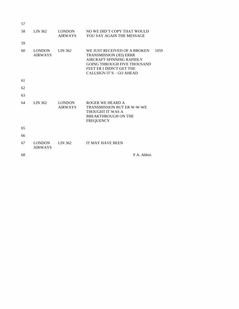
SUBJECT AIRCRAFT LIN 712 SHEET NO. 3 OF 8 SHEETS
OPERATIONS OF RECORDER Continuous EXTRACT REF. NO. 1
Line
No. To FROM RECORDED INTELLIGENCE TIME
(GMT) REMARKS
Col.
1 Col. 2 Col. 3 Col. 4 Col. 5 Col. 6
35 LONDON
RADAR TC LONDON TANGO CHARLIE
36
37 TC LONDON
RADAR TANGO CHARLIE
38
39 LONDON
RADAR TC ER FIVE EIGHT WOODLEY
CHERTSEY AT ZERO ONE
40
41 FINISHED Intercom
42
43 YEP Intercom
44
45 TC LONDON
AIRWAYS TANGO CHARLIE LONDON NOW
ONE TWO SEVEN DECIMAL SEVEL
46
47 LONDON
AIRWAYS TC ONE TWENTYSEVEN SEVEN GOOD
DAY
48
49 TC LONDON
AIRWAYS ‘DAY
50
51 LONDON
AIRWAYS LIN 362 ER LONDON FROM AERLINGUS
THREE SIX TWO
52
53 LIN 362 LONDON
AIRWAYS THREE SIXTY TWO GO AHEAD
54
55 LONDON
AIRWAYS LIN 362 ER DID YOU JUST GET THAT
MESSAGE ON THAT AIRCRAFT
DESCENDING FROM FIVE
THOUSAND FEET SPINNING
RAPIDLY OVER
56
57
58 LIN 362 LONDON
AIRWAYS NO WE DID’T COPY THAT WOULD
YOU SAY AGAIN THE MESSAGE
59
60 LONDON
AIRWAYS LIN 362 WE JUST RECEIVED OF A BROKEN
TRANSMISSION (JEI) ERRR
AIRCRAFT SPINNING RAPIDLY
GOING THROUGH FIVE THOUSAND
FEET ER I DIDN’T GET THE
CALLSIGN IT’S – GO AHEAD
1059
61
62
63
64 LIN 362 LONDON
AIRWAYS ROGER WE HEARD A
TRANSMISSION BUT ER W-W-WE
THOUGHT IT WAS A
BREAKTHROUGH ON THE
FREQUENCY
65
66
67 LONDON
AIRWAYS LIN 362 IT MAY HAVE BEEN
68 F.A. Abbot.

SUBJECT AIRCRAFT LIN 712 SHEET NO. 4 OF 8 SHEETS
OPERATIONS OF RECORDER Continuous EXTRACT REF. NO. 1
Line
No. To FROM RECORDED INTELLIGENCE TIME
(GMT) REMARKS
Col.
1 Col. 2 Col. 3 Col. 4 Col. 5 Col. 6
69 LIN 362 LONDON
AIRWAYS AERLINGUS THREE SIXTY TWO
YOU DIDN’T HAPPEN TO COPY
THE CALLSIGN DID YOU
70
71
72 LONDON
AIRWAYS LIN 362 WELL WE THOUGHT IT WAS ER
OSCAR MIKE
73 LIN 362 LONDON
AIRWAYS O K THANK YOU
74
75
76
77
LONDON
AIRWAYS BOA 506 ER FIVE OH SIX IT OUT OF ONE
ZERO THOUSAND FOR SEVEN
ZERO AND ER STILL ON THE
HEADING OF ONE SIXTY AS
GIVEN (KZZ) WE HEARD THE
LAST PART OF HIS
TRANSMISSION HE WAS
DESCENDING RAPIDLY WE
DIDN’T HEAR A CALLSIGN
1100
78
79
80 BOA 506 LONDON ER FIVE OH SIX ROGER THANK
YOU
81
82 BOA 506 LONDON
RADAR FIVE OH SIX NEXT CHECK
PASSING SEVEN ZERO CONTINUE
YOUR HEADING FOR THE
MOMENT
83
84
85 LONDON
RADAR BOA 506 FIVE OH SIX
86
87 LONDON
AIRWAYS G-HE ER LONDON GOLF HOTEL ECHO
PASSED ER STANDNY ONE
88

89 I’VE FINISHED WITH HIM Intercom
90
91 OK Intercom
92
93 LONDON
AIRWAYS G-HE ER LONDON GOLF HOTEL ECHO
PASSED WOODLEY AT ZERO ONE
ER FLIGHT LEVEL ONE FIVE ZERO
DUNSFOLD AT ZERO SEVEN
94
95
96 G-HE LONDON
AIRWAYS HOTEL ECHO LONDON ONE TWO
SEVEN DECIMAL SEVEN
97 F.A.
Abbot
98 LONDON
AIRWAYS G-HE - TWO SEVEN SEVEN ROGER
99
100 (KZA) 1101 Channel quiet.
101
102 RADAR YOU KNOW THAT BREAK
- (Intercom., - stopped
(as BOA 506 called.
103
104 LONDON
RADAR BOA 506 SPEEDBIRD FIVE OH SIX
LEVELLING AT SIX ZERO

SUBJECT AIRCRAFT LIN 712 SHEET NO. 5 OF 8 SHEETS
OPERATIONS OF RECORDER Continuous EXTRACT REF. NO. 1
Line
No. To FROM RECORDED INTELLIGENCE TIME
(GMT) REMARKS
Col.
1 Col. 2 Col. 3 Col. 4 Col. 5 Col. 6
105
106 BOA 506 LONDON
RADAR ROGER FIVE OH SIX
107
108 RADAR ON THE BREAKTHOUGH
DID ER YOU NOW THAT
TRANSMISSION DID
Intercom
109 YOU HEAR ANYTHING ON IT AT
AL ALL
110 NO ONLY THE SPINNING BIT I
DIDN’T GET ANYTHING ELSE Intercom
111
112 YOU GOT THE SPINNING DID YOU Intercom
113
114 YEAH Intercom
115
116 YEH O K THANK YOU Intercom
117
118 LONDON
RADAR TWA 705 LONDON RADAR T W A SEVEN OH
FIVE WITH YOU
119
120 TWA 705 LONDON
RADAR SEVEN OK FIVE RADAR (KZB)
FOUR THOUSAND FEET FOR THE
MOMENT ADVISE
1102
121 PASSING THREE
122
123 LONDON
RADAR TWA 705 ER WILL DO
124

125 RADAR WAS THE THE ONLY
WORD YOU HEARD SPINNING Intercom
126
127 SPINNING AND RAPIDLY ER THAT
WAS ALL Intercom
128
129 YES O K Intercom
130
131 BOA 506 LONDON
RADAR SPEEDBIRD FIVE OH SIX RADAR
WILL YOU TURN LEFT FOR
GARSTON NOW THE Q D M IS
ZERO EIGHT ZERO
132
133
134 LONDON
RADAR BOA 506 FIVE OH SIX DIRECT GARSTON
THANK YOU
135
136 LONDON
AIRWAYS LIN 362 ER LONDON AERLINGUS THREE
SIX TWO DO YOU HAVE AN
AERLINGUS SEVEN ONE TWO OR
SEVEN ONE THREE ON THE
FREQUENCY
137 F.A. Abbot
138 LIN 362 LONDON
AIRWAYS ER THERE’S A SEVEN ONE TWO
ON
139
140
141 LONDON
AIRWAYS LIN 362 ER ROGER )Continuous

SUBJECT AIRCRAFT LIN 712 SHEET NO. 6 OF 8 SHEETS
OPERATIONS OF RECORDER Continuous EXTRACT REF. NO. 1
Line
No. To FROM RECORDED INTELLIGENCE TIME
(GMT) REMARKS
Col.
1 Col. 2 Col. 3 Col. 4 Col. 5 Col. 6
142
143 LIN 712 LIN 362 SEVEN ONE TWO FROM ER THREE
SIX TWO DO YOU READ (KZC) 1103 )
) transmission.
144
145 I DON’T THINK HE’S CALLED
WE HAVEN’T GOT SEVEN ONE TWO
HAVE WE
Intercom
146 Intercom
147
148 LIN 362 LONDON
AIRWAYS ER THREE SIX TWO THERE’S A
SEVEN ONE TWO HE SHOULD
CHECK STRUMBLE AT ER ZERO
THREE AND IN POINT OF FACT HE
HASN’T CALLED US YET
149
150
151 LONDON
AIRWAYS LIN 362 ER ROGER THAT’S THE ER
CALLSIGN WE THOUGHT WE
HEARD OSCAR MIKE HE’S MOST
LIKELY TO BE SEVEN ONE TWO
152
153
154 LIN 362 LONDON
AIRWAYS ROGER YOU RECKON HIS ER OTHER
CALLSIGN IS OSCAR MIKE DO YOU
155
156 LONDON
AIRWAYS LIN 362 ER THAT’S AFFIRMATIVE
157
158 LIN 362 LONDON
AIRWAYS THANK YOU
159
160 LONDON
RADAR TWA 705 T.W.A. SEVEN OH FIVE OUT OF
THREE FOR FOUR
161

162 TWA 705 LONDON ROGER SEVEN OH FIVE CLIMB TO
EIGHT ZERO INITIALLY
163
164 LONDON
RADAR TWA 705 - K RECLEARED TO EIGHT ZERO
THANK YOU
165
166 FIVE OH SIX ABEAM WOODLEY
AND OVER Intercom
167
168 BOA 506 LONDON
AIRWAYS FIVE OH SIX ??? ??? ??? ??? (Poor modulation, -
(??? unreadable.
169
170 BOA 506 LONDON
RADAR ER FIVE OH SIX RADAR CONTINUE
ON COURSE TO GARSTON WITH
LONDON ONE ONE NINE DECIMAL
TWO
171
172
173 LONDON
RADAR BOA 506 ONE ONE NINE TWO (KZD) 1104 F.A.Abbot
174
175 YOU DIDN’T GO OUT D Intercom
176
177 LIN 712 LONDON
AIRWAYS AERLINGUS SEVEN ONE TWO ER –
AERLINGUS SEVEN ONE TWO
LONDON ONE
First part very poorly
178 THREE ONE DECIMAL TWO YOU ON
THE FREQUENCY modulated.
179
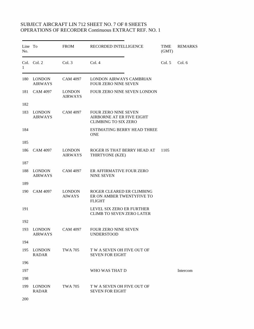
SUBJECT AIRCRAFT LIN 712 SHEET NO. 7 OF 8 SHEETS
OPERATIONS OF RECORDER Continuous EXTRACT REF. NO. 1
Line
No. To FROM RECORDED INTELLIGENCE TIME
(GMT) REMARKS
Col.
1 Col. 2 Col. 3 Col. 4 Col. 5 Col. 6
180 LONDON
AIRWAYS CAM 4097 LONDON AIRWAYS CAMBRIAN
FOUR ZERO NINE SEVEN
181 CAM 4097 LONDON
AIRWAYS FOUR ZERO NINE SEVEN LONDON
182
183 LONDON
AIRWAYS CAM 4097 FOUR ZERO NINE SEVEN
AIRBORNE AT ER FIVE EIGHT
CLIMBING TO SIX ZERO
184 ESTIMATING BERRY HEAD THREE
ONE
185
186 CAM 4097 LONDON
AIRWAYS ROGER IS THAT BERRY HEAD AT
THIRTYONE (KZE) 1105
187
188 LONDON
AIRWAYS CAM 4097 ER AFFIRMATIVE FOUR ZERO
NINE SEVEN
189
190 CAM 4097 LONDON
AIWAYS ROGER CLEARED ER CLIMBING
ER ON AMBER TWENTYFIVE TO
FLIGHT
191 LEVEL SIX ZERO ER FURTHER
CLIMB TO SEVEN ZERO LATER
192
193 LONDON
AIRWAYS CAM 4097 FOUR ZERO NINE SEVEN
UNDERSTOOD
194
195 LONDON
RADAR TWA 705 T W A SEVEN OH FIVE OUT OF
SEVEN FOR EIGHT
196
197 WHO WAS THAT D Intercom
198
199 LONDON
RADAR TWA 705 T W A SEVEN OH FIVE OUT OF
SEVEN FOR EIGHT
200

201 TWA 705 LONDON
RADAR ROGER SEVEN OH FIVE
CONTINUE THE CLIMB TO FLIGHT
LEVEL TWO EIGHT
F.A.Abbot
202 ZERO NOW
203
204 LONDON
RADAR TWA 705 O K THANK YOU UNRESTRICTED
NOW TO TWO EIGHT OH
205
206 (KZF) 1106 Channel Quiet
207
208 IF YOU HAVEN’T DONE IT
ALREADY YOU MIGHT SUGGEST
TO AERLINGUS THE
209 COMPANY FREQUENCY SEE IF
THEY’VE GOT ANY TRACE OF
THIS AIRCRAFT
Intercom.
210
211 STANDBY RADAR PLEASE Intercom
212
213 LONDON
AIRWAYS LIN 362 LONDON AIRWAYS AERLINGUS
THREE SIX TWO BY STRUMBLE
ZERO SIX LEVEL
214 ONE THREE ZERO AMMANFORD
ONE (KZG) FIVE BRECON NEXT 1107
214
215

SUBJECT AIRCRAFT LIN 712 SHEET NO. 8 OF 8 SHEETS
OPERATIONS OF RECORDER Continuous EXTRACT REF. NO. 1
Line
No. To FROM RECORDED INTELLIGENCE TIME
(GMT) REMARKS
Col.
1 Col. 2 Col. 3 Col. 4 Col. 5 Col. 6
216 LIN 712 LONDON
AIRWAYS AERLINGUS SEVEN ONE TWO THIS
IS LONDON AIRWAYS D’YOU READ
217 LIN 362 LONDON
AIRWAYS AERLINGUS ER THREE SIX TWO
WE’VE HAD NO CONTACT WITH
AERLINGUS
218 SEVEN ONE TWO YOU TRY AND
GIVE HIM A CALL SHANNON HAVE
NO CONTACT
219 AT THE MOMENT THAT CALL YOU
HEARD EARLIER COULD BE OF
SOME
220 IMPORTANCE OVER
221
222 LONDON
AIRWAYS LIN 362 ER THAT’S AFFIRMATIVE ER AS
FAR AS I ER ER ER IT SEEMED TO
BE VERY
223 BROKEN ERRR WE THINK IT WAS
ECHO INDIA ALFA OSCAR MIKE ER
THE
224 MESSAGE WAS HE WAS
DESCENDING RAPIDLY THROUGH
FIVE THOUSAND FEET
225 SPINNING
226
227 LIN 362 LONDON
AIRWAYS THANK YOU VERY MUCH WE’VE
TAKEN ALL THE ACTION WE CAN
AT THE MOMENT
228
229 LONDON
AIRWAYS LIN 362 ROGER
230
231 LONDON
AIRWAYS LIN 362 ER THREE (KZH) SIX TWO CHECKED
STRUMBLE ZERO SIX LEVEL ONE
THREE
1108
232 ZERO AMMANFORD ONE FIVE
233

234 LIN 362 LONDON
AIRWAYS ER THREE SIXTYTWO ROGER
235
236 LONDON
RADAR TWA 705 ER T W A SEVEN OH FIVE
WOODLEY AT ER ZERO SIX
CLIMBING WE’RE
237 ESTIMATING LYNEHAM AT
TWELVE BRECON ER MAKE THAT
FOURTEEN FOR
238 LYNEHAM
239
240 TWA 705 LONDON
RADAR SEVEN OH FIVE
241
242 (KZI) 1109 Channel quiet.
I certify that this extract, consisting of 8 sheets, each of which bears my signature, from the
Radiotelephony Recording Log kept at London A.T.C.C. by the Board of Trade has been prepared
under my direction and has been examined and checked by me; that Column 4 thereof is a
transcription of the recording believed by me to be accurate in all respects; and that column 5 contains
a correct interpretation of the time signals appearing in code in Column 4.
F.A. Abbot
………………………………
26th March, 1968
………………………………..
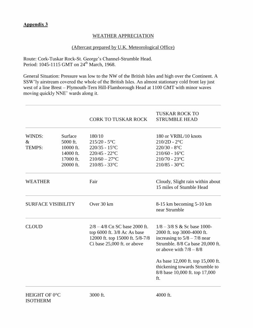
Appendix 3
WEATHER APPRECIATION
(Aftercast prepared by U.K. Meteorological Office)
Route: Cork-Tuskar Rock-St. George’s Channel-Strumble Head.
Period: 1045-1115 GMT on 24th
March, 1968.
General Situation: Pressure was low to the NW of the British Isles and high over the Continent. A
SSW’ly airstream covered the whole of the British Isles. An almost stationary cold front lay just
west of a line Brest – Plymouth-Tern Hill-Flamborough Head at 1100 GMT with minor waves
moving quickly NNE’ wards along it.
CORK TO TUSKAR ROCK
TUSKAR ROCK TO
STRUMBLE HEAD
WINDS:
&
TEMPS:
Surface
5000 ft.
10000 ft.
14000 ft.
17000 ft.
20000 ft.
180/10
215/20 - 5°C
220/35 - 15°C
220/45 - 22°C
210/60 – 27°C
210/85 - 33°C
180 or VRBL/10 knots
210/2D - 2°C
220/30 - 8°C
210/60 - 16°C
210/70 - 23°C
210/85 - 30°C
WEATHER Fair Cloudy, Slight rain within about
15 miles of Stumble Head
SURFACE VISIBILITY Over 30 km 8-15 km becoming 5-10 km
near Strumble
CLOUD 2/8 – 4/8 Cn SC base 2000 ft.
top 6000 ft. 3/8 Ac As base
12000 ft. top 15000 ft. 5/8-7/8
Ci base 25,000 ft. or above
1/8 – 3/8 S & Sc base 1000-
2000 ft. top 3000-4000 ft.
increasing to 5/8 – 7/8 near
Strumble. 8/8 Ca base 20,000 ft.
or above with 7/8 – 8/8
As base 12,000 ft. top 15,000 ft.
thickening towards Strumble to
8/8 base 10,000 ft. top 17,000
ft.
HEIGHT OF 0°C
ISOTHERM
3000 ft. 4000 ft.
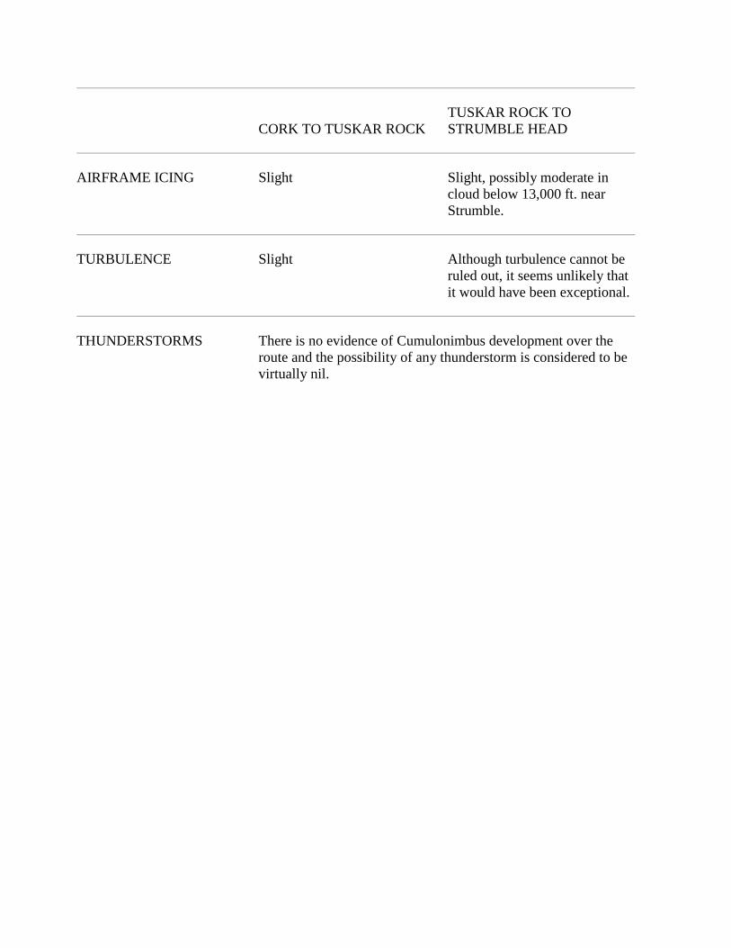
CORK TO TUSKAR ROCK
TUSKAR ROCK TO
STRUMBLE HEAD
AIRFRAME ICING Slight Slight, possibly moderate in
cloud below 13,000 ft. near
Strumble.
TURBULENCE Slight Although turbulence cannot be
ruled out, it seems unlikely that
it would have been exceptional.
THUNDERSTORMS There is no evidence of Cumulonimbus development over the
route and the possibility of any thunderstorm is considered to be
virtually nil.
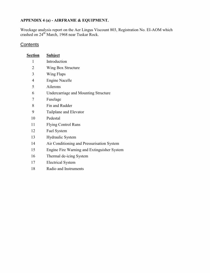
APPENDIX 4 (a) - AIRFRAME & EQUIPMENT.
Wreckage analysis report on the Aer Lingus Viscount 803, Registration No. EI-AOM which
crashed on 24th
March, 1968 near Tuskar Rock.
Contents
Section Subject
1 Introduction
2 Wing Box Structure
3 Wing Flaps
4 Engine Nacelle
5 Ailerons
6 Undercarriage and Mounting Structure
7 Fuselage
8 Fin and Rudder
9 Tailplane and Elevator
10 Pedestal
11 Flying Control Runs
12 Fuel System
13 Hydraulic System
14 Air Conditioning and Pressurisation System
15 Engine Fire Warning and Extinguisher System
16 Thermal de-icing System
17 Electrical System
18 Radio and Instruments

Accident to Viscount 803 Aircraft EI-AOM
near Tuskar Rock, Co. Wexford on 24th March, 1968 Appendix 4a - Page 1 of 50
Section 1 – Introduction
The Wreckage analysis was carried out in No. 3 Hangar at Casement Aerodrome and facilities were
provided for washing down the wreckage and treating where necessary to inhibit corrosion.
The majority of the floating debris was recovered during the period 25th to 30th March 1968. This consisted
of:- the port main wheels attached to the inner cylinder; pieces of the centre aisle balsa core floor; some seat
cushions; carpeting; a few life jackets; personal effects and other items from the cabin interior.
It was almost three months after the accident before the main wreckage site was pin-pointed by the recovery
of the fuselage structure over the rear entry doors, and in the ensuing fifteen months the remainder of the
wreckage was recovered at various times when the weather and tides were suitable.
The damage caused by immersion in the sea was readily apparent and did not in general hamper the
investigation. It consisted of corrosion, marine encrustation, and some polishing and scoring on the lighter
pieces. The extent of the damage varied widely depending on the material, protective treatment and time in
the sea. With the exception of a few isolated areas the general airframe structure was little effected but
corrosion was very evident on the passenger seat rails and all of the magnesium components (i.e. engine
casings, some control run items, wheel hubs and portions of the passenger seats.) This varied from deep
pitting and holing to complete disintegration.
An initial survey of the weckage did not produce any indication as to the probable cause of the accident and
to assist the investigation it was decided to reconstruct the airframe.
Identification of the weckage was time consuming. Some of the pieces were easily placed because of the
local structural variations at doors, windows, fairings, etc. and others by the external paint scheme. However,
in a number of cases it was necessary to make on the spot comparisons with similar aircraft. A large number
of the smaller pieces could not be accurately placed and were only identified as belonging either to the wings
or fuselage or some other component.
The wings including flaps, ailerons, nacelles and undercarriage were reconstructed as completely as
possible. The fuselage was severly fragmented but because of the small amount recovered it was possible to
carry out the investigation without recourse to a three-dimensional build up.
The items recovered in the tail area were the upper two-thirds of the fin and rudder, the rudder torque tube,
portion of the tabs from the rudder and elevators and about three square feet of rudder skin. The tailplanes,
elevators and the fuselage structure in the tailcone area were not recovered.
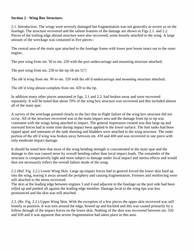
Section 2 - Wing Box Structure.
2.1. Introduction. The wings were severely damaged but fragmentation was not generally as severe as on the
fuselage. The structure recovered and the salient features of the damage are shown in Figs 2.1. and 2.2.
Pieces of the trailing edge shroud structure were also recovered, some loosely attached to the wing. A large
amount of the wreckage was contained in five pieces:-
The central area of the main spar attached to the fuselage frame with lower port boom intact out to the outer
engine;
The port wing from stn. 50 to stn. 230 with the port undercarriage and mounting structure attached;
The port wing from stn. 230 to the tip rib stn 517;
The stb’d wing from stn. 96 to stn. 320 with the stb’d undercarriage and mounting structure attached;
The stb’d wing almost complete from stn. 420 to the tip.
In addition many other pieces annotated in figs. 2.1 and 2.2. had broken away and were recovered
separately. It will be noted that about 70% of the wing box structure was recovered and this included almost
all of the main spar.
A survey of the wreckage pointed clearly to the fact that in-flight failure of the wing box structure did not
occur. All of the structure recovered was in the main impact area and the damage from tip to tip was
consistent with the wings being attached to impact. The general impression created was that large up and
rearward forces had at some time during impact been applied to the lower surface. The fuel tanks had been
ripped apart and remnants of the tank sheeting and bladders were attached to the wing structure. The outer
portion of the stb’d wing was broken away between stn. 430 and 460 and was recovered in one piece with
only moderate impact damage.
It should be noted here that most of the wing bending strength is concentrated in the main spar and the
damage to this was caused more by overall bending rather than local impact loads. The remainder of the
structure is comparatively light and more subject to damage under local impact and inertia effects and would
thus not necessarily reflect the overall failure mode of the wing.
2.2 (Ref. Fig. 2.2.) Lower Wing Skin. Large up-impact forces had in general forced the lower skin hard up
into the wing, tearing it away around the periphery and causing fragmentation. Formers and reinforcing were
still attached to the items recovered.
The skin at the leading edge between engines 3 and 4 and adjacent to the fuselage on the port side had been
rolled up and pushed aft against the leading edge member. Damage local to the wing tips was less
pronounced and the skin was still attached.
2.3. (Re. Fig. 2.2.) Upper Wing Skin. With the exception of a few pieces the upper skin recovered was still
loosely in position. It was torn around the edge, bowed up and buckled and this was caused primarily by a
follow through of the impact forces on the lower skin. Nothing of the skin was recovered between stn. 320
and 430 and it was apparent that severe fragmentation had taken place in this area.
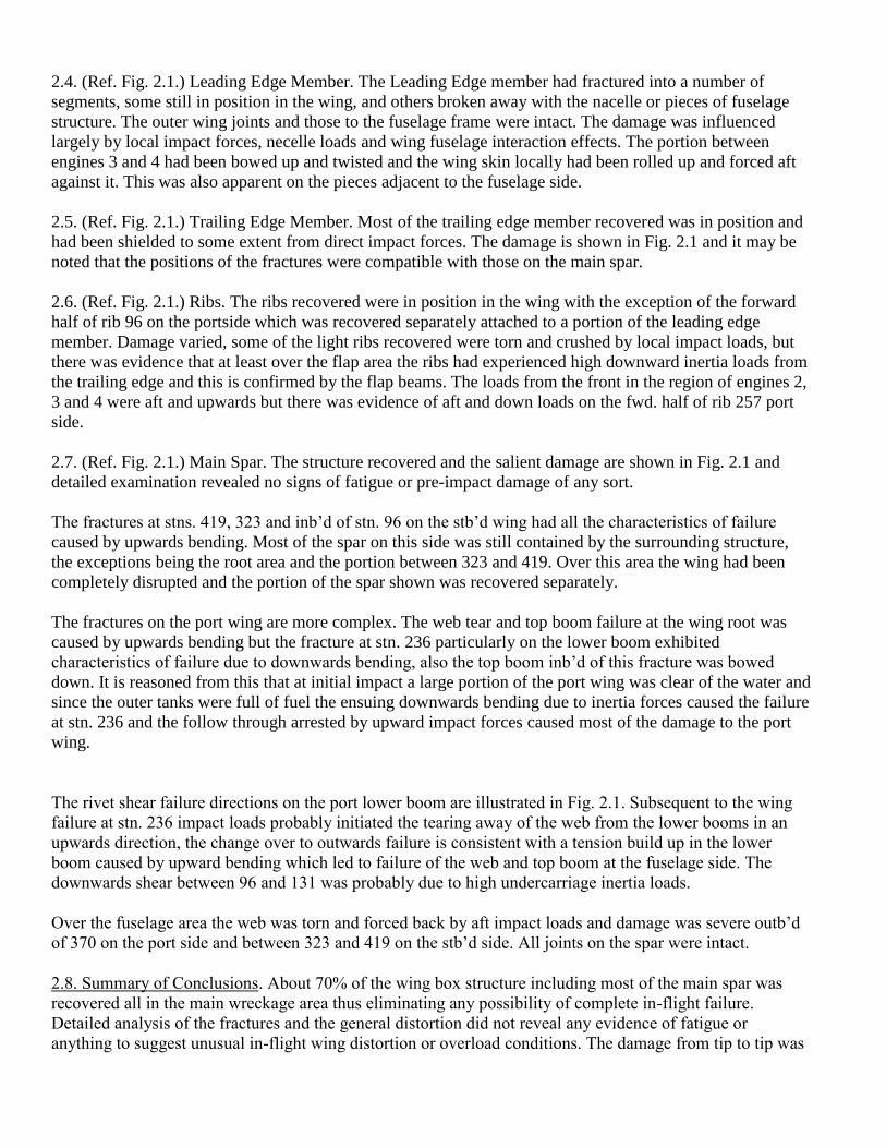
2.4. (Ref. Fig. 2.1.) Leading Edge Member. The Leading Edge member had fractured into a number of
segments, some still in position in the wing, and others broken away with the nacelle or pieces of fuselage
structure. The outer wing joints and those to the fuselage frame were intact. The damage was influenced
largely by local impact forces, necelle loads and wing fuselage interaction effects. The portion between
engines 3 and 4 had been bowed up and twisted and the wing skin locally had been rolled up and forced aft
against it. This was also apparent on the pieces adjacent to the fuselage side.
2.5. (Ref. Fig. 2.1.) Trailing Edge Member. Most of the trailing edge member recovered was in position and
had been shielded to some extent from direct impact forces. The damage is shown in Fig. 2.1 and it may be
noted that the positions of the fractures were compatible with those on the main spar.
2.6. (Ref. Fig. 2.1.) Ribs. The ribs recovered were in position in the wing with the exception of the forward
half of rib 96 on the portside which was recovered separately attached to a portion of the leading edge
member. Damage varied, some of the light ribs recovered were torn and crushed by local impact loads, but
there was evidence that at least over the flap area the ribs had experienced high downward inertia loads from
the trailing edge and this is confirmed by the flap beams. The loads from the front in the region of engines 2,
3 and 4 were aft and upwards but there was evidence of aft and down loads on the fwd. half of rib 257 port
side.
2.7. (Ref. Fig. 2.1.) Main Spar. The structure recovered and the salient damage are shown in Fig. 2.1 and
detailed examination revealed no signs of fatigue or pre-impact damage of any sort.
The fractures at stns. 419, 323 and inb’d of stn. 96 on the stb’d wing had all the characteristics of failure
caused by upwards bending. Most of the spar on this side was still contained by the surrounding structure,
the exceptions being the root area and the portion between 323 and 419. Over this area the wing had been
completely disrupted and the portion of the spar shown was recovered separately.
The fractures on the port wing are more complex. The web tear and top boom failure at the wing root was
caused by upwards bending but the fracture at stn. 236 particularly on the lower boom exhibited
characteristics of failure due to downwards bending, also the top boom inb’d of this fracture was bowed
down. It is reasoned from this that at initial impact a large portion of the port wing was clear of the water and
since the outer tanks were full of fuel the ensuing downwards bending due to inertia forces caused the failure
at stn. 236 and the follow through arrested by upward impact forces caused most of the damage to the port
wing.
The rivet shear failure directions on the port lower boom are illustrated in Fig. 2.1. Subsequent to the wing
failure at stn. 236 impact loads probably initiated the tearing away of the web from the lower booms in an
upwards direction, the change over to outwards failure is consistent with a tension build up in the lower
boom caused by upward bending which led to failure of the web and top boom at the fuselage side. The
downwards shear between 96 and 131 was probably due to high undercarriage inertia loads.
Over the fuselage area the web was torn and forced back by aft impact loads and damage was severe outb’d
of 370 on the port side and between 323 and 419 on the stb’d side. All joints on the spar were intact.
2.8. Summary of Conclusions. About 70% of the wing box structure including most of the main spar was
recovered all in the main wreckage area thus eliminating any possibility of complete in-flight failure.
Detailed analysis of the fractures and the general distortion did not reveal any evidence of fatigue or
anything to suggest unusual in-flight wing distortion or overload conditions. The damage from tip to tip was
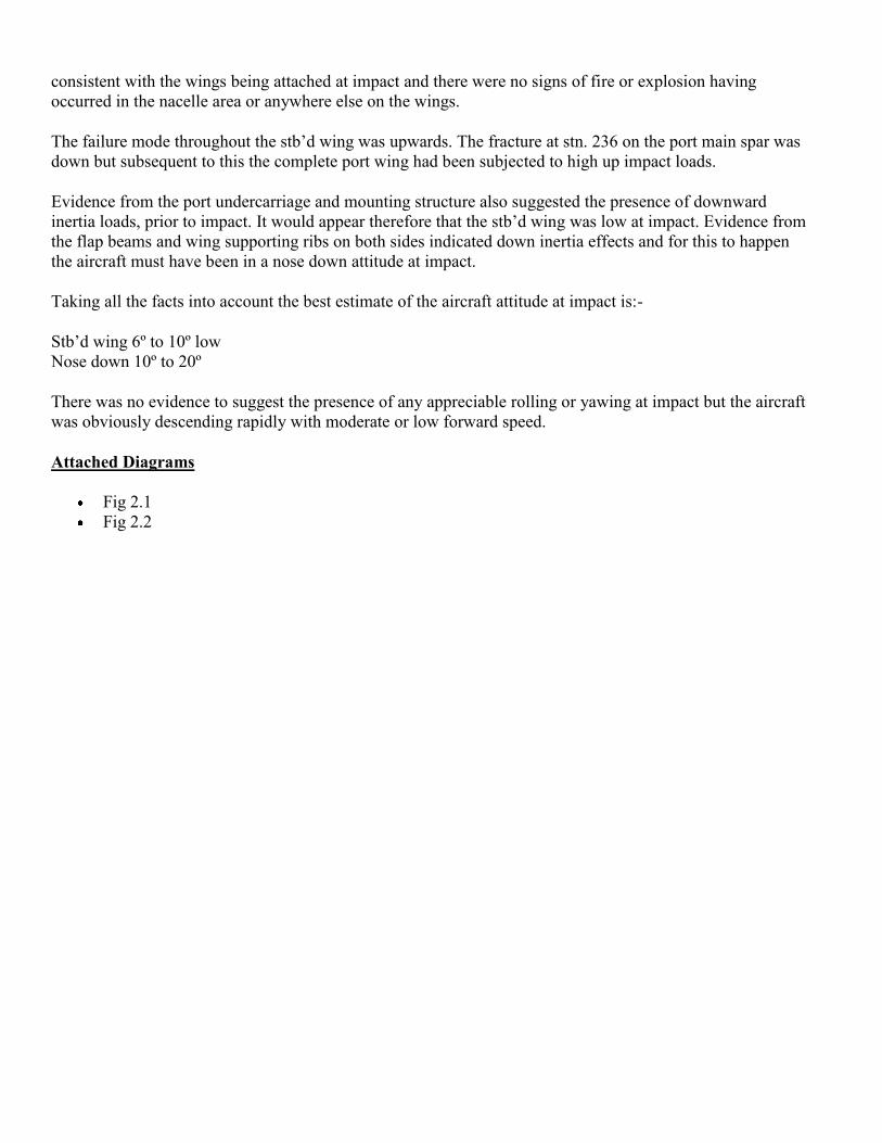
consistent with the wings being attached at impact and there were no signs of fire or explosion having
occurred in the nacelle area or anywhere else on the wings.
The failure mode throughout the stb’d wing was upwards. The fracture at stn. 236 on the port main spar was
down but subsequent to this the complete port wing had been subjected to high up impact loads.
Evidence from the port undercarriage and mounting structure also suggested the presence of downward
inertia loads, prior to impact. It would appear therefore that the stb’d wing was low at impact. Evidence from
the flap beams and wing supporting ribs on both sides indicated down inertia effects and for this to happen
the aircraft must have been in a nose down attitude at impact.
Taking all the facts into account the best estimate of the aircraft attitude at impact is:-
Stb’d wing 6º to 10º low
Nose down 10º to 20º
There was no evidence to suggest the presence of any appreciable rolling or yawing at impact but the aircraft
was obviously descending rapidly with moderate or low forward speed.
Attached Diagrams
Fig 2.1
Fig 2.2
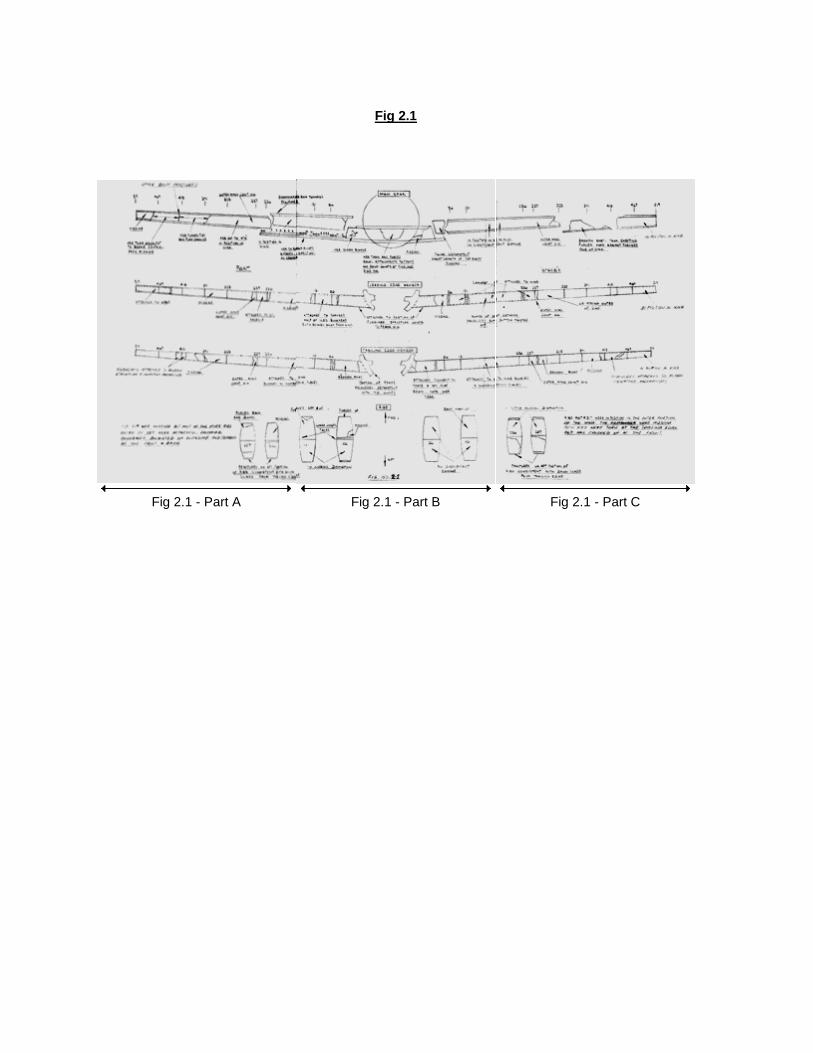
Fig 2.1
Fig 2.1 - Part A Fig 2.1 - Part B Fig 2.1 - Part C

Fig 2.1 - Part A
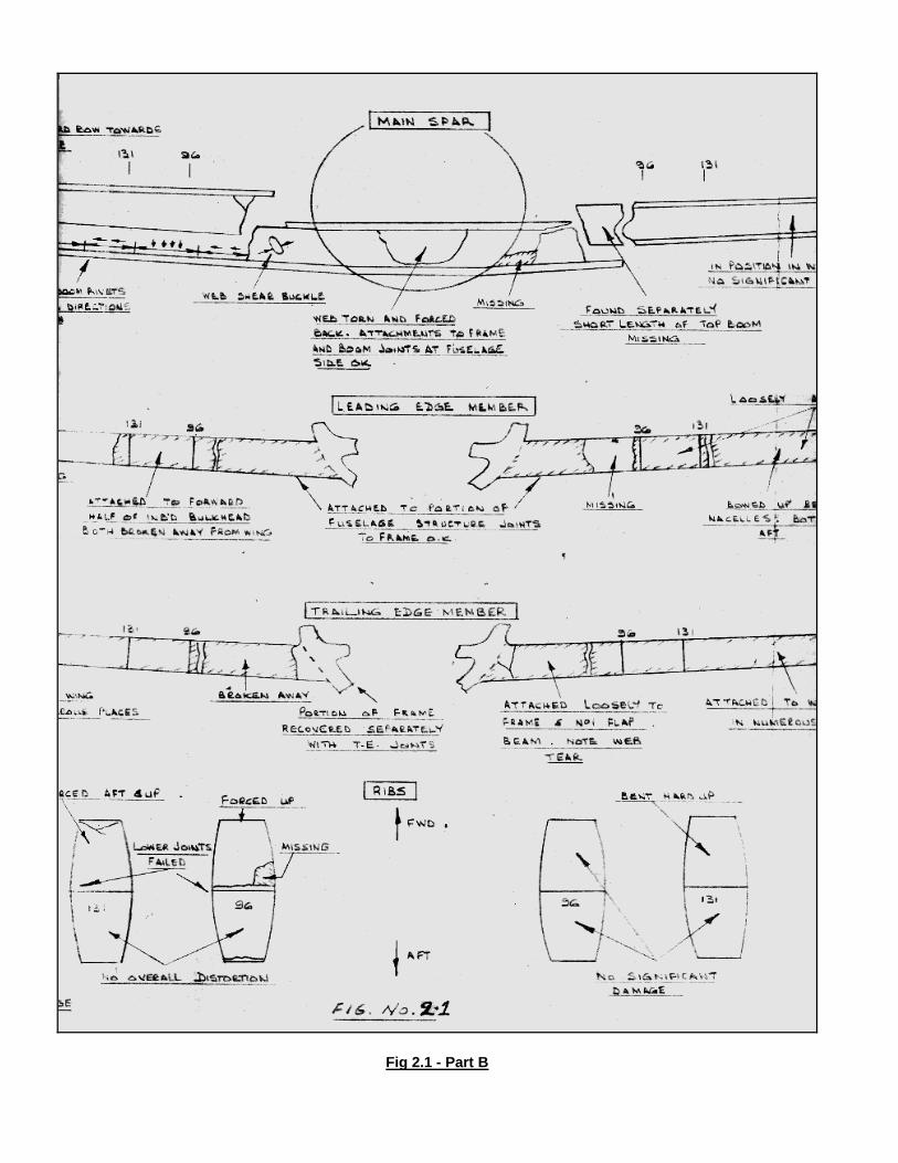
Fig 2.1 - Part B
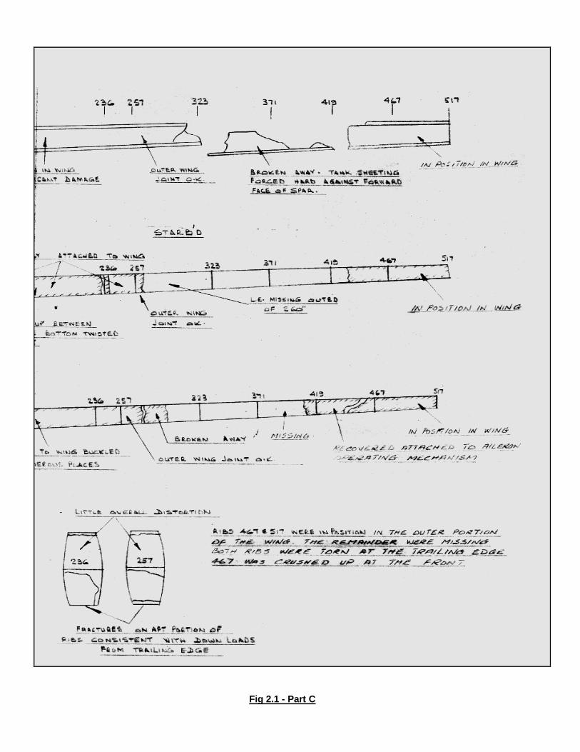
Fig 2.1 - Part C
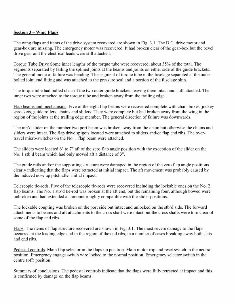
Section 3 – Wing Flaps
The wing flaps and items of the drive system recovered are shown in Fig. 3.1. The D.C. drive motor and
gear-box are missing. The emergency motor was recovered. It had broken clear of the gear-box but the bevel
drive gear and the electrical leads were still attached.
Torque Tube Drive Some inner lengths of the torque tube were recovered, about 35% of the total. The
segments separated by failing the splined joints at the beams and joints on either side of the guide brackets.
The general mode of failure was bending. The segment of torque tube in the fuselage separated at the outer
bolted joint end fitting and was attached to the pressure seal and a portion of the fuselage skin.
The torque tube had pulled clear of the two outer guide brackets leaving them intact and still attached. The
inner two were attached to the torque tube and broken away from the trailing edge.
Flap beams and mechanisms. Five of the eight flap beams were recovered complete with chain boxes, jockey
sprockets, guide rollers, chains and sliders. They were complete but had broken away from the wing in the
region of the joints at the trailing edge member. The general direction of failure was downwards.
The inb’d slider on the number two port beam was broken away from the chain but otherwise the chains and
sliders were intact. The flap drive spigots located were attached to sliders and/or flap end ribs. The over-
travel micro-switches on the No. 1 flap beam were attached.
The sliders were located 6" to 7" aft of the zero flap angle position with the exception of the slider on the
No. 1 stb’d beam which had only moved aft a distance of 3".
The guide rails and/or the supporting structure were damaged in the region of the zero flap angle positions
clearly indicating that the flaps were retracted at initial impact. The aft movement was probably caused by
the induced nose up pitch after initial impact.
Telescopic tie-rods. Five of the telescopic tie-rods were recovered including the lockable ones on the No. 2
flap beams. The No. 1 stb’d tie-rod was broken at the aft end, but the remaining four, although bowed were
unbroken and had extended an amount roughly compatible with the slider positions.
The lockable coupling was broken on the port side but intact and unlocked on the stb’d side. The forward
attachments to beams and aft attachments to the cross shaft were intact but the cross shafts were torn clear of
some of the flap end ribs.
Flaps. The items of flap structure recovered are shown in Fig. 3.1. The most severe damage to the flaps
occurred at the leading edge and in the region of the end ribs, in a number of cases breaking away both slats
and end ribs.
Pedestal controls. Main flap selector in the flaps up position. Main motor trip and reset switch in the neutral
position. Emergency engage switch wire locked to the normal position. Emergency selector switch in the
centre (off) position.
Summary of conclusions. The pedestal controls indicate that the flaps were fully retracted at impact and this
is confirmed by damage on the flap beams.

Examination of the wreckage revealed no signs of fatigue, overload, or malfunction having occurred in flight
but there is sufficient evidence to say that the system was intact at impact.
The flap beam joints at the trailing edge member were disrupted by loads in a downwards direction caused
by inertia effects on the flaps and flap beams at impact. It is probable that the aircraft struck in a nose down
attitude with the flaps clear of the water.
Attached Diagrams
Fig 3.1

Wing Flaps - Fig 3.1

Section 4 Engine Nacelle.
A large proportion of the four nacelles was recovered. These were pieced together in their relative positions
on the airframe mock-up and studied. Refer to Figs. 4.1., 4.2., 4.3. which shows the tabular structure
recovered and the damage.
Nacelle No. 1. The engine had broken away from the nacelle by failing the bolts attaching the mounting
brackets to the casing. The nacelle structure had parted from the wing and was recovered in one piece
comprising: the tubular structure shown in Figs. 4.1 and 4.2., the firewall mounted in position with exhaust
assembly, a portion of the wing L.E. member attached to the top tubes, most of the top and some of the side
nacelle panels. The jet pipe and shroud, frame and tube joints below the wing L.E. were missing.
The top of the nacelle was in good condition, but the bottom inb’d side of the firewall and associated tubular
members were severely damaged. The actual impact loads were essentially upwards and aft and it was noted
that the damage was more severe at the lower inbound corner.
Nacelle No. 2. The nacelle structure had completely separated between the firewall and the wing L.E. and
was recovered in two pieces. The forward portion consisting of: firewall, exhaust assembly shroud, tubular
structure forward and aft of the firewall, and small pieces of macelle skinning were loosely attached to the
engine. A number of bolts attaching the engine mounting brackets to the casing were broken. The aft portion
of the nacelle which included some tubular structure, jet pipe and shroud and the frame at the L.E. was
attached to a large portion of the local wing structure (L.E. member and inboard forward wing rib).
It was obvious that the nacelles had been subjected to large upwards and some aft impact loads. The firewall
was pushed back at the lower end, the jet pipe was crushed flat and the frame at the L.E. had been forced
backwards and upwards breaking clear of the tubes at the outer joint.
Nacelle No. 3. This nacelle had also separated between the firewall and wing L.E. The frame at the L.E. and
the jet pipe and shroud were missing and bits of the tubular structure were attached to the large portion of
stb’d wing recovered. The forward portion of the nacelle was recovered loosely attached to the engine and
comprised the firewall mounted in position with exhaust assembly, tubular structure f’wd and aft of the
firewall and small pieces of nacelle skinning. Some pieces of the tubular structure were recovered separately.
The firewall was badly damaged by aft impact loads and it was apparent that the bottom of the nacelle had
been subjected to large upward and aft impact loads. Damage was more pronounced at the outb’d side.
Nacelle No. 4. This nacelle was more severely damaged than the outb’d one on the port wing and again the
engine had broken away by failing the bolts attaching the mounting brackets to the casing. The forward part
of the nacelle was recovered broken away from the wing and includes the firewall mounted in position with
exhaust assembly shroud, some tubular structure forward and aft of the firewall and pieces of the nacelle
skinning. The lower tubes on the outb’d side were recovered separately with a portion of the L.E. frame, and
bits of the tubular structure were still attached to the wing. The portion of the nacelle on the wing was
distorted down and out. The bottom of the firewall was bent aft and badly damaged, more severely on the
outb’d side and the nacelle had been subjected to up and aft impact loads.
Summary of Conclusions
The loads at impact would be: rotational, aft and up impact loads on the propeller blades and engines, inertia
and impact loads applied directly to the nacelles, and interaction loads between the wings and nacelle.
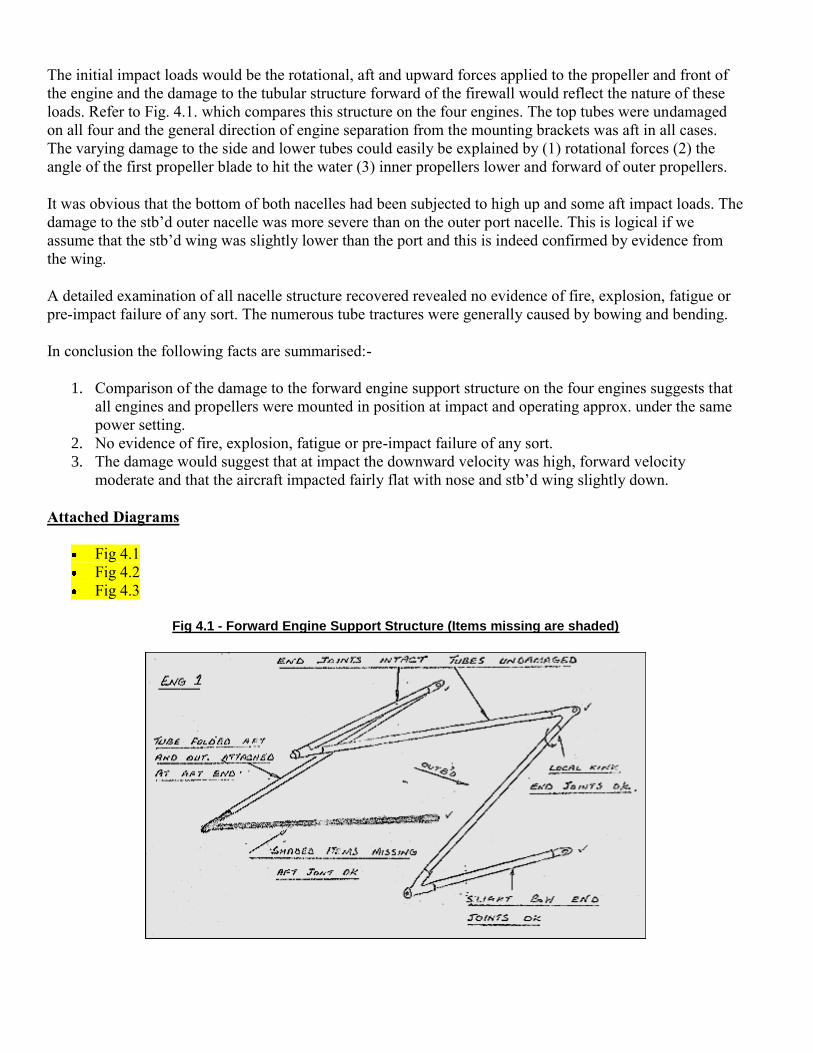
The initial impact loads would be the rotational, aft and upward forces applied to the propeller and front of
the engine and the damage to the tubular structure forward of the firewall would reflect the nature of these
loads. Refer to Fig. 4.1. which compares this structure on the four engines. The top tubes were undamaged
on all four and the general direction of engine separation from the mounting brackets was aft in all cases.
The varying damage to the side and lower tubes could easily be explained by (1) rotational forces (2) the
angle of the first propeller blade to hit the water (3) inner propellers lower and forward of outer propellers.
It was obvious that the bottom of both nacelles had been subjected to high up and some aft impact loads. The
damage to the stb’d outer nacelle was more severe than on the outer port nacelle. This is logical if we
assume that the stb’d wing was slightly lower than the port and this is indeed confirmed by evidence from
the wing.
A detailed examination of all nacelle structure recovered revealed no evidence of fire, explosion, fatigue or
pre-impact failure of any sort. The numerous tube tractures were generally caused by bowing and bending.
In conclusion the following facts are summarised:-
1. Comparison of the damage to the forward engine support structure on the four engines suggests that
all engines and propellers were mounted in position at impact and operating approx. under the same
power setting.
2. No evidence of fire, explosion, fatigue or pre-impact failure of any sort.
3. The damage would suggest that at impact the downward velocity was high, forward velocity
moderate and that the aircraft impacted fairly flat with nose and stb’d wing slightly down.
Attached Diagrams
Fig 4.1
Fig 4.2
Fig 4.3
Fig 4.1 - Forward Engine Support Structure (Items missing are shaded)
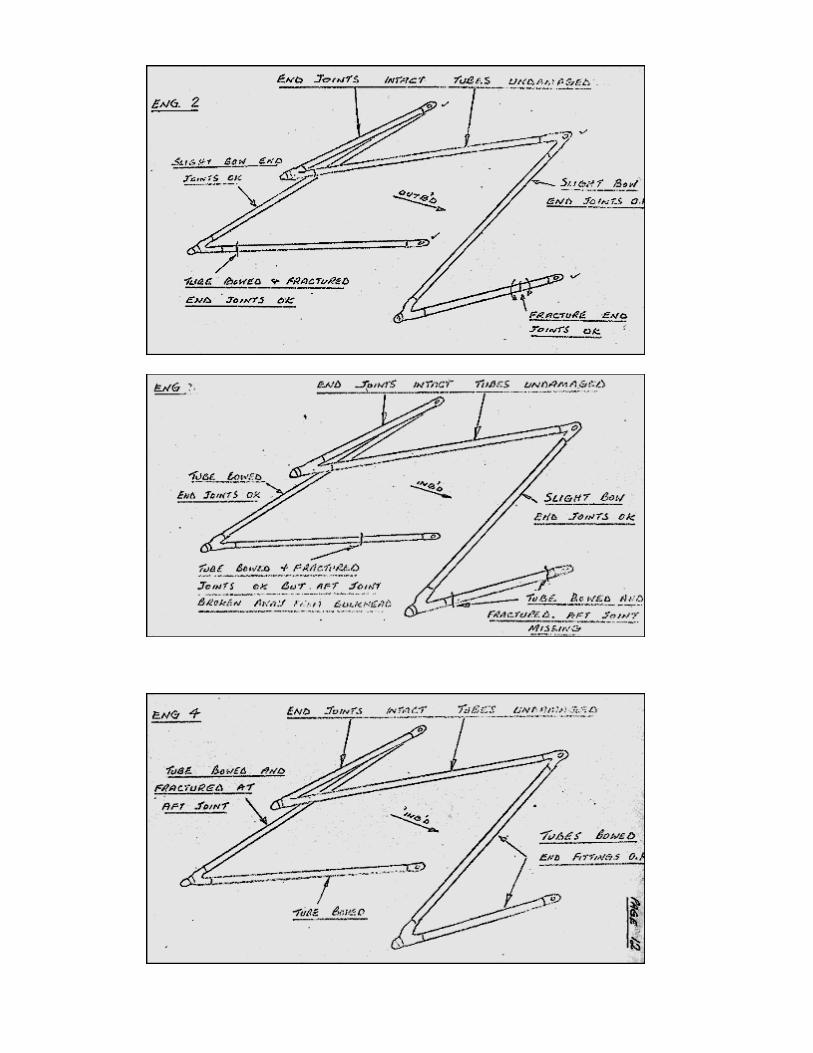

Fig 4.2 - Tubular Structure Outer Nacelles (Items missing are shaded) - F = Fracture
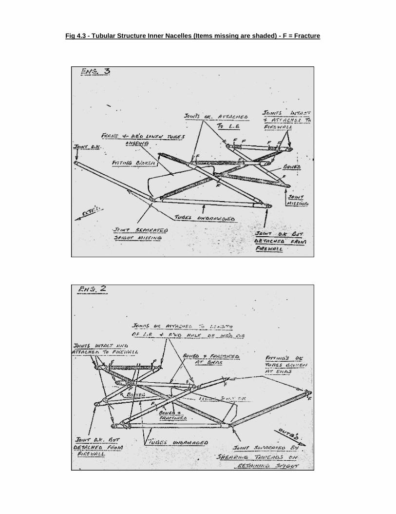
Fig 4.3 - Tubular Structure Inner Nacelles (Items missing are shaded) - F = Fracture
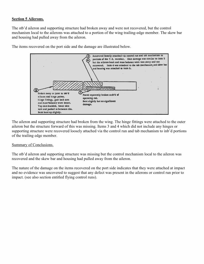
Section 5 Ailerons.
The stb’d aileron and supporting structure had broken away and were not recovered, but the control
mechanism local to the ailerons was attached to a portion of the wing trailing-edge member. The skew bar
and housing had pulled away from the aileron.
The items recovered on the port side and the damage are illustrated below.
The aileron and supporting structure had broken from the wing. The hinge fittings were attached to the outer
aileron but the structure forward of this was missing. Items 3 and 4 which did not include any hinges or
supporting structure were recovered loosely attached via the control run and tab mechanism to inb’d portions
of the trailing edge member.
Summary of Conclusions.
The stb’d aileron and supporting structure was missing but the control mechanism local to the aileron was
recovered and the skew bar and housing had pulled away from the aileron.
The nature of the damage on the items recovered on the port side indicates that they were attached at impact
and no evidence was uncovered to suggest that any defect was present in the ailerons or control run prior to
impact. (see also section entitled flying control runs).

Section 6 – Undercarriage and Mounting Structure.
The three units were recovered with the exception of the wheels, brake assembly and the inner cylinder
belonging to the stb’d main unit. The nose unit had broken away and was located in two pieces. The port and
stb’d main units were attached to the surrounding wing structure but the wheels, brakes and inner cylinder
had broken away from both. The port assembly was found early on floating with the tyres still inflated.
Nose undercarriage. The inner cylinder and wheels had broken clear of the outer cylinder. The gland nut was
split. The ram foot fitting was fractured and the forward portion of it, the door retraction ring and the torque
link below the fracture were missing. Wheel hubs were badly corroded and the tyres had small cuts in a few
places. The remainder of the undercarriage was located fixed to part of the mounting structure.
The triangulated structure supporting the main pivot was ripped away from the bulkhead but still attached to
the main pivot, the lower stb’d side member and bracing tube were missing but a portion of the port tube was
attached close to the pivot. The retraction jack was extended (i.e. undercarriage retracted) and bent, it was
attached to the locking unit and right had portion of the forward pick up beam. The left half of the beam was
recovered separately. The dampers were bent and damaged. The downlock receiver and cross beam with
some of the side supporting structure was recovered separately, but the uplock receiver and surrounding
structure had been torn out of the bulkhead and was missing.
The only items of the doors and operating mechanism recovered were the operating beam with some rods
attached and a small portion of the port door.
The direction of failure of the beam picking up the fw’d end of the jack, the bowing of the jack and dampers
and the tear out of the supporting structure from the bulkhead are all indicative of high fw’d inertia loads at
impact. The bulkhead at stn. 32 was badly fragmented caused by the ripping out of the uplock and
undercarriage support structure. The distortion and damage was consistent with high water forces being
applied to the bulkhead in an aft direction and reacted by fw’d inertia loads from the undercarriage. Most of
the catenary floor above the wheels was missing and although no direct evidence was available it is likely
that the undercarriage was forced hard-up, this contributing to failure of the torque links and ram foot fitting.
Main undercarriage units. The damage to the main undercarriage units and the surrounding structure is
illustrated in Fig. 6.1 and 6.2. The backstay fracture, spar boom impact mark, and bending of the jack are
common to both main units. It is reasoned that these were caused by up impact loads applied to the wheels
which in turn induced forces as shown by the arrows in Fig. 6.1 and 6.2.
On the port undercarriage the fitting at the trailing edge was bent forward and the bracing tubes failed in
compression, both probably caused by forward inertia loads on the undercarriage. Also downward inertia
loads might explain the bending of the door operating hook.
The bracing tubes on the stb’d side failed in tension. This suggests the absence of any appreciable f’wd load,
the tension failures being caused by a combination of aft and upward impact loads.
Summary of Conclusions. It has been established from the hydraulic system and verified by examination of
the undercarriage that all three units were retracted at impact, and the damage was readily explained as
having been caused by impact.
The damage to both main units is consistent with:
1. The aircraft descending rapidly, with only moderate forward speed and impacting at a shallow angle.

2. The stb’d wing being slightly low at initial impact thus inducing forward and down inertia loads onto
the port unit before the application of high up impact loads.
Stb’d Main Unit Fig. 6.1.
The unit was recovered attached to the wing structure with the jack, dampers, locks and supporting structure
accounted for, but the inner cylinder, wheels, brakes, gland nut, doors and operating mechanism had been
ripped away and were not recovered.
The torque links were attached to the outer cylinder and had broken away from the ram foot fitting at the
lower joint.
The downlock plungers were withdrawn, the jack was extended (i.e. undercarriage up) bent but attached at
both sides. The uplock was in position, the jaws were open and the lug on the undercarriage was undamaged.
The remaining damage is illustrated in Fig. 6.1.

Port Main Unit Fig. 6.2.
The unit was recovered attached to the surrounding wing structure with the jack, dampers, locks and
supporting structure accounted for. The inner cylinder, wheels and brakes had broken away and were found
floating with the wheels inflated. The doors and mechanism had ripped clear and only the operating beam
was recovered.
The torque links were attached to the outer cylinder and broken away at the ram foot fitting joint. The fitting
was cracked, the gland nut was missing and the door operating hook was bent out.
The downlock plungers were withdrawn, the jack was extended (i.e. undercarriage up) slightly bent but
attached at both ends. The uplock was damaged and the jaws were closed. The lug on the undercarriage had
been bent up and pulled out.
The remaining damage is illustrated in Fig. 6.2.

Section 7 Fuselage
Contents
7.1 Fuselage Pressure Shell
Introduction
Doors
Windows
Frames
Skin stringers and local reinforcing
Catenary floor and bulkhead at stn.132.
7.2 Cabin Floor and Associated Structure
Cabin Floor
Floor beams
Seat rails.
7.3 Cockpit Area
Introduction
Crew floors, seats and harness
Bulkhead at the rear of the cockpit
Other items.
7.4 Items from Cabin Interior
Introduction
Hostess seats
Life vests, seat belts and seats.
Seat cushions and pillows
Carpets
Other items
7.5 Personal Belongings.
7.6 Summary of Conclusions.
Section 7 Fuselage
Section 7.1. Fuselage Pressure Shell.
Introduction
The fuselage pressure shell was severely fragmented and about 15% of it was recovered. The location and
approximate size of the identified pieces are shown diagrammatically in Fig. 7.2. About 140 small pieces of
skin stringers and frames were identified as from the pressure shell but were not placed.
Most of the catenary floor beams in the nose bay area were recovered and it was possible to piece together
the pressure bulkhead at stn. 132. The pressure floor was attached between stn. 112 and 132, but forward of
this only small pieces were located fixed to the beams. The forward entrance door, port rear door and
fragments of the front door in the cargo hold were recovered.
Generally all pieces were badly distorted with stringers, frames and any local reinforcing structure still
attached. The largest and least damaged pieces were located at the rear doors.
Doors. There are six pressure sealed doors. Two on the port side and four on the stb’d side. Refer to Fig. 7.2.
The seals from the front and rear entry doors on the port side were recovered and the pressure bottle from the
nose-bay complete with gauge, charging point, filter, valves and local piping. Gauge reading 480 p.s.i. The
max normal is 300 and min. 50. Also recovered was the emergency pressure valve fitted at floor level by the
front entrance door. The lever was in the emergency position, i.e. open to cabin. The high gauge reading and
the position of the lever on the emergency pressure valve were almost certainly caused by impact loads and
no significance is attached to them.
Forward Entrance Door. (port side) This door and part of the surround structure were recovered and it was
possible to establish that the door was intact and securely locked at impact.
The bottom of the door was badly damaged and the front lower corner was missing. The distortion of the
lower surround structure was similar to that of the door and it was apparent that the main impact loads were
supplied via the lower surround structure in an upward and aft direction. The overall pattern of distortion
suggests that the door separated by peeling outwards and upwards starting from the bottom forward end.
Most of the door operating mechanism was intact the top and bottom front latch pins were missing but the
remaining four were attached and in the door closed position. The external handle was attached and closed,
but the internal handle was missing.
Rear Entrance Door (Port Side) The door and upper portion of the surround structure were recovered and
again it was possible to establish from the damage that the door was intact and securely locked at impact.
The impact loads were predominantly up, supplied via the lower surround structure. The bottom of the door
was folded up and out, finally separating from the fuselage by peeling outwards, starting from the bottom.
Front Cargo Hold Door (Stb’d Side) The lower half of the surround structure and two small pieces of the
door including the handle were recovered. The severe fragmentation of the door could only take place if it
was in position and securely locked at impact.
Rear Cargo Hold Door (Stb’d Side) Some of the surrounding structure was recovered but nothing of the
door, and it is impossible to say if the door was in position at impact.
Rear Entrance Door (Stb’d Side) This door is similar and opposite to the rear entrance door on the port side.
The surround structure at the top, bottom and forward sides of the door was recovered. The break up pattern
of this suggests that the latch pins were engaged, also the outside skin on the forward side near the top had
been forced out slightly, most likely by the door edge at impact. The indications thus are that the door was
intact and closed at impact.
Rear Freight Door (Stb’d Side) Nothing of the door or surround was recovered. The rear freight hold was
empty and is not normally accessible from the cabin.
Windows Items recovered: 3 pieces of perspex from the window panels, seals from the third and fifth
window port side, the window surround structure illustrated in Fig. 7.2. and a few other pieces of surround
structure not related to any particular window. No evidence was found of any defect or failure having been
present before the crash.
Frames Items recovered: Most of the main spar frame and trailing edge member pick-up frame, lower
portions of the leading edge frame, a portion of frame 132 above the pressure bulkhead on the port side,
about sixteen unplaced short lengths of typical light frame, and the segments of frame which are still
generally attached to the recovered skin items shown in Fig. 7.2. Altogether this makes up at 15% of the
total frame structure.
The double main frame was attached to the spar, but the upper portion between the top frame joints was
missing. The skin had torn away completely leaving the shear cleats attached to the frame. The portions
protruding below the spar, and the webs of the spar were badly damaged by impact loads applied in an aft
direction. The frame picking up the wing trailing edge member was broken in numerous places and a portion
of the lower starboard side was missing. Again the skin had torn completely away leaving the shear cleats
attached. The fractures close to the floor beam intersection and the overall distortion suggests the application
of impact loads in an aft and up direction applied to the bottom of the fuselage and reacted to some extent by
forward inertia loads at floor level.
A detailed examination of the items revealed nothing that could have been caused by forces other than
impact, and confirmed the evidence from doors, i.e. upward and aft impact loads were applied to the bottom
of the fuselage.
Skin Stringers and Local Reinforcing The location and approximate size of the placed items are shown in
Fig. 7.2. As far as could be assessed none of the unplaced items came from the rear pressure bulkhead area,
and it is therefore considered that further identification (which would be difficult if not impossible in a
number of cases ) would not alter the general impression, i.e. pieces recovered at random along the length of
the fuselage from the nose to stn. 800 indicating that fragmentation had taken place over this length. Some
wing structure was attached to the items in the region of the wing/fuselage intersection. The L.E. frame
joints and short lengths of the frame were attached to the forward pieces and the electrical looms and
pressure box were still fixed to the large portion on the starboard side. All were severely distorted by up and
aft impact loads. Another item warranting separate comment here is the structure over the rear doors. This
had a distinct crease line on the port side at an angle of 60º to the centre line measured from the rear and all
of the stringers were fractured along this line. This crease was probably caused by empennage loads at
impact.
The structure recovered was examined in detail and it was noted that in general the stringers, frames and
local reinforcing were still attached to the skin. No evidence or any signs of important pre-crash corrosion,
fire, explosion or any signs of in-flight failure due to pressure, shear or bending loads.

Catenary Floor and Bulkhead at Stn. 132 Recovered were: Most of the bulkhead at stn. 132, the support
beams forward of 132 with the exception of 72, the catenary floor between 112 and 132 loosely in position
and small fragments of the remainder of the caterary floor attached to the recovered beams. The majority of
the beams had broken away adjacent to the fuselage side and the lighter forward beams were bowed up and
twisted (lower boom aft and up). The damage was almost symmetrical about the centre line. The catenary
floor between 112 and 132 was loosely attached to the adjacent beams but was badly damaged particularly
on the stb’d side in the region of the jump seat. Forward to stn. 112 and below the crew floors the catenary
floor had broken away from the beams and was not recovered. The most severe damage occurred in the
region of the crew seats and nose wheels.
The bulkhead at stn. 132 supporting the nose undercarriage and taking pressure loads as badly damaged and
portions had broken away with the nose undercarriage support structure. The break-up pattern could be
explained by aft impact loads and associated forward undercarriage inertia loads. The uplock receiver and
the surrounding area of the bulkhead were missing.
Examination of the structure did not reveal any signs of pre-crash defect or failure.
7.2 Cabin Floor and Associated Structure
Cabin Floor The portions of the cabin floor are shown in Fig. 7.1. The unplaced portions consisted of sixteen
small pieces of the side panels and one small piece of the centre panel.
About one-third of the floor was recovered, and the pieces were distributed throughout the length of the
cabin. The centre panels have an end grain Balsa core and were recovered floating. The side panels are of
conventional construction. In the region of stn. 323 bits of the floor beams were loosely attached to the side
panels, elsewhere they had broken completely away.
Compression folding under forward loads was apparent particularly on the front panels. There was also a
general downward dishing of the panels in the central area of the fuselage and the access panel adjacent to
stn. 485 had been forced down and impacted hard onto the rear face of the main spar.
The cabin floor could have had a bearing on the accident to the extent that a sudden de-pressurisation could
cause deformation and fouling of the control runs. This hypothesis was investigated, most of the control runs
and floor were missing and although some downwards dishing of the aisle panels in the control area of the
fuselage had taken place there was no evidence to suggest that this was caused other than by downward
inertia forces or by inflow of water at impact.
Floor Beams Recovered were: Pieces from most of the floor beams forward of the main spar, most of 501,
short lengths of 523 and 606 and thirteen other unplaced bits of beam and support structure. The beams were
badly damaged and generally broken at inner seat rails and close to the fuselage side. Beam 198 was
virtually complete and symmetrically kinked at both inner seat rails by forward loads applied by the rails. On
some of the forward beams bits and pieces of the control runs and supporting members were attached.
The damage was readily attributable to impact forces.
Seat Rails About 15% of the seat rails were recovered in short lengths and some pieces were still attached to
the floor structure forward of the spar. Immersion in the sea had caused severe corrosion and it was noted
that in some cases the seats had separated from the rails by shearing the edges of the retainers.

7.3 Cockpit Area
Introduction Recovered were the pilots and co-pilots floor with the seat mounting structure, the back frame
of the pilots seat with shoulder harness attached, portion of the co-pilots shoulder harness, the jump seat,
empty radio rack frame from the stb’d side, cockpit entry door and the aft face and core of the bulkhead at
the rear of the cockpit on the stb’d side. The control runs were in position under the pilots floor.
Floors Seats and Harness The pilots floor was virtually complete and damage consisted mainly of
compression folds in a fore and aft direction associated with bending and tearing. The pilots right shoe was
recovered trapped in a compression fold just clear of the right rudder pedal. The co-pilots floor was more
severely damaged and the area just forward of the seat was missing.
The seat retaining bolts were torn out of the mounting channels and only the back frame of the Captains seat
was recovered. The shoulder harness was attached complete and secured to the lock-on harness/release
mechanism and inertia reel. The strap was pulled out of the reel to the full extent. The lap straps were
missing but one of the fittings was attached to the lock-on harness/release mechanism and the other had been
torn out. Only the straps of the co-pilots shoulder harness below the Y joint were recovered. There were
signs of over straining on one of the straps at the end fitting and the pick-up lugs on both fittings were bent.
The evidence clearly indicates that both flight crew were using the shoulder harness at impact and that the
Captain’s lap strap was fastened. Most probably the co-pilot’s lap strap was also fastened. The jump seat had
the back and lap strap attached. It was unoccupied and appeared to have broken clear and collapsed mainly
under up loads.
Bulkhead at the Rear of the Cockpit on the Stb’d Side.
The fore and aft face of this bulkhead were located soon after commencement of recovery operations and it
was pieced together. A portion was cut away to study a stain which subsequently proved to be blood. At a
later stage interest was directed to a cluster of small circular holes in the upper right side, some of which
were filled with a plastic metallic substance. However a detailed investigation revealed that holes were
caused by repeated screwing and unscrewing of the hat-rack to the bulkhead which is removed during major
checks and may or may not go back in exactly the same place on some aircraft. Also plastic type filler is
used by the Aer Lingus furnishing shops to plug redundant holes.
Other Items The curved frame of the stb’d radio rack was badly damaged at the bottom forward corner by
impact loads, and examination of the remaining items revealed nothing not due to impact.
7.4 Items from Cabin Interior
Introduction The configuration in use is illustrated in Fig. 7.1. Seats, bulkhead, toilets, galleys, carpets and
other fixtures and furnishings in the main cabin were torn loose and shattered by impact forces. The bits and
pieces recovered were divorced completely from the fuselage and they are noted and discussed below.
Hostess Seats
Aft Seat The seat base was recovered with the lap strap fitting missing and examination of the seat fittings
showed that the stb’d lap strap had become detached from the retaining bolt, but, on the port side the
retaining bolt was missing. Damage to both the seat base and frame was slight.
Double Seat at Main Entrance Door The items recovered were: the back padding, the seat base with lap strap
fittings, pieces of the fixing brackets and one sliding tube attached, and the port sliding tube which had
broken away. The support frame and the lap straps which had become detached from the retaining rings
were missing. The back padding was in good condition, the seat covering was ripped and the seat pans were
distorted probably by blows received during break-up, but the tubular frame supporting the seat was
undamaged.
As noted damage to both seats was superficial. This is particularly true of the aft seat which is f’wd facing
and had the support frame still attached. There were no signs of overstraining at the lap strap fittings and
loads from the seat belts would not normally cause failure of the strap hook or indeed of the missing bolt.
The evidence is conflicting but a possible explanation is that the straps sprung free during break-up. A few
lap straps found separately but not necessarily from the hostesses seats had separated in this manner. As
regards the missing bolt, it should be noted that the aft seat was not recovered until 18 months after the
accident and there is the possibility that corrosion could weaken the missing nut/bolt sufficiently to permit it
to fall away during recovery.
The above evidence although not entirely conclusive indicates that the seats provided for the hostesses were
not being used. However, although the full complement of passengers were aboard, two were infants, and
this could leave two passenger seats vacant in an emergency.
Life Vests, Seat Belts and Seats
Two life vests were recovered. These were still in their covers and unused.
The seat belt items recovered consisted of: One belt complete and fastened. Attached to a portion of frame
on one side and broken away at the small fixing pin on the other.
Three lap straps, two short and one long. The long one was fixed to a portion of seat and the attachment
fitting was twisted. The short straps were unlocked from the seats. Examination revealed no clear evidence
of overstressing and it was not possible to determine if in fact they were fastened at impact.
Damage was severe on the passenger seats and the various components recovered are listed:-
One gold covered seat back with folding table
Six arm rests with bits of support tube attached
Remnants of 9 seat back tables
Two triple seat support frames
Two double seat support frames
Three other pieces of side frame tubing.
The seat back had broken away at the bottom attachment and there was some overall distortion and signs of
impact on the aft side. The steel side frames had broken clear at the attachment to the seat base and away
from the seat rails. In a number of cases the frames had parted from the seat rail by shearing the edges of the
retainers. All were badly buckled by forward and down loads with the exception of one triple seat frame.
Three of the arm rests had been forced hard down at the front but only slight distortion was apparent on the
other three.
Very high down inertia loads would be experienced at impact as well as f’wd loads and if occupants were
strapped in, these loads would distort the seat frames. One of the triple seat frames although broken away
was not distorted, implying that the occupants supported by the frame were not strapped in. The evidence
however, both from the seats and lap straps is inconclusive and doubt must remain.
Seat Cushions and Pillows
Recovered:
6 seat cushions with green covers
1 seat cushion with gold cover
10 seat cushions without covers
1 green cover
3 gold covers
2 small pillows without covers
1 large pillow with green cover
)
)
)
)
)
Total:
17 cushions
7 green covers
4 gold covers
Some fuel contamination was apparent and a few were cut and holed otherwise damage was slight. To
investigate the possibility of any fragments from an explosive device being imbedded in the foam it was
decided to X-ray all of the items. The results were negative.
The green and gold covers are distributed in a random manner and no particular significance can be
attributed to the relative numbers of green and gold covers found.
Carpets Seven strips of carpet were recovered, varying in length from 2 ½’ to 11 ½ ‘. Apart from some tears
the condition was generally good and no unaccountable damage was noted.
Other items
The remaining items from the passenger cabin recovered included: Overhead water tank (mounted on the
roof between toilets) two water heaters from toilet washbasins, one with control unit attached, service panel,
polythene piping connecting the foregoing items, toilet container, toilet seat, hot water container from the
galley and cabin fire extinguisher.
Forty feet of the centre aisle roof panel with lights, P.A. speakers and electrical wiring attached, also buffet
control panel at the rear port side of the fuselage.
Escape chute cover and odd bits and pieces of internal bulkhead and secondary support structure, three
window blinds and surround panels, sound proofing, hat-rack edge member and cold air ducting.
The items were dislodged from their mountings and the damage in general was typical of that caused by
impact. One of the window blinds was badly discoloured on the inside.
7.5. Personal Belongings A small amount of personal luggage was recovered. The few rigid items were
broken and crushed, otherwise the only damage was that caused by immersion in the sea.
7.6. Summary of Conclusions
1. The impact, associated inertia forces and the subsequent ingress of water under pressure caused complete
disruption of the structure and cabin interior. The nature of the damage suggests that the aircraft struck the
water right way up and at a shallow angle with a high velocity of descent and moderate forward speed.
2. The fragmentation pattern shown in fig. 2 implies that the fuselage structure from the nose to stn. 800 was
at least capable of supporting the flight loads imposed up to impact.
3. There is positive evidence that three of the doors were intact and closed at impact. There is some doubt
about the Stb’d rear entry door and no evidence is available on the rear cargo hold door and the rear freight
door both on the stb’d side.
4. No evidence was found to suggest fire, detonation of an explosive device, or bits of the fuselage skin
having been shed in flight causing depressurisation and striking or jamming controls. The possibility of any
of these having occurred however cannot be completely eliminated in view of the small amount of fuselage
wreckage recovered. (See also note below).
5. The flight crew were strapped in and using the inertia reel shoulder harness at impact. It was not possible
to establish from the wreckage if in fact the cabin staff and passengers were or were not all strapped in at
impact.
Note
Extensive corrosion checks were carried out by (Scottish Aviation Limited) and the aircraft was released
during February, 1967. Two of the rear belly panels were replaced and other areas of light corrosion were
cleaned out and reprotected and repaired where necessary. It should also be noted that the corrosion
normally found takes the form of localised deep pockets generally visible externally before the structural
integrity of the pressure shell is seriously impaired. The lower pressure differential in use on the aircraft (4 ½
p.s.i. design max 6 ½ p.s.i.) further reduces the risk of having a serious failure.
Attached Diagrams
Fig 7.1 - Diagram 1
Fig 7.1 - Diagrams 2,3 & 4
Fig 7.2

Fig 7.1 - Diagram 1

Fig 7.1 - Diagrams 2, 3 & 4
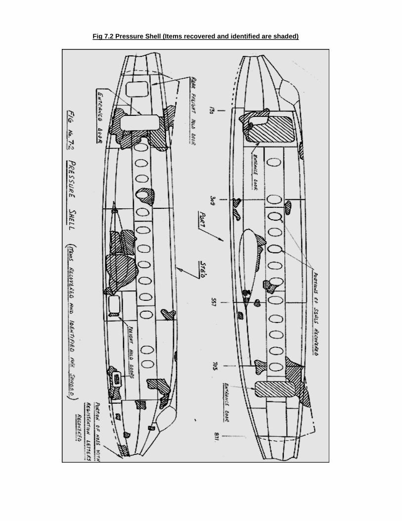
Fig 7.2 Pressure Shell (Items recovered and identified are shaded)
Section 8 Fin and Rudder
Recovered were:- The upper two-thirds of the fin and rudder structure complete, about 3 sq. feet of skin
from the lower stb’d side of the rudder, the trim and rudder servo tab above the upper skew bar attachment,
the rudder torque tube with a portion of the rudder and rib attached, some of the dorsal extension attached to
the fuselage skin and the removable panel at the top of the dorsal extension.
The rudder torque tube is dealt with as part of the flying control runs and the pertinent damage to the rudder
and fin structure is illustrated on Fig. 8.1.
The upper two-thirds of the fin and rudder was complete and recovered in one piece. The rudder was
attached at the three hinge points and the trim and servo tab controls were intact above the fracture. The
nature of the failure and the general skin panting and buckling particularly noticeable towards the lower end
was undoubtedly caused by high down inertia forces at impact.
The rudder had been forced forward and it was distorted above both upper hinge points by inertia loads
forcing it down onto the hinge arms. The mass balance weight on the L.E. of the rudder was also forced
down and had pierced the top two diaphragms on the fin extension below the second hinge. Subsequent to
this the rudder had been twisted, and the displaced mass balance was clear of the stb’d side of the fin. The
stb’d side of the fin extension between hinges 2 and 3 was dished inwards and a hole had been punched in
the rudder skin on the stb’d side below and aft of the second hinge. The top of the rudder was damaged by
what appeared to be two separate blows, one coming from the top and slightly inclined to the stb’d side and
the other close to the tab hinge sigot and from the back, the latter blow displacing the hinge spigot. The
navigation light on top of the fin was missing, the surrounding structure was damaged, and the hot air de-
icing vent covers on the fin were corroded almost completely away.
The upper portion of the tab was recovered separately, it had parted from the upper hinge spigot and was
broken above the skew bar. The port side of the tab was creased along its length as shown in Fig. 8.1. A
short length of tab was still attached to the skew bar and the fractured surfaces on this were severely
mangled.
Summary of Conclusions
Insufficient structure was recovered to enable a thorough break-up analysis to be carried out and it is
impossible to say what direction the structure was thrown after break-up or indeed what other pieces of
wreckage it may have come in contact with. For this reason the damage at the top of the rudder, the dishing
and hoeing on the stb’d fin skin, and the tab creasing is not readily explainable but there are clearly no
indications that it is other than impact damage.
The rest of the damage is indicative of the fin, rudder, and tab being on the aircraft at impact and being
subjected to impact forces on the bottom and inertia forces increasing in magnitude down the fin and rudder.
There were also forward inertia loads present. It would appear that the structure below the fracture collapsed
essentially under compression loads and this could twist the rudder torque tube off in the manner described.
(see section on flying controls).
In conclusion it is apparent that the fin, rudder and tab were on the aircraft at impact and no evidence was
uncovered to suggest the presence of any damage or defect which would prevent normal operation. The
location of the piercing of the diaphragms on the fin extension by the mass balance signifies that when the
impact forces were applied the rudder was slightly left of centre.

Attached Diagrams
Fig 8.1
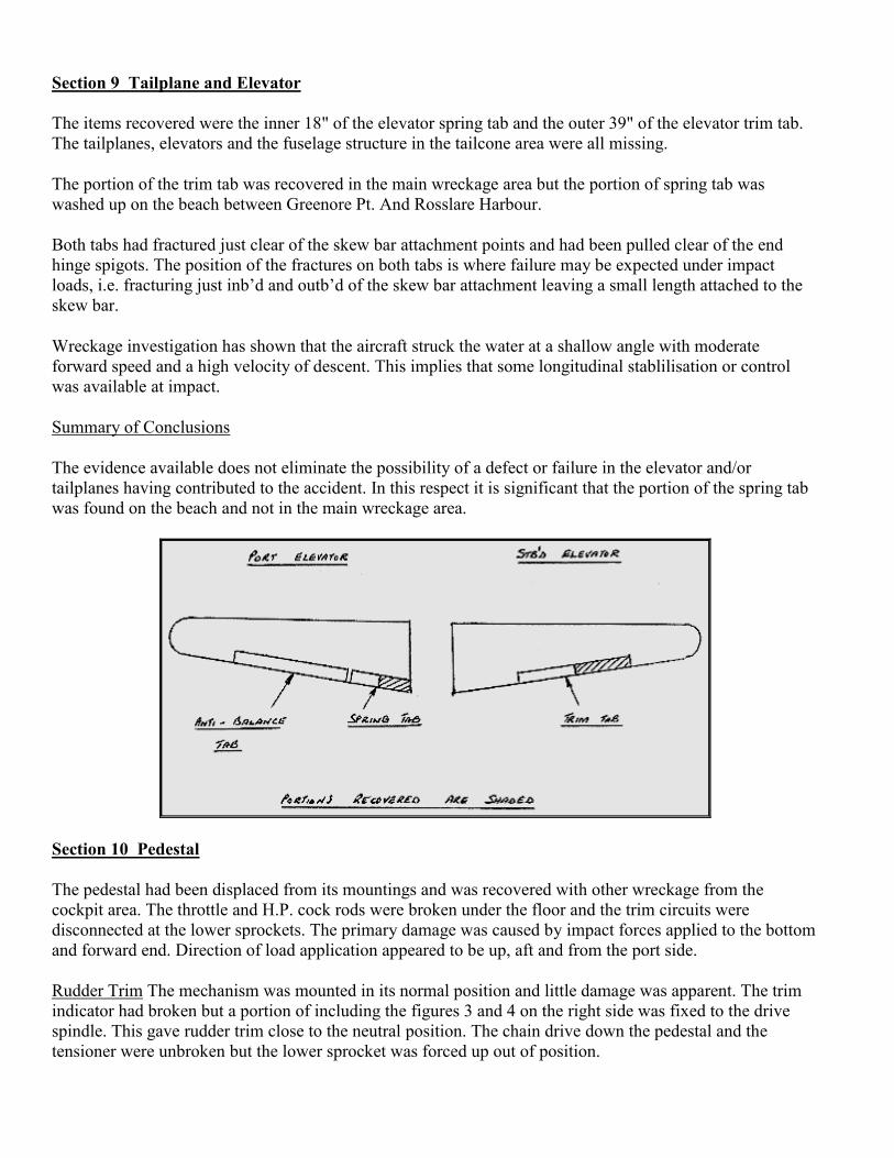
Section 9 Tailplane and Elevator
The items recovered were the inner 18" of the elevator spring tab and the outer 39" of the elevator trim tab.
The tailplanes, elevators and the fuselage structure in the tailcone area were all missing.
The portion of the trim tab was recovered in the main wreckage area but the portion of spring tab was
washed up on the beach between Greenore Pt. And Rosslare Harbour.
Both tabs had fractured just clear of the skew bar attachment points and had been pulled clear of the end
hinge spigots. The position of the fractures on both tabs is where failure may be expected under impact
loads, i.e. fracturing just inb’d and outb’d of the skew bar attachment leaving a small length attached to the
skew bar.
Wreckage investigation has shown that the aircraft struck the water at a shallow angle with moderate
forward speed and a high velocity of descent. This implies that some longitudinal stablilisation or control
was available at impact.
Summary of Conclusions
The evidence available does not eliminate the possibility of a defect or failure in the elevator and/or
tailplanes having contributed to the accident. In this respect it is significant that the portion of the spring tab
was found on the beach and not in the main wreckage area.
Section 10 Pedestal
The pedestal had been displaced from its mountings and was recovered with other wreckage from the
cockpit area. The throttle and H.P. cock rods were broken under the floor and the trim circuits were
disconnected at the lower sprockets. The primary damage was caused by impact forces applied to the bottom
and forward end. Direction of load application appeared to be up, aft and from the port side.
Rudder Trim The mechanism was mounted in its normal position and little damage was apparent. The trim
indicator had broken but a portion of including the figures 3 and 4 on the right side was fixed to the drive
spindle. This gave rudder trim close to the neutral position. The chain drive down the pedestal and the
tensioner were unbroken but the lower sprocket was forced up out of position.

Elevator Trim Again the mechanism was mounted in its normal position with little apparent damage. The
wheel on the port side was loose but the stb’d one was fixed. Corrosion had removed the markings on the
stb’d side but by noting the position of the zero mark a trim setting of 2 ½ units nose down was established.
The chain drive in the pedestal was unbroken and attached to the lower sprocket which had been forced out
of position, the tensioner had broken away from its mountings. The trim motor, drive shaft, clutch and
annulus gear were attached.
Aileron Trim The indicator in the pedestal is electrically operated and was firmly in position with the wires
attached, but no useful information was obtained from it.
Flaps The selector switches were positioned as follows;-
Main flap selector in the flaps up position
Main motor trip and reset switch in the neutral position
Emergency engage switch locked in the normal position
Emergency selector switch in the centre (off) position.
Undercarriage The undercarriage operating lever was in the down position. It was concluded that it had
moved to this position on impact since the actuator and control valve in the hydraulic cupboard were both in
the undercarriage up position.
Control Locks The control lock lever was in the off and stowed position and the top of the lever was
missing. The mounting was distorted but the chain drive was in position through the pedestal and attached to
the rod under the cockpit floor.
Throttles and H.P. Cocks The throttle lever group was seized in position and levers 1, 2 and 4 were bent to
the right and lever 3 slightly to the left. The position of the levers varied from ¾ " to 1 ¾ " from the open
position.
The H.P. cock levers were damaged and seized in position. The quadrants were broken and the position of
the levers varied from almost fully closed to open.
The engine control rods and lever groups down the pedestal and below the floor were displaced and broken
by upward impact forces.
Auto-Pilot The control panel was removed for investigation and the results are presented in the auto-pilot
report.
The pedestal was sent to the B.A.C. laboratories at Weybridge for a detailed strip examination. No useful
additional information was obtained and it was concluded that the damage sustained was caused entirely by
impact forces.
Summary of conclusions No evidence was uncovered to suggest the presence of any pre-crash defect or mal-
function, and the extensive crash damage sustained must in general render unreliable the engine and flying
control settings noted.
Section 11 Flying Control Runs
11.1 Introduction
The fragmentation of the airframe structure at impact caused disintegration of the control runs. Most of the
push-pull rods recovered (about 25% of the total) were crushed, broken and trapped by the distortion of the
surrounding structure and the magnesium levers were severely corroded by immersion in the sea. The
various items recovered from the primary control runs and the trim and control lock system are noted below.
11.2 Controls in the Cockpit
Rudder The rudder bar assemblies were attached to the cockpit floor and were complete with the exception
of: the pilots left hand pedal and foot brake mechanism, interconnecting rod and the magnesium lever at the
base (probably corroded). The left arm of the pilots rudder bar was bent forward and down and both arms of
the co-pilots rudder bar were bent down. Distortion was more severe on the co-pilots side. The pilots right
shoe was retrieved. It was trapped by the heel in a compression fold in the floor aft of the right pedal and the
floor was pierced below it.
Elevator A portion of wreckage was recovered comprising a length of cross tube, end bearing, lower part of
the right elevator lever and portion of the fuselage skin and static vent. Nothing else was recovered.
Aileron The only portion of the aileron circuit recovered was the cross beam, chain pulley shaft and chains.
The cross beam had separated from its mountings and the chains were broken.
11.3 Control runs in the pressurised area of the Fuselage
The rods under the pilots floor back to the lever group at stn. 139 were trapped in position and portions of
the forward rods on the elevator and aileron circuit were missing. The rods were flattened, bent and fractured
at stn. 112. The lever group shaft and supporting structure at stn. 139 were located but the levers were
missing (probably corroded). The aileron servo motor which actuates the circuit at stn. 139 was not
recovered.
Short lengths of rod were found attached to the mounting structure on three of the forward fuselage
underfloor beams. One was located at stn. 282 but the others could not be identified. A portion of the aileron
rod bent over the roller guides was protruding from the back of the main spar.
The other items recovered were one of the aileron control run pressure boxes at the fuselage side with the
lever shaft attached, (lever corroded) and six short unidentified portions of control rod making up a total
length of about 9 feet.
11.4. Controls aft of the Rear Pressure Bulkhead The items recovered in this area were the rudder torque
tube with associated mechanism and the trim and servo tab control run complete above the fin and rudder
fracture. A portion of the fuselage mounting bracket was attached to the rudder torque tube. It was twisted
and fractured and had impacted the top and bottom edges of the torque tube slot. (One slight mark central on
the top edge and two on the lower edge 1½" from each side. The mark on the stb’d side was deeper with
signs of double impact). The nature of the damage suggests that the rudder was moving towards the left
during break-up and examination of the fin and rudder confirmed this.
A piece of rudder end rib was attached to the top of the torque tube. The control rod was broken at the
bearing attachment to the torque tube plates and the plates were bent down.
The rudder servo lever was fractured across the lightening hole adjacent to the torque tube. The distortion of
the rudder end rib, the direction of failure of the bracket attaching the torque tube to the fuselage, the
downward distortion of the lower plate and the direction of rivet shear at the torque tube joint in the rudder
are all indicative of the torque tube having been twisted off in an anti-clockwise direction looking forward.
Insufficient structure was recovered to study the failure mode in the area but the fin and rudder had been
severely compressed which apparently led to fragmentation at the lower end and this type of loading could
twist the torque tube clear in the manner described.
The tab control rod in the rudder had broken at the screwed joint above the lower torque tube and the
mechanism above this fracture was mounted in position in the recovered portion of fin and rudder. The
balance weight was intact and a short length of tab was attached to the skew bar. The rudder torque tube was
sent to B.A.C. laboratories at Weybridge for examination. When checking the tab-spring pre-tension it was
found that an incorrect spring had been fitted and that it was similar to the one fitted to the elevator torque
tube which has a lower rate. It was impossible to establish where or when this spring came to be fitted but
enquiries indicated that the time lapse since initial misassembly was greater than a year and this would
indicate that the consequences are not serious.
A complete investigation to determine what effect this would have on the rudder/tab operation was
undertaken by B.A.C. and their findings are summarised below:
1. For all normal flying it is possible that the pilot would not notice the lighter rudder feel. If he did, he
would probably class the aircraft as slightly more responsive to rudder than most.
2. In cases of an engine cut on take-off, crosswind take-offs and landings, the rudder would again
appear somewhat more responsive.
3. It is possible that a small decrease in trim sensitivity might be noticed. This would probably be so in
case of trimming out the rudder to hold asymmetric engine power.
4. Again, the incorrect spring would not effect the rudder channel of the auto-pilot, since the rudder
servo motor drives the rudder directly via the torque tube and not via the spring tab mechanism.
5. The possibility of overstressing the rudder has been investigated. Even if the most severe B.C.A.R.
manoeuvre case is considered (300 lbs. pedal force application by the pilot), the aircraft structure will
not experience ultimate load conditions, but it is considered that some structural deformation could
possibly occur. The case of an autopilot runaway would be as with the correct spring fitted, since the
servometer does not control the rudder via the spring tab mechanism. The effect of the lighter spring
would, however, make it slightly easier for the pilot to recover from the runaway condition.
6. The original flutter information for the aircraft type was reviewed and it is considered that the
incorrect spring fitted would not cause flutter within the normal speed envelope for the aircraft.
It should also be noted that the damage to the fin, rudder and tab structure recovered was indicative of their
being on the aircraft at impact and that no evidence was uncovered to suggest the presence of any damage or
defect which would have prevented normal operation.
11.5. Aileron Control Run in the Wings The items recovered on the port side were: Two short lengths of
control rod attached to the aft portion of the swinging link. A 9’ length between the engines which was
attached to the wing. The rods were unbroken but bent and forced outwards beyond the normal movement.
The control run local to the port aileron which was loosely attached to a portion of the wing T.E. member
and an outer portion of the aileron. Included in this were the skew bar and housing, torque tube and lever,
and about 8’ of the control rod and the servo tab actuating mechanism. The mechanism was displaced and
damaged and the rods were broken.
The items recovered on the stb’d side were: An 11’ length between engines 3 and 4. The rods were broken
but about half the length was in position and this had been forced outwards beyond the normal movement.
The control run local to the stb’d aileron comprising 12" of control rod attached via the lever to the aileron
torque tube and skew bar. The assembly was loosely attached to a short length of the wing trailing edge
member and the skew bar and housing had broken away from the aileron. No aileron structure was
recovered.
11.6 Position of Control Rods
An attempt was made to establish control surface settings as given by:-
a. The positions of the centre rods under the pilots floor,
b. The protrusion of the rods from under floor beam at stn. 282,
c. The protrusion of the aileron rod at the back of the main spar,
d. Roller guide indentations on the aileron control run close to the port aileron.
and the results are summarised below.
Rudder:- Position (a) Full right rudder
(b) corresponds approx. with position (a)
Elevator:- " (a) Overtravelled slightly beyond full up elevator,
(b) Overtravelled in a down elevator direction,
Aileron:- " (a) Stb’d aileron partially up
(b) Close to the neutral position
(c) Stb’d aileron approx. fully down.
(d) Stb’d aileron approx. half down.
11.7 Trim Circuits The elevator and rudder trim circuits were intact in the pedestal down to and including
the sprockets and chains below the pedestal, some cable was also attached. The spilned drive shafts between
the sprockets were missing on both circuits but the elevator trim servo drive was located. Some lengths of
control cable were recovered and also four of the pulley groups down the fuselage.
The items recovered in the tail cone area were the portion of the rudder trim circuit attached to the torque
tube and the upper portion of the wervo trim mechanism in position in the fin and rudder structure. The
aileron trim tab on the stb’d wing is electrically actuated and the only item recovered was the indicator in the
pedestal.
11.8 Trim Positions
Rudder The indicator in the pedestal gave rudder trim close to the neutral position. By dimensional check of
a fixed point on the trim actuating rod with a reference point on the rudder torque tube, a trim tab angle of
two divisions port tab was indicated. One or both ends of the system were affected during break-up and it
was therefore impossible to establish the likely trim position before impact.
Elevator The setting obtained from the pedestal was 2 ½ units nose down. This reading is abnormally high
but because of the lack of corroborating evidence and the fact that the setting may have altered during break-
up no reliance can be placed upon it.
Aileron No evidence available.
11.9. Control Lock System The mechanism in the pedestal was complete. Also located was the control run
back to the wing and along both wings to the No. 3 flap beams. The remainder of the system was missing
with the exception of one gust lock arm on the port side which was attached to the outer aileron.
The lever in the pedestal was in the stowed position (i.e. locks off).
11.10 Control Stops None were recovered.
11.11. Summary of Conclusions No evidence was found to suggest the presence of pre-impact damage or
malfunction, but since most of the control runs were not recovered the possibility of some defect in them
contributing to the accident cannot be eliminated.
During examination of the rudder torque tube it was found that the wrong type of spring had been fitted. The
effect of this on the rudder/tab operation was fully investigated and it was concluded that it had no bearing
on the accident.
Attempts were made to establish the control surface settings at impact from the damage and position of the
control rods recovered. These were found to be contradictory on the elevator and aileron and the rudder
position conflicts with the evidence obtained from examination of the fin and ruder structure.
The trim settings obtained from the pedestal are regarded as unreliable since they may have been affected
during break-up.

Section 12 Fuel System - Wing & Nacelle Installation
The disruption of the wing structure at impact caused severe damage to the fuel system. The bladder cells
were torn apart and the portions recovered were attached to the wing structure. A substantial amount of
piping from the refueling, interconnect, flow, and ventilating systems was recovered and some of this was in
position in the wings and nacelles.
Items recovered from the fuel flow system:
The boost pumps from the No. 4 tank
Power drain valve – closed
Both inter-engine valves, - actuators missing, valves open
No. 4 engine low pressure valve with actuator – open
Flowmeter mounted in No. 4 nacelle, 8 pacitor tank units
2 drip tubes, one differential switch and one low pressure warning switch.
The fuel pumps were within the isolation chambers and attached to pieces of the lower wing skin.
Examination revealed no rotation marks on either of the units and it was concluded that at the time of impact
they were not under the influence of electrical power.
The valve settings noted are correct for en-route flight.
Refuelling and Defuelling System The defuelling valves from the inner tanks were recovered. The port valve
was closed but the stb’d valve was partially open. It was considered that this had been caused by impact
forces.
The pressure refuelling connection was in position on the stb’d wing but missing on the port side, and two of
the float switches were recovered.
Venting System Two of the float valves were recovered. The sealed floats in these were crushed probably
due to water pressure in the sea-bed.
Summary of Conclusions The valve settings noted are normal for en-route operation and examination of the
bladder cells, plumbing and units recovered revealed no signs of pre-impact leakage, fire or malfunction
which may have restricted the fuel supply to one or more of the engines.
The fuel taken aboard prior to departure from Cork was 1000 galls. 290 galls. in each of the outer tanks and
210 galls. in each of the inner tanks. Estimates show that at the time of the last message, and assuming
normal operation, the fuel content would have been approximately 110 galls. in each inb’d tank and 275
galls. in each outer tank. At this stage one boost pump is switched on in each outb’d tank and the remaining
boost pump operating in each inb’d tank is switched off. The evidence obtained from the two pumps
recovered indicates that this in fact had not taken place prior to the accident.
Section 13 Hydraulic System
The hydraulic system supplies the necessary power for retraction and extension of the landing gear, for
operation of main wheel braking and nose wheel steering. The following items were recovered:
From hydraulic cupboard;
Header tank and attached filter
U/c selector valve and actuator
Hand pump
Emergency change over valve
By-pass cock
Associated piping, non-return and relief valves.
From nose area.
Hydraulic service panel, badly damaged. No indicator reading could be obtained.
1 H.P. filter and 2 micronic filters.
Automatic cut-out valve.
The main accumulator and one brake accumulator.
Brake control valve, maxaret on-off valve and portion of parking brake cable attached to the crew floor.
The four foot brake actuators. The pilots left hand actuator was badly damaged.
2 pressure reducing valves for brakes.
Steering selector valve minus operating and follow-up mechanism.
Steering jacks, portions of 2 way relief and shut off valves and associated piping were recovered with the
nose leg.
Nose u/c jack and dampers attached to the oleo and portion of the top beam. The jack was fully extended, i.e.
u/c retracted position.
From port main u/c areas
Maxaret system and brake assembly recovered with wheels and inner cylinder.
Jack and damper in position. The jack was extended, i.e. u/c retracted position.
Brake lines and walking joints attached to the outer cylinder.
From stb’d main u/c area
Jack and damper in position. The jack was extended and badly bent, i.e. u/c retracted position.
Brake lines and walking joints attached to the outer cylinder.
In addition to the above most of the piping from all parts of the aircraft were recovered, these included
joints, some pressure transmitters, non-return and choke valves. In general this was entangled in the
wreckage and some dismantling was necessary. The engine driven pumps were not recovered.
Summary of Conclusions Examination of the components recovered revealed no evidence of fire, pre-impact
defect or abnormal operation in the hydraulic system.
The landing gear lever selector in the pedestal gave u/c down but the control valve and actuator and the
position of the jacks indicated u/c up. The evidence clearly indicates that the nose and main u/c were fully
retracted at impact and it is probable that the pedestal selector was displaced by impact forces.
Section 14 Air Conditioning & Pressurisation System
The following items were recovered attached to the wing and/or nacelle structure:-
No. 2 Engine: Air intake, filter and ducting from aft of the main spar up to the primary silencer.
No. 3 Engine: Ducting from the compressor to the primary silencer.
No. 4 Engine: Air intake, filter and some of the ducting attached to the T.E. member. A 5’ length of the
ducting outb’d of No. 3 nacelle had broken away but the remainder from the No. 4 nacelle to the primary
silencer was attached.
The remaining items recovered are listed below. These had broken away from their mounting structure.
One compressor (serial No. missing, not possible to identify).
Two primary silencers (port and lower stb’d) and one secondary silencer.
The three spill valves and the actuator from No. 3.
A cabin pressure non-return valve.
Cockpit heat valve.
A portion of the intercool – valve and associated operating mechanism.
Temperature control gear and mounting structure (fixed under the floor at stn. 630). The actuator was
missing but the control and manual over-ride mechanisms, micro switches, Desynn transmitter were
attached.
The pointer was on the dividing line, between Intercool and Refrigerate.
The large dual heat exchanger unit with local pieces of outlet pipe attached.
Numerous bits of ducting.
Cabin Altitude indicator.
Cabin pressure controller attached to overhead panel.
Summary of Conclusions Damage to the items recovered was severe and the ducting badly flattened. During
examination attention was directed towards any signs of overheating, contamination of ducts or lagging,
leaks or excessive pressures which may have indicated abnormal operating conditions in the system. Nothing
unusual in this respect was noted.
The housing of the ventilating fan and motor were recovered but the fan rotor was missing. The scoring
inside the housing suggests that the fan rotor was rotating at impact. The fan is not normally driven when the
aircraft is pressurised but the airflow would cause it to spin.
The cabin altitude indicator, and cabin pressure controller were investigated. Briefly the settings on the cabin
pressure controller were normal, but the height indicator was damaged and the reading regarded as
unreliable.
Spill Valve Settings noted:
Switches Actuators Valve position
No. 2 Closed - Closed
No. 3 Auto Open Closed
No. 4 Close - Partially Open

These are contradictory and unreliable. Usually, spill valves are set to auto and start to open below 12,000’.
The cockpit heat valve was free and no information could be obtained from the intercool valve or the cabin
pressure non-return valve. In conclusion it should be noted that investigation of the system revealed no
evidence of faulty operation or defect prior to impact.
Section 15 Engine Fire Warning and Extinguisher System
The items recovered were: The four fire bottles, and two inertia switches at the No. 4 engine, breather pipe
detector switches from engines 1, 2 and 3, the spray rings attached to the engines, pieces of piping and fire
wire and the fire control panel mounted above the instrument panels.
The firing heads were attached to the bottles. The two inertia switches recovered were tripped but none of
the bottles were discharged. The fire control panel P was severely damaged and no relevant information
could be obtained from it.
The damage sustained by the spray rings, pipe lines and fire wire was consistent with the impact forces.
Summary of Conclusions It is considered that the systems were complete prior to impact. Although the two
inertia switches recovered were tripped none of the fire bottles had been discharged. There were no signs of
fire on the engines or nacelles.
Section 16 Thermal De-Icing System
The de-icing plating and exhaust outlets although damaged were still contained in the portions of the wing
and fin structure recovered. The ducting down the fuselage was completely disrupted and the few portions
recovered were distorted and flattened. The tailplanes and associated ducting are missing.
The unit at the No. 3 engine was not recovered but the one belonging to the No. 2 engine was mounted in
position and included the heat exchanger unit, ducting, butterfly valves and operating actuator. The inching
unit, from this assembly was found separately. Damage was severe, the heat exchanger unit was crushed,
and the jet pipe was completely flattened. The actuator was fully extended, i.e. the butterfly valves open
indicating that the de-icing from No. 2 engine was on.
The temperature indicator and associated rotary selector switch were in position in the overhead panel. The
pointer indicated 150ºC, the knob was missing from the selector switch spindle but it was possible to
establish a selection to stb’d. The two control switches had parted from their mountings and were retained by
wiring both were in the off position. The overhead light filaments were broken and no useful information
could be obtained from them. The wing inspection light switch was in the off position.
Summary of Conclusions Examination of the components recovered did not reveal any signs of overheating,
contamination, leaks, excessive pressure or anything to indicate abnormal operating conditions. Both control
switches indicated off but this information must be regarded as unreliable. However, it was possible to
establish from the actuator recovered that the unit from the No. 2 engine had been selected on, and since No.
3 engine was apparently operating normally at impact it is probable that the unit associated with this had also
been selected on.

Section 17 Electrical System
Introduction
Viscount EI-AOM was fitted with 4 engine driven six Kilowatt direct current generators whose output was
fed to a common bus-bar. Undervoltage and overvoltage protection was provided.
Four 24 volt batteries arranged and connected in parallel are fed on to a battery bus-bar to provide current for
various purposes and also to feed selected emergency circuits in the event of complete failure of the main
electrical system in the air.
The aircraft A.C. supply (Invertor system) was derived from two invertors each having a capacity of 3
K.V.A. with their output regulated to 115 volts 400 C.P.S. These invertors are known as the Normal and
Auxiliary invertors.
The Normal invertor supplies all the services including the wind-screen Nesa glass, when this is selected to
the low position. Selection of Nesa glass to the high position automatically starts the Auxiliary Invertor. For
emergency purposes there is a 250V.A. invertor fitted. Three phase 208V A.C. power for propeller and
engine de-icing was provided for by four 7.5 K.V.A. alternators. Although a substantial part of the electrical
system from EI-AOM was recovered the majority of the components were broken from their mountings and
in some cases virtually destroyed by impact forces and salt water immersion. All parts were contaminated by
salt water, marine growth, sand and extensive corrosion.
D.C. Power Supply and Distribution Nos. 1 and 2 Generators were recovered, but there was no evidence of
mechanical defects within the units recovered or of damage due to rotation, over-heating, arcing, etc. No
evidence could be found in any of the generators to determine whether or not they were producing electrical
power at impact.
All the generator switches were recovered: they were in the following positions:- No. 1 – ON; No. 2 – ON;
No. 3 – OFF; No. 4 – OFF. Indications were that the switch toggles had been subjected to considerable
abrasion and therefore possibly displaced during the period they were in the sea.
All four ammeters were recovered, no useful evidence could be obtained as they were grossly damaged. The
electrical power cables were examined but apart from impact and salt water immersion damage there was no
trace of pre-impact damage.
The main earths had come adrift from structure at impact, they showed no trace of burning or arcing or any
other damage that could have occurred before impact.
Voltage Regulators Two voltage regulators were recovered, they were extensively damaged. It was not
possible to test the units in any way but all damage was consistent with crash impact forces and there was no
evidence to indicate that they were not serviceable before the crash.
Batteries None of the four batteries was recovered, but were sighted on numerous occasions on the sea bed at
the accident site when the T.V. camera was lowered. The main cables from the batteries to the commoning
blocks were recovered with the battery socket connectors still attached. They showed no sign of damage
apart from crash damage. There was no evidence of acid corrosion in the surrounding area or overheating.

Circuit Breakers The circuit breakers recovered were examined and found to be open circuited. It is
considered that this is consistent with other accident findings where high impact forces and gross distortion
of structure occurs.
Wiring Wiring from all parts of the aircraft up to the rear pressure bulkhead was recovered. It was examined
for condition, electrical arcing, burning and overheating. All damage observed was consistent with impact
forces and salt water immersion and there was no reason to believe that any wiring faults were in existence
prior to impact.
Light Bulbs Numerous light bulbs from various locations in the cabin, cockpit and exterior were removed
and samples sent for laboratory examination to see if it could be determined in what condition the bulbs
were at impact.
Expert opinion on all the bulbs with the exception of the "No Smoking" light was inconclusive, however in
the case of the "No Smoking" light it was suggested that this bulb failed "hot" under high G loading.
Invertor System None of the three invertors were recovered complete. The main Nesa glass power supply
fuses Nos. 33 and 34 and the Turn and Bank fuse No. 21 were found. They were sent for laboratory
examination. It was concluded from this examination that these three fuses had ruptured with power on. The
Nesa glass is heated by power from the Normal or Auxiliary invertor dependent on whether the Nesa glass
switch was selected to "High" or "Low".
The Nesa glass rotory control switch was recovered with the knob missing, the switch was selected to the
"High" position. If the switch prior to impact was selected to "High" as found it would mean that both
Normal and Aux. Invertors were running at the time the three fuses ruptured. (The Normal Invertor would
have been supplying power for the Turn and Bank and the Aux. Invertor power for the Nesa glass on "High"
selection).
For the invertors to run they require a power source of Direct Current. The laboratory findings in this case
are important as they establish that there was both A.C. and D.C. power on the aircraft when the three fuses
were ruptured.
Engine and Propeller Alternator System There were four alternators fitted on EI-AOM, none was recovered;
most of the Alternator Control and associated wiring fitted in the four nacelles was recovered. It was
examined and no damage was evident other than crash and subsequent damage. There was no evidence of
overheating, burning, arcing, etc.
The switch position as recovered for the Propeller and Engine de-icing was as follows:- No. 1 – contacts
adrift and toggle missing; No 2 – ON; No. 3 – ON; No. 4 – ON.
Summary of Conclusions It was possible by laboratory examination of fuses to establish that there was both
A.C. and D.C. power on the aircraft at impact.
No evidence was found of burning, arcing or any other damage having been present prior to the crash.
Section 18 Radio and Instruments
The aircraft was fitted with two VHF communication receivers, type 618M-1D. The components recovered
associated with the communications system were two controllers SN 29 and SN15 (Records). On
examination it was observed that the controller associated with No 1 communications system had a
frequency selection of 131.200 Mcs and No. 2 had a frequency selection of 132.475 Mcs. Power switches on
both ends were in a position which would give good reception. Frequencies which would normally be
selected are:- either 132.9 Mcs, 132.45 Mcs, 133.6 Mcs. or 131.15 Mcs.
Also fitted were two VHF navigation receivers, type 51RV1 and components recovered associated with the
navigation systems were two controllers SN58 and SN68. The controller associated with No. 1 navigation
system had a frequency of 113.35 Mcs. selected whilst No. 2 controller had a frequency of 114. 900 Mcs.
selected. Frequencies which would normally be selected are:- 114.9 Mcs, 113.3 Mcs. or 113.1 Mcs.
Also fitted were two Automatic Direction Finders, type 7092. Both controllers associated with these systems
were recovered and the frequency selection observed on the No. 1 controller was 1300 Kcs, and voice/range
switch was at voice and the function selector at loop. The No. 2 controller had a frequency selection of 350
Kcs., the voice/range switch was at voice, and the function selector at loop. Frequencies which would
normally be selected are so varied that it is impossible to pinpoint any particular one.
The aircraft was also fitted with a Marker navigation receiver, two compass navigation units and a
Transponder navigation system, none of these systems were recovered.
The instrument components recovered were the cabin height indicator, cabin pressure controller, rate of
climb indicator and a turn and bank indicator. A reading of 7000 ft. was shown on the face of the cabin
height indicator. It cannot however be construed that this was the reading prior to impact since the indicator
was badly damaged. The readings on the cabin pressure controller were correct for a differential pressure of
4.25 p.s.i. this being the pressure applicable to the aircraft. Readings noted were Pointer = 8,600 ft., Rate =
Max., Aircraft Altitude = 18,000ft. The rate of climb, and turn and bank indicators were so severely
damaged that no useful information could be obtained from them.
Summary of Conclusions To conclude it may be summarised that the components recovered and which were
capable of examination were all found to be switched to normal operation in flight.
Prepared by J. McStay and M. Maxwell.
Appendix 4b
Part 1
Part 2
Appendix 4b Part 1
Investigation of Dart Mk. 510
Engines Recovered from Aer Lingus Viscount EI-AOM
Which Crashed on March 24th 1968
Service Department
Rolls-Royce Limited,
Aero Engine Division,
Derby.
ENGINE CONDITION REPORTS
No. 1 Engine exclusive of the Reduction gear.
Engine No. 5195 Time since new – 15,315.60 hours. Time since overhaul 3047.60 hrs. Last overhauled by
Alfa Romeo on 3.5.66
Condition as received at Baldonnel :-
The whole of the front of the engine was missing right back to the intermediate compressor casing, with the
exception of the nose cowl (which was amongst the loose wreckage salvaged), the 1st stage compressor
diffuser guide vane ring (which was still retained on its ring of steel tie bolts), and the bulk of the reduction
gear steel parts (which were attached to the No. 1 propeller recovered separately).
The major parts missing were spinner extension, reduction gear casing, air intake casing compressor inlet
casing, torsion shaft, 1st stage compressor impeller and rotating guide vane on its shaft, the high speed
pinion, the oil pumps and their associated drive shafts, and the oil cooler.
The 2nd
Stage compressor shaft was sheared about one inch forward of the 2nd
stage compressor rotating
guide vanes.
The 1st stage compressor diffuser guide vane ring was still retained on its bolts. The nut had been stripped
from one of the bolts, and all the bolts were bent to a greater or lesser extent, the direction of bend being
generally in a downward direction and slightly to starboard. The guide vane ring itself was damaged and
bent.
The front flange of the compressor intermediate casing had fractured round the bottom third of its
circumference, and the rear flange for about a quarter of its circumference.
The fireproof bulkhead was detached, badly broken and twisted, but still round the engine. The tubular
engine mounting was also still round the engine, though all the engine mounting feet were sheared from the
compressor intermediate casing at the studs.
The three bottom combustion chambers were severely crushed, whilst the top four were relatively
undamaged. The intermediate casing had completely corroded away, leaving the compressor and turbines
connected solely by the turbine shaft. The nozzle box was crushed on the underside of the engine, and the
exhaust unit was crushed almost flat in a downward and forward direction, pulled away from the engine
somewhat, but generally in the correct position relative to the rest of the engine.
The turbine shaft was covered in white powder but appeared to be intact and coupled to the compressor. The
LP turbine blades were all intact and undamaged and, despite crushing of the nozzle box, showed no visible
bending from the outer shrouds.
The top rear fairing of the power plant into the wing, and about one square yard of the wing top surface were
still attached to the engine through the mountings, bulkheads, etc.
The engine control box had torn from the engine, but was still attached to the power plant by severely bent
and fractured control rods.
The fuel pump was still attached to the engine by the flexible fuel pipe, and though severely corroded its
drive shaft was intact.
There was no sign of fire anywhere on the engine or around the mountings, bulkheads, etc.
Internal Strip Condition of No. 1 Engine.
The engine centre coupling (turbine shaft to 2nd
stage compressor shaft) was connected, and it parted
smoothly and easily.
All combustion chamber discharge nozzles were in good condition, as were the burners, the undamaged
flame tubes, and the combustion outer casings.
The breather rotor was in its correct position and undamaged, but only held there embedded in a mass of
white powder from the magnesium casings surrounding it, which had completely corroded away.
The 2nd
stage compressor impeller and rotating guide vanes were in relatively good condition. At impact the
rotating guide vanes had moved forwards slightly and fouled the eye casing. Five of the rotating guide vanes
were out of full engagement with their respective impeller vanes, the worst being a full half an inch out of
engagement at the tip.
The control box itself was relatively undamaged, broken away from the engine but still attached to a section
of the fireproof bulkhead. All control rods were still attached to the box though not attached to their
respective units. The control cross shaft was still attached to the control box though the casing through
which it operates had completely corroded away and left it hanging free.
The nozzle guide vanes, as viewed through the discharge nezzles, appeared to be in good condition for the
hours run, and the LP turbine blades appeared to be completely undamaged and with no apparent bend
against rotation at impact.
No. 2 Engine exclusive of the reduction gear:-
Engine No. 2517. Time since new – 14, 601.60 hrs. Time since overhaul 384.60 hrs. Last overhauled by
Rolls-Royce on 7.2.66.
Condition as received at Baldonnell:-
The general condition of the engine was very similar to that of the No. 1 engine.
Once again, the whole of the front of the engine was missing right back to the compressor intermediate
casing, the only exceptions being the nose cowl (which in this case was still round the engine but forced
back to the rear engine bulkhead badly twisted and broken through at the bottom), the 1st stage compressor
diffuser guide vane ring (which was still retained on its ring of steel tie bolts), and the bulk of the reduction
gear steel parts (which were attached to the No. 2 propeller recovered seperately).
The major parts missing were as for the No. 1 engine.
As in the No. 1 engine, the 2nd
stage compressor shaft was sheared about one inch forward of the 2nd
stage
compressor rotating guide vanes.

The 1st stage compressor diffuser guide vane ring was still retained on its bolts. The six nuts from the top six
bolts were sheared off and all the bolts were bent, the direction of bend being generally in a downward
direction and inclined slightly to starboard.
The flanges of the compressor intermediate casing had not fractured (as had happened in the No. 1 engine).
The fireproof bulkhead was still attached to the engine though heavily buckled and torn. The tubular engine
mounting was still attached to the engine though many of the mounting feet studs were sheared.
The three bottom combustion chambers were severely crushed, whilst the top four were relatively
undamaged. The intermediate casing had completely corroded away, leaving the compressor and turbine
connected solely by the turbine shaft. The nozzle box was crushed on the underside of the engine, and the
exhaust unit was crushed almost flat in a downward and forward direction, pulled away from the engine
somewhat, but generally in the correct position relative to the rest of the engine.
The turbine shaft was covered in white powder but appeared to be intact, and was coupled to the compressor.
The L.P. turbine blades were all intact and relatively undamaged and, despite crushing of the nozzle box,
showed no visible bending from the outer shrouds.
The top rear fairing, rear engine bay bulkhead, and a large piece of the wing structure were still attached to
the engine and mountings together with parts of wing spars, wiring looms, control rods and other airframe
debris.
The engine control box was pulled from the engine but the remains of severely bent control rods were still
left on the engine. The control box itself was scarcely damaged but the rods were all bent and fractured.
There was no sign of fire anywhere on the engine or around the mountings, bulkheads, etc.
Internal Strip Condition of No. 2 Engine.
The engine centre coupling was connected, and it parted smoothly and easily.
All combustion chamber discharge nozzles were in good condition as were the burners, the undamaged
flame tubes, and the combustion outer casings.
The breather rotor was undamaged and in the same environment as that on the No. 1 engine.
The 2nd
stage compressor impeller and rotating guide vanes were in normal condition for the hours run. At
impact the rotating guide vanes had moved forward slightly and fouled the eye casing. Six of the rotating
guide vanes were out of full engagement with their respective impeller vanes, three of these being about ½"
clear of their respective impeller vanes at the tip and the other three being somewhat less than this.
The control box was broken away from the engine but still attached to the control rods. The control cross-
shaft was still attached and undamaged though the casing through which it passes had completely corroded
away.
The nozzle guide vanes, as viewed through the discharge nozzles, were in a worse state than either of the
other two engines with 4 or 5 burned through the leading edges and other burned to a lesser extent. The L.P.
turbine blades had been rubbed evenly and quite heavily all round their trailing edges this being done by the

exhaust unit when it was forced against them at impact, otherwise they were all intact. The blades however
had no apparent bend against rotation at impact.
The L.P. fuel filter found with this engine was partly filled with sand. It was stained pink and contained a
white gelatinous substance.
No. 3 Engine Exclusive of the Reduction Gear.
Engine No. 5839. Time since new 14,635.60 hrs. Time since overhaul 355.45 hrs. Last overhauled by Rolls-
Royce on 7.11.67.
Condition as received at Baldonnell:-
The general condition of the engine was very similar to that of the Nos. 1 and 2 engines.
Again the whole of the front of the engine was missing right back to the compressor intermediate casing, the
only exceptions being the nose cowl (which was amongst the loose wreckage salvaged) and the 1st stage
compressor diffuser guide vane ring (which was still retained on its ring of steel tie bolts). In this case the
propeller and reduction gear have not yet been recovered, so it is not known whether the reduction gear steel
parts are with the propeller or not. Apart from this, the major parts missing were as for the No. 1 and 2
engines.
As in the Nos. 1 and 2 engines, the 2nd
stage compressor shaft was sheared about one inch forward of the 2nd
stage compressor rotating guide vanes.
The 1st stage compressor guide vane ring was still retained on its bolts. The bottom 7 nuts had been stripped
from the bolts whilst the top 3 were still on their respective bolts and split pinned in position. The bolts were
all bent, the direction of bend being generally in an upward direction.
As on the No. 2 engine the front flange of the compressor intermediate casing had not been fractured by
impact.
The fireproof bulkhead was still attached to the engine though heavily buckled and torn, and the tubular
engine mounting was still attached to the engine, though many of the mounting feet studs were sheared.
The three bottom combustion chambers were severely crushed, whilst the top four, once again, were
relatively undamaged.
The intermediate casing had completely corroded away, leaving the compressor and turbine connected solely
by the turbine shaft. The nozzle box was crushed on the underside of the engine, and the exhaust unit was
crushed almost flat in a downward and forward direction, pulled away from the engine somewhat, but
generally in the correct position relative to the rest of the engine.
The turbine shaft was covered in white powder but appeared to be intact and coupled to the compressor. The
LP turbine blades were all intact and undamaged and despite crushing of the nozzle box, showed no visible
bend from the outer shrouds.
The power plant rear bulkhead and engine mountings were still attached to the engine, but not to any wing
components as was the case with the Nos. 1 and 2 engines.
The engine control box was attached and in position with all control rods badly bent or severed.
The fuel pump was still attached to the engine by the flexible pipe. Its casing had been smashed on impact. It
was heavily corroded, but the drive was intact. The starter was also attached by its leads, and appeared
relatively undamaged.
There was no sign of fire anywhere on the engine or around the mountings, bulkheads, etc:-
Internal Strip Condition of No. 3 Engine.
The engine centre coupling was connected, and it parted smoothly and easily.
All combustion chamber discharge nozzles were in good condition as were the burners, the undamaged
flame tubes, and combustion outer casings.
The breather rotor was undamaged and in the same environment as those of the Nos. 1 and 2 engines.
The 2nd
stage impeller and rotating guide vanes were in normal condition for the hours run. At impact the
rotating guide vanes had fouled the eye casing. Six of the rotating guide vanes were bent out of engagement
with their respective impeller vanes. The worst of the six was fully out of engagement with the impeller vane
at the tip; the other five were all still in partial engagement.
The control box was still attached to the engine and all the control rods were badly twisted and bent.
The nozzle guide vanes, as viewed through the discharge nozzles, were undamaged and in good condition
with no sign of any deterioration. The LP turbine blades were all intact and undamaged.
The LP fuel filter was also found with this engine and was in identical condition with that on the No. 2
engine i.e. partly filled with sand, with some white gelatinous substance, and some pink staining.
No. 2 Engine Reduction Gear (Fully Stripped)
Part of this was still attached to the No. 2 propeller. The latter was removed under the direction of Dowty-
Rotol Limited and the gear was then examined separately.
The part recovered consisted of the whole of the reduction gear back to and including the three layshafts and
their rear bearings, but excluding the reduction gear casing the high speed pinion, the rear bearing panel,
accessory drives etc.,
All magnesium parts had completely corroded away leaving the major steel parts relatively in their correct
locations one to the other, and still in engagement.
The propeller shaft roller and thrust bearings were both undamaged and in surprisingly good condition for
the time that they had been submerged in sea water. The propeller shaft itself and the annulus gear retaining
webs appeared completely undamaged and in good condition.
The layshaft front bearings were in good condition considering the time immersed in sea water, as were all
torque meter pads.
The three layshafts appeared to have been spread outwards at the rear and forced forwards relative to the
annulus gear, and they had cracked the annulus gear in five places, the cracks roughly co-inciding with the
position of engagement of the three layshafts as found. All layshaft teeth were undamaged other than heavy
bedding of the teeth actually in engagement with the annulus gear. All annulus gear teeth were undamaged
other than those actually in engagement with the layshafts, one of which had failed over the rear half of its
length.
In each case the five major cracks in the annulus gear had run straight from the tooth root through the rear
flange of the annulus gear and thence to the nearest lightening hole. There had been no crack propagation
from one lightening hole to another.
No. 1 Reduction Gear (Only Partly Stripped).
Like No. 2 part of this was recovered attached to its relevant propeller.
The part recovered was exactly as for the No. 2 propeller i.e. the whole of the reduction gear back to and
including the three layshafts and their rear bearings, but excluding the reduction gear casing the high speed
pinion, the rear bearing panel, accessory drives etc.
As in the case of the No. 2 reduction gear, all magnesium parts had completely corroded away leaving the
major steel parts relatively in their correct locations one to the other, and still in engagement.
The propeller shaft roller and thrust bearings were in similar condition to those from the No. 2 reduction
gear. The propeller shaft appeared undamaged but the front annulus gear retaining web had cracked and torn
through some 350º.
As in the case of the No. 2 reduction gear, the three layshafts appeared to have been spread outwards at the
rear, and forced forwards relative to the annulus gear.
As far as could be seen without stripping, the layshaft and annulus gear teeth appeared undamaged.
The annulus gear had only two visible cracks where it had split from one of the teeth engaging with the port
and starboard layshafts respectively, through the rear flange, and directly to the nearest lightening hole in
each case.
No. 4 Reduction Gear (Only Partly Stripped)
This was recovered approximately one month before the reduction gears of No. 1 and 2 engine and hence the
magnesium corrosion had not reached the stage of complete disintegration.
This reduction gear was attached to the No. 4 propeller and was more complete than those of the Nos. 1 and
2 engine. Quite a large part of the air intake casing had still not disappeared through corrosion, and in fact it
had been attached to the No. 4 engine on the sea bed when located. It was this casing which parted when an
attempt was made to salvage the engine and propeller complete by slinging from the propeller blades.
The damage to this reduction gear appeared to be somewhat less than the damage to the reduction gears from
the Nos. 1 and 2 engines. The high speed pinion was in mesh with the three layshafts and was undamaged.
The layshafts had not been spread as in the Nos. 1 and 2 reduction gears, and in consequence the annulus
gear had not been split open. There was no damage to the propeller shaft or the annulus gear retaining webs.
The torsion shaft was recovered with the reduction gear and this was undamaged. It was subsequently crack
tested and found to be entirely crack free.

In addition the nose cowl from the No. 4 engine was recovered. This was in a very similar condition to the
nose cowls from the other 3 engines i.e. severely damaged round the bottom half and torn in half opposite to
the oil cooler intake duct. There was, however a hole through it, adjacent to the outboard side of the oil
cooler intake duct, from the inside to the outside. It is understood that when recovered this hole had through
it part of the engine mounting.
DISCUSSION
It is considered that at impact all four engines were firmly attached to the aircraft. The evidence for this is
twofold:-
1. Nos. 1, 2 and 3 engines were recovered in close proximity to the main aircraft wreckage; No. 4
was seen and its propeller recovered, from the same area;
2. Nos. 1, 2 and 3 engines were all attached to heavily impact-damaged mountings, parts of the
power plant structure and in some cases wing parts. Though No. 4 engine was not recovered, it is
understood that its propeller was damaged in a similar, if not identical manner to those from Nos.
1 and 2 engines (see separate report of Dowty Rotol Limited), and this would indicate that No. 4
engine was in a similar condition to No. 1, 2 and 3 engines at impact with the water.
From the general pattern of impact damage to Nos. 1, 2 and 3 engines it is evident that the aircraft was the
right way up at impact, as all the heavy damage was to the underside of these engines. There was virtually
no crushing impact damage to the combustion chambers either on the top or sides of these three engines.
It is difficult to accurately assess the degree of nose down attitude of the engines at impact, as the casings at
the front of the engines, which could reasonably have been expected to give an accurate indication of angle
of impact were all magnesium and had corroded completely away. However, the general impression gained,
primarily from the remains of the air intake casing attached to the No. 4 reduction gear, was of a nose down
attitude, possibly as steep as 45º. However a large part of this casing had also corroded away, this may or
may not be valid.
The general damage to Nos. 1, 2 and 3 engines was remarkably similar. However, the No. 1 engine had a
large part of the front and rear flanges of its intermediate compressor casing broken off, whereas the similar
casings from the No. 2 and 3 engines had not. This is the strongest of the light alloy casings on the engine.
From this, one would deduce that the No. 1 engine took more impact than the others, and that therefore the
aircraft may have hit the water somewhat port wing first.
Nos. 1, 2 and 3 engines had all failed their 2nd
stage compressor shafts close to the 2nd
stage rotating guide
vanes. The failures were all similar and were primarily in bending with some degree of torsion. It would
seem likely that this occurred as the first propeller blade from each engine hit the water and was torn out in a
rearwards direction, as had happened with the Nos. 1, 2 and 4 propellers. (See separate Dowty Rotol report).
This would cause the engine to ‘nod’ downwards violently and momentarily impose a severe bending load
on the section of the engine mounting points. This bending load would effectively be applied in the plane of
the engine mounting points which corresponds closely with the plane of the shaft fractures.
This similarity in compressor shaft failures primarily tends to show that No. 3 engine also had its propeller
attached at impact (though this propeller has not yet been located). It does not seem possible that this
fracture in particular and the similarity of all the other impact damage to the Nos. 1, 2 and 3 engines, could
have been achieved if the three engines had not been in a substantially similar configuration at impact.
All the engine evidence points towards the engines being at low power at impact, whilst the propeller
evidence not only substantiates that, but confirms that they must have been turning as all three propellers
recovered were on or about the flight fine pitch stop.
The low power evidence from the three engines was the complete lack of any turbine blade bend, and the
relatively small amount of rotational bend of the 2nd
stage rotating guide vanes, together with the
unfractured, uncracked, torque shaft from the No. 4 engine.
The combination of propeller and engine evidence indicates that all four engines were at some low power
condition at impact. The question of whether they were alight or merely windmilling is problematic. It was
impossible to establish any control settings, as none of the FCU’s were recovered with the engines and all
control rods were badly bent, if not fractured by impact forces, and disconnected at one end from the cockpit
and at the other from the appropriate unit. However, if the pilots were conscious immediately before impact,
it is probable that the throttles would have been closed to minimise the force of impact by obtaining
maximum propeller drag. If, on the other hand, lack of power had been caused by major engine failure or
fuel starvation on more than one engine one would have expected at least two engines (one on either side) to
have been feathered at impact. There was no such evidence.
Thus, it would seem reasonable to suppose that all four engines were alight but with the throttles closed, and
the engines idling and the propellers windmilling on or about the flight fine pitch stops.There was no sign of
fire anywhere on the Nos. 1, 2 or 3 engines neither was there any sign of fire in the wing structure behind all
four engines.
There was no sign of any pre-impact failure within the recovered parts of engines 1,2 or 3. As all three 1st
stage impellers and rotating guide vanes were missing from the three engines recovered, and as all three
engines showed similar fractures of their 2nd
stage impeller shafts, and as there is relatively little damage to
the three intermediate compressor casings and 1st stage diffuser guide vane rings, it is considered that all
three 1st stage impellers and rotating guide vanes were operating normally at impact.
Of the Nos. 1, 2 and 4 reduction gears so far recovered, Nos. 1 and 2 had cracked annulus gears. However in
both these cases the three layshafts were still fully in mesh with their respective annulus gears so that no
propeller disconnect had occurred. Furthermore, all teeth on both the layshafts and annulus gears were
completely undamaged other than those actually in mesh in the ‘as recovered’ condition. Hence it is clear
that all this damage was done at impact.
The fact that the reduction gears and annulus gears had not moved relative to each other after impact and
consequent failure further substantiates a relatively low power, low speed condition at the time.
The fact that the No. 4 reduction gear was less badly damaged than those of the Nos. 1 and 2 engines
(Annulus gear uncracked, layshafts not spread apart, and high speed pinion still in position) and that the No.
3 engine 2nd
stage rotating guide vanes were deflected less than those on the Nos. 1 and 2 engines, tends to
substantiate that the two port engines took most of the initial impact.
R.W.H. Quinton
Assistant Technical Services
Engineer,Aero Engine Division
Rolls-Royce Limited.
Appendix 4b Part 2
DOWTY ROTOL LIMITED
DYNAMICS DIVISION
REPORT NO. 5.13.3/2
Check Assessment of the Propellers
Installed on the Aer Lingus Viscount 803
Registration No. EI-AOM, which crashed
On 24th
March, 1968 near the Tuskar Rock
In the St. George’s Channel
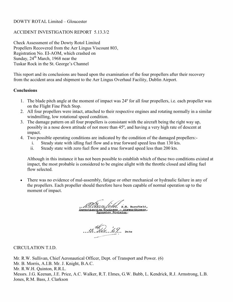
DOWTY ROTAL Limited – Gloucester
ACCIDENT INVESTIGATION REPORT 5.13.3/2
Check Assessment of the Dowty Rotol Limited
Propellers Recovered from the Aer Lingus Viscount 803,
Registration No. EI-AOM, which crashed on
Sunday, 24th
March, 1968 near the
Tuskar Rock in the St. George’s Channel
This report and its conclusions are based upon the examination of the four propellers after their recovery
from the accident area and shipment to the Aer Lingus Overhaul Facility, Dublin Airport.
Conclusions
1. The blade pitch angle at the moment of impact was 24º for all four propellers, i.e. each propeller was
on the Flight Fine Pitch Stop.
2. All four propellers were intact, attached to their respective engines and rotating normally in a similar
windmilling, low rotational speed condition.
3. The damage pattern on all four propellers is consistant with the aircraft being the right way up,
possibly in a nose down attitude of not more than 45º, and having a very high rate of descent at
impact.
4. Two possible operating conditions are indicated by the condition of the damaged propellers:-
i. Steady state with idling fuel flow and a true forward speed less than 130 kts.
ii. Steady state with zero fuel flow and a true forward speed less than 200 kts.
Although in this instance it has not been possible to establish which of these two conditions existed at
impact, the most probable is considered to be engine alight with the throttle closed and idling fuel
flow selected.
There was no evidence of mal-assembly, fatigue or other mechanical or hydraulic failure in any of
the propellers. Each propeller should therefore have been capable of normal operation up to the
moment of impact.
CIRCULATION T.I.D.
Mr. R.W. Sullivan, Chief Aeronautical Officer, Dept. of Transport and Power. (6)
Mr. B. Morris, A.I.B. Mr. J. Knight, B.A.C.
Mr. R.W.H. Quinton, R.R.L.
Messrs. J.G. Keenan, J.E. Price, A.C. Walker, R.T. Elmes, G.W. Bubb, L. Kendrick, R.J. Armstrong, L.B.
Jones, R.M. Bass, J. Clarkson
* Summary Only.
Compiled – R.H. Barnfield
Approved
Dept. – Airworthiness
Date – 27.11.69
1. Details of Propellers Installed on EI-AOM
Type R. 130/4-20-4/12E
Starting Pitch Blade Angle 0º
Flight Fine Pitch Stop Blade Angle 24º
Feathered Blade Angle 84º 24’
Propeller Serial Nos.
Installation Propeller
Serial No.
Hours
T.S.N.
Hours
T.S.O.
Port Outer (No. 1) 130/57/212 14,055.50 2998.50
Port Inner (No. 2) 130/57/218 16,890 3263
Stbd. Inner (No. 3) 130/57/377 15,411.10 1008.10
Stbd. Outer (No. 4) 130/57/287 15,975.10 1559.10
Propeller Blades RA. 25842
Installation Blade No. 1 Blade No. 2 Blade No. 3 Blade No. 4
Port Outer ( No. 1) A.92566* A.92433 A.92723 A.92603
Port Inner (No. 2) A.100725 A.99225 A.99226 A.99251
Stbd. Inner (No. 3) A.93683 A.93792 A.93756 A.93697
Stbd. Outer (No. 4) A.93881 A.93302 A.93904* A.93176
* These two blades have not been recovered.
2. General
2.1 Blade positions are, as viewed from the front of the hub, 1,2,3 and 4 reading clockwise from
No. 1 blade position, and the propeller is left hand tractor when viewed from the rear, i.e.
the sequence of blade rotation is 4,3,2,1
2.2 All blade angles and stop settings in this report refer to the pitch angle at the 0.7 radius
station.
3. Port Outer Propeller (No. 1). Serial No. 130/57/212
3.1 General
3.1.1 No. 1 propeller with a major portion of the engine reduction gear attached, Ref. Plate 1, was
recovered from the main wreckage area approximately four months after the accident.
All the magnesium parts of the reduction gear casing had completely corroded away therefore it was not
possible to establish whether the propeller had broken away from the engine at impact.
3.1.2 Blades Nos. 2, 3 and 4 were retained in the hub but blade No. 1 was detached and has not
been recovered.
3.1.3 The three blades retained in the hub showed with varying degrees of severity similar general
characteristics of axial bending into the pressure face with associated chordal fine pitch
twisting, Ref. Plate 2.
3.1.4 The blade bearing retention threads in the hub port of No. 1 blade were sheared and
damaged around the front of the hub, Ref. Plate 3, but were virtually undamaged at the rear.
3.1.5 Only a small portion of the spinner front shell which was still attached to the centre section
was recovered. The centre section was locally crushed in the region of No. 1 hub arm, but
was relatively undamaged between hub arms Nos. 2, 3 and 4.
3.1.6 The pitch lock mechanism appeared to be undamaged. External seals on the assembly were
in a good condition and the oil was not contaminated, other than by sea water.
3.1.7 There were no significant damage marks in the bore of the main cylinder, on the cylinder
backplate, on the barrel of the transfer sleeve housing or on the eyebolt link and sleeve
assemblies. No. 3 link assembly was intact.
The transfer sleeve housing (which retains the cylinder assembly onto the hub) was
correctly tightened into the hub and the tabs of the locking washer were intact and correctly
located.
3.1.8 The main operating piston, piston liner and pitch stops were undamaged.
3.1.9 The four blade bearing lockpieces were attached to their respective locations on the cylinder
backplate and were intact.
3.1.10 During the dismantling of the propeller, the main operating piston was found in a position
equivalent to a blade angle of approximately 37º.
3.2 Salient features noted during the examination of the Port Outer (No.1) Propeller Blade and
Bearing Assemblies.
3.2.1 No. 1 blade has not been recovered.

3.2.2 No. 2 Blade and Bearing Assembly.
i. Blade
Slight axial bend into pressure face at approximately 60% radius. Those faces of the
blade root dogs normally loaded by a relative fine pitch twisting of the blade heavily
indented, distorted and cracked.
ii. Bearing Assembly
Roller witness indentations on a section of the preload tracks with the major axis of damage
approximately 210º measured in a clockwise direction from the front of the hub. A visual
matching of these roller indentations established the blade angle to have been approximately
11º when they were produced.
The operating pin retaining bolts and dowel located in the bearing C.F. race had failed due
to overloads produced by a relative fine pitch twisting and rearwards tilting of the blade.
3.2.3 No. 3 Blade and Bearing Assembly.
i. Blade
Axial bend through approximately 30º into pressure face at 45% radius. Light
indentations on the faces of the blade root dogs normally loaded by relative fine
pitch twisting of the blade.
ii. Bearing Assembly
Light roller witness indentations on blade bearing tracks. A more detailed analysis of these
roller indentations was performed at Dowty Rotol Limited – Ref. Appendix 1, to establish
pitch angle at impact.
Operating pin attached to bearing C.F. race.
3.2.4 No. 4 Blade and Bearing Assembly
i. Blade
Pronounced smooth axial bend along length of blade through approximately 120º
into pressure face with associated chordal fine pitch twist. Those faces of the blade
root dogs normally loaded by a relative fine pitch twisting of the blade heavily
indented, distorted and cracked.
ii. Bearing Assembly
No significant roller witness indentations on the tracks of either the preload or C.F. races.
The operating pin retaining bolts and dowel located in the bearing C.F. race failed in shear
due to overloads produced by relative fine pitch twisting and rearwards tilting of the blade.
3.3 General Analysis – Port Outer Propeller (No. 1)
3.3.1 The general pattern of axial bending into the pressure face with associated chordal fine pitch
twisting, exhibited by all three blades retained in the propeller hub, is characteristic of
damage produced by impact loads on a windmilling propeller.
The pattern of bending and twisting of No. 4 blade, with no evidence of its having hit other
structures, is consistent with the deformation having been produced by heavy hydro-
dynamic loads such as would be encountered by a rotating blade being suddenly and totally
submerged in water.
3.3.2 The pattern of damaged blade bearing retention threads in hub port No. 1 and the condition
of the blade bearing lock piece is consistent with No. 1 blade having been pulled out of the
hub by a rearwards bending of the blade, and is indicative of a high propeller Advance
Ratio, i.e. a low rotational speed relative to forward velocity. This feature is also consistent
with a windmilling condition.
3.3.3 The relatively undamaged condition of the spinner centre section between Nos. 3 and 4
blades is indicative of negligible propeller rotation after initial impact, suggesting low
rotational energy.
3.3.4 The linkage of No. 2 blade ruptured at impact. The equivalent blade angle of 11º evaluated
from the roller witness marks on the tracks of the bearing therefore does not reflect blade
angle at initial impact but only confirms that impact loads twisted the blade fine. (That
significant changes in blade angle can occur before blade bending loads transmitted through
the bearing rollers can produce witness indentations is an observed and established feature
when blade linkage is broken)
However the linkage of blade No. 3 had remained intact and by comparing bearing race
distortion, the individual depth of roller indentations and their respective positions using a
Rank Taylor Hobson Talyrond, it was possible to establish the pitch angle of the blade was
24º at impact. Ref. Appendix No. 1.
3.3.5 The position of the main operating piston as found during dismantling is not considered, by
itself, to be an indication of blade angle at impact. In this propeller particularly, blade angle
at impact is believed to have been correctly derived from No. 3 blade bearing, and the
variance between this angle and the angle obtained from piston position is considered to
have been due to subsequent movement of the piston after impact. This movement could
have been caused by hydro-dynamic loads turning blade 3 after impact, or could have
occurred during recovery and transport operations.
3.3.6 There was no evidence of mal-assembly or pre – crash or pre-crash mal-functioning in the
propeller.

4. Port Inner Propeller (No. 2). Serial No. 130/57/218
4.1 General
4.1.1 No. 2 Propeller with the whole of the reduction gear attached (Ref. Plate 4) was recovered
from the main wreckage area approximately four months after the accident. The condition
of the reduction gear and casings was very similar to those of propeller No. 1 and likewise it
was not possible to establish whether the propeller had broken away from the engine at
impact.
4.1.2 Blades Nos. 2, 3 and 4 were retained in the hub, but blade No. 1 was detached and was
recovered approximately five months after the accident.
4.1.3 The three blades retained in the hub showed similar damage to those of propeller No. 1,
namely general characteristics of axial bending into the pressure face with associated
chordal fine pitch twisting, Ref. Plate 5.
No. 1 blade also showed these characteristics, but in addition had sustained damage to the
leading edge, caused by the blade apparently striking other wreckage debris.
4.1.4 The blade bearing retention threads in the hub port of No. 1 blade were sheared and
damaged around the front of the hub but were virtually undamaged at the rear, similar to
No. 1 hub port of No. 1 propeller. In addition there were two clearly impressed witness
marks of the blade bearing spanner location dogs on the top face of the hub port at the rear.
4.1.5 The spinner front shell was detached from the centre section and not recovered. The centre
section was locally severely crushed in the region of No. 1 hub arm.
4.1.6 The transfer sleeve housing was detached from the hub centre, although the tabs of the
locking washer were intact and correctly located. Maximum thread damage was adjacent to
the No. 1 hub arm position. There were no markings on the housing barrel.
4.1.7 The spinner abutment flange on the main operating cylinder was broken by rearwards
bending in line with No. 1 hub arm. There were no other significant markings in the
cylinder or on the cylinder backplate.
4.1.8 The pitch lock mechanism appeared to be undamaged. Visible seals on the assembly were in
a good condition and the oil was not contaminated, other than by sea water.
The main operating piston, piston liner and pitch stops were undamaged, but there was local
staining on the flight fine pitch stop from contact with the spring collet fingers in line with
No. 4 eyebolt.
4.1.9 The four blade bearing lock pieces were undamaged and correctly attached to the cylinder
backplate.

4.1.10 During the dismantling of the propeller the main operating piston was found in a position
equivalent to a blade angle of 24º
4.2 Salient Features noted during the examination of the Port Inner (No.2) Propeller Blade,
Bearing and Link Assemblies.
4.2.1 No. 1 Blade, Bearing and Link Assembly
i. Blade
Axial bend through approximately 60º into the pressure face at 35% radius with an
associated chordal fine pitch twist. Pronounced curl of leading edge section of blade
into pressure face, (i.e. fine pitch twist) outboard from 75% radius with an associated
severe scuffing on the suction face. Leading edge severely damaged between 30%
and 75% radius.
ii. Bearing and Link Assembly
The retaining bolts securing the operating pin to the C.F. bearing race had failed in overload
produced by fine pitch twisting and rearwards tilting of the blade.
4.2.2 No. 2 Blade, Bearing and Link Assembly
i. Blade
Slight axial bend into pressure face at approximately 40% radius. Light indentations
on the faces of the blade root dogs normally loaded by relative fine pitch twisting of
the blade.
ii. Bearing Assembly
Visual correlation of light roller witness indentations on the tracks of the preload
races showed the blade to have been in a negative pitch when the indentations were
produced.
4.2.2 iii. Link Assembly
Operating pin attached to the bearing C.F. race but the locating dowel sheared by a relative
fine pitch twisting – rearwards tilting of the blade.
No significant marks on the eyebolt link but the skirts at the rear end of the sleeve slightly
deformed.

4.2.3 No. 3 Blade, Bearing and Link Assembly
i. Blade
Axial bend through approximately 30º into pressure face at 40% radius with an
associated chordal fine pitch twist.
ii. Bearing Assembly
Very light roller witness indentations on the tracks of the preload races.
iii. Link Assembly
Operating pin attached to the bearing C.F. race but the locating dowel distorted by a relative
fine pitch twisting – rearwards tilting of the blade.
Shank of the eyebolt link fractured by bending overload near the big end locating the
operating pin. Associated damage witness marks on the rear skirt of the eyebolt guide bush.
4.2.4 No. 4 Blade, Bearing and Link Assembly
i. Blade
Axial bend through approximately 135º into pressure face between 40% and 60%
radius with an associated chordal fine pitch twisting.
Those faces of the blade root dogs normally loaded by a relative fine pitch twisting
of the blade all sheared.
ii. Bearing Assembly
Deep roller witness indentations on the tracks of the preload races. A visual
matchcing of these indentations established the blade angle to have been 24º when
they were produced.
iii. Link Assembly
The retaining bolts and locating dowel securing the operating pin to the bearing C.F.
race sheared by relative fine pitch twisting and rearward tilting. of the blade.
4.3 General Analysis – Port Inner Propeller (No.2)
4.3.1 The general pattern of axial bending into the pressure face with associated chordal fine pitch
twisting exhibited by all four blades and their link assemblies is characteristic of damage
produced by impact loads on a windmilling propeller.
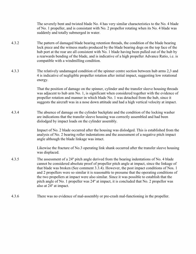
The severely bent and twisted blade No. 4 has very similar characteristics to the No. 4 blade
of No. 1 propeller, and is consistant with No. 2 propellor rotating when its No. 4 blade was
suddenly and totally submerged in water.
4.3.2 The pattern of damaged blade bearing retention threads, the condition of the blade bearing
lock piece and the witness marks produced by the blade bearing dogs on the top face of the
hub port at the rear are all consistent with No. 1 blade having been pulled out of the hub by
a rearwards bending of the blade, and is indicative of a high propeller Advance Ratio, i.e. is
compatible with a windmilling condition.
4.3.3 The relatively undamaged condition of the spinner centre section between hub arms 2,3 and
4 is indicative of negligible propeller rotation after initial impact, suggesting low rotational
energy.
That the position of damage on the spinner, cylinder and the transfer sleeve housing threads
was adjacent to hub arm No. 1, is significant when considered together with the evidence of
propeller rotation and manner in which blade No. 1 was detached from the hub, since it
suggests the aircraft was in a nose down attitude and had a high vertical velocity at impact.
4.3.4 The absence of damage on the cylinder backplate and the condition of the locking washer
are indications that the transfer sleeve housing was correctly assembled and had been
dislodged by impact loads on the cylinder assembly.
Impact of No. 2 blade occurred after the housing was dislodged. This is established from the
analysis of No. 2 bearing roller indentations and the assessment of a negative pitch impact
angle although the blade linkage was intact.
Likewise the fracture of No.3 operating link shank occurred after the transfer sleeve housing
was displaced.
4.3.5 The assessment of a 24º pitch angle derived from the bearing indentations of No. 4 blade
cannot be considered absolute proof of propeller pitch angle at impact, since the linkage of
that blade was broken (See comment 3.3.4). However, the post impact conditions of Nos. 1
and 2 propellers were so similar it is reasonable to presume that the operating conditions of
the two propellers at impact were also similar. Since it was possible to establish that the
pitch angle of No. 1 propeller was 24º at impact, it is concluded that No. 2 propellor was
also at 24º at impact.
4.3.6 There was no evidence of mal-assembly or pre-crash mal-functioning in the propeller.

5.1 General
5.1.1 No. 3 propeller with part of the engine reduction gear attached, Ref. Plate 6, was recovered
from the main wreckage area approximately seventeen months after the accident. All the
magnesium parts of the reduction gear casing had completely corroded away as with No. 1
propeller and likewise it was not possible to establish whether the propeller had broken
away from the engine at impact.
5.1.2 All four blades were retained in the hub and showed with varying degrees of severity
similar general characteristics of axial bending into the pressure face with associated
chordal fine pitch twisting.
5.1.3 The spinner front shell was detached from the centre section and was not recovered. The
centre section was locally severely crushed in the region of Nos. 3 and 4 hub arms, Ref.
Plate 7, and was relatively undamaged in the region of No. 1 hub arm.
The lower half of the engine mounted brush gear housing had broken away and was not
recovered.
5.1.4 Some of the aluminium alloy components of the propeller operating mechanism had been
affected by salt water corrosion, the main operating cylinder being the most severely
affected with a large section of the barrel having corroded away, Ref. Plate 7. Locally in this
region of the cylinder there was also evidence of longitudinal cracks.
5.1.5 The pitch lock mechanism appeared to be undamaged other than from the affects of salt
water corrosion. Visible seals were in a good condition.
5. Starboard Inner Propeller (No. 3). Serial No. 130/57/377.
Corrosion patterns on the abutment faces of the spring collet fingers and the flight fine pitch
stop showed these components to have been in contact whilst the propeller was submerged,
i.e. at this stage the propeller was on the flight fine pitch stop at 24º.
5.1.6 There were no significant damage marks on the cylinder back-plate, on the barrel of the
transfer sleeve housing or on the eyebolt link and sleeve assemblies.
The transfer sleeve housing, (which retains the cylinder assembly onto the hub), was
correctly tightened into the hub and the tabs of the locking washer were intact and correctly
located.
5.1.7 The main operating piston, piston liner and pitch stops were undamaged other than from salt
water corrosion.
5.1.8 During the dismantling of the propeller, the main operating piston was found in a position
equivalent to a blade angle of 24º.

5.2 Salient features noted during the examination of the Starboard Inner (No. 3) Propeller Blade
and Bearing Assemblies.
5.2.1 No. 1 Blade and Bearing Assembly
i. Blade
Slight axial bend into pressure face at approximately 35% radius with an associated
chordal fine pitch twist. This blade was not taken out of the hub during dismantling.
ii. Bearing Assembly
Not dismantled. Operating pin attached to bearing C.F. race.
5.2.2 No. 2 Blade and Bearing Assembly
i. Blade
Pronounced axial bend into pressure face at approximately 40% radius with
associated chordal fine pitch twisting extending outwards towards the tip.
ii. Bearing Assembly
Not dismantled. The retaining bolts securing the operating pin to the bearing C.F. race had
failed in overload produced by fine pitch twisting and rearwards tilting of the blade.
5.2.3 No. 3 Blade and Bearing Assembly
i. Blade
Axial bend through approximately 90º along the length of the blade into pressure
face with associated chordal fine pitch twisting. Leading edge severely damaged
between 30% and 75% radius.
Those faces of the blade root dogs normally loaded by fine pitch twisting of the
blade all sheared.
ii. Bearing Assembly
Blade askew in bearing due to rollers trapped between preload race thrust rib and centre
race. Relative positions of the indentations produced by these trapped rollers show that
during impact the blade twisted into a negative pitch.
A visual matching of deep roller witness indentations on the tracks of the preload races

show the blade angle to have been 24º when they were produced.
Very light roller witness indentations on tracks of C.F. races.
The retaining bolts securing the operating pin to the bearing C.F. race had failed in overload
produced primarily by rearwards tilting of the blade.
5.2.4 No. 4 Blade and Bearing Assembly
i. Blade
Pronounced axial bend into pressure face along length of blade with an associated
chordal fine pitch twist. Slight damage on Leading Edge.
ii. Bearing Assembly
Visual correlation of deep roller witness indentations on the tracks of the preload races
showed the blade had twisted fine at impact.
The operating pin retaining bolts and dowel located in the bearing C.F. race had failed due
to overloads produced by relative fine pitch twisting and rearwards tilting of the blade.
5.3 General Analysis – Starboard Inner Propeller (No. 3)
5.3.1 The general pattern of axial bending into the pressure face with associated chordal fine pitch
twisting exhibited by all four blades is very similar to the pattern of damage on the blades of
Nos. 1 and 2 propellers; namely is characteristic of damage produced by hydro-dynamic
loads on a windmilling propeller. That No.1 blade was relatively lightly damaged would
suggest a low rotational energy.
5.3.2 Whereas one blade had been pulled out of its hub arm on each of Nos. 1 and 2 propellers, all
the blades had been retained in No. 3 propeller hub. The reason for No. 3 propeller
remaining intact may be due to a more even distribution of impact loads between the Nos. 3
and 4 blades, the individual loads being insufficient to wrench either blade out of hub but
nevertheless being large enough to displace the blades in their bearing assemblies. The
severe damage evident on the preload tracks of these bearing would suggest that only a
small increase in bending loads would have pulled one or other blade out of the hub.
5.3.3 The pattern of damage on the spinner centre section relative to the severely damaged Nos. 3
and 4 blades, is consistent with a rapid submersion in less than one propeller revolution.
This indicates a high vertical velocity, which from the locally relatively undamaged
condition of the spinner centre section adjacent to No. 1 hub arm could be associated with
an aircraft nose down attitude of not more than 45º.
5.3.4 From the damage pattern on the brush gear housing which is mounted on the engine
reduction gear front cover it is evident that the aircraft was the right way up at impact, as the
damage was on the underside of the housing.

5.3.5 It can be argued that the blade angle of 24º computed from the relative positions of the roller
indentations of No. 3 blade bearing need not necessarily have been the blade angle at
impact, since the blade linkage was broken. (See comment 3.3.4). However the general
damage to Nos. 1, 2 and 3 propellers was so similar it would be reasonable to suppose that
the three propellers were operating at similar conditions at impact.
It is therefore concluded that the blade angle of No. 3 propeller was 24º at impact.
5.3.6 There was no evidence of mal-assembly or pre-crash mal-functioning in the propeller.

6.1 General
6.1.1 No 4 propeller with an almost complete engine reduction gear attached, Ref. Plate 8, was
recovered from the main wreckage area less than three months after the accident. The
magnesium points of the reduction gear casing had not completely disintegrated, and the
propeller with the reduction gear was attached to No. 4 engine when the power plant was
located on the sea bed.
6. Starboard Outer Propeller (No. 4). Serial No. 130/57/287
6.1.2 Blades Nos. 1, 2 and 4 were retained in the hub, but blade No. 3 was detached and has not
been recovered.
6.1.3 The three blades retained in the hub showed a similar pattern of damage to those blades
retained in the hubs of Nos. 1,2 and 3 propellers, namely general characteristics of axial
bending into the pressure face with associated chordal fine pitch twisting.
6.1.4 The blade bearing retention threads in the hub port of No. 3 blade were sheared and
damaged around the front of the hub but were virtually undamaged at the rear, similar to
No. 1 hub ports of Nos. 1 and 2 propellers. In addition there were three clearly impressed
witness marks of the blade bearing spanner location dogs on the top face of the hub port at
the rear.
6.1.5 Rather less than half of the spinner front shell was recovered with the propeller. This portion
of spinner had been closely moulded around the cylinder, front cover and retaining nut.
The spinner centre section was locally crushed in the region of No. 3 hub arm but was
relatively undamaged between hub arms Nos. 1,2 and 4.
6.1.6 The pitch lock mechanism appeared to be undamaged. External seals on the assembly were
in a good condition and the oil was clean.
6.1.7 The spinner abutment flange on the main operating cylinder and the spinner backplate were
broken by rearwards bending in line with No. 3 hub arm. There were no other significant
markings in the cylinder or on the cylinder backplate.
6.1.8 The lower half of the engine mounted brush gear housing was broken.
6.1.9 The main operating piston and piston liner were undamaged, but witness marks matching
with the abutment faces of the spring collet fingers were evident on the flight fine pitch
stop.
6.1.10 The four blade bearing lock pieces were undamaged and correctly attached to the cylinder
backplate.
6.1.11 During the dismantling of the propeller, the main operating piston was found in a position
equivalent to a blade angle of 24º.

6.2 Salient features noted during the examination of the Starboard Outer (No. 4) Propeller
Blade, Bearing and Link Assemblies.
6.2.1 No. 1 Blade, Bearing and Link Assembly
i. Blade
Slight axial bend into pressure face at approximately 30% radius with an associated
chordal fine pitch twist.
ii. Bearing Assembly
Not dismantled.
iii. Link Assembly
The retaining bolts securing the operating pin to the bearing C.F. race had failed in overload
produced by fine pitch twisting and rearwards tilting of the blade.
No significant marks on operating pin, link and eyebolt sleeve.
6.2.2 No. 2 Blade, Bearing and Link Assembly
i. Blade
Axial bend through approximately 90º along the length of the blade into the pressure
face with an associated chordal fine pitch twist, particularly on the leading edge at
the tip.
ii. Bearing Assembly
No significant damage to the tracks
iii. Link Assembly
The retaining bolts securing the operating pin to the bearing C.F. race had failed in overload
produced by fine pitch twisting and rearwards tilting of the blade.
No significant marks on operating pin, link and eyebolt sleeve.
6.2.3 No. 3 Blade, Bearing and Link Assembly
i. Blade and Bearing Assembly
Not recovered
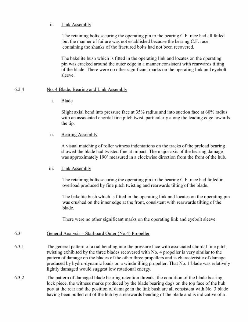
ii. Link Assembly
The retaining bolts securing the operating pin to the bearing C.F. race had all failed
but the manner of failure was not established because the bearing C.F. race
containing the shanks of the fractured bolts had not been recovered.
The bakelite bush which is fitted in the operating link and locates on the operating
pin was cracked around the outer edge in a manner consistent with rearwards tilting
of the blade. There were no other significant marks on the operating link and eyebolt
sleeve.
6.2.4 No. 4 Blade, Bearing and Link Assembly
i. Blade
Slight axial bend into pressure face at 35% radius and into suction face at 60% radius
with an associated chordal fine pitch twist, particularly along the leading edge towards
the tip.
ii. Bearing Assembly
A visual matching of roller witness indentations on the tracks of the preload bearing
showed the blade had twisted fine at impact. The major axis of the bearing damage
was approximately 190º measured in a clockwise direction from the front of the hub.
iii. Link Assembly
The retaining bolts securing the operating pin to the bearing C.F. race had failed in
overload produced by fine pitch twisting and rearwards tilting of the blade.
The bakelite bush which is fitted in the operating link and locates on the operating pin
was crushed on the inner edge at the front, consistent with rearwards tilting of the
blade.
There were no other significant marks on the operating link and eyebolt sleeve.
6.3
General Analysis – Starboard Outer (No.4) Propeller
6.3.1 The general pattern of axial bending into the pressure face with associated chordal fine pitch
twisting exhibited by the three blades recovered with No. 4 propeller is very similar to the
pattern of damage on the blades of the other three propellers and is characteristic of damage
produced by hydro-dynamic loads on a windmilling propeller. That No. 1 blade was relatively
lightly damaged would suggest low rotational energy.
6.3.2 The pattern of damaged blade bearing retention threads, the condition of the blade bearing
lock piece, the witness marks produced by the blade bearing dogs on the top face of the hub
port at the rear and the position of damage in the link bush are all consistent with No. 3 blade
having been pulled out of the hub by a rearwards bending of the blade and is indicative of a
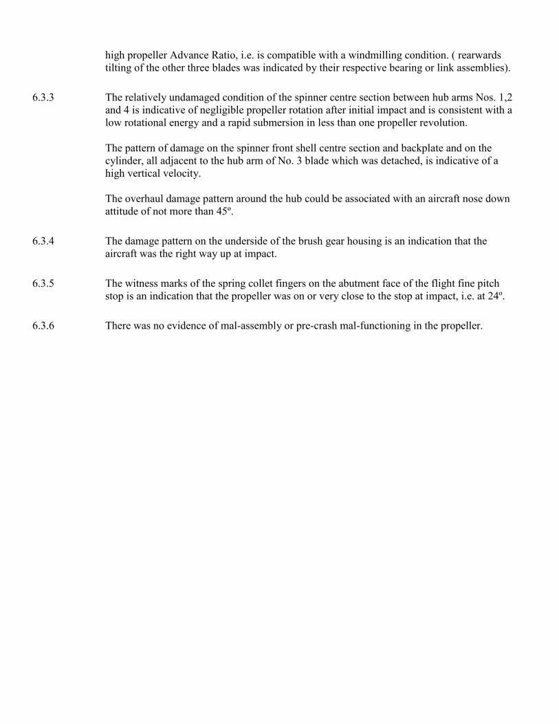
high propeller Advance Ratio, i.e. is compatible with a windmilling condition. ( rearwards
tilting of the other three blades was indicated by their respective bearing or link assemblies).
6.3.3 The relatively undamaged condition of the spinner centre section between hub arms Nos. 1,2
and 4 is indicative of negligible propeller rotation after initial impact and is consistent with a
low rotational energy and a rapid submersion in less than one propeller revolution.
The pattern of damage on the spinner front shell centre section and backplate and on the
cylinder, all adjacent to the hub arm of No. 3 blade which was detached, is indicative of a
high vertical velocity.
The overhaul damage pattern around the hub could be associated with an aircraft nose down
attitude of not more than 45º.
6.3.4 The damage pattern on the underside of the brush gear housing is an indication that the
aircraft was the right way up at impact.
6.3.5 The witness marks of the spring collet fingers on the abutment face of the flight fine pitch
stop is an indication that the propeller was on or very close to the stop at impact, i.e. at 24º.
6.3.6 There was no evidence of mal-assembly or pre-crash mal-functioning in the propeller.

7. Summary and discussion of Results of Examination
7.1 The majority of the damage on the four propellers was by hydro-dynamic loading, although
the detached blade No. 1 from No. 2 propeller and No. 3 blade of No. 3 propeller had both also
been severely damaged by structural impact.
The chordal fine pitch twisting induced in the blades by the Impact loads is indicative that all
the propellers were operating at negative aerodynamic incidence, i.e. that all four propellers
were windmilling at impact.
The general damage pattern, indicative of low rotational energy was remarkably similar on all
four propellers, although one blade had been detached from each of Nos. 1,2 and 4 propellers
at impact whereas all four blades were retained in the hub of propeller No. 3
This discrepancy is considered to be of no significance and is attributed to slight differences in
the distribution of impact loads on the propeller blades.
7.2 If it is postulated that one blade pulled out of its hub in flight, then an entirely different
damage pattern to that found would have been produced in the hub port associated with that
blade and the resultant out of balance forces would have detached the propeller from the
engine. The subsequent propeller impact damage would have been entirely different to that on
the propellers remaining attached to the engines.
Similarly if there had been a propeller disconnect and separation from the engine, an entirely
different damage pattern would have resulted.
All four propellers are therefore considered to have been intact, attached to the engines,
rotating and at the same operating condition at impact.
Although specific evidence of impact blade angle was obtained on only Nos. 1 and 4
propellers, it is believed that all four propellers were at the same pitch angle and on the Flight
Fine Pitch Stop (24º) at impact.
7.3 The damage on the underside of the engine mounted Nos. 3 and 4 brush gear housings shows
the aircraft was the correct way up at impact, and the close angular relationship between the
first blade or blades to impact and the damage on the spinners, which was particularly
noticeable on all four propellers, is indicative of a high vertical velocity. The damage on the
spinners could be consistent with an aircraft nose down attitude of not more than 45º.
7.4 One of two possible operating conditions could be indicated by the foregoing conclusions:-
i. A steady state condition with idling fuel flow.
ii. A steady state condition with zero fuel flow.
It is not possible to ascertain from the condition of the propellers whether in fact the engines
were alight. Consideration has therefore been given to evaluating propeller performance with
idling fuel flow (approximately 275 lb/hr.) and zero fuel flow. For the purpose of these
calculations forward speed is considered to be that producing an air flow normal to the
propeller disc. The vertical component will not significantly affect the mean performance of
the propeller.

The attached graph NO. H.0213 shows the values of windmilling drag and engine revs/min. Vs
forward speed for 10,400 selected engine revs/min. for I.S.A. Sea Level conditions with
approximately 275 lb/hr. and zero flow.
Graph No. H0213
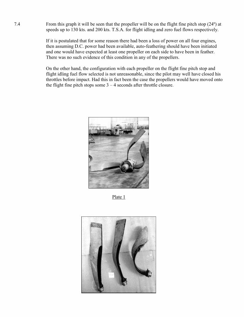
7.4 From this graph it will be seen that the propeller will be on the flight fine pitch stop (24º) at
speeds up to 130 kts. and 200 kts. T.S.A. for flight idling and zero fuel flows respectively.
If it is postulated that for some reason there had been a loss of power on all four engines,
then assuming D.C. power had been available, auto-feathering should have been initiated
and one would have expected at least one propeller on each side to have been in feather.
There was no such evidence of this condition in any of the propellers.
On the other hand, the configuration with each propeller on the flight fine pitch stop and
flight idling fuel flow selected is not unreasonable, since the pilot may well have closed his
throttles before impact. Had this in fact been the case the propellers would have moved onto
the flight fine pitch stops some 3 – 4 seconds after throttle closure.
Plate 1
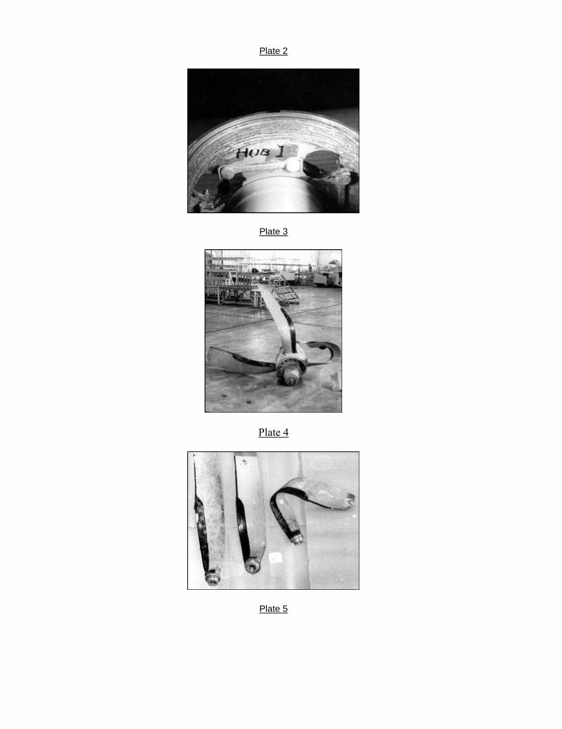
Plate 2
Plate 3
Plate 4
Plate 5
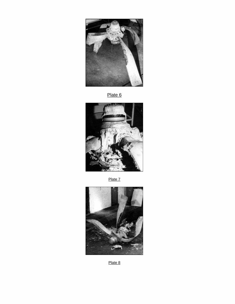
Plate 6
Plate 7
Plate 8

APPENDIX 1
Analysis of roller indentation postions on a blade
bearing preload and centre race fitted to a Type R.130 propeller,
Serial No. 130/57/212
Identification
Preload Race RA. 59401 Serial No. 16134/R
Centre Race RA. 59400 Serial No. 16134/R
Introduction
The two races were part of the bearing assembly fitted to blade NO. 3 Serial No. A.92723 of No. 1 propeller
Serial No. 130/57/212 installed on the Aer Lingus Viscount EI-AOM which crashed in the St. George’s
Channel on 24th
March, 1968. The races were returned to Dowty Rotol Limited for assessment of the blade
angle at impact.
Conclusions
An equivalent blade angle of 24º 24’ is obtained by using the etched reference marks and from matching the
indentations on the bearing preload and centre races.
Since the etched reference marks were aligned ‘by eye’, it is concluded that the propeller was on the Flight
Fine Pitch Stop (24º) at impact.
Details of Examination
1. Reference marks had been etched on each race during dismantling of the propeller, showing the
relative positions of the blade operating pin to the preload race and the front of the hub to the centre
race.
2. Bearing race distortion, the individual depths of roller indentations and the positions relative to the
reference marks on the races were measured using a Rank-Taylor-Hobson Talyrond. The resultant
plots are shown on Fig. 1.
3. To correlate the indentations, the trace obtained from the preload race must be considered as a mirror
image. A graphical interpretation of the results is shown on Fig. 2.
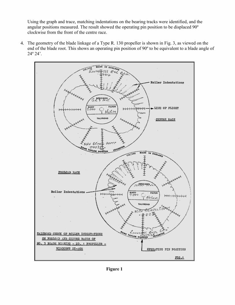
Using the graph and trace, matching indentations on the bearing tracks were identified, and the
angular positions measured. The result showed the operating pin position to be displaced 90º
clockwise from the front of the centre race.
4. The geometry of the blade linkage of a Type R. 130 propeller is shown in Fig. 3, as viewed on the
end of the blade root. This shows an operating pin position of 90º to be equivalent to a blade angle of
24º 24’.
Figure 1

Figure 2
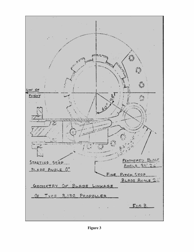
Figure 3

Appendix 5
Examination of S.E.P.2. Autopilot
5.1 An examination of components of the autopilot – a Smiths S.E.P.2 was done at Dublin Airport on 21st
October, 1968.
1. Heading Selector Code No. ISMT
Mod. No. 1
The Serial No. of this item from the aircraft records was 1125, however the Serial No. engraved
on the dial was 2127A.
The Compass Card was reading 65º and the Select Heading Pointer was set at 120º. The
instrument was badly damaged and both the above indications were frozen. It is considered that
these were the positions of the two indications at impact. No other evidence was obtained from
this instrument.
2. Flight Panel Code No. 245.EAP
Serial No. 1099/57
The three channel switches were switched ‘in’ and the contacts were closed. The Power Height
Lock, Beam and Glide switches were in the off position but were free to operate and would
have relaxed to the 'off’ position when the power supply was lost. The Pitch Switch was central
but was free to be moved. The Turn Control was fully clockwise but was not frozen in this
position. The ‘Ready’ light bulb was removed for examination but evidence of lighting at
impact inconclusive.
3. Safety Switching Unit Code No. 270.EAP
The data plate had been damaged and the Serial No. obliterated.
The relays were extensively damaged and no useful evidence could be obtained.
4. Heading Control Unit Code No. 230.EAP
Serial No. 1125 Mod. Nos. 1 & 2
This item was contaminated due to exposure to the sea water. The fuses were intact.
5. Aileron Servomotor.
The only part of this item recovered was the MK. 4 Plug & Socket with a section of aircraft
cable identified J11 and a number of internal Servomotor leads attached to the socket. The ends
of three of these leads (pins K,M and C) had globules on their extreme ends.

These had originally been diagnosed as fusing which had occurred when the leads were torn
from the Servomotor with power on. Further microscopic examination however showed that
they were in fact the soldered joints where the leads had been connected to the windings of the
motor and generator.
Engage and Trim Indicator
The trim movement was missing and the Engage Flags were broken away from the movements.
Only one flag was found. No useful evidence was noted.
7. Trim Servo Motor Code No. 259.EAP
Serial No. 1100/57
The Clutch assembly was in a satisfactory condition. The clutch, motor and brake were
electrically in a satisfactory condition. Although the assembly had suffered some corrosion due
to exposure to the sea water, there was no evidence of pre-crash damage.
8. Amplifier Unit Code No. 275.EAP
Serial No. 1115
This item had been extensively damaged and only certain items were in a condition which
warranted further examination.
a. Link Panel
This was in a reasonable condition, all the links were present apart from PR but there
was evidence that this had been torn out of the 0.6 position. It was determined that the
links were in the correct positions for the aircraft type.
b. Balance Potentiometers
The CF potentiometer was broken but the others were set as follows:
Rudder + 1 ½
Aileron - ½
Elevator - 1
c. Cooling Fan
The motor and fan runner were intact but the fan case moulding was broken. Where the
case had been crushed on to the fan runner the fan blade ends had marked the moulding.
The marks were in a form which showed that when the case crushed, the fan runner had
been rotating.
d. Pitch Datum Potentiometer
Code No. HM20/2 Serial No. 621/6172
When the contact plate was removed the interior of the potentiometer was in a clean and
dry condition but the internal components were not in their normal position. During a
continuity check of the potentiometer the winding was satisfactory but the wiper contact
was open circuit for approximately one third of the travel from the anti-clockwise (nose
down) end. The other two thirds of the travel were giving intermitted contact. One slip
ring contact of the wiper plate EAP 6403 was bent down to a point where it would not
make contact with the slip ring EAP 604.
The other slip ring contact was incorrectly formed and lifted so that it would have
excessive pressure on the slip ring. The outer turn of the anti-backlash spring HSC.2832
was deformed radically. The three contact wiper wires were not lying in line with each
other and the tail of the wiper plate to which they are attached was bent down onto the
moulding EAP.6441/M. The deformation of the wiper wires and plate had caused the
loss of wiper contact pressure.
There were three sets of contact tracks on the potentiometer winding face. One set was
in the centre of the track where the wipers would contact if correctly set up. The other
two tracks were either side of the normal track and lined up with the deformed contact
wiper positions.
It was considered that the deformation of the slip ring contacts and the anti-backlash
spring would have no detrimental effect on the pitch datum motor operation. It was also
agreed that this deformation could not have been caused during impact.
The deformation of the wiper wires was also considered to have occurred pre-impact
but it was considered that the bend in the tail of the wiper plate may have occurred due
to impact forces. Smiths Industries Limited carried out acceleration tests on a Pitch
Datum Potentiometer. It was subjected to acceleration tests by two methods to
determine the effects of excessive "g" loading on the potentiometer components. The
wiper assembly was set so that the acceleration would act in a direction to bend the tail
of the wiper plate as noted on the crash item. The P.D.M. was subjected to an
acceleration test of 150g on a pneumatic cylinder decelerator giving a sinusoidal wave
form. The wiper assembly was examined and no deformation had occurred. This test
was followed by two further acceleration tests of 22g on a lead block decelerator giving
a square wave pulse. Further examination showed that no deformation had occurred.
c. Pitch Datum Motor and Gearbox
The assembly was corroded due to exposure to sea water. The head of one of the screws which
hold the gear box in the motor was missing allowing the flange joint to open. The gear box
interior was severely corroded and as the head of the screw was not found it may have been
removed by the action of the salt water. There was no evidence of pre-impact damage.

EFFECT OF A COMPLETE OPEN CIRCUIT P.D.M. POTENTIOMETER ON AUTOPILOT
PERFORMANCE.
Although the contact in the P.D.M. was intermittent the worst case of a complete open circuit was
considered under the various autopilot operating modes:
1. Autopilot disengaged.
The action of the Mercury Switch to ‘level’ the Pitch Platform would tend to be not quite as precise as
designed but the degree of malfunction would be virtually negligible in its effect.
2. Autopilot Engaged.
As the Autopilot was engaged, the prevailing pitch attitude of the aircraft could be affected by 1
above to the extent that it would be gently altered in one direction until the Gyro Pitch Platform
became ‘level’. This, therefore, would be immediately reflected on the Rate of Climb indicator and
the Pilot would use his Pitch Control to trim out to requirements. In using the Pitch Control,
however, some sloppiness in achieving the desired pitch attitude would undoubtedly become
apparent, because the nature of the fault under consideration deprives the pitch manoeuvring system
of any precise ‘position’ control, and there would also be a tendency for the pitch rates on the ‘slow’
and ‘fast’ positions of the Pitch Control knob to be higher than normal.
3. Aircraft on climb-out under Autopilot control at 160 kts. IAS And 1000 ft/min. rate of climb –
Height lock selected at 17000 ft.
In addition to depriving the Autopilot pitch manoeuvring system of any ‘position’ control, as
previously stated, the fault under review would also inhibit operation of the Height Integrator
Amplifier when Height Lock mode was engaged.
Under the flight conditions stated above, therefore, the first affect of the height error signal being
developed would be to drive the Gyro Platform at a speed proportional to its magnitude to return the
aircraft towards the ‘selected’ altitude. Therefore, however, because of the lack of height error
integration, there would be no subsidence of the aircraft onto the ‘selected’ height, but passage
through it and initiation of Autopilot pitch control in the opposite direction. In other words a Height
Lock oscillation would develop.
Without resort to special calculations using the aircraft derivatives, etc. it is not possible to predict
exactly the subsequent nature of this phugoid motion. Nevertheless, neglecting the inertia effects of
the aircraft and assuming that the Pitch Platform Amplifier always drives the gyro Pitch Platform at
its maximum speed of 2.5º/sec. (nominal) for corrective action, then under these extreme conditions
it is possible to show that the resultant Autopilot control would be to try and make the aircraft
execute a pitch oscillation of 4.4 sec. Period with normal acceleration increments of +0.48 g being
applied.
Quite obviously the aircraft would not behave like this in practice and, even if it could, it would not
be catastrophic. At this stage, therefore, only the following carefully considered prediction can be
offered.
The imposed oscillatory pitch motion would be initially milder than that quoted above but become
slowly divergent. Without any doubt, therefore, the resultant effects of this on pitch attitude, airspeed
and rate-of-climb, together with the induced ‘g’ increments, would thereafter alert any Pilot to take
perfectly safe and short-term corrective action. It is also considered that, failing ‘instinctive’
disengagement of the Autopilot by the Pilot, the resultant change of trim being experienced by the
Autopilot Elevator Servomotor would, in itself, very shortly effect an automatic ‘cut out’ via the
Rotary Torque Limitor on this channel especially if the order of ± 0.5g increments were being
incurred. (Note: The Automatic Alevator Trim System is ‘lagging’ and therefore assisting in this
effect). Any reaction of the Pilot to try and ‘override’ the Autopilot by appropriate action on the
Control Column would also produce equivalent results.
4. (a) Aircraft on climb-out under Autopilot control at 160 kts. I.A.S. and 1000 ft/min Rate-of-climb –
Height Lock selected at 1000 feet.
(b) Height error signal always causes pitch platform to run at 2.5º/sec (nominal maximum) until
either,
i. Platform reaches limit ( 15º from level flight), or
ii. Height error reverses sign, in which case platform starts to run at 2.5º/sec in opposite direction, i.e.
platform reversal occurs every time aircraft return to height at engagement of Height Lock.
At the same time, use has been made of experience of typical aircraft performance and the fact that some
temporal lag is likely on the b(i) and (ii) conditions above due to manometric system lags and Autopilot
pitch platform/serve response times. It should be noted that pressure error effects at the static vents could
effectively increase or decrease these lags but this aspect remains in the ‘unknown’ category.
Throughout previous calculations the aircraft speed has also been assumed constant. This is not really
justified. Actual speed variation must depend on pilot’s throttle action on levelling out as well as speed
variations due to dynamic motion of the aircraft.
The normal acceleration increment for a steady pitch rate may be determined from the product of the
aircraft’s speed and the rate of change of pitch attitude. The normal acceleration in a non-steady condition
lags this value (based on instantanious rate of change of pitch attitude) because the acceleration is only
developed after the aircraft has pitched to the new incidence.
Using a simple first order lag with a time constant of 1.5 seconds to represent the above case and
remembering that there will also be some lag between platform rate and the aircraft pitch rate depending on
the aircraft and the autopilot inner loop characteristics, the resultant calculations show that with an overall
effect of all lags as being equivalent to a 2 second lag:-
(a) At time zero (i.e. engagement of Height Lock)
i. The aircraft pitch attitude will be the sum of its flight path angle, i.e. 2.7º (nose-up), plus ‘incidence
angle’.
(b) After time 4.6 secs.
i. The aircraft will have returned to the ‘engagement height’ with a rate of descent = 1600 ft/min.
ii. The pitch attitude will have altered 10.2º in a nose-down sense relative to the initial figure of para. (a)
above, and the flight path angle = 4.3º (nose down).
iii. The ‘g’ increment experienced will have been – 0.43g.
iv. The pitch platform now reverses directions.
(c) After time 14.05 secs.
i. The aircraft will have again returned to ‘engagement height’ with a rate of climb = 3660 ft/min.
ii. The pitch attitude will have altered 10.7 degrees nose-up relative to the initial figure of para. (a)
above, and the flight path = 9.9º (nose up).
iii. The ‘g’ increment experienced will have been + 0.47g
At this point it will be appreciated that if the motion were allowed to continue, the speed variation would
become an important factor – the deceleration is probably of the order of 3 Knot/sec (or 5 ft/sec²).
Without a more complex representation of the aircraft with actual characteristics and also without a defined
throttle action, it is pointless to continue such calculations. However, as will be seen even from the most
adverse ‘ practical’ assumptions so far made, the 5 second duration times used in certificating the Autopilot
with malfunctions of this order of magnitude have been well exceeded and, even then, safe manual recovery
action should prove of no problem to the Pilot.
CONCLUSIONS
Although it was reported that the Autopilot Master Switch was in the "off" position when recovered, it is
possible from the evidence of the Amplifier Unit Cooling Fan, that the system was energised at impact. The
Master Switch is a toggle type and could have been changed over at impact. There is no evidence at this
stage to show if the Autopilot was engaged at impact.
The deformed condition of the components in the Pitch Datum Potentiometer is considered to have been
caused at some stage during the earlier life of the Amplifier. There is no evidence in Aer Lingus records of
the Pitch Datum Unit being overhauled or replaced since the Amplifier was taken over from K.L.M. in early
1967. During its service with Aer Lingus it has not been reported defective in the elevator channel.
If the reported condition of the Pitch Datum Potentiometer had been a long standing fault during previous
service there is no doubt that a history of Height holding complaints would have been recorded by the
pilots.
The following repair record for the Amplifier has been traced:
1967 (as a 246 EAP) Roll Oscillation
(Converted to 275 EAP)
(Smiths)
Nov. 1958 Broken J4 Plug (Smiths)
April 1967 Fitted to EI-AOJ (Aer Lingus)
July 1967 Turn Intermittent "
August1967 Fitted EI-AKO "
Oct. 1967 Heading Errors "
Nov. 1967 Fitted and Removed
EI-AOE (No fault)
"
Jan. 1968 Fitted EI-AOM "
During the time between 1958 and 1967 the Amplifier was in service with K.L.M.
It is reasonable to assume that during its service from April 1967 until the 24th
March, 1968 there was no
electrical fault present on the Pitch Datum Unit. It is therefore considered that the intermittent open-circuit
could have occurred at one of the following times:
a. Since the autopilot was disengaged after use on the previous flight
b. During impact, the already deformed condition being marginally worsened due to impact
decelerations.
c. Due to some surface contamination on the potentiometer winding surface during the 6 months
immersion in sea water.
The latter case is the more reasonable explanation. The deformation of the contacts had left them with
reduced contact pressure. The Potentiometer Assembly is not heremetically sealed and during its immersion
in salt water the surface of the Potentiometer track would be chemically if not visually contaminated. The
effect of these two conditions would give rise to intermittent open circuits.
If the intermittent open circuit had occurred prior to the final manoeuvre of the aircraft the worst effect
would be to rotate the aircraft at a maxium rate of approximately 2 ½ degrees per second and up to a
maximum pitch angle of 15 degrees.
This would only occur in the Height Lock mode but the effect would be limited in any case within the safety
limit of the aircraft by the Pitch Channel Rotary Torque Limiter. The effect would be reduced by the inertia
of the aircraft and by the fact that the potentiometer was not completely open circuit.
It is considered that the effect of the Pitch Datum Potentiometer, if it was in a defective condition during
flight, is fully encompassed by the B.A.C/Smiths/ARB Autopilot Airworthiness Certification trials carried
out on the Viscount 800 series aircraft and therefore would not cause the aircraft to assume an unsafe
attitude.
Nevertheless in order to determine more precisely the consequences of the defect it was decided to perform a
flight test on a Viscount which had been modified so that an open circuit of the P.D. Potentiometer could be
introduced at will.
The test flight took place on 12th
May 1969 and the report is contained in section 5.2 of this Appendix.

5.2 Flight Test Report No. VISCOUNT 803/1/69
Introduction
The objective of the tests was to establish the effect to the aircraft of the failure, or an intermittent function
of, the Auto Pilot Pitch Datum Potentiometer (PDP). As the precise sequence of EI-AOM’s pitch control and
height lock selections is not known, the tests included various methods of Auto Pilot controlled transition
from climb to cruise, inserting a PDP malfunction as required. For this purpose, a specially modified Auto
Pilot Amplifier was used which gave a facility enabling the PDP to be isolated or re-instated by selection
from a switch positioned on the Flight Deck.
Instrumentation
An accelerometer mounted vertically on the coaming panel attached to the right hand side of the left
windscreen pillar.
A modified SEP 2 Auto Pilot amplifier, type LS/FC/2746, giving a remotely controlled PDP ‘normal’
‘isolate’ facility.
Loading
The aircraft was loaded to 60,150 lbs. (27,373 Kg) with the Centre of Gravity 436.6 inches aft of datum,
allowing 5 crew on the Flight Deck and 3 persons in the main cabin. Full fuel, 1938 galls., and 1200 Kg of
ballast was carried. The ramp weight and CG quoted above are similar to the pre flight condition of EI-AOM
prior to the accident.
Weather
Broken cloud build-ups to FL 200. All the tests were carried out VMC and in smooth air.
Flight Test Report No. VISCOUNT 803/1/69
Note: All the ‘Test Nos.’ subsequently referred to in the text apply to the Flight Test Schedule No.
VISC/251/803.
Ground Tests: Test No.
With the springs disconnected, the elevator circuit frictions were: 3.2
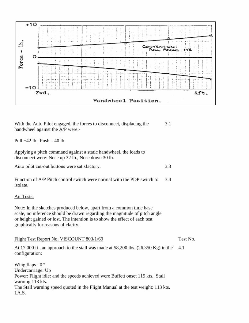
With the Auto Pilot engaged, the forces to disconnect, displacing the
handwheel against the A/P were:-
Pull +42 lb., Push – 40 lb.
Applying a pitch command against a static handwheel, the loads to
disconnect were: Nose up 32 lb., Nose down 30 lb.
3.1
Auto pilot cut-out buttons were satisfactory. 3.3
Function of A/P Pitch control switch were normal with the PDP switch to
isolate.
Air Tests:
Note: In the sketches produced below, apart from a common time base
scale, no inference should be drawn regarding the magnitude of pitch angle
or height gained or lost. The intention is to show the effect of each test
graphically for reasons of clarity.
3.4
Flight Test Report No. VISCOUNT 803/1/69 Test No.
At 17,000 ft., an approach to the stall was made at 58,200 lbs. (26,350 Kg) in the
configuration:
Wing flaps : 0 º
Undercarriage: Up
Power: Flight idle: and the speeds achieved were Buffett onset 115 kts., Stall
warning 113 kts.
The Stall warning speed quoted in the Flight Manual at the test weight: 113 kts.
I.A.S.
4.1

Test condition: At 17,000 ft., with the aircraft trimmed straight and level at 170
kts. I.A.S.. Power for level flight, with the A/P/ and height lock engaged, select
the PDP switch to isolate.
Result (1) The aircraft firmly pitched nose up with a maximum ‘g’ of 1.28 and
entered a climb of 1600 ft/min. maximum, followed by a nose down pitch of 0.55
total ‘g’, then an auto disconnect. The duration from PDP ‘ISOL’ selection to
disconnect was 15 secs.
Result (2) For 9 ½ secs. the aircraft showed no reaction, then, after a mild nose
down pitch of 0.85 g, a firm nose up pitch of 1.3 g followed by an auto
disconnect.
The duration of the test was 20 secs.
Throughout each test, the altitude variation was 400 ft., and the speed variation
within 7 kts. Power setting was 13400 r.p.m. 170 psi torque, which was not
adjusted during the test.
Recognition of the onset of each runaway was immediately apparent and, in
each case, there was no doubt that a manual disconnect would have been made
immediately. Recovery from any attitude caused by the pitch oscillation,
following a manual disconnect, could have been effected smoothly and without
undue difficulty.
Flight Test Report No. VISCOUNT 803/1/69 Test No.
As it proved unnecessary to induce an upset, these tests were omitted. 4.2.3
4.3.1
Test Conditions: At 17,000 ft., trim the aircraft in straight and level flight at 170
kts. I.A.S. with appropriate engine power, A/P and height lock engaged. Isolate
the PDP and, after permitting a phugoid, reinstate the PDP at the top of the
sinusoidal curve and permit the aircraft to rejoin the height lock datum.
Result (1) After the PDP ‘ISOL’ selection, the aircraft maintained the cruise
4.4.1/2

condition for 10 seconds, then entered a nose down pitch with a minimum ‘g’ of
0.7 total and with a maximum rate of decent of -1300 ft/min.
This was followed by a strong nose up pitch of 1.4 g at which point the A/P auto
disconnected. The duration of the test was 24 seconds.
Result (2) At the time of the PDP selection to ‘ISOL’ , a negative stick force of
approximately 5 lb., was being applied. A gentle nose up pitch of 1.05 g with an
altitude gain of 600 ft., a nose down pitch of 0.7 g followed by a stronger N.U.
pitch of 1.25 g. During the resulting climb, the PDP was returned to ‘NORMAL’
and this caused a N.D. pitch of 0.68 ‘g’ as the aircraft returned to the height lock
datum. The duration to selecting the PDP to ‘NORM’ was 36 secs.
4.5.1/2
Result (3) The aircraft maintained the cruise condition for 9 seconds after the
PDP was isolated, then pitched nose up with a max. ‘g’ of 1.25 and auto
disconnected after climbing 700 ft. The duration to disconnect was 18 secs.
4.4.1/2
Flight Test Report No. VISCOUNT 803/1/69 Test No.
As established during the earlier tests, recognition of a fault became very soon
apparent and a manual disconnect would be made. Recovery from any attitude
created by the oscillations experienced would present no difficulty, after a manual
A/P disconnect.
Test Condition: From 17000 ft. straight and level, height lock disengaged and
PDP isolated, using the A/P pitch switch and adjusting the engine power as
required, enter a
climb condition of (a) 500 ft./min. 4.6.1/2
(b) 1000 ft./min. When established, re-instate the PDP. 4.7.1/2
Result (1) Immediately on selection of the PDP to ‘NORM’, at 15,500 ft., and at a
climb rate of +500 ft./min., the aircraft pitched firmly nose up with a max. ‘g’ of
1.18 and the rate of climb increased to + 1000 ft./min. Power was not altered and
the speed continued to reduce. At 30 seconds the speed was 138 kts., the
minimum 128 kts. At 60 secs., after which the aircraft started a very shallow
descent then levelled, accelerating slowly. At 90 secs. The speed was 135 kts. at
17,240 ft. and at 120 secs., 140 kts. at 17,300 ft.
Result (2) From an established rate of climb of 1000 ft./min. the re-instatement of
the PDP caused a very mild nose up pitch of 1.05 g total and a consequent
deceleration. From a start altitude of 17,200 ft., the speed dropped through 134
kits., 17,720 ft. at 30 seconds to a minimum of 129 kts., 17,950 ft. at 45 seconds,
before commencing a slow acceleration, initially with a descent rate of –100
ft./min. to level flight. Speed and heights recorded were at 96 secs. 139 kts, 17,730
ft. and at 120 secs., 142 kts., 17,750 ft.
Flight Test Report No. VISCOUNT 803/1/69 Test No.
These tests indicated that they would certainly be much more difficult to identify,
particularly if the pilot’s attention was distracted. The oscillation, however, if left
unattended, was shown to be very mild and stable, with a minimum speed of 1.29
Vsi before a slow acceleration was commenced.
Test Condition: With the PDP isolated, climb at 160 kts with appropriate engine
power and at 17,000 ft., enter a level cruise condition using the A/P pitch
controller. Simultaneously with the height lock engagement, re-instate the PDP.
Result (1) An immediate very slight nose up pitch before returning to height lock
datum.
Result (2) Aircraft remained on height lock datum with no discernable pitch
changes.
These tests showed that, on the height lock mode selection, sufficient authority
was available to permit the auto pilot to function normally.

Pilot’s Comments – General.
Referring to Page 3, tests 4.2.1/2, as has already been stated, these were easily
identified mainly by the ‘g’ experience, and both Pilots agreed that should this
have occurred in airline flight, the auto pilot would have immediately been
disconnected, and the runaway not allowed to continue, though should it have
been allowed to do so, as can be seen from the results it in no way endangers the
aircraft.
Moreover, on at least two occasions when the test switch was inadvertently
pressed, it brought an immediate reaction from both pilots.
With regards the runaways 4.6.1/2 and 4.7.1/2, on page 5, the lack of ‘g’ as an
"attention getter", meant that this type of runaway might be allowed to continue
to its entirety. However, as can be seen from the results and comments, it once
again did not place the aircraft in an embarrassing situation, and if allowed to run
itself out would then only be recognised by the change in altitude or speed.

Flight Test Department,
British Aircraft Corporation
(Weybridge Division),
Bournemouth (Hurn) Airport.
14th
May, 1969.
Flight Test Report No. VISCOUNT 803/1/69
Viscount – Auto Pilot Investigation.
Summary
Flight Tests, to Schedule No. VISC/251/803 were carried out on an Air Lingus Irish Viscount Type 803,
registration EI-AOJ, to establish if any connection exists between the failure of the Auto Pilot Pitch Datum
Potentiometer (PDP) and the accident to Viscount EI-AOM on the 28th
March 1968.
The results obtained indicate that, under all the conditions of test, a failure or re-engagement of the PDP
does not cause:-
a. Any condition of hazard to the aircraft,
b. that the total ‘g’ did not exceed 0.55 to 1.4, and
c. that during the stick free pitch oscillation, the minimum flight speed encountered did not fall below
1.29 VSI.
The test flight was made from Dublin Airport on the 12th
May, 1969, the crew were as follows:-
Mr. E.D. Glaser, BAC. Pilot
Capt. A.O’Donohue, Aer Lingus, Captain
Mr. R.W. O’Sullivan, Dept. of Transport and Power
Capt. M. Carr, Dept. of Transport and Power
Mr. P. Corbett, Aer Lingus
Mr. R.W.G. Blair, Smiths Industries Ltd.
Mr. R. Cornock, Smiths Industries Ltd.
Mr. J.E. Gray, BAC.
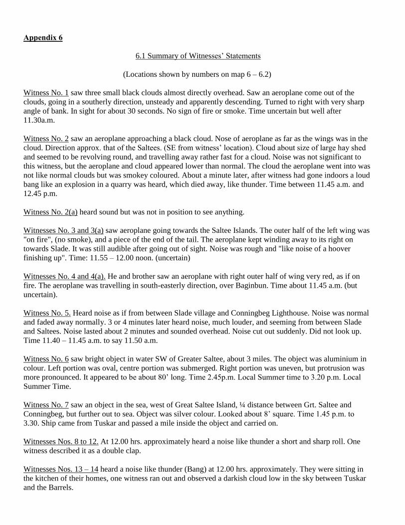
Appendix 6
6.1 Summary of Witnesses’ Statements
(Locations shown by numbers on map 6 – 6.2)
Witness No. 1 saw three small black clouds almost directly overhead. Saw an aeroplane come out of the
clouds, going in a southerly direction, unsteady and apparently descending. Turned to right with very sharp
angle of bank. In sight for about 30 seconds. No sign of fire or smoke. Time uncertain but well after
11.30a.m.
Witness No. 2 saw an aeroplane approaching a black cloud. Nose of aeroplane as far as the wings was in the
cloud. Direction approx. that of the Saltees. (SE from witness’ location). Cloud about size of large hay shed
and seemed to be revolving round, and travelling away rather fast for a cloud. Noise was not significant to
this witness, but the aeroplane and cloud appeared lower than normal. The cloud the aeroplane went into was
not like normal clouds but was smokey coloured. About a minute later, after witness had gone indoors a loud
bang like an explosion in a quarry was heard, which died away, like thunder. Time between 11.45 a.m. and
12.45 p.m.
Witness No. 2(a) heard sound but was not in position to see anything.
Witnesses No. 3 and 3(a) saw aeroplane going towards the Saltee Islands. The outer half of the left wing was
"on fire", (no smoke), and a piece of the end of the tail. The aeroplane kept winding away to its right on
towards Slade. It was still audible after going out of sight. Noise was rough and "like noise of a hoover
finishing up". Time: 11.55 – 12.00 noon. (uncertain)
Witnesses No. 4 and 4(a). He and brother saw an aeroplane with right outer half of wing very red, as if on
fire. The aeroplane was travelling in south-easterly direction, over Baginbun. Time about 11.45 a.m. (but
uncertain).
Witness No. 5. Heard noise as if from between Slade village and Conningbeg Lighthouse. Noise was normal
and faded away normally. 3 or 4 minutes later heard noise, much louder, and seeming from between Slade
and Saltees. Noise lasted about 2 minutes and sounded overhead. Noise cut out suddenly. Did not look up.
Time 11.40 – 11.45 a.m. to say 11.50 a.m.
Witness No. 6 saw bright object in water SW of Greater Saltee, about 3 miles. The object was aluminium in
colour. Left portion was oval, centre portion was submerged. Right portion was uneven, but protrusion was
more pronounced. It appeared to be about 80’ long. Time 2.45p.m. Local Summer time to 3.20 p.m. Local
Summer Time.
Witness No. 7 saw an object in the sea, west of Great Saltee Island, ¼ distance between Grt. Saltee and
Conningbeg, but further out to sea. Object was silver colour. Looked about 8’ square. Time 1.45 p.m. to
3.30. Ship came from Tuskar and passed a mile inside the object and carried on.
Witnesses Nos. 8 to 12. At 12.00 hrs. approximately heard a noise like thunder a short and sharp roll. One
witness described it as a double clap.
Witnesses Nos. 13 – 14 heard a noise like thunder (Bang) at 12.00 hrs. approximately. They were sitting in
the kitchen of their homes, one witness ran out and observed a darkish cloud low in the sky between Tuskar
and the Barrels.

Witness No. 15. This witness was feeding cattle near the Rosslare Golf Pavilion. At 12.00 hrs. he heard a
noise which he described as a loud "whoosh" from Tuskar direction.
Witness No. 16 was walking on strand at 12.00 hrs. approximately he heard a noise which he described "like
a jet coming out of the clouds". A portion of Viscount elevator spring tab was found washed up on the beach
in this location in October, 1968.
Witnesses Nos. 17 and 18. No. 17 at Bing, near Greenore Point. Saw a column of water on left side (north)
of Tuskar "near where the Irish Lights vessel anchors when servicing Tuskar". Column went up as high as
Tuskar Rock itself. Saw two ships "going round the back of the Tuskar afterwards", neither deviated from its
track. Heard a loud noise like water running off rocks. No. 18 heard the noise, but was not in a position to
see anything.
Witness No. 19. Spanish sailor on M.V. Metric thought he saw an aeroplane "at altitude of 3 metres", falling
on left wing. Saw some water thrown into the air, 2-3 miles from ship and in line with Tuskar (Tuskar abeam
about noon).
(At 12.10 Metric was on a course 108° Tuskar 7 miles)
Witness No. 20 on a line between the Black Rock and Carnsore Point, and about nine (9) miles out, saw a
"Mushroom of water". Time: mid-day approx.
Witness No. 21 saw a very large wave on a line over Black Rock in the direction of the Saltees. The time
was 12.00 hrs. approximately.
Witness Nos. 22 – 26 heard noise at 12.00 hrs. approximately, described as like a sharp roll of thunder.
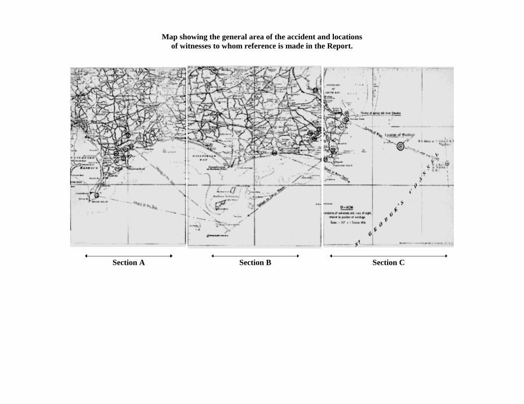
Map showing the general area of the accident and locations
of witnesses to whom reference is made in the Report.
Section A
Section B
Section C

Section A of Main Map

Section B of Main Map
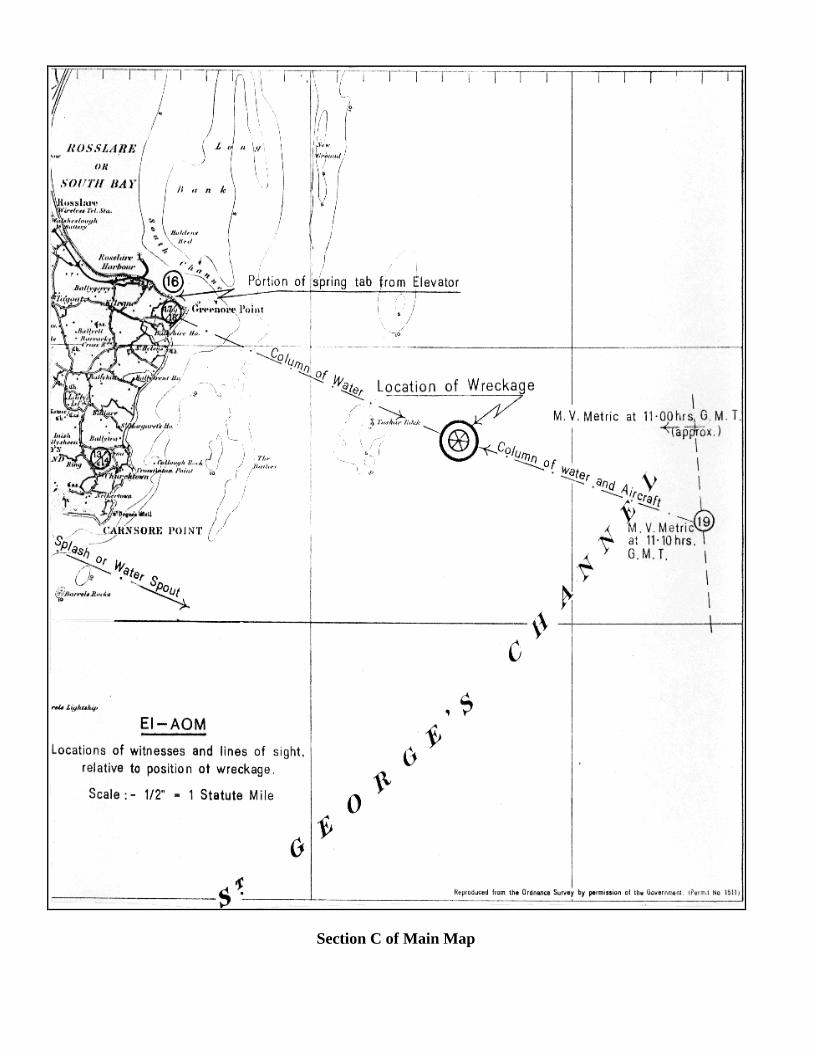
Section C of Main Map

Appendices Photos
1. Photo1
2. Photo2
3. Photo3
4. Photo4
5. Photo5
6. Photo6

Appendices Photo 1

Appendices Photo 2
Appendices Photo 3

Appendices Photo 4
Appendices Photo 5
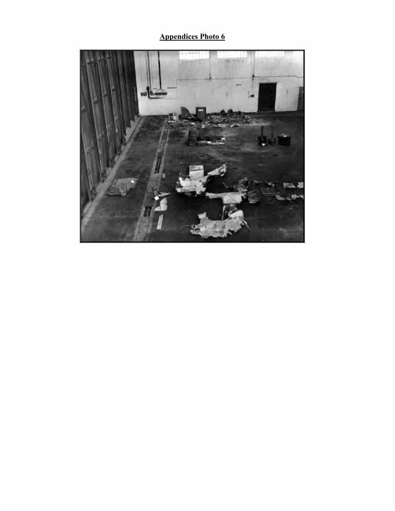
Appendices Photo 6