The Open Construction and Building Technology Journal… · 2016-11-22 · The Open Construction...
10
Send Orders for Reprints to [email protected] The Open Construction and Building Technology Journal, 2014, 8, (Suppl 1: M8) 279-288 279 1874-8368/14 2014 Bentham Open Open Access Experimental Tests on Steel Buckling Inhibited Shear Panels Gianfranco De Matteis * , Federica D’Agostino and Giuseppe Brando Department of Engineering and Geology, INGEO. University “G.d’Annunzio” of Chieti-Pescara, Viale Pindaro, 65127 Pescara, Italy Abstract: Passive protection systems based on the use of metal shear panels represent an effective way for achieving a significant improvement of the seismic response of buildings. Nevertheless, the dissipative capacity of these devices could be limited by buckling phenomena. In order to reduce the influence of instability, "Buckling Inhibited Shear Panels" have been recently introduced as an innovative and convenient solution. It is based on the use of steel plated elements able to restrain out-of-plane displacements of the basic shear plate but without any type of interactions in terms of membrane strains. In this paper the outcomes of an extensive experimental campaign on the proposed system are shown. The tested coupons are made of steel and are characterized by two different thicknesses. Moreover, two technologies for the inhibi- tion of buckling phenomena are examined. The former is able to contain the out-of-plane displacements for the only plate portions that are most involved in the development of the first critical modes. The latter, with a more complex assemblage of the parts, is obtained by inhibiting the out-of-plane deformations of the whole system. The results obtained, compared to the ones given by only steel plates without buckling restraining devices, allow to highlight the increase in terms of en- ergy dissipation capacity that is possible to achieve through the proposed technologies, also evidencing some critical is- sues that can arise when little accuracy in the assembly of the system is spent. Keywords: Buckling inhibited shear panels, dissipative device, experimental analysis, metallic dampers, seismic protection, shear panels, shear walls. 1. INTRODUCTION Metal shear panels constitute a suitable high-performance technology for the seismic protection of both steel and rein- forced concrete buildings. Since the beginning of the 70s such systems have been widely investigated with the purpose of defining the main structural features and behavioural as- pects. This has allowed to reach an adequate knowledge, with particular regard to the stiffening capacity that they are able to offer, as well as to the significant ductility and dissi- pation capacity induced to the frames in which they are ap- plied [1]. Guidelines for their design are currently given in the most advanced codes of North America [2-4] and Asia [5-7], allowing a large worldwide employment for the erec- tion of a significant number of buildings. One of the main issues related to the use of metal shear panels for moment resisting frames, in particular when they are characterized by a limited thickness, concerns the devel- opment of buckling phenomena. In fact, in such cases a det- riment of the inelastic response, under alternating forces, is caused by pinching effects on the hysteretic cycles. This en- tails a reduction of the energy dissipation capacity of the entire system and consequently a larger engagement of the main structural members, such as beams, columns and con- nections. In order to minimize the potentiality of the above degrad- ing phenomena, as an alternative to the adoption of *Address correspondence to this author at the Department of Engineering and Geology, INGEO. University “G.d’Annunzio” of Chieti-Pescara, Viale Pindaro, 65127 Pescara, Italy; Tel: +39 085.4537261; Fax: +39 085 4537255; E-mail: [email protected] significant thicknesses of the base plate, which would lead to solutions that are not economically convenient and usually not complying the capacity design criteria, multi-stiffened thin plates have been proposed in last decades. These are conceived so that transversal and longitudinal stiffeners are properly arranged on the base plate with the task of reducing its free buckling length and, therefore, to postpone in the field of large deformations the occurrence of any instability. Such solutions are often conjugated to the adoption of metallic low yield strength materials, which, apart from al- lowing to have instabilities for very high ductility demands, are characterized by significant deformation capacity [8]. Such an approach allowed to obtain shear panels character- ized by a huge amount of damping capacity [9-13], compa- rable or even superior to the one of the most frequently used dampers, such as BRB (Buckling Restrained Braces) [14], friction and viscous devices. Alternatively to the use of stiffeners, an innovative sys- tem has been recently proposed by the authors, indicated as "Buckling Inhibited Panel" (BIP), in which the mitigation of buckling phenomena is get through the use of steel elements which are arranged parallel to the base plate but are discon- nected from the latter in order to restrain only the out-of- plane deformations of those parts of the panel that may be involved in buckling. The results of the first pilot tests, car- ried out by the authors on aluminium shear plates [15], have shown that, when compared with the more traditional stiff- ened plates, this solution leads to optimal dissipative capaci- ties, characterized by large and full hysteretic cycles. Moreover, it has been observed that the proposed innovative solution ensures a better behaviour in terms of initial stiff-
Transcript of The Open Construction and Building Technology Journal… · 2016-11-22 · The Open Construction...
Send Orders for Reprints to [email protected]
The Open Construction and Building Technology Journal, 2014, 8, (Suppl 1: M8) 279-288 279
1874-8368/14 2014 Bentham Open
Open Access
Experimental Tests on Steel Buckling Inhibited Shear Panels
Gianfranco De Matteis*, Federica D’Agostino and Giuseppe Brando
Department of Engineering and Geology, INGEO. University “G.d’Annunzio” of Chieti-Pescara, Viale Pindaro, 65127
Pescara, Italy
Abstract: Passive protection systems based on the use of metal shear panels represent an effective way for achieving a
significant improvement of the seismic response of buildings. Nevertheless, the dissipative capacity of these devices could
be limited by buckling phenomena. In order to reduce the influence of instability, "Buckling Inhibited Shear Panels" have
been recently introduced as an innovative and convenient solution. It is based on the use of steel plated elements able to
restrain out-of-plane displacements of the basic shear plate but without any type of interactions in terms of membrane
strains. In this paper the outcomes of an extensive experimental campaign on the proposed system are shown. The tested
coupons are made of steel and are characterized by two different thicknesses. Moreover, two technologies for the inhibi-
tion of buckling phenomena are examined. The former is able to contain the out-of-plane displacements for the only plate
portions that are most involved in the development of the first critical modes. The latter, with a more complex assemblage
of the parts, is obtained by inhibiting the out-of-plane deformations of the whole system. The results obtained, compared
to the ones given by only steel plates without buckling restraining devices, allow to highlight the increase in terms of en-
ergy dissipation capacity that is possible to achieve through the proposed technologies, also evidencing some critical is-
sues that can arise when little accuracy in the assembly of the system is spent.
Keywords: Buckling inhibited shear panels, dissipative device, experimental analysis, metallic dampers, seismic protection, shear panels, shear walls.
1. INTRODUCTION
Metal shear panels constitute a suitable high-performance technology for the seismic protection of both steel and rein-forced concrete buildings. Since the beginning of the 70s such systems have been widely investigated with the purpose of defining the main structural features and behavioural as-pects. This has allowed to reach an adequate knowledge, with particular regard to the stiffening capacity that they are able to offer, as well as to the significant ductility and dissi-pation capacity induced to the frames in which they are ap-plied [1]. Guidelines for their design are currently given in the most advanced codes of North America [2-4] and Asia [5-7], allowing a large worldwide employment for the erec-tion of a significant number of buildings.
One of the main issues related to the use of metal shear panels for moment resisting frames, in particular when they are characterized by a limited thickness, concerns the devel-opment of buckling phenomena. In fact, in such cases a det-riment of the inelastic response, under alternating forces, is caused by pinching effects on the hysteretic cycles. This en-tails a reduction of the energy dissipation capacity of the entire system and consequently a larger engagement of the main structural members, such as beams, columns and con-nections.
In order to minimize the potentiality of the above degrad-ing phenomena, as an alternative to the adoption of
*Address correspondence to this author at the Department of Engineering
and Geology, INGEO. University “G.d’Annunzio” of Chieti-Pescara, Viale
Pindaro, 65127 Pescara, Italy; Tel: +39 085.4537261;
Fax: +39 085 4537255; E-mail: [email protected]
significant thicknesses of the base plate, which would lead to solutions that are not economically convenient and usually not complying the capacity design criteria, multi-stiffened thin plates have been proposed in last decades. These are conceived so that transversal and longitudinal stiffeners are properly arranged on the base plate with the task of reducing its free buckling length and, therefore, to postpone in the field of large deformations the occurrence of any instability.
Such solutions are often conjugated to the adoption of metallic low yield strength materials, which, apart from al-lowing to have instabilities for very high ductility demands, are characterized by significant deformation capacity [8]. Such an approach allowed to obtain shear panels character-ized by a huge amount of damping capacity [9-13], compa-rable or even superior to the one of the most frequently used dampers, such as BRB (Buckling Restrained Braces) [14], friction and viscous devices.
Alternatively to the use of stiffeners, an innovative sys-tem has been recently proposed by the authors, indicated as "Buckling Inhibited Panel" (BIP), in which the mitigation of buckling phenomena is get through the use of steel elements which are arranged parallel to the base plate but are discon-nected from the latter in order to restrain only the out-of- plane deformations of those parts of the panel that may be involved in buckling. The results of the first pilot tests, car-ried out by the authors on aluminium shear plates [15], have shown that, when compared with the more traditional stiff-ened plates, this solution leads to optimal dissipative capaci-ties, characterized by large and full hysteretic cycles. Moreover, it has been observed that the proposed innovative solution ensures a better behaviour in terms of initial stiff-

280 The Open Construction and Building Technology Journal, 2014, Volume 8 De Matteis et al.
ness, which, for panels with welded stiffeners, is negatively influenced by the imperfections due to the development of shrinkage effects.
With the purpose of deepening the knowledge on the BIP system, the present paper provides the main outcomes of an experimental campaign recently carried out on thin steel shear panels characterized by different thicknesses and dif-ferent buckling inhibition technologies. Particular attention is devoted to those detrimental effects that could jeopardize the system response when the plates are so thin that the gap between the inhibiter and the inhibited parts become really influencing. In fact, these negative phenomena were not re-corded during the pilot tests, due to the fact that a particular care was spent for their minimization during the assemblage of the experimental specimens.
2. THE EXPERIMENTAL TESTS
Steel shear panels made of S275 steel and characterized by a square shape of 500x500 mm have been placed inside a steel articulated frame with pinned-end beams obtained by coupling two UPN 140 section profiles. Two thicknesses of 0.8mm and 2.5mm have been considered for the base plate.
Friction bolted connections have been designed for joint-ing the metallic plate to the frame, in order to avoid undesir-able premature failure phenomena (bearing stress of the sheet or shear failure of the bolts) capable of compromising the cyclic response of the whole panel.
In order to prevent shear buckling of the base plate by re-straining out-of-plane displacements, two different solutions have been proposed. The first solution represents a ‘‘par-tially’’ BIP (p-BIP), conceived in order to restrain the first four critical modes of the base plate. It has been obtained (see Fig. 1a) by arranging two cross shaped steel elements, having a thickness of 10 mm and a width of 140 mm, at both sides along the diagonals of the plate. These elements have
been characterized by fork-shaped slotted end connections centred on the hinge of the external articulated frame in or-der to do not develop membrane forces when loading the main system. Moreover, in order to reduce the friction be-tween the base plate and the cross shaped elements, a sheet of lexan has been glued to their internal sides. It is to be pointed out that the partial buckling inhibition devices allow some secondary buckling phenomena developing along the medians of the triangular not restrained portions of the base plate.
The second solution produces a ‘‘totally’’ buckling inhib-ited panel (t-BIP). In fact it has been conceived in order to restrain possible out-of-plane displacements of the entire base plate. The external devices, constituting the restraining system, are two octagonal shaped steel plates, which are characterized by a thickness of 10 mm and are able to cover almost the entire base sheeting (Fig. 1b).
Also in this case, lexan has been employed in order to re-duce the friction between the parts. In addition slotted end connections have been used to accommodate in-plane movements of the buckling inhibiting plates.
Totally, the following six full-scale specimens have been considered:
- StSP8: 0.8 mm thick steel shear panel;
- p-BIP St8: 0.8 mm thick steel partially Buckling In-hibited Panel;
- t-BIP St8: 0.8 mm thick steel totally Buckling Inhib-ited shear Panel;
- StSP25: 2.5 mm thick steel shear panel;
- p-BIP St25: 2.5 mm thick steel partially Buckling In-hibited Panel;
- t-BIP St25: 2.5 mm thick steel totally Buckling Inhib-ited shear Panel.
Fig. (1). Tested devices: (a) Partially Buckling Inhibited Panel (p-BIP) and (b) totally Buckling Inhibited Panel (t-BIP).

Experimental Tests on Steel Buckling Inhibited Shear Panels The Open Construction and Building Technology Journal, 2014, Volume 8 281
It is to be highlighted that the used testing apparatus has been initially designed for a 5 mm thick pure aluminum shear panel which, as referred before, have been used in or-der to carry out pilot tests. The smaller thickness of the tested steel plates led to have a larger gap (about 4.0 mm for the thinner coupons and 2.5mm for the others) between the inhibition and the base plate. On the other hand, it must be underlined that the restraining plates have been designed in order to contrast the out of plane deformation of the alumin-ium plates without excessive deformation. Also from this point of view, the fact of having adapted this system for specimens made of another material has led to some counter-indications.
All the tested panels have been diagonally loaded through a MTS810 machine, following the cyclic quasi-static protocol provided by ECCS-CECM [16]. This takes into account a procedure based on some cycles in the elastic range and then on three repetitions for progressively increas-ing displacement amplitudes, defined as integer multiples of the displacement corresponding to the material yielding.
The applied force has been measured by the loading cell of the tested machine, whereas the diagonal displacement of tested panels has been measured by a mechanical diagonal transducer. In addition, four mechanical transducers have been placed on the perimeter of the panel, measuring the possible relative movements between the panel edges and the elements of the perimeter frame.
3. THE EXPERIMENTAL RESULTS
3.1. Thinner Shear Panels (0.8 mm)
The hysteretic responses of the tested specimens “StSP08”, “p-BIP St08” and “t-BIP St08” are shown in (Fig. 2) in terms of shear stress-shear strain relationships.
It can be noticed that the not inhibited shear panel “StSP08” presented relevant pinching effects already for a shear strain of 0,66% (3mm of diagonal displacement). On
the other hand, buckling phenomena have been observed also for protected devices, namely the panels “p-BIP St08” and “t-BIP St08”. In fact, in these cases, the used restraining steel elements have not been completely effective in avoid-ing the development of buckling, due to the relative rele-vance of the gap between the plates and the inhibition de-vices with respect to the small thickness of the firsts.
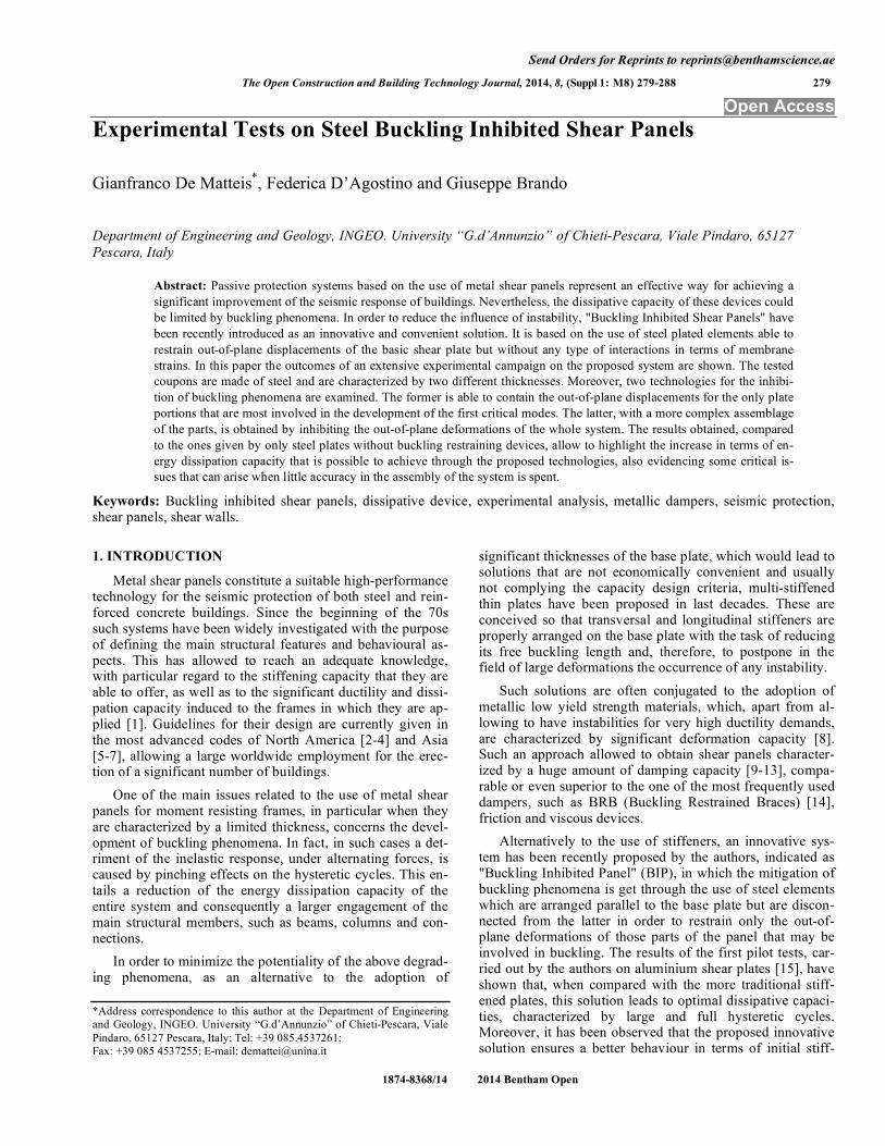
As a consequence, pinching effects have been observed also on the hysteretic cycles of both restrained panels for low shear strain demands. Moreover, it is evident that the dissi-pative response retrieved for these two panels is almost the same (Figs. 3a and 3b). This means that when very thin shear plates are used, their response is fundamentally af-fected from the firsts buckling modes. On the other hand, it has been observed that the inhibition devices were able to contrast the out-of-plane displacements of the buckling waves when these attained a certain amplitude, thus retriev-ing back larger hysteretic cycles with respect to the bare plate “StSP08”. This confirms that the inhibiting action could have a certain level of effectiveness also in presence of the above technological criticalities. This aspect is also evi-dent by analysing the panels response in terms of equivalent viscous damping (Fig. 3c) which, for the buckling inhibited panels, is almost 30% when shear strains higher than 4% are attained, whereas the same parameter is about 20% for the “StSP08” panel.
The analysis of other performance parameters permits to put in evidence that the application of the buckling restrain-ing devices allowed to retrieve higher stiffness (Fig. 3d) and hardening ratio (Fig. 3e), in particular for the “t-BIPSt08” specimen, which, nevertheless, presented a quicker degrada-tion of the normalized strength for a shear strain of 9%, when collapse phenomena propagated significantly in the centre of the plate.
The experimental evidences observed during the tests of 0.8 mm thick plates are synthetically listed in Table 1. A linear elastic behaviour up to a shear strain of ± 0.11% has
Fig. (2). Hysteretic cyclic response of a) “StSP 08”, b) “p-BIPSt08”, c) “t-BIPSt08”.
a) b)
c)
-250
-200
-150
-100
-50
0
50
100
150
200
250
-10% -8% -6% -4% -2% 0% 2% 4% 6% 8% 10%
Shea
r st
ress
(M
Pa)
Shear Strain (%)
-200
-150
-100
-50
0
50
100
150
200
250
-10% -8% -6% -4% -2% 0% 2% 4% 6% 8% 10%
Shea
r str
ess
(MPa
)
Shear Strain (%)
-200
-150
-100
-50
0
50
100
150
200
250
-10% -8% -6% -4% -2% 0% 2% 4% 6% 8% 10%
Shea
r st
ress
(M
Pa)
Shear Strain (%)
282 The Open Construction and Building Technology Journal, 2014, Volume 8 De Matteis et al.
Fig. (3). Comparison between “StSP08”, “p-BIPSt08” e “t-BIPSt08” in terms of: a) dissipated energy by cycle, a) cumulated dissipated en-
ergy, e) equivalent viscous damping, d) secant stiffness, e) hardening ratio.
Table 1. Experimental evidences (0.8mm shear panels).
Shear strain range
(diagonal displacement) St 08 p-BIP St 08 t-BIP St 08
[0, ±0.11%]
([0, ±0.50 mm]) Elastic behaviour
[±0.11%, ±0.66%]
([±0.50 mm, ±3.00 mm])
Buckling phenomena with the
development of pinching effects Inelastic behaviour without buckling phenomena
[±0.66%, ±2.20%]
([±3.00 mm, ±10.00 mm])
Fully development of tension
field mechanisms
Development of buckling waves in
contact with the inhibition system
Plastic deformations of the panel
parts
[±2.20%, ±4.40%]
([±10.00 mm, ±20.00 mm])
Panel Damage closed to the
perimeter members
Panel damage closed to the inhibition
system
Panel Damage at the vertexes of the
plate
[±4.40%, ±9.04%]
([±20.00 mm, ±40.00 mm])
Detachment of the plate from the
connection system up to the
collapse of the specimen
Plate tears closed to the inhibition
system with buckle waves pushing on
the restraining elements
Plate tears in the centre of the panel
with buckle waves strongly pushing
on the restraining elements
Experimental Tests on Steel Buckling Inhibited Shear Panels The Open Construction and Building Technology Journal, 2014, Volume 8 283
been noticed. After this threshold “StSP08” presented the first buckling phenomena with pinching effects on the hys-teretic cycle.
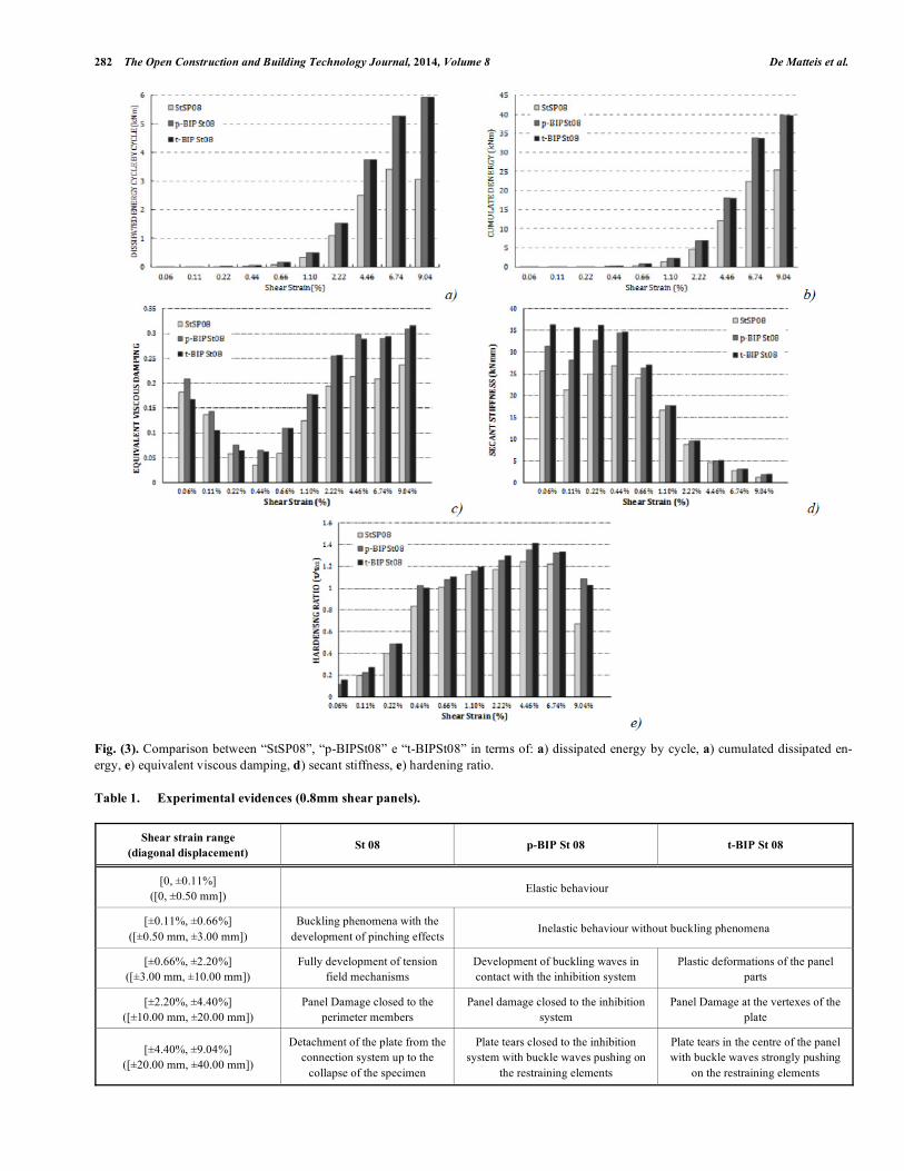
For the same deformation levels, the buckling inhibited panels, “p-BIPSt08” and “t-BIPSt08” provided first inelastic behavior, even if buckling phenomena were not noted up to a shear strain of ± 0.66%. Starting from this demand, also the inhibited panels evidenced some local instabilities, as shown in (Fig. 4), where the state of the tested specimens and the relative hysteretic cycles are represented for a shear strain demand of 1.10%.
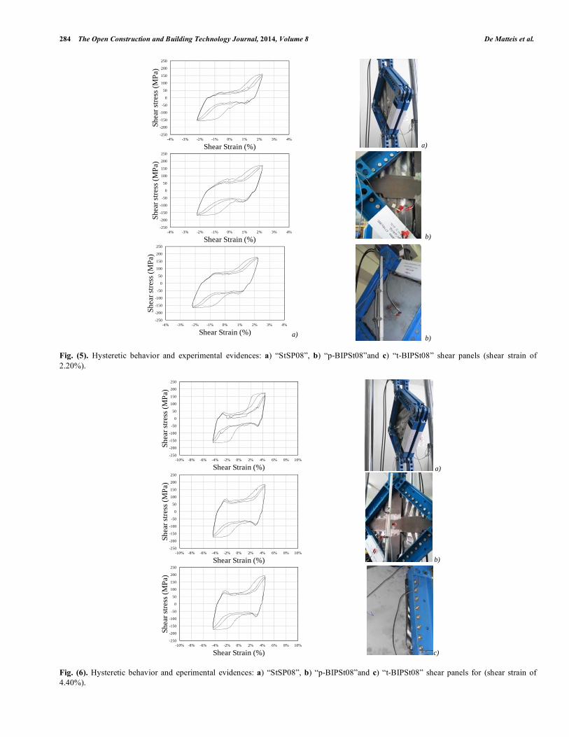
When a shear strain of ±2.20% was reached, the “StSP08” specimen developed the typical behaviour of slen-der panels, characterized by a tension field mechanism (Fig. 5a), while instability patterns of the not inhibited plate portions of “p-BIPSt08” were more evident (Fig. 5b), with buckled waves fully in contact with the restraining devices, whereas, any particular new phenomena have been not regis-tered for the “t-BIPSt08” specimen (Fig. 5c).
For a shear strain of ±4.40%, the first damage on the base plate has been observed. For the not-inhibited steel panel “StSP08”, fractures have been noted closed to the perimeter
members of the frame (Fig. 6a), while, for the “p-BIPSt08” shear panel, same tears concentrated in the proximity of the inhibition systems have been evidenced (Fig. 6b). Finally for the “t-BIPSt08” (Fig. 6c) specimen, ruptures have been ob-served at the vertexes of the plate.
For larger shear demands, the failure of the plate devel-ops more and more, provoking the complete detachment of the shear plate of the “StSP08” from the elements of the pe-rimeter frame, tearing around the diagonals of the “t-BIPSt08” panel, and both such phenomena for the plate of the “p-BIPSt08” specimen. For the latter two panel types, it has been also noted that the plate buckling waves in contact with the external restraining plate provoked out-of-plane deformations of this devices. These deformations, however, resulted to be elastic, as they were recovered after the system disassembling. In Fig. (7), the final states of the tested specimens are shown.
3.2. Thicker Shear Panels (2.5 mm)
In Fig. (8) the hysteretic cycles of the tested 2,5mm tick specimens are illustrated. Also in this case, some buckling phenomena have been noticed even for the buckling
Fig. (4). Hysteretic behavior and experimental evidences: a) “StSP08”, b) “p-BIPSt08” and c) “t-BIPSt08” shear panels (shear strain of
1.10%).
a)
b)
c)
-250
-200
-150
-100
-50
0
50
100
150
200
250
-2.0% -1.5% -1.0% -0.5% 0.0% 0.5% 1.0% 1.5% 2.0%
Shea
r st
ress
(M
Pa)
Shear Strain (%)
-250
-200
-150
-100
-50
0
50
100
150
200
250
-2.0% -1.5% -1.0% -0.5% 0.0% 0.5% 1.0% 1.5% 2.0%
Shea
r st
ress
(M
Pa)
Shear Strain (%)
-250
-200
-150
-100
-50
0
50
100
150
200
250
-2.0% -1.5% -1.0% -0.5% 0.0% 0.5% 1.0% 1.5% 2.0%
Shea
r str
ess
(MPa
)
Shear Strain (%)
284 The Open Construction and Building Technology Journal, 2014, Volume 8 De Matteis et al.
Fig. (5). Hysteretic behavior and experimental evidences: a) “StSP08”, b) “p-BIPSt08”and c) “t-BIPSt08” shear panels (shear strain of
2.20%).
Fig. (6). Hysteretic behavior and eperimental evidences: a) “StSP08”, b) “p-BIPSt08”and c) “t-BIPSt08” shear panels for (shear strain of
4.40%).
a)
b)
a) b)
-250
-200
-150
-100
-50
0
50
100
150
200
250
-4% -3% -2% -1% 0% 1% 2% 3% 4%
Shea
r st
ress
(M
Pa)
Shear Strain (%)
-250
-200
-150
-100
-50
0
50
100
150
200
250
-4% -3% -2% -1% 0% 1% 2% 3% 4%
Shea
r st
ress
(M
Pa)
Shear Strain (%)
-250
-200
-150
-100
-50
0
50
100
150
200
250
-4% -3% -2% -1% 0% 1% 2% 3% 4%
Shea
r st
ress
(M
Pa)
Shear Strain (%)
a)
b)
c)
-250
-200
-150
-100
-50
0
50
100
150
200
250
-10% -8% -6% -4% -2% 0% 2% 4% 6% 8% 10%
Shea
r st
ress
(M
Pa)
Shear Strain (%)
-250
-200
-150
-100
-50
0
50
100
150
200
250
-10% -8% -6% -4% -2% 0% 2% 4% 6% 8% 10%
Shea
r st
ress
(M
Pa)
Shear Strain (%)
-250
-200
-150
-100
-50
0
50
100
150
200
250
-10% -8% -6% -4% -2% 0% 2% 4% 6% 8% 10%
Shea
r st
ress
(M
Pa)
Shear Strain (%)
Experimental Tests on Steel Buckling Inhibited Shear Panels The Open Construction and Building Technology Journal, 2014, Volume 8 285
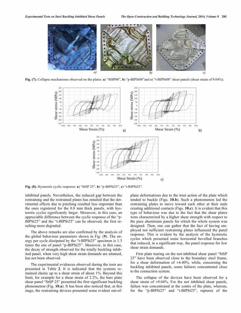
Fig. (7). Collapse mechanisms observed on the plates: a) “StSP08”, b) “p-BIPSt08”and c) “t-BIPSt08” shear panels (shear strain of 9.04%).
Fig. (8). Hysteretic cyclic response: a) “StSP 25”, b) “p-BIPSt25”, c) “t-BIPSt25”.
inhibited panels. Nevertheless, the reduced gap between the restraining and the restrained plates has entailed that the det-rimental effects due to pinching resulted less important than the ones registered for the 0.8 mm thick panels, with hys-teretic cycles significantly larger. Moreover, in this case, an appreciable difference between the cyclic response of the “p-BIPSt25” and the “t-BIPSt25” can be observed, the first re-sulting more degraded.
The above remarks are also confirmed by the analysis of the global behaviour parameters shown in Fig. (9). The en-ergy per cycle dissipated by the “t-BIPSt25” specimen is 1.3 times the one of panel “p-BIPSt25”. Moreover, in this case, the decay of strength observed for the totally buckling inhib-ited panel, when very high shear strain demands are attained, has not been observed.
The experimental evidences observed during the tests are presented in Table 2. It is indicated that the systems re-mained elastic up to a shear strain of about 1%. Beyond this limit, for example for a shear strain of 2.2%, the bare plate shear panel “StSP 25” presented the first significant buckling phenomenon (Fig. 10.a). It has been also noticed that, at this stage, the restraining devices presented some evident out-of-
plane deformations due to the trust action of the plate which tended to buckle (Figs. 10.b). Such a phenomenon led the restraining plates to move toward each other at their ends creating additional contacts (Figs. 10.c). It is evident that this type of behaviour was due to the fact that the shear plates were characterized by a higher shear strength with respect to the pure aluminium panels for which the whole system was designed. Then, one can gather that the fact of having em-ployed not sufficient restraining plates influenced the panel response. This is evident by the analysis of the hysteretic cycles which presented some horizontal bevelled branches that reduced, in a significant way, the panel response for low shear strain demands.
First plate tearing on the not-inhibited shear panel “StSP 25” have been observed close to the boundary steel frame, for a shear deformation of ±4.40%, while, concerning the buckling inhibited panels, some failures concentrated close to the connection system.
The collapse of the devices have been observed for a shear strain of ±9.04%. For the not inhibited shear panels, failure was concentrated at the centre of the plate, whereas, for the “p-BIPSt25” and “t-BIPSt25”, ruptures of the
a) b)
c)
-250
-200
-150
-100
-50
0
50
100
150
200
250
-10% -8% -6% -4% -2% 0% 2% 4% 6% 8% 10%
Shea
r st
ress
(M
Pa)
Shear Strain (%)
-250
-200
-150
-100
-50
0
50
100
150
200
250
-10% -8% -6% -4% -2% 0% 2% 4% 6% 8% 10%
Shea
r st
ress
(M
Pa)
Shear Strain (%)
-250
-200
-150
-100
-50
0
50
100
150
200
250
-10% -8% -6% -4% -2% 0% 2% 4% 6% 8% 10%
Shea
r st
ress
(M
Pa)
Shear Strain (%)

286 The Open Construction and Building Technology Journal, 2014, Volume 8 De Matteis et al.
Fig. (9). Comparison between “StSP25”, “p-BIPSt25” and “t-BIPSt25”: a) dissipated energy by cycle, b) cumulated dissipated energy, c)
equivalent viscous damping, d) secant stiffness, e) hardening ratio.
Table 2. Experimental evidences (2.5 mm shear panels).
Shear strain range
(diagonal displacement) St 25 p-BIP St 25 t-BIP St 25
[0, ±0.11%]
([0, ±0.50 mm]) Elastic behaviour
[±0.11%, ±1.10%]
([±0.50 mm, ±5.00 mm]) First out of plane deformations Elastic behaviour
[±1.10%, ±2.20%]
([±5.00 mm, ±10.00 mm])
First buckling phenomena;
development of pinching effects
Elastic deformation of the
inhibition devices;
Development of slight pinching
phenomena on the hysteretic cycle
Development of slight pinching
phenomena on the hysteretic cycle
[±2.20%, ±4.40%]
([±10.00 mm, ±20.00 mm]) Tension field developing
Panel damage closed to the connection
system
Panel damage closed to the
connection system
[±4.40%, ±6.74%]
([±20.00 mm, ±30.00 mm])
Plate tearing closed to the
perimeter frame and on the
plate diagonal
Panel damage close to the restraining
plate
Panel damage closed to the restrain-
ing plate
[±6.74%, ±9.04%]
([±30.00 mm, ±40.00 mm]) Collapse of the system Collapse of the system Collapse of the system

Experimental Tests on Steel Buckling Inhibited Shear Panels The Open Construction and Building Technology Journal, 2014, Volume 8 287
Fig. (10). Hysteretic behaviour and experimental evidences: a) “StSP25”, b) “p-BIPSt25”and c) “t-BIPSt25” shear panels (shear strain of
2.20%).
Fig. (11). Collapse mechanisms observed on the plates: a) “StSP25”, b) “p-BIPSt25”and “c) t-BIPSt25” shear panels (shear strain of 9.04%).
perimeter connection system occurred (Fig. 11). This last phenomenon was very surprising as the connection system was designed in order to work for friction. The justification was given, according to the fact that the thrust action of the restraining elements on the perimeter members of the frame unloaded the bolted connections which, therefore worked in shear providing not sufficient strength. It is also to be ob-served that at the end of the test the restraining plates pre-sented significant inelastic deformations, thus resulting se-verely damaged, as it is shown in (Fig. 12) for the two re-straining elements of the “t-BIPSt25” specimen, which, evi-dently, lost their straightness (Fig. 12).
CONCLUSION AND VISIONS
The presented experimental tests confirmed that buckling inhibited shear panels proposed by the author in [15] repre-sent an innovative way to obtain effective dissipative devices for the protection of steel and reinforced concrete structures.
Nevertheless, the comparison of tested shear panels made of thin steel plates with the more efficient system made of pure aluminium thicker plate allows to outline some conclu-sive remarks about the counter-indications that can arise when the system is not well conceived, the material features of the base plate are not properly taken into account for the
a)
b)
c)
-250
-200
-150
-100
-50
0
50
100
150
200
250
-4% -3% -2% -1% 0% 1% 2% 3% 4%
Shea
r st
ress
(M
Pa)
Shear Strain (%)
-250
-200
-150
-100
-50
0
50
100
150
200
250
-4% -3% -2% -1% 0% 1% 2% 3% 4%
Shea
r st
ress
(M
Pa)
Shear Strain (%)
-250
-200
-150
-100
-50
0
50
100
150
200
250
-4% -3% -2% -1% 0% 1% 2% 3% 4%
Shea
r st
ress
(M
Pa)
Shear Strain (%)

288 The Open Construction and Building Technology Journal, 2014, Volume 8 De Matteis et al.
design of the system, as well as when proper tolerances are not used.
In particular:
• when buckling inhibited shear panels are designed, it is necessary to manage in a careful way the gaps, which could be particularly significant for very thin sheeting, between the restraining and the restrained parts. In fact, the response of the system for low-medium shear strain demands could be negatively affected by such a gap in terms of dissipative capacity.
• When the gap significantly influence the system re-sponse, the “p-BIP” solution is surely more convenient with respect to the “t-BIP” one. In fact, in this case, the restraining action on the panel portions that are sensitive to the higher critical modes is not necessary, as these do not influence the panel response.
• When larger thicknesses and smaller gaps are applied, the performance of the system could be negatively influ-enced by the out-of-plane deformability of the restraining elements, in particular when they are not properly de-signed according to the strength of the material of the base plate.
All the above conclusions suggest the development of further research activities. In particular, it will be necessary to understand which are the maximum acceptable gaps be-tween the constituting parts and, therefore, to prescribe the tolerances that, depending on the plate thickness, are allowed in the production process. This aspect could be faced by de-veloping appropriate sensitivity analyses by using FEM models calibrated on the basis of available test results. In addition, design provisions, concerning the determination of the correct out-of-plane stiffness that must be assumed for the restraining plates according to the expected shear strength of the base plate, should be provided.
Fig. (12). The inelastic deformations of the restraining plates of
the“p-BIPSt25” specimen.
CONFLICT OF INTEREST
The authors confirm that this article content has no con-flict of interest.
ACKNOWLEDGEMENTS
This study has been developed in the framing of the RE-LUIS 2010–2013 Italian Research Project.
REFERENCES
[1] G. De Matteis, “Effect of lightweight cladding panels on the seis-
mic performance of moment resisting steel frames”, Engineering
Structures, vol. 27, pp. 1662-76, 2005.
[2] ANSI/AISC 341-10, “Seismic provisions for structural steel build-
ings”, Chicago, IL, 2010: American Institute of Steel Construc-
tion.
[3] FEMA 750-P “NEHRP Recommended Seismic Provisions for New
Buildings and Other Structures. 2009 Ed”, Federal Emergency
Management Agency, Washington D.C., 2004
[4] CAN/CSA-S16-01, “Limit states design of steel structures”, To-
ronto (Ontario, Canada), 2009.
[5] GB 50011-2001, Code For Seismic Design Of Buildings, China
Architecture & Building Press, Beijing, 2001, pp. 28-40 (In Chi-
nese).
[6] BSL. Building Standard Law (2000) [In Japanese].
[7] BCJ. Structural provisions for building structures. (1997) Edition-
Tokyo: Building Center Of Japan [In Japanese].
[8] G. De Matteis, G. Brando, and F.M. Mazzolani, “Pure aluminium:
An innovative material for structural applications in seismic engi-
neering”, Construction and Building Materials, vol. 26, pp. 677-86,
2012.
[9] E.S. Mistakidis, G. De Matteis, and A. Formisano, “Low yield
metal shear panels as an alternative for the seismic upgrading of
concrete structures”, Advances in Engineering Software, vol. 38 (8-
9), pp. 626-36, 2007.
[10] K. Tanaka, T. Torii, Y. Saski, T. Miyama, H. Kawai, M. Iwata.
“Practical application of damage tolerant structures with seismic
control panel using low yield point steel to a high-rise steel build-
ing”, Proceedings, Structural Engineering World Wide, Elsevier,
CD-ROM, Paper T190-4, 1998.
[11] G. De Matteis, G. Brando, and F.M. Mazzolani, “Hysteretic behav-
iour of bracing-type pure aluminium shear panels by experimental
tests”, Earthquake Engineering and Structural Dynamics, vol. 40,
no. 10, pp. 1143-1162, 2011.
[12] A. Formisano, F.M. Mazzolani, G. Brando, and De Matteis, G.,
“Numerical evaluation of the hysteretic performance of pure alu-
minium shear panels”. Proceedings of the 5th International Confer-
ence on Behaviour of Steel Structures in Seismic Areas - Stessa
2006, pp. 211-217.
[13] G. De Matteis, F.M. Mazzolani, and S. Panico, “Experimental tests
on pure aluminium shear panels with welded stiffeners”, Engineer-
ing Structures, vol. 30, no. 6, pp. 1734-1744, 2008.
[14] M. Bosco, and E.M. Marino, “Design method and behavior factor
for steel frames with buckling restrained braces”, Earthquake En-
gineering and Structural Dynamics, vol. 42, no. 8, pp. 1243-1263,
2013.
[15] G. Brando, F. D'Agostino, and G. De Matteis, “Experimental tests
of a new hysteretic damper made of buckling inhibited shear pan-
els”, Materials and Structures/Materiaux et Constructions, vol. 46,
no. 12, pp. 2121-2133, 2013.
[16] ECCS-CECM Recommended testing procedure for assessing the
behaviour of structural steel elements under cyclic loads, 1985.
Received: September 15, 2014 Revised: September 27, 2014 Accepted: September 30, 2014
© De Matteis et al.; Licensee Bentham Open.
This is an open access article licensed under the terms of the Creative Commons Attribution Non-Commercial License (http://creativecommons.org/-
licenses/by-nc/3.0/) which permits unrestricted, non-commercial use, distribution and reproduction in any medium, provided the work is properly cited.