The ff of fault current limiter size and type on current ...
14
Turk J Elec Eng & Comp Sci (2017) 25: 1021 – 1034 c ⃝ T ¨ UB ˙ ITAK doi:10.3906/elk-1411-203 Turkish Journal of Electrical Engineering & Computer Sciences http://journals.tubitak.gov.tr/elektrik/ Research Article The effect of fault current limiter size and type on current limitation in the presence of distributed generation Reza MOHAMMADI CHABANLOO 1, * , Ehsan MOKHTARPOUR HABASHI 2 , Meysam FARROKHIFAR 3 1 Department of Electrical Engineering, A.C., Shahid Beheshti University, Tehran, Iran 2 Technical Department, Azarbaijan Shahid Madani University, Tabriz, Iran 3 Polytechnic University of Milan, Milan, Italy Received: 30.11.2014 • Accepted/Published Online: 19.03.2016 • Final Version: 10.04.2017 Abstract: One of the effective mitigation solutions of the problems due to the penetration of distributed generation (DG) into the distribution network is a fault current limiter (FCL). Main attention is given to designs for resistive and inductive FCLs and others should meet the same requirements. At first in this paper network analysis is used to determine a suitable type of limiting impedance of a FCL in a distribution network in the presence of DG and then a comparative study of resistive, inductive, and complex FCLs is conducted to show the effect of size and type of FCL on the amplitude and phase of DG and network fault current. To illustrate the impact of FCLs on relay coordination restoration, an optimization algorithm is used to determine the minimum size of FCL and subsequently the role of FCL impedance type on the coordination time interval of the main and backup relays in a sample IEEE typical distributed network is investigated. Simulations are carried out by programming in MATLAB and the obtained results are reported and discussed. Key words: Fault current limiter, power system protection, distributed generation 1. Introduction Distributed generation (DG) is being applied to the power system and some distribution circuits experiencing significant DG penetration. Distribution systems’ protective devices’ functioning is completely changed with the presence of DG and they cause several problems to the protection of distribution networks. The most commonly mentioned are changes in short circuit levels in different points of the network, exceeding the breaking capacity of circuit breakers, loss of networks’ radial nature, false tripping of feeders, relaying of mal operation, and miscoordination of protection devices[1]. Synchronous-based DG has high fault current contribution as opposed to inverter-based DG and conse- quently has more impact on protective device coordination [2]. To mitigate DG’s impacts on the traditional protection scheme, several methods have been proposed, like limiting DG capacity; modifying the protection system based on using extra circuit breakers, reclosers, and relays; using adaptive protection; and utilizing fault current limiters (FCLs) [3]. One of the effective mitigation solutions of DG’s impacts on the traditional protection scheme is utilizing FCLs in the network [4]. FCLs are known as one of the best countermeasures to solve the problems related to excessive short circuit levels in DG networks and microgrids to ensure suitable coordination of the protective * Correspondence: [email protected] 1021
Transcript of The ff of fault current limiter size and type on current ...

Turk J Elec Eng & Comp Sci
(2017) 25: 1021 – 1034
c⃝ TUBITAK
doi:10.3906/elk-1411-203
Turkish Journal of Electrical Engineering & Computer Sciences
http :// journa l s . tub i tak .gov . t r/e lektr ik/
Research Article
The effect of fault current limiter size and type on current limitation in the
presence of distributed generation
Reza MOHAMMADI CHABANLOO1,∗, Ehsan MOKHTARPOUR HABASHI2,Meysam FARROKHIFAR3
1Department of Electrical Engineering, A.C., Shahid Beheshti University, Tehran, Iran2Technical Department, Azarbaijan Shahid Madani University, Tabriz, Iran
3Polytechnic University of Milan, Milan, Italy
Received: 30.11.2014 • Accepted/Published Online: 19.03.2016 • Final Version: 10.04.2017
Abstract: One of the effective mitigation solutions of the problems due to the penetration of distributed generation
(DG) into the distribution network is a fault current limiter (FCL). Main attention is given to designs for resistive
and inductive FCLs and others should meet the same requirements. At first in this paper network analysis is used to
determine a suitable type of limiting impedance of a FCL in a distribution network in the presence of DG and then a
comparative study of resistive, inductive, and complex FCLs is conducted to show the effect of size and type of FCL
on the amplitude and phase of DG and network fault current. To illustrate the impact of FCLs on relay coordination
restoration, an optimization algorithm is used to determine the minimum size of FCL and subsequently the role of FCL
impedance type on the coordination time interval of the main and backup relays in a sample IEEE typical distributed
network is investigated. Simulations are carried out by programming in MATLAB and the obtained results are reported
and discussed.
Key words: Fault current limiter, power system protection, distributed generation
1. Introduction
Distributed generation (DG) is being applied to the power system and some distribution circuits experiencing
significant DG penetration. Distribution systems’ protective devices’ functioning is completely changed with the
presence of DG and they cause several problems to the protection of distribution networks. The most commonly
mentioned are changes in short circuit levels in different points of the network, exceeding the breaking capacity
of circuit breakers, loss of networks’ radial nature, false tripping of feeders, relaying of mal operation, and
miscoordination of protection devices[1].
Synchronous-based DG has high fault current contribution as opposed to inverter-based DG and conse-
quently has more impact on protective device coordination [2]. To mitigate DG’s impacts on the traditional
protection scheme, several methods have been proposed, like limiting DG capacity; modifying the protection
system based on using extra circuit breakers, reclosers, and relays; using adaptive protection; and utilizing fault
current limiters (FCLs) [3].
One of the effective mitigation solutions of DG’s impacts on the traditional protection scheme is utilizing
FCLs in the network [4]. FCLs are known as one of the best countermeasures to solve the problems related to
excessive short circuit levels in DG networks and microgrids to ensure suitable coordination of the protective
∗Correspondence: [email protected]
1021

MOHAMMADI CHABANLOO et al./Turk J Elec Eng & Comp Sci
devices and subsequently safe operation of the grid [5,6]. The FCL is a low impedance device that has no action
during normal operation. However, during a fault it takes fast action by inserting high impedance in series
with the power delivery system to limit the fault current value to a preset limit [7]. The impact of the FCL
on a distribution network in the presence of DG is investigated and the possible use of FCLs for mitigating
protection system faults due to DG is discussed [8]. The FCL in series with DG and a utility interconnection
point is used to restore fault current levels to original values, and the FCL impedance is determined by particle
swarm optimization [9].
FCLs have emerged as an alternative to limit prospective short-circuit currents to lower levels and improve
power system reliability, stability, and security by reducing the fault currents [10].
How and when FCL impedance enters the network is different regarding the type of FCL. Moreover,
the value of this impedance is variable in some FCLs. For the sake of simplicity, the value of this impedance
is assumed to be constant at the time of fault occurrence [11]. Presently two basic designs are given main
attention: resistive and inductive. Most other proposed devices are based on these designs and must meet the
same requirements [11].
The FCL impedance leads to limitation of fault current and since the cost of the FCL is relative to its
impedance, the optimum size and cost of FCL is preferred to be used [12]. Selection of the FCL impedance type
and its size by genetic algorithm (GA) is presented to restore the effective coordination of overcurrent (OC)
relays [13], and optimal resistance of a superconducting FCL and its protective coordination are determined
when it is connected to a wind-turbine generation system in series [14]. Another method is used to find the
optimized resistance of resistive FCLs based on the GA to handle the requirements of restoration of original
relay settings [15]. Electrical and thermal behaviors of resistive and inductive superconducting FCLs are used
to investigate the effect of superconducting FCL parameter variations on its performance based on multiple
criteria decision-making techniques [16].
Methods for the estimation of the effects of FCLs on the short circuit are essential for power system
development including the FCL. These papers show the effects of type and size of FCLs in limitation but do
not investigate the analytical and systematic effects of FCLs on the network structure. This paper investigates
the required limiting impedance of a FCL installed in a distribution network by using network analysis and
comparative study of resistive FCLs (R-FCLs) and inductive FCLs (X-FCLs) for power systems in the presence
of DG. In network analysis, the limiting impedance was constant. For determining the impedance of FCLs
and investigating the size and type of FCL impedances, the optimization algorithm [13] is used and optimum
sizes of R-, X-, and complex (C-)FCLs are obtained. The effects of the installed FCLs in series with DG on
the coordination restoration of the protection system and the coordination time interval (CTI) between main
and backup relays are investigated and simulations are carried out for R-, X-, and C-FCLs, and the results are
shown and discussed.
2. System study and formulation analysis
R- and X-FCLs were introduced to limit fault currents in the distribution network in many articles. In this
paper, a range of fault current limitation by R-, X-, and C-FCLs in the presence of DG is investigated. A sample
distribution network with DG and FCLs is shown in Figure 1 where ZN−DG is the network equal impedance
up to the installed DG and ZDG−F is equal impedance from the DG to the fault point, so the short circuit
current in the fault point would be achieved by:
1022

MOHAMMADI CHABANLOO et al./Turk J Elec Eng & Comp Sci
Figure 1. DG and FCL connected to the distribution network.
IF = INet + IDG&FCL, (1)
where INet is the network fault current and IDG&FCL is the DG fault current, which is limited by the FCL. It
is obvious that the amplitude of fault current is reduced by increasing FCL impedance, so the resistance and
reactance of the FCL have a great effect on reducing DG fault current. Supposing that Zeq = Req + jXeq is
the impedance of the network from DG to the fault point without FCL and ZFCL = RFCL + jXFCL is FCL
impedance, if the Zeq and ZFCL vectors are in the same direction the maximum DG fault current limitation
would be achieved, which means Req = RFCL and Xeq = XFCL . To reduce the total fault current through the
network, the sum of the DG fault current and network fault current should be minimized.
FCLs, by inserting high impedance into the network, not only decrease the amplitude of the fault current
but also change the angle of DG fault current. Consider Figure 2, which is achieved from short circuit analysis
by Thevenin theory and dividing the circuit in Figure 1 into two parts. The upper circuit shows the network
short circuit without any load and the bottom shows load current in the network. Fault current at any point
of the network is achieved by calculating the sum of currents in these two circuits.
Figure 2. Short circuit network in Thevenin theory.
When DG was installed in the network, the network impedance matrix changed; the DG impedance is
added between the node and ground so one row and one column are added to the network impedance matrix
1023

MOHAMMADI CHABANLOO et al./Turk J Elec Eng & Comp Sci
as shown in Eq. (2). By setting DG voltage to zero, a new impedance matrix would be achieved by omitting
the DG’s row and column (shown in Eq. (3)).
V1
V2
...
Vn
VDG
=
Z11 Z12 ... Z1n Z1k
Z21 Z22 ... Z1n Z2k
... ... ... ...
Zn1 Zn2 ... Znn Znk
Zk1 Zk2 ... Zkn Zkk + ZDG
I1
I2
...
In
IDG
(2)
Zbus,new = Zbus,old − ZcolZ−1commonZrow (3)
Based on Thevenin theory and using the impedance matrix, fault current through the network can be calculated.
The network fault current in the fault point (j) would be:
If =V
(0)j
Vjj,new=
V(0)j
Zjj − ZkjZjk
Zkk+ZDG+ZFCL
, (4)
where V(0)j is the voltage of the fault point before short circuit and Zjj,new is the new network Thevenin
impedance in the fault point. Maximum DG fault current occurred for faults near the DG; hence, to calculate
the maximum DG fault current, Zjj is replaced by Zkkj :
If =V
(0)j (Zkk + ZDG + ZFCL)
Zkk(ZDG + ZFCL)=
V(0)j
Zkk+
V(0)j
ZDG + ZFCL. (5)
This shows that the network fault current in the DG connection point is equal to the sum of DG fault current
and network fault current without DG. Fault current through the network by considering load current can be
written as:
Ikj =Vk−Vj
ZDG−F=
(V(0)k −ZkjIf )−(V
(0)j −ZjjIf )
ZDG−F
=(V
(0)k −V
(0)j )−(Zkj−Zjj)IfZDG−F
=V
(0)j
Zkk+
V(0)j
ZDG+ZFCL+
V(0)k −V
(0)j
ZDG−F
. (6)
The vector diagram of the network current and DG current with and without DG and using R- and X-FCLs is
illustrated in Figure 3. The horizontal axis is chosen as a reference and shows the angle of voltage at the fault
point before the fault occurred. According to this, DG limited fault current by FCL (IFCL&DG), network fault
current without DG branch (INet), and load current (Ikj(0)) are summed and established the total network
fault current near the DG. If the sum of load current and the network fault current (INet) is calculated, it can
be seen that load current is very small against the network fault current and does not affect the network current
angle sensitively, so the equivalent current of the network fault current and load current can be shown as INet
in Figure 3. It is clear that the fault current results from the DG fault current and network fault current.
When there is no FCL in the network, the angles of DG and network fault currents would be close to each
1024

MOHAMMADI CHABANLOO et al./Turk J Elec Eng & Comp Sci
other. Based on Eq. (6) the angle between the DG and network fault currents vectors has an important role
for reducing total fault current through the network. In Figure 3, R- and X-FCLs not only limited DG fault
current amplitude but also increased the phase difference between the DG and network fault currents vectors,
so this causes the sum of vectors to be larger than in the case where there is no FCL in the network. It should
be noted that in Figure 3, the FCL has large impedance.
Figure 3. Vector diagram of DG fault current limitation by FCL.
The distribution network has large resistance and the X/R ratio is low, so the network fault current
(INet) is independent of the network’s other parameters. As shown in Figure 3, network fault current is placed
between DG fault currents in pure resistive and pure inductive modes. The angle of the DG fault current is:
θ = tan−1(XFCL +XDG
RFCL). (7)
At lower impedance of the FCL, if inductance of the FCL increases, the angle of DG fault current approaches
90◦ , and if the resistance of the FCL increases, this angle approaches the network fault current angle and
limitation is reduced in comparison to the X-FCL. With large FCL impedance (more than 7 times the DG
impedance), the angle between DG fault current and the network fault current increases, so more limitation
will be achieved by which R- and X-FCLs can make more phase difference.
In a distribution network that has more reactive fault current due to the inductive upstream network,
the R-FCL has more capability to make a phase difference between vectors, so the R-FCL has more limitation
in comparison with the X-FCL. Consequently, pure R- and X-FCLs not only reduce DG fault current amplitude
but also make a large phase difference, which is very effective in DG fault current limitation. Using the C-FCL
can reduce DG fault current amplitude more than R- and X-FCLs but can make less phase difference between
the DG fault current and the network fault current, so with high FCL impedance the C-FCL has less limitation
in comparison with R- and X-FCLs.
1025

MOHAMMADI CHABANLOO et al./Turk J Elec Eng & Comp Sci
3. Simulation results
The IEEE 30-bus system shown in Figure 4 is used as a case study in this paper to show the effects of type and
size of FCL on the fault current limitation in the presence of DG. The IEEE 30-bus system can be considered
as a meshed subtransmission/distribution network. The network consists of 30 buses (132 and 33 kV buses),
37 lines, 6 generators, 4 transformers, and 86 OC relays here fed from three primary distribution substations
(132/32 kV at buses 1, 6, and 13). The generator, line, and transformer information was given in [17]. It is
assumed that directional OC relays were installed on both sides of a line and OC relays were coordinated before
DG connection. Three synchronous generators are used as DG in buses 3, 10, and 15 and their specifications
are shown in Table 1. These generators are connected to the network via 10 MVA and 0.05 PU reactance
transformers.
Figure 4. IEEE 30-bus distribution network.
Table 1. DG specifications.
MVA Transient reactance Power factor Installing busDG 1 2 0.15 0.9 lag 3DG 2 4 0.10 0.9 lag 10DG 3 7 0.10 0.9 lag 15
1026

MOHAMMADI CHABANLOO et al./Turk J Elec Eng & Comp Sci
For avoiding the large size of FCL impedance and subsequently the high cost of FCL installation, an
acceptable range of FCL limitation should be selected instead of full limitation of fault currents. For determining
the impedance of FCLs and investigating the size and type of FCL impedances, an optimization algorithm [13]
is used. The impedance of FCLs is selected with an optimization algorithm considering that the fault currents
flowing (after installing the DG and FCLs) all over the network are limited to an acceptable range. This range
is determined as a coefficient of fault current before installing the DG and is shown as parameter ka in Eq. (8).
FCL impedance determination and the coordination flowchart are shown in Figure 5. The objective function
(OF) in the optimization algorithm, which should be minimized, is formulated as follows:
Figure 5. FCL impedance determination and coordination program flowchart.
1027

MOHAMMADI CHABANLOO et al./Turk J Elec Eng & Comp Sci
OF = Z1 + Z2 + ...+ Zn
All Ifi(withDG) ≤ ka × Ifi(withoutDG), (8)
where parameters Z1 , Z2 . . . Zn are the impedances of FCLs, and Ifi is the maximum fault current flow
of branch i in the network with/without DG. By analyzing and using the genetic algorithm to overcome the
miscoordination of main and backup relays due to inserting DG into the network and changing the short circuit
(SC) current, and considering the minimum size of FCL impedances, the OF is introduced as below:
OF = α×N∑i=1
(ti)2+ β ×
P∑k=1
(∆tmbk − |∆tmbk|)2, (9)
∆tmbk = tbk − tmk − CTI, (10)
where ∆tmbk is the operating time difference with CTI for the k th relays pairs, ti is the ith relay operating
time for a fault close to the circuit breaker of the ith relay, tmk and tbk are the operating times of the main
and backup relays for a fault close to the circuit breaker of the main relay, and N and P are the number of
relays and primary/backup (P/B) current pairs respectively. Each P/B current pair is represented by k and
varies from 1 to P and each relay is represented by i and varies from 1 to N.
Looped distribution networks are usually protected with directional OC relays, which are installed on
both sides of a line. After installing DG in the network, fault currents levels change at different points of the
network and cause miscoordination between relays. If DG rated power is small, recoordination between relays
can be achieved by resetting the relays; otherwise, the SC level increases more than the limited range and
coordination of relays is lost. One of the effective solutions in restoring the OC relay coordination is using FCLs
in the network. To show the results, the SC calculation is investigated on the IEEE 30-bus system in two cases:
a) without DG connection and b) with DG connection in buses 3, 10, and 15. Table 2 shows the fault current
through the main and backup relays with/without DG (the table is reduced by the authors to some specific
main and backup relays). According to Table 2, fault current passing through the relays changes because of DG
current injection. This change depends on the size and placement of the DG. After DG connection, fault currents
increased and maximum fault current for backup relay belonged to the (9–29) relay pairs, which increased from
834.6 to 1242 A, and maximum fault current for the main relay belonged to the (18–38) relay pairs, which
increased by 41.2%. This increase changes the relay operating time and time interval (TI) between all main
and backup relays. Sometimes this change does not affect the CTI but some relays are miscoordinated because
of fault current changes. In this application the relay CTI is 0.3 and after DG connection the acceptable value
changes to 0.25 to coordinate relays. Table 3 shows some main and backup relay CTIs, where the negative
values show miscoordination because of DG fault current.
Now to limit the fault current amplitude and restore coordination of relays, which is missed by adding
DG, the optimization algorithm is implemented to determine series FCL optimum impedances individually to
reduce the overall costs. By using the R-FCL, FCL impedance in buses 3, 10, and 15 is obtained as 9, 18, and 11
PU, respectively. Subsequently X- and C-FCL impedances are calculated and Table 4 shows comparison results
between them (impedances are calculated in 100 MVA base). The R-FCL with 38.0 PU has better current
limitation than the X-FCL and C-FCL with 51 PU and 52.3 PU impedances, respectively.
1028

MOHAMMADI CHABANLOO et al./Turk J Elec Eng & Comp Sci
Table 2. Main and backup relay fault currents without/with DG.
Main relay Backup Main relay Backup relay Main relay Backup relayno. relay no. fault current fault current fault current fault current
(A) without DG (A) without DG (A) with DG (A) with DG19 15 4996 1169 5363 144538 18 2226 2226 3143 23029 20 6415 950 7141 120010 20 6933 942 7485 11919 21 6414 620 7241 78410 21 6933 616 7485 7789 29 6415 835 7241 1242
Table 3. Coordination time interval between some main and backup relays after DG installation.
Main relay no. Backup relay no. Time interval (s)19 15 0.1339 20 –0.04110 20 –0.0179 21 0.04010 21 0.063
Table 4. The worst time interval and sum of R-, X-, and C-FCL impedances by optimization method.
FCL type Impedances (PU) Worst time Sum of FCLFCL-bus 3 FCL-bus 10 FCL-bus 15 interval (s) impedances
R-FCL 9 18 11 0.25 38X-FCL 19 24 8 0.25 51C-FCL, Z (1+j) 7.8(1+j) 13.4(1+j) 4.9(1+j) 0.25 52.3
Figure 6 shows DG fault current limited by R- and X-FCLs. As it can be seen, by installing DG, the
current through the relay near the DG is increased by 41.2%. To limit DG fault current a FCL is used and
results show that the fault current is limited saliently at lower impedance of the FCL. DG fault current limiting
rate is not changing linearly with FCL impedance; limitation at low impedances of the FCL is increased with a
severe slope and by increasing the FCL impedance is not changed very much. Using a 6.0 PU X-FCL, the fault
current of DG reaches 10%, but by increasing FCL reactance to 25.0 PU the fault current is not limited linearly
and is limited less than before, reaching 4.4%. By using the 6.0 PU FCL, a high percentage of limiting can
be achieved, the cost of the FCL is reduced impressively, and relay miscoordination can be solved by resetting
relays so it is not necessary to use a 25.0 PU bulky and expensive FCL to limit the fault current. As was
explained before, at lower impedance of the FCL, by increasing the inductance of the FCL, the angle of DG
fault current approaches 90◦ and has more limitation effect in comparison with increasing the resistance. As
Figure 6 shows, the X-FCL at low impedances (up to 4 PU) is more effective than the R-FCL, but at higher
impedances due to the difference between the network fault current and DG current phases, the R-FCL has
better results in current limitation.
1029

MOHAMMADI CHABANLOO et al./Turk J Elec Eng & Comp Sci
Figure 6. DG fault current limitation by R-FCL and X-FCL.
As mentioned before, to restore coordination, the optimization algorithm should be used to minimize
TI and OF when the CTI for relays and other protection devices, which is set before entering DG, remains
constant after DG and FCL initiation. Figure 7 shows the TI between the (9–29) relay pair, which is the worst
miscoordination. In this case the X-FCL has more effects with low impedance and the R-FCL has the best role
in the relay coordination restoration. By increasing the FCL impedances the TI approach to the acceptable
range and relay coordination is not missed by the DG fault current.
Figure 7. Time interval between (9–29) relay pairs after installing R-, X-, and C-FCLs.
1030
MOHAMMADI CHABANLOO et al./Turk J Elec Eng & Comp Sci
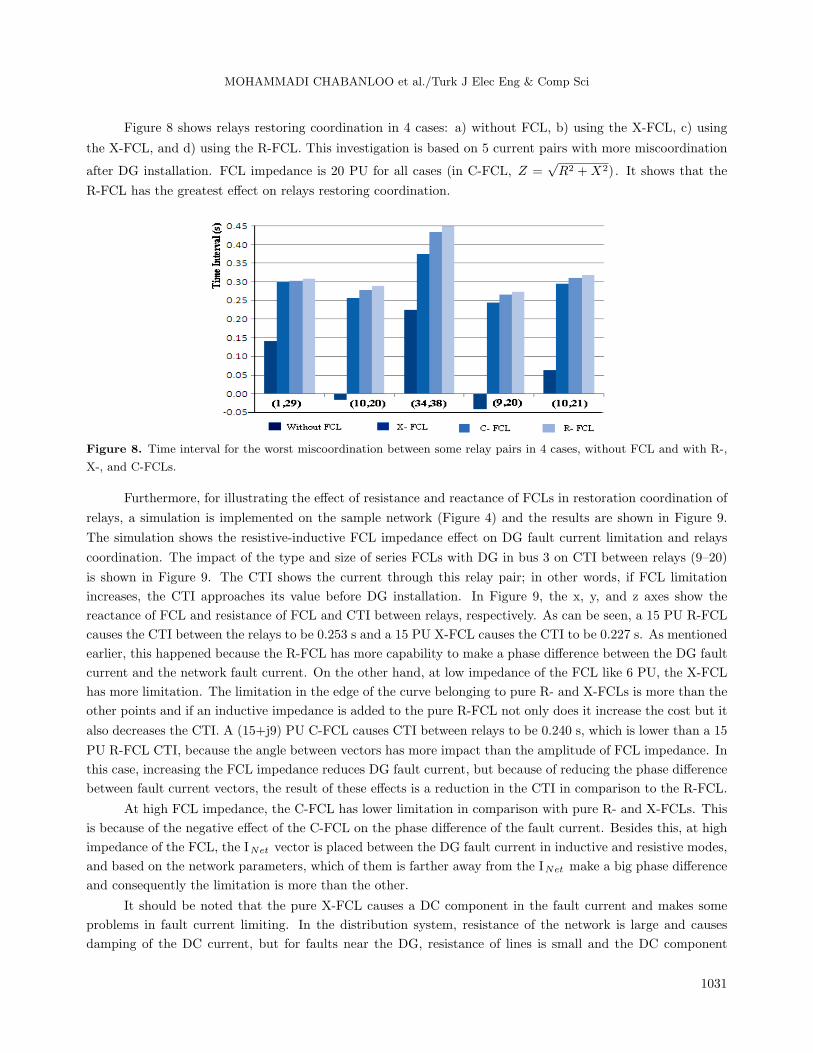
Figure 8 shows relays restoring coordination in 4 cases: a) without FCL, b) using the X-FCL, c) using
the X-FCL, and d) using the R-FCL. This investigation is based on 5 current pairs with more miscoordination
after DG installation. FCL impedance is 20 PU for all cases (in C-FCL, Z =√R2 +X2). It shows that the
R-FCL has the greatest effect on relays restoring coordination.
Figure 8. Time interval for the worst miscoordination between some relay pairs in 4 cases, without FCL and with R-,
X-, and C-FCLs.
Furthermore, for illustrating the effect of resistance and reactance of FCLs in restoration coordination of
relays, a simulation is implemented on the sample network (Figure 4) and the results are shown in Figure 9.
The simulation shows the resistive-inductive FCL impedance effect on DG fault current limitation and relays
coordination. The impact of the type and size of series FCLs with DG in bus 3 on CTI between relays (9–20)
is shown in Figure 9. The CTI shows the current through this relay pair; in other words, if FCL limitation
increases, the CTI approaches its value before DG installation. In Figure 9, the x, y, and z axes show the
reactance of FCL and resistance of FCL and CTI between relays, respectively. As can be seen, a 15 PU R-FCL
causes the CTI between the relays to be 0.253 s and a 15 PU X-FCL causes the CTI to be 0.227 s. As mentioned
earlier, this happened because the R-FCL has more capability to make a phase difference between the DG fault
current and the network fault current. On the other hand, at low impedance of the FCL like 6 PU, the X-FCL
has more limitation. The limitation in the edge of the curve belonging to pure R- and X-FCLs is more than the
other points and if an inductive impedance is added to the pure R-FCL not only does it increase the cost but it
also decreases the CTI. A (15+j9) PU C-FCL causes CTI between relays to be 0.240 s, which is lower than a 15
PU R-FCL CTI, because the angle between vectors has more impact than the amplitude of FCL impedance. In
this case, increasing the FCL impedance reduces DG fault current, but because of reducing the phase difference
between fault current vectors, the result of these effects is a reduction in the CTI in comparison to the R-FCL.
At high FCL impedance, the C-FCL has lower limitation in comparison with pure R- and X-FCLs. This
is because of the negative effect of the C-FCL on the phase difference of the fault current. Besides this, at high
impedance of the FCL, the INet vector is placed between the DG fault current in inductive and resistive modes,
and based on the network parameters, which of them is farther away from the INet make a big phase difference
and consequently the limitation is more than the other.
It should be noted that the pure X-FCL causes a DC component in the fault current and makes some
problems in fault current limiting. In the distribution system, resistance of the network is large and causes
damping of the DC current, but for faults near the DG, resistance of lines is small and the DC component
1031

MOHAMMADI CHABANLOO et al./Turk J Elec Eng & Comp Sci
Figure 9. R-, X-, and C-FCL impacts on coordination time interval.
of the fault current has less damping by X-FCL installation. If the FCL is operated in zero current crossing
time, the DC component of the fault current is not created. In other cases, a solution should be considered
for fault current increased by the DC component in the X-FCL. One solution can be increasing resistance in
FCL impedance (using the C-FCL) for increasing the damping of the DC component. If the X-FCL is used,
the reactance of the FCL should be increased in a specific range to prevent increasing of current peak from
the acceptable range. On the other hand, when the X-FCL is used, it should be ensured that the reactance of
the FCL with the capacitor of the system does not make a resonant circuit. If FCL reactance is large it can
cause resonance and overvoltage in the system. Figure 10 shows a capacitor in connection with the DG bus.
Inductance of the FCL is determined by considering load harmonics and the capacitor of the system to prevent
resonance, so the equivalent inductance to prevent resonance would be:
Figure 10. FCL impedance impact in restoration of relay coordination.
L ≤ 1
C(2πfh)2, (11)
where h is the number of the highest harmonic and f is main system frequency. It is possible to install a
capacitor far from the DG or in the DG branch. In the overall case, harmonic load flow should be implemented
to determine the maximum reactance of the FCL.
1032

MOHAMMADI CHABANLOO et al./Turk J Elec Eng & Comp Sci
4. Conclusion
In this paper, the FCL is used in series with the DG unit to minimize the negative effects of the DG on the
protection system of the distribution network. The effects of size and type of FCL (resistive, inductive, and
complex) in series with DG are investigated in fault current limitation. It is shown that besides the impedance
range of the FCL the angle between the DG current vector and the network current vector has an important
role for reducing total fault current through the network. R- and X-FCLs not only limited DG fault current
amplitude but also increased the phase difference between DG and network fault current vectors. At low
impedance of FCL, the X-FCL has better limitation, and at high impedance of FCL the R-FCL has better
limitation. CTI shows the current through the relay pairs; in other words, if the FCL limitation increases, the
CTI approaches its value before DG installation. The limitation of pure R- and X-FCLs is more than the other
points and if an inductive impedance is added to the pure R-FCL not only does it increase the cost but it also
decreases the CTI. The impact of type and size of series FCL with DG on CTI between relays was investigated
and the results were discussed.
References
[1] Shahriari SAA, Abapour M, Yazdian A, Haghifam M-R. Minimizing the impact of distributed generation on
distribution protection system by solid state fault current limiter. In: IEEE 2010 Transmission and Distribution
Conference and Exposition; 19–22 April 2010; New Orleans, LA, USA. New York, NY, USA: IEEE. pp. 1–7.
[2] Nimpitiwan N, Heydt GT, Ayyanar R, Suryanarayanan S. Fault current contribution from synchronous machine
and inverter based distributed generators. IEEE T Power Deliver 2007; 22: 634-641.
[3] Yazdanpanahi H, Li YW, Xu W. A new control strategy to mitigate the impact of inverter-based DGs on protection
system. IEEE T Smart Grid 2012; 3: 1427-1436.
[4] Chabanloo RM, Abyaneh HA, Agheli A, Rastegar H. Overcurrent relays coordination considering transient be-
haviour of fault current limiter and distributed generation in distribution power network. IET Gener Transm Dis
2011; 5: 903-911.
[5] Ebrahimpour M, Vahidi B, Hosseinian SH. A hybrid superconducting fault current controller for DG networks and
microgrids. IEEE T Appl Supercon 2013; 23: 5604306.
[6] Hadjsaid N, Canard JF, Dumas F. Dispersed generation impact on distribution networks. IEEE Comput Appl Pow
1999; 12: 22-28.
[7] Ghanbari T, Farjah E. Development of an efficient solid-state fault current limiter for microgrid. IEEE T Power
Deliver 2012; 27: 1829-1834.
[8] Morandi A. Fault current limiter: an enabler for increasing safety and power quality of distribution networks. IEEE
T Appl Supercon 2013; 23: 5604608.
[9] Zeineldin HH, Xiao W. Optimal fault current limiter sizing for distribution systems with DG. In: IEEE 2011 Power
and Energy Society General Meeting; 24–29 July 2011; San Diego, CA, USA. New York, NY, USA: IEEE. pp. 1-5.
[10] Hatta H, Muroya S, Nitta T, Shirai Y, Taguchi M. Experimental study on limiting operation of superconducting
fault current limiter in double circuit transmission line model system. IEEE T Appl Supercon 2002; 12: 812-815.
[11] Sokolovsky V, Meerovich V, Vajda I, Beilin V. Superconducting FCL: design and application. IEEE T Appl Supercon
2004; 14: 1990-2000.
[12] Nagata M, Tanaka K, Taniguchi H. FCL location selection in large scale power system. IEEE T Appl Supercon
2001; 11: 2489-2494.
[13] Agheli A, Abyaneh HA, Chabanloo RM, Dezaki HH. Reducing the impact of DG in distribution networks protection
using fault current limiters. In: 4th International Power Engineering and Optimization Conference; 23–24 June 2010;
Shah Alam, Malaysia. New York, NY, USA: IEEE. pp. 298-303.
1033

MOHAMMADI CHABANLOO et al./Turk J Elec Eng & Comp Sci
[14] Park WJ, Sung BC, Song KB, Park JW. Parameter optimization of SFCL with wind-turbine generation system
based on its protective coordination. IEEE T Appl Supercon 2011; 21: 2153-2156.
[15] Jayasree MS, Parvathy VS, RamaIyer S, Bindu GR. Determination of optimum resistance for resistive fault current
limiter for protection of a power system with distributed generation. In: 11th International Conference on Electrical
Engineering/Electronics, Computer, Telecommunications and Information Technology; 14–17 May 2014; Nakhon
Ratchasima, Thailand. New York, NY, USA: IEEE. pp. 1-5.
[16] Sharifi R, Heydari H. An optimal design approach for resistive and inductive superconducting fault current limiters
via MCDM techniques. Iran J Electr Electron Eng 2011; 7: 52-59.
[17] University of Washington. Power Systems Test Cast Archive. Seattle, WA, USA: University of Washington, 2010.
Available online at http://www.ee.washington.edu/research/pstca/.
1034