
The next generation of transformerless inverters with an...
42
Powador 2500xi 3600xi | 4000xi 4500xi | 5000xi The next generation of transformerless inverters with an integrated DC disconnector. Operating instructions Operator Skilled and authorised electrician
Transcript of The next generation of transformerless inverters with an...

Powador 2500xi3600xi | 4000xi4500xi | 5000xi
The next generation of transformerless inverters with an integrated DC disconnector.
Operating instructions Operator Skilled and authorised electrician

Operating Instructions Powador 2500xi / 3600xi / 4000xi / 4500xi / 5000xi_EN Page 3
Intended for use by the operator
Operating InstructionsPowador 2500xi / 3600xi / 4000xi / 4500xi / 5000xi
General Notes ..........................................................4
1 About This Documentation ........................................4
1.1 Retention of documents .............................................4
1.2 Symbols used in this document ..................................4
1.3 CE marking................................................................4
1.4 Name plate ...............................................................4
2 Safety Instructions and Regulations ..........................5
3 Notes on Installation and Operation ...........................5
3.1 Intended use .............................................................5
3.2 Factory warranty and liability .....................................5
3.3 Service ......................................................................6
4 Operation ..................................................................6
4.1 Overview of controls and displays .............................6
4.2 LED displays ..............................................................6
4.3 Keys “1” and “2” ......................................................7
4.4 Level 1 menu - Display menu .....................................8
4.5 Level 2 menu - Confi guration mode ...........................9
4.6 DC disconnector ......................................................10
4.7 Night start-up key....................................................10
4.8 The serial RS232 interface .......................................10
4.9 The RS485 interface ............................................ 11
4.10 Display ................................................................ 11
5 Troubleshooting .................................................. 15
6 Recycling and Disposal ........................................ 17
The installation instructions for authorised electri-cians begin after the operating instructions

Page 4 Operating Instructions Powador 2500xi / 3600xi / 4000xi / 4500xi / 5000xi_EN
General Notes By purchasing an inverter from KACO new energy GmbH, you have opted for a reliable, high-performance technology and will profi t from KACO new energy GmbH’s many years of experience in the fi eld of current inverter technology and power electronics.The Powador 2500xi, 3600xi, 4000xi, 4500xi and 5000xi inverters are transformerless, fanless, robust, high-effi ciency inverters. Using the illuminated display and intuitive menu navigation, you can display the most important information pertaining to the inverter’s grid feed. The mounting plate that is included provides for optimal and simple installation on a wall. The inverter’s data can be transmitted over the serial interface to a PC, where it can then be visualised.With protection class IP54, the units are ready for operation in all ambient conditions. The inverters can also be used without hesitation in agriculture and industry.
1 About This DocumentationThe following notes guide you through all of the documenta-tion. Additional documents are applicable in conjunction with these operating and installation instructions.We assume no liability for any damage caused by failure to observe these instructions.
Other applicable documentsWhen installing the inverters, be sure to observe all assembly and installation instructions for components and other parts of the system. These instructions are delivered together with the respective components and additional parts of the system.
1.1 Retention of documentsPlease pass these operating and installation instructions on to the plant operator. These documents must be stored next to the system and must be available at all times.
1.2 Symbols used in this documentWhen installing the inverter, observe the safety instructions provided in these installation instructions.
Danger due to lethal voltages.
1.3 CE markingThe CE marking is used to document that the Powador inverter shown on the name plate fulfi lls the fundamental require-ments of the following relevant directives:Directive concerning electromagnetic compatibility(Council Directive 2004/108/EC)Low Voltage Directive(Council Directive 2006/95/EC).
1.4 Name plateThe name plate showing the exact designation of the unit is located on the support plate on the underside of the housing.
Section 1 · About Th is Documentat ion
DANGER
Failure to observe a warning indicated in this manner will directly lead to serious bodily injury or death.
Failure to observe a warning indicated in this manner may directly lead to serious bodily injury or death.
WARNING
CAUTIONFailure to observe a warning indicated in this manner may lead to minor or moderate bodily injury or to serious damage to property.
ATTENTION
Failure to observe a warning indicated in this manner may lead to damage to property.
NOTE
Useful information and notes.
ACTIONThis symbol indicates that a certain action is required.
IMPORTANTFailure to observe this information may result in reduced convenience or impaired functionality.
Operating Instructions Powador 2500xi / 3600xi / 4000xi / 4500xi / 5000xi_EN Page 5
2 Safety Instructions and Regulations
Accident prevention regulationsThe inverter must be installed by an authorised electrician, who is responsible for observing existing standards and regu-lations.
The proper and safe operation of this unit requires proper transportation, storage, assembly and installation, as well as careful operation and maintenance.
The inverter may only be operated by persons who have read and understood the operating instructions.
Modifi cationsModifi cations to the inverter are generally prohibited. Always consult an authorised electrician for modifi cations to the sur-roundings of the inverter, as they are qualifi ed to undertake such work.
TransportationThe inverter is subjected to extensive testing and inspections in our test fi eld. This is how we ensure the high quality of our products. Our inverters leave our factory in proper electrical and mechanical condition. Special packaging provides for a safe and careful transportation. However, transport damage may still occur. The shipping company is responsible in such cases.
Thoroughly inspect the inverter upon delivery. If you dis-cover any damage to the packaging which indicates that the inverter may have been damaged, or if you discover any visible damage to the inverter, notify the responsible shipping com-pany immediately.
If necessary, your solar installer or KACO new energy GmbH will assist you. Damage reports must be received by the ship-ping company in writing within six days of receipt of the goods.
When transporting the inverter, the original or equivalent packaging is to be used, as this ensures safe transport.
3 Notes on Installation and Operation
3.1 Intended useThe unit converts the DC voltage generated by the photo-voltaic (PV) modules into AC voltage and feeds this into the power grid.Powador inverters are built according to the state of the art and recognised safety rules. However, improper use may cause lethal hazards for the operator or third parties, or may result in damage to the units and other property. The inverter may only be operated with a permanent connec-tion to the public power grid. The inverter is not intended for mobile use.
Any other or additional use is not considered the intended use. The manufacturer/supplier is not liable for damage caused by such unintended use. Damage caused by such unintended use is at the sole risk of the operator.
Intended use also includes adherence to the operating and installation instructions. Your authorised electrician under-takes the registration with your power supply company and obtains approval for your photovoltaic installation from the supply grid operator on your behalf. Some of the documents that you require in order to register your photovoltaic instal-lation and have it approved are included in the installation instructions.
3.2 Factory warranty and liabilityKACO new energy GmbH issues a warranty of seven years on the Powador inverter starting from the date of installation, but at most 90 months after shipment by KACO new energy GmbH.
During this time, KACO new energy GmbH guarantees the proper operation of the units and to undertake repairs at the factory free of charge in the event of a defect for which we are responsible.
Section 2 · Safety Inst ruct ions and Regulat ionsSection 3 · Notes on Insta l la t ion and Operat ion
DANGER
Danger due to lethal voltages.
Lethal voltages are present within the unit andon the power supply lines. Therefore, only skilled and authorised electricians may install and open the unit.
Even when the unit is switched off, high contact voltages may still be present inside the unit.
CAUTIONRisk of damage due to improper modifi cations.Never modify or manipulate the inverter or other components of the system.
Page 6 Operating Instructions Powador 2500xi / 3600xi / 4000xi / 4500xi / 5000xi_EN
Contact your specialty dealer or installer if your unit exhibits a defect or fault during the warranty period.
Warranty claims are excluded in the following cases:
– Use of the units in ways not intended – Improper installation and installation that does not comply with standards
– Improper operation – Operation of units with defective protective equipment – Unauthorised modifi cations to the units or repair attempts – Infl uence of foreign objects and force majeure (lightning, overvoltage, severe weather, fi re)
– Insuffi cient ventilation of the unit – Failure to observe the relevant safety regulations – Transport damage.
All warranty claims must be handled at the premises of KACO new energy GmbH. The unit must, where possible, be returned in its original or equivalent packaging. The costs for these services cannot be borne by KACO new energy GmbH.
KACO new energy GmbH will only perform warranty services if the defective unit is returned to KACO new energy GmbH together with a copy of the invoice which was issued to the user by the dealer. The name plate on the unit must be fully legible. If these requirements are not fulfi lled, KACO new energy GmbH reserves the right to deny warranty services.
The warranty period for repairs or replacement deliveries is six months after delivery. However, it continues at least until the end of the original warranty period for the delivery item.
3.3 ServiceWe place special emphasis on the quality and longevity of our inverters, starting with the product development phase. More than 60 years of experience in the fi eld of current inverters support us in this philosophy.
However, despite all quality assurance measures, faults may occur in exceptional cases. In such cases, KACO new energy GmbH will provide you with the maximum possible support. KACO new energy GmbH will make every effort to remedy such faults in an expeditious manner and without a great deal of bureaucracy. In such cases, contact our service department directly by telephone at
+49 (0)7132-3818-660
4 Operation
The grid feed process begins in the morning when suffi cient light is available, and, therefore, when a certain minimum voltage is present at the inverter. The inverter enables grid feed after a country-specifi c start-up time (see Installation Manual, section 4, “Technical Data”).If, as nightfall approaches, the voltage drops below the minimum voltage, the grid feed mode ends and the inverter switches off.
4.1 Overview of controls and displays
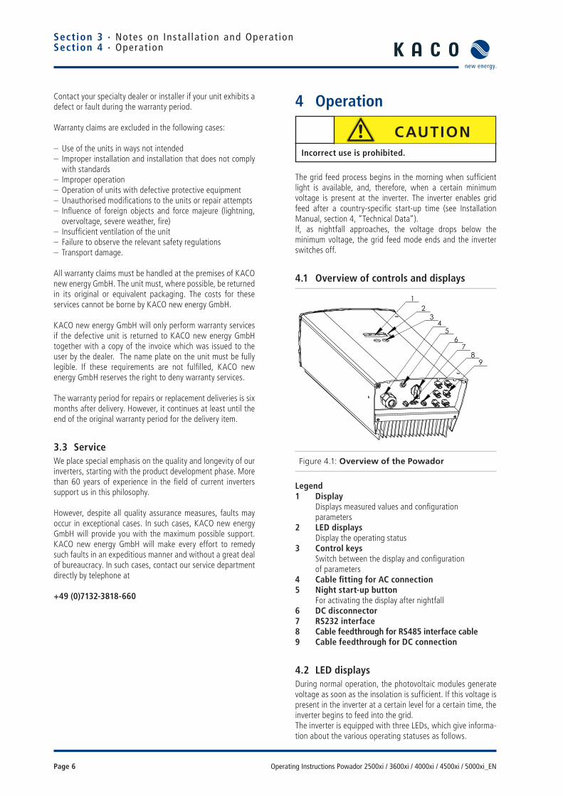
Figure 4.1: Overview of the Powador
Legend1 Display Displays measured values and confi guration parameters2 LED displays Display the operating status3 Control keys Switch between the display and confi guration of parameters4 Cable fi tting for AC connection5 Night start-up button For activating the display after nightfall6 DC disconnector 7 RS232 interface8 Cable feedthrough for RS485 interface cable9 Cable feedthrough for DC connection
4.2 LED displaysDuring normal operation, the photovoltaic modules generate voltage as soon as the insolation is suffi cient. If this voltage is present in the inverter at a certain level for a certain time, the inverter begins to feed into the grid.The inverter is equipped with three LEDs, which give informa-tion about the various operating statuses as follows.
Section 3 · Notes on Insta l la t ion and Operat ionSection 4 · Operat ion
32
1
67
98
54
CAUTIONIncorrect use is prohibited.

Operating Instructions Powador 2500xi / 3600xi / 4000xi / 4500xi / 5000xi_EN Page 7
123!
ok
Figure 4.2: LED displays
LED (1) (green):The LED begins to light up beginning with a photovoltaic module voltage of approx. 300 V and goes out again if the module voltage is lower than 250 V.The “OK” LED indicates that the inverter and the inverter con-trol are active. If this LED is not lit, the inverter cannot feed into the grid.In normal mode, the LED begins to light up in the morn-ing (if there is enough sunlight) and goes out as nightfall approaches.
LED (2) (green):The LED lights up every time the inverter feeds into the grid. For this to happen, the photovoltaic module voltage must exceed 400 V (factory setting) and suffi cient power must be provided by the PV generator. If the grid feed is interrupted because the power is too low, the inverter waits for a country-specifi c length of time before it begins feeding into the grid once again. LED (2) can, therefore, light up only when LED (1) is already lit.In a normal state, the inverter begins feeding into the grid in the morning and stops feeding into the grid as it becomes increasingly darker. On cloudy days and in the winter months, the grid feed can - depending on the PV generator and the current grid feed power - be temporarily interrupted and sub-sequently re-started. This process can repeat itself several times, especially in the morning and evening. This is in no way an indication of defective operation, but instead constitutes normal operating behaviour.
LED (3) (red):The LED indicates that the grid feed was stopped due to a fault.The following faults activate the LED (3):
– Grid overvoltage or undervoltage on one of the three phases
– Failure of one of the phases L2 or L3 – Generator power is too high – Shutdown due to the temperature being too high – Fault in the unit – Leakage current is too high (RCD type B) – Overfrequency or underfrequency – Insulation fault – Communication error – Fault in the DC grid feed – Fault in the voltage transformer – Selftest fault – Fault in the RCD type B module.
Wait approx. 10 minutes to see if the fault is only temporary in nature. If this is not the case, notify your authorised electri-cian.If the fault is cleared, the grid feed begins once again after a country-specifi c waiting period (see Installation Instructions, Section 4, “Technical Data”).
Check whether the fault in question relates to a general power failure or whether the fuse between the meter and the inverter has failed. If the fuse has failed, notify your authorised techni-cian. If there was a power failure, simply wait until the fault has been cleared. The system automatically re-starts.
4.3 Keys “1” and “2”
Figure 4.3: Powador control keys
Key “1” is used to switch between the various displays for measured values and data. With key “2”, settings such as those relating to the shutdown value can be confi gured. Here, menu navigation is divided into two levels. In level 1 (display mode), measured values such as the solar generator voltage and yields can be read. Here, only key “1” is activated. In con-fi guration mode, key “1” is also used to navigate through the individual displays, and settings are confi gured with key “2”.
Section 4 · Operat ion
IMPORTANTIf the grid feed phase fails (power failure on the public grid), LED (3) does not light up. If this happens, all LEDs and the display go out. The inverter is shut down com-pletely.The inverter can only resume its normal operation when the grid feed phase is available once again.
ACTIONBy pressing key “1” for approx. 1 second, you can choose which measured value is to be displayed. The menus are continuous, which means that when you arrive at the last entry in a menu, the fi rst entry is displayed once again the next time key “1” is pressed (see Figure 4.4).

Page 8 Operating Instructions Powador 2500xi / 3600xi / 4000xi / 4500xi / 5000xi_EN
4.4 Level 1 menu - Display menuThe display menu is displayed once the Powador inverter has started up. Measured values and all of the meters are dis-played here. Key “1” is used to navigate through the individual menu items.
Inverter type display
Start at 410 V
Generator voltage (V) and current (A)
Line voltage (V), current (A) and power (W)
Daily peak capacity
Temperature inside
Counter yield (clear using key “2”)
Yield today
Total yield
(Total) economy of CO2
Counter oper. hours (clear with key “2”)
Operating hours today
Total operating hours
Figure 4.4: Display mode menu
Powador 2500xi / 3600xi / 4000xi / 4500xi / 5000xi
The inverter waits until the voltage exceeds 410 V. One minute later, the grid feed begins.
The current voltage and current of the solar generator connected to the inverter.
The current line voltage, line current and the power that is currently being fed into the grid.
The current day’s peak power (in watts) that was fed into the grid over a short time.
A display of the current temperature inside the unit, in °C. The inverter limits the grid feed power depending on the temperature of the semiconductors.
This meter totals all yields until it is reset again. The customer can confi gure the time periods for this meter, e.g. as a monthly meter.
The power that has been fed into the grid on the current day in watt-hours (Wh).
The power that has been fed into the grid since start-up of the inverter.
Shows the CO2 savings of this PV installation compared to the German electricity mix. The CO2 savings are calculated from the total yield meter and can also be cleared with this meter.
The customer can confi gure the time periods for this meter, e.g. as a monthly meter. The procedure for resetting meters is explained at the bottom of the page.Today’s hours of operation. As soon as the inverter is in standby mode (i.e. when LED (1) lights up), the running time is added up.
Hours of operation since start-up of the inverter. As soon as the inverter is in standby mode (i.e. when LED (1) lights up), the running time is added up.
Explanation of the menu items in display mode
Section 4 · Operat ion
“Counter yield” and “Counter oper. hours” can be cleared separately from the other meters. When “Counter yield” or “Counter oper. hours” is displayed, you can reach the “Clear counter?” display by pressing key “2”. Key “2” must now be used to select “yes”. Press key “1” to confi rm the clearing. The display jumps back to the meter that was cleared. “Counter yield” and the “Counter oper. hours” are always cleared together. Therefore, clearing one meter suffi ces to clear both.

Operating Instructions Powador 2500xi / 3600xi / 4000xi / 4500xi / 5000xi_EN Page 9
4.5 Level 2 menu - Confi guration mode
Software version
Clear the grid feed meter
Select the interface and confi guration of the RS485 address
S0 interface pulse rate
Immediate start
Figure 4.5: Confi guration mode menu
Clearing the grid feed meterWhen the grid feed meter is cleared, all meters (“Counter yield”, “Yield today”, “Total yield”, “Economy of CO2”, “Daily peak capacity”, “Counter oper. hours”, “Operating hours today”, “Total operating hours”) are reset to zero. To clear the meters, select “Yes” with key “2”, and confi rm your selection by pressing key “1”. The required code is “2” and is entered using key “2”. By means of an additional con-fi rmation with key “1”, all meters are cleared. A display indi-cating that the grid feed counters have been cleared confi rms this action.
Choice of interface and address settingUsing the menu item “Interface”, you can use key “2” to switch between the RS232 and RS485 interfaces.If the RS485 interface is activated, you can reach the address setting by pressing key “1”. By pressing key “2”, the address can be set in a consecutive manner from 1 to 32.The address then jumps back to 1. The RS485 interface is used to communicate with the Powador-proLOG. When several inverters are connected to a Powador-proLOG, each address may only be used once. It is, therefore, possible to monitor 32 Powador inverters with one Powador-proLOG.
S0 interface pulse rateThe S0 interface is designed as a galvanically isolated transis-tor output. This interface is designed according to “DIN 43864 - Current interface for transmitting pulses from a pulsing meter to a tariff metering device”.The S0 interface pulse rate can be chosen in three unit inter-vals: 500, 1000 and 2000 pulses/kWh. Due to these toler-ances, the emitted pulse yield may deviate from the values on your supply grid operator’s grid feed meter by up to 15 %.
Immediate startThe inverter can also be started up without any waiting period for the purpose of testing or for the purpose of acceptance by your power supply company.If the inverter is already feeding into the grid, this menu item is not available.
Section 4 · Operat ion
ACTIONTo switch to confi guration mode, keep key “1” pressed down while at the same time pressing key “2”, until the software version is displayed in the confi guration mode. Pressing key “1” now switches to the next menu item, and changes can be made in the respective menu item by pressing key “2”. The set value increases each time key “2” is pressed. If the maximum value has been reached, the value jumps to the minimum setting choice. The vari-ous settings are highlighted in fi gure 4.5.
NOTE
Meters can only be cleared.It is not possible to set the meters.
ACTIONSettings are saved only upon exiting confi guration mode. If 2 minutes elapse without a key being pressed, the con-fi guration mode is automatically exited. The confi gura-tion mode can also be immediately exited by pressing both keys. As a confi rmation, “Settings saved” appears on the display for 4 seconds. The settings are now per-manently saved in the Powador inverter.
ACTIONKeep key “2” pressed down for a short time until the inverter switches on (relays switch audibly) and the green grid feed LED (2) lights up. If there is insuffi cient solar generator power, the inverter stops feeding into the grid after a short period of time.

Page 10 Operating Instructions Powador 2500xi / 3600xi / 4000xi / 4500xi / 5000xi_EN
4.6 DC disconnector
Figure 4.6: Underside of the Powador
The inverters include an internal DC disconnector, which allows for the inverter to be disconnected from the photo-voltaic generator in case of repair or fault.
To disconnect the inverter from the photovoltaic generator, turn the internal DC disconnector on the underside of the inverter from the ON (1) position to the OFF (0) position (see fi gure 4.6).
When delivered, the inverter’s internal DC disconnector is in the OFF (0) position.
4.7 Night start-up keyThe unit switches off in the evening as nightfall approaches. The display is no longer shown. In order to retrieve the values from the current day, (daily yield, daily hours of operation and max. grid feed power) after the display switches off, the unit can also be activated during the night by pressing the night start-up key on the underside of the inverter.
You can now scroll through the menu and retrieve the saved values. If over one minute elapses without a key being pressed, the unit switches off automatically once again.The “Counter oper. hours ”, “Total operating hours”, “Coun-ter yield”, and “Total yield” data are permanently saved and totaled. This data remains in memory even if the inverter is switched off for a long time. The daily yield, daily hours of operation and the max. daily grid feed power are available until the following morning and are cleared when PV generator voltage is present again.
4.8 The serial RS232 interfaceOperating data can be transmitted to a computer (e.g. notebook) over a galvanically isolated serial interface (see fi gure 4.6 - (7)) from where it can then be individually processed further using standard spreadsheet software.
A standard serial 1:1 interface cable is all that is required for connecting the inverter to the computer. The cable length should not exceed 20 metres.
The data from the inverter is sent unidirectionally as pure ASCII text over the serial interface. The data is not checked for errors.
Table 4.1: RS232 interface pin assignment
The RS232 interface has the following parameters:
Baud rate Data bits Parity Stop bits Protocol
9600 baud 8 none 1 none
Figure 4.7 shows, as an example, a few of lines of transmis-sion via the RS232 interface.Data can be received with any terminal emulator, which comes with every operating system, or with the KACO-viso visualisa-tion tool.
Together with the Powador inverter, KACO-viso takes over the role of a data logger. It saves the data from the inverter and displays it in various diagram types as a daily or monthly rep-resentation.The PC, however, must also run continuously. Because of the amount of energy used, this type of monitoring only makes sense over limited periods, such as during a fault analysis. For permanent monitoring, we recommend the optional accesso-ries (see section 5).
Section 4 · Operat ion
65
7
Powador Sub-D male 9-polig
Bedeutung PC Sub-D female 9-polig
2 TXD 23 RXD 34 RTS 45 GND 5
Signifi cationmale 9-pole female 9-pole
ACTIONTo do this, press the “night start-up” key (see fi gure 4.6 - (6)) on the underside of the unit for approx. 5 seconds until a display appears.
NOTE
The KACO-viso visualisation software can be down-loaded from http://www.kaco-newenergy.de
NOTE
With the optional accessories (see section 5), you can also implement wireless data transmission over long dis-tances between the inverter and your PC.

Operating Instructions Powador 2500xi / 3600xi / 4000xi / 4500xi / 5000xi_EN Page 11
Sect ion 4 · Operat ion
Table 4.2: Explanation of the individual columns
Figure 4.7: Excerpt from the protocol of a transmission via the RS232 interface
The interface of the PC or laptop that is connected must comply with the standard for RS232 interfaces. Some compu-ter manufacturers do not fully adhere to the standard. In such cases, problems may occur during data transmissions.
4.9 The RS485 interfacePowador inverters are also equipped with an RS485 interface (see Installation Instructions, fi gure 6.7) in order to enable remote monitoring of your photovoltaic installation. Several inverters can be monitored over this interface at the same time. Using the Powador-proLOG series, you can receive yield and operating data as well as error messages by SMS (text message) or e-mail. This monitoring option is especially rec-ommended for situations where you are unable to check the functionality of the installation on-site at regular intervals, e.g. if you live far away from the installation site.
In addition, you can use the Powador link within your instal-lation to bridge long distances between several inverters or between an inverter and the Powador-proLOG by means of a wireless radio transmission. Contact your installer if you wish to integrate remote monitoring into your system.
4.10 DisplayInverters in the Powador xi series are equipped with a back-lit LCD (see fi gure 4.1 - (1)) which displays measured values and data.In normal mode, the backlighting is switched off. As soon as you press one of the keys, the backlighting is activated. If approx. 1 minute elapses without a key being pressed, it switches off once again.
Spalte 1 2 3 4 5 6 7 8 9 10 00.00.0000 00:05:30 4 363.8 0.37 134 226.1 0.53 103 23 00.00.0000 00:05:40 4 366.0 0.39 142 226.1 0.53 112 23 00.00.0000 00:05:50 4 359.5 0.41 147 226.1 0.53 116 23 00.00.0000 00:06:00 4 369.8 0.42 155 226.1 0.58 118 23 00.00.0000 00:06:10 4 377.0 0.43 162 226.1 0.63 131 23 00.00.0000 00:06:20 4 373.6 0.45 168 226.1 0.63 133 23 00.00.0000 00:06:30 4 364.0 0.48 174 226.1 0.68 146 23 00.00.0000 00:06:40 4 364.3 0.49 178 226.1 0.68 146 23
Column
NOTE
The measured data for current and voltage istainted with the specifi ed tolerances (see Installation Instructions).This data is not suitable for measuring effi ciency or compiling yield data.Its sole purpose is to monitor the basic opera-tion of the system.
IMPORTANTDue to measuring tolerances, the measured values may not always correspond to the actual values. The inverter’s measuring elements have been selected to ensure maxi-mum solar yields.
Due to these tolerances, the daily yields displayed on the inverter may deviate from the values on your supply grid operator’s grid feed meter by up to 15 %.
Column Explanation Column Explanation
1 Not in use 6 Generator power in W
2 Daily operating time 7 Grid voltage in V
3 Operating mode (see table 4.3) 8 Grid current, delivered current in A
4 Generator voltage in V 9 Grid-feeding power in W
5 Generator current in A 10 Device temperature in °C

Page 12 Operating Instructions Powador 2500xi / 3600xi / 4000xi / 4500xi / 5000xi_EN
Operating statuses
Status Explanation Comment
0 Inverter has just switched on Only for a brief time after the inverter fi rst switches on in the morning.
1 Waiting to start Selftest is complete, the Powador will switch to grid feed mode in a few seconds.
2 Waiting to switch off Generator voltage and power is too low. The status before it changes over to night shutdown mode.
3 Constant voltage regulator When the grid feed begins, a constant generator voltage is fed in (80 % of the measured no-load voltage) for a short period.
4 MPP regulator, constant search movement
In cases of low insolation, the grid is fed into while the MPP regula-tor is searching.
5 MPP regulator, without search movement
In cases of high insolation, the grid is fed into while the MPP regula-tor is stationary so as to maximise yields.
6 Wait mode before grid feed, test-ing the grid and solar voltage
The inverter has stopped the grid feed because the power of the PV modules is too low (e.g. twilight). If the generator voltage is higher than the switch-on threshold (410 V), the inverter begins the grid feed once again after a country-specifi c waiting period (see Installation Instructions, section 4, Technical Data).
7 Wait mode before selftest, testing the line and solar voltage
The inverter waits until the generator voltage exceeds the switch-on threshold and begins the selftest of the relays after a country-spe-cifi cwaiting period (see Installation Instructions, section 4, Technical Data).
8 Selftest of the relays Testing line relays prior to beginning grid feed.
10 Overtemperature shutdown If the inverter overheats (heat sink temperature >85 °C) due to the ambient temperature being too high and inadequate air circulation, the inverter switches off.
11 Power limitation Protective function of the inverter when too much generator power is supplied or the heat sink of the unit exceeds 75 °C.
12 Overload shutdown Protective function of the inverter when too much generator power is supplied.
13 Overvoltage shutdown Protective function of the inverter when the line voltage L1 is too high.
14 Line failure (3-phase monitoring) Protective function of the inverter when the measured values of one of the three grid phases are beyond the permitted tolerance.Reasons for line failures are: undervoltage, overvoltage, underfre-quency, overfrequency, a fault in the phase conductor.
15 Changing over to night shutdown mode
Inverter switches from stand-by to night shutdown mode.
18 RCD type B shutdown Residual current is too high, the integrated AC/DC-sensitive residual current circuit breaker has registered an unduly high leakage current to the PE.
19 Insulation resistance too low Insulation resistance from PV-/PV+ to PE <1.2 MOhm.
30 Fault in the voltage transformer The current and voltage measurements in the inverter are not plau-sible.
31 Fault in the RCD type B module A fault has occurred in the AC/DC-sensitive residual current circuit breaker.
32 Selftest error An error has occurred during the line relay test, a line relay is not functioning correctly.
33 Fault in the DC grid feed The DC feed into the grid was too large.
34 Communication error An error has occurred in the internal data transmission.
Table 4.3: Explanation of the operating states
Section 4 · Operat ion

Operating Instructions Powador 2500xi / 3600xi / 4000xi / 4500xi / 5000xi_EN Page 13
Sect ion 4 · Operat ion
Display Explanation
Line failureUndervoltage Lx
The voltage of a grid phase is too low, the grid cannot be fed into. The phase in which the fault occurs (undervoltage) is displayed in each case.
Line failureOvervoltage Lx
The voltage of a grid phase is too high, the grid cannot be fed into. The phase in which the fault occurs (overvoltage) is displayed in each case.
Line failurePhase conductor
The phase shifts of the phase voltages are incorrect. A proper three-phase supply network is not present.
Line errorovervoltage L1
Overvoltage shutdown due to a voltage boost caused by increased line impedance of the grid connection L1.
Line failureUnderfrequency
The line frequency is too low.
Line failureOverfrequency
The line frequency is too high.
ErrorDC grid feeding
The DC feed into the grid has exceeded the permitted limit value. This grid feed can be impressed from the grid on the Powador inverter so that no inverter fault exists.
Error currentswitch-off
The current and voltage measurements in the inverter are not plausible. This can be caused by very dynamic weather conditions, if there are quick changes between low grid feed power (e.g. 200 W) and high grid feed power (e.g. the inverter’s maximum grid feed power).
ErrorRCD module
An operational fault has occurred in the AC/DC-sensitive residual current circuit breaker.
ErrorSelftest
The internal grid separation relay test has failed.
ErrorMeasurement
The current and voltage measurements in the inverter are not plausible. This can be caused by very dynamic weather conditions if there are quick changes between low grid feed power (e.g. 200 W) and high grid feed power (e.g. the maximum grid feed power).
Error isolationgenerator
The insulation resistance on the DC side is <1.2 MOhm. The grid cannot be fed into. The insulation resistance of the PV modules must be tested.
Temperature too high inside
The temperature in the unit has become too high (>85 °C). Starting from an internal temperature of 75 °C, the inverter limits the power and levels off between 75 °C and 80 °C.An internal temperature of 85 °C is only achieved if convection cooling is impeded by external factors, e.g. by covering the cooling fi ns.
FailurePV overvoltage
The power of the modules was too high for a short time. This can occur during times of very dynamic weather conditions. The power limiter usually prevents too much power at the input of the inverter so that the inverter does not shut down.
Line failureAverage voltage
The average line voltage measurement over a 10 minute period according to EN 50160 has exceeded the maximum permitted limit value.
Table 4.4: Fault signals
Fault signals

Page 14 Operating Instructions Powador 2500xi / 3600xi / 4000xi / 4500xi / 5000xi_EN
Fault signalsWhen these error messages are displayed, the grid feed is interrupted, the red LED (3) lights up, and the fault signal relay has switched. This error correction takes a country-specifi c length of time (see Installation Instructions, section 4, Tech-nical Data). Afterwards the red fault LED (3) goes out, the fault signal relay drops out again, and the display signals that it is ready to feed into the grid once again. If the fault is no longer present, the Powador inverter begins feeding into the grid once again after a preset waiting period (see Installation Instructions, section 4, Technical Data).Many of these fault signals point to a fault in the grid, and are, therefore, not an operational fault on the part of the Powa-dor inverter. The minimum triggering levels are determined by applicable standards (e.g. VDE0126-1-1), and the inverter must switch off if the permitted values are exceeded.
Automatic display during operation
Table 4.5: Display
Display Explanation
Selftestin progress
The grid separation relays are tested for proper operation.
Section 4 · Operat ion
Operating Instructions Powador 2500xi / 3600xi / 4000xi / 4500xi / 5000xi_EN Page 15
Sect ion 5 · Troubleshoot ing
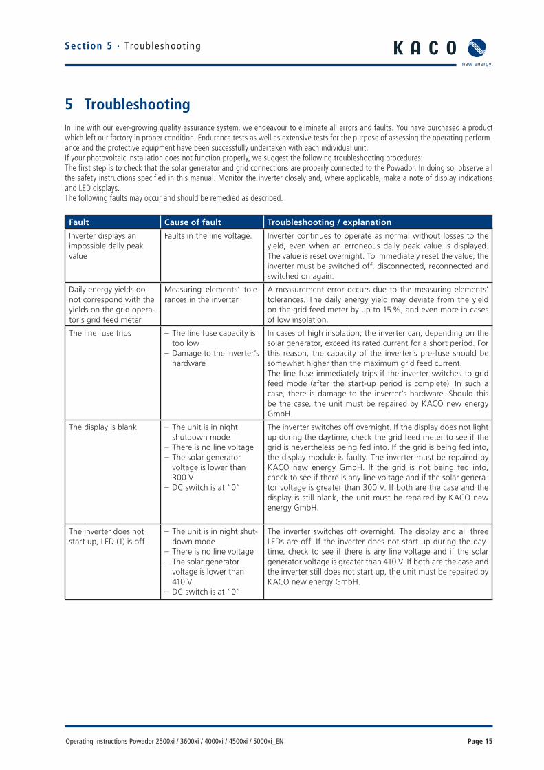
5 TroubleshootingIn line with our ever-growing quality assurance system, we endeavour to eliminate all errors and faults. You have purchased a product which left our factory in proper condition. Endurance tests as well as extensive tests for the purpose of assessing the operating perform-ance and the protective equipment have been successfully undertaken with each individual unit.If your photovoltaic installation does not function properly, we suggest the following troubleshooting procedures:The fi rst step is to check that the solar generator and grid connections are properly connected to the Powador. In doing so, observe all the safety instructions specifi ed in this manual. Monitor the inverter closely and, where applicable, make a note of display indications and LED displays. The following faults may occur and should be remedied as described.
Fault Cause of fault Troubleshooting / explanation
Inverter displays an impossible daily peak value
Faults in the line voltage. Inverter continues to operate as normal without losses to the yield, even when an erroneous daily peak value is displayed. The value is reset overnight. To immediately reset the value, the inverter must be switched off, disconnected, reconnected and switched on again.
Daily energy yields do not correspond with the yields on the grid opera-tor’s grid feed meter
Measuring elements’ tole-rances in the inverter
A measurement error occurs due to the measuring elements’ tolerances. The daily energy yield may deviate from the yield on the grid feed meter by up to 15 %, and even more in cases of low insolation.
The line fuse trips – The line fuse capacity is too low
– Damage to the inverter’s hardware
In cases of high insolation, the inverter can, depending on the solar generator, exceed its rated current for a short period. For this reason, the capacity of the inverter’s pre-fuse should be somewhat higher than the maximum grid feed current.The line fuse immediately trips if the inverter switches to grid feed mode (after the start-up period is complete). In such a case, there is damage to the inverter’s hardware. Should this be the case, the unit must be repaired by KACO new energy GmbH.
The display is blank – The unit is in night shutdown mode
– There is no line voltage – The solar generator voltage is lower than 300 V
– DC switch is at “0”
The inverter switches off overnight. If the display does not light up during the daytime, check the grid feed meter to see if the grid is nevertheless being fed into. If the grid is being fed into, the display module is faulty. The inverter must be repaired by KACO new energy GmbH. If the grid is not being fed into, check to see if there is any line voltage and if the solar genera-tor voltage is greater than 300 V. If both are the case and the display is still blank, the unit must be repaired by KACO new energy GmbH.
The inverter does not start up, LED (1) is off
– The unit is in night shut-down mode
– There is no line voltage – The solar generator voltage is lower than 410 V
– DC switch is at “0”
The inverter switches off overnight. The display and all three LEDs are off. If the inverter does not start up during the day-time, check to see if there is any line voltage and if the solar generator voltage is greater than 410 V. If both are the case and the inverter still does not start up, the unit must be repaired by KACO new energy GmbH.

Page 16 Operating Instructions Powador 2500xi / 3600xi / 4000xi / 4500xi / 5000xi_EN
Section 5 · Troubleshoot ing
The inverter is active but does not feed to the grid. Display shows: Start at 410 V meas.: xxx V
Not enough generator vol-tage available. The measu-red voltage is lower than 410 V
After sunrise, at sunset and when there is not enough solar inso-lation due to bad weather conditions, the generator voltage or the generator power that comes from the roof may be too low to be able to feed in. If the inverter has switched off because the power is too low, it waits a country-specifi c length of time (see Installation Instructions, section 4, Technical Data) before attempting to feed in once again.
The inverter is active but does not feed in – the display shows: Start at 410 V meas.: xxx V (measured voltage is greater than 410 V
The inverter has interruptedthe grid feed due to a fault.
After an interruption to the grid feed due to a fault (line fault, overtemperature, overload, etc.), the inverter waits a country-specifi c length of time (see Installation Instructions, section 4, Technical Data) before switching over to grid feed mode. With faulty grids, the inverters may even shut down during the day. Notify your solar installer if the inverter shuts down regularly over a period of several weeks (more than 10 times per day with error messages).
The inverter stops the grid feed mode shortly after being switched on, although there is suf-fi cient sunlight.
Faulty grid separation relay in the inverter
Although there is suffi cient sunlight, the inverter feeds into the grid only for a few seconds before switching off again. During the short grid feed period, the inverter shows a fed power of between 0 and 5 W. If the inverter is defi nitely receiving suf-fi cient generator power, the grid separation relay is presumably faulty, thus preventing the inverter from connecting.
Noise emission from the inverter.
Unusual ambient condi-tions
When there are unusual ambient conditions, the units may emit audible noises. The following reasons may be determining fac-tors: – Line interference or a line failure caused by particular loads (motors, machines, etc.) that are either connected to the same point on the grid or may be spatially situated nearby.
– In cases of dynamic weather conditions (frequent switching between sunny and cloudy conditions) or strong insolation, a light hum may be audible due to the increased power.
– With particular grid conditions, resonances may form between the unit’s input fi lter and the grid which may even be audible when the inverter is switched off.
– For people with very sensitive hearing (particularly children), it is possible that the high-frequency hum caused by the invert-er’s operating frequency of approx. 18 kHz is audible. Such noise emissions do not affect the operation of the inverter. They also cannot lead to reduced effi ciency, failure, deterio-ration or a shortening of the unit’s service life.
Table 5.1: Troubleshooting
If the measures described in this guide do not assist in clearing the fault, please notify your installer.In order to enable our factory customer support team to respond in an appropriate and expeditious manner, some details are imperative:
Details pertaining to the inverter – The unit’s serial number – Model – A short description of the fault – Is the error or fault reproducible? If yes, how? – Does the error or fault occur sporadically? – What type of insolation conditions existed? – Time of day
Details pertaining to the photovoltaic module – Module type, manufacturer (if available, also send the data sheet)
– The number of modules in series – The number of strings – Generator power

Operating Instructions Powador 2500xi / 3600xi / 4000xi / 4500xi / 5000xi_EN Page 17
Sect ion 6 · Recyc l ing and Disposa l
6 Recycling and DisposalFor the most part, both the inverter and the corresponding transport packaging are made from recyclable raw materials.
DeviceDo not dispose of faulty inverters or accessories in the house-hold waste. Ensure that the old unit and, where applicable, any accessories are disposed of in a proper manner.
PackagingEnsure that the transport packaging is disposed of in a proper manner.


Installation Instructions Powador 2500xi / 3600xi / 4000xi / 4500xi / 5000xi_EN Page 3
Intended for use by authorised electricians
Installation Instructions
Powador 2500xi / 3600xi / 4000xi / 4500xi / 5000xi
1 About This Documentation ........................................4
1.1 Retention of documents .............................................4
1.2 Symbols used in this document ..................................4
1.3 CE marking................................................................4
1.4 Name plate ...............................................................4
2 Safety Instructions and Regulations ..........................4
3 Notes on Installation and Operation ...........................6
3.1 Intended use .............................................................6
3.2 Factory warranty and liability .....................................6
3.3 Service ......................................................................6
4 Technical Data ...........................................................7
5 Device Description ................................................... 11
5.1 Scope of delivery ..................................................... 11
5.2 Dimensioning the PV generator ................................ 11
5.3 Protection concepts .................................................12
6 Installation and Start-up ..........................................12
6.1 Selecting an appropriate place for installation ..........12
6.2 Installing the inverter ...............................................13
6.3 Electrical connection ................................................13
6.4 Connecting the fault signal relay ..............................17
6.5 The S0 output connection ........................................17
6.6 The RS485 interface connection ..............................17
6.7 Starting up the inverter ............................................17
6.8 Programming - Confi guration mode menu................18
7 Switching the Inverter Off ........................................19
8 Powador as Part of a PV Installation ........................20
8.1 Design of installation ...............................................20
8.2 Installation with multiple inverters ...........................22
8.3 Notes specifi c to the Powador 5000xi ......................23
9 Documents ..............................................................24
9.1 EU Declaration of Conformity ...................................24
9.2 Declaration of Conformity ........................................25

Page 4 Installation Instructions Powador 2500xi / 3600xi / 4000xi / 4500xi / 5000xi_EN
1 About This DocumentationThe following notes guide you through all of the documenta-tion. Additional documents are applicable in conjunction with these operating and installation instructions.
We assume no liability for any damage caused by failure to observe these instructions.
Other applicable documentsWhen installing the inverters, be sure to observe all assembly and installation instructions for components and other parts of the system. These instructions are delivered together with the respective components and additional parts of the system.
1.1 Retention of documentsPlease pass these operating and installation instructions on to the plant operator. The plant operator retains the docu-ments. The instructions must be available whenever they are needed.
1.2 Symbols used in this documentWhen installing the inverter, observe the safety instructions provided in these installation instructions.
Danger due to lethal voltages.
Risk of fatal injury from fi re or explosions.
Risk of burns from hot housing components.
Disconnect the inverter from all power sources
1.3 CE markingThe CE marking is used to document that the Powador inverter shown on the name plate fulfi lls the fundamental require-ments of the following relevant directives: – Directive concerning electromagnetic compatibility(Council Directive 2004/108/EC)
– Low Voltage Directive (Council Directive 2006/95/EC).
1.4 Name plateThe name plate showing the exact designation of the unit is located on the support plate on the underside of the housing.
Section 1 · About Th is Documentat ionSection 2 · Safety Inst ruct ions and Regulat ions
DANGER
Failure to observe a warning indicated in this manner will directly lead to serious bodily injury or death.
Failure to observe a warning indicated in this manner may directly lead to serious bodily injury or death.
WARNING
CAUTIONFailure to observe a warning indicated in this manner may lead to minor or moderate bodily injury or to serious damage to property.
ATTENTION
Failure to observe a warning indicated in this manner may lead to damage to property.
NOTE
Useful information and notes.
ACTION
This symbol indicates that a certain action is required.
IMPORTANT
Failure to observe this information may result in reduced convenience or impaired functionality.

Installation Instructions Powador 2500xi / 3600xi / 4000xi / 4500xi / 5000xi_EN Page 5
2 Safety Instructions and Regulations
Standards and regulationsIEC 60364-7-712:2002:Requirements for special installations or locations – Solar pho-tovoltaic (PV) power supply systems.
Technical rulesThe installation must be suited to the on-site conditions and comply with local regulations and technical rules.
Accident prevention regulationsThe inverter must be installed by an authorised, skilled electri-cian who is approved by the supply grid operator. The electri-cian is responsible for observing existing standards and regu-lations.
The proper and safe operation of this unit requires proper transportation, storage, assembly and installation, as well as careful operation and maintenance.
Only skilled electricians who have read and fully understood all safety instructions contained in these operating and instal-lation instructions, as well as other instructions concerning assembly, operation and maintenance, may work on this unit.
When the unit is operating, certain parts of the unit unavoid-ably carry hazardous voltages, which can lead to death or seri-ous bodily injury. The precautions listed below must be fol-lowed in order to minimise the risk of death or injury.
– The unit must be installed in compliance with safety regula-tions as well as all other relevant national or local regula-tions. To ensure operational safety, proper earthing, con-ductor dimensioning and appropriate protection against short circuiting must be provided.
– All covers on the unit must remain closed during opera-tion.
– Prior to performing any visual inspections or maintenance, ensure that the power supply has been switched off and is prevented from being inadvertently switched back on. If measurements must be taken while the power supply is switched on, never touch the electrical connections. Remove all jewellery from your wrists and fi ngers. Ensure that the testing equipment is in good and safe operating condition.
– When working on the unit while it is switched on, stand on an insulated surface, thus ensuring that there is no earthed connection.
– Follow the instructions contained in these operating and installation instructions exactly, and observe all danger, warning and caution information.
– This list does not constitute a complete listing of all meas-ures required for the safe operation of the unit. Contact your specialty dealer if any specifi c problems arise which are not suffi ciently covered for the purposes of the buyer.
Modifi cationsModifi cations to the inverter are generally prohibited. Changes to the surroundings of the inverter are only permitted if they comply with national standards.
TransportationThe inverter is subjected to extensive testing and inspections in our test fi eld. This is how we ensure the high quality of our products. Our inverters leave our factory in proper electrical and mechanical condition. Special packaging provides for a safe and careful transportation. However, transport damage may still occur. The shipping company is responsible in such cases.
Thoroughly inspect the inverter upon delivery. If you discover any damage to the packaging which indicates that the inverter may have been damaged, or if you discover any visible damage to the inverter, notify the responsible shipping company imme-diately.
If necessary, KACO new energy GmbH will assist you. Damage reports must be received by the shipping company in writing within six days of receipt of the goods.
When transporting the inverter, only the original packaging is to be used, as this provides for a safe transportation.
Section 2 · Safety Inst ruct ions and Regulat ions
DANGERDanger due to lethal voltages.
Lethal voltages are present within the unit and on the power supply lines. Therefore, only skilled and authorised electricians may install and open the unit.
Even when the unit is switched off, high contact voltages may still be present inside the unit.
CAUTIONRisk of damage due to improper modifi cations.Never modify or manipulate the inverter or other components of the system.

Page 6 Installation Instructions Powador 2500xi / 3600xi / 4000xi / 4500xi / 5000xi_EN
3 Notes on Installation and Operation
3.1 Intended useThe Powador inverter converts the DC power generated by the photovoltaic (PV) modules into AC power and feeds this into the power grid.Powador inverters are built according to the state of the art and recognised safety rules. However, improper use may cause lethal hazards for the operator or third parties, or may result in damage to the units and other property. The inverter may only be operated with a permanent connec-tion to the public power grid. The inverter is not intended for mobile use.
Any other or additional use is not considered the intended use. The manufacturer/supplier is not liable for damage caused by such unintended use. Damage caused by such unintended use is at the sole risk of the operator.Intended use also includes adherence to the operating and installation instructions. Some of the documents that you require in order to register your photovoltaic installation and have it approved are included in the installation instructions (see section 9).
3.2 Factory warranty and liabilityKACO new energy GmbH issues a warranty of seven years on the Powador inverter starting from the date of installation, but at most 90 months after shipment by KACO new energy GmbH.
During this time, KACO new energy GmbH guarantees the proper operation of the units and to undertake repairs at the factory free of charge in the event of a defect for which we are responsible.
Contact your specialty dealer if your unit exhibits a defect or fault during the warranty period.
Warranty claims are excluded in the following cases: – Use of the units in ways not intended – Improper installation and installation that does not comply with standards
– Improper operation – Operation of units with defective protective equipment – Unauthorised modifi cations to the units or repair attempts – Infl uence of foreign objects and force majeure (lightning, overvoltage, severe weather, fi re)
– Insuffi cient ventilation of the unit – Failure to observe the relevant safety regulations – Transport damage.
All warranty claims must be handled at the premises of KACO new energy GmbH. The unit must, where possible, be returned in its original or equivalent packaging. The costs for these services cannot be borne by KACO new energy GmbH.
KACO new energy GmbH will only perform warranty services if the defective unit is returned to KACO new energy GmbH together with a copy of the invoice which was issued to the user by the dealer. The name plate on the unit must be fully legible. If these requirements are not fulfi lled, KACO new energy GmbH reserves the right to deny warranty services.
The warranty period for repairs or replacement deliveries is six months after delivery. However, it continues at least until the end of the original warranty period for the delivery item.
3.3 ServiceWe place special emphasis on the quality and longevity of our inverters, starting with the product development phase.. More than 60 years of experience in the fi eld of current inverters support us in this philosophy.
However, despite all quality assurance measures, faults may occur in exceptional cases. In such cases, KACO new energy GmbH will provide you with the maximum possible support. KACO new energy GmbH will make every effort to remedy such faults in an expeditious manner and without a great deal of bureaucracy. In such cases, contact our service department directly.
Telephone +49 (0)7132-3818-660
Section 3 · Notes on Insta l la t ion and Operat ion

Installation Instructions Powador 2500xi / 3600xi / 4000xi / 4500xi / 5000xi_EN Page 7
Sect ion 4 · Technica l Data
4 Technical Data
Input - Electrical data
Model 2500xi 3600xi 4000xi 4500xi 5000xi
DC rated power 2710 W 3600 W 4600 W 4800 W 5730 W
Max. PV generator power 3200 W 4400 W 5250 W 6000 W 6800 W
MPP range 350 ... 600 V
No-load voltage Max. 800 V
Monitoring input voltage Stand-by from Ue > 300 VNight shutdown from Ue < 250 V
DC voltage ripple < 3 % eff
Max. DC input current 8.6 A 12.0 A 14.5 A 15.2 A 18.0 A
Polarity safeguard Short-circuit diode
Output - Electrical data
Model 2500xi 3600xi 4000xi 4500xi 5000xi
AC rated power 2600 W 3600 W 4400 W 4600 W 5500 W
Maximum power AC 2850 W 4000 W 4800 W 5060 W 6000 W
Line voltage See section 4 - Technical Data - Country-specifi c parameters - page 9
Rated current 11.3 A 15.6 A 19.1 A 20.0 A 23.9 A
Max. current 12.4 A 17.5 A 20.9 A 22.0 A 26.0 A
Power factor ≈1
Frequency See section 4 - Technical Data - Country-specifi c parameters - page 9
Distortion factoraccording to EN 61000-3-2
<3 % at rated power<5 % over the entire range
Fault signal relay Potential-free NO contact (make contact), max. 30 V / 1 A
S0 output Open collector – output max. 30 V / 50 mA
Page 8 Installation Instructions Powador 2500xi / 3600xi / 4000xi / 4500xi / 5000xi_EN
Section 4 · Technical Data
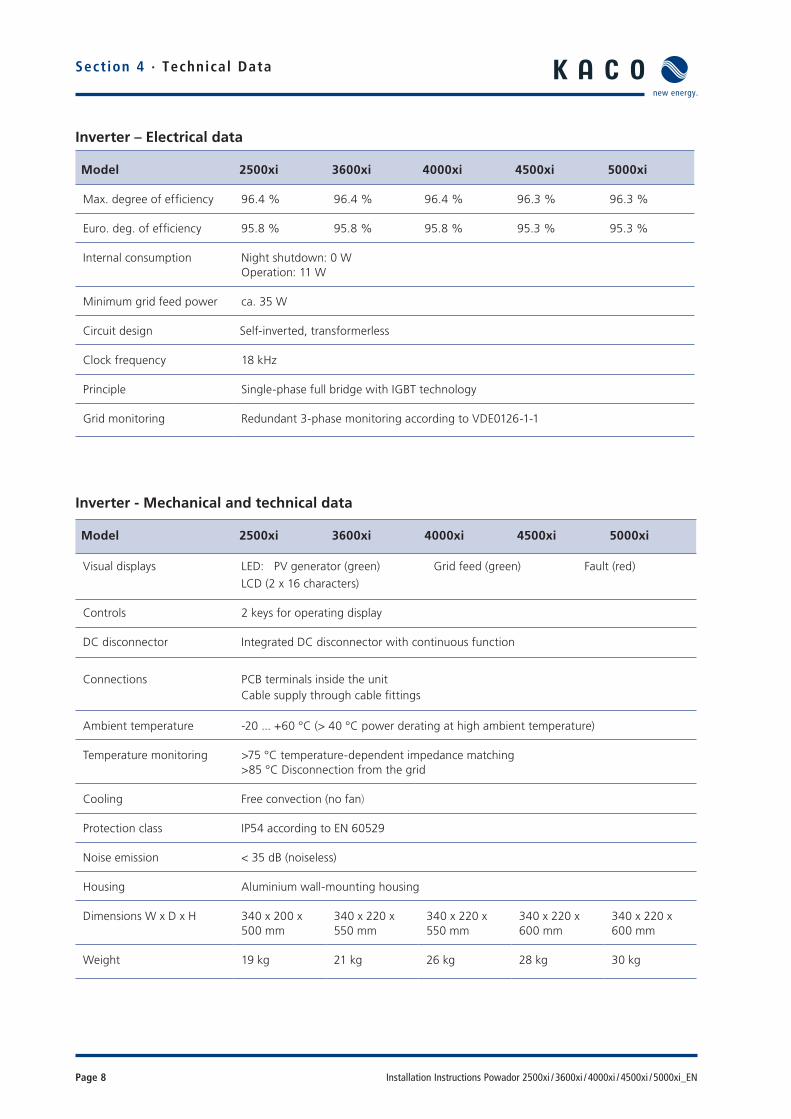
Inverter – Electrical data
Model 2500xi 3600xi 4000xi 4500xi 5000xi
Max. degree of effi ciency 96.4 % 96.4 % 96.4 % 96.3 % 96.3 %
Euro. deg. of effi ciency 95.8 % 95.8 % 95.8 % 95.3 % 95.3 %
Internal consumption Night shutdown: 0 WOperation: 11 W
Minimum grid feed power ca. 35 W
Circuit design Self-inverted, transformerless
Clock frequency 18 kHz
Principle Single-phase full bridge with IGBT technology
Grid monitoring Redundant 3-phase monitoring according to VDE0126-1-1
Inverter - Mechanical and technical data
Model 2500xi 3600xi 4000xi 4500xi 5000xi
Visual displays LED: PV generator (green) Grid feed (green) Fault (red)LCD (2 x 16 characters)
Controls 2 keys for operating display
DC disconnector Integrated DC disconnector with continuous function
Connections PCB terminals inside the unitCable supply through cable fi ttings
Ambient temperature -20 ... +60 °C (> 40 °C power derating at high ambient temperature)
Temperature monitoring >75 °C temperature-dependent impedance matching>85 °C Disconnection from the grid
Cooling Free convection (no fan)
Protection class IP54 according to EN 60529
Noise emission < 35 dB (noiseless)
Housing Aluminium wall-mounting housing
Dimensions W x D x H 340 x 200 x 500 mm
340 x 220 x 550 mm
340 x 220 x 550 mm
340 x 220 x 600 mm
340 x 220 x 600 mm
Weight 19 kg 21 kg 26 kg 28 kg 30 kg

Installation Instructions Powador 2500xi / 3600xi / 4000xi / 4500xi / 5000xi_EN Page 9
Country-specifi c setting of parameters
Parameter
Country
Linevoltagerange[V]
Linevoltageaccordingto EN 50160[V]
Standard frequencyrange[Hz]
Start-up valueafter are-start[s]
Reset time afterinsuffi cientgrid feed power[s]
Reset timeafter a fault[s]
Germany 190 ... 264 253 V 47.5 ... 50.2 > 60 > 180 > 30
Spain 196 ... 254 - 49.0 ... 51.0 > 180 > 180 > 180
Italy 190 ... 264 - 49.7 ... 50.3 > 180 > 180 > 30
France 190 ... 264 253 V 49.5 ... 50.5 > 60 > 180 > 30
Cyprus (GR) 208 ... 252 - 49.5 ... 50.5 > 180 > 180 > 180
Greece 190 ... 264 - 49.5 ... 50.5 > 180 > 180 > 180
South Korea 194 ... 242 - 59.3 ... 60.5 > 360 > 360 > 360
Czech Republic 196 ... 252 253 V 49.5 ... 50.5 > 60 > 180 > 30
Portugal 196 ... 264 - 47.0 ... 51.0 > 60 > 180 > 30
Bulgaria 196 ... 264 - 47.0 ... 51.0 > 60 > 180 > 30
The switch-on times after a re-start, a fault or after insuffi cient grid feed power are approximate values.
Section 4 · Technica l Data
Parameter
Country
L 1 L 2 L 3 N PE Comment
Germany X X X X X With phase conductor monitoring
Spain X X X
Italy X X X
France X X X X X
Cyprus (GR) X X X
Greece X X X
South Korea X X X
Czech Republic X X X X X With phase conductor monitoring
Portugal X X X
Bulgaria X X X
Country-specifi c grid connection table
Page 10 Installation Instructions Powador 2500xi / 3600xi / 4000xi / 4500xi / 5000xi_EN
Section 4 · Technical Data
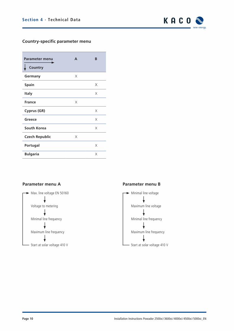
Country-specifi c parameter menu
Parameter menu
Country
A B
Germany X
Spain X
Italy X
France X
Cyprus (GR) X
Greece X
South Korea X
Czech Republic X
Portugal X
Bulgaria X
Parameter menu A
Max. line voltage EN 50160
Voltage to metering
Minimal line frequency
Maximum line frequency
Start at solar voltage 410 V
Parameter menu B
Minimal line voltage
Maximum line voltage
Minimal line frequency
Maximum line frequency
Start at solar voltage 410 V
Installation Instructions Powador 2500xi / 3600xi / 4000xi / 4500xi / 5000xi_EN Page 11
5 Device Description
The transformerless Powador xi units are currently available for fi ve different power ratings. The appropriate inverter type is selected according to the maximum output of the pho-tovoltaic modules that have been installed. The maximum output values can be found in the data sheet (see Technical Data, section 4).Your inverter’s designation is located on the front side, above the display and on the name plate.
5.1 Scope of delivery – Powador – Wall bracket – Installation kit – Documentation
5.2 Dimensioning the PV generatorThe selection of the PV generator is of central importance when dimensioning a PV installation. When doing so, you must be sure that the solar generator is also compatible with the inverter.Observe the data provided in the data sheet (see Technical Data, section 4) when dimensioning the solar generator.
Dimensioning the PV generatorThe number of PV modules connected in series must be selected in such a way that the output voltage of the PV gen-erator stays within the permitted input voltage range of the inverter - even during extreme outside temperatures. In Cen-tral Europe, module temperatures between -10 °C and +70 °Cshould be assumed. Depending on the way in which the modules are installed and the geographic location, +60 °C or +70 °Cshould be used when calculating the voltage. The tempera-ture coeffi cients of the solar modules should be taken into account. The following criteria must be met for calculating the voltage of the PV generator:
– U0 (-10 °C) < max. input voltage (800 V). Even at very low outside temperatures (-10 °C), the no-load voltage of the connected string must lie within the permitted input volt-age range. If the temperature falls from 25 °C to -10 °C,the no-load voltage in 12 V modules increases by approx. 2.8 V per module (5.6 V for a 24 V module). The no-load voltage of the entire string must be less than 800 V .
– UMpp (+60 °C) > min. input voltage (350 V). Even at very high outside temperatures (+60 °C), the MPP voltage of the connected string should lie within the permitted input voltage range. If the temperature increases from 25 °C to60 °C, the MPP voltage in 12 V modules decreases by approx. 3.6 V per module (7.2 V for a 24 V module). The MPP voltage of the entire string should be at least 350 V.
If the MPP voltage moves outside of the permitted input range, the installation still functions properly. In this situation, the maximum possible amount of power is not fed into the grid; instead, a small amount less is fed.
Provided that the input voltage is within the permitted input voltage range, the inverter will not be damaged if a connected PC generator provides current that is above the max. usable input current.If the PV generator briefl y provides more than the inverter’s max. PV generator power, especially with changing cloud cover and relatively low module temperatures, the inverter may switch off due to safety reasons and automatically switch on again after a country-specifi c waiting period (see section 4, Technical Data). The overload status is shown by a red LED and as plain text on the display. Under normal circumstances, the dynamic control of the inverter ensures that the inverter continues to operate without interruption.
The solar generator still represents the largest factor in the cost of a solar installation. For this reason, it is extremely important to obtain maximum energy yields from the solar generator. To achieve this, solar generators in Central Europe should be oriented to the south at an angle of inclination of 30°. They should never be shaded.
This orientation is quite often not possible due to structural reasons. In order to achieve the same energy yield as an opti-mally oriented solar generator (south, 30° angle of inclina-tion), the solar generator power can be increased. For roofs with an east-west orientation, we recommend a two-string PV installation. To achieve an optimum yield from the installation, the fi rst string must be installed on the east side of the roof; the second string on the west side. For exposed locations in mountains or in southern regions, we recommend that the power generator be reduced appro-priately. Please consult with us or your specialty dealer about this matter.
Section 5 · Device Descr ipt ion
CAUTIONIncorrect use is prohibited.
NOTEKACOCALC Pro, a dimensioning program for the easy selection of PV modules, can be downloaded at no cost at the following address: http://www.kaco-newenergy.de
Page 12 Installation Instructions Powador 2500xi / 3600xi / 4000xi / 4500xi / 5000xi_EN
5.3 Protection concepts
The following monitoring and protective functions are inte-grated into Powador inverters: – Redundant 3-phase grid monitoring in order to protect the operator and to avoid islanding.
– Overvoltage conductors/varistors to protect the power sem-iconductors from high-energy transients on the grid side.
– Temperature monitoring of the heat sink. – EMC fi lters to protect the inverter against high-frequency line interference.
– AC/DC-sensitive residual current circuit breaker RCD type B switch (Residual Current protective Device), which monitors the leakage current from the Powador’s grid connection to the PV generator and interrupts the feed to the grid when the residual current exceeds 30 mA. The RCD type B switch triggers when a cable has a fault in the insulation, a frame fault or an earth fault.
6 Installation and Start-up
6.1 Selecting an appropriate place for installation
The units should be installed in areas that are as dry as pos-sible in order to extend their service life. In addition, be sure that the units are installed in climate-controlled areas in order to protect them from overheating. This extends their service life.
When selecting the inverter’s place of installation, attention should be paid to the following items: – Ensure good access to the unit for installation or any service work that may later be required.
– Maintain the following minimum clearances around the unit:
200 mm side clearance to other units, 700 mm clearance to other stacked units, 500 mm to cabinets, ceilings, etc.
– The unit has been designed for vertical wall installation. – Air must be allowed to circulate freely around the housing and through the heat sink on the rear side.
Section 5 · Device Descr ipt ionSection 6 · Ins ta l la t ion and Star t -up
Risk of fatal injury from fi re or explosions.The Powador’s housing may become hot during operation.
Do not mount the Powador on fl ammablematerials.
Do not install the Powador in areas which con-tain highly fl ammable materials.
Do not install the Powador in areas where there is a risk of explosion.
WARNING
CAUTIONRisk of burns from hot housing components.Install the Powador so that unintentional contact with it is not possible.
NOTEPowador inverters meet the requirements of protection class IP54 if all cable feedthroughs are used or suitably closed off.
Installation Instructions Powador 2500xi / 3600xi / 4000xi / 4500xi / 5000xi_EN Page 13
– If the inverter is built into a switching cabinet or similar, provide forced ventilation to insure that heat is suffi ciently dissipated.
– The heat sink may reach a max. temperature of 90 °C. There-fore, mount the inverter only on walls made from heat-resist-ant material.
– Ensure that the wall has adequate load-bearing capacity and use appropriate installation material.
– In areas prone to fl ooding, be sure to install the inverter in a suffi ciently elevated place.
– Installation at eye level makes it easier to read the display.
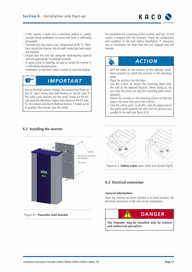
6.2 Installing the inverter
Figure 6.1: Powador wall bracket
An installation kit consisting of four anchors and four 70 mm screws is shipped with the inverters. Check the composition and condition of the wall before installation. If necessary, use an installation kit other than the one shipped with the inverter.
Figure 6.2: Safety catch open (left) and closed (right)
6.3 Electrical connection
General informationAfter the inverter has been installed in its fi xed location, the electrical connection to the unit can be established.
Section 6 · Ins ta l la t ion and Star t -up
Anchor
Notches for mountingthe Powador
M5 screw
IMPORTANT
Due to the high system voltage, the current that fl ows on the DC side is lower than that fl owing on the AC side. If the cable cross-sections are the same, losses on the AC-side lead are, therefore, higher than those on the DC side. For this reason and due to thermal factors, it makes sense to position the inverter near the meter.
ACTION
– Drill the holes for the anchors at the selected instal-lation position to match the cut-outs in the mounting plate.
– Place the anchors into the holes. – Use the screws to mount the mounting plate onto the wall at the selected location. When doing so, be sure that the arrow cut into the mounting plate points upwards.
– Mount the inverter on the mounting fi xture so that the pegs in the heat sink rest in the notches.
– Lock the safety catch. To do this, slide the upper end of the safety catch towards the wall until the groove runs parallel to the wall (see fi gure 6.2).
DANGER
The Powador may be installed only by trained and authorised specialists.

Page 14 Installation Instructions Powador 2500xi / 3600xi / 4000xi / 4500xi / 5000xi_EN
All mandatory safety regulations, the currently required tech-nical connection specifi cations of the responsible electrical supply company, as well as other generally applicable local regulations are to be adhered to.
When connecting the inverter, the AC and DC sides must be disconnected from all power sources and secured against being inadvertently switched back on. The connection of the PV generator and the grid connection are established via PCB terminals in the connection box of the inverter (see fi gure 6.3).
Figure 6.3: Powador connection box
AC/DC-sensitive residual current circuit breakerRCD type B
The inverter is equipped with an AC/DC-sensitive residual cur-rent circuit breaker. If there is an impermissible residual cur-rent, the inverter is disconnected from the grid. An external residual current circuit breaker is, in compliance with the appli-cable directives in the respective country, not required if a cor-responding low-resistance earthing of the unit is possible.
Grid connectionThe inverter feeds in single-phased at terminal L1. However, the grid connection is established in various ways, depend-ing on the country (see section 4, Technical Data). There is an appropriate cable fi tting on the underside of the housing for inserting the leads.
We recommend the following conductor cross-sections for cable lengths up to 20 m: – Powador 2500xi / 3600xi: 2.5 mm² – Powador 4000xi: 4.0 mm² – Powador 4500xi / 5000xi: 6.0 mm²
Larger cross sections should be used for longer leads.
In accordance with VDE 0100 part 430 “Protection of cables and cords against overcurrent”, when NYM cables are per-manently laid, with an ambient temperature in the B2 laying system (multi-conductor lead in the pipe or duct, either on or in walls or fl ush-mounted) of 25 °C, the cables should be secured as follows: – 2.5 mm² 20 A – 4 mm² 25 A – 6 mm² 35 A
NEOZED fuses (gL) should be used.
Section 6 · Ins ta l la t ion and Star t -up
ACTION
The door of the housing must be opened to do this. The door is held shut with two Phillips recessed-head screws on the front of the housing.
NOTEAt the AC and DC connection terminals, the maximum conductor cross-section that can be connected is 10 mm² for fl exible conductors and 16 mm² for rigid conductors. Strip off 10 mm of insulation. Tighten the terminal with a torque of 1.2 to 1.5 Nm. NOTE
Be sure to use cables with a suffi ciently large cross-sec-tion to avoid excessive line impedance between the building’s distribution box and the respective Powador unit.
When the line impedance is high, i.e. long AC-side leads, the voltage at the line terminals of the inverter will increase as power is being fed in to the grid. The inverter measures this voltage. If the voltage at the line terminals exceeds the line overvoltage limit, the inverter will switch off due to line overvoltage. This must be taken into con-sideration when wiring the AC and dimensioning the AC lead.
DANGER
Risk of electric shock at live connections.Check that the power lead is voltage-free before inserting it into the unit.
Installation Instructions Powador 2500xi / 3600xi / 4000xi / 4500xi / 5000xi_EN Page 15
PV generator connectionThe PV generator leads are connected in the connection box on the right side.
The PV generator can be connected in the following ways:
– Cable fi ttings – Tyco plug connectors – MC plug connectors
When delivered, the cable fi ttings are already installed. As an option, Tyco and MC plug connectors can be delivered with the inverter.
Section 6 · Ins ta l la t ion and Star t -up
ACTION
Guide the lead, which has been stripped of its jacket and insulation, through the cable fi tting.Connect the lead, which has been stripped of its jacket and insulation, as is shown on the label on the left side of the PCB terminal.
CAUTION
Check that the leads are properly connected. Exchanging L and N will destroy the inverter.
ACTION
Once again, check that all connected leads are fi rmly connected.Tighten the cable seal of the cable fi tting.
DANGER
To ensure maximum protection against hazardous contact voltages while assembling photovoltaic installations, both the positive and the negative leads must be strictly isolated electrically from the earth potential (PE).
ATTENTION
Risk of damage.Ensure that the polarity is correct when connecting the unit.
ACTION
Before connecting the PV generator to the Powador, check that the PV generator is not earthed. – Measure the DC voltage between the protective earth (PE) and the positive lead and between the protec-tive earth (PE) and the negative lead of the PV gen-erator.If stable voltages can be measured, there is an earth fault in the PV generator or its wiring. The ratio between the measured voltages gives an indication as to the location of this fault. This fault must be rem-edied before taking any further measurements.
– Measure the electrical resistance using a tester accord-ing to DIN VDE0100 (a megohmmeter) between the protective earth (PE) and the positive lead and the protective earth (PE) and the negative lead of the PV generator.
Low resistance (< 2 MΩ) indicates a high-ohm earth fault of the PV generator, which must be remedied before further installation.
CAUTIONThe voltage of the solar generator must be meas-ured before connecting the DC leads to the inverter terminals. The DC voltage must not exceed 800 V. Connecting to a higher voltage will destroy the unit.

Page 16 Installation Instructions Powador 2500xi / 3600xi / 4000xi / 4500xi / 5000xi_EN
Connecting the PV generator using cable fi ttings
Connecting the PV generator using MC or Tyco plug connectorsAs an option, MC and Tyco plug connectors can be delivered with the inverter. These can be used instead of the cable fi t-tings that were already installed upon delivery. These pre-installed cable fi ttings must fi rst be removed before installing the appropriate plug connectors.
Figure 6.4: Installing Tyco sockets
The assembly of the Tyco and MC plug connectors is shown in fi gure 6.5 and fi gure 6.6 respectively.
Figure 6.5: Assembly of the Tyco plug connectors
Figure 6.6: Assembly of the MC plug connectors
Section 6 · Ins ta l la t ion and Star t -up
ATTENTIONTo achieve protection class IP54, unused cable fi ttings must be closed off by using the included blind caps.
ACTION
To do this, unscrew the cable fi ttings until you can insert the cables through the fi tting, and screw the ends of the cables into place in the connection terminals labelled “PV+” and “PV-”. When doing this, ensure that the polarity is correct. Tighten the cap of the cable fi tting.
Always disconnect the inverter from the PV gen-erator by operating the integrated DC disconnec-tor before pulling apart the plug connector. Fail-ure to observe this may cause arcing, which can result in a hazard to health and to the unit.
WARNING
ACTION
Unscrew the cable fi ttings from the cut-outs in the base plate of the inverter.Insert the Tyco or MC sockets from the outside through the cut-outs, and secure them from the inside using the black plastic nut.
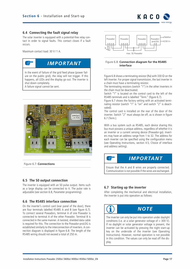
Installation Instructions Powador 2500xi / 3600xi / 4000xi / 4500xi / 5000xi_EN Page 17
Figure 6.8: Connection diagram for the RS485 interface
Figure 6.8 shows a terminating resistor (Ra) with 330 Ω on the left inverter. For proper signal transmission, the last inverter in a chain must have a terminating resistor. The terminating resistors (switch “1”) in the other inverters in the chain must be deactivated.Switch “1” is located on the control card to the left of the RS485 terminals and is labelled “Term.” (fi gure 6.7).Figure 6.7 shows the factory setting with an activated termi-nating resistor (switch “1” is “on” and switch “2” is deacti-vated).The control card is installed on the rear of the door of the inverter. Switch “2” must always be off, as is shown in fi gure 6.7 (Term.).
With a bus system such as RS485, each device sharing this bus must possess a unique address, regardless of whether it is an inverter or a current sensing device (Powador-go). Invert-ers may have an address range from 1 to 32. The address for each inverter can be specifi ed using the confi guration menu (see Operating Instructions, section 4.5, Choice of interface and address setting).
6.7 Starting up the inverterAfter completing the mechanical and electrical installation, the inverter is put into operation as follows:
6.4 Connecting the fault signal relayThe solar inverter is equipped with a potential-free relay con-tact in order to signal faults. This contact closes if a fault occurs.
Maximum contact load: 30 V / 1 A.
Figure 6.7: Connections
6.5 The S0 output connectionThe inverter is equipped with an S0 pulse output. Items such as a large display can be connected to it. The pulse rate is adjustable (see section 6.8, Parameter programming).
6.6 The RS485 interface connectionOn the inverter’s control card (rear panel of the door), there are four terminals labelled RS485 A and B (see fi gure 6.7). To connect several Powadors, terminal A of one Powador is connected to terminal A of the other Powador. Terminal B is connected in the same manner. A twisted, shielded data cable is required for this. The connection to the Powador-proLOG is established similarly to the interconnection of inverters. A con-nection diagram is displayed in fi gure 6.8. The length of the RS485 wiring should not exceed a total of 250 m.
Section 6 · Ins ta l la t ion and Star t -up
IMPORTANT
In the event of failure of the grid feed phase (power fail-ure on the public grid), the relay will not trigger. If this happens, all LEDs and the display go out. The inverter is shut down completely.A failure signal cannot be sent.
IMPORTANT
Ensure that the A and B wires are properly connected. Communication is not possible if the wires are exchanged.
NOTE
The inverter can only be put into operation under daylight conditions (i.e. at a solar generator voltage of > 300 V). If no daylight or solar generator voltage is present, the inverter can be activated by pressing the night start-up key on the underside of the inverter (see Operating Instructions). However, normal operation is not possible in this condition. The values can only be read off the dis-play.
Telefon
230 V~Powador-proLOG
A B
Powador
A B A B
Powador
A B A B
Powador
A B A B
Ra
max. 32 Powador

Page 18 Installation Instructions Powador 2500xi / 3600xi / 4000xi / 4500xi / 5000xi_EN
6.8 Programming - Confi guration mode menu
Various operating mode parameters can be set in the confi gu-ration mode menu of Powador xi units.
In order to switch to the confi guration mode menu, hold key “2” pressed down for 15 seconds until the display changes and displays the fi rst parameter.
Use key “1” to scroll through the various menu items. The menu is continuous. When you reach the end, the display automatically jumps back to the fi rst item.
The parameter menu is country-specifi c.Details can be found in: – Section 4 – Technical Data – Country-specifi c parameters.
Figure 6.9: Confi guration mode menu
The uppermost green LED (1) lights up if the generator volt-age is greater than 300 V. The display now shows the inverter type for 4 seconds, followed by the current generator volt-age: “Start at 410 V meas.: xxx V”. If the measured voltage is greater than 410 V, the unit begins feeding into the grid after a country-specifi c time period (see section 4, Technical Data). This country-specifi c start-up period is required in order to ensure that the generator voltage is continuously above the power delivery limit of 410 V. An quick start routine is pro-vided for start-up and test purposes. This routine circumvents the start-up period. This quick start routine is found in the confi guration mode menu (see Operating Instructions).
During the start-up procedure, the line power relay audibly switches on and power delivery starts. This is signalled by the green LED (2). The display now shows the power being fed to the grid. Key “1” can now be used to display the various measured values (see Operating Instructions).
If the inverter stops feeding into the grid because the power is too low, it waits a country-specifi c length of time before resuming power delivery (see section 4,Technical Data).
Quick startThe inverter can also be started up without any waiting period for the purpose of testing or for the purpose of acceptance by your power supply company.
Section 6 · Ins ta l la t ion and Star t -up
ACTION
– Switch on the line voltage (via the external circuit breakers).
– Switch on the solar generator using the DC disconnec-tor (0 → 1).
ACTION
To do this, switch to the confi guration mode menu by pressing both keys at the same time. Press key “1” to move through the menu until you have reached the “Quick start with key 2” menu item.When you have reached this menu item, keep key “2” pressed down for a short time until the inverter switches on (relays switch audibly) and the green grid-feed LED (2) lights up. If the solar generator voltage is too low, the inverter switches off again.
Incorrect parameter settings will lead to a loss of function, render your Safety Certifi cate invalid, and result in the loss of the safety functions.
Modifi cations may only be made in exceptional cases and only after having consulted with the manufacturer and the power supply company.
WARNING
ACTION
Use key “2” to change the parameter that is shown. When doing so, the value increases or decreases, depend-ing on the parameter. The values here are also continu-ous, i.e. after you reach the maximum value, they jump back to the minimum value.

Installation Instructions Powador 2500xi / 3600xi / 4000xi / 4500xi / 5000xi_EN Page 19
Explanation of individual parameters:
– Max line voltage EN 50160: The line voltage is averaged over 10 minutes. If the set value is exceeded, the inverter is disconnected from the grid. The voltage threshold can be set at 244 V or 253 V under “MAX LINE VOLTAGE EN 50160”.
– Under “VOLTAGE TO METERING”, the limit value can be set between 0 V and 11 V in 1 V increments. This voltage drop between the inverter and the grid feed meter is added to the limit value of “Max line voltage EN50160”. With a line voltage of 253 V and a voltage drop of 5 V, the Powador switches off if the average line voltage over a ten-minute period is greater than 258 V.
– Minimum and maximum line frequency: The line frequency is also monitored. If the frequency drops below the value set in “MINIMAL LINE FREQUENCY” or exceeds the value set in “MAXIMUM LINE FREQUENCY”, the inverter swit-ches off. Both limit values can be set in 0.1 Hz increments. (Section 4, Technical Data, Country-specifi c setting of parameters).
– Start at solar voltage: After sunrise, the inverter begins to feed into the grid once the voltage has reached 410 V (dis-play: “Start at 410 V”) This setting enables safe operation in any solar generator confi guration. In exceptional cases, it may be necessary to adjust this starting voltage thresh-old. At a low generator voltage (few modules connected in series), the starting voltage may be reduced to ensure a safe start-up, even during unfavourable weather condi-tions. At a high generator voltage, the starting voltage may be increased to ensure that the inverter does not switch itself on and off too often with low power. The starting voltage may be set within a range from 370 V to 500 V, in increments of 10 V (factory setting: 410 V).
7 Switching the Inverter Off
The inverter must be switched off to adjust settings and for maintenance and repair work. This is done as follows:
Section 6 · Ins ta l la t ion and Star t -upSection 7 · Switch ing the Inver ter Of f
ACTION
After the parameters have been changed, the confi gura-tion mode must be exited so that the settings are perma-nently saved in the inverter.To exit, press both keys at the same time until the display shows “Settings saved”. This display changes back to the “normal” display after 4 seconds. The parameter settings are now saved. If 2 minutes elapse without either key “1” or “2” being pressed, con-fi guration mode is automatically exited and the parame-ters are automatically saved.
DANGER
– Risk of fatal injury by electric shock at live con-nections.
– Lethal voltages are still present in the inverter even after the electrical connections have been disconnected.
– Wait 30 minutes before reaching into the inverter.
– When working on the photovoltaic modules, you must always disconnect the DC disconnec-tor at all poles in addition to disconnecting from the grid.
– Disconnecting the line voltage is not enough.
ACTION
Disconnect the line voltage (switch off the external circuit breakers).Disconnect the photovoltaic module using the DC discon-nector (1 → 0).Check and ensure that the grid connection terminals and the DC connection terminals of the inverter are voltage-free.

Page 20 Installation Instructions Powador 2500xi / 3600xi / 4000xi / 4500xi / 5000xi_EN
8 Powador as Part of a PV Installation
8.1 Design of installationA sample design of a grid-connected PV installation using a Powador is shown in the following overview circuit diagrams.
Figure 8.1 Single-pole overview circuit diagram for an installation with one inverter
Figure 8.2 Single-pole overview circuit diagram for an installation with two inverters
Section 8 · Powador as Par t o f a PV Insta l la t ion
Selektiver HauptleitungsSchutzschalter
HA Kabel888 8
Neozed Rücklieferzähler HAK
Bezugszähler
88 8 8
Powador
+ -
PV-Generator
+-
zur UV
DC-Klemmenstelle
+-
PV-Generator
clamping point
redelever meter selectivecircuit breaker
Neozed
reference meter
to UV
HA cable
Netzeinspeise-Wechselrichter
Hauptschalter
Bezugszähler
NEOZED
selektiver Hauptschalter
Rücklieferzähler
HSA
KWhKWh
Wohnung
PV-Generator
Powador
NEOZED
PowadorNetzeinspeise-Wechselrichter
PV-Generator
grid feeding InverterPowador
grid feeding InverterPowador
home
reference meter
main switch
redeliver meter
selective circuit breaker

Installation Instructions Powador 2500xi / 3600xi / 4000xi / 4500xi / 5000xi_EN Page 21
A summary of the components:
DC terminal point: Two generator strings are connected in parallel either at a DC terminal point between the solar generator and the inverter or directly on the inverter (terminals for three strings are provided on the inverter). Of course, you can also connect the strings directly to the solar generator and then run just one negative and one positive lead to the inverter.
DC disconnector:In order to be able to disconnect the inverter on the generator side from sources of voltage, the inverter comes equipped with an inte-grated DC disconnector. As a result, the installation of an external DC disconnector is not required.
Line fuses:In order to protect the lead, the inverter’s power supply lead should be secured with NEOZED fuses. The fuses that are used should be appropriate to the length and cross-section of the leads and fulfi l applicable standards and directives.
Grid feed meter:The required grid feed meter is specifi ed and installed by the responsible power supply company. Some power supply companies also allow the installation of your own calibrated meters. In this case, you do not need to pay rent for the meter, but the power supply com-pany may require that the meter be periodically calibrated.
Selective main switch:Contact your power supply company if you have questions concerning the required main switch.
Section 8 · Powador as Par t o f a PV Insta l la t ion

Page 22 Installation Instructions Powador 2500xi / 3600xi / 4000xi / 4500xi / 5000xi_EN
8.2 Installation with multiple inverters
Observe the following regarding installations with multiple inverters:
Asymmetric grid feed:The power should be distributed as equally as possible over the three phases. In Germany, the asymmetry between the phases may be a maximum of 4.6 kW (according to the VDEW guidelines concerning the connection and parallel operation of independent power generat-ing plants on the low-voltage grid, 4th edition, 2001).
Figure 8.3: Grid-side connection for installations with multiple inverters
Electrical connection:The Powador is equipped with 3-phase monitoring, but it only feeds in on one phase. In order to avoid asymmetries in the grid, instal-lations with multiple inverters should be designed so that the inverters feed into the grid in differing phases. The inverter feeds into the phase that is labelled L1 on the inverter’s terminals
If you have multiple inverters, connect the actual phase L1 to terminal L1 on the fi rst unit. On the second unit, connect phase L2 to ter-minal L1. On the third unit, connect phase L3 to terminal L1. Continue as above. This distributes the power optimally.
Figure 8.4: Electrical connection
Connection L1 feeds into the grid.Connections L2 and L3 are just monitored.
Section 8 · Powador as Par t o f a PV Insta l la t ion
Wechselrichter
PV-Generator
L1
L2
L3
N
Sicherung
N PEL3 L2 L1
1 2 3 4 n
N PEL3 L2 L1 N PEL3 L2 L1 N PEL3 L2 L1
PV-Generator
Inverter
fuse
Installation Instructions Powador 2500xi / 3600xi / 4000xi / 4500xi / 5000xi_EN Page 23
8.3 Notes specifi c to the Powador 5000xi
Sample confi gurations:
L1: Powador 5000xi L2: Powador 5000xi L3: Powador 1501xi Asymmetry: 3.7 kWL1: Powador 5000xi L2: Powador 5000xi L3: Powador 2500xi Asymmetry: 2.7 kWL1: Powador 5000xi L2: Powador 5000xi L3: Powador 3600xi Asymmetry: 1.9 kWL1: Powador 5000xi L2: Powador 4000xi L3: Powador 4000xi Asymmetry: 0.8 kWL1: Powador 5000xi L2: Powador 4000xi L3: Powador 4500xi Asymmetry: 0.6 kW
Section 8 · Powador as Par t o f a PV Insta l la t ion
NOTE
The Powador 5000xi is designed for installations with sev-eral inverters, and, at 5.5 kW, is above the limit for single-phase feed into the grid. It, therefore, may be operated only together with at least two additional inverters in order to ensure that the asymmetry is not greater than 4.6 kW (in Germany). For this, the inverters are distributed over all three phases (according to VDEW).

Page 24 Installation Instructions Powador 2500xi / 3600xi / 4000xi / 4500xi / 5000xi_EN
9 Documents
9.1 EU Declaration of Conformity
Sect ion 9 · Documents
Name and address KACO new energy GmbH of the manufacturer: Carl-Zeiss-Str. 1 74172 Neckarsulm, Germany
Product description: Photovoltaic grid-tied inverter Powador
Type description: Powador 2500xi / 3600xi / 4000xi / 4500xi / 5000xi
This is to confirm that the devices stated above are compliant with the protection requirements set forth in the EU Council Directive as of 15 December 2004 for the Harmonization of Legal Stipulations of the Member States concerning Electromagnetic Compatibility (2004/108/EC) and the Low Voltage Directives (2006/95/EC).
The devices are compliant with the following standards:
2006/95/EC “Directive concerning electrical equipment designed for use within certain voltage limits”
Safety of the device EN 60950-1:2006 EN 50178:1997* * regarding clearance and creepage distances
2004/108/EC “Directive concerning electromagnetic compatibility”
Interference immunity:EN 61000-6-1:2007 EN 61000-6-2:2005
Emitted interference: EN 61000-6-3:2007 EN 61000-6-4:2007** ** regarding radiated emission
Secondary effects on the grid: EN 61000-3-12:2005 EN 61000-3-11:2000
Therefore, the types stated above are labelled with the CE marking.
Any unauthorised modifications to the supplied devices and/or any use for other than for the intended purposes shall render this Declaration of Conformity null and void.
Neckarsulm, 01st February 2009 KACO new energy GmbH
ppa. Matthias Haag Head of Grid-Coupled Systems Division

Installation Instructions Powador 2500xi / 3600xi / 4000xi / 4500xi / 5000xi_EN Page 25
Sect ion 9 · Documents
9.2 Declaration of Conformity
Bureau Veritas Consumer Product Services GmbH Businesspark A96 86842 Türkheim Germany + 49 (0) 8245 96810-0 [email protected]
Certificate of compliance
Applicant: Kaco new energy GmbH Carl-Zeiss-Str. 1 74172 NeckarsulmGermany
Product: Automatic disconnection device between a generator and the public low-voltage grid
Model: Powador 2500xi, Powador 3600xi, Powador 4000xi, Powador 4500xi und Powador 5000xi
Use in accordance with regulations:Automatic disconnection device with three-phase mains surveillance in accordance with DIN V VDE V 0126-1-1:2006-02 for photovoltaic systems with a single-phase parallel coupling via an inverter in the public mains supply. The automatic disconnection device is an integral part of the aforementioned inverter. This serves as a replacement for the disconnection device with insulating function which the distribution network provider can access at any time.
Applied rules and standards :DIN V VDE V 0126-1-1 (VDE V 0126-1-1):2006-02 and „Generator at the public low-voltage grid, 4th edition 2001, guideline for connection and parallel operation of generators in the public low-voltage grid” with VDN additions (2005) from the German Electricity Association (VDEW) and Association of network operator (VDN).
The safety concept of an aforementioned representative product corresponds at the time of issue of this certificate to the valid safety specifications for the specified use in accordance with regulations.
Report number: 05KFS087-VDE0126Certificate nummer: U09-189Date of issue: 2009-09-04 Valid until: 2012-09-04
Andreas Aufmuth

Notice

3100
0569
-02-10
0517
Carl-Zeiss-Straße 1 · 74172 Neckarsulm · Germany · Phone +49 7132 3818-0 · Fax +49 7132 3818-703 · [email protected] · www.kaco-newenergy.de
The
text
and
fi gu
res
refl e
ct t
he c
urre
nt t
echn
ical
sta
te a
t th
e tim
e of
prin
ting.
Sub
ject
to
tech
nica
l cha
nges
. Err
ors
and
omis
sion
s ex
cept
ed.


![PV Inverters and Modulation Strategies: A Review and A ...spre.azad.ac.ir/article_670422_ca0ea4c3d993addb25e389329b5ea2b1.pdfsection [2]. While the transformerless PV inverter topologies](https://static.fdocuments.in/doc/165x107/601a3c10dd26d200fd3e0f22/pv-inverters-and-modulation-strategies-a-review-and-a-spreazadacirarticle670422ca0ea4c3d993.jpg)

![A Common-Ground Single-Phase Five-Level Transformerless Boost Inverter …micansinfotech.com/IEEE-PROJECTS-POWER-ELECTRONICS/A... · 2018. 6. 22. · transformerless inverters [2].](https://static.fdocuments.in/doc/165x107/601a3e3040f2487e363a5703/a-common-ground-single-phase-five-level-transformerless-boost-inverter-2018-6.jpg)

