THE N M ISL W P I Z D (K - IAEA Scientific and Technical ... · Plugging in ISL Plugging is the...
20
THE NEW METHOD FOR ISL WELLS PERFORMANCE IMPROVEMENT AT ZARECHNOYE DEPOSIT (KAZAKHSTAN) A.Boytsov, M.Niyetbayev, M.Pershin, I. Avdassyov, A. Yermilov URAM-2014 Vienna , June, 2014
Transcript of THE N M ISL W P I Z D (K - IAEA Scientific and Technical ... · Plugging in ISL Plugging is the...

THE NEW METHOD FOR ISL WELLS PERFORMANCEIMPROVEMENT AT ZARECHNOYE DEPOSIT (KAZAKHSTAN)
A.Boytsov, M.Niyetbayev, M.Pershin, I. Avdassyov, A. Yermilov
URAM-2014Vienna , June, 2014

| 2 | WWW.URANIUM1.COM
Uranium deposits and mines in the Southern Kazakhstan
Uranium Provinces of Kazakhstan
I. Chu-SarysuII. Syr-DaryaIII. North KazakhstanIV. IlyV. CaspianVI. Balkhash
| 3 | WWW.URANIUM1.COM
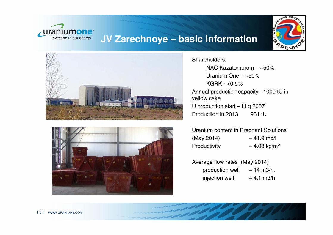
JV Zarechnoye – basic information
Shareholders:NAC Kazatomprom – ~50%Uranium One – ~50%KGRK - <0.5%
Annual production capacity - 1000 tU in yellow cake U production start – III q 2007Production in 2013 931 tU
Uranium content in Pregnant Solutions(May 2014) – 41.9 mg/lProductivity – 4.08 kg/m2
Average flow rates (May 2014)production well – 14 m3/h, injection well – 4.1 m3/h

| 4 | WWW.URANIUM1.COM 2
Zarechnoye deposit Mineralization outline
• Zarechnoye deposit relates to the sandstone hosted uranium deposit, and genetically associated with regional redox front zones.
• Uranium resources as of 24.06.2004 (State Contract) within the categories:В - 731 тС1 - 13,691 тС2 - 4,575 тTotal В+С1+С2 = 18,997 tU
• Total resources as of 01.01.2014 –14,373 tU
• Average uranium grade – 0.057%

| 5 | WWW.URANIUM1.COM
Regional geological cross section
Uranium mineralization is localized in permeable Upper Cretaceous sand sediments at a depth varying from 350 to 650 meters.

| 6 | WWW.URANIUM1.COM
Geological cross section of Zarechnoye
• Ore hosting environment is represented by permeable sand sediments (sands, gridstones, siltstones) interbedded with local water confining clay layers
• Permeable aquifers consist of sands and lenticular beds of siltstones and sandstones in various proportions.
• Uranium mineralization –Coffinite – 80%, Pitchblende – 20%
| 7 | WWW.URANIUM1.COM
Plugging in ISL
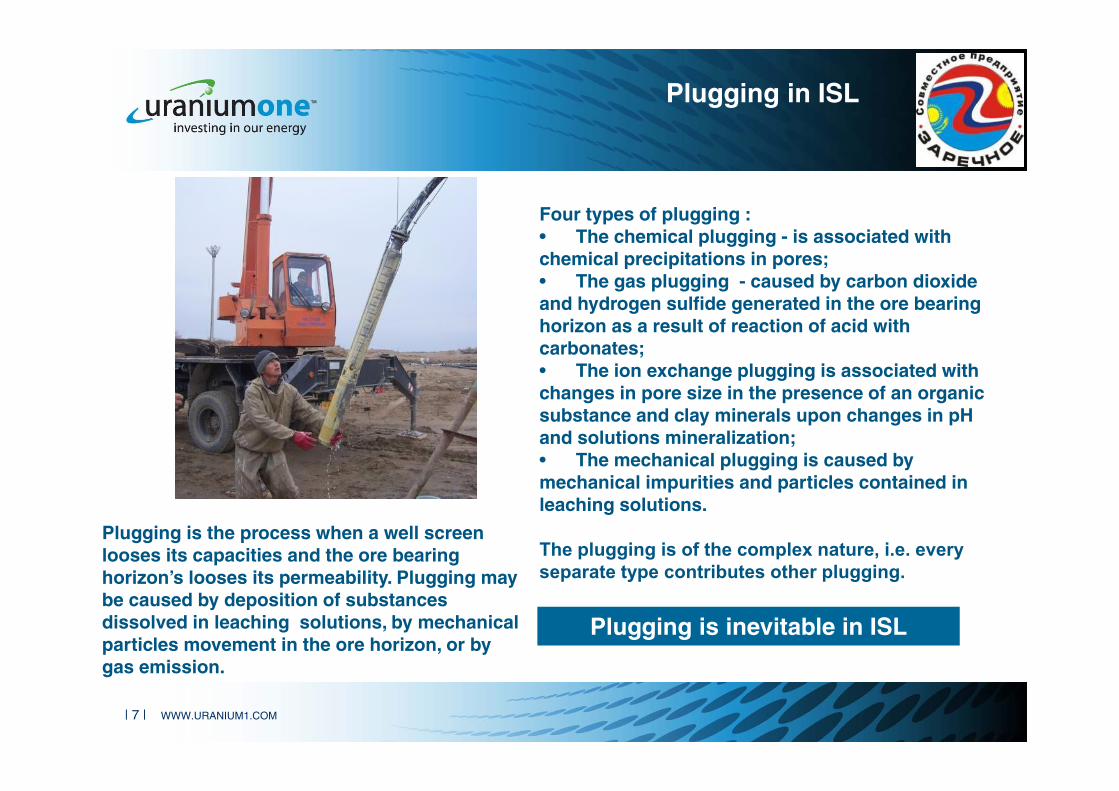
Plugging is the process when a well screen looses its capacities and the ore bearing horizon’s looses its permeability. Plugging may be caused by deposition of substances dissolved in leaching solutions, by mechanical particles movement in the ore horizon, or by gas emission.
Four types of plugging :• The chemical plugging - is associated with chemical precipitations in pores;• The gas plugging - caused by carbon dioxide and hydrogen sulfide generated in the ore bearing horizon as a result of reaction of acid with carbonates;• The ion exchange plugging is associated with changes in pore size in the presence of an organic substance and clay minerals upon changes in pH and solutions mineralization;• The mechanical plugging is caused by mechanical impurities and particles contained in leaching solutions.
The plugging is of the complex nature, i.e. every separate type contributes other plugging.
Plugging is inevitable in ISL
| 8 | WWW.URANIUM1.COM
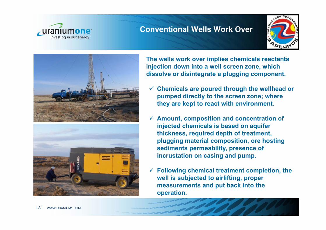
Conventional Wells Work Over
The wells work over implies chemicals reactants injection down into a well screen zone, which dissolve or disintegrate a plugging component.
Chemicals are poured through the wellhead or pumped directly to the screen zone; where they are kept to react with environment.
Amount, composition and concentration of injected chemicals is based on aquifer thickness, required depth of treatment, plugging material composition, ore hosting sediments permeability, presence of incrustation on casing and pump.
Following chemical treatment completion, the well is subjected to airlifting, proper measurements and put back into the operation.

| 9 | WWW.URANIUM1.COM
Basics of the New Wells Work Over Method
The aim is to find a chemical reagent that is capable to change balance of the system and to dissolveinsoluble in sulfuric acid compounds, or to convert plugging solids into easily soluble compounds.The proposed technology is based oil and gas industry experience in wells flow rate improvement.
Key reagents.Ammonium bifluoride (NH4HF2) ABF has been used as additive to sulfuric acid solution, and sulphonol (themixture of sodium salts of alkyl benzene sulfonic acids) as the surfactant for the plugging materialdisintegration.Ammonium bifluoride was selected due its ability for exchange reaction with sulfuric acid and generatehydrofluoric acid:
NH4HF2 + H2SO4 = NH4HSO4 + 2HF
The hydrofluoric acid which results from the reaction can easily interact with aluminum silicates and siliceouscompounds being part of both ore hosting and plugging sediments.
4HF+SiO2 = SiF4 + 2H2O
As a result, both plugging sediments and a part of the sands cement are dissolved, thus generally increasingeffective porosity of the ore bearing environment.The hydrofluoric acid is fully utilized due to large amount of quartz contained in sands.

| 10 | WWW.URANIUM1.COM
The New ABF Method – Main Test Stages
Conventional wells work over by airlifting
with mandatory registration of the
maximum flow rate value.
Treatment of a well by sulfuric acid solution
with ammonium bifluoride followed by the chemical reagent further pushing down into a screen zone by sulfuric acid solution
injecting (no ABF).
18 to 24 hours stand by
Airlifting with mandatory flow rate
measurement at pumping start and its
maximum value. Registration of
solution flow rate and its characteristics
(color, turbidity, foam presence, etc.).
Submersible pump installation and wells
restart, operation control and monitoring.

| 11 | WWW.URANIUM1.COM
At Work Performance Site
Wells Treating Portable Equipment Wells Washing Mobile Machine

| 12 | WWW.URANIUM1.COM
Treatment Start
Flow rate growth or drop, i.e. from 0.5 to 22m3/h (average 13.9m3/h), was recorded when injecting chemical reagent in wells at the initial stage.Solutions are muddy

| 13 | WWW.URANIUM1.COM
Mid of Treatment Stage
Then the flows go at higher rates but with pulsing intensity. Solutions are more transparent.

| 14 | WWW.URANIUM1.COM
Stable High Flow Rate – End of Works
At the final stage flow rate growth was observed when injecting solutions into the aquifer (8÷22 m3/h, average 17.4 m3/h).Flow rates of all treated wells have recovered back to the designed values (17.1 m3/h).

| 15 | WWW.URANIUM1.COM
Prior to ABF treatment After ABF treatment
№Well flow rate
before WWO, m3/hMax “historical” flow rate at beginning
of well operation, m3/hMax pumping flow rate after last
conventional WWO, m3/hAchieved pumping flow rate,
m3/h1 6-8 36 12 36-382 0-2 38 8 38-403 5 32 16-18 38-404 6-8 36 16-18 365 0-2 34 16 38-406 13 36 30 38-407 4 36 8 228 6 32 8 289 10 12 4 32
10 0 22 4 3011 0 36 12 4012 11 34 16 3613 5 36 5 4014 1 22 1 1815 7 34 14 3616 8 38 12 3417 10 36 20 3618 4 32 12 2619 7 34 16 38
Well data before and after ABF treatment

| 16 | WWW.URANIUM1.COM
Well flow rate variation before and after ABF treatment
Well 35-4-1Well flow rate variation before and after ABF treatment
Conventional well workover operations
ABF 24 May 2013
Conventional well workover operations
| 17 | WWW.URANIUM1.COM
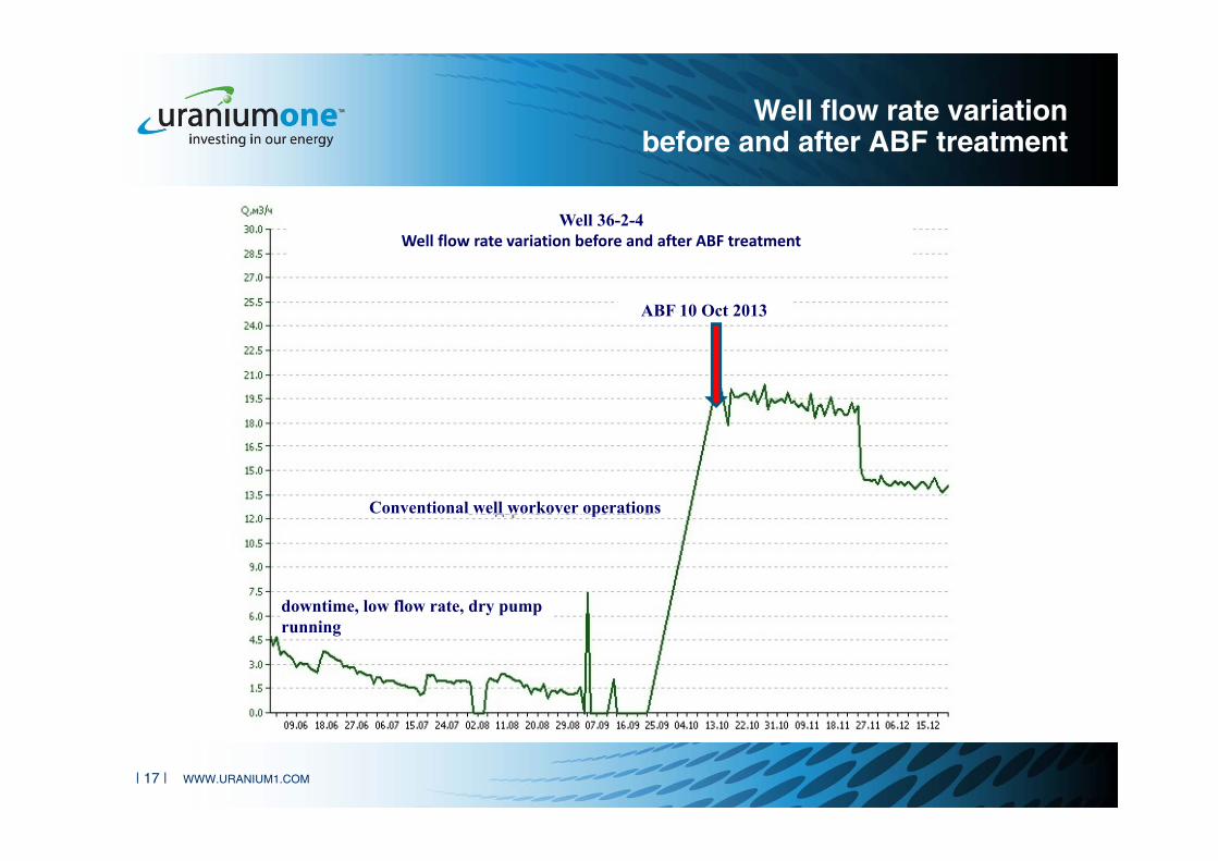
Well flow rate variation before and after ABF treatment
Well 36-2-4Well flow rate variation before and after ABF treatment
Conventional well workover operations
ABF 10 Oct 2013
downtime, low flow rate, dry pump running

| 18 | WWW.URANIUM1.COM
Main results
1. Over two dozen wells in eleven different well field blocks were treated during tests. Despite some differences in geological conditions, depths, screen design, plugging grade, the method showed a positive effect in all wells without exception.
2. Following the treatment all 19 most problematic wells were successfully put back into operation with their initial flow rates.
3. Chemical treatment of production wells resulted in the increase of their performance by 50% in average compared to their flow rate before the workover.
4. The flow rate of all treated wells was recovered back to the planned values matching the well performance at the beginning of operation (17.1 m3/h).
5. Preliminary economic calculations for Zarechnoye deposit show, that the cost of wells work over with ammonium bifluoride is 8-12% less than costs of the conventional wells work over.
6. The work over cycle timing being increased 2.5 - 3 times. 7. Following the regular solutions monitoring any changes in the of aquifer waters
and leaching solution composition were observed. That indicates method as environmentally friendly.

| 19 | WWW.URANIUM1.COM
Conclusions
1. The innovation method for wells flow rate recovery is based on the admixture of ammonium bifluoride.
2. This method has no alternatives for the “hard” wells recovery (which should be re-drilled), when conventional methods of chemical treatment and flow rate recovery do not produce significant results.
3. The method is applicable to all acid in-situ leaching.
4. Application of the method allows to increase the inter work over cycle by 2.5 – 3 times.
5. The developed method makes it possible to achieve maximum wells operational efficiency, reduce power costs for solutions pumping, optimise mining infrastructure.

| 20 | WWW.URANIUM1.COM
Thank you!
Alexander Boytsov,Ivan Avdassyov, Marat Niyetbayev,Mikhail Pershin,Artem N. Yermilov