
The multilayer advantage - KE KELIT€¦ · as sound insulation ... Kelox multilayer pipe l good...
33
1 The multilayer advantage MULTILAYER PIPE SYSTEM MULTILAYER PIPE SYSTEM
Transcript of The multilayer advantage - KE KELIT€¦ · as sound insulation ... Kelox multilayer pipe l good...

1
The multilayer advantage
m u l t i l a y e r p i p e s y s t e mm u l t i l a y e r p i p e s y s t e m
Index
Approval and registration 3Design of the pipes and quality assurance 4–5Insulated and un-insulated multilayer pipes 6–7Joining technology – press connection 8Joining technology – push connection 9Joining technology – screw connection 10 Compatibility of the screw fittings 11
Installation guidelines• Installation of the screw fitting 12–13• Installation of the press fitting 14–15• Development of the PROtec fitting 16• Installation of push fitting 17• 5 seconds to make a safe joint 18–19• Concealed manifold housing 20• Surface mounted manifold housing 21
Radiator heating• Types of heating systems – heat insulation – heating 22–23• Pipe sizing and pressure loss for heating systems 24• Pressure testing for heating systems 25
Drinking water installations• References to ÖNORM B 5019 26• Methods of installation for drinking water systems 27• Pipe sizing and pressure loss: EN806-3 28–29• Guidelines for pipe sizing: DIN 1988-3 30–31• Pipe sizing: DIN1988-3 32–33• Pipe sizing and pressure loss for hot/cold water systems 34• Heat insulation for hot/cold water systems 35 • Pressure testing for hot and cold water systems 36–37 • Heat expansion and force of expansion 38–40• Rinsing the piping and sound insulation 41Important installation guidelines 42–43• Product range 44–61 • Representative offices and headquarters 62–63
Please read the information contained in this handbook before you use KELOX ULTRAX for the first time, especially the information about how to make the joints.
2
m u l t i l a y e r p i p e s y s t e m
3
m u l t i l a y e r p i p e s y s t e m
Approval Registration
ÖVGW test registration
DVGW test registration
ÖNORM registration according to B 5157 and EN ISO 21003
No: 96345No: 97500
EU registered designAustrian trademarks 580 881
Certified Quality Assurance SystemÖNORM EN ISO 9001:2000
Reg. No. 366/0
KE KELIT s quality targets
1. Our quality targets are not confined to the product. They include all areas covered by ÖNORM EN ISO 9001:2000
2. Suppliers and customers are integrated into the quality assurance system to ensure that mistakes are prevented.
3. Every employee is responsible for the quality of his own work and should be highly motivated to continually assess his work.
4. Customer satisfaction can only be achieved by responding to the requirements of the customer and the market.
5. A responsible attitude to the environment can be achieved by manufacturing long- life products by environment-friendly processes.
Senator Karl Egger eh. Managing Director
4
m u l t i l a y e r p i p e s y s t e m
5
m u l t i l a y e r p i p e s y s t e m
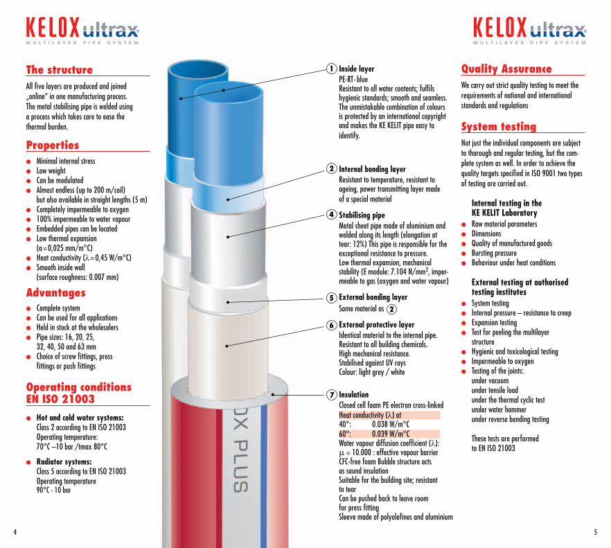
The structureAll five layers are produced and joined „online“ in one manufacturing process.The metal stabilising pipe is welded using a process which takes care to ease the thermal burden.
Properties l Minimal internal stressl Low weightl Can be modulated l Almost endless (up to 200 m/coil)
but also available in straight lengths (5 m) l Completely impermeable to oxygenl 100% impermeable to water vapourl Embedded pipes can be locatedl Low thermal expansion
(a = 0,025 mm/m°C)l Heat conductivity (λ= 0,45 W/m°C)l Smooth inside wall
(surface roughness: 0.007 mm)
Advantagesl Complete systeml Can be used for all applicationsl Held in stock at the wholesalersl Pipe sizes: 16, 20, 25,
32, 40, 50 and 63 mml Choice of screw fittings, press
fittings or push fittings
Operating conditions EN ISO 21003
l Hot and cold water systems:Class 2 according to EN ISO 21003 Operating temperature: 70°C –10 bar /tmax 80°C
l Radiator systems:Class 5 according to EN ISO 21003 Operating temperature 90°C - 10 bar
Inside layerPE-RT- blue Resistant to all water contents; fulfils hygienic standards; smooth and seamless. The unmistakable combination of colours is protected by an international copyright and makes the KE KELIT pipe easy to identify.
Internal bonding layerResistant to temperature, resistant to ageing, power transmitting layer made of a special material
Stabilising pipeMetal sheet pipe made of aluminium and welded along its length (elongation at tear: 12%) This pipe is responsible for the exceptional resistance to pressure.Low thermal expansion, mechanical stability (E module: 7.104 N/mm2, imper-meable to gas (oxygen and water vapour)
External bonding layerSame material as
External protective layerIdentical material to the internal pipe. Resistant to all building chemicals. High mechanical resistance. Stabilised against UV raysColour: light grey / white
InsulationClosed cell foam PE electron cross-linkedHeat conductivity (λ) at40°: 0.038 W/m°C60°: 0.039 W/m°CWater vapour diffusion coefficient (λ):μ = 10.000 : effective vapour barrierCFC-free foam Bubble structure acts as sound insulation Suitable for the building site; resistant to tearCan be pushed back to leave room for press fittingSleeve made of polyolefines and aluminium
1
2
4
5
6
7
Quality AssuranceWe carry out strict quality testing to meet the requirements of national and international standards and regulations
System testingNot just the individual components are subject to thorough and regular testing, but the com-plete system as well. In order to achieve the quality targets specified in ISO 9001 two types of testing are carried out.
Internal testing in the KE KELIT Laboratory
l Raw material parametersl Dimensionsl Quality of manufactured goodsl Bursting pressurel Behaviour under heat conditions
External testing at authorised testing institutes
l System testingl Internal pressure – resistance to creepl Expansion testingl Test for peeling the multilayer
structurel Hygienic and toxicological testingl Impermeable to oxygenl Testing of the joints:
under vacuum under tensile load under the thermal cyclic test under water hammer under reverse bending testing These tests are performed to EN ISO 21003
2
6
m u l t i l a y e r p i p e s y s t e m
7
m u l t i l a y e r p i p e s y s t e m
Heat emission from the floor in Watt/m at 20°C room temperature
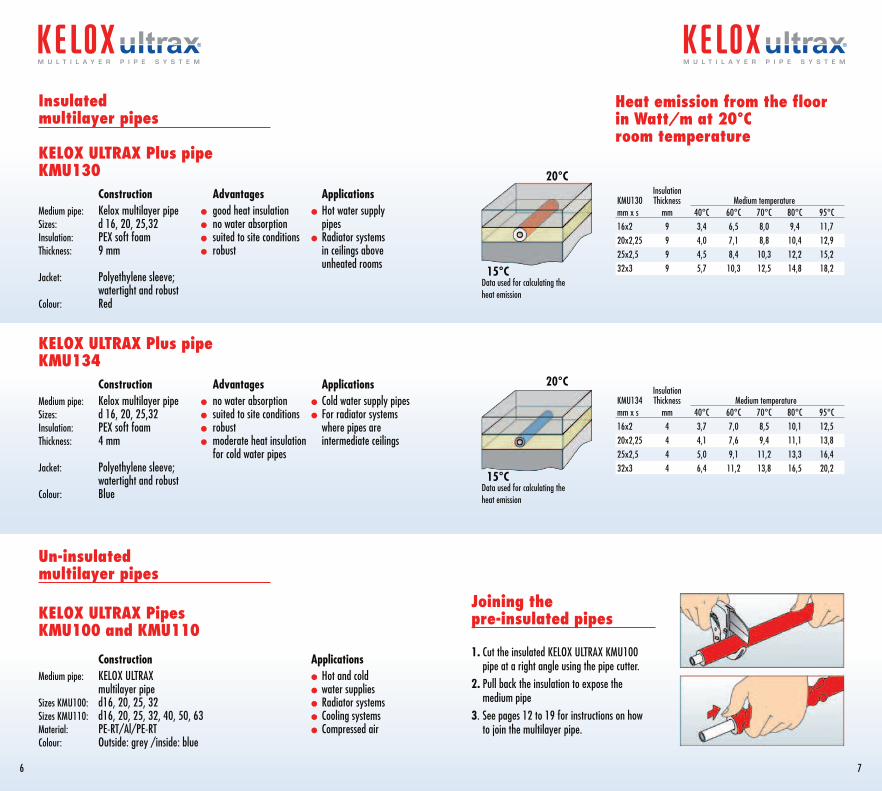
Insulation KMU134 Thickness Medium temperatur e mm x s mm 40°C 60°C 70°C 80°C 95°C16x2 4 3,7 7,0 8,5 10,1 12,520x2,25 4 4,1 7,6 9,4 11,1 13,825x2,5 4 5,0 9,1 11,2 13,3 16,432x3 4 6,4 11,2 13,8 16,5 20,2
Joining the pre-insulated pipes 1. Cut the insulated KELOX ULTRAX KMU100
pipe at a right angle using the pipe cutter.2. Pull back the insulation to expose the
medium pipe3. See pages 12 to 19 for instructions on how
to join the multilayer pipe.
Data used for calculating the heat emission
20°C
15°C
Data used for calculating the heat emission
20°C
15°C
Insulated multilayer pipes
KELOX ULTRAX Plus pipe KMU130 Construction Advantages ApplicationsMedium pipe: Kelox multilayer pipe l good heat insulation l Hot water supplySizes: d 16, 20, 25,32 l no water absorption pipesInsulation: PEX soft foam l suited to site conditions l Radiator systemsThickness: 9 mm l robust in ceilings above unheated roomsJacket: Polyethylene sleeve; watertight and robustColour: Red
KELOX ULTRAX Plus pipe KMU134 Construction Advantages ApplicationsMedium pipe: Kelox multilayer pipe l no water absorption l Cold water supply pipesSizes: d 16, 20, 25,32 l suited to site conditions l For radiator systems Insulation: PEX soft foam l robust where pipes areThickness: 4 mm l moderate heat insulation intermediate ceilings for cold water pipesJacket: Polyethylene sleeve; watertight and robustColour: Blue
Un-insulated multilayer pipes
KELOX ULTRAX Pipes KMU100 and KMU110
Construction ApplicationsMedium pipe: KELOX ULTRAX l Hot and cold multilayer pipe l water suppliesSizes KMU100: d16, 20, 25, 32 l Radiator systemsSizes KMU110: d16, 20, 25, 32, 40, 50, 63 l Cooling systemsMaterial: PE-RT/Al/PE-RT l Compressed airColour: Outside: grey /inside: blue
InsulationKMU130 Thickness Medium temperature mm x s mm 40°C 60°C 70°C 80°C 95°C16x2 9 3,4 6,5 8,0 9,4 11,720x2,25 9 4,0 7,1 8,8 10,4 12,925x2,5 9 4,5 8,4 10,3 12,2 15,232x3 9 5,7 10,3 12,5 14,8 18,2
32 4 51
The joint technology
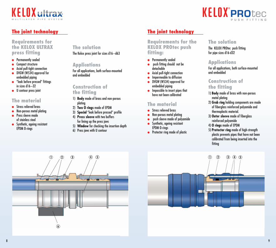
Requirements for the KELOX PROtec push fitting:l Permanently sealedl push fitting should not be
detachablel Axial pull-tight connection l Impermeable to diffusionl DVGW (W534) approval for
embedded piping l Impossible to insert pipes that
have not been calibrated
The materiall Stress relieved brassl Non-porous metal plating l push sleeve made of polyamidel Synthetic, ageing resistant
EPDM O-ringsl Protector ring made of plastic
The solutionThe KELOX PROtec push fitting for pipe sizes d16-d32
ApplicationsFor all applications, both surface-mounted and embedded
Construction of the fitting1) Body made of brass with non-porous
metal plating 2) Grab ring holding components are made
of fiberglass reinforced polyamide and thermoplastic material.
3) Outer sleeve made of fiberglass reinforced polyamide
4) O rings made of EPDM5) Protector ring made of high-strength
plastic prevents pipes that have not been calibrated from being inserted into the fitting
8
m u l t i l a y e r p i p e s y s t e m
9
The solutionThe Kelox press joint for sizes d16 –d63
ApplicationsFor all applications, both surface-mounted and embedded
Construction of the fitting1) Body made of brass and non-porous
plating2) Two O rings made of EPDM3) Special “leak before pressed” profile4) Press sleeve with two buffers
for lining up the press jaws 5) Window for checking the insertion depth6) Press jaws with U contour
The joint technology
Requirements for the KELOX ULTRAX press fittingl Permanently sealedl Compact structurel Axial pull-tight connection l DVGW (W534) approval for
embedded pipingl “leak before pressed“ fittings
in sizes d16 –32l U contour press joint
The materiall Stress relieved brassl Non-porous metal plating l Press sleeve made
of stainless steell Synthetic, ageing resistant
EPDM O-rings
1 2 3 4 5
6
PRO tecp u s h f i t t i n g
Dim: d16–25
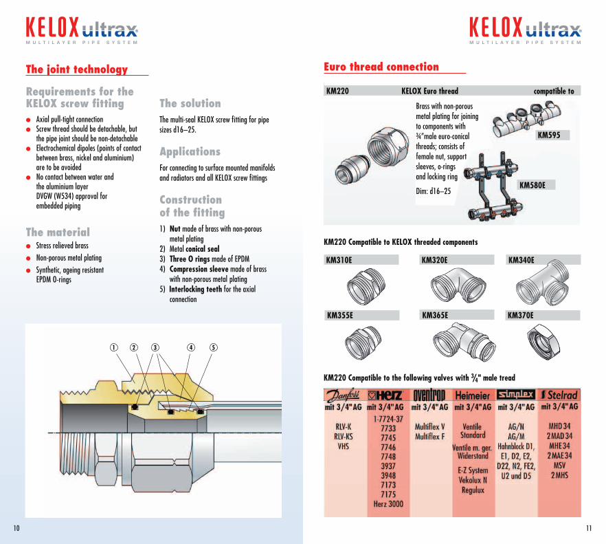
KM220 Compatible to the following valves with 3/4" male tread
KM220 Compatible to KELOX threaded components
Euro thread connection
KM220 KELOX Euro thread compatible to
The joint technology
Requirements for the KELOX screw fitting l Axial pull-tight connection l Screw thread should be detachable, but
the pipe joint should be non-detachablel Electrochemical dipoles (points of contact
between brass, nickel and aluminium) are to be avoided
l No contact between water and the aluminium layer DVGW (W534) approval for embedded piping
The materiall Stress relieved brassl Non-porous metal plating l Synthetic, ageing resistant
EPDM O-rings
The solutionThe multi-seal KELOX screw fitting for pipe sizes d16–25.
ApplicationsFor connecting to surface mounted manifolds and radiators and all KELOX screw fittings
Construction of the fitting1) Nut made of brass with non-porous
metal plating2) Metal conical seal3) Three O rings made of EPDM4) Compression sleeve made of brass
with non-porous metal plating5) Interlocking teeth for the axial
connection
10
m u l t i l a y e r p i p e s y s t e m
11
m u l t i l a y e r p i p e s y s t e m
KM310E KM320E
KM355E KM370E
KM580E
KM340E
KM595
KM365E
1 53 42
Brass with non-porous metal plating for joining to components with ¾”male euro-conical threads; consists of female nut, support sleeves, o-rings and locking ring
Dim: d16–25
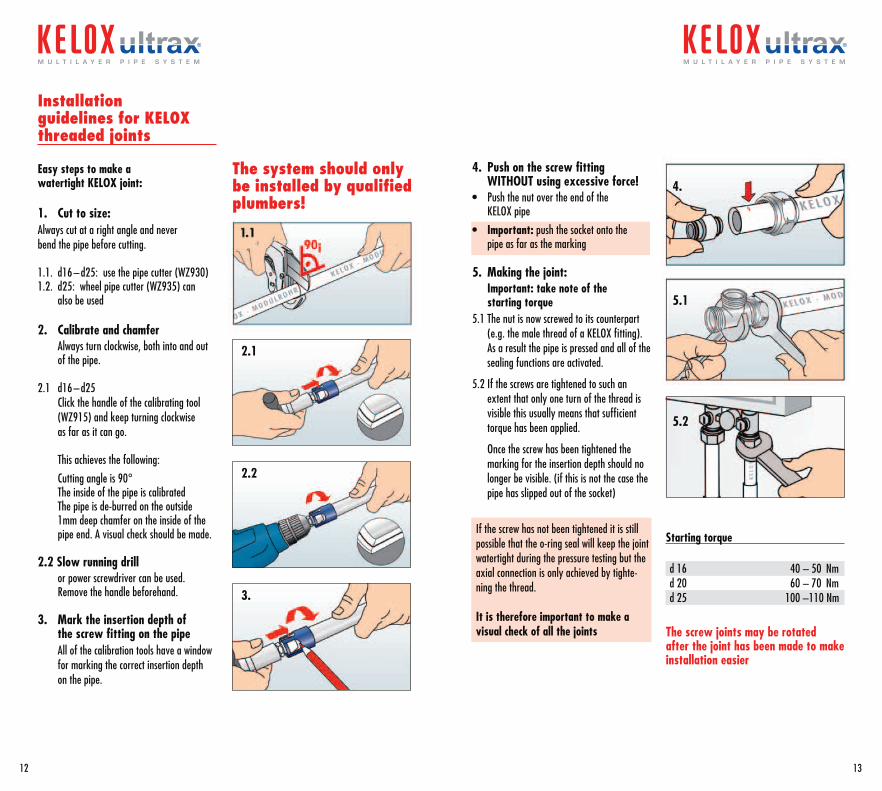
Installation guidelines for KELOX threaded joints Easy steps to make a watertight KELOX joint:
1. Cut to size: Always cut at a right angle and never bend the pipe before cutting.
1.1. d16 – d25: use the pipe cutter (WZ930)1.2. d25: wheel pipe cutter (WZ935) can
also be used
2. Calibrate and chamfer Always turn clockwise, both into and out
of the pipe.
2.1 d16 – d25 Click the handle of the calibrating tool (WZ915) and keep turning clockwise as far as it can go.
This achieves the following:
Cutting angle is 90° The inside of the pipe is calibrated The pipe is de-burred on the outside 1mm deep chamfer on the inside of the
pipe end. A visual check should be made.
2.2 Slow running drill or power screwdriver can be used.
Remove the handle beforehand.
3. Mark the insertion depth of the screw fitting on the pipe
All of the calibration tools have a window for marking the correct insertion depth on the pipe.
The screw joints may be rotated after the joint has been made to make installation easier
Starting torque
d 16 40 – 50 Nmd 20 60 – 70 Nmd 25 100 –110 Nm
The system should only be installed by qualified plumbers!
2.1
2.2
4.
5.1
5.2
3.
12
m u l t i l a y e r p i p e s y s t e m
13
m u l t i l a y e r p i p e s y s t e m
4. Push on the screw fitting WITHOUT using excessive force!
• Push the nut over the end of the KELOX pipe
• Important: push the socket onto the pipe as far as the marking
5. Making the joint: Important: take note of the starting torque5.1 The nut is now screwed to its counterpart
(e.g. the male thread of a KELOX fitting). As a result the pipe is pressed and all of the sealing functions are activated.
5.2 If the screws are tightened to such an extent that only one turn of the thread is visible this usually means that sufficient torque has been applied.
Once the screw has been tightened the marking for the insertion depth should no longer be visible. (if this is not the case the pipe has slipped out of the socket)
If the screw has not been tightened it is still possible that the o-ring seal will keep the joint watertight during the pressure testing but the axial connection is only achieved by tighte-ning the thread.
It is therefore important to make a visual check of all the joints
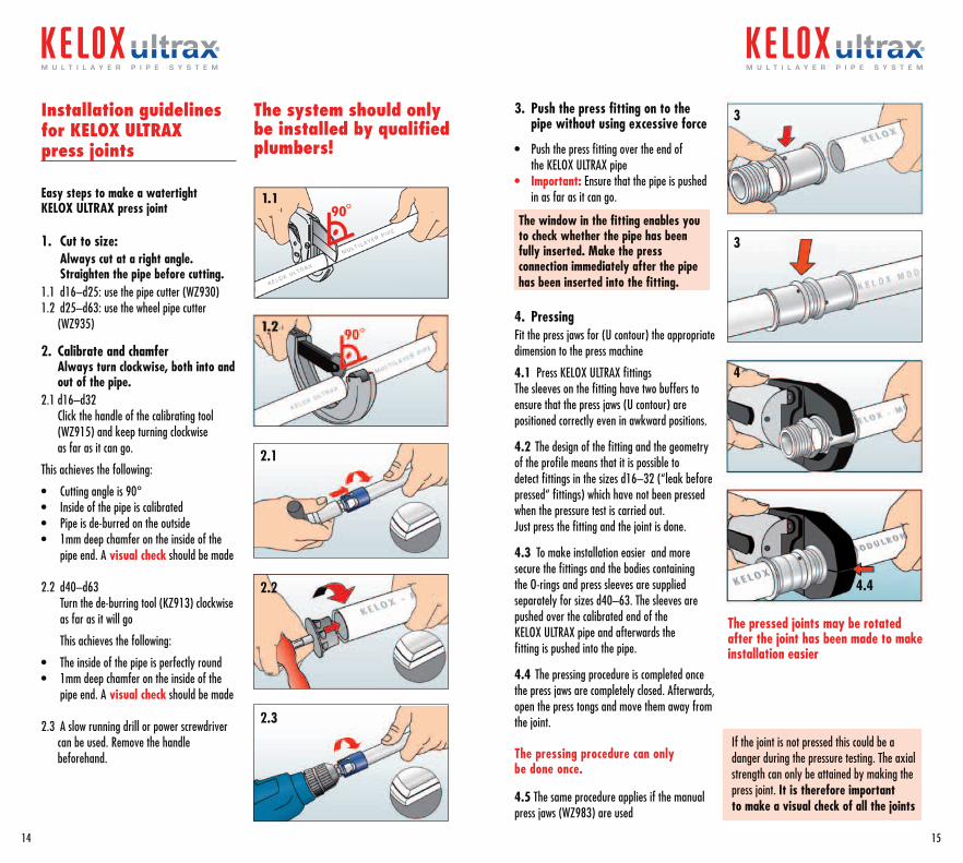
Installation guidelines for KELOX ULTRAX press joints
Easy steps to make a watertight KELOX ULTRAX press joint
1. Cut to size: Always cut at a right angle.
Straighten the pipe before cutting.1.1 d16–d25: use the pipe cutter (WZ930)1.2 d25–d63: use the wheel pipe cutter
(WZ935)
2. Calibrate and chamfer Always turn clockwise, both into and out of the pipe.
2.1 d16–d32 Click the handle of the calibrating tool
(WZ915) and keep turning clockwise as far as it can go.
This achieves the following:
• Cutting angle is 90°• Inside of the pipe is calibrated• Pipe is de-burred on the outside• 1mm deep chamfer on the inside of the
pipe end. A visual check should be made
2.2 d40–d63 Turn the de-burring tool (KZ913) clockwise as far as it will go
This achieves the following:
• The inside of the pipe is perfectly round• 1mm deep chamfer on the inside of the
pipe end. A visual check should be made
2.3 A slow running drill or power screwdriver can be used. Remove the handle beforehand.
3. Push the press fitting on to the pipe without using excessive force
• Push the press fitting over the end of the KELOX ULTRAX pipe
• Important: Ensure that the pipe is pushed in as far as it can go.
The window in the fitting enables you to check whether the pipe has been fully inserted. Make the press connection immediately after the pipe has been inserted into the fitting.
4. PressingFit the press jaws for (U contour) the appropriate dimension to the press machine
4.1 Press KELOX ULTRAX fittingsThe sleeves on the fitting have two buffers to ensure that the press jaws (U contour) are positioned correctly even in awkward positions.
4.2 The design of the fitting and the geometry of the profile means that it is possible to detect fittings in the sizes d16–32 (“leak before pressed“ fittings) which have not been pressed when the pressure test is carried out.Just press the fitting and the joint is done.
4.3 To make installation easier and more secure the fittings and the bodies containing the O-rings and press sleeves are supplied separately for sizes d40–63. The sleeves are pushed over the calibrated end of the KELOX ULTRAX pipe and afterwards the fitting is pushed into the pipe.
4.4 The pressing procedure is completed once the press jaws are completely closed. Afterwards, open the press tongs and move them away from the joint.
The pressing procedure can only be done once.
4.5 The same procedure applies if the manual press jaws (WZ983) are used
The pressed joints may be rotated after the joint has been made to make installation easier
The system should only be installed by qualified plumbers!
2.1
2.2
2.3
3
3
4
4.4
If the joint is not pressed this could be a danger during the pressure testing. The axial strength can only be attained by making the press joint. It is therefore important to make a visual check of all the joints
14
m u l t i l a y e r p i p e s y s t e m
15
m u l t i l a y e r p i p e s y s t e m
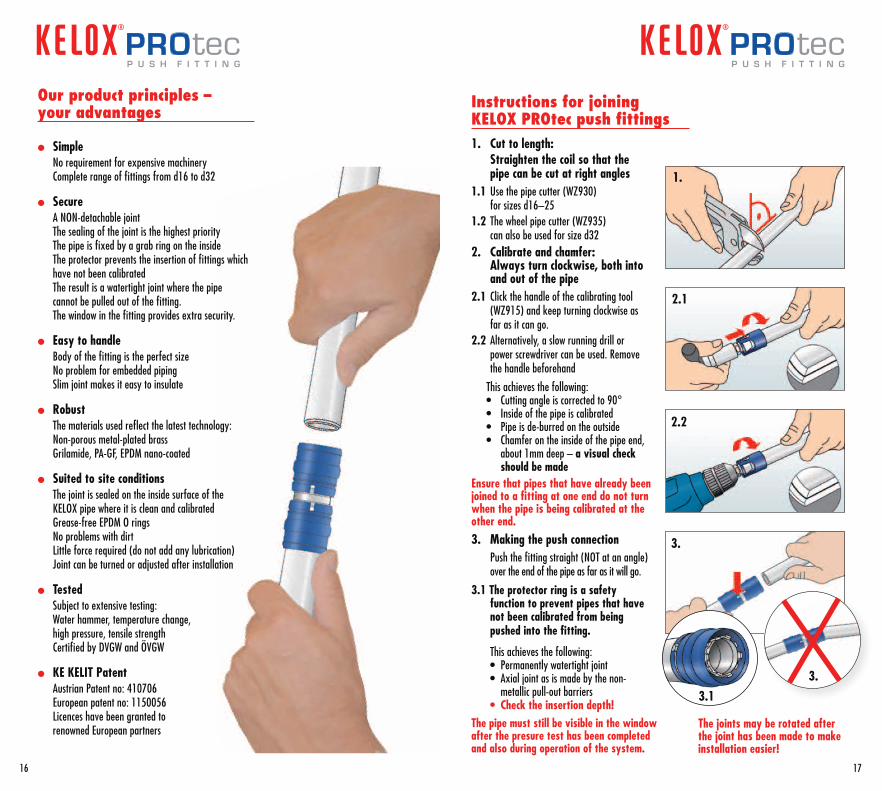
Our product principles – your advantages
l Simple No requirement for expensive machinery Complete range of fittings from d16 to d32
l Secure A NON-detachable joint The sealing of the joint is the highest priority The pipe is fixed by a grab ring on the inside The protector prevents the insertion of fittings which
have not been calibrated The result is a watertight joint where the pipe
cannot be pulled out of the fitting. The window in the fitting provides extra security.
l Easy to handle Body of the fitting is the perfect size No problem for embedded piping Slim joint makes it easy to insulate
l Robust The materials used reflect the latest technology: Non-porous metal-plated brass Grilamide, PA-GF, EPDM nano-coated
l Suited to site conditions The joint is sealed on the inside surface of the
KELOX pipe where it is clean and calibrated Grease-free EPDM O rings No problems with dirt Little force required (do not add any lubrication) Joint can be turned or adjusted after installation
l Tested Subject to extensive testing: Water hammer, temperature change,
high pressure, tensile strength Certified by DVGW and ÖVGW
l KE KELIT Patent Austrian Patent no: 410706 European patent no: 1150056 Licences have been granted to
renowned European partners
1. Cut to length: Straighten the coil so that the
pipe can be cut at right angles1.1 Use the pipe cutter (WZ930)
for sizes d16–251.2 The wheel pipe cutter (WZ935)
can also be used for size d32 2. Calibrate and chamfer:
Always turn clockwise, both into and out of the pipe
2.1 Click the handle of the calibrating tool (WZ915) and keep turning clockwise as far as it can go.
2.2 Alternatively, a slow running drill or power screwdriver can be used. Remove the handle beforehand
This achieves the following: • Cutting angle is corrected to 90° • Inside of the pipe is calibrated • Pipe is de-burred on the outside • Chamfer on the inside of the pipe end,
about 1mm deep – a visual check should be made
Ensure that pipes that have already been joined to a fitting at one end do not turn when the pipe is being calibrated at the other end.3. Making the push connection Push the fitting straight (NOT at an angle)
over the end of the pipe as far as it will go.
3.1 The protector ring is a safety function to prevent pipes that have not been calibrated from being pushed into the fitting.
This achieves the following: • Permanently watertight joint • Axial joint as is made by the non-
metallic pull-out barriers • Check the insertion depth!The pipe must still be visible in the window after the presure test has been completed and also during operation of the system.
The joints may be rotated after the joint has been made to make installation easier!
1.
2.1
2.2
3.
3.13.
Instructions for joining KELOX PROtec push fittings
16 17
PRO tecp u s h f i t t i n g
PRO tecp u s h f i t t i n g
Points to observe when working with KELOX
1. By following the guidelines carefully KELOX joints are very secure and pose no problems
2. It is essential that the system is installed by a qualified professional.
3. Mistakes made in installation or non-observance of the guidelines (pages 12–19, 42 and 43) cannot be compensated by pressure testing.
4. The recommended pressure tests (pages 25 and 37) are no gua-rantee against mistakes made during installation
5. Every pressure test is just a reflection of the current status of a section of the system.
6. The long-term properties are documented in the appropriate standards and are monitored by authorised institutes.
7. The quality of the final instal-lation is dependent to a high degree on the care YOU take.
Spend 5 seconds checking each joint for your security
3 seconds Visual check of the pipe end
to ensure that the whole of the circumference has been chamfered
This ensures that:l the pipe has been correctly
calibratedl The O-rings cannot be displaced
or damaged.l Pipes can be joined without
excessive force
2 seconds Check the insertion depth
This ensures:l The axial joint is made when
the joint is screwed or pressed.l The grab ring in the push
fittings is activated and secures the axial joint.
0 seconds (Where possible) don’t waste
any time between inserting the pipe and making the press or screw joint
This ensures that:l The press has not been
forgottenl The joining of the screw fitting
has not been forgottenl Full insertion of the pipe is
required for the push fitting to function
Visual check of the fitting
Window on the press coupling
Marking on the pipe for the screw fitting
Grooves are visible on the fittings
Number of visible turns on the thread kept to a minimum
18
m u l t i l a y e r p i p e s y s t e m
19
m u l t i l a y e r p i p e s y s t e m
Installation guidelines
KELOX concealed manifold housingKM 570 KELOX main frame for the manifold housing KM 571 Visible components for the manifold housing (these parts are packaged separately)
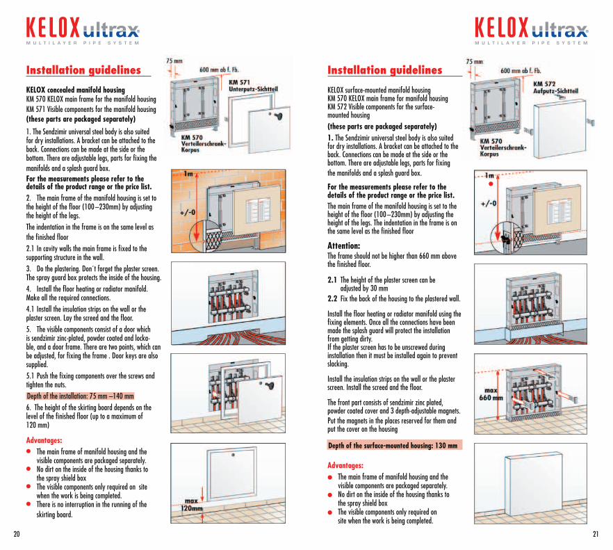
1. The Sendzimir universal steel body is also suited for dry installations. A bracket can be attached to the back. Connections can be made at the side or the bottom. There are adjustable legs, parts for fixing the manifolds and a splash guard box.For the measurements please refer to the details of the product range or the price list. 2. The main frame of the manifold housing is set to the height of the floor (100 –230mm) by adjusting the height of the legs.The indentation in the frame is on the same level as the finished floor 2.1 In cavity walls the main frame is fixed to the supporting structure in the wall.3. Do the plastering. Don´t forget the plaster screen. The spray guard box protects the inside of the housing.4. Install the floor heating or radiator manifold. Make all the required connections.4.1 Install the insulation strips on the wall or the plaster screen. Lay the screed and the floor.5. The visible components consist of a door which is sendzimir zinc-plated, powder coated and locka-ble, and a door frame. There are two points, which can be adjusted, for fixing the frame . Door keys are also supplied.5.1 Push the fixing components over the screws and tighten the nuts.Depth of the installation: 75 mm –140 mm6. The height of the skirting board depends on the level of the finished floor (up to a maximum of 120 mm)
Advantages:• The main frame of manifold housing and the
visible components are packaged separately.• No dirt on the inside of the housing thanks to
the spray shield box• The visible components only required on site
when the work is being completed.• There is no interruption in the running of the
skirting board.
Installation guidelines
KELOX surface-mounted manifold housing KM 570 KELOX main frame for manifold housing KM 572 Visible components for the surface- mounted housing (these parts are packaged separately)1. The Sendzimir universal steel body is also suited for dry installations. A bracket can be attached to the back. Connections can be made at the side or the bottom. There are adjustable legs, parts for fixing the manifolds and a splash guard box.
For the measurements please refer to the details of the product range or the price list. The main frame of the manifold housing is set to the height of the floor (100 –230mm) by adjusting the height of the legs. The indentation in the frame is on the same level as the finished floor
Attention:The frame should not be higher than 660 mm above the finished floor.
2.1 The height of the plaster screen can be adjusted by 30 mm2.2 Fix the back of the housing to the plastered wall.
Install the floor heating or radiator manifold using the fixing elements. Once all the connections have been made the splash guard will protect the installation from getting dirty.If the plaster screen has to be unscrewed during installation then it must be installed again to prevent slacking.
Install the insulation strips on the wall or the plaster screen. Install the screed and the floor.
The front part consists of sendzimir zinc plated, powder coated cover and 3 depth-adjustable magnets.Put the magnets in the places reserved for them and put the cover on the housing
Depth of the surface-mounted housing: 130 mm
Advantages:l The main frame of manifold housing and the
visible components are packaged separately.l No dirt on the inside of the housing thanks to
the spray shield boxl The visible components only required on
site when the work is being completed.
l
20
m u l t i l a y e r p i p e s y s t e m
21
m u l t i l a y e r p i p e s y s t e m
The classic two pipe system
Design criteria for an efficient system
Taking into account the total length of the piping and the extra losses at the system com-ponents (e.g. valves) the pressure loss can be assumed to be 100 –200 Pa/m
The standard optiontried and trusted
Advantagesl Same temperature for all of the radiators
(source of comfort)l Recognised system for calculating heat costsl Typical system for renovation of old
buildingsl Well suited for skirting boards
The one pipe system
Design criteria for an efficient system
Taking into account the total length of the main riser in one pipe systems and the extra losses at the system components (pipes branching off from the riser, Z values of 4 way valves …) the pressure loss can be assumed to be 100 –200 Pa/m
The “savings option”Quick and value for money
AdvantagesUsing 4-way valvesl No connections in the floorl Very quick installationl Only one pipe size after the riser
Heat insulation for heating pipes
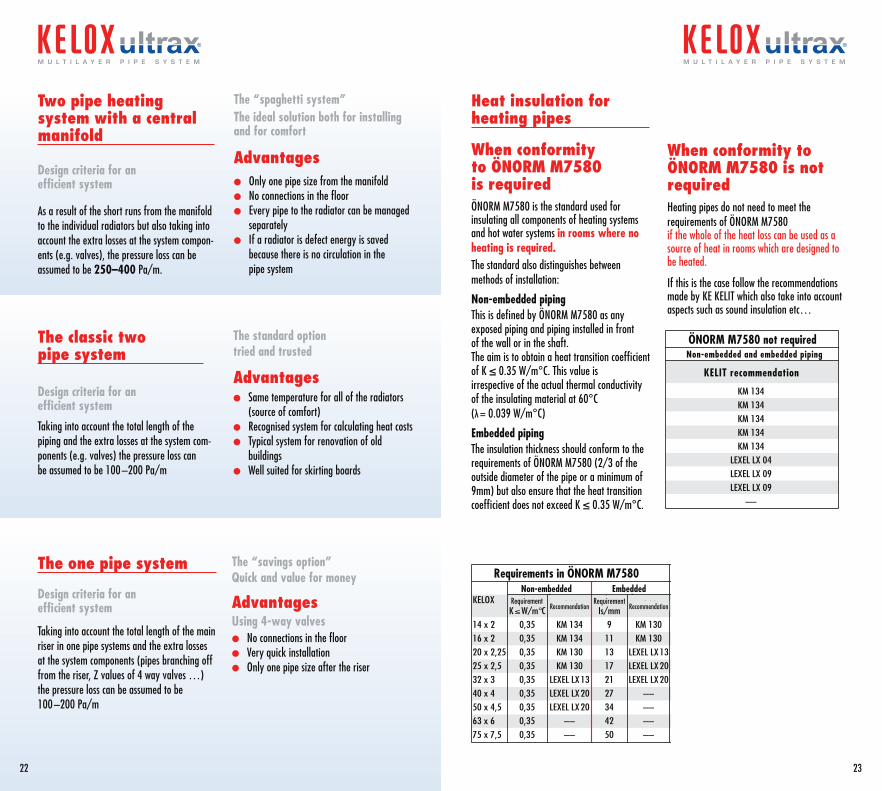
When conformity to ÖNORM M7580 is requiredÖNORM M7580 is the standard used for insulating all components of heating systems and hot water systems in rooms where no heating is required.The standard also distinguishes between methods of installation:
Non-embedded pipingThis is defined by ÖNORM M7580 as any exposed piping and piping installed in front of the wall or in the shaft. The aim is to obtain a heat transition coefficient of K ≤ 0.35 W/m°C. This value is irrespective of the actual thermal conductivity of the insulating material at 60°C (λ = 0.039 W/m°C)
Embedded pipingThe insulation thickness should conform to the requirements of ÖNORM M7580 (2/3 of the outside diameter of the pipe or a minimum of 9mm) but also ensure that the heat transition coefficient does not exceed K ≤ 0.35 W/m°C.
When conformity to ÖNORM M7580 is not requiredHeating pipes do not need to meet the requirements of ÖNORM M7580 if the whole of the heat loss can be used as a source of heat in rooms which are designed to be heated.
If this is the case follow the recommendations made by KE KELIT which also take into account aspects such as sound insulation etc…
Oberputz UnterputzKELOX Forderung Empfehlung Forderung Empfehlung
K≤W/m°C Is/mm14 x 2 0,35 KM 134 9 KM 13016 x 2 0,35 KM 134 11 KM 13020 x 2,25 0,35 KM 130 13 LEXEL LX1325 x 2,5 0,35 KM 130 17 LEXEL LX2032 x 3 0,35 LEXEL LX13 21 LEXEL LX2040 x 4 0,35 LEXEL LX20 27 ––50 x 4,5 0,35 LEXEL LX20 34 ––63 x 6 0,35 –– 42 ––75 x 7,5 0,35 –– 50 ––
Oberputz- und Unterputz
KELIT Empfehlung
KM 134KM 134KM 134KM 134
LEXEL LX 04LEXEL LX 04LEXEL LX 09LEXEL LX 09
––
Oberputz- und Unterputz
KELIT Empfehlung
KM 134KM 134KM 134KM 134KM 134
LEXEL LX 04LEXEL LX 09LEXEL LX 09
––
22
m u l t i l a y e r p i p e s y s t e m
23
m u l t i l a y e r p i p e s y s t e m
Two pipe heating system with a central manifold
Design criteria for an efficient system
As a result of the short runs from the manifold to the individual radiators but also taking into account the extra losses at the system compon-ents (e.g. valves), the pressure loss can be assumed to be 250–400 Pa/m.
The “spaghetti system” The ideal solution both for installing and for comfort
Advantagesl Only one pipe size from the manifoldl No connections in the floorl Every pipe to the radiator can be managed
separatelyl If a radiator is defect energy is saved
because there is no circulation in the pipe system
Requirements in ÖNORM M7580
KELIT recommendation
Non-embedded and embedded pipingÖNORM M7580 not required
Non-embeddedRequirement
Recommendation RecommendationRequirement
Embedded
Pressure testing report for heating systemsKE KELIT recommends carrying out the pressure testing according to the guidelines in DIN18380Please note that a pressure test is an assessment of how the system is functioning at the time of the test. It is not a guarantee against any mistakes made during installation.Check all the points concerning the installation of the system (pages 12 –19) before starting the pressure test.
Pressure testThe test pressure is equal to 1.3 times the operating pressure or a minimum of 1 bar above the operating temperature at every point. Only manometers which can read a change of pressure of 0.1 bar should be used. The manometer should be located at the lowest possible point in the system.
Time should be allocated to allow for the equalisation of the temperature between the ambient temperature and the medium temperature after the test pressure has been set. When this period has elapsed the test pressure should be re-set.
All tanks, components and faucets which are unsuited to pressure testing should be separated from the system during the pressure testing. The system is then filled with filtered water and the air removed. During the testing a visual check should be made at all the joints.
The testing pressure must be maintained for 2 hours and should not drop more than 0.2 bar. There should be no leaking at the joints during the test.
Testing pressure: ……. bar
Testing time: ……. hours
The pressure did not fall by ≥ 0.2 during testing
The system contains ……….. . . . . . . . . . . . .…………….. antifreeze
The system contains no antifreeze and was completely emptied for safety reasons.
Location: . . . . . . . . . . . . . . . . . . . . . . . . . . . . . . . . . . . . . . . . . . . . . . . . . . . . . . . . . . . . . . . . . . . . . . . . . . . . . . . . . . . . . . . . . . . . . . . . . . . . . .
Building: . . . . . . . . . . . . . . . . . . . . . . . . . . . . . . . . . . . . . . . . . . . . . . . . . . . . . . . . . . . . . . . . . . . . . . . . . . . . . . . . . . . . . . . . . . . . . . . . . . . . . .
System pressure: . . . . . . . . . . . . . . . . . . . . . . . . . . . . . . . . . . . . . . . . . . . . . . . . . . . . . . . . . . . . . . . . . . . . . . . . . . . . . . . . . . . . . . . . . . . . . .
Confirmation
Person in charge: . . . . . . . . . . . . . . . . . . . . . . . . . . . . . . . . . . . . . . . . . . . . . . . . . . . . . . . . . . . . . . . . . . . . . . . . . . . . . . . . . . . . . . . . . . . . .
Date: . . . . . . . . . . . . . . . . . . . . . . Time from: . . . . . . . . . . . . . . . . . . . . . . . . . . . . . . . to: . . . . . . . . . . . . . . . . . . . . . . . . . . . . . . .
Contractor . . . . . . . . . . . . . . . . . . . . . . . . . . . . . . . . . . . . . . . . . . . . . . . . . . . . . . . . . . . . . . . . . . . . . . . . . . . . . . . . . . . . . . . . . . . . . . . . . . . . . signature/stamp900600 700 800
0,2
0,3
0,40,5
0,60,75
1,0
1,5
2,02,5
3,0
15
1500
d75x7,5
d16x2
d20x2,25
d25x2,5
d32x3
d40x4
d50x4,5d63x6
2,5
2,0
Pressure loss
Wat
er f
low
Lit
re /
h
Flow velocity: m/sec
20
6000
7000
8000
9000
500
2
4
1
1,5
3
9000800070006000
5000
4000
3000
2000
1000900800700600
500
400
300
200
10090807060
50
40
30
30.000
20.000
10.000
40.000
150
1500
15.000
PA/m
mm/WS
Output in kW at:
4000
3000
20
40
60
80
100
150
200
300
400
500
6
8
10
15
30
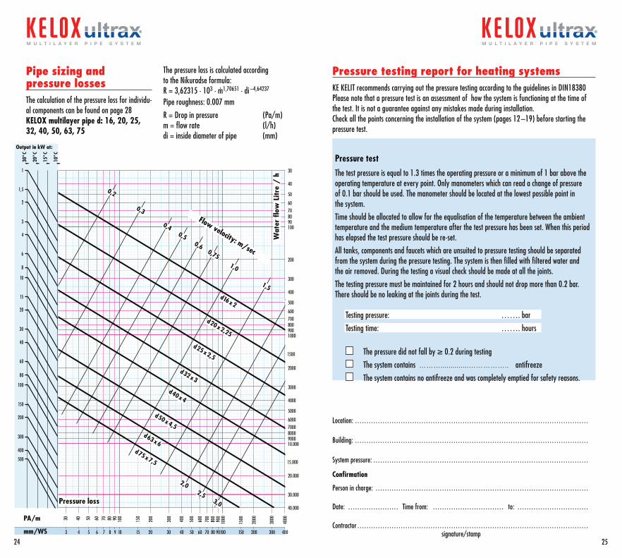
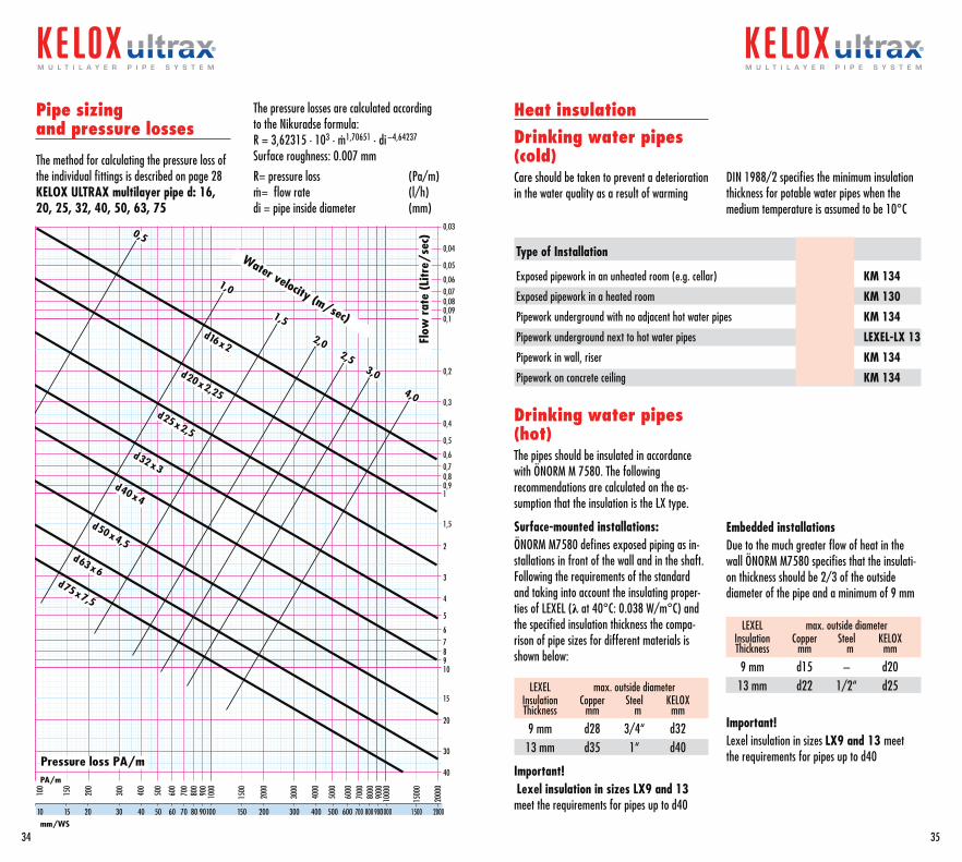
Pipe sizing and pressure lossesThe calculation of the pressure loss for individu-al components can be found on page 28KELOX multilayer pipe d: 16, 20, 25, 32, 40, 50, 63, 75
The pressure loss is calculated according to the Nikuradse formula:R = 3,62315 · 103 · m· 1,70651 · di –4,64237
Pipe roughness: 0.007 mm
R = Drop in pressure (Pa/m)m = flow rate (l/h)di = inside diameter of pipe (mm)
24
m u l t i l a y e r p i p e s y s t e m
25
m u l t i l a y e r p i p e s y s t e m
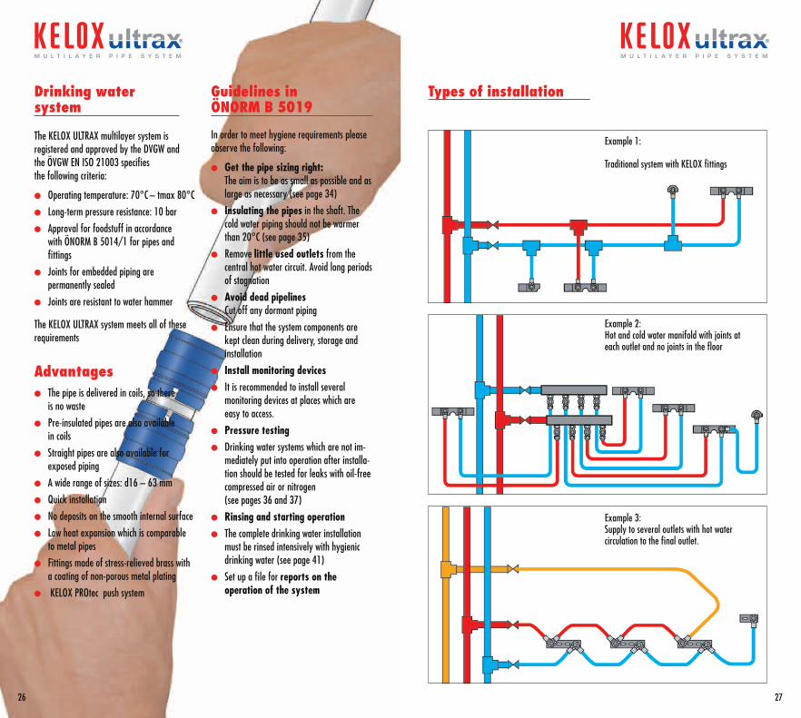
Types of installation
26
m u l t i l a y e r p i p e s y s t e m
27
m u l t i l a y e r p i p e s y s t e m
Example 1:
Traditional system with KELOX fittings
Drinking water system
The KELOX ULTRAX multilayer system is registered and approved by the DVGW and the ÖVGW EN ISO 21003 specifies the following criteria:
l Operating temperature: 70°C – tmax 80°C
l Long-term pressure resistance: 10 bar
l Approval for foodstuff in accordancewith ÖNORM B 5014/1 for pipes and fittings
l Joints for embedded piping are permanently sealed
l Joints are resistant to water hammer
The KELOX ULTRAX system meets all of these requirements
Advantages l The pipe is delivered in coils, so there
is no waste
l Pre-insulated pipes are also available in coils
l Straight pipes are also available for exposed piping
l A wide range of sizes: d16 – 63 mm
l Quick installation
l No deposits on the smooth internal surface
l Low heat expansion which is comparable to metal pipes
l Fittings made of stress-relieved brass with a coating of non-porous metal plating
l KELOX PROtec push system
Guidelines in ÖNORM B 5019
In order to meet hygiene requirements please observe the following:
l Get the pipe sizing right: The aim is to be as small as possible and as large as necessary (see page 34)
l Insulating the pipes in the shaft. The cold water piping should not be warmer than 20°C (see page 35)
l Remove little used outlets from the central hot water circuit. Avoid long periods of stagnation
l Avoid dead pipelinesCut off any dormant piping
l Ensure that the system components are kept clean during delivery, storage and installation
l Install monitoring devicesl It is recommended to install several
monitoring devices at places which are easy to access.
l Pressure testingl Drinking water systems which are not im-
mediately put into operation after installa-tion should be tested for leaks with oil-free compressed air or nitrogen (see pages 36 and 37)
l Rinsing and starting operationl The complete drinking water installation
must be rinsed intensively with hygienic drinking water (see page 41)
l Set up a file for reports on the operation of the system
Example 2:Hot and cold water manifold with joints at each outlet and no joints in the floor
Example 3:Supply to several outlets with hot water circulation to the final outlet.
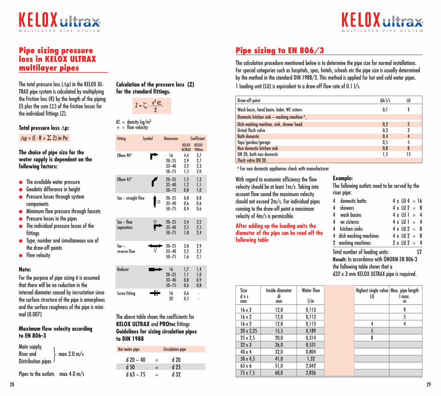
Pipe sizing pressure loss in KELOX ULTRAX multilayer pipes
The total pressure loss (Dp) in the KELOX UL-TRAX pipe system is calculated by multiplying the friction loss (R) by the length of the piping (l) plus the sum (S) of the friction losses for the individual fittings (Z).
Total pressure loss Dp:
Dp = (l . R + S Z) in Pa
The choice of pipe size for the water supply is dependent on the following factors:
l The available water pressurel Geodetic difference in heightl Pressure losses through system componentsl Minimum flow pressure through faucetsl Pressure losses in the pipesl The individual pressure losses of the fittingsl Type, number and simultaneous use of the draw-off pointsl Flow velocity
Note:For the purpose of pipe sizing it is assumed that there will be no reduction in theinternal diameter caused by incrustation since the surface structure of the pipe is amorphous and the surface roughness of the pipe is mini-mal (0.007)
Maximum flow velocity according to EN 806-3
Main supply, Riser and max 2.0 m/sDistribution pipes
}Pipes to the outlets max 4.0 m/s
Calculation of the pressure loss (Z) for the standard fittings.
= density kg/m3
v = flow velocity
The above table shows the coefficients for KELOX ULTRAX and PROtec fittingsGuidelines for sizing circulation pipesto DIN 1988
Hot water pipe Circulation pipe
d 20 – 40 = d 20 d 50 = d 25 d 63 – 75 = d 32
Pipe sizing to EN 806/3The calculation procedure mentioned below is to determine the pipe size for normal installations. For special categories such as hospitals, spas, hotels, schools etc the pipe size is usually determined by the method in the standard DIN 1988/3. This method is applied for hot and cold water pipes.1 loading unit (LU) is equivalent to a draw-off flow rate of 0.1 l/s.
Draw-off point QA l/s LU
Wash basin, hand basin, bidet, WC cistern 0,1 1Domestic kitchen sink – washing machine a , Dish washing machine, sink, shower head 0,2 2Urinal flush valve 0,3 3Bath domestic 0,4 4Taps/garden/garage 0,5 5Non domestic kitchen sink 0,8 8DN 20, bath non domestic 1,5 15Flush valve DN 20a For non domestic appliances check with manufacturer
Size Inside diameter Water flow Loading unit Highest single value Max. pipe length d x s di LU LU l max. mm mm l/m m
16 x 2 12,0 0,113 3 9 16 x 2 12,0 0,113 4 5 16 x 2 12,0 0,113 5 4 4 20 x 2,25 15,5 0,189 10 5 25 x 2,5 20,0 0,314 20 8 32 x 3 26,0 0,531 55 40 x 4 32,0 0,804 180 50 x 4,5 41,0 1,32 540 63 x 6 51,0 2,042 1100 75 x 7,5 60,0 2,826 2200
Z = z · v2
2
28
m u l t i l a y e r p i p e s y s t e m
29
m u l t i l a y e r p i p e s y s t e m
Fitting Symbol Dimension Coefficient KELOX KELOX ULTRAX PROtec Elbow 90° 16 4,4 3,7 20–25 2,9 2,7 32–40 2,2 2,3 50–75 1,5 2,0
Elbow 45° 20–25 1,5 1,3 32–40 1,2 1,1 50–75 0,8 1,0
Tee – straight flow 20–25 0,8 0,8 32–40 0,6 0,6 50–75 0,4 0,6
Tee – flow 20–25 3,4 3,2separation 32–40 2,5 2,5 50–75 1,8 2,4
Tee – 20–25 3,0 2,9reverse flow 32–40 2,2 2,2 50–75 1,6 2,1
Reducer 16 1,7 1,4 20–25 1,1 1,0 32–40 0,8 0,9 50–75 0,6 0,8
Screw fitting 16 0,6 - 20 0,5 -
With regard to economic efficiency the flow velocity should be at least 1m/s. Taking into account flow sound the maximum velocity should not exceed 2m/s. For individual pipes running to the draw-off point a maximum velocity of 4m/s is permissible.
After adding up the loading units the diameter of the pipe can be read off the following table
Example:The following outlets need to be served by the riser pipe:4 domestic baths 4 x LU 4 = 164 showers 4 x LU 2 = 84 wash basins 4 x LU 1 = 44 wc cisterns 4 x LU 1 = 44 kitchen sinks 4 x LU 2 = 84 dish washing machines 4 x LU 2 = 82 washing machines 2 x LU 2 = 4
Total number of loading units: 52Result: In accordance with ÖNORM EN 806-3 the following table shows that ad32 x 3 mm KELOX ULTRAX pipe is required.
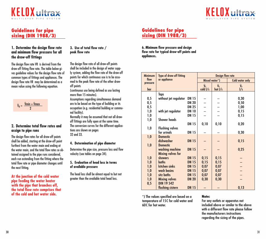
Guidelines for pipe sizing (DIN 1988/3)
1. Determine the design flow rate and minimum flow pressure for allthe draw-off fittings
The design flow rate VR is derived from the draw-off fitting flow rate. The table below gi-ves guideline values for the design flow rate of common types of fittings and appliances. The design flow rate VR may be determined as a mean value using the following equation.
VR = Vmin + Vmax 2
2. Determine total flow rates and assign to pipe runs The design flow rates for all draw-off points shall be added, starting at the draw-off point furthest from the water main and ending at the water main, and the total flow rates so ob-tained assigned to the pipe runs considered, each run extending from the fitting where the total flow rate or pipe diameter changes until the next fitting.
At the junction of the cold water pipe feeding the water heater with the pipe that branches off, the total flow rate comprises that of the cold and hot water side.
3. Use of total flow rate / peak flow rate
The design flow rate of all draw-off points shall be included in the design of water supp-ly system, adding the flow rate of the draw-off points for which continuous use is to be assu-med to the peak flow rate of the other draw-off points (continuous use being defined as use lasting more than 15 minutes).Assumptions regarding simultaneous demand are to be based on the type of building or its occupation (e.g. residential building or commu-nal facility). Normally it may be assumed that not all draw-off fittings are fully open at the same time.The conversion curves for the different applica-tions are shown on pages 32 and 33.
4. Determination of pipe diameter
Determine the pipe size, pressure loss and flow velocity (see tables on page 34).
5. Evaluation of head loss in terms of available pressure
The head loss shall be almost equal to but not greater than the available total head loss.
*) The values specified are based on a temperature of 15C for cold water and 60C for hot water.
Minimum Type of draw-off fitting Design flow rate flow or appliance Mixed water*) Cold water only pressure VR VR VR
bar cold l/s hot l/s l/s
Taps 0,5 without jet regulator DN 15 – – 0,30 0,5 DN 20 – – 0,50 0,5 DN 25 – – 1,00 1,0 with jet regulator DN 10 – – 0,15 1,0 DN 15 – – 0,15 1,0 Shower heads DN 15 0,10 0,10 0,20 1,0 Flushing valves for urinals DN 15 – – 0,30 1,0 Domestic dishwasher DN 15 – – 0,15 1,0 Domestic washing machine DN 15 – – 0,25 Mixing valves for 1,0 showers DN 15 0,15 0,15 – 1,0 baths DN 15 0,15 0,15 – 1,0 kitchen sinks DN 15 0,07 0,07 – 1,0 wash basins DN 15 0,07 0,07 – 1,0 sitz baths DN 15 0,07 0,07 – 1,0 Mixing valves DN 20 0,30 0,30 – 0,5 DIN 19 542 flushing cistern DN 15 – – 0,13
6. Minimum flow pressure and design flow rate for typical draw-off points and appliances.
Guidelines for pipe sizing (DIN 1988/3)
Note: For any outlets or apparatus not included above or similar to the above with a different flow rate please follow the manufacturers instructions regarding the sizing of the pipes.
˙ ˙ ˙
Guidelines for pipe sizing (DIN 1988/3)
6. Minimum flow pressure and design flow rate for typical draw-off points and appliances.
30
m u l t i l a y e r p i p e s y s t e m
31
m u l t i l a y e r p i p e s y s t e m
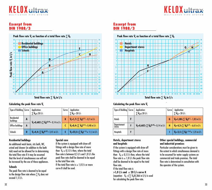
Excerpt from DIN 1988/3
Excerpt from DIN 1988/3
0,1 0,15 0,2 0,3 0,4 0,5 0,7 1 1,5 2 3 4 5 7 10 15 20 30 40 50 70 100 150 200 300 400 5000,1
0,15
0,2
0,3
0,4
0,5
0,7
1
1,5
2
3
45
7
10
15
20
30
B
D
B
E
C
A
0,1
0,15
0,2
0,3
0,4
0,5
0,7
1
1,5
2
3
45
7
10
15
20
30
0,1
0,15
0,2
0,3
0,4
0,5
0,7
1
1,5
2
3
45
7
10
15
20
30
K
F
G HI
0,1
0,15
0,2
0,3
0,4
0,5
0,7
1
1,5
2
3
45
7
10
15
20
30
0,1 0,15 0,2 0,3 0,4 0,5 0,7 1 1,5 2 3 4 5 7 10 15 20 30 40 50 70 100 150 200 300 400 500
Peak flow rate Vs as function of a total flow rate ∑ VR Peak flow rate Vs as function of a total flow rate ∑ VR
Total flow rate ∑ VR in l/s Total flow rate ∑ VR in l/s
Peak
flow
rate
Vs i
n l/
s
Residential buildingsOffice buildingsSchools
HotelsDepartment storesHospitals
Residential buildingsAn additional wash basin, sitz bath, WC, urinal and shower (in addition to the bath tub) need not be allowed for in determining the total flow rate if it may be assumed that the level of simultaneous use will not be increased by the use of these appliances.
SchoolsThe peak flow rate is deemed to be equal to the design flow rate where ∑VR does not exceed 1,5 l/s.
Hotels, department stores and hospitalsIf the system is equipped with draw-off fittings with a design flow rate of more than VR ≥ 0,5 l/s then, where the total flow rate is ≤ 1,0 l/s the peak flow rate shall be deemed to be equal to the total flow rate. If the total flow rate is >1,0 l/s and ≤ 20 l/s curve K (equation: VR =(∑ VR)0,366 in l/s) is used for calculating the peak flow rate.
Special caseIf the system is equipped with draw-off fittings with a design flow rate of more than VR ≥ 0,5 l/s then, where the total flow rate is between 0,5 l/s and 1,0 l/s the peak flow rate shall be deemed to be equal to the total flow rate. If the total flow rate is ≥ 1,0 l/s or more curve B shall be used.
Other special buildings, commercial and industrial premisesParticular considerations must be given to the extent to which simultaneous demand is to be assumed for water supply systems on commercial and trade premises. The total flow rate is determined in consultation with the operator of the system.
32
m u l t i l a y e r p i p e s y s t e m
33
m u l t i l a y e r p i p e s y s t e m
Calculating the peak flow rate Vs Calculating the peak flow rate Vs
Type of Building Curve Application: Curve Application ∑ VR≤ 20 l/s ∑ VR> 20 l/s
Residential A B Vs=1,7∙(∑ VR)0,21– 0,7 in l/s buildings
Office buildings A Vs=0,682∙(∑ VR)0,45– 0,14 in l/s
C Vs=0,4∙(∑ VR)0,54+ 0,48 in l/s
Schools D Vs=4,4∙(∑ VR)0,27– 3,41 in l/s E Vs=22,5∙(∑ VR)– 0,5+ 11,5 in l/s
Type of Building Curve Application: Curve Application ∑ VR≤ 20 l/s ∑ VR> 20 l/s
Hotels F G VS=1,08∙(∑ VR)0,5– 1,83 in l/s
F VS=0,682∙(∑ VR)0,45– 0,14 in l/s H VS=4,3∙(∑ VR)0,27– 6,65 in l/s
Hospitals F I VS=2,5∙(∑ VR)– 0,65+ 1,25 in l/s
Departementstores
Heat insulationDrinking water pipes (cold)Care should be taken to prevent a deterioration in the water quality as a result of warming
Drinking water pipes (hot)The pipes should be insulated in accordance with ÖNORM M 7580. The followingrecommendations are calculated on the as-sumption that the insulation is the LX type.
Surface-mounted installations:ÖNORM M7580 defines exposed piping as in-stallations in front of the wall and in the shaft. Following the requirements of the standard and taking into account the insulating proper-ties of LEXEL (λ at 40°C: 0.038 W/m°C) and the specified insulation thickness the compa-rison of pipe sizes for different materials is shown below:
LEXEL max. outside diameter Insulation Copper Steel KELOX Thickness mm mm mm
9 mm d28 3/4“ d32 13 mm d35 1“ d40
Important! Lexel insulation in sizes LX9 and 13 meet the requirements for pipes up to d40
DIN 1988/2 specifies the minimum insulation thickness for potable water pipes when the medium temperature is assumed to be 10°C
Embedded installationsDue to the much greater flow of heat in the wall ÖNORM M7580 specifies that the insulati-on thickness should be 2/3 of the outside diameter of the pipe and a minimum of 9 mm
LEXEL max. outside diameter Insulation Copper Steel KELOX Thickness mm mm mm
9 mm d15 – d20 13 mm d22 1/2“ d25
Important! Lexel insulation in sizes LX9 and 13 meet the requirements for pipes up to d40
Thickness of Insulation Type of Installation mm
Exposed pipework in an unheated room (e.g. cellar) 4 KM 134
Exposed pipework in a heated room 9 KM 130
Pipework underground with no adjacent hot water pipes 4 KM 134
Pipework underground next to hot water pipes 13 LEXEL-LX 13
Pipework in wall, riser 4 KM 134
Pipework on concrete ceiling 4 KM 134
Dimensionierungund Druckverlust fürKELOX-Modulrohre
Die Berechnung der Einzelwiderständefinden Sie im KELOX-Handbuch.
©
KE K
ELIT
12/
06
KELOX-Modulrohr d14, 16, 18, 20, 25, 32, 40, 50, 63, 75
Die Berechnung der Druckverluste für Wasser(80ϒC) erfolgt gemäß der Formel „Nikuradse”:R = 3,62315 . 103 . m1,70651 . di -4,64237
Rohrrauhigkeit: 0,007 mm
900600 700 80010 50 60 70 80 901004020 30 200
150
15
1500
150
9876
5
4
3
2
10,90,80,70,6
0,5
0,4
0,3
0,2
0,10,090,080,070,06
0,05
0,04
0,03
30
20
10
40
1,5
15
2000
0
1000
0
1500
0
1000 1500 2000
0,5
1,0
1,5
2,02,5
3,0
d75x7,5
d16x2
d20x2,25
d25x2,5
d32x3
d40x4
d50x4,5d63x6
4,0
Flow
rat
e (L
itre/
sec)
Water velocity (m/sec)
PA/m
mm/WS300 400 500
2000
1000
5000
4000
3000
6000
7000
8000
9000900
800
700
600
500
400
300
200
100
Water velocity (m/sec)
Flow rate (Litre/sec)
Pressure loss PA/m
Pressure loss PA/m
The pressure losses are calculated according to the Nikuradse formula: R = 3,62315 · 103 · m· 1,70651 · di –4,64237
Surface roughness: 0.007 mm
R= pressure loss (Pa/m)m· = flow rate (l/h)di = pipe inside diameter (mm)
Pipe sizing and pressure losses
The method for calculating the pressure loss of the individual fittings is described on page 28KELOX ULTRAX multilayer pipe d: 16, 20, 25, 32, 40, 50, 63, 75
34 35
m u l t i l a y e r p i p e s y s t e mm u l t i l a y e r p i p e s y s t e m
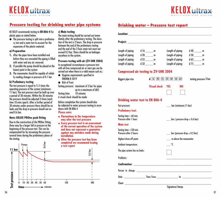
KE KELIT recommends testing to EN 806-4 for plastic pipes as stated below.l The pressure testing is split into a prelimina-
ry test and a main test to account for the expansion of the plastic material.
a) Preparation1. After the pipes have been installed and
before they are concealed the piping is filled with water and any air removed.
2. If possible the pump should be placed at the lowest point in the system
3. The manometer should be capable of reliab-ly reading changes in pressure of 0.1 bar
b) Preliminary testingThe test pressure is equal to 1.1 times the operating pressure of the system (minimum: 11 bar). The test pressure must be built up over a period of 30 minutes. Within the 30 minutes the pressure should be adjusted 2 times (each time 10 mins apart). After a further period of 30 minutes under pressure there should be no leaks and the drop in pressure should not ex-ceed 0.6 bar.
Note: KELOX PROtec push fittingDue to the construction of the PROtec fitting there may be a larger fall in pressure at the beginning of the pressure test. This can be compensated for by increasing the pressure several times during the preliminary phase of the testing.
0 10 18020 30 40 50 60 120
minutestime
Pumps
11 bar 0,6
bar
0,2
bar
Test
pres
sure
Drinking water – Pressure test report
Location: ______________________________________________________________________________________
Project: _______________________________________________________________________________________
Length of piping: d 16 ________ m Length of piping: d 40 ________ mLength of piping: d 20 ________ m Length of piping: d 50 ________ mLength of piping: d 25 ________ m Length of piping: d 63 ________ mLength of piping: d 32 ________ m Length of piping: d 75 ________ m
Compressed air testing to ZV-SHK 2004
Biggest pipe size d l16 l20 l25 l32 l40 l50 l63 testing pressure 3 bar
Visual check YES NO
Drinking water test to EN 806-4Test pressure: _____ bar (minimum:11 bar)
Preliminary test:
Testing time = 60 min.Pressure after 1 hour: _____ bar ( pressure drop ≤ 0.6 bar)
Main test
Testing time =120 minPressure after 2 hours: _____ bar (pressure drop ≤ 0.2 bar)
Highest draw-off point: _____ m above the manometer
Ambient temperature: _____ °C
The pipe system has no leaks:
Problems: _____________________________________________
Confirmation: ________________________________________________________________________________
Person in charge: _____________________________________________________________________________
Date: ______________________ Time: from ______________________ to ______________________________
Client __________________________________________________________________________________________
Signature/stamp
c) Main testing The main testing should be carried out imme-diately after the preliminary testing. The dura-tion of the test is 2 hours. The drop in pressure between the end of the preliminary testing and the end of the 2 hour main test must not exceed 0.2 bar. There should be no leakages anywhere in the system.
Pressure testing with air (ZV-SHK 2004)In exceptional circumstances a pressure test with oil-free compressed air or inert gas can be carried out when there is a valid reason such as.:l Hygiene requirements specified in
ÖNORM B 5019l Risk of frostTesting pressure: maximum of 3 bar for pipes up to a maximum of d63 Testing time: 10 minutesA visual check should be made
Before completion the system should also be subjected to water pressure testing in accor-dance with EN 806-4Please note:l Fluctuations in the temperature
may alter the test pressurel Every pressure test is an assessment
of the current operation of the system and does not represent a guarantee against any mistakes made during installation
l After the pressure test has been completed we recommend issuing a test report
Pressure testing for drinking water pipe systems
36
m u l t i l a y e r p i p e s y s t e m
37
m u l t i l a y e r p i p e s y s t e m
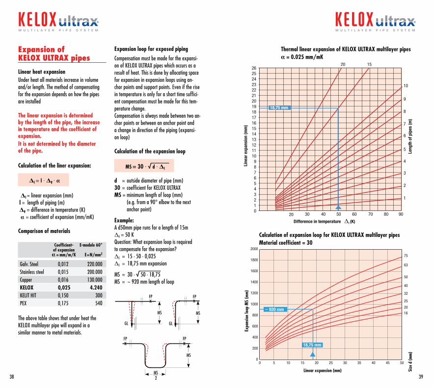
Expansion of KELOX ULTRAX pipes
Linear heat expansionUnder heat all materials increase in volume and/or length. The method of compensating for the expansion depends on how the pipes are installed
The linear expansion is determined by the length of the pipe, the increase in temperature and the coefficient of expansion.It is not determined by the diameter of the pipe.
Calculation of the liner expansion:
Δl = l · Δt · α
Δl = linear expansion (mm) l = length of piping (m) Δt = difference in temperature (K) α= coefficient of expansion (mm/mK)
Comparison of materials
Coefficient- E-module 60° of expansion α = mm/m/K E=N/mm2
Galv. Steel 0,012 220.000Stainless steel 0,015 200.000Copper 0,016 130.000KELOX 0,025 4.240KELIT HIT 0,150 300PEX 0,175 540
The above table shows that under heat the KELOX multilayer pipe will expand in asimilar manner to metal materials.
Expansion loop for exposed piping
Compensation must be made for the expansi-on of KELOX ULTRAX pipes which occurs as a result of heat. This is done by allocating space for expansion in expansion loops using an-chor points and support points. Even if the rise in temperature is only for a short time suffici-ent compensation must be made for this tem-perature change.Compensation is always made between two an-chor points or between an anchor point and a change in direction of the piping (expansi-on loop)
Calculation of the expansion loop
MS = 30 · √d · Δl
d = outside diameter of pipe (mm)30 = coefficient for KELOX ULTRAXMS = minimum length of loop (mm) (e.g. from a 90° elbow to the next anchor point)
Example:A d50mm pipe runs for a length of 15m Δt = 50 K Question: What expansion loop is required to compensate for the expansion?Δl = 15 · 50 · 0,025Δl = 18,75 mm expansion
MS = 30 · √50 · 18,75MS = ~ 920 mm length of loop
x
xx
xFP FP
MS MS
MS
MS2
GL GL
FP FP
38
m u l t i l a y e r p i p e s y s t e m
39
m u l t i l a y e r p i p e s y s t e m
020 30 40 50 60 70 80 90
123456789
1011121314151617181920212223242526
Line
ar e
xpan
sion
(mm
)
Leng
th o
f pip
es (m
)
Difference in temperature Δt (K)
1
2
3
4
5
6
7
8
9
10
1520
18,75 mm
Thermal linear expansion of KELOX ULTRAX multilayer pipesα = 0.025 mm/mK
Calculation of expansion loop for KELOX ULTRAX multilayer pipesMaterial coefficient = 30
0 5 10 15 20 25 30 35 40 45 50
75
63
50
40
32
25
20
16
0
200
400
600
800
1000
1200
1400
1600
1800
2000
Size
d (m
m)
Linear expansion (mm)
~ 920 mm
18,75 mm
Expa
nsio
n lo
op M
S (m
m)
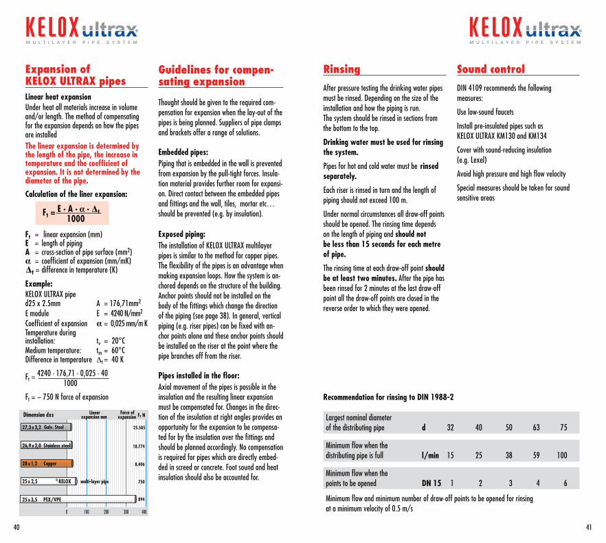
Expansion of KELOX ULTRAX pipesLinear heat expansionUnder heat all materials increase in volume and/or length. The method of compensating for the expansion depends on how the pipes are installedThe linear expansion is determined by the length of the pipe, the increase in temperature and the coefficient of expansion. It is not determined by the diameter of the pipe.
Calculation of the liner expansion:
Ft = E · A · α · ∆ t 1000
Ft = linear expansion (mm)E = length of pipingA = cross-section of pipe surface (mm2)α= coefficient of expansion (mm/mK)∆ t = difference in temperature (K)
Example:KELOX ULTRAX pipe d25 x 2.5mm A = 176,71mm2
E module E = 4240 N/mm2
Coefficient of expansion α = 0,025 mm/m KTemperature during installation: tv = 20°CMedium temperature: tm = 60°CDifference in temperature Dt = 40 K
Ft = 4240 · 176,71 · 0,025 · 40 1000
Ft = ~ 750 N force of expansion
0 100 200 300 400
Dimension dxs
PEX/VPE25x3,5
Copper28x1,2
Stainless steel26,9x2,0
KELOX® multi-layer pipe25x 2,5
Galv. Steel27,3x3,2
894
8.406
18.774
750
25.585
Linear expansion mm
Force of expansion tF N
Guidelines for compen-sating expansion
Thought should be given to the required com-pensation for expansion when the lay-out of the pipes is being planned. Suppliers of pipe clamps and brackets offer a range of solutions.
Embedded pipes:Piping that is embedded in the wall is prevented from expansion by the pull-tight forces. Insula-tion material provides further room for expansi-on. Direct contact between the embedded pipes and fittings and the wall, tiles, mortar etc… should be prevented (e.g. by insulation).
Exposed piping:The installation of KELOX ULTRAX multilayer pipes is similar to the method for copper pipes. The flexibility of the pipes is an advantage when making expansion loops. How the system is an-chored depends on the structure of the building. Anchor points should not be installed on the body of the fittings which change the direction of the piping (see page 38). In general, vertical piping (e.g. riser pipes) can be fixed with an-chor points alone and these anchor points should be installed on the riser at the point where the pipe branches off from the riser.
Pipes installed in the floor: Axial movement of the pipes is possible in the insulation and the resulting linear expansion must be compensated for. Changes in the direc-tion of the insulation at right angles provides an opportunity for the expansion to be compensa-ted for by the insulation over the fittings and should be planned accordingly. No compensation is required for pipes which are directly embed-ded in screed or concrete. Foot sound and heat insulation should also be accounted for.
Rinsing
After pressure testing the drinking water pipes must be rinsed. Depending on the size of the installation and how the piping is run.The system should be rinsed in sections from the bottom to the top.
Drinking water must be used for rinsing the system.
Pipes for hot and cold water must be rinsed separately.
Each riser is rinsed in turn and the length of piping should not exceed 100 m.
Under normal circumstances all draw-off points should be opened. The rinsing time depends on the length of piping and should not be less than 15 seconds for each metre of pipe.
The rinsing time at each draw-off point should be at least two minutes. After the pipe has been rinsed for 2 minutes at the last draw-off point all the draw-off points are closed in the reverse order to which they were opened.
Sound control
DIN 4109 recommends the following measures:
Use low-sound faucets
Install pre-insulated pipes such as KELOX ULTRAX KM130 and KM134
Cover with sound-reducing insulation (e.g. Lexel)
Avoid high pressure and high flow velocity
Special measures should be taken for sound sensitive areas
Recommendation for rinsing to DIN 1988-2
Largest nominal diameterof the distributing pipe d 32 40 50 63 75
Minimum flow when the distributing pipe is full l/min 15 25 38 59 100
Minimum flow when the points to be opened DN 15 1 2 3 4 6
Minimum flow and minimum number of draw-off points to be opened for rinsingat a minimum velocity of 0.5 m/s
40
m u l t i l a y e r p i p e s y s t e m
41
m u l t i l a y e r p i p e s y s t e m
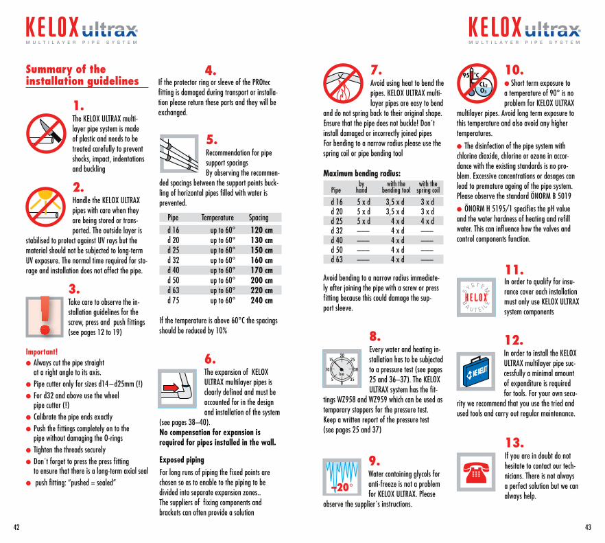
Summary of the installation guidelines
1. The KELOX ULTRAX multi- layer pipe system is made of plastic and needs to be treated carefully to prevent shocks, impact, indentations and buckling
2.Handle the KELOX ULTRAX pipes with care when they are being stored or trans-ported. The outside layer is
stabilised to protect against UV rays but the material should not be subjected to long-term UV exposure. The normal time required for sto-rage and installation does not affect the pipe.
3.Take care to observe the in-stallation guidelines for the screw, press and push fittings (see pages 12 to 19)
Important!l Always cut the pipe straight
at a right angle to its axis.l Pipe cutter only for sizes d14 – d25mm (!)l For d32 and above use the wheel
pipe cutter (!)l Calibrate the pipe ends exactlyl Push the fittings completely on to the
pipe without damaging the O-ringsl Tighten the threads securelyl Don´t forget to press the press fitting
to ensure that there is a long-term axial seall push fitting: “pushed = sealed”
5.Recommendation for pipe support spacingsBy observing the recommen-
ded spacings between the support points buck-ling of horizontal pipes filled with water is prevented.
Pipe Temperature Spacing
d 16 up to 60° 120 cm d 20 up to 60° 130 cm d 25 up to 60° 150 cm d 32 up to 60° 160 cm d 40 up to 60° 170 cm d 50 up to 60° 200 cm d 63 up to 60° 220 cm d 75 up to 60° 240 cm
If the temperature is above 60°C the spacings should be reduced by 10%
6.The expansion of KELOX ULTRAX multilayer pipes is clearly defined and must be accounted for in the design and installation of the system
(see pages 38–40).No compensation for expansion is required for pipes installed in the wall.
Exposed pipingFor long runs of piping the fixed points are chosen so as to enable to the piping to be divided into separate expansion zones..The suppliers of fixing components and brackets can often provide a solution
7.Avoid using heat to bend the pipes. KELOX ULTRAX multi-layer pipes are easy to bend
and do not spring back to their original shape.Ensure that the pipe does not buckle! Don´t install damaged or incorrectly joined pipesFor bending to a narrow radius please use the spring coil or pipe bending tool
Maximum bending radius: by with the with the Pipe hand bending tool spring coil
d 16 5 x d 3,5 x d 3 x dd 20 5 x d 3,5 x d 3 x dd 25 5 x d 4 x d 4 x dd 32 ––– 4 x d –––d 40 ––– 4 x d –––d 50 ––– 4 x d –––d 63 ––– 4 x d –––
Avoid bending to a narrow radius immediate-ly after joining the pipe with a screw or press fitting because this could damage the sup-port sleeve.
8.Every water and heating in-stallation has to be subjected to a pressure test (see pages 25 and 36–37). The KELOX ULTRAX system has the fit-
tings WZ958 and WZ959 which can be used as temporary stoppers for the pressure test.Keep a written report of the pressure test (see pages 25 and 37)
9.Water containing glycols for anti-freeze is not a problem for KELOX ULTRAX. Please
observe the supplier´s instructions.
10.l Short term exposure to a temperature of 90° is no problem for KELOX ULTRAX
multilayer pipes. Avoid long term exposure to this temperature and also avoid any higher temperatures.
l The disinfection of the pipe system with chlorine dioxide, chlorine or ozone in accor-dance with the existing standards is no pro-blem. Excessive concentrations or dosages can lead to premature ageing of the pipe system. Please observe the standard ÖNORM B 5019
l ÖNORM H 5195/1 specifies the pH value and the water hardness of heating and refill water. This can influence how the valves and control components function.
11.In order to qualify for insu-rance cover each installation must only use KELOX ULTRAX system components
12. In order to install the KELOX ULTRAX multilayer pipe suc-cessfully a minimal amount of expenditure is required for tools. For your own secu-
rity we recommend that you use the tried and used tools and carry out regular maintenance.
13. If you are in doubt do not hesitate to contact our tech-nicians. There is not always a perfect solution but we can always help.
4. If the protector ring or sleeve of the PROtec fitting is damaged during transport or installa-tion please return these parts and they will be exchanged.
42
m u l t i l a y e r p i p e s y s t e m
43
m u l t i l a y e r p i p e s y s t e m
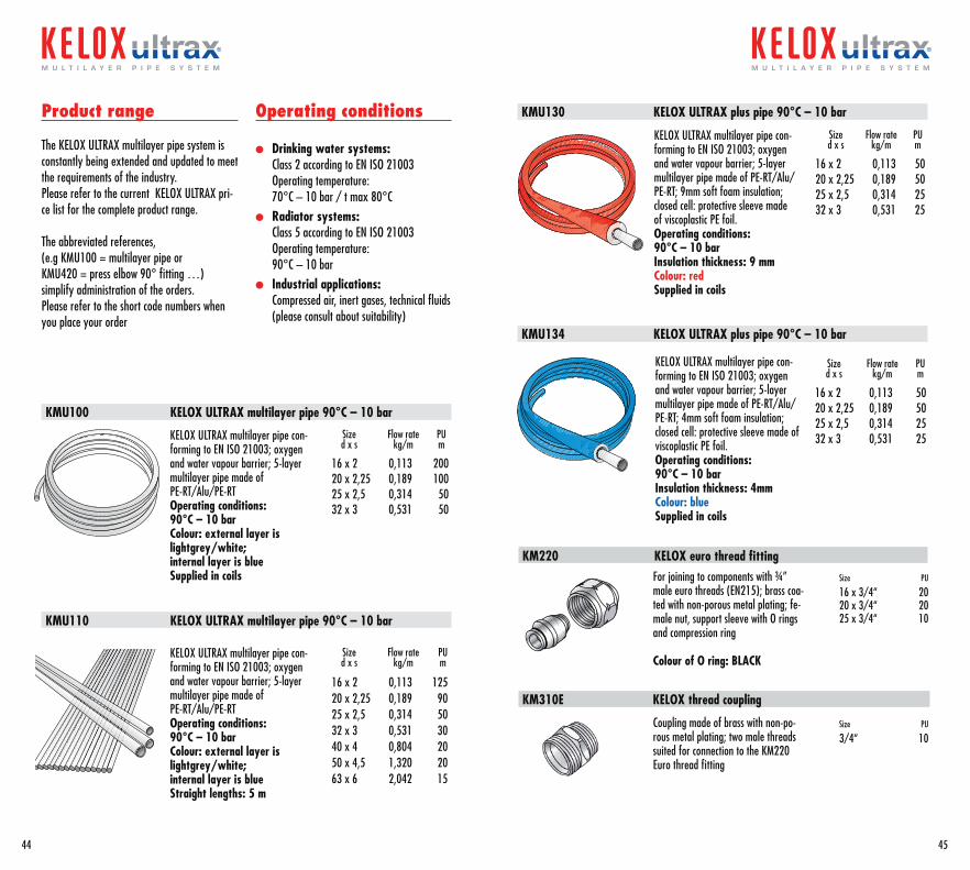
Product range
The KELOX ULTRAX multilayer pipe system is constantly being extended and updated to meet the requirements of the industry.Please refer to the current KELOX ULTRAX pri-ce list for the complete product range.
The abbreviated references, (e.g KMU100 = multilayer pipe or KMU420 = press elbow 90° fitting …)simplify administration of the orders.Please refer to the short code numbers when you place your order
Operating conditions
l Drinking water systems:Class 2 according to EN ISO 21003 Operating temperature: 70°C – 10 bar / t max 80°C
l Radiator systems:Class 5 according to EN ISO 21003 Operating temperature: 90°C – 10 bar
l Industrial applications:Compressed air, inert gases, technical fluids (please consult about suitability)
KMU100 KELOX ULTRAX multilayer pipe 90°C – 10 bar
KMU110 KELOX ULTRAX multilayer pipe 90°C – 10 bar
KMU130 KELOX ULTRAX plus pipe 90°C – 10 bar
KMU134 KELOX ULTRAX plus pipe 90°C – 10 bar
KELOX ULTRAX multilayer pipe con-forming to EN ISO 21003; oxygen and water vapour barrier; 5-layer multilayer pipe made of PE-RT/Alu/PE-RTOperating conditions:90°C – 10 bar Colour: external layer is lightgrey/white; internal layer is blueSupplied in coils
KELOX ULTRAX multilayer pipe con-forming to EN ISO 21003; oxygen and water vapour barrier; 5-layer multilayer pipe made of PE-RT/Alu/PE-RTOperating conditions:90°C – 10 bar Colour: external layer is lightgrey/white; internal layer is blueStraight lengths: 5 m
Size Flow rate PU d x s kg/m m
16 x 2 0,113 20020 x 2,25 0,189 10025 x 2,5 0,314 5032 x 3 0,531 50
Size Flow rate PU d x s kg/m m
16 x 2 0,113 12520 x 2,25 0,189 9025 x 2,5 0,314 5032 x 3 0,531 3040 x 4 0,804 2050 x 4,5 1,320 2063 x 6 2,042 15
Size Flow rate PU d x s kg/m m
16 x 2 0,113 5020 x 2,25 0,189 5025 x 2,5 0,314 2532 x 3 0,531 25
KELOX ULTRAX multilayer pipe con-forming to EN ISO 21003; oxygen and water vapour barrier; 5-layer multilayer pipe made of PE-RT/Alu/PE-RT; 9mm soft foam insulation; closed cell: protective sleeve made of viscoplastic PE foil.Operating conditions:90°C – 10 bar Insulation thickness: 9 mmColour: redSupplied in coils
KELOX ULTRAX multilayer pipe con-forming to EN ISO 21003; oxygen and water vapour barrier; 5-layer multilayer pipe made of PE-RT/Alu/PE-RT; 4mm soft foam insulation; closed cell: protective sleeve made of viscoplastic PE foil.Operating conditions:90°C – 10 bar Insulation thickness: 4mmColour: blueSupplied in coils
Size Flow rate PU d x s kg/m m
16 x 2 0,113 5020 x 2,25 0,189 5025 x 2,5 0,314 2532 x 3 0,531 25
For joining to components with ¾” male euro threads (EN215); brass coa-ted with non-porous metal plating; fe-male nut, support sleeve with O rings and compression ring
Colour of O ring: BLACK
Size PU
16 x 3/4“ 20 20 x 3/4“ 20 25 x 3/4“ 10
Size PU
3/4“ 10
Coupling made of brass with non-po-rous metal plating; two male threads suited for connection to the KM220 Euro thread fitting
KM310E KELOX thread coupling
KM220 KELOX euro thread fitting
44
m u l t i l a y e r p i p e s y s t e m
45
m u l t i l a y e r p i p e s y s t e m
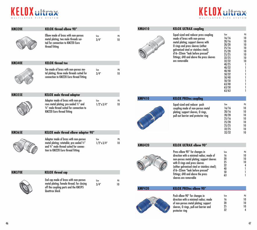
KM320E KELOX thread elbow 90°
Elbow made of brass with non-porous metal plating; two male threads sui-ted for connection to KM220 Euro thread fitting
Size PU
3/4“ 10
KM340E KELOX thread tee
KM355E KELOX male thread adaptor
KM365E KELOX male thread elbow adaptor 90°
KM370E KELOX thread cap
KMU410 KELOX ULTRAX coupling
KMP410 KELOX PROtec coupling
Tee made of brass with non-porous me-tal plating; three male threads suited for connection to KM220 Euro thread fitting
Size PU
3/4“ 10
Adaptor made of brass with non-po-rous metal plating; pre-sealed ½” and ¾” male thread suited for connection to KM220 Euro thread fitting
Size PU
1/2“x 3/4“ 10
Adaptor made of brass with non-porous metal plating; rotatable; pre-sealed ½” and ¾” male thread suited for connec-tion to KM220 Euro thread fitting
Size PU
1/2“x 3/4“ 10
End cap made of brass with non-porous metal plating; female thread; for closing off the coupling parts and the KM595 Quattrox block
Size PU
3/4“ 10
Size PU
16/16 10 20/16 10 20/20 10 25/16 10 25/20 10 25/25 10 32/25 10 32/32 10 40/25 1 40/32 1 40/40 1 50/32 1 50/40 1 50/50 1 63/40 1 63/50 1 63/63 1
Equal-sized and reducer press coupling made of brass with non-porous metal plating; support sleeves with O rings and press sleeves (either galvanised steel or stainless steel);d16–32mm “leak before pressed” fittings; d40 and above the press sleeves are removable
Equal-sized and reducer push coupling made of non-porous metal plating; support sleeves, O rings, pull-out barrier and protector ring
Size PU
16/16 10 20/16 10 20/20 10 25/16 10 25/20 10 25/25 10 32/25 10 32/32 10
Press elbow 90° for changes in direction with a minimal radius; made of non-porous metal plating; support sleeves with O rings and press sleeves (either galvanised steel or stainless steel); d16–32mm “leak before pressed” fittings; d40 and above the press sleeves are removable
Size PU
16 10 20 10 25 10 32 4 40 1 50 1 63 1
KMU420 KELOX ULTRAX elbow 90°
KMP420 KELOX PROtec elbow 90°
Push elbow 90° for changes in direction with a minimal radius; made of non-porous metal plating; support sleeves, O rings, pull-out barrier and protector ring
Size PU
16 10 20 10 25 10 32 4
46
m u l t i l a y e r p i p e s y s t e m
47
m u l t i l a y e r p i p e s y s t e m
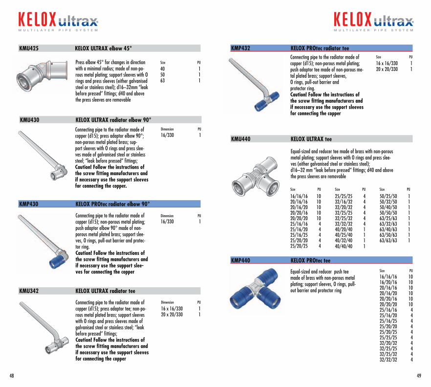
KMU425 KELOX ULTRAX elbow 45°
KMP430 KELOX PROtec radiator elbow 90°
KMU342 KELOX ULTRAX radiator tee
KMP432 KELOX PROtec radiator tee
Press elbow 45° for changes in direction with a minimal radius; made of non-po-rous metal plating; support sleeves with O rings and press sleeves (either galvanised steel or stainless steel); d16–32mm “leak before pressed” fittings; d40 and above the press sleeves are removable
Size PU
40 1 50 1 63 1
KMU430 KELOX ULTRAX radiator elbow 90°
Connecting pipe to the radiator made of copper (d15); press adaptor elbow 90°; non-porous metal plated brass; sup-port sleeves with O rings and press slee-ves made of galvanised steel or stainless steel; “leak before pressed” fittings; Caution! Follow the instructions of the screw fitting manufacturers and if necessary use the support sleeves for connecting the copper.
Dimension PU
16/330 1
Connecting pipe to the radiator made of copper (d15); non-porous metal plating; push adaptor elbow 90° made of non-porous metal plated brass; support slee-ves, O rings, pull-out barrier and protec-tor ring. Caution! Follow the instructions of the screw fitting manufacturers and if necessary use the support slee-ves for connecting the copper
Dimension PU 16/330 1
Connecting pipe to the radiator made of copper (d15); press adaptor tee; non-po-rous metal plated brass; support sleeves with O rings and press sleeves made of galvanised steel or stainless steel; “leak before pressed” fittings; Caution! Follow the instructions of the screw fitting manufacturers and if necessary use the support sleeves for connecting the copper
Dimension PU
16 x 16/330 1 20 x 20/330 1
Connecting pipe to the radiator made of copper (d15); non-porous metal plating; push adaptor tee made of non-porous me-tal plated brass; support sleeves, O rings, pull-out barrier and protector ring. Caution! Follow the instructions of the screw fitting manufacturers and if necessary use the support sleeves for connecting the copper
Size PU
16 x 16/330 1 20 x 20/330 1
KMU440 KELOX ULTRAX tee
Size PU
16/16/16 1020/16/16 1020/16/20 1020/20/16 1020/20/20 1025/16/16 425/16/20 4 25/16/25 425/20/20 425/20/25 4
Size PU
25/25/25 432/16/32 432/20/32 432/25/25 432/25/32 432/32/32 440/20/40 140/25/40 140/32/40 140/40/40 1
Size PU
50/25/50 150/32/50 150/40/50 150/50/50 163/25/63 163/32/63 163/40/63 163/50/63 163/63/63 1
Equal-sized and reducer tee made of brass with non-porous metal plating; support sleeves with O rings and press slee-ves (either galvanised steel or stainless steel);d16–32 mm “leak before pressed” fittings; d40 and above the press sleeves are removable
Equal-sized and reducer push tee made of brass with non-porous metal plating; support sleeves, O rings, pull-out barrier and protector ring
Size PU
16/16/16 10 16/20/16 10 20/16/16 10 20/16/20 10 20/20/16 10 20/20/20 10 25/16/16 4 25/16/20 4 25/16/25 4 25/20/20 4 25/20/25 4 25/25/25 4 32/20/32 4 32/25/25 4 32/25/32 4 32/32/32 4
KMP440 KELOX PROtec tee
48
m u l t i l a y e r p i p e s y s t e m
49
m u l t i l a y e r p i p e s y s t e m
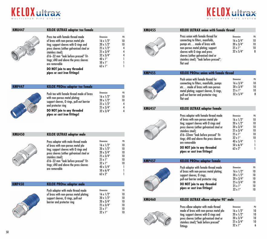
Press tee with female thread made of brass with non-porous metal pla-ting; support sleeves with O rings and press sleeves (either galvanised steel or stainless steel);d16–32 mm “leak before pressed” fit-tings; d40 and above the press sleeves are removableDO NOT join to any threaded pipes or cast iron fittings!
Dimension PU
16 x 1/2“ 10 20 x 1/2“ 10 25 x 1/2“ 4 25 x 3/4“ 4 32 x 3/4“ 4 40 x 1“ 1 50 x 1“ 1 63 x 1“ 1
KMU447 KELOX ULTRAX adaptor tee female
Push tee with female thread made of brass with non-porous metal plating; support sleeves, O rings, pull-out barrier and protector ringDO NOT join to any threaded pipes or cast iron fittings!
Dimension PU
16 x 1/2“ 10 20 x 1/2“ 10 25 x 1/2“ 4 25 x 3/4“ 4 32 x 3/4“ 4
KMP447 KELOX PROtec adaptor tee female
Press adaptor with male thread made of brass with non-porous metal pla-ting; support sleeves with O rings and press sleeves (either galvanised steel or stainless steel);d16–32 mm “leak before pressed” fit-tings; d40 and above the press sleeves are removable
Dimension PU
16 x 1/2“ 10 20 x 1/2“ 10 20 x 3/4“ 10 25 x 3/4“ 10 25 x 1“ 10 32 x 1“ 10 40 x 5/4“ 1 50 x 6/4“ 1 63 x 2“ 1
KMU450 KELOX ULTRAX adaptor male
Push adaptor with male thread made of brass with non-porous metal plating; support sleeves, O rings, pull-out barrier and protector ring
Dimension PU
16 x 1/2“ 10 20 x 1/2“ 10 20 x 3/4“ 10 25 x 3/4“ 10 25 x 1“ 10 32 x 1“ 10
KMP450 KELOX PROtec adaptor male
Press union with female thread for connecting to filters, manifolds, pumps etc… made of brass with non-porous metal plating; support sleeves with O rings and press sleeves (either galvanised steel or stainless steel); “leak before pressed”; flat seal
Dimension PU
16 x 3/4“ 10 20 x 3/4“ 10 25 x 1“ 10 32 x 5/4“ 8
KMU455 KELOX ULTRAX union with female thread
Push union with female thread for connecting to filters, manifolds, pumps etc… made of brass with non-porous metal plating; support sleeves, O rings, pull-out barrier and protector ring; flat seal
Dimension PU
16 x 3/4“ 10 20 x 3/4“ 10 25 x 1“ 10 32 x 5/4“ 8
KMP455 KELOX PROtec union with female thread
Press adaptor with female thread made of brass with non-porous metal pla-ting; support sleeves with O rings and press sleeves (either galvanised steel or stainless steel);d16–32mm “leak before pressed” fit-tings; d40 and above the press sleeves are removableDO NOT join to any threaded pipes or cast iron fittings!
Dimension PU
16 x 1/2“ 10 20 x 1/2“ 10 20 x 3/4“ 10 25 x 3/4“ 10 25 x 1“ 10 32 x 1“ 10 40 x 5/4“ 1 50 x 6/4“ 1 63 x 2“ 1
KMU457 KELOX ULTRAX adaptor female
Push adaptor with female thread made of brass with non-porous metal plating; support sleeves, O rings, pull-out barrier and protector ringDO NOT join to any threaded pipes or cast iron fittings!
Dimension PU
16 x 1/2“ 10 20 x 1/2“ 10 20 x 3/4“ 10 25 x 3/4“ 10 25 x 1“ 10 32 x 1“ 10
KMP457 KELOX PROtec adaptor female
Press elbow adaptor with male thread made of brass with non-porous metal pla-ting; support sleeves with O rings and press sleeves (either galvanised steel or stainless steel);“leak before pressed” fittings
Dimension PU
16 x 1/2“ 10 20 x 1/2“ 10 20 x 3/4“ 10 25 x 3/4“ 10 32 x 1“ 6
KMU460 KELOX ULTRAX elbow adaptor 90° male
50
m u l t i l a y e r p i p e s y s t e m m u l t i l a y e r p i p e s y s t e m
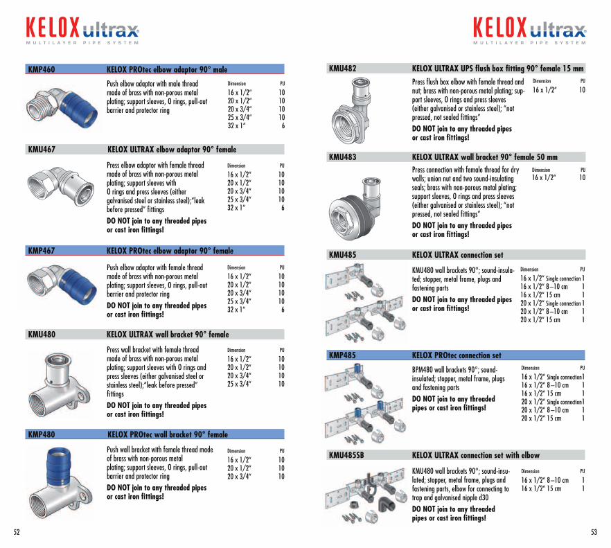
Push elbow adaptor with male thread made of brass with non-porous metal plating; support sleeves, O rings, pull-out barrier and protector ring
Dimension PU
16 x 1/2“ 10 20 x 1/2“ 10 20 x 3/4“ 10 25 x 3/4“ 10 32 x 1“ 6
KMP460 KELOX PROtec elbow adaptor 90° male
Press elbow adaptor with female thread made of brass with non-porous metal plating; support sleeves with O rings and press sleeves (either galvanised steel or stainless steel);“leak before pressed” fittings DO NOT join to any threaded pipes or cast iron fittings!
Dimension PU
16 x 1/2“ 10 20 x 1/2“ 10 20 x 3/4“ 10 25 x 3/4“ 10 32 x 1“ 6
KMU467 KELOX ULTRAX elbow adaptor 90° female
Push elbow adaptor with female thread made of brass with non-porous metal plating; support sleeves, O rings, pull-out barrier and protector ringDO NOT join to any threaded pipes or cast iron fittings!
Dimension PU
16 x 1/2“ 10 20 x 1/2“ 10 20 x 3/4“ 10 25 x 3/4“ 10 32 x 1“ 6
KMP467 KELOX PROtec elbow adaptor 90° female
KMU482 KELOX ULTRAX UPS flush box fitting 90° female 15 mm
KMU483 KELOX ULTRAX wall bracket 90° female 50 mm
KMU485 KELOX ULTRAX connection set
KMU480 KELOX ULTRAX wall bracket 90° female
KMP480 KELOX PROtec wall bracket 90° female
Press wall bracket with female thread made of brass with non-porous metal plating; support sleeves with O rings and press sleeves (either galvanised steel or stainless steel);“leak before pressed” fittings DO NOT join to any threaded pipes or cast iron fittings!
Dimension PU
16 x 1/2“ 10 20 x 1/2“ 10 20 x 3/4“ 10 25 x 3/4“ 10
Push wall bracket with female thread made of brass with non-porous metal plating; support sleeves, O rings, pull-out barrier and protector ringDO NOT join to any threaded pipes or cast iron fittings!
Dimension PU
16 x 1/2“ 10 20 x 1/2“ 10 20 x 3/4“ 10
Press flush box elbow with female thread and nut; brass with non-porous metal plating; sup-port sleeves, O rings and press sleeves (either galvanised or stainless steel); “not pressed, not sealed fittings”DO NOT join to any threaded pipes or cast iron fittings!
Dimension PU
16 x 1/2“ 10
Press connection with female thread for dry walls; union nut and two sound-insulating seals; brass with non-porous metal plating; support sleeves, O rings and press sleeves (either galvanised or stainless steel); “not pressed, not sealed fittings”DO NOT join to any threaded pipes or cast iron fittings!
Dimension PU 16 x 1/2“ 10
KMU480 wall brackets 90°; sound-insula-ted; stopper, metal frame, plugs and fastening partsDO NOT join to any threaded pipes or cast iron fittings!
Dimension PU
16 x 1/2“ Single connection 1 16 x 1/2“ 8 –10 cm 1 16 x 1/2“ 15 cm 1 20 x 1/2“ Single connection 1 20 x 1/2“ 8 –10 cm 1 20 x 1/2“ 15 cm 1
BPM480 wall brackets 90°; sound- insulated; stopper, metal frame, plugs and fastening partsDO NOT join to any threaded pipes or cast iron fittings!
Dimension PU
16 x 1/2“ Single connection 1 16 x 1/2“ 8 –10 cm 1 16 x 1/2“ 15 cm 1 20 x 1/2“ Single connection 1 20 x 1/2“ 8 –10 cm 1 20 x 1/2“ 15 cm 1
KMP485 KELOX PROtec connection set
KMU480 wall brackets 90°; sound-insu-lated; stopper, metal frame, plugs and fastening parts, elbow for connecting to trap and galvanised nipple d30DO NOT join to any threaded pipes or cast iron fittings!
Dimension PU
16 x 1/2“ 8 –10 cm 1 16 x 1/2“ 15 cm 1
KMU485SB KELOX ULTRAX connection set with elbow
52
m u l t i l a y e r p i p e s y s t e m
53
m u l t i l a y e r p i p e s y s t e m
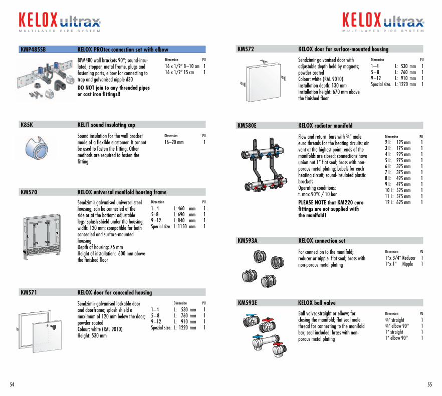
BPM480 wall brackets 90°; sound-insu-lated; stopper, metal frame, plugs and fastening parts, elbow for connecting to trap and galvanised nipple d30DO NOT join to any threaded pipes or cast iron fittings!!
Dimension PU
16 x 1/2“ 8 –10 cm 1 16 x 1/2“ 15 cm 1
Sound insulation for the wall bracket made of a flexible elastomer. It cannot be used to fasten the fitting. Other methods are required to fasten the fitting.
Dimension PU
16–20 mm 1
KMP485SB KELOX PROtec connection set with elbow
K85K KELIT sound insulating cap
KM570 KELOX universal manifold housing frame
Sendzimir galvanised universal steel housing; can be connected at the side or at the bottom; adjustable legs; splash shield under the housing; width: 120 mm; compatible for both concealed and surface-mounted housingDepth of housing: 75 mmHeight of installation: 600 mm above the finished floor
Dimension PU
1– 4 L: 460 mm 15–8 L: 690 mm 19 –12 L: 840 mm 1Special size. L: 1150 mm 1
Sendzimir galvanised lockable door and doorframe; splash shield a maximum of 120 mm below the door; powder coatedColour: white (RAL 9010)Height: 530 mm
Dimension PU
1– 4 L: 530 mm 15 – 8 L: 760 mm 19 –12 L: 910 mm 1Spezial size. L: 1220 mm 1
KM571 KELOX door for concealed housing
Sendzimir galvanised door with adjustable depth held by magnets; powder coatedColour: white (RAL 9010)Installation depth: 130 mmInstallation height: 670 mm above the finished floor
Dimension PU
1– 4 L: 530 mm 15 – 8 L: 760 mm 19 –12 L: 910 mm 1Spezial size. L: 1220 mm 1
KM572 KELOX door for surface-mounted housing
KM580E KELOX radiator manifold
Flow and return bars with ¾” male euro threads for the heating circuits; air vent at the highest point; ends of the manifolds are closed; connections have union nut 1” flat seal; brass with non-porous metal plating; Labels for each heating circuit; sound-insulated plastic bracketsOperating conditions: t. max 90°C / 10 bar.PLEASE NOTE that KM220 euro fittings are not supplied with the manifold !
Dimension PU 2 L: 125 mm 1 3 L: 175 mm 1 4 L: 225 mm 1 5 L: 275 mm 1 6 L: 325 mm 1 7 L: 375 mm 1 8 L: 425 mm 1 9 L: 475 mm 1 10 L: 525 mm 1 11 L: 575 mm 1 12 L: 625 mm 1
For connection to the manifold; reducer or nipple, flat seal; brass with non-porous metal plating
Dimension PU
1“x 3/4“ Reducer 1 1“x 1“ Nipple 1
KM593A KELOX connection set
Ball valve; straight or elbow; for closing the manifold; flat seal male thread for connecting to the manifold bar; seal included; brass with non- porous metal plating
Dimension PU
¾” straight 1 ¾” elbow 90° 1 1“ straight 1 1“ elbow 90° 1
KM593E KELOX ball valve
54
m u l t i l a y e r p i p e s y s t e m
55
m u l t i l a y e r p i p e s y s t e m
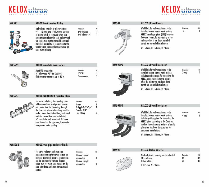
Ball valves; straight or elbow version; ¾” (110 mm) and 1” (130mm) section of piping which is removed when heat counter is installed; flat seal male thread for connection to the manifold bar; seal included; possibility of connection to the temperature monitor; brass with non-po-rous metal plating
Dimension PU
3/4“ straight 1 3/4“ elbow 90° 1
KM591 KELOX heat counter fitting
KM592E KELOX manifold accessories
Manifold accessories:½” elbow cap 90° for KM580Ed35 mm thermometer, up to 80°C
Dimension PU 1/2“AG 1 Thermometer 1
For valve radiators; 4 completely rota-table connections; straight-way or cor-ner connection; for threading through the flow and return without any need to make connections in the floor; individual radiator connections can be isolated; ¾” female thread; union nut, ¾” male euro thread on the pipe side; brass with non-porous metal plating
Dimension PU
4-way 1 A-Nipple 1/2“x3/4“ 2 Cone for 3/4“ Euro fitting 2
KM595 KELOX QUATTROX radiator block
For valve radiators with two pipe connections; straight-way or corner con-nection; individual radiator connections can be isolated; ¾” female thread; union nut, ¾” male euro thread on the pipe side; brass with non-porous metal plating
Dimension PU
Double corner connection 1 Double straight connection 1
KM595Z KELOX two pipe radiator block
Wall block for valve radiators; to be installed before plaster work is done; KELOX multilayer pipes (d16) between flow and return; for connecting to the radiator after it has been installed; suited for concealed installations
W: 150 mm, H: 150 mm, D: 70 mm
Dimension PU 16 1
KM547 KELOX UP wall block
KM597P2 KELOX UP wall block set
KM597P4 KELOX UP wall block set
Wall block for valve radiators; to be installed before plaster work is done; includes guiding pipes for threading the KELOX pipes through to the radiator after the plastering has been done; suited for concealed installations
W: 150 mm, H: 150 mm, D: 70 mm
Dimension PU 2-way 1
Wall block for valve radiators; to be installed before plaster work is done; includes guiding pipes for threading the KELOX pipes according to the Quattrox method through to the radiator after the plastering has been done; suited for concealed installations
W: 280 mm, H: 150 mm, D: 70 mm
Dimension PU
4-way 1
Made of plastic; spacing can be adjusted (40 –50 mm)Colour white:L: 115 mm W: 70 mm
Dimension PU
16 10 20 10
KM599 KELOX double rosette
56
m u l t i l a y e r p i p e s y s t e m
57
m u l t i l a y e r p i p e s y s t e m
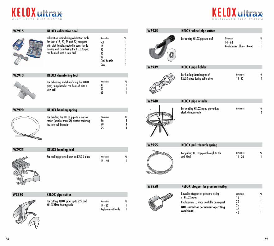
WZ915 KELOX calibration tool
WZ913 KELOX chamfering tool
WZ920 KELOX bending spring
WZ925 KELOX bending tool
Calibration set including calibration tools for sizes d16, 20, 25 and 32; equipped with click handle; packed in case; for de-burring and chamfering the KELOX pipe; can be used with a slow drill
Dimension PU
SET 1 16 1 20 1 25 1 32 1 Click handle 1 Case 1
For deburring and chamfering the KELOX pipe; clamp handle: can be used with a slow drill
Dimension PU 40 1 50 1 63 1
For bending the KELOX pipe to a narrow radius (smaller than 5d) without reducing the internal diameter.
Dimension PU 16 1 20 1 25 1
For making precise bends on KELOX pipes Dimension PU
14 – 40 1
For cutting KELOX pipes up to d25 and KELOX floor heating rails
Dimension PU
14 – 32 1 Replacement blade 1
WZ930 KELOX pipe cutter
WZ935 KELOX wheel pipe cutter
WZ939 KELOX pipe holder
WZ940 KELOX-VerlegehaspelWZ940 KELOX pipe winder
WZ955 KELOX pull-through spring
For cutting KELOX pipes to d63 Dimension PU
14 – 63 1 Replacement blade 14 – 63 1
For holding short lengths of KELOX pipes during calibration
Dimension PU
16–32 1
For winding KELOX pipes; galvanised steel; demountable
Dimension PU
1
For pulling KELOX pipes through to the wall block
Dimension PU
14 –20 1
Reusable stopper for pressure testing of KELOX pipesReplacement O rings available on requestNOT suited for permanent operating conditions !
Dimension PU
16 1 20 1 25 1 32 1 40 1
WZ958 KELOX stopper for pressure testing
58
m u l t i l a y e r p i p e s y s t e m
59
m u l t i l a y e r p i p e s y s t e m
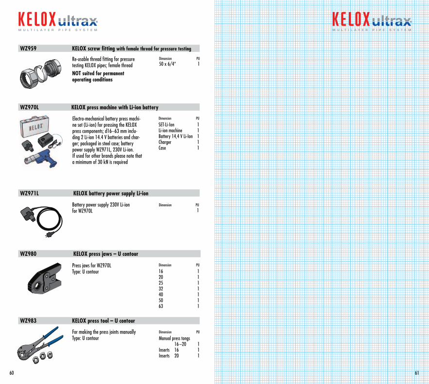
WZ959 KELOX screw fitting with female thread for pressure testing
WZ970L KELOX press machine with Li-ion battery
WZ971L KELOX battery power supply Li-ion
WZ980 KELOX press jaws – U contour
WZ983 KELOX press tool – U contour
Re-usable thread fitting for pressure testing KELOX pipes; female threadNOT suited for permanent operating conditions
Dimension PU 50 x 6/4“ 1
Electro-mechanical battery press machi-ne set (Li-ion) for pressing the KELOX press components; d16–63 mm inclu-ding 2 Li-ion 14.4 V batteries and char-ger; packaged in steel case; battery power supply WZ971L, 230V Li-ion.If used for other brands please note that a minimum of 30 kN is required
Dimension PU
SET-Li-Ion 1 Li-ion machine 1 Battery 14,4 V Li-Ion 1 Charger 1 Case 1
Battery power supply 230V Li-ion for WZ970L
Dimension PU 1
Press jaws for WZ970LType: U contour
Dimension PU
16 1 20 1 25 1 32 1 40 1 50 1 63 1
For making the press joints manuallyType: U contour
Dimension PU
Manual press tongs 16 –20 1 Inserts 16 1 Inserts 20 1
60
m u l t i l a y e r p i p e s y s t e m
61
m u l t i l a y e r p i p e s y s t e m
The technical contents in this brochure are for your information and consultation. We are not liable for thecontents. The application and installation of the products should be adapted to the individual requirements of each project. KE KELIT is constantly improving its products a nd retains the right to make technical changes in the course of these improvements. We are not liable for printing and spelling errors. KELOX 10/10 engl.
62 63
KE KELIT KunststoffwerkGesellschaft m.b.H.
Ignaz-Mayer-Straße 17A-4020 LinzAustria – Europe
Tel. +43 (0)5 0779 Fax +43 (0)5 0779 118
Please note that for technical printingreasons the numbers are written accordingto the common practice in the German speaking countries (i.e. the number and the decimals are separated by a comma).
Full technical back-up and support for theKELOX ULTRAX-Multilayer pipe system is provided by KE KELIT-Austria/Europe.
The network of sales partners, subsidiariesand agents is constantly being expanded.Please ask at the Austrian headquartersfor the current status.

KE KELITKunststoffwerk GesmbH. A-4020 Linz, Ignaz-Mayer-Straße 17 Austria – Europe
Tel. +43 (0)5 0779 Fax +43 (0)5 0779 118
[email protected] www.kekelit.com
Zertifiziertes Qualitätssicherungssystem
durch ÖQS ÖNORM EN ISO 9001:2000
Reg.Nr.366/0
��������
����������������������������
�������� �������������
Mitglied österreichischer
ArbeitskreisKUNSTSTOFFROHR
RECYCLING
ARA-Lizenz Nr.9087
m u l t i l a y e r p i p e s y s t e m