The MSB Journal - Model Ship...
26
The MSB Journal Volume I Issue XII In This Issue -The Matthew Project - Part 6 - Wood Applications Reference Chart - 21 Gun Salute
Transcript of The MSB Journal - Model Ship...

The MSB Journal
Volume I Issue XII
In This Issue-The Matthew Project - Part 6 - Wood Applications Reference Chart - 21 Gun Salute

The MSB JournalISSN 1913-6943
Volume I, Issue XII
February 2008
© www.modelshipbuilder.com
All articles published inThe MSB Journal
are covered under internationalcopyright laws.
This newsletter may be re-distributed freely as long as itremains, whole, intact and un-altered. We also urge you to
print a copy for your workshopor reading area.
Published bywww.modelshipbuilder.com
Front CoverPhoto
The Sea WitchAuraVaughn Raven
How to Contact The MSB Journal
By email:[email protected]
By Snail-MailModelShipBuilder.comc/o Winston Scoville
5 St. Charles Place RR 5Clinton, Ontario, N0M 1L0
Canada
Article / ContentContributions
Please submit all article andcontent contributions to:
In This Issue
Editors Notes
..................................................................3
The Matthew Project - Part 6
..................................................................7
Twenty-One Gun Salute
..................................................................4
Ship Replicas
..................................................................24
From the Files of Ship Wreck Central
..................................................................6
Crossword
................................................................16
Contributors Pictures
................................................................20
What Ship Is This?
................................................................17
Wood Applications Reference Chart
................................................................18
USS Syren Project
.................................................................19
On The Cover
..................................................................25

3
www.modelshipbuilder.com
Volume I Issue XII
Editors Notes
Well, better late than never! :-) Sorry forthe delay in getting this issue out. It’sbeen one of those months.
Some great stuff in this issue. We’re car-rying on with the Matthew Project andthings are starting to shape up prettyquickly now. We all know “Murphy’s Law”.Well it’s played havoc with our timelineplans for the Matthew Project and wewere hoping to have it wrapped up bynow. Suffice to say, it will be another
little while. Not to worry though, within the next couple of months we shouldhave it wrapped up. We’re hoping by the April issue to be able to let you knowabout the Plans (POB & POF) and their status as they should be completebythen. As well we should be able to provide you info on the Kit. If you areinterested in purchasing any of these and haven’t already let me know be sureto contact me so I can add you to our growing list. Send an email [email protected] letting me know which items you are inter-ested in. Once I have the details, I will contact you personally to let you knowpricing etc. and you will be given first choice on our initial runs of each. Re-member, the more people that are interested up front the better! It helps keepthe cost down.
Remember! We’re always looking for interesting articles, pictures etc for thejournal. So, if you have something you’d like to submit, just email it [email protected].
And don’t forget,while you are at the site to visit a few of our sponsors links tohelp keep the Journal free! It only takes a second and you never know whatyou’ll find! :-)
Okay, that’s it from here. Happy reading!!!!!
Winston Scovillewww.modelshipbuilder.com
A Naval Display at Pioneer Villagein London Ontario Canada this past
summer at a War of 1812 event.

4
www.modelshipbuilder.com
Volume I Issue XII
The Twenty-One Gun Saluteby Gene Bodnar
warriors, gun salutes were given as a demonstration of peaceful intentions,because while guns or cannons were being fired harmlessly, it rendered thoseguns ineffective. Frequently, the firing was maintained almost incessantly, thuscreating a huge wastage of gunpowder.
By 1730, the Royal Navy issued orders for 21-gun salutes for certain anniver-sary dates, and in the later eighteenth century, it became mandatory as a sa-lute to the Royal family.
The first official salute by a foreign nation to the United States occurred onFebruary 14, 1778, when Captain John Paul Jones fired 13 guns to the Frenchfleet anchored in Quiberon Bay, France, and received 9 in return.
Why 21 guns? First of all, odd numbers were superstitiously considered to belucky. For example, 7-gun salutes were once popular because the numberseven was believed to hold mystical powers. Another reason may originatefrom the fact that the United States Navy, in 1818, prescribed the specificmethod of rendering a 21-gun salute, and the Union contained 21 states whenthose regulations were formulated.
For most nations today, the 21-gun salute is used to honor only the most im-portant dignitaries. Today, the U. S. Navy only allows such salutes to be firedby ships and stations designated by the Secretary of the Navy, and then onlyfor Washington’s birthday, Memorial Day, Independence Day, to honor thePresident, and to honor heads of foreign states. Furthermore, with the ap-proval of the Secretary of the Navy, naval officers may be given salutes onsignificant occasions, but the number of guns is reduced to 17 for an Admiral,15 for a Vice Admiral, 13 for a Rear Admiral (upper half), and 11 for a RearAdmiral (lower half) – always at five second intervals and always an oddnumber.
Many folks claim that the 21-gunsalute originated as a tribute to theAmerican Revolution, but this isnot so. The main purpose of limit-ing the gun salute to 21 guns wasto cut costs and save gunpowder.Long before the American Revolu-tion, even back to the days of early

5
www.modelshipbuilder.com
Volume I Issue XII
AnatAnatAnatAnatAnatomomomomomy of a Shipy of a Shipy of a Shipy of a Shipy of a Ship
Looking for that special bookto help with your modeling
subject?
Check out these Anatomy ofa Ship series of books and
more at theModel Ship Builder Amazon
Store.
Take advantage of greatprices and free shipping!
Model Ship Builder Amazon Storewww.modelshipbuilder.com

6
www.modelshipbuilder.com
Volume I Issue XII
turn set fire to the CAPRICIEUX. All three vessels weredestroyed in the enormous fire as they drifted acrossthe harbour, guns spontaneously shooting off in theheat. The fire destroyed over half the remainingFrench fleet in Louisbourg. The defenders were demor-alized. The besiegers, although encouraged, were alsomoved by the inferno. "To humanity, altho an enemy,the scene was very shocking," wrote a British officer.The large number of wrecks which fell victim to the
From the Files of ShipWreck Cenral
CELEBRE was a French warship of 64 gunscommanded by De Marolle in 1758. She wasbuilt in Brest.
British cannon fire struck the poop of theCELEBRE during the siege of Louisbourg andset off some cartridges.The fire caught hermizzen mast, and the small number of menaboard were unable to put it out. Sparks fromthe fire set fire to the ENTREPRENANT which in
Typical Profile
siege at Louisbourg make underwater identification difficult. Which one of themany wrecks in Louisbourg Harbour was CELEBRE? Careful archaeology byParks Canada provided the answer. A bronze tube was the key to identifying thewreck of CELEBRE. Called "the working barrel" it was part of a hollow tubewhich allowed water to be pumped out of the "bilges" (the bottom of the ship).Different French shipyards used different barrel lengths. This particular lengthwas used on vessels made at Brest. Because CELEBRE was the only sunkenwarship at Louisbourg built at Brest, a positive identification could be made.CELEBRE's wreck is protected from the open ocean by Louisbourg's harbourand is well preserved. It is also close to the Fortress Louisbourg National His-toric Site which has made it easier to protect from souvenir hunters. The wreckhas been carefully documented and a limited number of artifacts have beentaken up for study. The wreck is open to supervised recreational diving bookedthrough licensed tour operators at Louisbourg. Its rows of cannons and moundsof recognizable artifacts make it a popular international diving attraction.
Dive the wreck at www.shipwreckcentral.com

7
www.modelshipbuilder.com
Volume I Issue XII
The Matthew Project - Part 6
The Garboard
The garboard plank is the first plank to install on the hull. It is a speciallyshaped plank with ends called hoods. Looking at fig.1 above you can see theplank is narrow in the center and tapers outward toward the ends, which isexactly opposite of the side planking, which are wider in the middle and taperto about half their width at the ends.
In the photos below (fig.2 and fig.3) are the hood ends of the garboard. Theyellow arrow is the garboard and the orange and red arrows point to the endsof the bottom planks. Notice the planks at the top of the photo are much nar-rower than the three bottom planks.
fig.1
fig.2 fig.3

8
www.modelshipbuilder.com
Volume I Issue XII
The best way of making the garboard is to first create a template. Making apattern of the garboard starts with a 3/8 wide strip of cardboard. It is clampedat the sternpost (fig.4). When the strip takes its natural bend it will tend tomove away from the keel (fig.5).
If you were to pace the strip against the keel, the ends of the pattern willsweep upward leaving a gap between the plank and the keel (fig.6).
If you were to clamp the end at the sternpost and keel then force the patternalong the keel, a kink in the plank will accrue (fig.7).
The objective is the get the garboard to naturally lay flat against the bulkheadsand along the keel to the stem and sternpost. The only way this can be done isto cut the garboard to shape. The easiest way is trial and error, or trim till it fitsmethod.
fig.6 fig.7
fig.4 fig.5

9
www.modelshipbuilder.com
Volume I Issue XII
In order to shape the garboard start inthe center of the plank and cut off atapered sliver about an inch from thestem and again from center to thesternpost. Your cutting more off fromthe center of the plank than at theends. It may take a little touch up atthe ends to get a nice fit in the rabbit.When the garboard is cut to the cor-rect shape it will lay flat without anykinks or forcing the plank. You can seein the photos (fig.8 & 9) the kink isnow gone and the garboard plank layssmooth and flat.
Once you have a garboard plank thatfits use it as a pattern for the otherside of the hull. You may have to goback and trim the bottoms of thebulkheads if the garboard does notslip into the rabbit with a nice tightfit. The garboard is easy to glue inplace because the rabbit will hold it.The only clamping will be at the ends.
fig.8
fig.9
In ship building there is a term “spiling”what it means is cutting a plank toshape. Hull planking is not just a matterof tapering the ends of a plank. Eachand every plank has its own uniqueshape. Some planks will flare at theends then narrow and widen thennarrow again.
Spiling is a method of taking measurements from a batten which is first laid onthe hull so it forms a smooth run. When the batten is set, measurements arethen taken along its length (fig.10). These measurements are transferred to aplank and a line is drawn from one measurement to the next forming the bot-tom of the plank.
fig.10
10
www.modelshipbuilder.com
Volume I Issue XII
fig.11
fig.12
fig.13
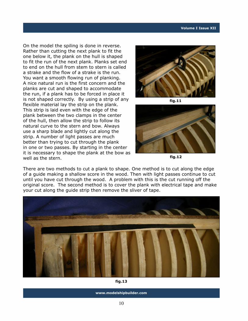
On the model the spiling is done in reverse.Rather than cutting the next plank to fit theone below it, the plank on the hull is shapedto fit the run of the next plank. Planks set endto end on the hull from stem to stern is calleda strake and the flow of a strake is the run.You want a smooth flowing run of planking.A nice natural run is the first concern and theplanks are cut and shaped to accommodatethe run, if a plank has to be forced in place itis not shaped correctly. By using a strip of anyflexible material lay the strip on the plank.This strip is laid even with the edge of theplank between the two clamps in the centerof the hull, then allow the strip to follow itsnatural curve to the stern and bow. Alwaysuse a sharp blade and lightly cut along thestrip. A number of light passes are muchbetter than trying to cut through the plankin one or two passes. By starting in the centerit is necessary to shape the plank at the bow aswell as the stern.
There are two methods to cut a plank to shape. One method is to cut along the edgeof a guide making a shallow score in the wood. Then with light passes continue to cutuntil you have cut through the wood. A problem with this is the cut running off theoriginal score. The second method is to cover the plank with electrical tape and makeyour cut along the guide strip then remove the sliver of tape.

11
www.modelshipbuilder.com
Volume I Issue XII
This method may take a little practice but works very well once you get thehang of it. What is being done here is taking off slivers of wood until you reachthe black tape. A key to success is the direction you cut, in one direction youget short cuts because you are cutting against the grain, in the opposite direc-tion you cutting with the grain and you can slice off long slivers of wood. Eitherway you choose to shape your plank the final step is to run a sanding blockalong the edge to smooth it out. Use a small sled with the sandpaper doubletaped to the side, it will take just a couple passes to even out the edge.
When your finished with shaping the plank a final check is done to see if thenext plank will lay flat to the bulkheads and tight to the plank on the hull.
fig.16 fig.17
fig.14 fig.15

12
www.modelshipbuilder.com
Volume I Issue XII
As each plank is cut to fit watchwhere they end up in relation to themarks you placed on the bulkheadswhen you lined off the hull. Thesecond bottom plank will end upvery close to the mark. If you aretoo far off further up the hull youwill need to take drastic measuresto insure all the planks will fit.
fig.18
It takes a lot of clamps to secure the plank to the hull (see fig’s 19-21). Somebuilders will use a 5 minute Epoxy or a fast setting supper glue. I have hadplanks spring loose when the Epoxy lets go, so I found the use of Titebondwood glue to work the best, however it does require clamping the planks untilthe glue sets. In the following series of photos different methods of clampingare shown. The orange tip clamp is clamped to the bulkhead and presses theplank down and inward. By using C clamps and a small scrap of wood theplanks are clamped to each other. The black tipped clamp at the bow pinchesthe tip of the plank into the rabbit. The large spring clamps pull the plank to-ward the keel and tight against the garboard plank.
fig.19

13
www.modelshipbuilder.com
Volume I Issue XII
fig.19 fig.20 fig.21
fig.22
It is not all the crucial to set every plank perfectly even with the previousplank. If there is a little bump in the planking it can be sanded out. The bluearrows are point to areas where the planking is slightly raised. Planking used onthis hull is thick enough to enable sanding to smooth everything out.
fig.23 fig.24

14
www.modelshipbuilder.com
Volume I Issue XII
After the first bottom plank is set in place the shaping process is repeated sameas was done with the garboard and the second bottom plank is glued in place.From a view of the bow and stern the height of planking should match at thestem and sternpost.
fig.25 fig.26
John Cabot and The Matthew
For more information about The Matthew and John Cabotvisit the Model Ship Builder Website.
www.modelshipbuilder.com

15
www.modelshipbuilder.com
Volume I Issue XII
After the bottom planking is in place the first wale is in-stalled. The wales are higher than the planking so it iseasier to finish the planking before the wale is installed.Finishing can be done by hand or with a sanding disk onthe Dremel. Once again a sanding disk is made to suitethe job at hand. A soft felt disk is cut out and a 180 gritsandpaper is stuck to the felt with double sided maskingtape. Because there are convex and concave areas on thebottom planking a soft disk is used to prevent the edgesof the disk from digging into the planking. The disk willconform nicly to the shape of the hull.
Before and after photos show the difference between theplanking as installed and after a sanding with a 180 gritsanding disk. All the bumps and glue are sanded awayleaving a smooth surface. At this point you can continuewith finer sandpaper or stop at the 180 grit sandpaperdepending on how fine you want the finish.
fig.27
In part 7 the first wale is installed and the side planking will be completed.
fig.28 fig.29

16
www.modelshipbuilder.com
Volume I Issue XII
Anchors Aweigh by Gene Bodnar
Across1 Three-sheaved device fitted to a crane, used in catting an anchor3 Triangular flat face forming the holding surface of an anchor’s
fluke5 To hoist the fluke of an anchor upwards after it has been catted in
preparation for stowing it on the anchor bed7 Sail or canvas attached to a spar used as a drogue9 Triangular flattened barb at the end of an anchor arm, which digs
into the ground11 Contraption connected to a line and cast overboard in order to
slow a vessel down or hold her head to the sea in bad weather12 Small anchor used to anchor a small boat17 Device near the stem of a ship that is rung during fog21 No Clue22 Turning an anchor around by the stock so that it gets into proper
position for stowing on the anchor bed24 Small short-linked chain or rope used to hold fast the stock of an
anchor after it has been hoisted to the billboard25 Shaft forming the principal part of an anchor, connecting the
anchor ring to the arms26 Heavy device connecting a chain cable to an anchor27 To hoist an anchor by its ring so that it hangs there ready either
for letting go or for bringing inboard28 Small device used to mark the position of an anchor when it is on
the bottom29 Part of the anchor where the arms are joined at the shank30 Triangular board fixed to an anchor fluke to increase its holding
ability in soft ground31 Rough piece of wood used as an anchor buoy
Down1 Device used to hoist the anchor from the
waterline up to the billboard2 Extremity of the palm of an anchor3 Another name for the bill of an anchor4 Rope forming the tackle with which the
anchor is hove up from the water’ssurface to the bow
6 Crosspiece fitted at the top of ananchor’s shank at right angles to theplane of the arms
8 Short cable stopper used to temporarilysecure a rope or cable
9 Device used to hoist the fluke end of astocked anchor to the billboard
10 Light anchor used to keep a ship steady13 Device used for inserting the hook into
the balancing band of the anchor in orderto hoist the anchor
14Short length of chain with a pelican hook,used to hold the anchor to the billboard
15 Short rope used to secure an anchor tothe billboard when stowed
16 Device with a shackle fitted off thecenter of gravity of a stocked anchor sothat it will be horizontal when hoisted
18 Two protuberances on the upper part ofan anchor’s shank
19 No Clue20 Device located at right angles to the
fore-and-aft line at either end of thevessel
23 Heaviest anchor of a ship25 Upper part of the anchor shank, bearing
the stock and the anchor ring

17
www.modelshipbuilder.com
Volume I Issue XII
On March 20th 1922 theUSS Langley was commis-sion in Norwalk Virginia.She was the first aircraftcarrer and had been con-verted from a collier.
Surprisingly only 5 people were able to determine last months mystery ship:The USS Langley
What Ship Is This?

18
www.modelshipbuilder.com
Volume I Issue XII
Wood Application Reference Chart
Been wondering what woods you can use for various applications on yourscratch build or as a replacement in your kit? The following chart is a quickreference chart you can use when planning your projects.
Planking and decks: Apple, basswood, box, cherry, elm, gum,holly, larch, maple, pear, sycamore, and tupelo.
Frames: Apple, ash, basswood, birch, box, cherry, degame, elm,holly, maple, pear, and tupelo.
Bent frames: Apple, ash, basswood, box, elm, holly, and tupelo.
Masts and yards: Birch, box, degame, pear, pine, spruce, andteak.
Deck equipment: Apple, basswood, box, cherry, holly, maple,pear, sycamore, and tupelo.
Blocks and deadeyes: Apple, beech, box, cocobolo, holly, lig-num vitae, and pear.
Solid hulls: Bass, cedar, jelutong, pine (sugar and white), pop-lar, and tupelo.
Deck houses: Apple, basswood, birch, box, cherry, gum, maple,mahogany, pear, poplar, tupelo, and walnut.
Treenails: Apple, bamboo, birch, box, cherry, holly, maple, andpear.
Carving: Apple, box, cherry, dogwood, holly, jelutong, degame,pear, persimmon, tupelo, and whitebeam.
Turning: Apple, box, cherry, dogwood, holly, pear, maple, satin-wood, and whitebeam.
Extract from Gene Larsons Shop Notes

19
www.modelshipbuilder.com
Volume I Issue XII
USS SyrenThis could be your next project!
Have you been looking for your next modeling project? Perhaps you’d like to tryyour hand at scratch building. If so, here is a project I’m sure you will thor-oughly enjoy. The USS brig Syren by Chuck Passaro.
This project has been ongoing now for a number of months over at the ModelShip World discussion forum. At present there are approximately 150 membersregistered for the build with some 45 of them with an online build log whereyou can follow along with their progress.
To register for the build, merely drop by and register at Model Ship World(www.modelshipworld.com if you are notalready a member of the site). Once in theForum area for the Syren build be sure torequest to be added to the members listfor the build. There is a thread/post set upspecifically for new member requests.Once you have been authorized you willthen have complete access to all the plansrequired for the build as well as Chuck’sextensive Practicum for the build.
Be sure to start a build log there as well. It’s a great place to display yourprogress as well as get some constructive input from everyone on your build.
This is a great build with a very active group of builders!Be sure to check it out!
www.modelshipworld.com

20
www.modelshipbuilder.com
Volume I Issue XII
Contributors Pictures
Here’s a little update from Mike Pendlebury on his self-righting lifeboat project.
The outer layer of planking is laid diagonally andeach plank had to be steamed before gluing inplace.
After sanding downand coating with
sanding sealer theposition of the bilge
keels were plotted andafter they were
laminated they wereglued in position on
the hull.
To the right is the planking laid beforesanding.

21
www.modelshipbuilder.com
Volume I Issue XII
The next stage was to fit the rubbing strakearound the hull level with the top of thebulwarks. As this has to curve in two planes atonce it was laminated from smaller sectionswith the final capping being model aircrafthard balsa leading edge moulding!
Whilst waiting for the glue to dry during theplanking phase ( took me two weeks tofinish!!!!!!!) I constructed the rudder for the boat.This slides up and down on a square shaft toprevent damage when launching down the
slipway.

22
www.modelshipbuilder.com
Volume I Issue XII
Ship Model Discussion Forums
Looking for a place to share information with other modelers? Maybe you’re stuckon something and need to ask a question or two of another modeler. Don’t have amodeling club in your area?
Be sure to check out all the online discussion forums for model builders. Whetheryou are building tall ships or ships from the steel navy, there’s a discussion forumout there for you.
Check the Model Ship Builder website’s Links page for a growing list of activemodeling forums.
Know of a good forum that is not listed? Let us know so we can add it to the list.
Next are some update pictures sent in by Jim Watts on his refurbishing of aHydroplane. Previous pictures can be seen in Issue VII.

23
www.modelshipbuilder.com
Volume I Issue XII
And last but certainly not least are some pictures of a model under constructionby Jacques Fontaine of Pintendre, Quebec, Canada. So far Jacques has about1350 hours into the build of this 75” long model which he started in 2005.

24
www.modelshipbuilder.com
Volume I Issue XII
Ship Replicas
The Pride of Baltimore II
Commissioned in 1988 is asailing memorial to the origi-nal Pride of Baltimore, whichwas tragically sunk by a whitesquall off Puerto Rico in 1986.She is a replica of 1812-era
topsail schooners called Balti-more Clippers.
Viking Ship ReplicaThis one is an old Replica, on display at the Chicago World Fair in 1893.

25
www.modelshipbuilder.com
Volume I Issue XII
On The Cover
On the cover this issue is The Sea Witch as built by Aura Vaughn Raven.
The Sea Witch was one of the earliest and most famous clipper ships, built in1846, New York. Designed for quick passage the clipper ships sleek hulls knifedthrough the oceans at record breaking speeds laden with perishable cargoes.
Acres of sail caught the wind and drove some of the clippers faster than manyof the steam and diesel ships of today.
Sailing her maiden voyage to China from New York she set her first of manyrecords.
You can learn more about this model and the Sea Witch at:
http://thatravenmagic.com/seawitch.html
Be sure to let them know how you found them!

26
www.modelshipbuilder.com
Volume I Issue XII
Anchors Aweigh Answersby Gene Bodnar
Advertise With Us!
Like to advertise in The MSB Journal? Contact us for details!