![Someold and new problems in combinatorial geometry I ... · arXiv:1505.04952v1 [math.CO] 19 May 2015 Someold and new problems in combinatorial geometry I: AroundBorsuk’s problem](https://static.fdocuments.in/doc/165x107/5e973c25e89a7d07482707fe/someold-and-new-problems-in-combinatorial-geometry-i-arxiv150504952v1-mathco.jpg)
THE MORSE CODE v WITH COMBINATORIAL · PDF filev WITH COMBINATORIAL GEOMETRY ... Russian...
169
DNA 2860T SAI-72-511-LT ?Afy 1972 THE MORSE CODE v WITH COMBINATORIAL GEOMETRY TOPICAL REPORT 1 January 1971 through 28 February 1972 by E. A. Straker W. H. Scott, Jr. N.R. Byrn -HEADQUARTERS Defense Nuclear Agency JK Washington, D.C. 20305 - 12 1, Contract DASA01-71-C-0044 Approved for public release; distribution unlimited. SCIENCE APPLICATIONS, INCORPORATED P. 0. Box 2351, 1250 Prospect St., La Jolla, Calif. 92037 (714) 459-0211 •. Reproduced by NATIONAL TECHNICAL. INFORMATION SERVICE SprIngfield, Va. 22151
-
Upload
vuongtuong -
Category
Documents
-
view
223 -
download
2
Transcript of THE MORSE CODE v WITH COMBINATORIAL · PDF filev WITH COMBINATORIAL GEOMETRY ... Russian...

DNA 2860TSAI-72-511-LT
?Afy 1972
THE MORSE CODE
v WITH COMBINATORIAL GEOMETRY
TOPICAL REPORT
1 January 1971 through 28 February 1972
by
E. A. StrakerW. H. Scott, Jr.
N.R. Byrn
-HEADQUARTERS
Defense Nuclear Agency JKWashington, D.C. 20305 - 12 1,
Contract DASA01-71-C-0044
Approved for public release; distribution unlimited.
SCIENCE APPLICATIONS, INCORPORATED
P. 0. Box 2351, 1250 Prospect St., La Jolla, Calif. 92037 (714) 459-0211•. Reproduced by
NATIONAL TECHNICAL.INFORMATION SERVICE
SprIngfield, Va. 22151
UNCLASSIFIEDSecurity Clasujficatinn
DOCUMENT COTROL DATA.- R At D(SONmwdty Classification of title. boo of obetmct end indorning Iarotaltic. must be onfoe#. when Mhe owwfol; report is cfassiIled)
I ORIGINA TING ACTIVITY (COOPemtS at~OSU0) 28. REPORT SECURITY CLASSIFICAI $ON
Science Applications, n.Ucasfe _____
P. 0. Box 2351, 1250 Prospect Street 2b. GROUP
La Jolla, California 920373 REPORT TITLE
THE MORSE CODE WITH COMBINATORIAL GEOMETRY
4 OESCRgP TIVE NOTES (Tpe of repare And inchuelvo dotes)
Topical Re ort, 1 January 1971 through 28 February 19725 AU TIOR4Iu) (First nest. agtddle initial. feet eeaso)
Edward A. Straker, William H. Scott, Jr. , N. Rick Byrn
6 REPOAT DATE 7a. TOTAL NO OF PAGES 176. No OF REps
May 1972 186 1 21"O. C ON TRACT OR GIOANT NO S.ORIGINATOWS REPORT NUM111RISI1
DASAO 1-71 -C-0044SA-251L
NWERc Task & Subtask XAXPE072 Pb. OTHER REPORT NOMS (Any ohrnuothes R dbteha may be saset*,d
the rep.51)
d. Work Unit 04 DNA 2860T10 DISTRIBUTION STATEMENT
Approved for public release; distribution unlimited.
I I SUPPLEMENTARY NOTES 12S. SPONSORING MILOITARYI AC TIVITY
DirectorDefense Nuclear Agency
________________________ IWashinglon. D.C. 20K~513 BSRAC NThe combinatorial geometry allows efficient Monte Carlo radiation trans -
port calculations of detailed three-dimensional geometries. Because regions andmedia are formed by combination of basic bodies such as boxes, spheres, cylinders
*and others,' the input required of the user is both relatively simple and easily mod-ified. The MORSE code is a multigroup neutron and gamma ray transport MonteCarlo code that may solve either neutron, gamma ray, or coupled neutron-gammaray problemns in either the forward and adjoint mode. A O0JsE has a wida variety ofavailable input options, including splitting, Russian roul~ette, exponential transform,energy biasing, importance regions, albedo surfaces, and the scoring options avail-able in the SAMB0)analysis package.
This document details the incorporation-6f a new version of combinatorialgeometry into the MORSE code and is meant as a user Is manual. All new subrou-tines, including the combinatorial geometry, are documented in defT_-1fTadmgflow charts. Input instructions for all MORSE options and layout,; of all MORSEcommons are given for user reference. The PICTURE code has been modified towork with the combinatorial geometry, allowing two-dimesoa rne itrsocombinatorial geometry models. Two MORSE sample problems and a PICTUREsample problem discussed. Input and output from these problems and the corn-plete code are - isiable from the Radiation Shielding Information Center.
DD ,Nov 54al473 UNCLASSIFIED

UNCLASSIFID"ecwHtY ClAS~iflestion ,
SWOD LINK A LINK 8 LINK:R~O L E WT POL.r WT ROLE[ WT
M0RSE
combinatorial geometry
Monte Carlo radiation transportneutron and gamma raymultigroup cross sections
three-dimensional geometryuser's manual
mm ' IUNCLASSIFIEDUS"Wity C6.6m6ification

ABSTRACT
The combinatorial geometry allows efficient Monte Carloradiation transport calculations of detailed three-dimen-sional geometries. Because regions and media are formedby combination of basic bodies such as boxes, spheres,cylinders and others, the input required of the user is bothrelatively simple and easily modified. The MORSE code isa multigroup neutron and gamma ray transport MonteCarlo code that may solve either neutron, gamma ray, orcoupled neutron-gamma ray problems in either the forwardor adjoint mode. MORSE has a wide variety of availableinput options, including splitting, Russian roulette, expo-nential transform, energy biasing, importance regions,albedo surfaces, and the scoring options available in theSAMB0 analysis package.
This document details the incorporation of a new versionof combinatorial geometry into the MORSE code and ismeant as a user's manual. All new subroutines, includingthe combinatorial geometry, are documented in detail, in-cluding flow charts. Input instructions for all MORSEoptions and layouts of all MORSE commons are given foruser reference. The PICTURE code has been modified towork with the combinatorial geometry, allowing two -dimen-sional printer pictures of combinatorial geometry models.Two MORSE sample problems and a PICTURE sampleproblem are discussed. Input and output from these prob-lems and the complete code are available from theRadiation Shielding Information Center.
Preceding page blank
"iii]

TABLE OF CONTENTS
Page
INTRODUCTION ........................... 1
II. COMBINATORIAL GEOMETRY .................... 5
2.1 Body Types ......................... 5
2.2 Subroutines ......................... 15
2.2.1 Subroutine Gi..................... 15
2.2.2 Subroutine L00KZ .............. 21
2.2.3 Subroutine GG ................. 24
2.2.4 Subroutine GENI ................... 27
2.2.5 Subroutine ALBERT ................ 29
2.2.6 Subroutine PR ................. 31
2.2.7 Subroutine N0RML.............. 33
2.2.8 Subroutine GTVLIN ............... 35
2.2.9 Subroutine JOMIN ............... 37
2.2.10 Subroutine GTVLL .............. 40
2.2.11 Subroutine G0MST ........... 42
2.2.12 Subroutine EUCLID .............. 45
2.2.13 Subroutine ENDRUN ............. 48
I. MODIFICATIONS FOR UNIVAC-1108 ......... 55
3.1 Built-In Fluence Estimators .............. 56
Preceding page blankV
TABLE OF CONTENTS (Cont'd.)
Page
3.2 Collision Density Fluence Estimator .......... 56
3.3 Track Length per Unit Volume Estimator .... 57
IV. THE PICTURE PROGRAM ................... 101
4.1 Program PICTURE ...................... 102
4.2 Subroutine PRINT ....................... 104
4.3 Subroutine MESH ..................... 106
V. MORSE SAMPLE PROBLEMS ................... 109
5.1 Sample Problem Number 1................. 109
5.1.1 Subroutine INSC0R - Sample ProblemNumber I ................... 111
5.1.2 Subroutine RELC0L - Sample ProblemNumber I ................... 113
5.1.3 Subroutine BDRYX - Sample ProblemNumber I ................... 115
5.2 Sample Problem Number 2 ................ 117
5.3 Sample Problem Number 3 ................ 118
APPENDIX A- -ENERGY INDEXING SCHEME ....... 123
APPENDIX B--INPUT INSTRUCTIONS ............. 129
B. 1 MORSE Input Instructions ................. 129B. 2 05R Geometry Input Instructions ............ 138
B. 2.1 Spherical GE0M ................. 138
B. 2.2 Slab GEOM ................... 138
vi
- -- ---------
TABLE OF CONTENTS (Cont'd.)
Page
B. 2.3 Cylindrical GE0M ................ 139
B. 2.4 General GE0M .................... 140
B. 3 Combinatorial Geometry Input Instructions .... 14Y
B. 4 M0RSEC--Cross -Section Module InputInstructions ......................... 152
B. 5 SAMB0 Analysis Input Instructions ......... 156
B. 6 Input to PICTURE ..................... 159
REFERENCES ............................ 163
vi'

--•. . -•, . • s • • - "4 , L •• • • .
LLST OF FIGURES
*Figure Page
1 Examples of combinatorial geometry method ..... 7
2 Use of OR operators ........................ 9
3 Rect-ingular Parallelepiped (RPP) ............. 10
4 Sphere (SPH) ............................ 10
5 Right Circular Cylinder (RCC) ............... 11
6 Right Ellipi~cal Cylinder (REC) ............... 11
7 Truncated Right Angle Cone (TRC) ............ 12
8 Eilipsoid (ELL) .......... .............. 12
9 Right Angle Wedge (WED) .................. 13
10 Box (BOX) ....... .................... 14
11 Arbitrary Polyhedron (ARB) ................. 14
12 General layout of blank common ............. 58
13 Layout of combinatorial geometry data in blankcommon ............................. 59
14 Detailed layout of the FPD-array in blank common . 60
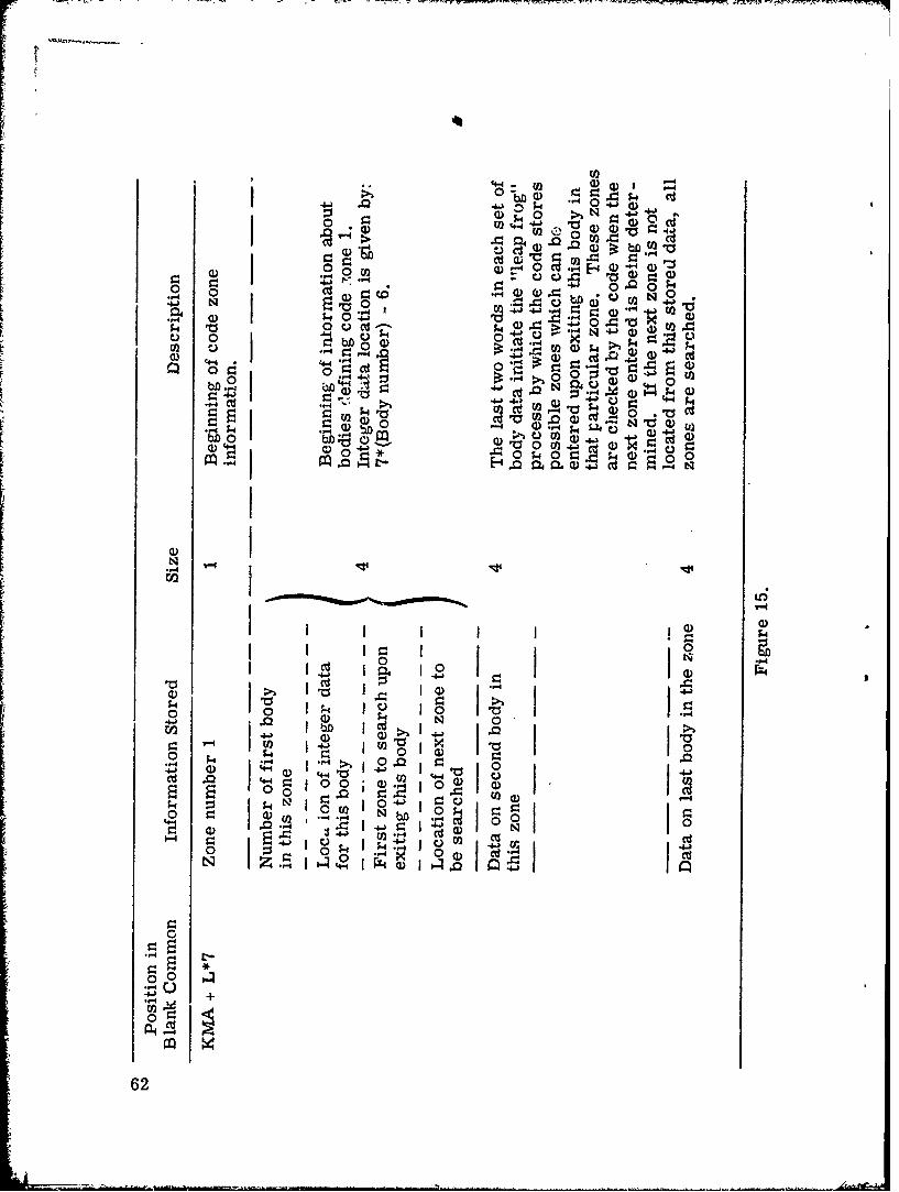
15 Detailed layout of the MA array in blank common .. 63
16 Layout of permanent cross sections in blankcommon .... ........................... 65
17 Layout of particle bank in blank common ........ 66
18 Layout of fission bank in blank common ......... 67
* 19 Layout of user area (analysis) in blank common... 69
ix

LIST OF FIGURES (Cont'd.)
Figure Pag._e
Al Diagram of energy group structure ............ 124
Fx
I.
?I•-.: X

LIST OF TABLES
Table Page
1 MORSE Routines that Depend on Which Geometry
Module is Used ......................... 2
2 Geometry Module Routines .................. 2
3 Indexing of Random Walk Blank Common Arrays .... 70
4 Indexing of Analysis Arrays in Blank Common ..... 73
5 Definition of Variables in APOLLO Common ........ 76
6 Definition of Variables in NUTRIN Common ........ 80
7 Definitions of Variables in USER Common ........ 81
8 Definitions of Variables in Comrnn GOMLOC ..... 82
9 Definitions of Variables in Common L0CSIG ........ 84
10 Definitions of Variables in Common GTSC1.......... 89
11 Definitions of Variables in Common PDET ........ 90
12 Definitions of Variables in Common FISBNK ........ 92
13 Definitions of Variables in Common GE0MC asfound in 05R Geometry ......................... 93
14 Definitions of Variables in Common PAREM asfound in Combinatorial Geometry ................. 94
15 Definitions of Variables in Common 0RGI .......... 96
16 Definitions of Random Walk Variables in BlankCommon .............................. 97
17 Definition of Variables in Common PICT ......... 108
18 Comparison of Results of Sample Problem 1 ....... 110
xi
LIST OF TABLES (Ccat'd.)
Table Page
19 Results of Last Flight Estimator Sample Problem. 117
20 Output from PICTURE Sample Problem ........ 119
Al Numerical Examples for Various Options withCorresponding Energies Given for Each Case .... 125
A2 Values of NQT1, NQT2, and NQT3 for SeveralCases .............................. 127
B1 Sample Group Input Numbers for SomeRepresentative Problems ................... 135
B2 BANKR Arguments (NC0LLS) ............... 13cI
B3 05R General Geometry Input Example ......... 145
B4 Input Required on CGB Card lor Each Body Type. 150
xii

I. INTRODUCTION \
The MORSE Monte Carlo code was first distributed(1) in
early 1970 with a'revised version(2' 3) released in the fall of 1970.
There have been several additional features added in the past year.
This report describes the addition of a version of the MAGI developed
combinatorial geometry)'" (CG) to the MORSE code and also serves to
document a version which is operational on the UNIVAC 1108. The
definition of variables in labefled commons, layout of b!ank common
and input data have been collected for easy reference. A description
of the PICTURE program for the combinaitorial geometry package and
descriptions of routines required to solve two sample problems are
included.
The replacement of the 05R geometry module with the CG
module required significant modification of the CG package. These
modifications were required so that the CG rhodule could be added to
MORSE rather than adding MORSE to the CG package. Only those
MORSE routines that have an interface with the geometry package were
changed and all options in MORSE are available with the CG module.
To retain all MORSE options it was, necessary to write several new
routines as part of the CG module.
Features of MORSE which are dependent on the geometry
module include the ability to (1) determineboth the media and an im-
portar :e region given a set of coordinates, (2) to track a particle through
the system including internal voids and surrounded by an external void,
1 (3) determine the number of mean free paths between any two sets of co-
ordinates (one may be in either an internal or an external void), (4)
determine the vector normal to a surface at any point, and (5) permit
particle'-eflection at a boundary without "getting lost." Table I lists
the MORSE. module routines which were modifiqd to permit an interfaceI - 1
1~\
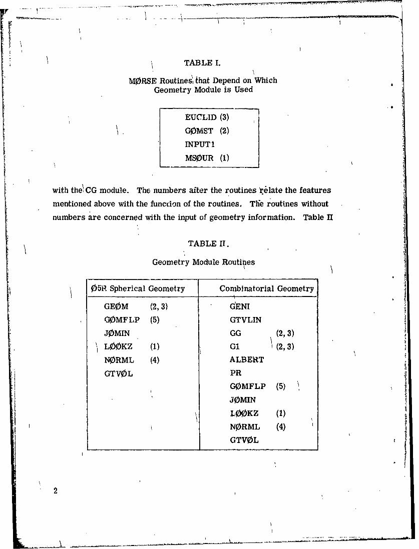
1 TABLE 1.
MORSE Routines, that Depend on WhichGeometry Module is Used
EUCLID (3)
1. G0MST (2)INPUTI
MSLUR (1)
with the! CG module. The numbers after the routines .e'late the features
mentioned above with the function of the routines. The routines without
numbers are concerned with the input of geometry information. Table II
TABLE II.
Geometry Module Routines
05R Spherical Geometry Combinatorial Geometry
GEOM (2,3) GENI
GOMFLP (5) GTVLIN
J0MIN GG (2,3)
SLOKZ (1) GI (2, 3)
NORML (4) ALBERT
GTV0L PR
G0MFLP (5) \J0)MIN
L00KZ (1)
NORML (4) I
GTV0L
2

lists the geometry module routines for the 05R spherical and the com-
binatorial geometry packages.
Only minor changes were made to INPUT and MS0UR and no
additional documentation is provided. INPUT was split into two routines,
INPUTI and INPUT2, to allow a more efficient overlay. Numerous
changes were required for subroutine EUCLID and G0MST and new de-
scriptions and flow charts of these routines are given. A complete
description of the combinatorial geometry package is included and
sample problems are provided.
I
1 3
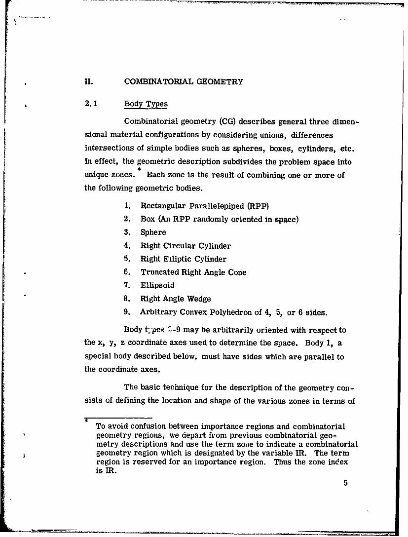
II. COMBINATORIAL GEOMETRY
2.1 Body Types
Combinatorial geometry (CG) describes general three dimen-
sional material configurations by considering unions, differences
intersections of simple bodies such as spheres, boxes, cylinders, etc.
In effect, the geometric description subdivides the problem space into,
unique zones. Each zone is the result of combining one or more of
the following geometric bodies.
1. Rectangular Parallelepiped (RPP)
2. Box (An RPP randomly oriented in space)
3. Sphere
4. Right Circular Cylinder
5. Right Elliptic Cylinder
6. Truncated Right Angle Cone
7. Ellipsoid
8. Right Angle Wedge
9. Arbitrary Convex Polyhedron of 4, 5, or 6 sides.
Body tV pe. ? -9 may be arbitrarily oriented with respect to
the x, y, z coordinate axes used to determine the space. Body 1, a
special body described below, must have sides which are parallel to
the coordinate axes.
The basic technique for the description of the geometry con-
sists of defining the location and shape of the various zones in terms of
To avoid confusion between importance regions and combinatorialgeometry regions, we depart from previous combinatorial geo-metry descriptions and use the term zone to indicate a combinatorialgeometry region which is designated by the variable IR. The termregion is reserved for an importance region. Thus the zone indexis IR.
5

the intersections and unions of the geometric bodies. A special oper-
ator notation involving the symbols (+), (-), and (0R) is used to describe
the intersections and unions. These symbols are used by the program
to construct information relating material descriptions to the body de-
finitions.
If a body appears in a zone description with a (+) operator, it
means that the zone being described is wholly contained in the body. If
a body appears in a zone description with a (-) operator, it means that
the zone being described is wholly outside the body. If the body appears
with an (OR) operator, it means that the zone being described includes
all points in the body. In some instances, a zone may be described in
terms of subzones lumped together by (OR) statements. When (OR)
operators are used there are always two or more of them, and they re-
fer to all body numbers following them, either (j-) or (-).
Techniques for describing a particular geometry are best il-
lustrated by examples. Consider an object composed of a sphere and a
cylinder as shown in Fig. 1. To describe the object, one takes a spher-
ical body (2) penetrated by a cylindrical body (3) (see Fig. 1). If the
materials in the sphere and cylinder are the same, then they can be
considered as one zone, say zone I (Fig. 1c). The description of zone I
would be
I = OR + 20R + 3
This means that a point is in zone I if it is either inside body 2 or inside
body 3.
6 I&

------ -
(a)
(b) (c)
3
(e)
J2K4
I 1I i
Fig. 1. Examples of combinatorial geometry method.
7

If different materials are used in the sphere and cylinder,
then the sphere with a cylindrical hole in it would be given a different
zone number (say J) from that of the cylinder (K).
The description of zone J would be (Fig. Id):
J=+2-3
This means that points in zone J are all those points inside body 2
which are not inside body 3.
The description of zone K is simply (Fig. le):
K=+3
That is, all points in zone K lie inside body 3.
Combinations of more than two bodies and similar zone de-
scriptions could contain a long string of (+), (-), and (OR) operators.
It is important however to remember that every spatial point in the
geometry must be located in one and only one zone.
As a more complicated example of the use of the (OR) operator,
consider the system shown in Fig. 2 consisting of the shaded zone A and
the unshaded zone B. These zones can be described by the two BOX's,
bodies 1 and 3, and the RCC, body 2. The zone description would be
A + 1 + 2and
B= OR+ 3 - 1 OR+ 3 -2
Notice that the OR operator refers to all following body numbers until
the next OR operator is reached.
8

r2B - "-
3 A
Fig. 2. Use of OR operators.
The geometry must be specified by establishing two tables.
The first table describes the type and location of the set of bodies used
in the geometrical description. The second table identifies the physical
zones in terms of these bodies. The input routine processes these
tables to put the data in the form required for ray tracing. Because the
ray tracing routines cannot track across the outermost body, all of the
zones must be within a surrounding external void so that all escaping
particles are absorbed. Also no point may be in more than one zone.
The information required to specify each type of body is as
follows:
a. Rectanguilar Parallelepiped (RPP)
Specify the minimum and maximum values
of the x, y, and z coordinates which bound
the parallelepiped.
9

Ymin ,Ymax
/- -Zmax[ - / -y
Xmi _ Zmin
Xmax.
x
Fig. 3. Rectangular Parallelepiped (RPP).
b) Sphere (SPH)
Specify the vertex V at the center and the scalar,R, denoting the radius.
VRD
Fig. 4. Sphere (SPH).
c) Right Circular Cylinder (RCC)
Specify the vertex V at the center of one base,a height vector, H, expressed in terms of itsx, y, and z compopents, and a scalar, R,denoting the radius.
10

X~Z R
Fig. 5. Right Circular Cylinder (RCC).
d) Right Elliptical Cylinder (REC)
Specify coordinates of the center of the base
ellipse, a height vector, and two vectors in
the plane of the base defining the major and
minor axes. Presently this body is not
implemented.
F
A R2
"V
Fig. 6. Right Elliptical Cylinder (REC).
S~11
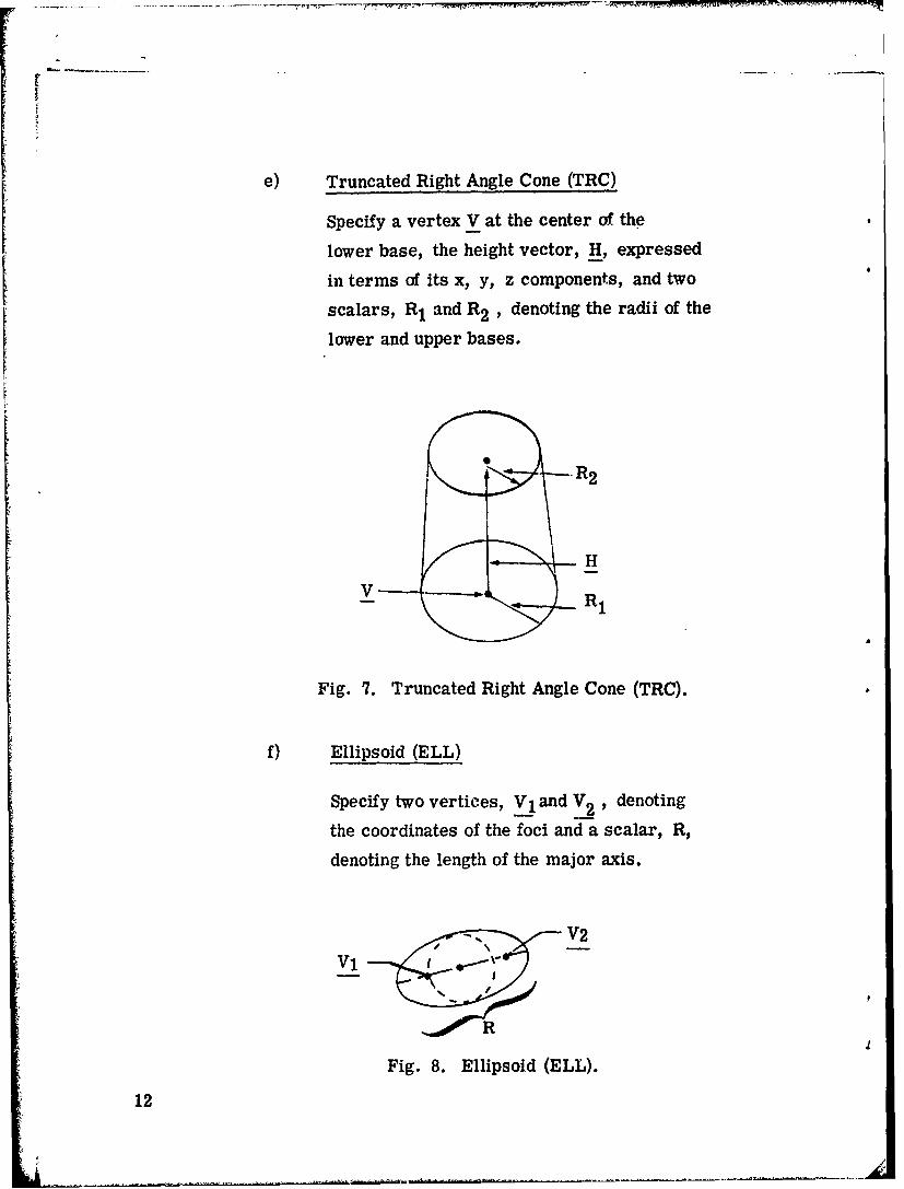
e) Truncated Right Angle Cone (TRC)
Specify a vertex V at the center of the
lower base, the height vector, H, expressed
in terms of its x, y, z components, and two
scalars, R1 and R2 , denoting the radii of the
lower and upper bases.
.~R2
V t R,
Fig. 7. Truncated Right Angle Cone (TRC).
f) Ellipsoid (ELL)
Specify two vertices, V1 and V2 , denoting
the coordinates of the foci and a scalar, R,
denoting the length of the major axis.
V2
Vi
Fig. 8. Ellipsoid (ELL).
12

g) Wedge (WED)
Specify the vertex V at one of the corners
by giving its (x, y, z) coordinates. Specify
a set of three mutually peorpendicular
vectors, ai, with a, and a2 describing the
two legs of the right triangle of the wedge.
That is, the x, y, and z components of the
height, width, and length vectors are
given.
Fig. 9. Right Angle Wedge (WED).
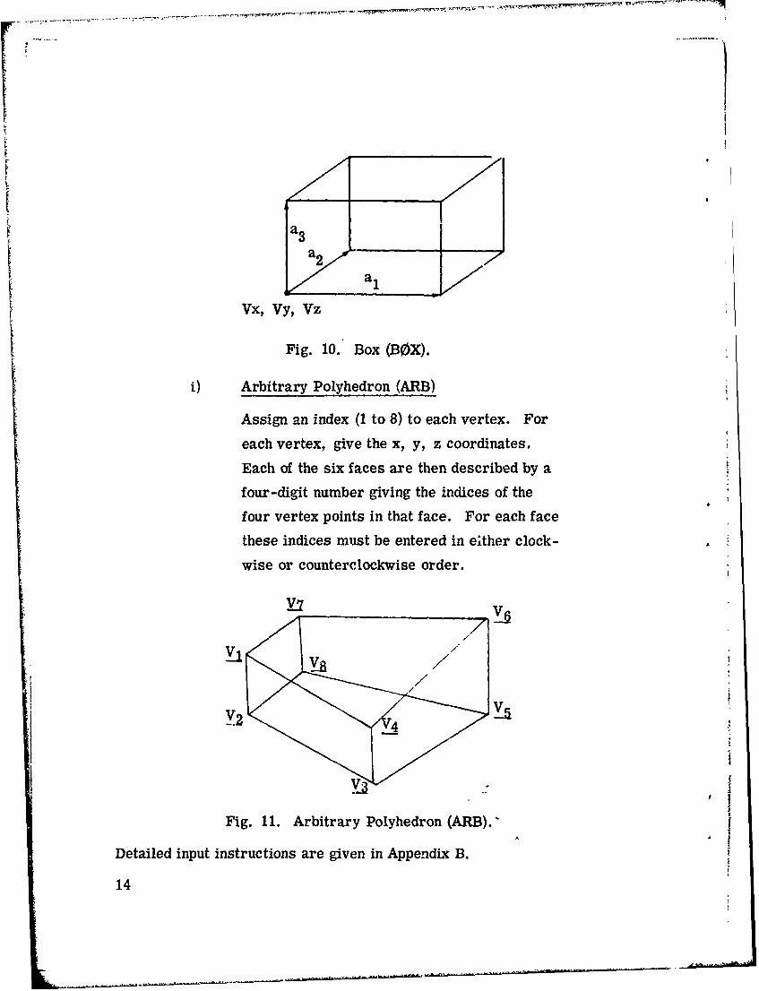
h) Box (BOX)
bpecify the vertex V at one of the corners by
giving its (x, y, z) coordinates. Specify a set
of three mutually perpendicular vectors, al
representing the height, width, and length of
the box, respectively. That is, the x, y,
and z components of the height, width, and
length vectors are given.
13
a3a 2Y al
Fig. 10. Box (BOX).
Si) Arbitrary Polyhedron (ARB)
Assign an index (1 to 8) to each vertex. For
each vertex, give the x, y, z coordinates.
Each of the six faces are then described by a
four-digit number giving the indices of the
four vertex points in that face. For each face
these indices must be entered in either clock-
wise or counterclockwise order.
Y2 4
Fig. 11. Arbitrary Polyhedron (ARB).'
Detailed input instructions are given in Appendix B.
14
2.2 Subroutines
Descriptions of the combinatorial geometry routines are given
with logical flow charts depicting their functions. Two M0RbE routines,
G0MST and L00KZ required significant modifications for use with the
CG package and descriptions of these r:3utines are aLso provided.
2.2.1 Subroutine GI(S, MA, FPD, L0CREG, NUMB0D, IR0R,IRI, 1R2)
G1 is the control routine for the combinatorial geometry. On
one call, it calculates the distance travelled in the present zone, and
the number IR of the next zone to be enteree3 . Essentially GG is called
for each body adjacent to the present zone, calculating RIN and ROUT,
the distances to entry and exit of the body along the trajectcry. The next
zone to be entered is determined by again calling GG to calculate RIN
and ROUT for each body adjacent to the next possible zone. These next
possible zones are determined by examining a list cf all the previous
zones entered on crossing this body. RIN and ROUT are checked against
the input zone descriptions to determine the correct zone. If it is not
found in the list of previous zones, all other zones are examined in a
similar fashion, and when the correct zone is found, it is added to the
list of previous zones for that body. If the new zone is different from
the old, GI returns; otherwise G1 continues tracking until a different
zone is encountered. One change added to the MORSE version of GI is
that if the distance to the next boundary is greater than the distance to
scattering, G1 returns without determining the next zone past the bound-
ary, setting the flag MARKG in common 0RGI.
Called from: G0MST, EUCLID, MESH
Subroutines called: GG
Commons required: PAREM, GOML0C, DBG, 0RGI
15
!1

I\
Variables required:
XB(3) - starting coordinates of present trajectory,
WB(3) - direction cosines of trajectory,
IR - present zone,
DIST - present distance from XB(3),
DISTO "\ distance frbm XB(3) to next scattering point, /
NASC - less than zero if this is a new trajectory,
KL00P - trajectory index,
PINF - machine infinity,
MA, FPD, L0CREG,2 UMB0D, IR0R, tIR1, IR2 - locations in blank common used for variable
dimensioning.
Variables changed:
KL00P - trajectory index incremented if this is 'anew trajectory,
NASC - next body intersected by trajectory,
LSURF -Ii surface of body NASC crossed at next inter-section (negative if leaving and positive ifentering NASC),
DIST - distance from XB(3) to next intersection orcollision site,
MARK set to 1 if distance to collision! (DISTO) isless than distance to next intersection (other-wise 0),
S - disance travelled on this call to G1,
IRPRIM - zone to be entered on boundary crossing,
M•(INEXT) - new zone added to the list of rtext possiblezones for body N1'0,
MA(INEX) - location in MA of next item in the next possiblezone list for body\NB0 (these lists leap-frogthrough the end of the MA array).
16
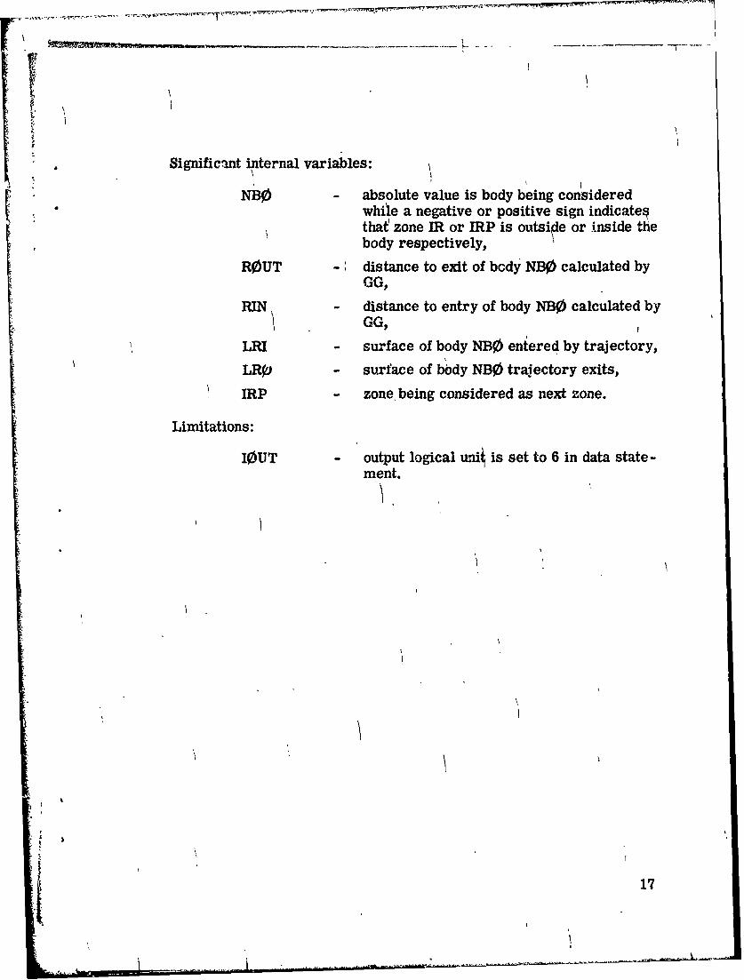
Significant internal variables:
NB0 - absolute value is body being consideredwhile a negative or positive sign indicate§that' zone ER or IRP is outside or Inside thebody respectively,
ROUT - distance to exit of body NB0 calculated by
RIN distance to entry of body NBO calculated byGG,
LRI - surface of body NB0 entered by trajectory,
LRq - surface of body NBO trajectory exits,
IRP - zone. being considered as next zone.
Limitations:
IOUT output logical unit is set to 6 in data state -ment.
17

Subroutine G1 (S, MA, FPD, L0CREG, NUMB0D, IR0R, IR1, IR2)
New trajectory? -Yes Increment trajectoryindex and zero DIST.1
NO
a
Loop over all code p'oduced zone IRR corresponding to input zone IRto find next intersection.
Loop over all bodies defining zone IRR
Call GG
(Is ROUT negatve Yes
Y s- Is NB3 nega tive? 0
No If RIN greater If ROUT greater No-than DIST and than DIST and lessless than SMIN than SMIN
Yes Yes
Set SMIN, NASC, LSURFq Set SMIN, NASC, LSURF-seand ISAVE __and ISAVE
Set DIST and S to either boundary crossing[•MIN, or scattering distanice, DISTO.
If scatterin YYes • A1RRMMARK=1 - ETUR
No
nb
18

Get next possible zone
Is next possible zone YesIRP zero?
No
"" Loop over all bodies NB@ defining zoneIRP to determine if IIRP is next zone.
Call GG
yes-.-- Is NB0 negative ? --- No
tIs ROUT<0or0rT o Not this No Is RI DISTRq)UT <_ DIST N zone Noan
*or RIN > DIST? DISr < ROUT?
Yes Yes
Found againe
d
Set IRPRIM
(If IRPRIM IRý- N o ~
Yes
Move point to next boundarryand be~gin again.
4 19
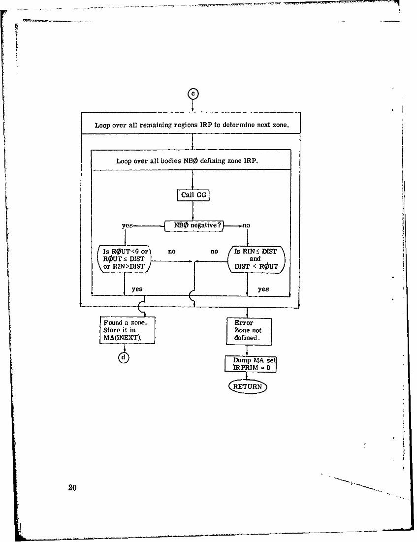
Loop over all remaining regions IRP to determine next zone.
Loop over all bodies NB0 defining zone IRP.
ICall GGI
yes• __ NBO negative? --. no
Is R0UT<O or no no Is RIN SDIST\or RIN >DIST DIS < -- OU.
yes yes
Found a zone. ErrorStore it in Zone notMA(INEXT). Edefined.
Dump MA setEiRPRIM = 0
CRE TU RN
20
i -

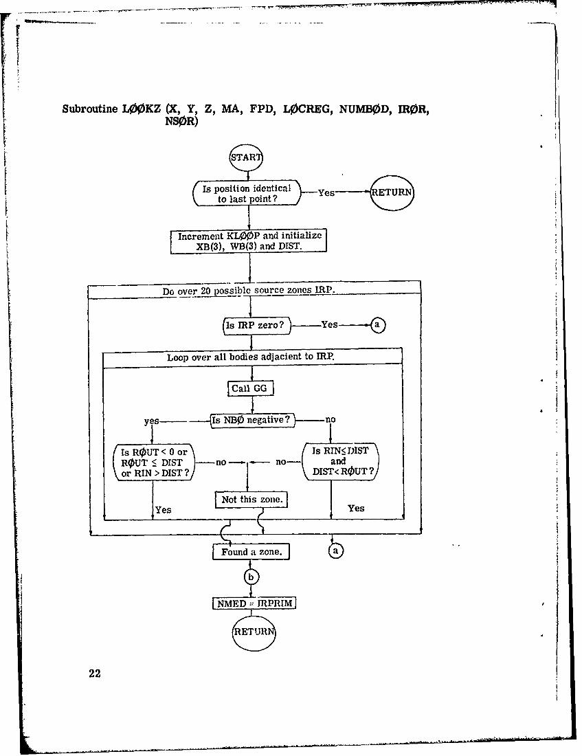
2.2.2 Subroutine L00KZ (X, Y Z, MA, FPD, L0CREG,NUMB0D, IR0R, NSV)R)Z
The purpose of this routine is to return the combinatorial geo-
metry zone of point (X, Y, Z) so that tracking can be initialized. The
coding has been borrowed from the second half of subroutine Gi and
adapted to determine the zone of a source particle. For efficiency
L00KZ builds a list of possible source zones to search on future calls.
If the region is not found on this list, all other zones are examined and
upon determining the new source zone, it too is added to the list. Notice
that the starting direction cosines (. 8, . 6, 0.0) are assumed in L00KZ,
but may be changed elsewhere.
Routines called: GG
Commons required: 0RGI, PAREM, G0MLOC, and DBG.
Variables required:
X, Y, Z - coordinates for which a zone is desired,
MA, FPD, L0CREG, NUMB0D, IR0R, NS0R
- locations in blank common used for variabledimensioning.
Varaibles changed:
KL00P - trajectory index is incremented,
NMED - common 0RGI variable set to correct zonenumber,
NSOR(INEXT) - new zone added to list of possible sourcezones.
Significant internal variables:
WB(3) - set to .8, .6, 0.0 so that L10KZ ne.ed nutbe called with a direction
CG version.
21
F /
Subroutine L00KZ (X, Y, Z, MA, FPD, L0CREG, NUMB0D, IR0R,NS0R)
to last point ? Ye
I Increment KL00P and initializeWB(3) and DIST.
Do over 20 possible source zones IRP.
Is rRP zero? e
Loop over all bodies adjacient to IRP.
Call GOG
yes- IsNOngtv? n
Is ROUT < 0 or Is RIN• DI1STR0UT 5 DIST -no no- andor RIN > DIST ? -DIST< ROUT?
Not this zone.Yes Yes
Found a zone,
22

Save index for adding a zoneto the source list
Loop over all zones IRP.
Loop over all bodies defining zone IRP.
Call GOzI
yes Is NB0 negative ?----- no
-Is ROUTO o-r IsRI DISTR•UT :r DIST }-no-------,..-no- andor RIN >DISTISTr < RUT?
Not this zone
dd it to sourc Write error state-Sment and st]1 NMED 0
23

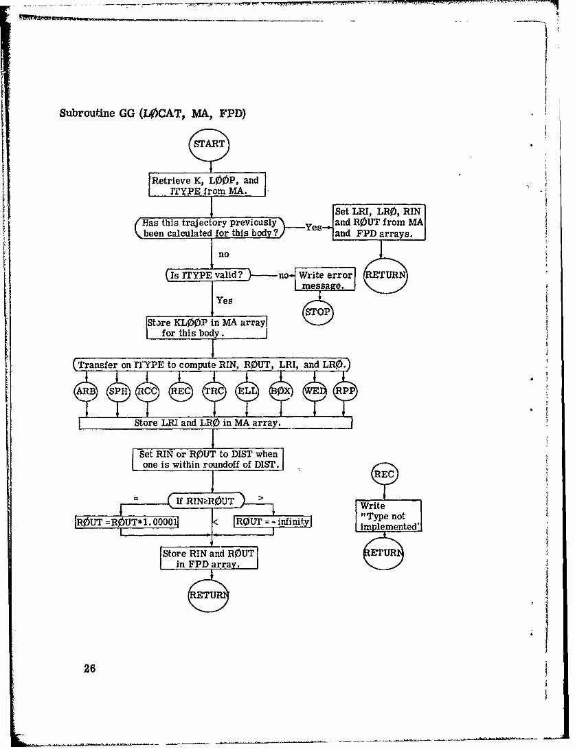
2.2.3 Subroutine GG (L0CAT, MA, FPD)
GG is the workhorse of the combinatorial geometry, comput-
ing distances to intersections for all body types. It is called from GI
or L00KZ to compute distance to entry and distance to exit to a body
whose location in the MA array is flagged by the argument L0CAT. Each
time a distance to entry, RIN, and a distance to exit, ROUT, are calcu-
lated for a body they are stored in the MA array together with LRI and
LR0, the indices of the entry and exit surfaces of the body. Also stored
at this time is KL00P, the particles trajectory index. On a subsequent
call to GG for that body, KL00P is checked against the earlier value,
now LOOP. If they are the same, the old values of RIN, ROUT, LRI,
and LR0 are retrieved so that GG can return immediately.
If it is necessary to compute a new trajectory a different area
of coding is entered for each body type to calculate RIN, ROUT, LRI
and LR0.
Called from: GI and LOKZ
Subroutines called: none
Commons required: PAREM, GEOM2
Variables required:
LOCAT starting locati. n in the MA array of integerdata for the appropriate body,
KL00P - trajectory index,
PINF - machine infinity (stored in RIN and ROUTwhen the trajectory misses the body),
MA, FPD locations in blank common required forvariable dimensioning.
24

Variables changed:
RIN - distance to entrance,
ROUT - distance to exit,
LRI - surface of entrance
LR0 - surface of exit.
Significant internal variables:
L - same as LICAT, starting location in MAarray of body data for the appropriate body,
K - starting location in FPD array of floatingpoint data for the appropriate body.
2
$2
.1
Subroutine GG (L0CAT, MA, FPD)
START
FRetrieve K, LOOP, andrTYPE from MA.
I Set LRI, LR0, RIN{"Has this trajectory previously Yes and ROUT from MAVbeen calculated for this body? and FPD arrays.
no
IsIYEvalid ? no Write error ETURNmessage.1Yes js
Store KL00OP in MA arraylfo tisbody. _j
T(Tanfero YE. to compute RIN, RO)UT, LRI, and LRO..
ARB SPH C RC TRC ELL X RPP
S~Store LRI -and LRO in MA array.
Set RIN or ROUT to DIST whenone is within roundoff of DIST. E
WriteIR0UT =R•UT*1. < lUT =-infini"Type not
Iimplemented'I
Store RIN and ROUT ETURin FPD array.
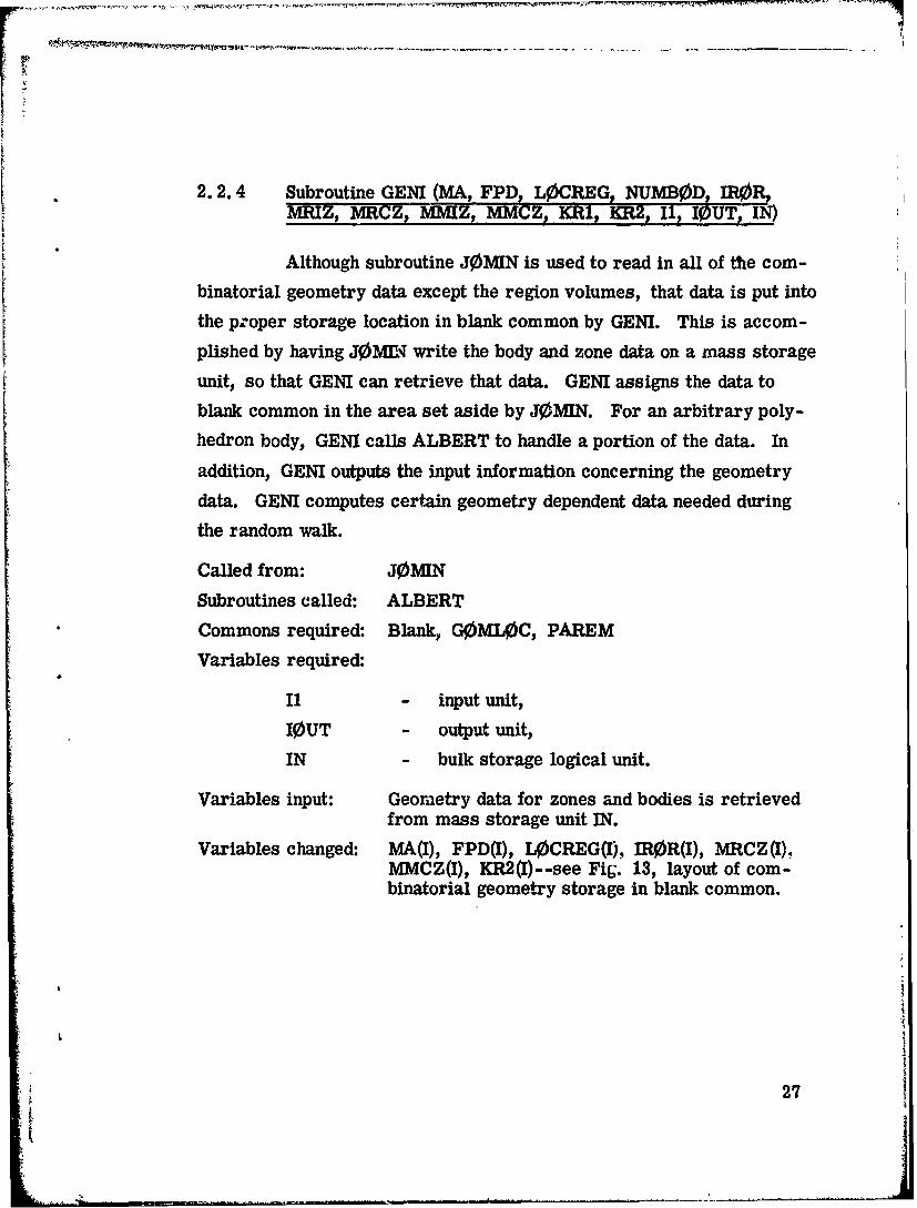
2.2.4 Subroutine GENT (MA, FPD, L0CREG NUMB0D, R9,MRIZ, MRCZ, -MMZ, MMCZ, KR1 KR2, II, I0UT, IN)
Although subroutine J0MIN is used to read in all of the com-binatorial geometry data except the region volumes, that data is put into
the proper storage location in blank common by GENI. This is accom-
plished by having J0MIE write the body and zone data on a mass storage
unit, so that GENI can retrieve that data. GENI assigns the data to
blank common in the area set aside by J0M[N. For an arbitrary poly-
hedron body, GENM calls ALBERT to handle a portion of the data. In
addition, GENI outputs the input information concerning the geometry
data. GENI computes certain geometry dependent data needed during
the random walk.
Called from: J0MIN
Subroutines called: ALBERTCommons required: Blank, G0ML0C, PAREM
Variables required:
I1 - input unit,
I0UT - output unit,
IN - bulk storage logical unit.
Variables input: Geometry data for zones and bodies is retrievedfrom mass storage unit IN.
Variables changed: MA(I), FPD(I), L0CREG(I), IR0R(I), MRCZ(I),MMCZ(I), KR2(I)--see Fig. 13, layout of com-binatorial geometry storage in blank common.
27
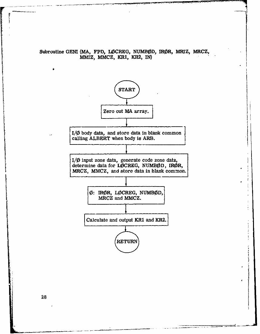
Subroutine GENI (MA, FPD, L0CREG, NUMB0D, IR0R, MRIZ, MRCZ,
MMIZ, MMCZ, KR1, KR2, IN)
START
Zero out MA array.]
1/0 body data, and store data in blank commoncalling ALBERT when body is ARB.
1/0) input zone data, generate code zone data,I ~ ~determine data for LOCREG, NUMBED, IRMRf."
MRCZ, MMCZ, and store data in blank common.
0: ROR, L•)CREG, NUMBED,
MRCZ and MMCZ.
Calculate and output KR1 and KR2.
, 8

2.2.5 Subroutine ALBERT (F, IERR)
ALBERT is called by subroutine GENI to process the arbi-
trary polyhedron (ARB) body data before storage in the FPD array. The
ARB body data as read by GENI consists of the coordinates of all corners
(eight for a six-sided figure), foliowed by a packed decimal number for
each side indicating which corner points make up that side. ALBERT
processes this data, returning a unit normal vector and a minimum
distance to origin for each plane containing a side of the ARB. An ARB
can have up to six sides. These unit vectors and distances then replace
the original ARB data in the FPD array. The number of sides and a
distance that is characteristic of the ARB's minimum dimension are
also stored in the FPD array. This minimum distance is later us(.. for
round-off tests.
Called from: GENI
Subroutines called: none
Commons required: none
Variables required:
F - FPD array read from GENI
Variables changed:
F - FPD array changed to contain unit normalsand distances to origin for each plane. Num-ber of sides and a minimum distance arealso stored.
Significant internal variables:
X(8, 3) - coordinates of cornei points,
IS(6,4) - indicates corners contained in each of thepossible six surfaces,
V(3, 4) - edge vectors for a given surface (an innercross product then gives the normal vector).
29
............

•.~--- ., . -.- r . -+.. -. ;+ q\
Siroutine ALBERT (F, .ERR)
store coordinates of corner p6ints in X(8, 3) and zero F array.J
FCICount the sides, and store cortier indices in IX(6, 4).
" Calculate minimum distance between p__ints.
e rin a calculation for each si~de.]
[Compute two adja cent edge vectors
Compute normal vectors as the cross productsof two adjacent edge vectors.
'compute nMinimum distance to orgin as dot product ofI normal vector and coordinates of the corner.
[Count the number of points on either side of the plane.
(Are all poirts on the far side of the plane?- -Yes
I~hi.~ignof No
\ • go___nofth normalizing factor.
L Normalize normal vectors to unity. Alsodnormalize t! ance by the s~mc factor.
th iS the 1'at._s•ýdj no.. s--! yes
Store normal vxcio-s, distances, minimum side lengtaiand nuntoer of sides in FPD array. *
(RETUIIN
30
4 I

2.2.6 Subroutine PR (Combinatorial Geomery)
Subroutine PR is called from various locations in the combi-Satorial geometry package (GENI, GI, L00KZ and N0RML) wheneverintermediate or debugging output iý required. The amount of geometry
Sdata w hich is output depends on thc value of the argum ent. If this argu-ment is I or 8, all of the geometry data in blank common is printed,
otherwise only selected variables are output. By comparing the argu-ment value given in the output with the s~urce listing, the geometry dataat aý given time in the ýexecution can be determined. The call to PR isinitiated by setting the IDBG variable to a nonzero value' Because ofthe large a•mount of output genrated, this option should not be used dur-ing a normal execution.
Called from: GENI, GI, L00KZ, NORMLSubroutine called: noneCommons required: blank, PAREM, GOMLOC, DBG
I31

Subroutine PR (K
STAkRT
0: K, XB(I), WB(I), IRIR. IRPRIM, NASC, LSURF, LRI, LR0, KL00PI,
LOOP) ITYPE, N, NUJM, L0CAT, ISAVE,
INEXT, IRP,, INEX, LDATA, MUN ROUT, SMUN,
DIST
Is
CK I or
K-=8 No RETURYes
0: G0ML0C ArrayMA Array
FPD ArrayL0CREG, NUMB0D, IR0R, MHIZ, MRCZ, MMIZ,
MMCZ, KRI, KR2, and NS0R Arrays
Lei~2on Volume Array
6RETURN
32
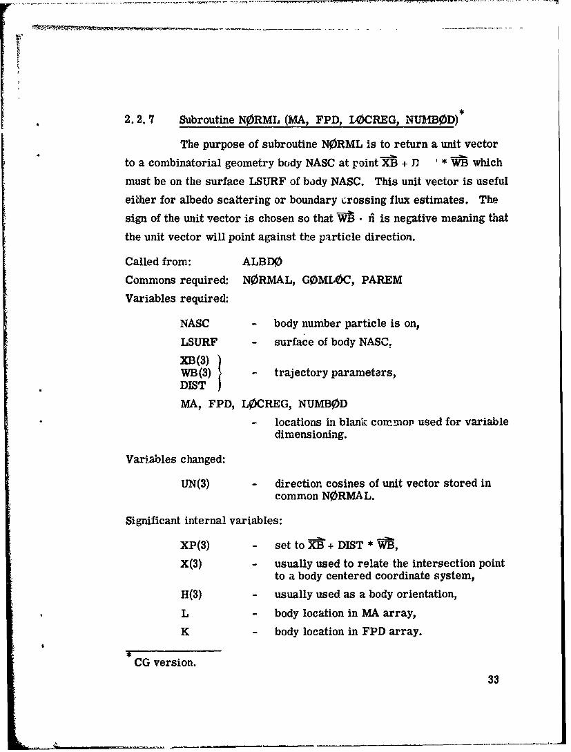
2.2.7 Subroutine N0RML (MA, FPD, 10CREG, NUMB0D)
The purpose of subroutine NORML is to return a unit vector
to a combinatorial geometry body NASC at point XB + J) * WB which
must be on the surface LSURF of body NASC. This unit vector is useful
either for albedo scattering or boundary crossing flux estimates. The
sign of the unit vector is chosen so that W •i^ is negative meaning that
the unit vector will point against the ptrticle direction.
Called from: ALBD0
Commons required: NORMAL, G0MLOC, PAREM
Variables required:
NASC - body number particle is on,
LSURF - surface of body NASC,
XB(3))WB(3) trajectory parameters,DIST I
MA, FPD, L0CREG, NUMBOD
- locations in blank cornmop used for variabledimensioning.
Variables changed:
UN(3) - direction cosines of unit vector stored incommon NORMAL.
Significant internal variables:
XP(3) - set to XB + DIST * WB,
X(3) - usually used to relate the intersection pointto a body centered coordinate system,
H(3) - usually used as a body orientation,
SL - body location in MA array,
K - body location in FPD array.
CG version.33

Subroutine N0RML (MA, FPD,. LOCREG, NUMB0D)
START
LSUR = LSURF, XP XB +DISTWB
: i Determine K, and L, the bodyz• [_locations in the FPD and MA arrays,
Transfer on body type.
AB SPH C EC RCELT 0 RPP
Calculate unit vector
Change sign of unit vector so that fi . WB is negative.
RETURN
Write "Type not imple-mented in NORMAL".
RETUR
34

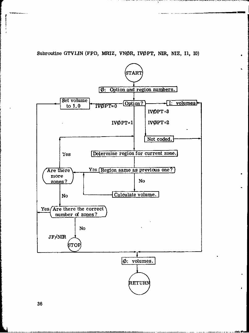
2.2.8 Subroutine r-VLIN (FPD, MRIZ, VN0Rt IV0PT, NIR,
This routine is called by JAMIN to read in or to calculate the
volume of each region in the geometry. The four options available are
(1) to set each volume to 1., (2) to calculate the volumes for concentric
spheres, (3) to calculate the volumes for slabs (not coded at present),
or (4) to read in the volumes for each region from cards. The volumes
are stored in blank common and are only used by the track length and
collision density estimators.
Called from: J0MIN
Subroutines called: none
Commons required: none
Variables required:
FPD - array containing zone description data,
MRIZ - array which relates MORSE region to inputzones,
VN0R - array containing the MORSE volumes,
IV0PT - options for determining volumes,
NIR - number of regions,
NIZ - number of zones,
I1, 10 - input and output logical units.
Variables changed:
Variables in blank common starting at KV0L.
I35
Subroutine GTVLIN (FPD, MRIZ, VN0R, IV0PT, NIR, NIZ, I1, 10)
START
FO: Option and region numbers.
Set volume -- ton? I: volumeto 1.0 _j IVQPT=0
IVjOPT=3
IVOPT=1 IVWPT=2
Not cdd
Yes ILDtermine region for current zone.]
Ire there Y3s Re 'on same as previous one? jmore }zones ? ,/No
No Cacltvoue
Yes(-re there the correctnumber of zones?n
No
JF/NIR I
CTO~P
10: volumes.
ETUR
36
2.2.9 Subroutine JOMIN (NADD, I1, 10)
The input of the geometry data is controlled by the JOMIN
subroutine, which performs the following tasks:
* Reads all geometry input data except the region volumes.
* Writes the body and zone data on a mass storage unit(IOUT=16).
* Determines the length of all geometry arrays.
* Calculates the beginning location in blank common ofgeometry arrays.
* Initializes geometry arrays.
* Calls the GTVIJN subroutine which returns regionvolumes.
Since combinatorial geometry input data is dynamically allocated to con-
serve storage area, it is stored temporarily on a mass storage device.
This allows the core storage requirements to be determined. Hence,
much of the coding in J0MTIN is similar to GENI, which reads the data
on the mass storage device and puts it into blank common.
Called from: INPdT1
Subroutines called: GENI, GTVLIN
Commons required: Blank, GOMLOC, PAREM
Variables required:
All variablem in GOML0C, I1, 10
Variables input:
IVOPT, IDBP, NAZ., MRIZ(I), MMIZ(I)
AVariables changed: A
All variablef in GOMLOC, IVOPT, IDBG, MRIZ(I), MMIZ(I).
* _ _A
CG version.
37
°
Important internal variables:
I0UT - mass storage unit,NAZT - total number of adjacent zones summed over
all zones.
38

Subroutine JOMIN (NADD, II, 10)
START
I Card cGAI
Read body data and write on mass storage.Determine core storage required for FPD and
number of bodies.
Read input zone data and write on mass storage.Determine core storage required for MA and
number of input zones and code zones.
FCalculate starting locations in blank
common of geometry arrays.
II/0: Cards CGD and CGE.
I Call GENT
Calculate number of regions (NIR) and totalstorage required for eometry data (NADD).
zero the NS0R array.
ICall GTVLIN.
RETURN
39

2.2.10 Subroutine GTV0L (MXREG) GN0R)
This routine is called by ENDRUN to calculate the reciprocal
of the volume of each region. It is geometry independenit, since it uses
information determined in GTVLIN.
Called from: ENDRUN
Subroutines called: none
Commons required: G0MLOC, blank
Variables required:
KVOL - index from common GOMLOC,
MXREG - number of regions in the geometry.
Variables changed:
GNOR reciprocal of the volume tor e L: ion.
40
*1I

Subroutine GTV0L (MXREG, GN0R)
41

2.2.11 Subroutine GOMST (TSIG, MARK)
Any boundary crossing between the present and next collision
sites are determined by calling the combinatorial geometry routine G1.
Before the Gi call, combinatorial geometry variables in common PAREM
are initialized, and after the call NUTRON variables are updated.
WATE*S is summed in blank common as a track length flux estimator.
MARK is set to -1 for an external void and -2 for an inte..nal void.
Called from: NXTCOL
Subroutines called: Gi
C'mmons required: NUTRON, APOLL0, PAREM, ORGI, GOMLOC
Variables required:
X, Y, Z, U, V, W, NMED see common NUTR0N for definitions.
BLZNT - value of IR from last track or from L00KZ,
XB(3) - starting coordinates of present trajectory,
WB(3) - trajectory direction cosines,
MAIRK - flag to indicate type of trajectory,
ETATH - distance to be travelled in cm if the flightremains in the same media,
DIST present distance from XB(3).
Variables changed:
X, Y, Z - endpoints of flight,
DISTO - distance from XB(3) to next collision site,
ETAUSD - mean free paths travelled on this call toGOMST,
ETATH - cm travelled on this call to GOMST,
CG version.
42

SMARK flag indicating type of termination of flight,
0 - normal boundary crossing,
1 - flight within one medium,
-1 - particle escaped,
-2 - particle entered an interior void,
NMED andNREG - medium and regioxi of end point,
BLZNT - combinatorial geometry region of end point.
43

I \Subroutine G0MST (TSIG, MARK)
?START
Is this the initial flightY~sof this tr ectory?
S MARK--1No •- •
Initialize combinatoria
geometry variables.
Set end point distance.I
Call 01
Move particle tL X, Y, Z.
i Sumitrack length influx estimator.'
Set ETAUSD, IR, NMED, MARK,NREG, and ETATH.
RETURN
44
V\
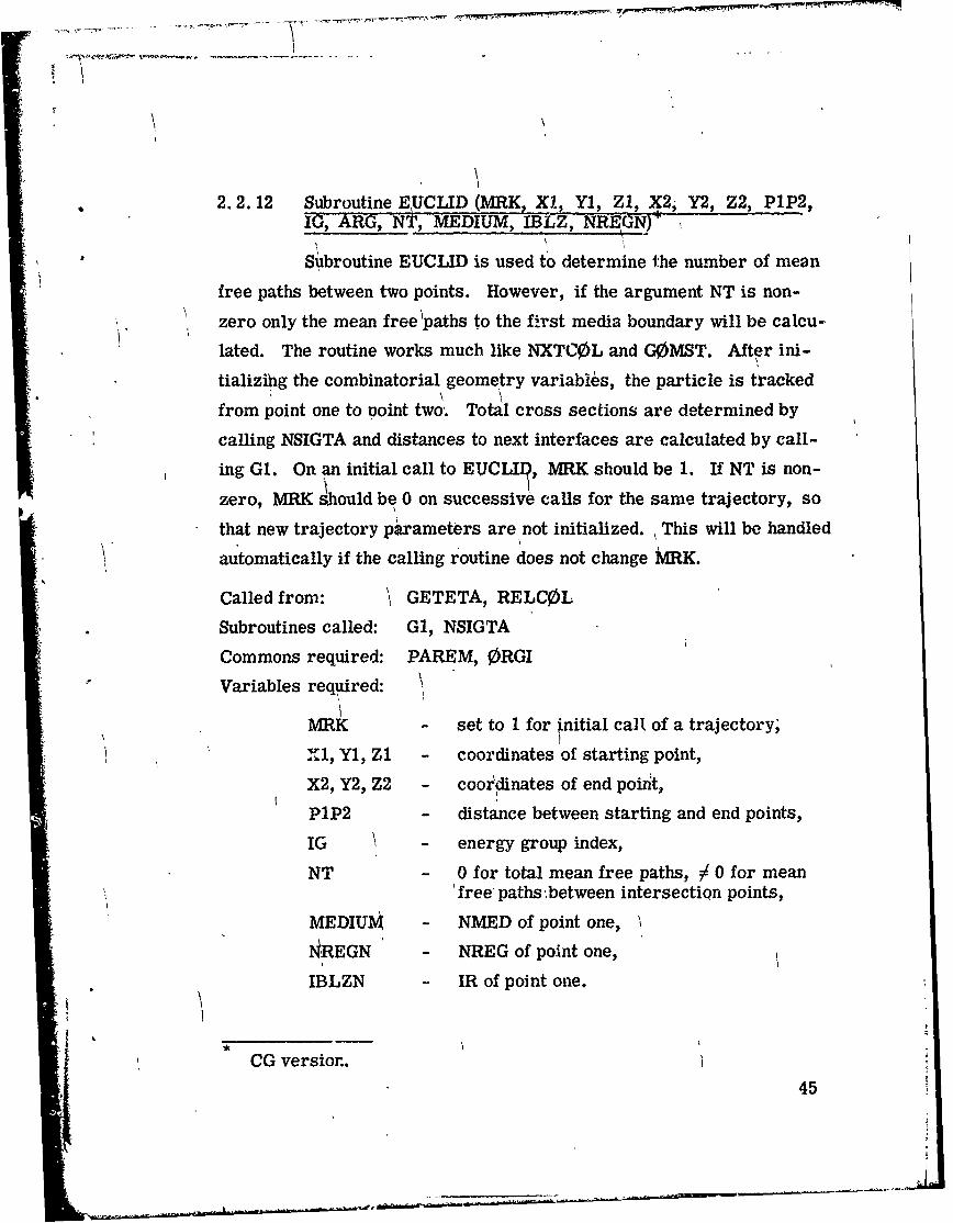
2.2.12 Subroutine EUCLID (MRK, X1, Y1, Z9, x2, Y2, z2, P1P2,IG, ARG, NT, MEDIUM, IBLZ, NREGN)
Subroutine EUCLID is used to determine the number of mean
free paths between two points. However, if the argument NT is non-
zero only the mean free 'paths to the first media boundary will be calcu-
lated. The routine works much like NXTCOL and GOMST. After ini-
tializihg the combinatorial geometry variables, the particle is tracked
from point one to point two,. Total cross sections are determined by
calling NSIGTA and distances to next interfaces are calculated by call-
ing G1. On an initial call to EUCLII•, MRK should be 1. If NT is non-
zero, MRK s.hould be 0 on successive calls for the same trajectory, so
that new trajectory pirameters are not initialized. This will be handled
automatically if the calling routine does not change MRK.
Called from: GETETA, RELCOL
Subroutines called: G1, NSIGTA
Commons required: PAREM, ORGI
Variables required:
MRK - set to 1 for initial call of a trajectory,
Xl, Y1, ZI - coordinates of starting point,
X2, Y2, Z2 - cooliinates of end point,
PlP2 - distance between starting and end points,
IG - energy group index,
NT - 0 for total mean free paths, / 0 for mean'free paths .between intersection points,
MEDIUM - NMED of point one,
NREGN - NREG of point one,
IBLZN - IR of point one.
CG version..
45
Sg** l

Variables changed:
MRK - fora flight reaching the end point,
- 0 for a flight crossing a medium boundary(NT / 0 only),
- -1 for a flight escaping the system,
- -2 for a flight encountering an internal void(NT j/0 only),
X1, Y1. Zi - rF urns boundary intersection point ifNT J0,
ARG - negative of number of mean free paths,NT - if NT / 0 on input, will return as -1 if an
escap3 occurs,
MEDIUM - medium number of end point.
Significant internal variables:
ETA - distance remaining to point two in cm,
ETAUSD - distance travelled on last call of G1.
l4
46

Subroutine EUCLID
STAR
MIf K >O0 No
YYes0
[Initialize combinatorial greometry parameters. I
[ Has 'tal distance been travelled? --Yes- RETURN
ETA ! 0
No
No -Is the medin a void? -- Yesi NME D=1000
Call NSIGTA to get Total cross sectionto-aL cross section. set to zero.
Update media, MARK, mean free pathstravelled Pnd distance remaining.
No If NT 0 - Yes
Set Xl, Y1, Zi to ( If trajectory is completed -N--boundry inrsectio \.or enters external void.
(R:ETUR NYe
RETURN
47oI
, ~47
!IL}-"

I
2.2.13 Subroutine ENDRUN
This subroutine is called at the end of a run. The weight of
the particles at collision and the track length of the particles has been
summed over all collisions within the region for all particles in the run.
Thus, a normalization by the number of particles in the run is required.
In addition, the volume of the region and the total cross section for each
region and energy group is used to determine the average fluence over
the regions for the collision density estimate. For the track length esti-
mate the same coding is used with the total cross section set to 1. Note
that a region cannot contain more than one medium. Since storage al-
locations are flexibly dimensioned, NEX in the SAMBJ3 input must provide
for MXREG + 2 arrays in Blank Common to be used by ENDRUN. A
check is made and if this condition is not met, no output from ENDRUN
is obtained.
There are many manipulations in ENDRUN with the energy
indexes. These manipulations are required in order to treat the six
majci' options in M0RSE. Appendix A gives an example of the six prob-
lems.
Called from: NRUN
Subroutines called: GTV0L, NSIGTA
Commons required: blank, PDET, USER
Variables required:
NMED (REGION) - must be set in data statement,
GN0R - reciprocal of the volume for eachregion,
Many variables in blank common.
48
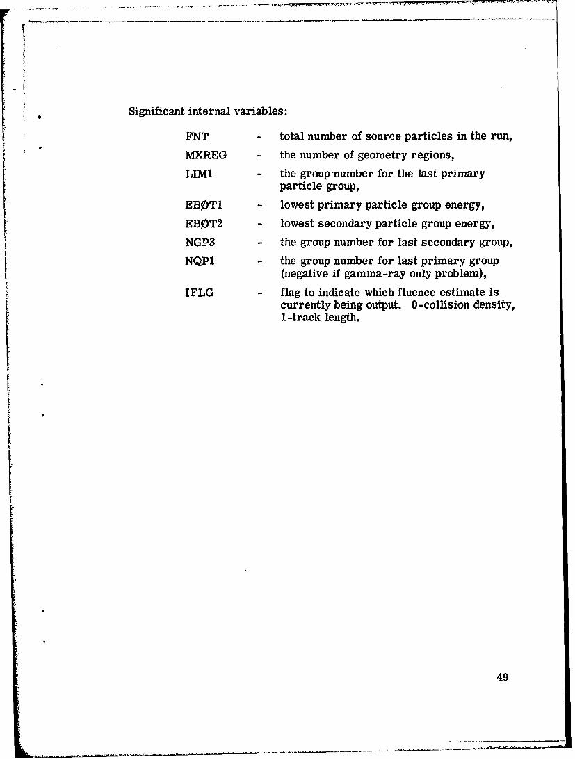
Significant internal variables:
FNT - total number of source particles in the run,
IMXREG - the number of geometry regions,
LIMI - the group number for the last primaryparticle group,
EBOT1 - lowest primary particle group energy,
EBOT2 - lowest secondary particle group energy,
NGP3 - the group number for last secondary group,
NQP1 - the group number for last primary group(negative if gamma-ray only problem),
IFLG - flag to indicate which fluence estimate iscurrently being output. 0-collision density,1-track length.
49
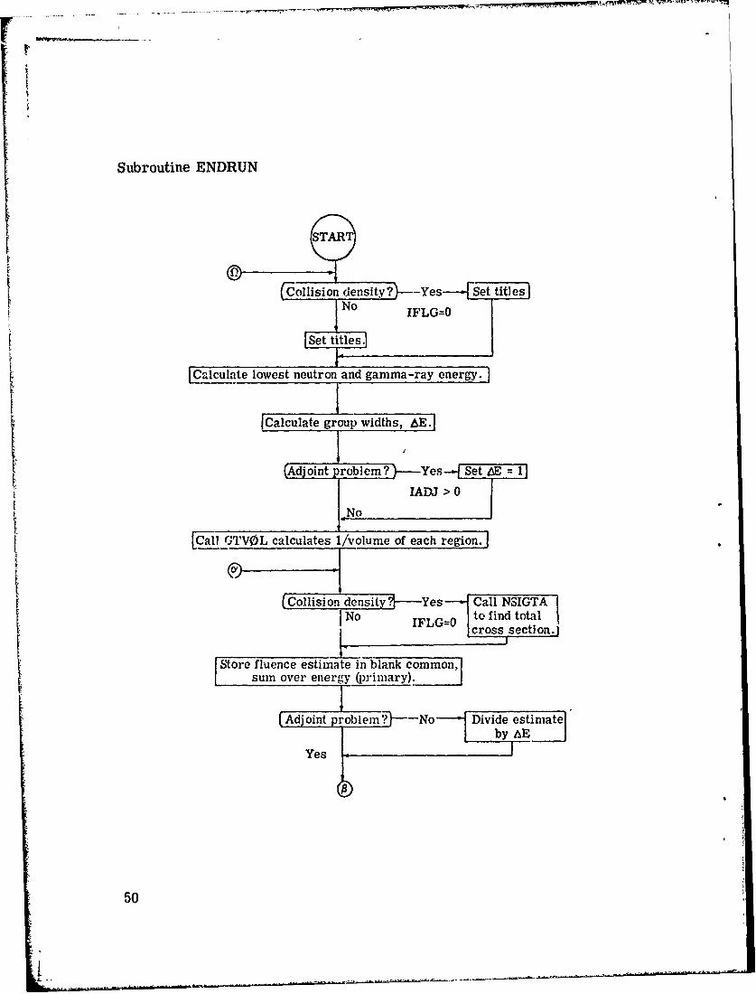
Subroutine ENDRUN
(-Colliision dens-it~y ?----Yes---- e titles
NIFLG=O
iSet tites.I
Calculate lowest neutron and gamma-ray energy.
ICalculiate group widths, &E.
(Adjoint problem? -- Yes Set LE = 1
f IADJ > 0.-No
Call TV0L calculates 1/volume of each region.
Collision density.-Yes Call NSIGTAINo IFLG-O to find totalI cross section.
Store fluence estimate in blank common,sum over energy (primary).
(Adjoint problem?-"--No Divide estimateby AE
Yes
50

I?
Arc treiore primary<NGP particle groups?
No
No- Are there secondary particles?
YesNMTG / NMGP
Call NSIGTA to find total cross section.
Store fluence estimate in blank common,sum over energy (secondary).
(Adjoint pro~b~lem No Divide estimate-_ by AE
YesIADJ > 0
----Yes -- Are there more regions ?
No
' 51

(Adjoint problem Yes 0: Heading
o IAD>0 for table.No-
10: Heading'for table.[
0: Results
ICalculate Eo(E) for each primary group.
No Are there secondary particles?)
YesNGPQTN*NGPQTG > 0
ICalculate E•.(E) for each secondary group.
(,3 group
52

T Yes-- Are there more regions?)
NoNREG> MXREG
NIFLG= INo Has track length estimatorIFLG=O been processed?
R
53
-A

III. MODIFICATIONS FOR UNIVAC-1108
In converting the M0RSE-SAMB0-M0RSEC code fronr che
IBM 360 to the UNIVAC-1108, there were a considerable number of
changes that had to be made. These changes were connected mostly
with the local library functions of the IBM-360 and an attempt was made
to not add local UNIVAC-1108 library functions. The only reduction in
the code's capability is in the diagnostic module where the ability to
look at a bit 3tring and decide whether it was a floating point or integer
number, convert it to hollerith and output it, does not exist in this version.
However, the diagnostic module is mostly machine independent and still
has the capability of writing out values from common and parts of blank
common. Subroutines BNKHLP and HELPER are dummy routines. A
diagnostic routine for the combinatorial geometry package has been added.
Routines which are still machine dependent (involving coding
other than word lengths, data statements and equivalences) are DATE
and TIMER. Subroutine DATE calls ERTRAN and uses DECODE. Sub-
routine TIMER c, IIs CPUTIM that assumes that the time is returned in
units of microseconds.
Subroutine READSG is still machine dependent in its need to
read each card twice and subroutine ERROR has been added--its only
function is to call EXIT. Subroutine INPUT now calls INPUT1 and
INPUT2 with this change, permitting a better use of overlay. The
first six variables in NXTRA from common APOLLO are used.
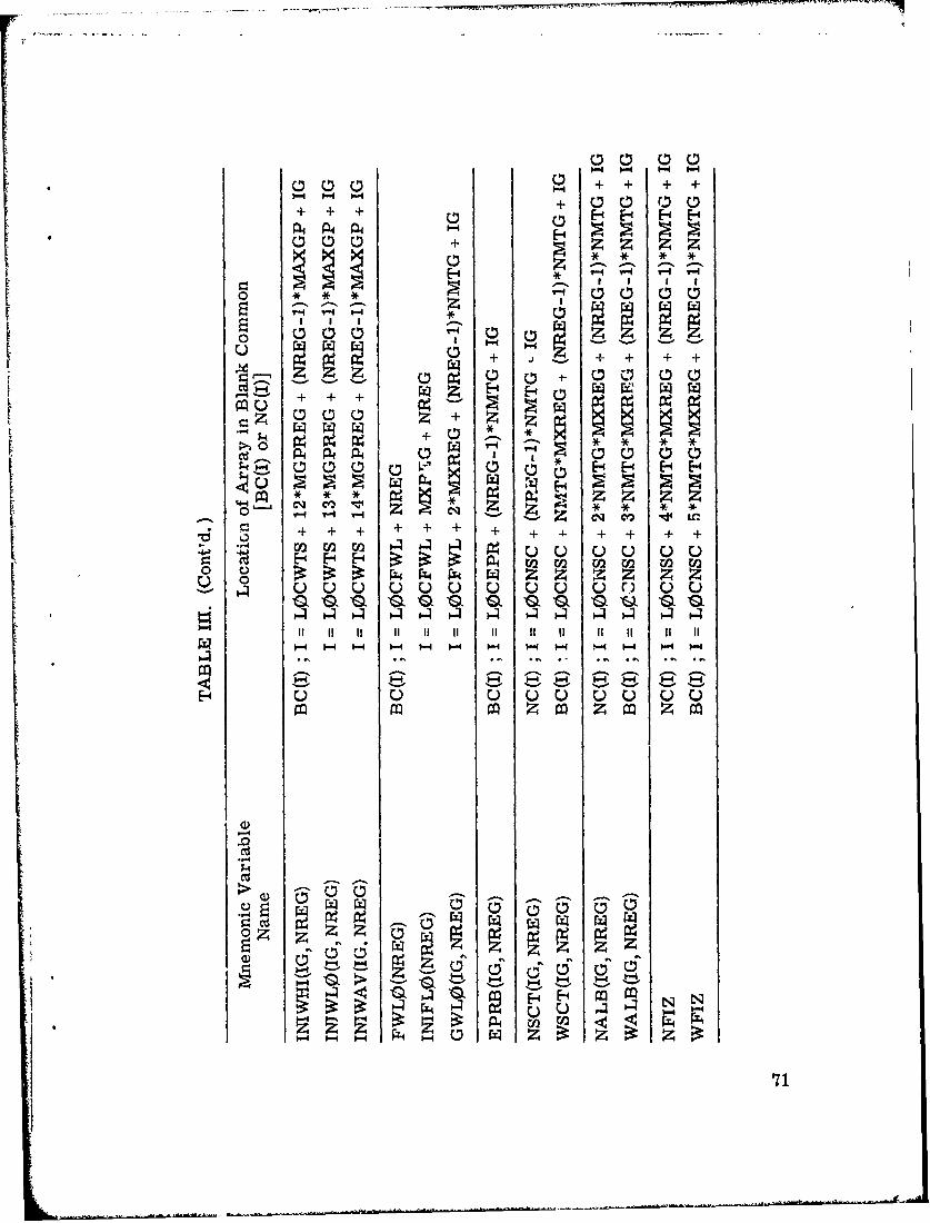
The layout of blank common ir, given in Figs. 12-18 for the
different modules of MORSE. Definitions of variables in blank common
are given in Table III which defines the indexing scheme. Variables in
the labelled commons are defined in Tables IV - XVI.
Preceding page blank
55

A description of the energy indexing scheme in MORSE-
SAMBO-MORSEC is givent in Appendix A.
3.1 Built-In Fluence Estimators
There are two fluence estimators that are "built-in" the
UNIVAC 1108 combinatorial geometry version of MORSE. The addition
of the collision density estimator to MORSE has been discussed pre-
viously 7) and the track length per unit volume estimator has been added
to take advantage of a feature of the combinatorial geometry. The re-
sulting fluence is averaged over geometry regions and if no regions are
used only the spectrum averaged over the whole system is available.
3.2 Collision Density Fluence Estimator
An estimate of the fluence averaged over a region specified
by the geometry input may be obtained from the weight that has been
summed over all collisions in the region by
NVi
F, wS(En=V i NSTRT*NITS*VOL, Tv(Ei)
where
(v(Ei) = fluence in region V at energy E= number of particles of energy E. scatter-
NVi ing in region V,
w = weight of the nth particle of energy E.scattering in region V,
NITS*NSTRT = total number of particles,
VOLV = volume u' region V,
E Tv(Ei) = total cross section for groups E. in region
V.
56

3.3 Track Length per Unit Volume Estimator
Another estimate of the fluence averaged over a region may
be obtained from the track length of the neutron or photon in that region.
The track length calculated by the combinatorial geometry package is
stored in a manner similar to the collision weights. The fluence esti-
mate may be obtained by
NViE L nwn
n=lnnv NSTRT*NITS*VOLV
where
NVi = number of trajectories of energy Ei in region V,
wn = weight of particle on nth trajectory, and
L n = track length of nth trajectory in region V at energyE..1
Subroutine ENDRUN is called to process the weights and
track lengths to obtain estimates of the fluence. In an adjoint problem,
the importance is calculated. The fluence estimate has units of particles/
eV/cm 2/source and in an adjoint problem the units are importance/cm 2
source. The total fluence is integrated over energy from the primary
and secondary energy groups to obtain an integral value for each region.
The only input required for this routine is a data statement giving the
medium number for each region; there is a limitation of only one medium
"--gion. In addition, one of the several options for inputing or calcu-
Lat :' ..be volume of each region must be utilized.
S..The major disadvantage with using these estimators is that
no estimate of statistics is available. The use of this estimator is in-
expensive, however (output routine is called only once), and is meant
to be used as a supplemental estimator.57

SI drtji', MuciCnflO V a~1riable, Length
FS 4*Nhl'rG
CretW04011, 3*M OPREGSt~indards
path MGPPEf',
SPLIT and It. R. 8*MGPREGCOUn1ters ____
L0CFWL ~Initial Wveight 3MPE________Standarosh
Cntirrn 1"W1.0 2*MXTIEGl.0CEPIIz____ GWD NMTG-AIXfEGL0CNS1C__ EPRI3___ NMqTG*MXREG
Scatterivg} ONMMXECount ers____
L0CFSN __NSCA ______ MEDIAFISH ___- NMTG*MEDIA
NGE-O ________ GAIGN NMTG* MEDIAGeome~itry Data See Figs. 13-15 for
_______ _______ details.
NS1GL J'rimmient Cross }See Fig. 16 for details.
Temporary IParticle 14,-NAIOS' see Figz,. 17Cross Bak for deta-ils.
Fission 7'MS FMIT>
NLAST_______ Bankc n-ee Fig. 18 for detai Is.
User Arc., NLEFT see Fig. 19 fordetails.
Fig. 12. General layout of blank Common.
58

WV"-- wa\ "-.- vr~vrr~
, II
Starting ]•iforniation
* Location Size
NGEOM=NADD Length :fM geometry array 1
K ,A MA x
/Integer array , TTIAKFPDD
rPDFloating point array LFPD
KLCRLOCREG
Indices to correlate MA ýrray NUMRKNBD data wi',i code zone data
Number of b6dies for each NU/LRcode zone
KI0RIROR
Indices to correlate input zone NUMRto code zMne
KRIZ AMRIZ
Indices to correlate MORSE IRTRVregion to input zone
KRC' - ____________
MRCZIndices to correlate MORSE NUMRregioon to code zone
KMIZr- NMIZ
Indices to correlate MORSE ' T-media to input zonc R
KMCZNMCZ
Indices to correlate MORSE NUMRmedia to code zone N •
KKR1KR1
Indices to co'relate first code IRTRVzone to "nput zones
,KKR2 K
Indices to correlate last code TRTRV\ ~~zone to input zone !
SINSR -_____ _____
NSORInd,,c. of code zones in which NUMRsource parifcles have bheni found
KVOL -S~VNOR
NGIAST Volume of each MORSF region NIR
Fig. 13. Layout of combinatorial geometry data in bla, common.
59

CIS;-4 I.) 0*4--
4))
-4.
01
w Id
z Z
Cd
4$4
C0)
,T- 44 00
~~- ICd 4w v -ý 0 0
0 bb"z 4:
4-. ,o ~ p4 $4 14p40
rz$4
4ý ::) CIS
600

0~~
0 .4.
U $4
(12(D
$4q
ci)i
N0
Cd 0
a)~~4- IO I I I
0 .0
40 ll00
00 T-4 Cq Cf) Lo co
+ + +I + + + + +
61
a)) S4 0 N.Q: 45 40 0.V.1.0
0 0 U)0Ud() 1
0 O-4a W. hoW Q
-j ci0 ' ) 0
D) I :4
00 Cd00Co+ -
62444 I 4 ,0 0 :

* ~ <~ 'wr."~w. rr' 'r~r~rWO
Cd
.Cd 02 a
00
41
0
* a)
I ) 0 0 (v N 0 gb 0
0 N Q
"-"4
0r-
jj~I -it 6
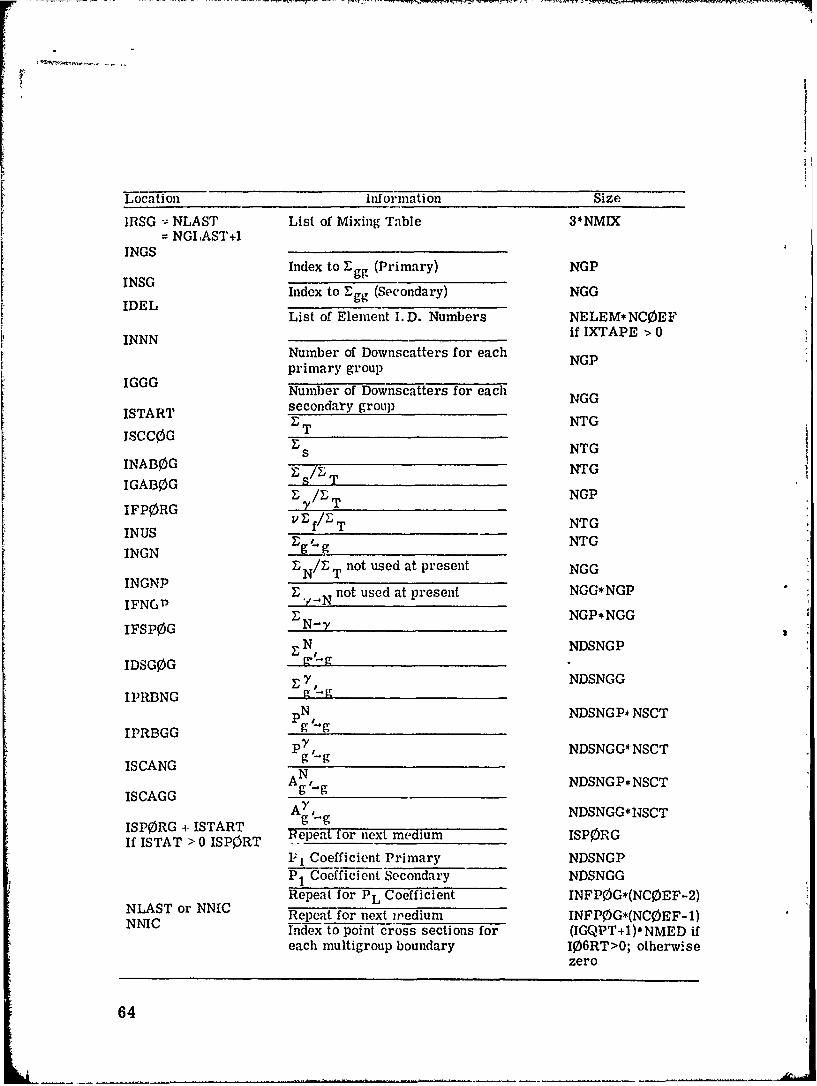
Locntion Information Size
1IRSG = NLAST List of Mixing Table 3*NMIX= NGIAST+I
INGS
INSG Index to Zgg (Primary) NGP
Index to Egg (Secondary) NGGIDEL List of Element I. D. Numbers NELEM*NC0EFINNN _if IXTAPE > 0
Number of Downscatters for eachprimary group
IGGGNumber of Downscatters for each
ISTART secondary groupISCT NTG
Jc0s NTGINAB0G r NTGIGAB0G STZ / NGP
IFP0RG y T
f/ T NTGINUSINGN Eg " 1 g9 - NTG
D /ZT not used at present NGGINGNPIFNGN E.PN not used at present NGG*NGP
ZIFN*NG
IFSP0G N-y NGPNGG
E N INDSNGP
IDSG0GI; 7NDSNGG
IPRBNG g gpN NDSNGP* NSCT
IPRBGG g-gp7 NDSNGG* NSCT
g -.gISCANGg N
ISCAGG Ag ,.g NDSNGP*NSCT
ISP0RG + ISTART g -gIf ISTAT > 0 ISP0RT Repeat for next medium ISP0RG
1-1 Coefficient Primary NDSNGPPI Coefficient Secondary NDSNGGRepeat for PL Coefficient INFPOG*(NC0EF-2)
NLAST or NNIC Repeat for next wedium INFP0G*(NCOEF-1)NNIC Index to point cross sections for (IGQPT+I)*NMED if
each multigroup boundary 106RT>o; otherwisezero
64
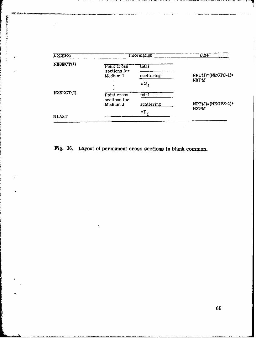
Location Information Size
NXSECT(1) Point cross total
sections forMedium I scattering NPT(1)*(NEGPS-1)*
.~ NXPM
NXSECT(J) Point cross total
sections forMedium J scattering NPT(J)* (NEGPS-1)*
NXPMurfNLAST
Fig. 16. Layout of permanent cross sections in blank common.
65

Location Variable
-;N= NSIGL IG
U
V
w
xY
Variables are fromZ NUTR0N common,
see Table VI forWATEdefinitions.
AGE
BLZNT
NAME
NAMEX
NMED
NREG
NN0 + 14
Repeat for Particle 2
NN0 + 14*NM0ST = NLAST
= NFISBN IF MFISTP > 0
Fig. 17. Layout of particle bank in blank common.
66L'

Location Variable
NFISBN X
y
zWATEF
AGE
IG
NAMEX
NFISBN + 7
Repeat for particle 2
NFISBN + 7*NM0ST = NLAST
Fig. 18. Layuut of fission bank in blank common.
67
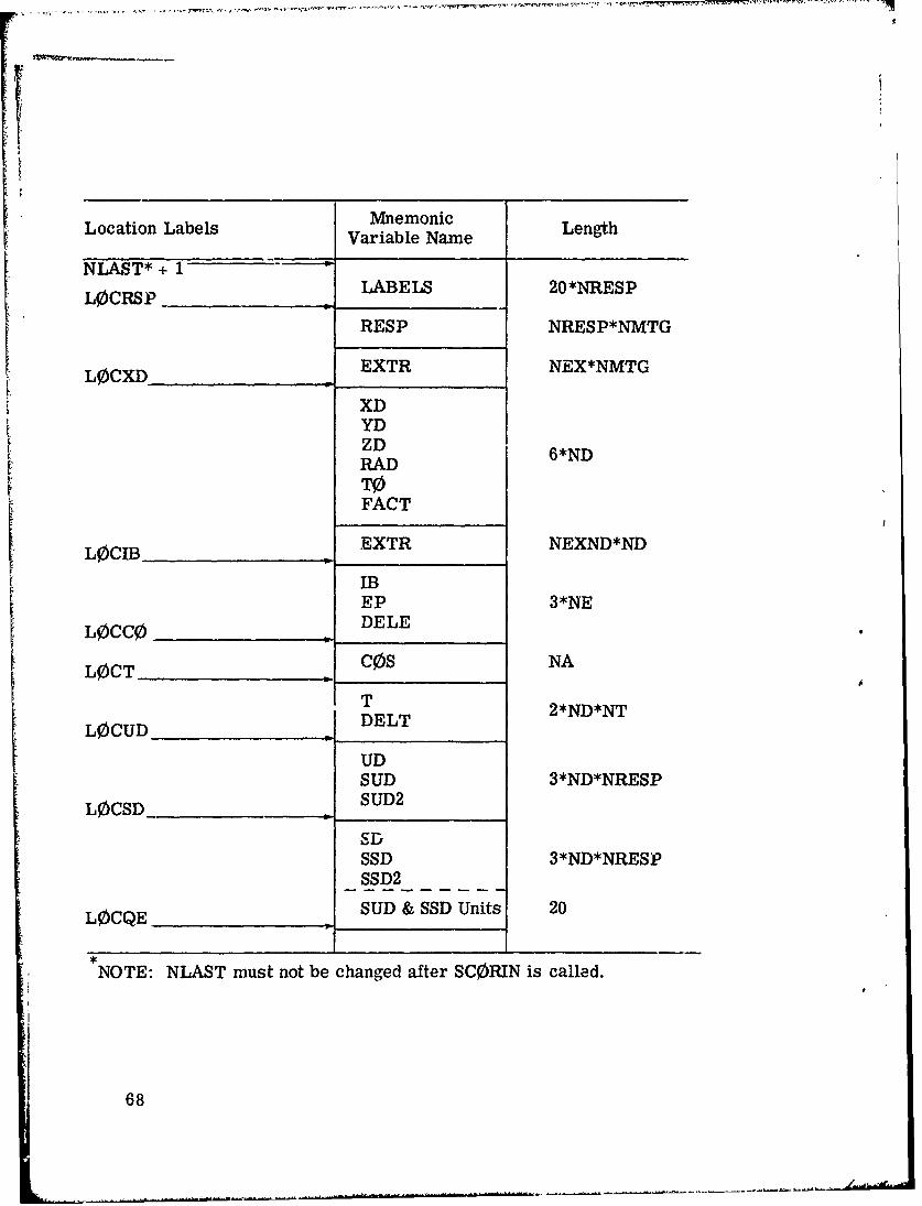
Location LabelsMnemonic LntLocation LabelsVariable Name Lnt
NLAST* + I
L0CRSP -___LABELS 20*NRESP
RESP NRESP*NMTG
L0CXD___O_____ EXTR NEX*NMTG
XDYD
ZD 6NRAD 6N
T0FACT
EXTR NEXND*ND
_____ ____ ____ DELE 3N
L0CT__Cos____NA_
L0CU DET 2*ND*NT
UD
SUD 3*ND*NRESP
L0CSD__----------- SUD2
SD
SSD 3*ND*NRESP
SSD2_
L0CQE SUD & SSD Units 20
NOTE: NLAST must not be changed after SC0RIN is called.
68

Location Labels MnemonicVariable Name Lenth
QESQE 3*NE*NDSQE2
L0CQT SQE Units 20
QTSQT 3*NT*ND*NRESPSQT2
L0CQTE SQT Units 20
QTESQTE 3*NT*NE*NDSQTE2
L0CQAE SQTE Units 20
QAESQAE 3*NA*NE*NDSQAE2
LMAX SQAE Units 20
Fig. 19. Layout of user area (analysis) in blank common.
69

PP4 P4 P4 P4
0111m*d a z- - - 4-
- S I I I i I .Cd~ z .. 0.. ..
k k
~* * + 0 O O 00 rA r
ko
o d E-4 E- E- 4 E.4 0-E-4 E- '-4 1
C.)
z z
p4t-4
70
0 E-4 H F
+ Z~ zz* * *1
+ o
ol 0 0
m r4 zx z z
p ~ ~ 0 00 + - 00++
P4 m w
4 0. 4 ZZ ZZ P4 ZZP
0000 000 Or) 00U
90
.9.4
71

00
- I{- 0
•.I + + + + 0 +00+
ý4-
d + + + + a 0 +
ml~ z z z * -Z*
II0 + + + + + II + + +'- - 00 uOZ ZZ Z
r M C40 rW• rn
00 zrzr&4 0004
-a - -a - 5
.4 e 14
.0
zz
72

- E-1
0 0~
-4 0 -4 -4 z 4
0) 000 tO*C
04'00 -
z-.4- ; -
+ *M
o~ o o Q 2 ' k
4d
<Cd Z~*044 ~ ~ ~ I- ~C ~ ~ C
. ý IE-.0 0
U2 $4+ +
.H- -4H
z Lo 73

WQ) QD
0)'JD4Ij
4- 0
0 90 *oo
4- x a)I
- - '-~- 4 -4 b-
-44
a))
'74 4
1.4 -4~

z
CU~
00
4-J
-4 b
zzzz z
75

:I
TABLE V.
Definition of Variables in APOLLO Common
Variable Definition
AGSTRT Input starting age of source particle.
DDF Starting particle weight as determined in S0RIN.
DEADWT(5) The summed weights of the particles at death. Thefour deaths are: Russian roulette, escape, energy,and age limit. DEADWT(5) is unused.
ZTA Mean-free-path between collisions.
ETtTH Distance in cm to the next collision if the particledoes not encounter a change in total cross section.
ETAUSD Flight path in m. f. p. that has been used since the
last event.
UINP, VINP, WINP Input direction cosines for source particle.
WTSTRT Input starting weight.
XSTRT, YSTRT,ZSTRT Input starting coordinates for source particle.
TCUT Age limit at which particles are retired.
XTRA(10) Not used.I0, I1 Output and input logical units.
MEDIA Number of media for which there are cross sections.
.ADJM Switch indicating an adjoint problem if > 0.
ISBIAS Switch indicating that source energy distribution isto be biased if > 0.
IS0UR Input source energy group if > 0; otherwise, SlRINis called to read input spectrum.
ITERS Number of batches still to be processed in the run.
ITIME Not used.
ITSTR Switch indicating that secondary fissions are to bethe source for the next batch if > 0.
76
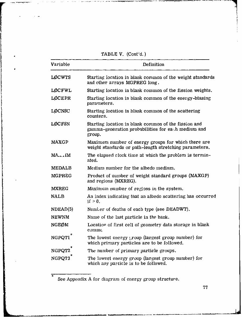
TABLE V. (Cont'd.)
Variable Definition
L0CWTS Starting location in blank common of the weight standardsand other arrays MGPREG long.
L0CFWL Starting location in blank common of the fission weights.
L0CEPR Starting location in blank common of the energy-biasingparameters.
L0CNSC Starting location in blank common of the scatteringcounters.
LOCFSN Starting location in blank common of the fission andgamma-generation probabilities for ea,.h medium andgroup.
MA.XGP Maximum number of energy groups for which there areweight standards or path-length stretching parameters.
MA.,,IM The elapsed clock time at which the problem is termin-ated.
MEDALB Medium number for the albedo medium.
MGPREG Product of number of weight standard groups (MAXGP)and regions (MXREG).
MXREG Maximum number of regions in the system.
NALB An index indicating that an albedo scattering has occurredif > 0.
NDEAD(5) NumLer of deaths of each type (see DEADWT).
NEWNM Name of the last particle in the bank.
NGEOM Location of first cell of geometry data storage in blankconimic
NGPQT1 The lowest -nergy f,roup (largest group number) forwhich primary particles are to be followed.
NGPQT2 The number of primary particle groups.
NGPQT3 The lowest energy group (largest group number) forwhich any particle is to be followed.
See Appendix A for diagram of energy group structure.
77
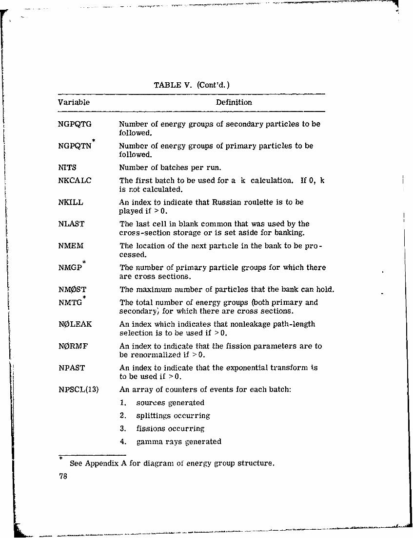
TABLE V. (Cont'd.)
Variable Definition
NGPQTG Number of energy groups of secondary particles to befollowed.
NGPQTN Number of energy groups of primary particles to befollowed.
NITS Number of batches per run.
NKCALC The first batch to be used for a k calculation. If 0, kis not calculated.
NKILL An index to indicate that Russian roulette is to beplayed if > 0.
NLAST The last cell in blank common that was used by thecross-section storage or is set aside for banking.
NMEM The location of the next particle in the bank to be pro -cessed.
NMGP The number of primary particle groups for which thereare cross sections.
NM0ST The maximum number of particles that the bank can hold.
NMTG The total number of energy groups (both primary andsecondary'/ for which there are cross sections.
NOLEAK An index which indicates that nonleakage path-lengthselection is to be used if > 0.
NORMF An index to indicate that the fission parameters are tobe renormalized if > 0.
NPAST An index to indicate that the exponential transform isto be used if > 0.
NPSCL(13) An array of counters of events for each batch:
1. sources generated
2. splittings occurring
3. fissions occurring
4. gamma rays generated
See Appendix A for diagram of energy group structure.
78
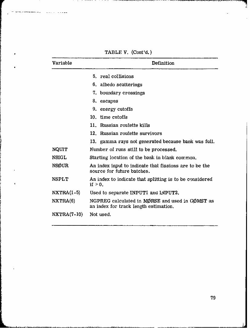
TABLE V. (Cont'd.)
Variable Definition
5. real collisions
6. albedo scatterings
7. boundary crossings8. escapes
9. energy cutoffs
10. time cutoffs
11. Russian roulette kills12. Russian roulette survivors
13. gamma rays not generated because bank was full.
NQUIT Number of runs still to be processed.
NSIGL Starting location of the bank in blank common.
NS0UR An index input to indicate that fissions are to be thesource for future batches.
NSPLT An index to indicate that splitting is to be consideredif >0.
NXTRA(1-5) Used to separate INPUT1 ana INPUT2.
NXTRA(6) NGPREG calculated in MORSE and used in G0MST asan index for track length estimation.
NXTRA(7-10) Not used.
79
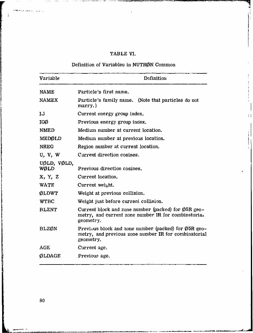
TABLE VI.
Definition of Variables in NUTR0N Common
Variable Definition
NAME Particle's first name.
NAMEX Particle's family name. (Note that particles do notmarry.)
IJ Current energy group index.
IGO Previous energy group index.
NMED Medium number at current location.
MED0LD Medium number at previous location.
NREG Region number at current location.
U, V, W Carrent direction cosines.
U0LD, VOLD,WOLD Previous direction cosines.
X, Y, Z Current location.
WATE Current weiiht.
0LDWT Weight at previous collision.
WTBC Weight just before current collision.
BLZNT Current block and zone number (packed) for 05R geo-metry, and current zone number IR for combinatoria±geometry.
BLZ0N Previuus block and zone number (packed) for 05R geo-metry, and previous zone number IR for combinatorialgeometry.
AGE Current age.
0LDAGE Previous age.
80

TABLE VII.
Definitions jf Variables in USER Common
Variable Definition
AGSTRT Initial chronological age to be assigned to sourceparticles.
WTSTRT Initial weight to be assigned to source particles.
XSTRT Initial x position to be assigned to source particles.
YSTRT Initial y position to be assigned to source particles.
ZSTRT Initial z position to be assigned to source particles.
DFF Normalization for adioint problems.
EBOTN Lower energy boundary (eV) of last neutron group(group NMGP).
EBOTG Lower energy boundary (eV) of last gamma-ray group(group NMTG).
TCUT Chronological age limit.I0 Logical unit for output.
I1 Logical unit for input.
IADJM Adjoint switch (> 0 for adjoint problem).
NGPQT1NGPQT1 Problem -dependent energy group limits (see AppendixNGPQT3 A).
NGPQTG Group number of lowest energy gamma-ray group to b,3treated.
NGPQTN Group number of lowest energy neutron group to betreated.
NITS Number of batches to be run.
NLAST Last cell in blank common used by random walk package.
NLEFT Number of cells in blank common available to user.
NMGP Number of primary particle energy groups.
NMTG Total number of energy groups.
NSTRT Number of source particles for each batch.81
{a

TABLE VIII.
Definitions of Variables in Common G0ML0C
Variable Definition
KMA Starting location for the array MA containing integerdata for each code zone,
KFPD Starting location for the array FPD containing real datafor each code zone.
KLCR Starting location for the array L0CREG(I) which containsthe starting location in the MA array for the Ith codezone data.
KNBD Starting location for the array NUMB0D(I) which con-tains the number of bodies for the Ith code zone.
KI0R Starting location for the array IR0R(I) which containsthe index of the corresponding input zone for the Ithcode zone.
KRIZ Starting location for the array MIRZ(I) which containsthe index of the MORSE region corresponding to the ]th
geometry input zone.
KRCZ Starting location for the array MRCZ(I) which containsthe index of the MORSE region corresponding to the Ithgeometry code zone.
KMIZ Starting location for the array MMIZ(I) which containsthe index of the MORSE media corresponding to the Ithgeometry input zone.
KMCZ Starting location for the array MMCZ(I) which containsthe index of the M0RSE media corresponding to the Ithcode zone.
KKR1 Starting loca~'ion for the array KRI(L) contains the firstcode zone which was made from the Lth input zone.
KKR2 Starting location for the array KR2(L) contains the lastcode zone which was made from the Lth input zone.
KNSR Starting location for array NS0R which contains the codezones in which source particles have been found.
82
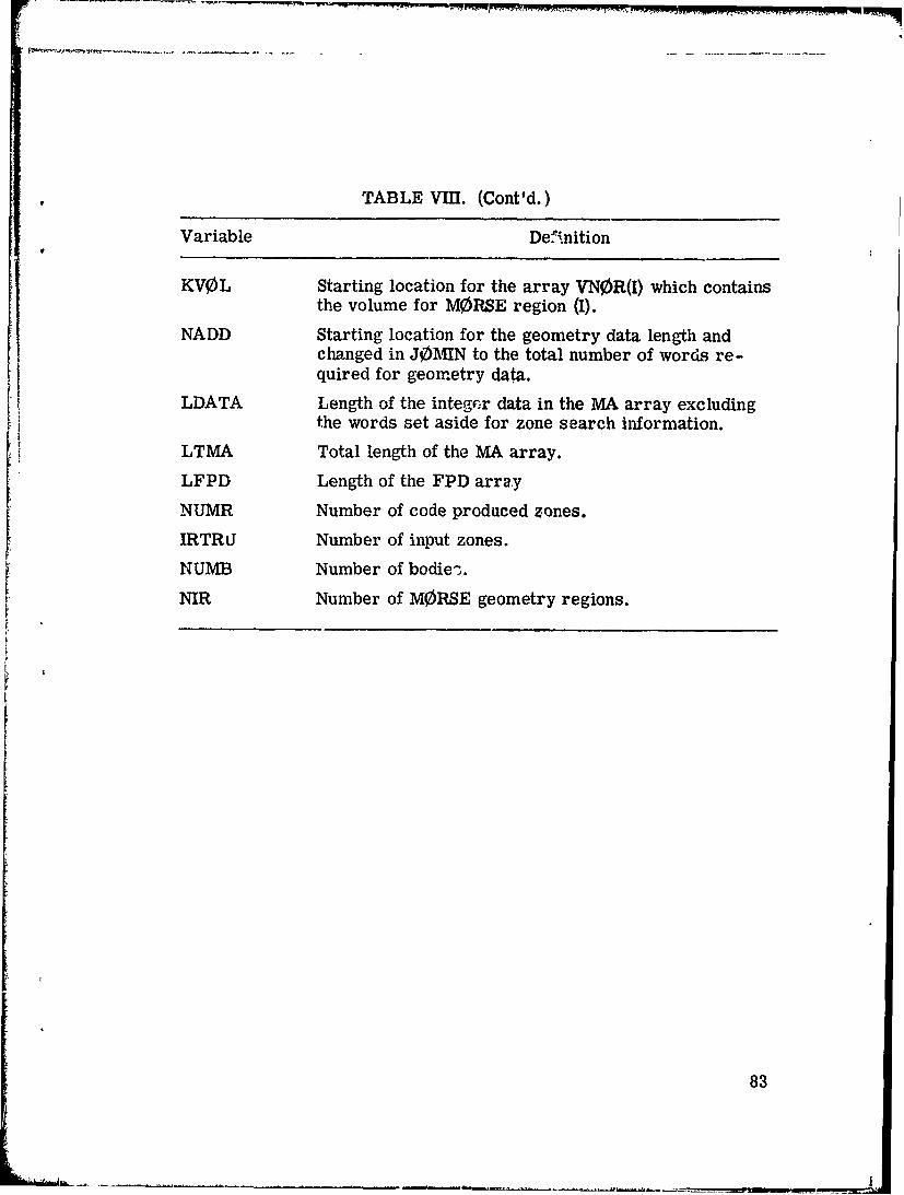
TABLE V-II. (Cont'd.)
Variable Definition
KVOL Starting location for the array VNOR(I) which containsthe volume for MORSE region (I).
NADD Starting location for the geometry data length andchanged in JOMIN to the total number of words re-quired for geometry data.
LDATA Length of the intege;r data in the MA array excludingthe words set aside for zone search information.
LTMA Total length of the MA array.
LFPD Length of the FPD array
NUMR Number of code produced zones.
IRTRiJ Number of input zones.
NUMB Number of bodies.
NIR Number of MORSE geometry regions.
83

TABLE IX.
Definitions of Variables in Common L0CSIG
Variable Definition
ISTART Starting location for the total cross-section vector forthe first medium.
ISCC0G Starting location i,. the scattering cross-section veecorfor the first medium.
INABOG Starting location for the non-absorption vector for thefirst medium.
IGAB0G Starting location for the gamma-ray production vectorfor the first medium.
IFP0RG Starting location for v Zf , the fission neutron productionvector for the first medium.
IFNGP Starting location for the primary-secondary transferprobability matrix.
IFSP0G Starting location of the primary downscatter probabilitymatrix.
IDSGOG Starting location of the secondary downscatter prob-ability matrix.
IPRBNG Starting location of the primary scattering angle prob-ability matrix.
IPRBGG Starting location of the secondary scattering angle prob-ability matrix.
ISCANG Starting location of the primary scattering angle matrix.
ISCAGG Starting location of the secondary scattering anglematrix.
ISP0RG Size of storage needed for each medium, not includingLegendre coefficients.
84
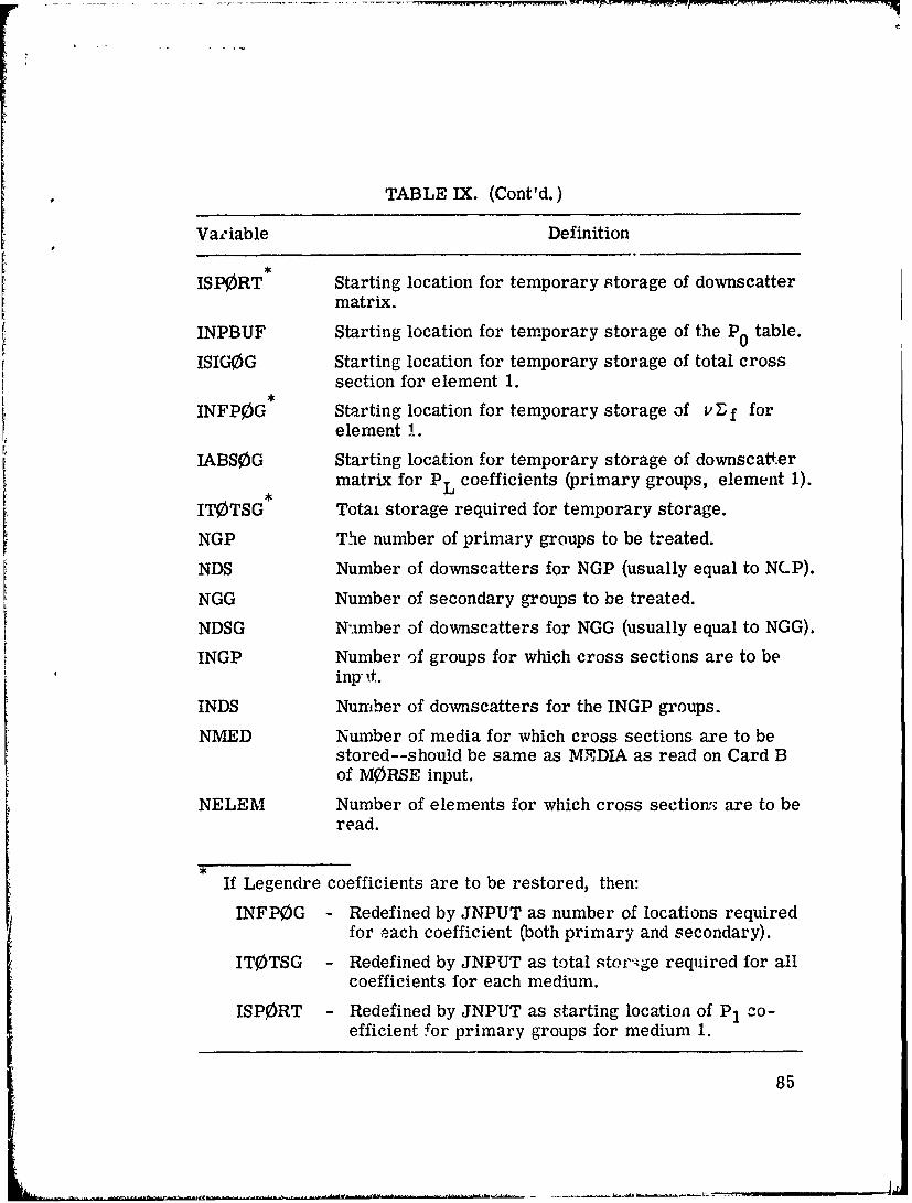
TABLE IX. (Cont'd.)
Variable Definition
ISPORT Starting location for temporary storage of downscattermatrix.
INPBUF Starting location for temporary storage of the P0 table.
ISIG0G Starting location for temporary storage of total crosssection for element 1.
,
INFP0G Starting location for temporary storage of v f forelement 1.
IABS0G Starting location for temporary storage of downscatfermatrix for PL coefficients (primary groups, element 1).
IT0TSG Totai storage required for temporary storage.
NGP The number of primary groups to be treated.
NDS Number of downscatters for NGP (usually equal to NCP).
NGG Number of secondary groups to be treated.
NDSG Number of downscatters for NGG (usually equal to NGG).
INGP Number of groups for which cross sections are to beinp-it.
INDS Number of downscatters for the INGP groups.
NMED Number of media for which cross sections are to bestored--should be same as MEDIA as read on Card Bof MORSE input.
NELEM Number of elements for which cross section;' are to beread.
If Legendre coefficients are to be restored, then:
INFP0G - Redefined by JNPUT as number of locations requiredfor each coefficient (both primary and secondary).
IT0TSG - Redefined by JNPUT as total stor'.ge required for allcoefficients for each medium.
ISP0RT - Redefined by JNPUT as starting location of P1 co-efficient !or primary groups for medium 1.
85
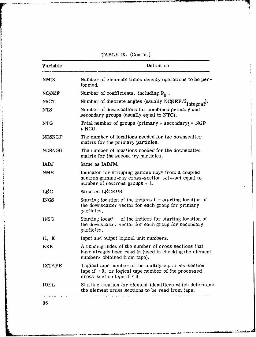
TABLE IX, (Cont'd.)
Variable Definition
NMIX Number of elements times density operations to be per-
formed.
NC0EF Number of coefficients, including P 0
NSCT Number of discrete angles (usually NC0EF/2 integral)
NTS Number of downscatters for combined primary andsecondary groups (usually equal to NTG).
NTG Total number of groups (primary + secondary) = NGP4 NGG.
NDSNGP The number of locations needed for tie downscattermatrix for the primary particles.
NDSNGG The namber of locotions needed for the downscattermatrix for the seconc ,ry particles.
IADJ Same as IADJM.
NME Indicator for stripping gamma rays from a coupledneutron gamnma-ray cross-sectior set--set equal tonumber of neutrons groups + 1.
LOC Same as LOCEPR.
INGS Starting location of the indices fi -- starting location ofthe downscatter vector for each group for primaryparticles.
INSG Starting locat;* of the indices for starting location oftne downscattLt. vector for each group for secondaryparticies.
II, 10 Input and output logical unit numbers.
KKK A running index of the number of cross sections thathave already been read in (used in checking the elementnumbers obtained from tape).
IXTAPE Logical tape number of the multigroup cross-sectiontape if > 0, or logical tape number of the processedcross-section tape if < 0.
IDEL Starting location for element identifiers which determinethe element cross sections to be read from tape.
86

TABLE IX. (Cont'd.)
Variable Definition
ITEML Amount of storage for primary and secondary groupdownscatters per element.
ITEMG Starting location for temporary storage of downscattermatrix for PL coefficients (secondary groups) forelement 1.
IRSG Statting location of the mixing parameters.IRDSG Switch to print the cross sections and to test the card
sequence as they are read if > 0 (test card sequenceonly if = 0, and does neither if < 0).
ISTR Switch to print cross sections as they are stored if>0.
IPRIN Switch to print angles and probabilities if > 0.
IFMU Switch to print intermediate results of A Is calculationif >0.
IM0M Switch to print moments of angular distribution if > 0.
IDTF Switch to signal that input format is DTF-IV format if> 0; otherwise, ANISN format is assumed.
ISTAT Flag to restore Legendre coefficients for next-flightestimates if > 0.
IPUN Switch to print results of bad Legendre coefficients if>0.
NUS Number of groups of upscatter.
NGN Not use - presently.
IHT Location of T, T in the cross-section table, currentlyset to 3 in XSEC.
INUS Starting location for the upscattering vector for thefirst medium.
INUSN Number of impossible first moments found in the crosssections.
INGN Starting location for the photoneutron production vectorfor the first medium (not used at present--same asINUS).
87

TABLE IX. (Cont'd.)
Variable Defiaxtion
INGNP Starting location for the secondary-primary transferprobability matrix (not used at present--same as INUS).
INNN Starting location for the array of the number of down-scatter groups for each primary group.
IGGG Starting location for the array of the number of down-scatter groups for each secondary group.
88
~88

TABLE X.
Definitions of Variables in Common GTSC1
Variable Definition
NPT(16) Number of points per supergroup for each medium.(Only 16 media are allowed.) Redefined at end of
GTSCT as the total storage required for each crosssection for each medium.
NXSECT(17) Starting location of point cross sections for each
medium.
NDSGP Total storage required per supergroup for all media.
I1, 10 Input and output logical unit numbers.
I06RT Logical tape number of 06R point cross-section tape.
IGQPT Last MORSE multigroup for which point cross sectionswill be used (< NMGF'.
NEGPS Number of supergroup boundaries.
ESPD(100) Energy boundaries (in eV) of the supergroups (only 100supergroups are allowed).
NNIC Starting location of the point cross sections.
NXPM Number of cross sections per medium
= 1 if total only= 2 if total + scattering= 3 if total, scattering, and v *fission.
NINC Index for locating point cross sections. Used as flag inFISGEN to determine if transport process has begun.
89
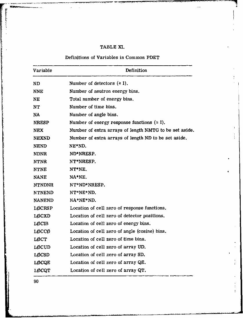
TABLE XM.
Definitions of Variables in Common PDET
Variable Definition
ND Number of detectors (2 1).
NNE Number of neutron energy bins.
NE Total number of energy bins.
NT Number of time bins.
NA Number of angle bins.
NRESP Number of energy response functions (z 1).
NEX Number of extra arrays of length NMTG to be set aside.
NEXND Number of extra arrays of length ND to be set aside.
NEND NE*ND.
NDNR ND*NRESP.
NTNR NT*NRESP.
NTNE NT*NE.
NANE NA*NE.
NTNDNR NT*ND*NRESP.
NTNEND NT*NE*ND.
NANEND NA*NE*ND.
LOCRSP Location of cell zero of response functions.
LOCXD Location of cell zero of detector positions.
LOCIB Location of cell zero of energy bins.
LOCC0 Location of cell zero of angle (cosine) bins.
L0CT Location of cell zero of time bins.
LOCUD Location of cell zero of array UD.
L0CSD Location of cell zero of array SD.
LOCQE Location of cell zero of array QE.
LOCQT Location of cell zero of array QT.
90
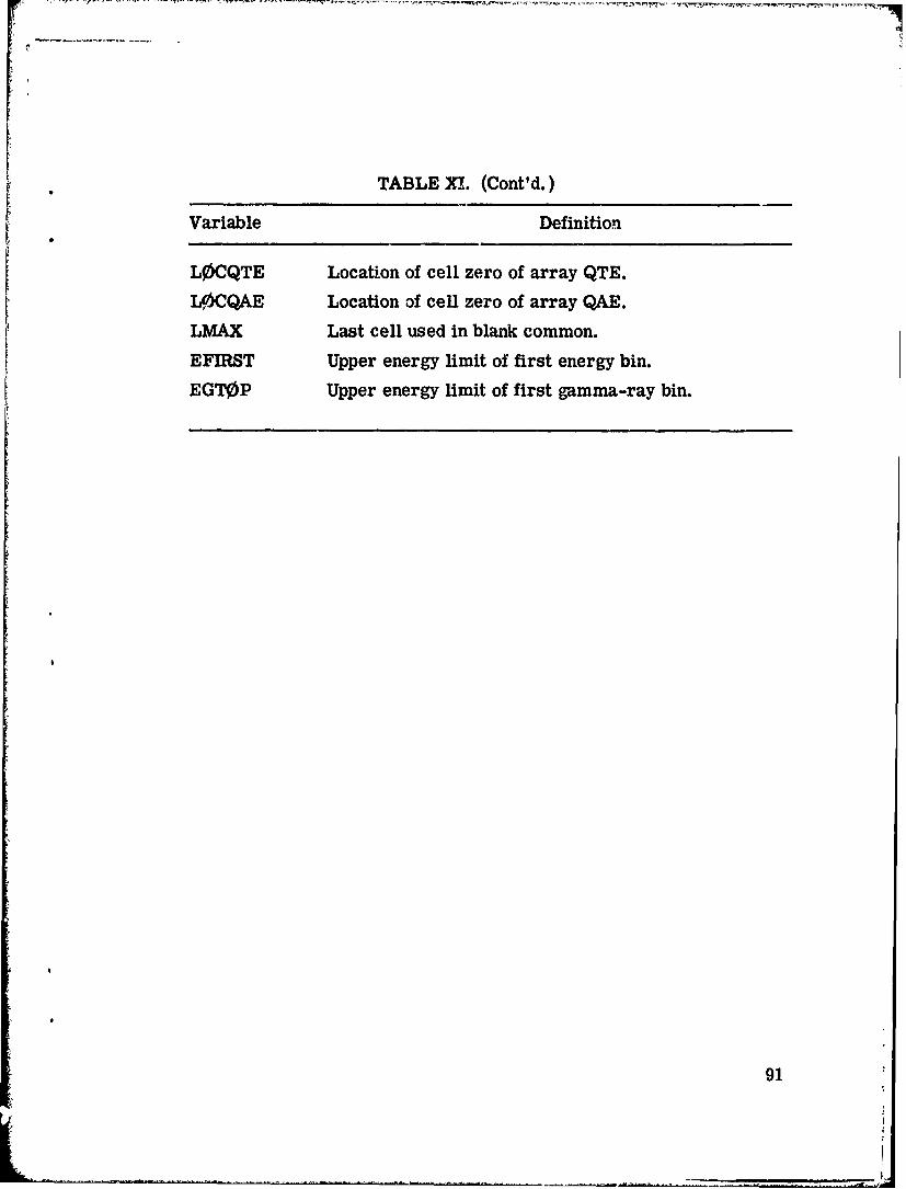
TABLE XI. (Cont'd.)
Variable Definition
L0CQTE Location of cell zero of array QTE.
LOCQAE Location of cell zero of array QAE.
LMAX Last cell used in blank common.
EFIRST Upper energy limit of first energy bin.
EGT0P Upper energy limit of first gamma-ray bin.
91

TABLE XII.
Definitions of Variables in Common FISBNK
Variable Definition
MFISTP Index to indicate that fissions are to be treated if > 0.
NFISBM Location in blank common of cell zero of the fissionbank.
NFISH Number of fissions produced in the previous batch(generation).
FTOTL Total fission weight from all collisions in this batch(generation).
FWATE Total weight of fission neutrons stored in bank in thisbatch (generation).
WATEF Weight of fission neutron stored in bank.
92

TABLE XIII.
-pItinitions of Variables in Common GEOMCas found in 05R Geometry
Variable Definition
X2, Y2, Z2 Coordinates at tentative end-of-flight or if the trajectoryis in an internal void; X2, Y2, Z2 are the directioncosines of the trajectory.
XI, Y1, Zi Starting coordinates for the particle.
ETA Number of mean free paths to be traversed if flight goesto X2, Y2, Z2.
ETAUSD Number of mean free paths actually traversed after thecall to GEOM.
IBLZ An index to the medium number for the special geometrypackages. For GENERAL GE0M, IBLZ is a packedwork giving the block and zone of the end of flight.
IBZN A dummy variable.
MARK A flag set by GEOM indicating the results of the trajec-tory calculation
= 1 for completed flight= 0 for boundary crossing- -1 for escape= -2 for entering an internal void.
NMED Medium number at end of flight or of medium about tobe entered at a boandary crossing.
NREG Region number at end of flight; not set at boundarycrossings.
93

TABLE XIV.
Definitions of Variables in Common PAREMas found in Combinatorial Geometry
Variable Definition
XB(3) Coordinates of the starting point of the present path.
WB(3) Direction cosines of particle trajectory. Equal to U,V, and W.
IR Combinatorial zone of present particle position.
WP(3) Temporary storage of WB(3).
XP(3) Temporary storage of XB(3).IDBG Set non-zero to initialize a debug printout.IRPRIM Next region to be entered after a call of G1.
NASC Body number of last calculated intersection. Set negativeto indicate source or collision point not on a body sur-face.
LSURF Surface of body NASC where intersection occurred.Positive if particle is entering the body and negativewhen exiting.
NB0 Body number and a sign used to define zones. Input inzone description as positive when zone is cor'ained inbody and as negative if zone is outside body.
LRI Entry surface calculated in GG.
LR0 Exit surface calculated in GG.
RIN Distance to entry calculated in GG.
ROUT Distance to exit calculated in GG.
KL00P Trajectory index of present path incremented in G1.
LOOP Index of last trajectory calculated for body NB0. IfL00P is equal to KL00P, GG returns immediately with3ld values of RIN, ROUT, LRI, and LR,.
ITYPE Body type of body NB0 (indicates BOX, SPH, etc.).
94

Im... .ma , IM MI O-f, W 9 O . I R M •-• •.. -, .-..
TABLE XIV. (Cont'd.)
Variable Definition
PINF Machine infinity.
N0A Not used.
DIS'' Distance from XB(3) to present point.
19
95

TABLE XV.
Definitions of Variables in Common 0RGI*
Variable Definition
INV- ASet 1 in GI if trajectory end point is reached before
next intersection. Otherwise set to 0.
DISTO Distance from point XB(3) to next scattering point.Used in GI to avoid calculating the next zone if ascattering event occurs before the intersection.
NMEDG Zone number IR from a LO0KZ call. Stored in BLZNTby MSOUR.
Note: Variab] names are not the same in all routines.
96
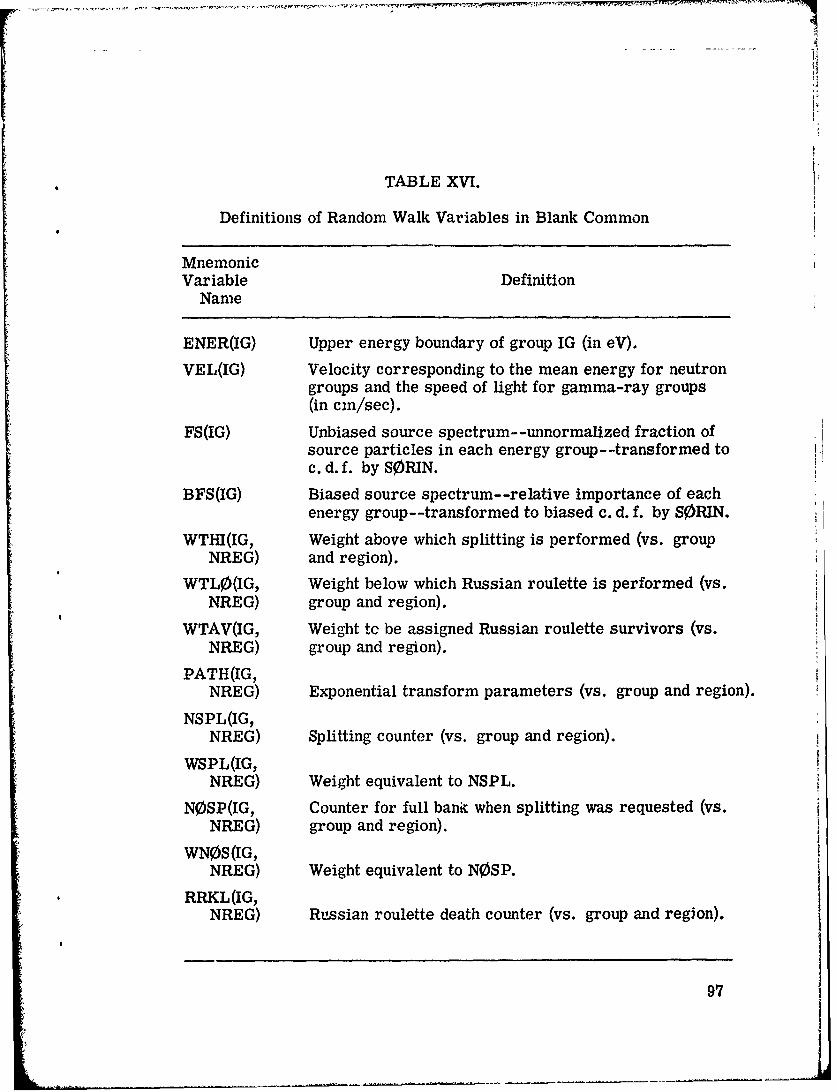
TABLE XVI.
Definitions of Random Walk Variables in Blank Common
MnemonicVariable Definition
Name
ENER(IG) Upper energy boundary of group IG (in eV).
VEL(IG) Velocity corresponding to the mean energy for neutrongroups and the speed of light for gamma-ray groups(in cm/sec).
FS(IG) Unbiased source spectrum- -unnormalized fraction ofsource particles in each energy group--transformed toc. d. f. by SORIN.
BFS(IG) Biased source spectrum- -relative importance of eachenergy group--transformed to biased c. d. f. by SORIN.
WTHI(IG, Weight above which splitting is performed (vs. groupNREG) and region).
WTL0(IG, Weight below which Russian roulette is performed (vs.NREG) group and region).
WTAV(IG, Weight tc be assigned Russian roulette survivors (vs.NREG) group and region).
PATH(IG,NREG) Exponential transform parameters (vs. group and region).
NSPL(IG,NREG) Splitting counter (vs. group and region).
WSPL(IG,NREG) Weight equivalent to NSPL.
NOSP(IG, Counter for full bank when splitting was requested (vs.NREG) group and region).
WN0S(IG,NREG) Weight equivalent to N0SP.
RRKL(IG,NREG) Russian roulette death counter (vs. group and region).
97
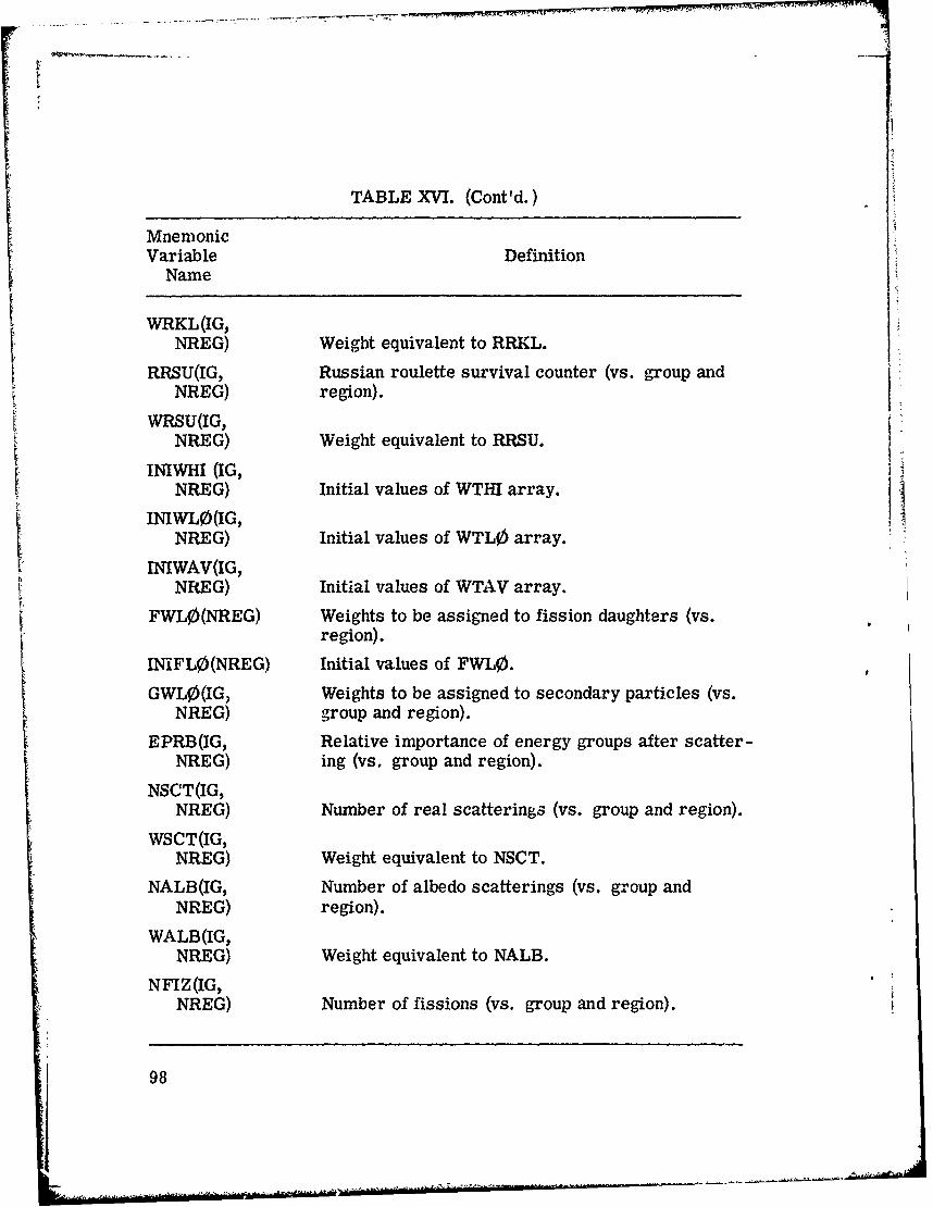
t
TABLE XVI. (Cont'd.)
MnemonicVariable Definition
Name
WRKL(IG,NREG) Weight equivalent to RRKL.
RRSU(IG, Russian roulette survival counter (vs. group andNREG) region).
WRSU(IG,NREG) Weight equivalent to RRSU.
iiINIWHI (IG,
NREG) Initial values of WTHI array.
INIWL0(IG,NREG) Initial values of WTL0 array.
INIWAV(IG,NREG) Initial values of WTAV array.
FWLO(NREG) Weights to be assigned to fission daughters (vs.region).
INIFL0(NREG) Initial values of FWLO.
GWL0(IG, Weights to be assigned to secondary particles (vs.NREG) group and region).
EPRB(IG, Relative importance of energy groups after scatter-NREG) ing (vs. group and region).
NSCT(IG,NREG) Number of real scatterings (vs. group and region).
WSCT(IG,NREG) Weight equivalent to NSCT.
NALB(IG, Number of albedo scatterings (vs. group andNREG) region).
WALB(IG,NREG) Weight equivalent to NALB.
NFIZ(IG,NREG) Number of fissions (vs. group and region).
98
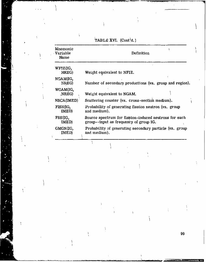
TABLE XVI. (Cont d.)
Mnemonic• 'i *Variable Definition
Name
WFIZ(IG,NREG) Weight ejuivalent to NFIZ.
NGAM(IG,NREG) Number of secondarsy productions (vs. group and region).
WGAM(IG,,NREG) Weight equivalent to NGAM.
NSCA(IMED) Scattering counter (vs. cross-sectioh6 medium).
FISH(IG, Probability of generating fission neutron (vs. groupIMED) and medium).
FSE(IG, Source spectrum for fission-induced neutrons for eachIMtD) group--input as frequency of group IG.
GMGN(IG, Probability of generating secondary particle (vs. groupIMED) and medium).
99

IV. THE PICTURE PROGRAM
This program is used to obtain printer plots of twro-dimension".l
slices through the three-dimensional geometry described by the combi-
natorial geometry (Cd) package. The 05R geometry version10 has
been modified for use with CG and some minor changes to the program
have been made. It is now possible to obtain a picture the full width of
a computer page and the logic for determining the medium and/or region
number has been changed so that a test of the geometry ray tracing cap-
ability is also made. That is, instead of just testing the routine L00KZ,
this modification forces the geometry package to execute the routines
and logic used during the random walk process. 'This program has been
very useful in debugging geometry input. It is suggested tiat any com-
plex geometry be tried in this program before using it in the MORSE
code. A sample problem is provided. Besides the geometry package,
a main program, PICTURE, and two routines, MESH and PRINT, are re-
quired. A discussion of these routines is included and a definition of
the variables in common, PICT, is given in Table XVII.
Preceding page blank
101
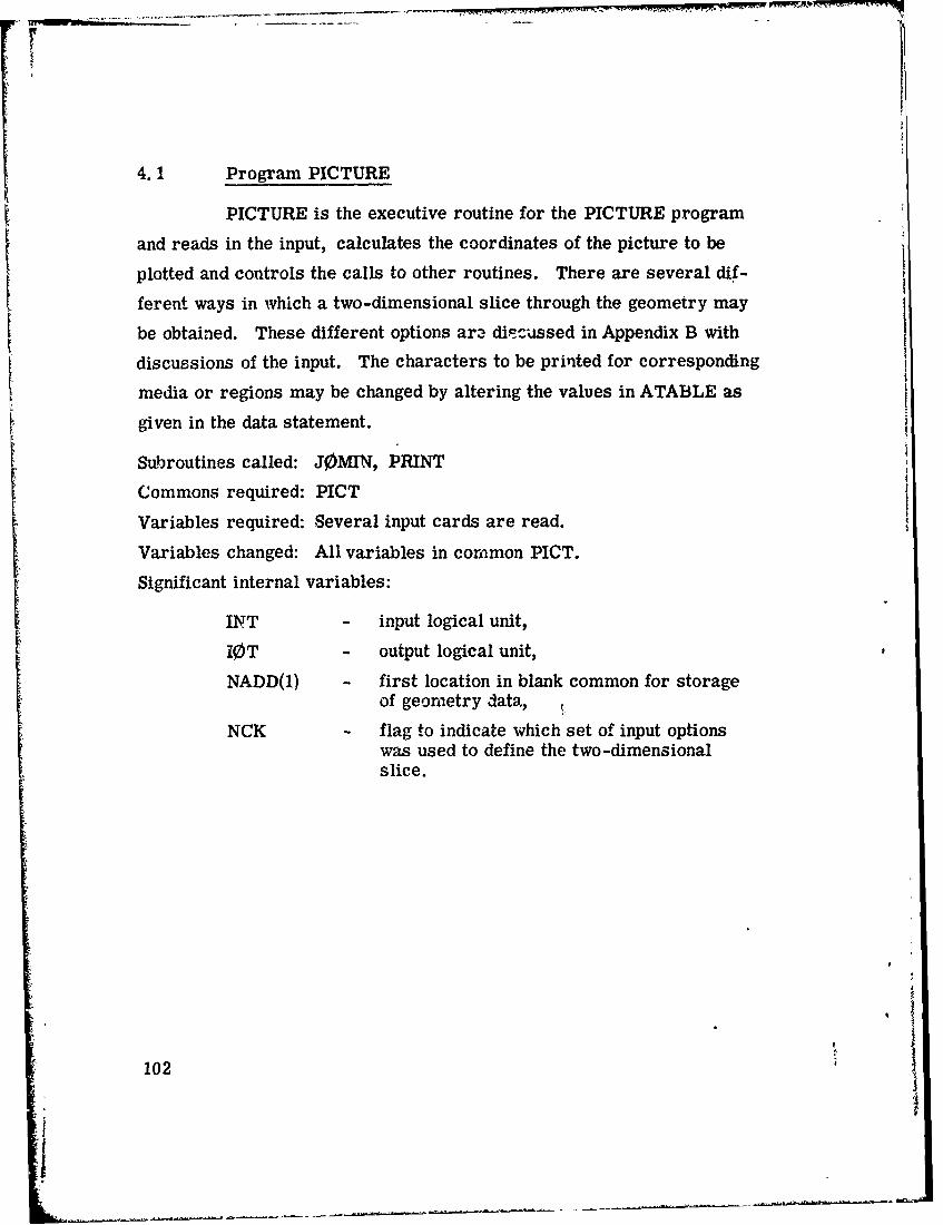
4.1 Program PICTURE
PICTURE is the executive routine for the PICTURE program
and reads in the input, calculates the coordinates of the picture to be
plotted and controls the calls to other routines. There are several dif-
ferent ways in which a two-dimensional slice through the geometry may
be obtained. These different options ar2 diPcussed in Appendix B with
discussions of the input. The characters to be printed for corresponding
media or regions may be changed by altering the values in ATABLE as
given in the data statement.
Subroutines called: JOMIN, PRINT
Commons required: PICT
Variables required: Several input cards are read.
Variables changed: All variables in common PICT.
Significant internal variables:
INT - input logical unit,
i0T - output logical unit,
NADD(1) - first location in blank common for storageof geometry data, !
NCK - flag to indicate which set of input optionswas used to define the two-dimensionalslice.
102
J.

* Program PICTURE
START
SLeF inpu1t/output dev~ices -to -51and -6.
[!ZýO Symlbol op~tionl.
Cal 1J0MIIN to input gcoinctry data.
F1/0: Opinnmber of pictures for thisg-eometry, m-?dia or region title.
1 : Picture coordinates upper left an -dlower ri ht corner.
11/: drecionnumbers for Uand V axes.
11/0: interval nunmler and size.j
=Were both upper left and lower'ye Clcatright coordinates gi7-en? . Calculaiven
No NU cr NV!;CK~lgiven DELU
repe(at ffor V)Use inpu( PEIO'EV values Ind -U, NV.
C. 'I PRINT
103
4.2 Subroutine PRINT (KXX, KYY, ATAB"JE)
This routine controls the printing of the picture. First it is
determined if the picture is to be more than one "page" (130 columns)
wide and then for each iine of the picture on the first page the infor-
mation to be printed is determined by calling MESH and printed with a
130A1 format. The next lines are then calculated and printed until that"O page" is finished. Note that a page refers to width not length. Thus,
as much detail may be obtained as necessary in both directions by piec-
ing together the output.
Called from: PICTURE
Subroutine called: MESH
Commons required: PICT
Variables required:
KXX - number of intervals in the U direction(direction of paper movement throughthe printer),
KYY - number of intervals in the V direction(line),
ATABLE - table of characters to be printed.
Significant interval variable:
NPAGES - number of subpictures required to coverthe width of the total picture,
IOT - output logical unit,
NV - number of characters per line (characters/page width).
104

Subroutine PRINT
TART
Initialize interval parameters.TISet output device to 6.1
ICalculate number of pages.
ISet coordinates for one line.
Call MESH to store media or region numberin NS'IR for one line.0T
I hange media or region numbersto output symbol.
jOutput one line of picture.]I
MMKX YeU{ s there a~nother line ?)
MM<KXX INo
SYes Is there another page?7)N<NPAGES N
S~105

4.3 Subroutine MESH (XS, YS, ZS, NV)
Subroutine MESH is used by the PICTURE package to set up
one line of print in the array NSTOR. Both for efficiency and to debug
the combinatorial geometry package, this version has been modified to
work exactly like particle tracking. L00KZ is first called to deter-
mine the zone of the first grid point. A trajectory to the last grid point
is then initialized, and successive calls to GI "track" a particle to the
last point, setting the region of each grid point in NST0R. By setting
IRG negative, *.ro, or positive, either NREG, IR, or NMED will be
stored in the print array NST0R.
Called from: PRINT
Subroutines called: L00KZ, GI
Commons required: PICT, G0MLOC, PAREM, 0RGI, blank.
Variables required:
XS, YS, ZS - coordinates of first grid point,
NV - number of grid points,
DELV - distance between grid points,
IRG - flag to print NREG, IR, or NMED if IRGis negative, zero, or positive.
Variables changed: NST0R - print array.
Significant internal variables:
J - grid point index,
IST0R - value to be stored in NSTOR betweensuccessive boundary crossings.
106
I

Subroutine MESH
PSTART
l .LýZ to determine IR of firstrion.
[Store NRE, or NMED in NSTOR (1) dependin on rG.
Initialize combinatorial geometry trajectory fromthe first to the last grid point.
I e etgrid point t .
SSet ISTOR to NREG, IR or NMED depending on TRG.I
From DIST, determine last grid point beforeboundary crossing or trajectory completion.
Yes -• last grid point less than the next grid point?(Distance is less than grid resolution. ) ]
No
Loop from next to last grid points.
I StoResrr in NST'R array.
[Set next point to last point +1.
WRi --IPRIMIZLFIs trajectory complete - No
Yes
R E TU R
107

TABLE XVH.
Definition of Variables in Common PICT
Variable Definition
DELU The increment in geometry units between lines in thepicture in the U direction.
DELV The increment in geometry units between lines in thepicture in the V direction.
XO, YO, ZO The coordinates in goometry units defining the firstpoint (upper left hand corner) of the picture.
XU, YU, ZU The length (in direction U) of the picture in geometryunits.
XV, YV, ZV The width (in direction V) of the picture in geometryunits.
NSTOR(130) An array used to store the medium, region, or zonenumber for one line of the picture.
IRG A flag indicating that region, zone, or medium geo-metry parameter should be printed if ERG is negative,zero, or positive, respectively.
Used in the PICTURE program.
108
V. MORSE SAMPLE PROBLEMS
5. 1 Sample Problem Number 1
This sample problem is similar to that used previously(7)
which calculates neutrons and secondary gamma rays in infinite homo-
geneous air. The source is a 12. 2- to 15-MeV neutron source. Two
types of estimators are used in the analysis of the particle histories.
First, a boundary-crossing estimator is used for five spherical shells.
(This part of the problem is similar to the MORSE sample problem.)
Second, a collision density estimator is used in RELCOL for nine de-
tector regions (detectors 6-14). By choosing the spherical shells as
the midpoints of the regions, an internal check is provided. Also, by
choosing the geometry regions to correspond to the collision density
detectors, the results from SAMB0 can be compared with results from
ENDRUN. With the inclusion of the combinatorial geometry package,
an additional estimator based on track length/unit volume has been
added with results also output in ENDRUN. Both the collision density
and track length per unit volume estimators are obtained for the geo-
metry regions without s ecific coding.
Since the collision density estimator in RELC0L scores
4R'p there will be some differences between these estimates and
those from the collision .. ensity estimator output in ENDRUN which2
scores 4if (R) (p. (The symbols K ) denote an average over a spatial
region.)
Table XVIII illustrates the comparison for one of several
sets of answers as calculated by the various estimators. Descriptions
of the user routines INSCOR, RELCOL, and BDRYX required for the
sample problem are given.
109
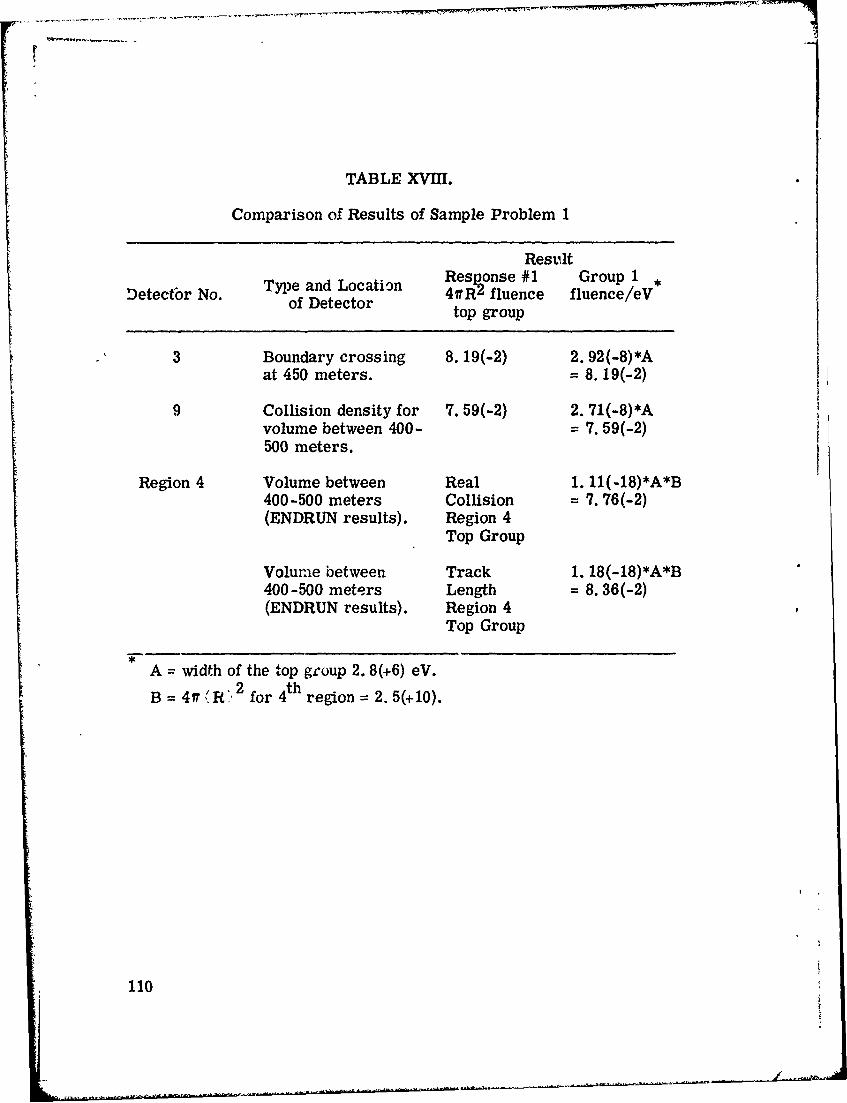
TABLE XVIII.
Comparison of Results of Sample Problem 1
Result
Type and Location e#1 Group 1 IDetector No. of Detector 4fRý, fluence fluence/eV
top group
3 Boundary crossing 8. 19(-2) 2. 92(-B)*Aat 450 meters. = 8.19(-2)
9 Collision density for 7. 59(-2) 2. 71(-8)*Avolume between 400- = 7. 59(-2)500 meters.
Region 4 Volume between Real 1. 11(-18)*A*B400-500 meters Collision = 7. 76(-2)(ENDRUN results). Region 4
Top Group
Volume between Track 1. 18(-18)*A*B400-500 meters Length = 8. 36(-2)(ENDRUN results). Region 4
Top Group
A = width of the top group 2. 8(+6) eV./ 2 th
B = 0•'R', for 4t region = 2. 5(+10).
110

5.1.1 Subroutine INSC0R - Sample Problem Number 1
This user routine is used to calculate the volume of each of
the detector regions (detectors 6-14) in the sample problem. The re-
ciprocal of the volume is stored in the array in blank common set aside
for FACT, a detector -dependent normalization. Because two types of
estimators are used in the problem, normalization values of 1 are
stored for the boundary detectors. The detector number NDC for the
last boundary crossing detector (in this case, 5) must be input.
Called from: SCORIN
Subroutines called: None
Commons required: PDET, USER, DETCUT, blank.
Variables required:
NDC - the number of the last boundary crossingdetector. Detector radii from blankcommon.
Variables changed:
Normalization array in blank common.
111
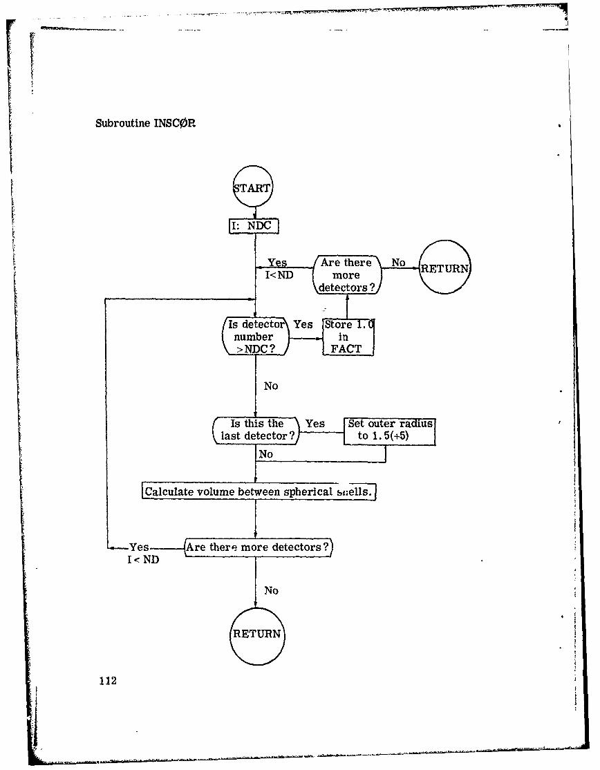
Subroutine INSC0PR
ART
I: NDC
IstYh s thAre there r No u-I< ND |more REUR
adetectors ?
[Is detector• Yes [fr .
C number e ic :\N>NDC?]
No
RETURN
last detector'? to 1. 5(+5)?• to 1.
FC~alculate volume between spherical sfel-7. i]
L--Yes ---- Are there more detectors ?)I<• ND
No
112
' |
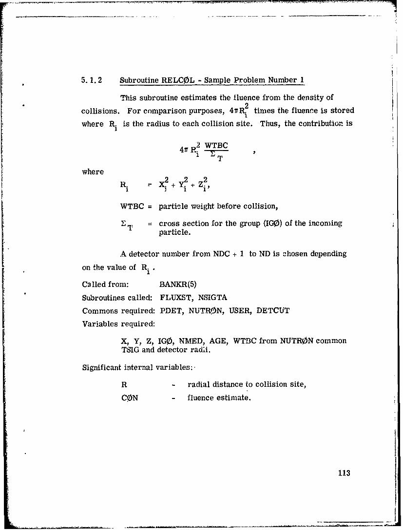
5.1.2 Subroutine RELCOL - Sample Problem Number 1
This subroutine estimates the fluence from the density ofcollisions. For comparison purposes, 4fR.2 times the fluenee is stored
where R. is the radius to each collision site. Thus, the contribution is
4f2 P. WTBCT
where 2 X.+Y2. +Z2,Ri
WTBC = particle weight before collision,
F T = cross section for the group (IGO) of the incomingparticle.
A detector number from NDC + 1 to ND is 3hosen depending
on the value of R.1
Ca led from: BANKR(5)
Subroutines called: FLUXST, NSIGTA
Commons required: PDET, NUTR0N, USER, DETCUT
Variables required:
X, Y, Z, IGO, NMED, AGE, WTBC from NUTRON commonTSIG and detector radii.
Significant internal variables:
R - radial distance to collision site,
CON - fluence estimate.
113
________________________

KI
Subroutine RELCOL
S [Calculate radii of collision site from origin.
Call NSIGTA to find total cross section.
F Calculate contributo.
I Determine detector number.
W~as detector 'e-Rduoutsidle of es - RadMAs
RETURN
No
I[C1all FLUXST to store contribution.
RETURN
114
AJ

5.1.3 Subroutine BDRYX -,Sample Problem Number 1
This subroutine is called whenever the particle in the random
walk encounters a change in geometry media. If the source-to-collision
distance corresponds to a detector position, the reciprocal of the cosine
of the angle from the radius vector is used as a fluence estimate.
Called from: BANKR(7)
Subroutines called: ERROR
Commons required: USER, NUTR0N, DET
Variables required:
X, Y, Z, U, V, W, WATE (from common NUTR0N).
Significant internal variables:
R21 - ýadial distance to boundary crossing,R2 - 99% of R21,
R22 - 101% of R21,
Cos - cosine of angle between' particle directionand radius vector,
ABC0S - absolute value of COS,
CON - fluence estimate,.
115

Subroutine I3DRYX
START
Calculate R21, distance from originto boun~dary crossing.
Does R21 corspn oa ~ I raerequested detector positio? tm ags
detector NoYes (detector indicated Position?
by index 1)Yes
Calculate COS, cosine of Incremientangle between particledirection and surface.
ETURN
ETURN Yes -Is the cosine exactly zero?)
PRINT >1. 00111 What is the range of absolute1 1111!ý <. 01ACSMESSAGE _u fCO?00
.-___Call FLUXST Increment
FC0N WAEACS to store NNcontribution
®EU
116

5.2 Sample Problem Number 2
This sample problem( 1 1 ) is used to illustrate the next event
estimator. The neutron and secondary gamma ray spectra at several
point detectors located 104 cm from a polyethylene slab is calculated.
The source is a beam of neutrons with a fission spectrum energy dis-
tribution. The use of the point detector routines to estimate the energy
dependent fluence is illustrated and in particular, for secondary gamma
rays the contribution of the uncollided or first flight gamma rays are
scored in subroutine SGAM. The estimates from real collisions are
made in subroutine RELC0L. Results are recorded in Table XIX in2
units of particles cm source neutron.
TABLE XIX.
Results of Last Flight EstimatorSample Problem
Neutrons/cm 2 Gammas/cm 2
Detector Per PerSource Neutron Source Neutron
1 6.24(-11) 2.36(-11)
2 6.44(-10) 4.82(-11)
3 1.32(-9) 4.93(-11)
4 1.56(-9) 4.94(-11)
5 6.92(-1) 2.15(-3)
117

x;
5.3 Sample Problem Number 3
This sample problem serves two purposes by (1) demonstrat-
ing the use of the PICTURE code, and (2) verifying the tracking capability
of the combinatorial geometry package in a moderately complex three-
dimensional system. In the PICTURE program, subroutine GI is called
from MESH in the exact manner that it is called from G0MST during a
M0PSE calculation. As such, PICTURE works by tracking rays and
thus can be used to debug a combinatorial geometry input.
The sample problem itself is a picture of a tank. The tank
model itself was constructed purely as an illustration of the combina-
torial geometry and is in no way accurate or detailed. Notice that the
use of both the OR operator and the ARB body is demonstrated.
118

nI i + l , , i i i ,* I !
ilI 14 , t n o a . T a a a
so 1, "' - n00 v, Co I
-J ... o . I: I. a :2 cla°1
.. . i . .. ..... I I wc,1 11% .3 :) 0 Uv *3 2
nu r • * ,~,13. ' , I
00 0 E., c3 17is 0 1)13 1'a'., 11 3 3 '7 3 3.1 . 4 ,)L•J. D 3 . ( .0 ( o
04 .Ni so "'O.. 3VDVI * . .7 Z . 1 3 L .31 2 0 1 .2 : 0
t . 0r• • .+ • vso , 47 LI) , • . . •
so u,. o.. .ii . .. .. .., 4, 1 .. . . a' ':o !*4 j '*. -n * .. l %) IIN 1.... . (>tm. - Is M
01 ,, . ... .. m......... . . .. ...............s,.. ... ......... o+ *) 'I 7, 3 2 3 .3!, . 0 + * O.3 73 !'4.. 3 4 • $7 . ,4 • 7, 3)'• • , .) .7 2 3 7 3 (7
01 I '. . ' I4 0: . , ' cI I,
44...4-.*. So - .3 , 4.7.7 . " . .3 .7 . 7 .o •
.f Jl.317 .' I. *:, 33+ (7 .f l .) V 1 . 1 V 't r,. 3 ., *3r .7 .3 2 17 :, :7NNNI V'J I, 1 0..{ (7. Na+ .)J) q.i , I(•4 flhnl.. .4 3, .1 r) -1 .9 () ( 4 7)SI ........ ).. .... ............. .. .. ..J 4 N N N N
In1 zo a a)) + o -" (' I ) ". 1 -. 3 -. 1 €) •-* 31.I v * &) (3(.4 t/ *1) * 4. (2!.4• 3,. *.. . . . . . .I 31+,
"",Lo3 j isI * *
.. ....... . . , . . . ... ..... .
fl4 i34....33. 3 .3 .7 '7 . 2 '.
, ,',,, ,. ,.. . * , . ,,,. ,.. ....... . .. . .
to
4, .... .. ...... 3'732..... .
v' ' Do.. . . .. . . .( .
01 V V '333 0S1~ 3 @ ( 0 N .
111
314~~~o 137.,.,23 'I
( *e I....s:34 . j.I.( Q..I.t'' u., .~ . v. 1. soII~l )( 3.~,3 4~4~. .7 3 3 s 7t', 4 7 3 3 j *o( 3 0
I V.'t.704( .3.., I'4 .. ~ CI.7ffl 3 7 ( t~ 0 119C

I a
-. :111.11
000
03 * a
t:oo
030 00
00 2
c, e! r
.0 Cf 00 0 I
a j
OA. .... ".. a °,v 'o
,a. , ,°- - ° i tI . a
& 0.
120J ';" JI •
S I -I • I a
'aii!J °i T I. . Iii a-aI . ....I I.'o %
1•.o
I Irt~ I-awnl an..a

Jill
JILL
Lills lI~.fr~~fw
III! I in( 'l('Ptinlfloflltf , (w ooosI Il I lv('flflfrmf( ,)n tIft'Ifli :1inrl~ifllaJILL I I itvinl(fcipunin 1irtoin ioo
I5I11 ITI I IVVVVVVIl"l~lU~t
LilI IIt a I I t~ TrwffltW ''f~
Jill
SIL tltittIrt I vvTT~YT rt-. vvTvvtvTvvv
pi I.11 __ _ - ti lttltiitliT l %jTV TtTV7VV.TTVTVVVVVvVVW~
Jillltitl tT ~t~rrVV~y~~V
111133 tt~~~it II Itiit I I I lVVtVItVV I11~ZM
I t i 111 11 11 1 11tll ltnri)jn;rrtV tV v v vvvvT Iy vTt' tV I
C.) ~j n1j:)LCtflf VVVVVVYVVTVVVVI -
3313~35Jiii~ii.4l~hl lilt It1IUvI li~~VVltvvtvt~~33~~33~~~J)3~~~33T3 TVlt tiI tllIvTvw, i Tn .'t, T .T-v v
3 3 3 3 3 3 1 ' 1111 I? I I II 1t Iirtv I I v vvr vtt1v vtvwnnvY qn V CL
373733)333333111;1 1 TIMaII I, tt tvr vV~vvvv n1 noo
333310713t7013t ll tI l I 1111
1111111 it IiIr!nal jpcpnojqnvV TV % 7VVVTT T VT TV arT
33313*43j'43J l I II II I It1t1itl 1wninweI7V , 7TTV7V TVT~Ty VVVY-
3311173 II! I Illa l , t. IVI I Iy ITV V V
11IV 111i 1 1V1 11 Itf 11110 -
itt111 tillJ~I~l' Vt 1:1t,'n1J~~
If'~0 a t'f'l. I I t t I fIrIlI !
tltittlOlllttiTV-VTVlllfV7TVVVV TVVVI
121

APPENDIX A
ENERGY INDEXING SCHEME
For most problems the user does not need to worry about the
energy-indexing scheme used in the MORSE Monte Carlo code. Energies
corresponding to the group boundaries in the forward group structure
are input and the code takes care of the rest. The analysis package
SAMB0 performs the proper bookkeeping for labeling. A diagram for
the energy group structure is given in Fig. Al. However, some clarifi-
cation of the indexing scheme for several types of problems is advanta-
geous. This clarification can perhaps best be made through the use of
examples. Consider a five-group coupled neutron-gamma-ray problem
with the following group boundaries:
Group Energy (eV) with NMGP = 3, NMTG = 5,
1 15(+6) NGPQTN = 3, NGPQTG= 2
2 5(+6)
3 1(+6)
EB0TN 3(+3)
4 10(+6)
5 2(+6)
EB0TG 4(+5)
There are several options which might be considered; namely,
(1) a forward coupled problem, (2) a forward neutron-only problem, (3)
a forward gamma-ray-only problem, (4) an adjoint coupled problem, (5)
an adjoint neutron-only problem, and (6) an adjoint gamma-ray-only
problem. Table AI gives the energies as they are indexed during a
MORSE run. Table AII gives the values of variables NQT1, NQT2, and
NQT3 as they appear in USER common for the same six problems.
Preceding page blank 123
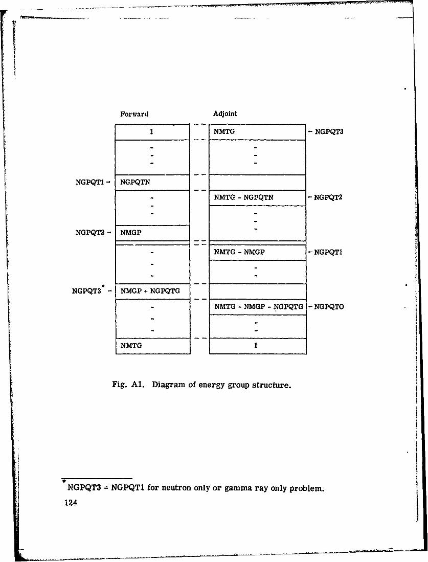
Forward Adjoint
1 NMTG NGPQT3
NGPQT -. NGPQTN
NMTG - NGPQTN -NGPQT2
NGPQT2 - NMGP
NMTG - NMGP -NGPQT1
NGPQT3 -NMGP+NGPQTG
NMTG - NMGP - NGPQTG -NGPQTO
NMTG1
Fig. Al. Diagram of energy group structure.
NGPQT3 =NGPQTl for neutron only or gamma ray only problem.
124

c' ) 0 0
NJ 0
0O CD +' 0
0 0
000
0 4 $4 ý
c~bd
Cd 0 $4_ 4.Q P4 CO tow oq C)
4- 9b-
-.4C 0
sm4 tnLO m- '-l '- '-.
0 GNZ Cd wl c t 44ZoZ -4 V.~
Q) 0I~z~ZZZZ
>2
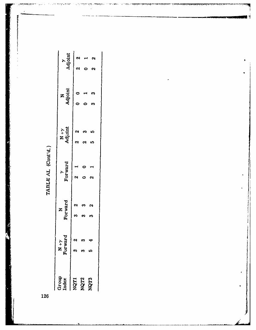
. '- eq
714
*-0 m- c.*
eq m
0 c
C4~ co,
tz, VQ~
126

E-4
PI0
E- E-4 E- E-0 00 H!2 HV H Hz z z z z
a) Z Z 0H H4
E-4 4 p4 z
z 0Z z z Z zz
z*P4 P4 P
z z z z z
p4 a H H- H 0)
z z z Z Z ZCd0
ra
00
a12
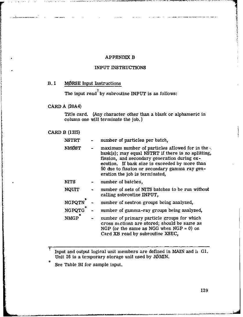
I
APPENDIX B
INPUT INSTRUCTIONS
B. 1 MORSE Input Instructions
The input read' by subroutine INPUT is as follows:
CARD A (20A4)
Title card. (Any character other than a blank or alphameric incolumn one will terminate the job.)
CARD B (1315)
NSTRT - number of particles per batch,
NMOST - maximum number of particles allowed for in the ,,bank(s); may equal NSTRT if there is no splitting,fission, and secondary generation during ex-ecution. If bank size is exceeded by more than50 due to fission or secondary gamma ray gen-eration the job is terminated,
NITS - number of batches,
NQUIT - number of sets of NITS batches to be run withoutcalling subroutine INPUT,
,NGPQTN - number of neutron groups being analyzed,NGPQTG - number of gamma-ray groups being analyzed,
,NMGP - number of primary particle groups for which
cross sections are stored; should be same asNGP (or the same as NGG when NGP = 0) onCard XB read by subroutine XSEC,
Input and output logical unit members are defined in MAIN and ih G1.
Unit 16 is a temporary storage unit used by JOMIN.*
See Table BI for sample input.
129

NMTG - total number of groups for which cross sectionsare stored; should be same as NGP + NGG asread on Card XB read by subroutine XSEC,
NC0LTP 4 set greater than zero if a collision tape is de-sired; the collision tape is written by the userroutine BANKR,
IADJM - set greater than zero for an adjoint problem,
MAX TLM - maximum clock time in minutes allowed for theproblem to be on tlhe computer,
MEDIA - number of cross-section media; should agreeVwh NMED on Card XB read by subroutine XSEC,
MEDALB - albedo scattering medium is absolute value o0MEDALB; it
= 0, no albedo information to be read in,
< 0, albedo only problem--no cross sectionsare to be read,
> 0, coupled albedo and transport problem.
CARD C (415, 5El0. 5)
ISOUR - source energy group if > 0, if ISOUR - 0,S0RIN is called for input of Cards El and E2,
NGPFS - rumber of groups for which the source spectrumis to be defined. If IS0UR 5 0, NGPFS • 2,
ISBIAS no source energy biasing if set equal to zero;otherwise the source energy is to be biased,and Cards E2 are required,
N0TUSD - an unused Variable,
WTSTRT - weight assigned to each source particle,
EB0TN - lower energy limit of lowest neutron group (eV)(group NMGP),
EBOTG - lower energy limit of lowest gamma-ray group(eV) (group NMTG),
,'I
See Table BI for sample input,,
130
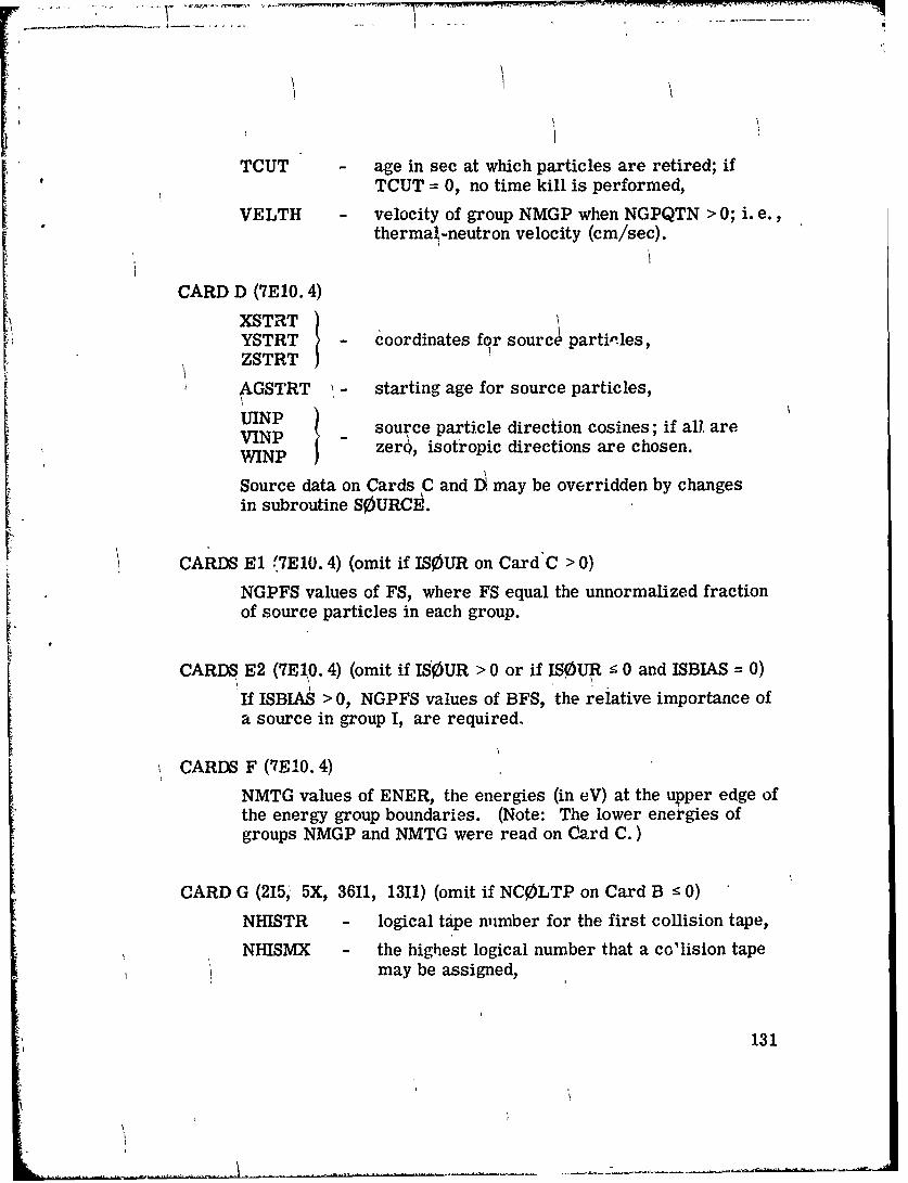
TCUT age in sec at which particles are retired; ifTCUT = 0, no time kill is performed,
VELTH velocity of group NMGP when NGPQTN > 0; i. e.,thermal-neutron velocity (cm/sec).
CARD D (ME0. 4)
XSTRTYSTRT coordinates for sourcý particles,ZSTRT i
S•GSTRT '- starting age for source particles,
UINPUINP ! source particle direction cosines; if all, are
WINP zero, isotropic directions are chosen.
Source data on Cards C and D. may be overridden by changesin subroutine SOURCý.
CARDS El (7El0. 4) (omit if ISOUR on Card C > 0)
NGPFS values of FS, where FS equal the unnormalized fractionof source particles in each group.
CARDS E2 (7El10. 4) (omit if ISOUR > 0 or if ISOUR • 0 and ISBIAS = 0)
If ISBIAS > 0, NGPFS values of BFS, the relative importance ofa source in group I, are required.
CARDS F (MFO. 4)
NMTG values of ENER, the energies (in eV) at the upper edge ofthe energy group boundaries. (Note: The lower energies ofgroups NMGP and NMTG were read on Card C.)
CARD G (215, 5X, 3611, 1311) (omit if NC0LTP on Card B • 0)
NHISTR - logical tape number for the first collision tape,
NHISMX - the highest logical number that a collision tapemay be assigned,
131
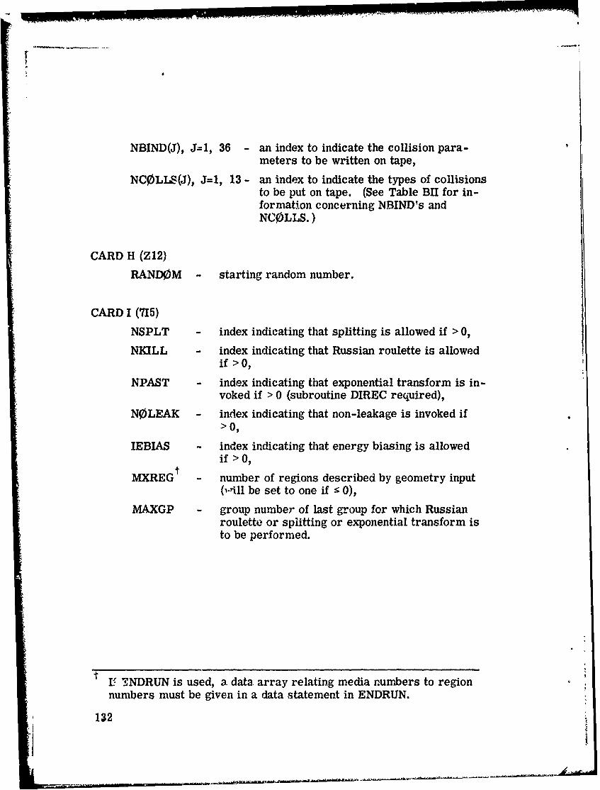
NBIND(J), J=l, 36 - an index to indicate the collision para-meters to be written on tape,
NC0LLS(J), J=l, 13 - an index to indicate the types of collisionsto be put on tape. (See Table BIU for in-formation concerning NBIND's andNCOLLS.)
CARD H (Z12)
RANDOM - starting random number.
CARD I (715)
NSPLT - index indicating that splitting is allowed if > 0,
NKILL - index indicating that Russian roulette is allowedif > 0,
NPAST - index indicating that exponential transform is in-voked if > 0 (subroutine DIREC required),
NOLEAK - index indicating that non-leakage is invoked if>0,
IEBIAS - index indicating that energy biasing is allowedif >0,
tMXREG - number of regions described by geometry input
(will be set to one if r 0),
MAXGP - group number of last group for which Russianroulette or spiitting or exponential transform isto be performed.
tI FNDRUN is used, a. data. array relating media numbers to region
numbers must be given in a data statement in ENDRUN.
132
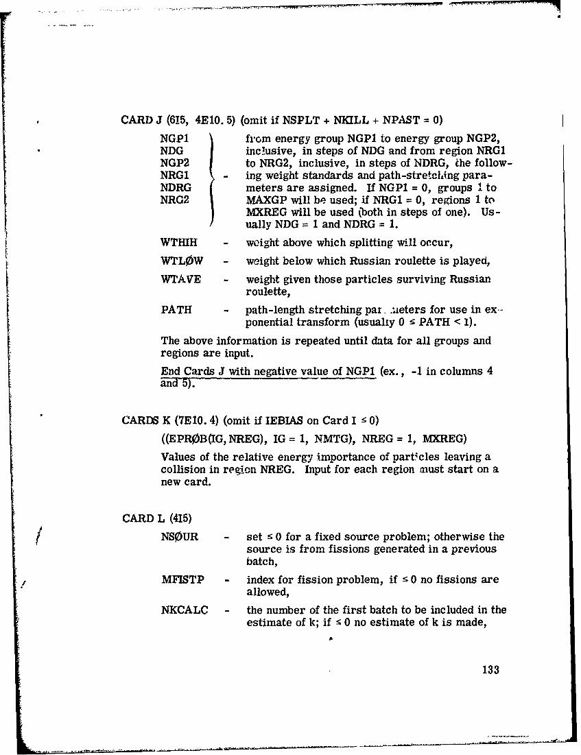
CARD J (615, 4E10. 5) (omit if NSPLT + NKILL + NPAST = 0)
NGPI from energy group NGP1 to energy group NGP2,NDG inc!usive, in steps of NDG and from region NRG1NGP2 to NRG2, inclusive, in steps of NDRG, the follow-NRGI - ing weight standards and path-stretching para-NDRG meters are assigned. If NGP1 = 0, groups I toNRG2 MAXGP will be used; if NRGI = 0, regions 1 to
MXREG will be used (both in steps of one). Us -ually NDG = 1 and NDRG = 1.
WTHIH - weight above which splitting will occur,
WTLOW - weight below which Russian roulette is played,
WTAVE - weight given those particles surviving Russianroulette,
PATH - path-length stretching par .. ieters for use in ex-ponential transform (usually 0 - PATH < 1).
The above information is repeated until data for all groups andregions are input.
End Cards J with negative value of NGP1 (ex., -1 in columns 4and 5).
CARDS K (7E 10. 4) (omit if IEBIAS on Card I ! 0)
((EPR0B(IG, NREG), IG = 1, NMTG), NREG = 1, MXREG)
Values of the relative energy importance of particles leaving acollision in region NREG. Input for each region miust start on anew card.
CARD L (415)
NS0UR set : 0 for a fixed source problem; otherwise thesource is from fissions generated in a previousbatch,
MFISTP - index for fission problem, if - 0 no fissions areallowed,
NKCALC - the number of the first batch to be included in theestimate of k; if ! 0 no estimate of k is made,
133

N0RMF the weight standards and fission weights are un-changed if ! 0; otherwise fission weights will bemultiplied, at the end of each batch, by the latestestimate of k and the weight otandards are mul-tiplied by the ratio of fission weights produced inprevious batch to the average starting weight forthe previous batch. For time-dependent decay-ing systems, N0RMF should be > 0.
CARDS M (7E10. 4) (omit if MFISTP on Card L :5 0)
(FWL)(I), I = 1, MXREG) values of the weight to be assigned tofission neutrons.
CARDS N (7E10. 4) (omit if MFISTP on Card L < 0)
(FSE(IG, IMED), IG = 1, NMGP), IMED = 1, MEDIA) the fractionof fission-induced source particles in group IG and medium IMED.
Note: Input for each medium must start on a new card.
CARDS 0 (7E10. 5) (omit if NGPQTN = 0 or NGPQTG = 0, i. e., includeif coupled neutron-gamma-ray problem)
((GWLO(IG, NREG), IG = 1, NMGP or NMTG - NMGP), NREG = 1,MXREG) average number of secondary particles to be
generated. NMGP groups are read for eachregion in a forward problem and NM'c'G -NMGP for an adjoint. Input for each regionmust start on a new card.
134

TABLE BI.
Sample Group Input Numbers for SomeRepresentative Problems*
Case A - Neutron Only Cross Sections (22 groups)Case B - Gamma-Ray Onlv Cross Sections (18 groups)Case C - Neutron-Gamma-Ray-Coupled Cross Sections (22-18 groups)
Problem Type
00 to >. 0 0 .C
0 "d
~z 0
Input Variable L z ZE-4 UOH UZ ZE-4 E• 4
MORSE Input:
NGPQTN 14 0 14 0 14
NGPQTG 0 17 0 17 17 CARD B,
NMGP 22 18 22 18 22 Variables
NMTG 22 18 22 18 40
NGP 22 18 22 0 22
NGG 0 0 0 18 18 CARDXB
INGP 22 18 40 40 40 Variables
For cross sections with full downscatter, NDS = NGP, NDSG = NGG,INDS = xNGP, and ITBL = number of downscatters + number of up-scatters + 3. Usually, ISGG = number of upscatters + 4.
135

TABLE B1i.
BANKR Arguments (NCOLLS)
BANKR CalledArgument from Location of Call in Walk
-1 MORSE After call to INPUT--to set parametersfor new problem
-2 MORSE At the beginning of each batch of NSTRTparticles
-3 MORSE At the end of each batch of NSTRTparticles
-4 MORSE At the end of each sot of NITS batches--a new problem is about to begin
1 MSOUR After a source event
2 TESTW After a splitting has occurred--com-mented in cohlmn 1
3 FPR,;B After a firsion has occurred
4 GSTORE After a secondary particle has beengenerated
5 MORSE After a real collision has occurred--post-collision parameters are avail-able
6 MORSE After an albedo collision has occurred--post-collision parameters are available
7 NXTCOL After a boundary crossing occurs (thetrack has encountered a new geometrymedium other than the albedo or voidmedia)
8 NXTCOL After an escape occurs (the geometryhas encountered medium zero)
9 MORSE After the post-collision energy groupexceeds the maximum desired--corn-mented in column I
136

TABLE B1l. (Cont'd.)
BANKR CalledArgument from Location of Call in Walk
10 MORSE After the maximum chronological agehas been exceeded--commented incolumn I
11 TESTW After a Russian roulette kill occurs--commented in column I
12 TESTW After a Russian roulette survival
occurs -- commented in column I
13 GSTORE After a secondary particle has beengenerated but no room in the bank isavailable--commented in column 1.
137
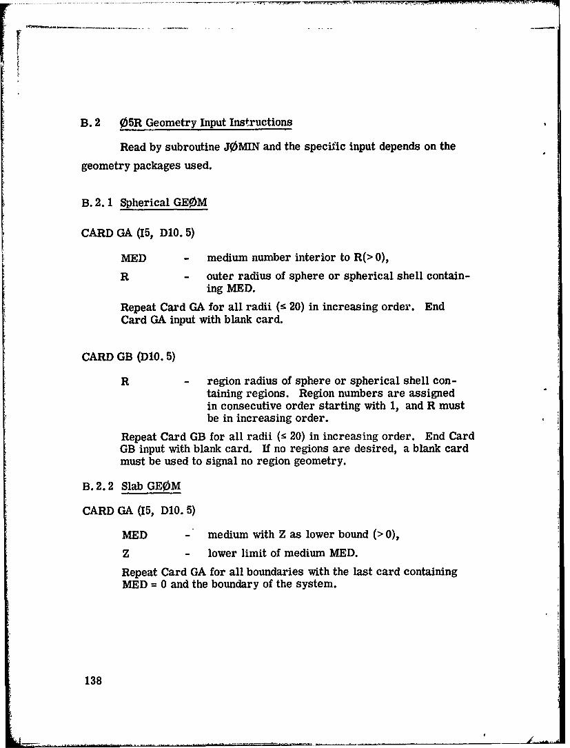
B. 2 05R Geometry Input Instructions
Read by subroutine J0MIN and the specific input depends on the
geometry packages used.
B. 2. 1 Spherical GE0M
CARD GA (15, D1O. 5)
MED - medium number interior to R(> 0),
R - outer radius of sphere or spherical shell contain-ing MED.
Repeat Card GA for all radii (r 20) in increasing order. EndCard GA input with blank card.
CARD GB (DIO. 5)
R - region radius of sphere or spherical shell con-taining regions. Region numbers are assignedin consecutive order starting with 1, and R mustbe in increasing order.
Repeat Card GB for all radii (r 20) in increasing order. End CardGB input with blank card. If no regions are desired, a blank cardmust be used to signal no region geometry.
B. 2.2 Slab GE0M
CARD GA (15, D1O. 5)
MED - medium with Z as lower bound (> 0),
Z - lower limit of medium MED.
Repeat Card GA for all boundaries with the last card containingMED = 0 and the boundary of the system.
138
CARD GB (D1O. 5)
Z lower limit of region boundary. Region numbersare assigned in consecutive order starting with1, and Z must be in increasing order.
Repeat Card GB for all region boundaries.
End Card GB input with a blank card. If no region geometry isdesired, a blank card is required.
CARD GC (4D/0. 5)
XL - lower boundary of system in X direction,
XU - upper boundary of system in X direction,
YL - lower boundary of system in Y direction,
YU - upper boundary of system in Y direction.
B. 2.3 Cylindrical GE0M
CARD GA (15, 5X, A8)
NREGIN - flag to indicate material media (=2) or bothregion and material media (=1),
SEX - sex of programmer.
CARD GB (ElO. 5)
R - radii of the cylindrical shells describing the
material media in ascending order.
"Repeat Card GB until all radii have been input.
End Card GB input with a blank card.
139
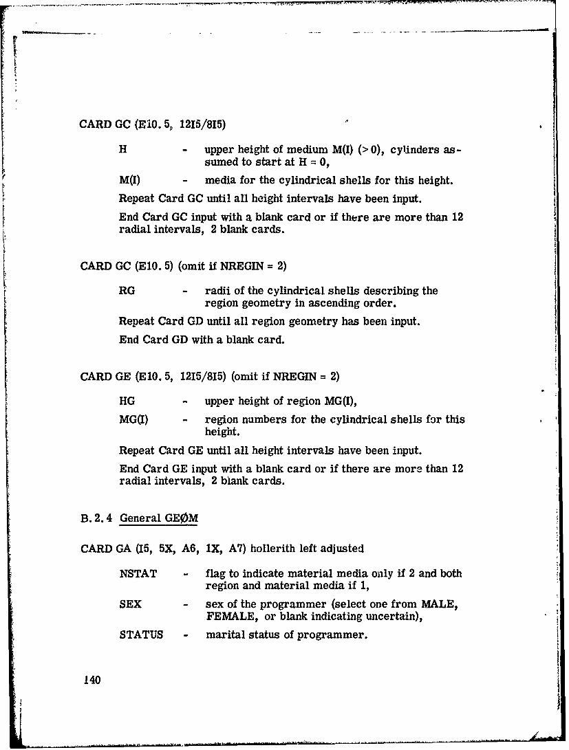
CARD GC (E10. 5, 1215/815)
H - upper height of medium M(I) (> 0), cylinders as-sumed to start at H = 0,
M(I) - media for the cylindrical shells for this height.
Repeat Card GC until all height intervals have been input.
End Card GC input with a blank card or if there are more than 12radial intervals, 2 blank cards.
CARD GC (El0. 5) (omit if NREGIN = 2)
RG - radii of the cylindrical shells describing theregion geometry in ascending order.
Repeat Card GD until all region geometry has been input.
End Card GD with a blank card.
CARD GE (ElO. 5, 1215/815) (omit if NREGIN = 2)
HG - upper height of region MG(I),
MG(I) - region numbers for the cylindrical shells for thisheight.
Repeat Card GE until all height intervals have been input.
End Card GE input with a blank card or if there are more than 12radial intervals, 2 blank cards.
B. 2.4 General GE0M
CARD GA (15, 5X, A6, IX, A7) hollerith left adjusted
NSTAT - flag to indicate material media only if 2 and bothregion and material media if 1,
SEX - sex of the programmer (select one from MALE,FEMALE, or blank indicating uncertain),
STATUS - marital status of programmer.
140
1I
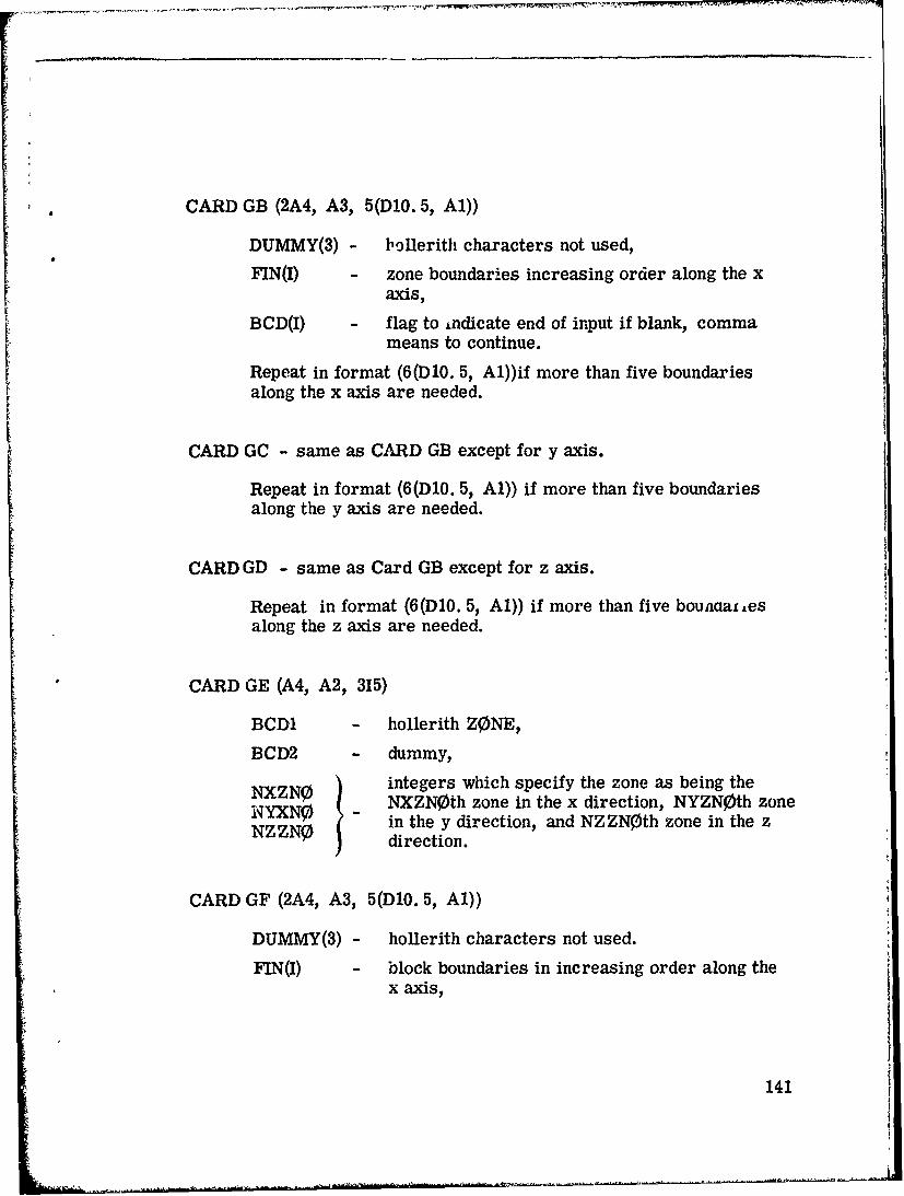
CARD GB (2A4, A3, 5(DIO. 5, Al))
DUMMY(3) - bollerith characters not used,
FIN(I) - zone boundaries increasing order along the xaxis,
BCD(I) - flag to indicate end of input if blank, commameans to continue.
Repeat in format (6(D10. 5, A1))if more than five boundariesalong the x axis are needed.
CARD GC - same as CARD GB except for y axis.
Repeat in format (6(D1O. 5, Al)) if more than five boundariesalong the y axis are needed.
CARD GD - same as Card GB except for z axis.
Repeat in format (6(D1O. 5, Al)) if more than five bounaaL~esalong the z axis are needed.
CARD GE (A4, A2, 315)
BCD1 - hollerith ZONE,
BCD2 - dummy,
NXZN0 integers which specify the zone as being theN'YXN0 NXZNoth zone in the x direction, NYZN0th zoneNZZN0 ( in the y direction, and NZZNOth zone in the z
Z direction.
CARD GF (2A4, A3, 5(D1O. 5, Al))
DUMMY(3) - hollerith characters not used.
FIN(I) - block boundaries in increasing order along thex axis,
141

BCD(I) flag to indicate end of input if blank, commameans to continue.
Repeat in format (6(D1O. 5, Al)) if more than five boundariesalong the x axis are needed.
CARD GG - same as Card GF except for y axis.
Repeat in format (6(D10. 5, Al)) if more than five boundariesalong the y axis are needed.
CARD GH - same as Card GF except for z axis.
Repeat in 'ormat (6(DlO. 5, Al)) if more than five boundariesalong the z axis are needed.
CARDS GI to Go describe the geometry for a blnck and must be includedfor each block in tne zone.
CARD GI (A4, A2, 315)
BCDI - hollerith BLOC,
BCD2 - dummy,
NXBND integers which specify the block as being theNYBND - NXBNDth in the x direction, the NYBNDfh in theNZBND y direction, and the NZBIND in the z direction.
CARD GJ (3A4, 10(15, Al))
NAM2 - hollerith MEDI,
DUM(2) - dummy,
INP(1) - a list of media sector by sector "n the block,
BCD(I) - flag to indicate end of input if blank, a commameans to continue.
Continuation with 12(15, Al).
142
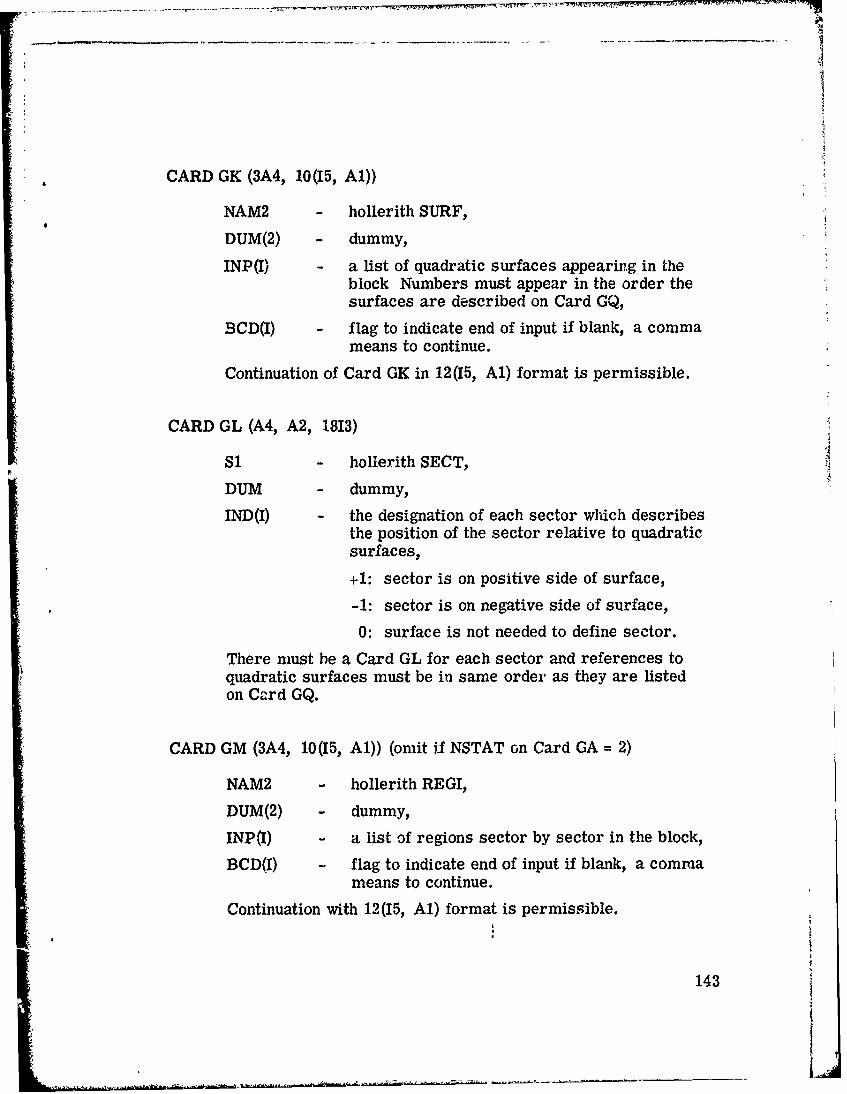
CARD GK (3A4, 10(15, Al))
NAM2 - hollerith SURF,
DUM(2) - dummy,
INP(I) - a list of quadratic surfaces appearing in theblock Numbers must appear in the order thesurfaces are described on Card GQ,
JBCD(I) - flag to indicate end of input if blank, a commameans to continue.
Continuation of Card GK in 12(15, Al) format is permissible.
CARD GL (A4, A2, 1813)
S1 - hollerith SECT,
DUM - dummy,
IND(I) - the designation of each sector which describesthe position of the sector relative to quadraticsurfaces,
+1: sector is on positive side of surface,
-1: sector is on negative side of surface,
0: surface is not needed to define sector.
There must be a Card GL for each sector and references toquadratic surfaces must be in same order as they are listedon Card GQ.
CARD GM (3A4, 10(15, Al)) (omit if NSTAT on Card GA = 2)
NAM2 - hollerith REGI,
DUM(2) - dummy,
INP(1) - a list of regions sector by sector in the block,
BCD(I) - flag to indicate end of input if blank, a commameans to continue.
Continuation with 12(15, Al) format is permissible.
143

CARD GN (3A4, l0(I5, Al)) (omit if NSTAT on Card GA = 2)
NAM2 - hollerith SURF,
DUM(2) - dummy,
INP(I) same as for Card GK except for region input in-BCD(I) stead of mterial input.
CARD GO (A4, A2, 1813) (omit if NSTAT on Card GA = 2)
S1 - hollerith SECT,
DUM - dummy,
IND(I) - same as for Card GL except for region input in-stead of material input.
Repeat\Cards GI to GO for each block.
CARD GP (I5, 16A4, A2)
N0BD - total number of quadratic surfaces in -Ohe entiresystem,
DI'M(I) - hollerith characters ignored by the code. (Help-ful in identifying input at a later time.)
CARD GQ (4 (D1O. 5' A4, lX, Al))
C0F(J) - coefficient of the term,
BCDI(J) - hollerith indicati ,ig which term of the equation.XjQ, YSQ, ZSQ, XZ, YX, YZ, XY, ZX, YZ,X, Y, Z, or blank are the possibilities,.
BCD2(J) - a flag which indicates the quadratic equationcontinues. Any non-blank character ends thefield. The next function -must start on n ýw card,
Repeat Caras GQ until all surfaces have been described.
A saziple of the input is shown in Table BMI.
144
----- I
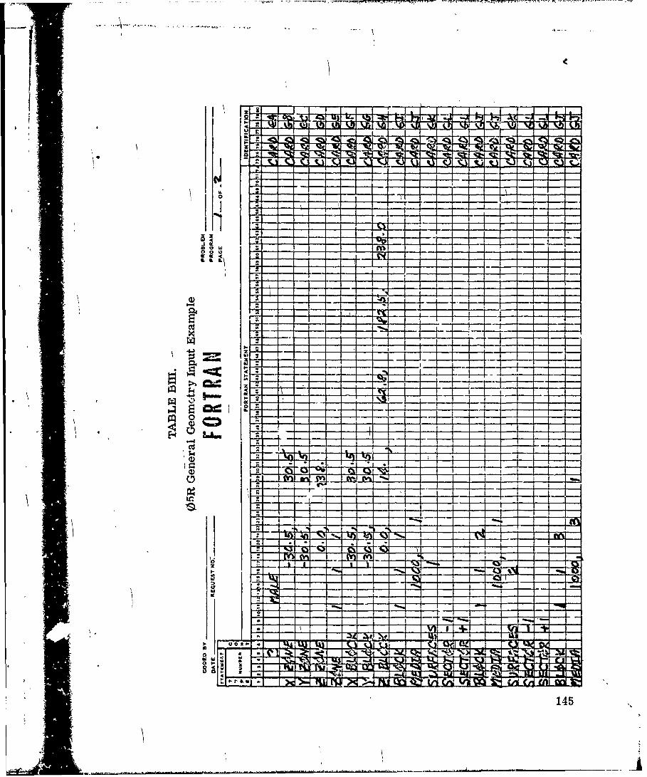
I P
44
I14

VI
hIm
1466
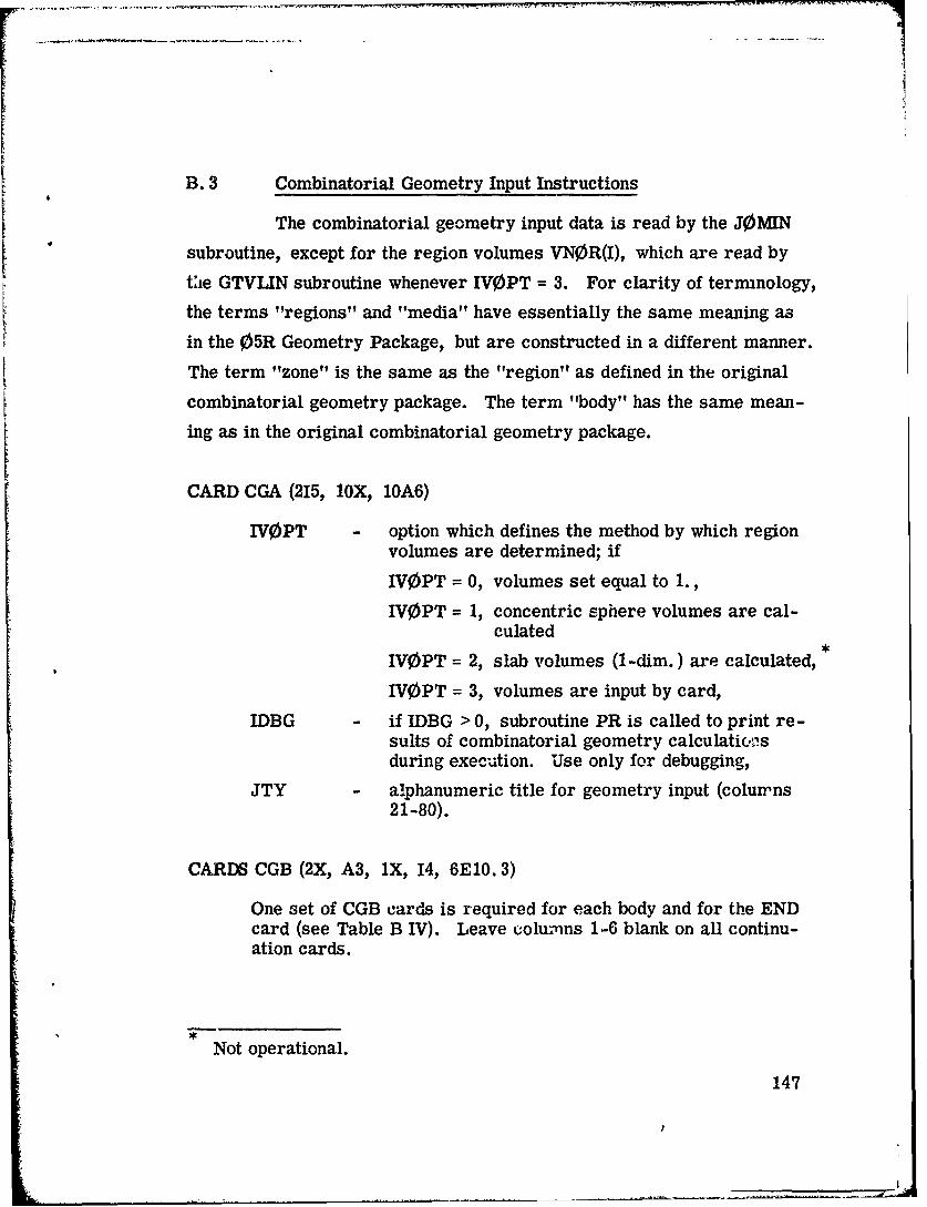
B. 3 Combinatorial Geometry Input Instructions
The combinatorial geometry input data is read by the J0MIN
subroutine, except for the region volumes VNOR(I), which are read by
tie GTVLIN subroutine whenever IV0PT = 3. For clarity of terminology,
the terms "regions" and "media" have essentially the same meaning as
in the 05R Geometry Package, but are constructed in a different manner.
The term "zone" is the same as the "region" as defined in the original
combinatorial geometry package. The term "body" has the same mean-
ing as in the original combinatorial geometry package.
CARD CGA (215, lOX, 10A6)
IVOPT option which defines the method by which region
volumes are determined; if
IVOPT = 0, volumes set equal to 1.,
IVOPT = 1, concentric sphere volumes are cal-culated
IVOPT = 2, slab volumes (1-dim.) are calculated,
IVOPT = 3, volumes are input by card,
IDBG if IDBG > 0, subroutine PR is called to print re-sults of combinatorial geometry calculation'sduring execution. Use only for debugging,
JTY alphanumeric title for geometry input (columrns21-80).
CARDS CGB (2X, A3, 1X, 14, 6E10. 3)
One set of CGB cards is required for each body and for the ENDcard (see Table B IV). Leave columns 1-6 blank on all continu-ation cards.
Not operational.
147

ITYPE specifies body type or END to terminate readingof body data (for example BOX, RPP, ARB, etc.).Leave blank for continuation cards,
IALP body number assigned by user (all input bodynumbers must form a sequence set beginning at1). If left blank, numbers are assigned sequen-tially. Either assign all or none of the numbers.Leave blank for continuation cards,
FPD(I) real data required for the given body as shownin Table B IV.
CARDS CGC (2X, A3, 15, 9(A2, 15))
Input zone specification cards. One set of cards required foreach input zone, with input zone numbers being assigned sequen-tially.
IALP IALP must be a nonblank for the first card ofeach set of cards defining an input zone. IfIALP is blank, this card is treated as a con-tinuation of the previous zone card,
IALP = END denotes the end of zone description.
NAZ total number of zones that can be entered uponleaving any of the bodies defined for this inputregion (some zones may be counted more thanonce). Leave blank for continuation cards for agiven zone. (If NAZ : Oon the first card of thezone card set, then it is set to 5). This is usedto allocate blank common,
Alternate IIBIAS(I) and JTY(I) for all bodies de-fining this input zone.
IIBIAS(I) - specify the "OR" operator if required for theJTY(I) body,
JTY(I) - body number with the (+) or (-) sign as requiredfor the zone description
148

CARDS CGD (1415)
MRIZ(I) - MRIZ(I) is the region number in which the "Iinput zone is contained (I = 1, to the number ofinput zones). Region numbers must be sequen-tially defined from 1.
CARDS CGE (1415)
MMIZ(I) MMIZ(1) is the medium number in which the,Ith,' input zone is contained (I = 1, to the
number of input zones). Medium numbers mustbe sequentially defined from 1.
CARDS CGF (7E10. 5) (omit if IV0PT J 3)
VN0R(I) - volume of the ,Ith'l region (I = 1 to MXREG, thenumber of regions).
Note: If ENDRUN is used to obtain collision density and tracklength per unit volume estimate of fluence, then a datastatement in ENDRUN must give a relationship betweenregion and media. In this case only one medium may bein a region.
149
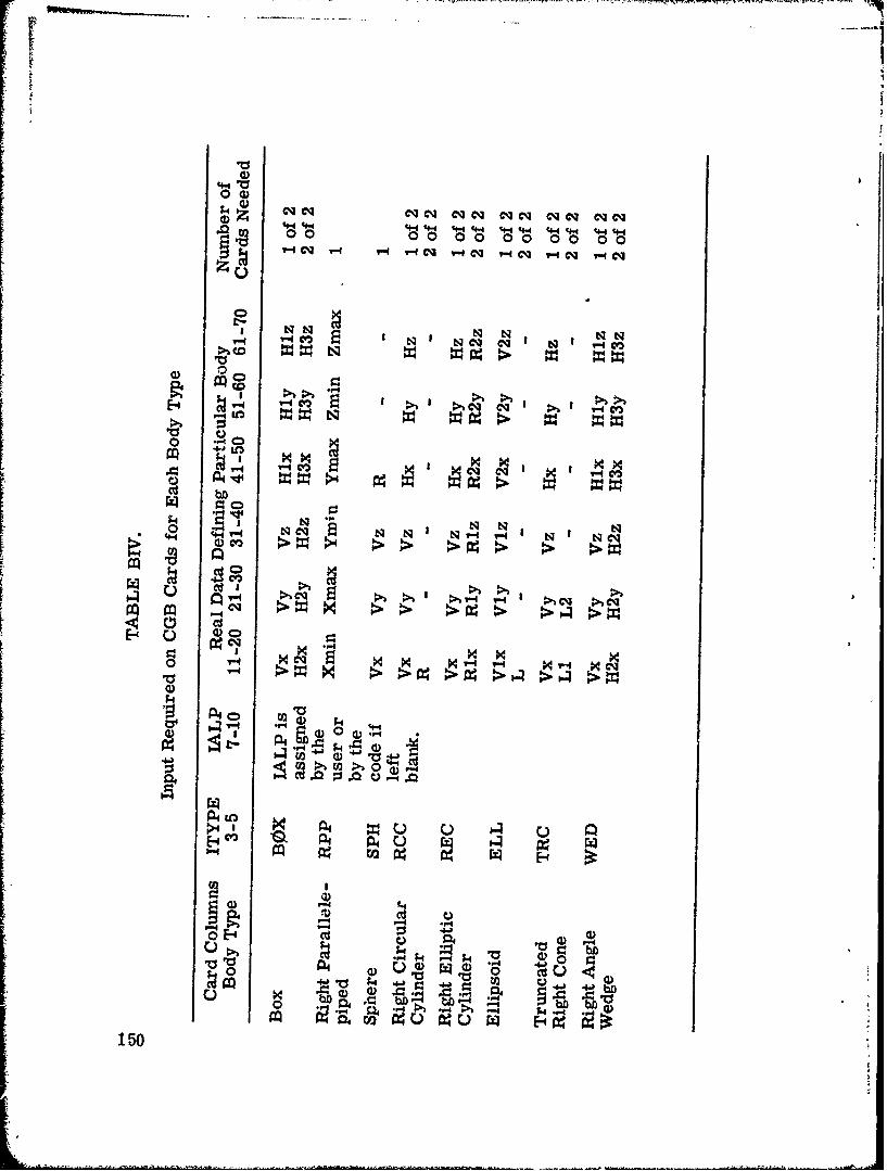
t0
z * 44 cq CM ~cq cq qcq eq cq eq c000 0 0 0 0 00 00
'-Cv I - 'qT1c y-4 4 '- q V-4 C-Q -q ' .4e eq
a NNV- 4C m N N cq cq~ I Q 1 4
0 0
w ~ '4q~ cqi I
ci bD
4-4 V- N cq N 1 Ny-1 V-1 N
cr)I
V-4 T-~~4 V-4 . q9
0 114 14eq M1 A4-4 MCI
,~ P40 ~ U)4.
E-4& P4 P, u W~~E-4
0 C:
150
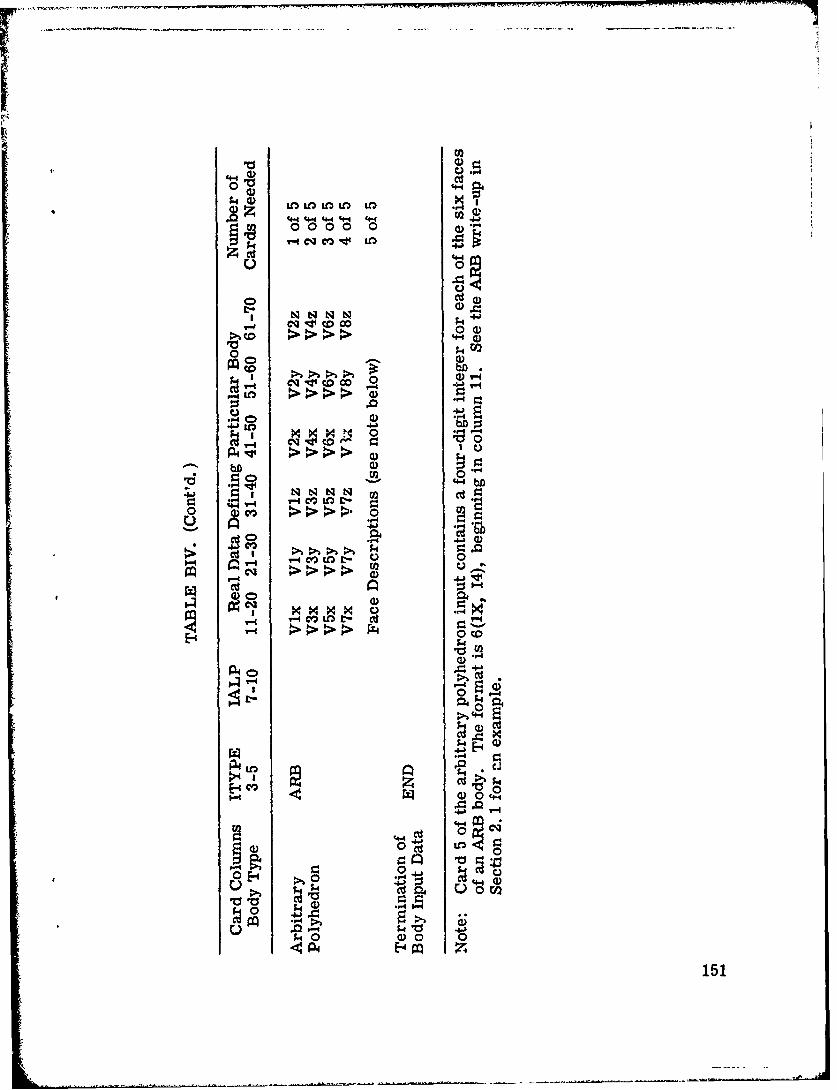
LO~~. U13,..L LCd
0)0
coJ C4.> 4- > 4~ 4-
0v co CO
Lbfl
V 0))0 N~- N -I
I1.4 v- m L r
CD)
..- >NN prC co
r-44 &4 0 4
Cd'dI-P- 4 4 X.
CD 0) 4-
0)
0 E-4 >
Cdd
~0)0-0 0 .,
C4 Cu1 .H4 0

B. 4 M0RSEC- -Cross -Section Module Input Instructions
CARD XA (20A4)
Title card for cross sections. This title is also written on tapeif a processed tape is written; therefore, it is suggested that thetitle be definitive.
CARD XB (1315)
Column Name Description
5 NGP - the number of primary groups for whichthere are cross sections to be stored.Should be same as NMGP input in MORSE,
10 NDS - number of primary downscatters for NGP(usually NGP),
15 NGG - number of secondary groups for which thereare cross sections to be stored,
20 NDSG - number of secondary downscatters for NGG(usually NGG),
25 INGP - total number of groups for which crosssections are to be input,
30 ITBL - table length, i. e., the number of crosssections for each group (usually equal tonumber of downscatters + number of up-scatters + 3),
35 ISGG - location of within-group scattering crosssections (usually equal to number of up-scatters + 4),
40 NMED - number of media for which cross sectionsare to be stored- -should be same as MEDIAinput in MORSE,
45 NELEM - number of elements for which cross sectionsare to be read,
152
:1l

CARD XB (Cont'd.)
Column Name Description
50 NMIX - number of mixing operations (elementstimes density operations) to be performed(must be > 1),
55 NC0EF number of coefficients for each element,including P0O
60 NSCT - number of discrete angles (usuallyNCOEF/ 2 integral),
65 ISTAT - flag to store Legendre coefficients ifgreater than zero.
CARD XC (1115)
Column Name Description
5 IRDSGt - switch to print the cross sections as theyare read iU > 0, if < 0 card sequence is notchecked,
10 ISTRt - switch to print cross sections as they arestored if > 0,
15 IFMUt - switch to print intermediate results of ;I'scalculation if > 0,
20 IMMt - switch to print moments of angular dis-tribution if > 0,
25 IPRIN - switch to print angles and probabilities if>0,
30 IPUNt - switch to print results of bad Legendre co-efficients if > 0,
t35 IDTF - switch to signal that input format is DTF-IV
format if > 0; otherwise, ANISN format isassumed,
Switches are ignored if IXTAPE < 0.
153i
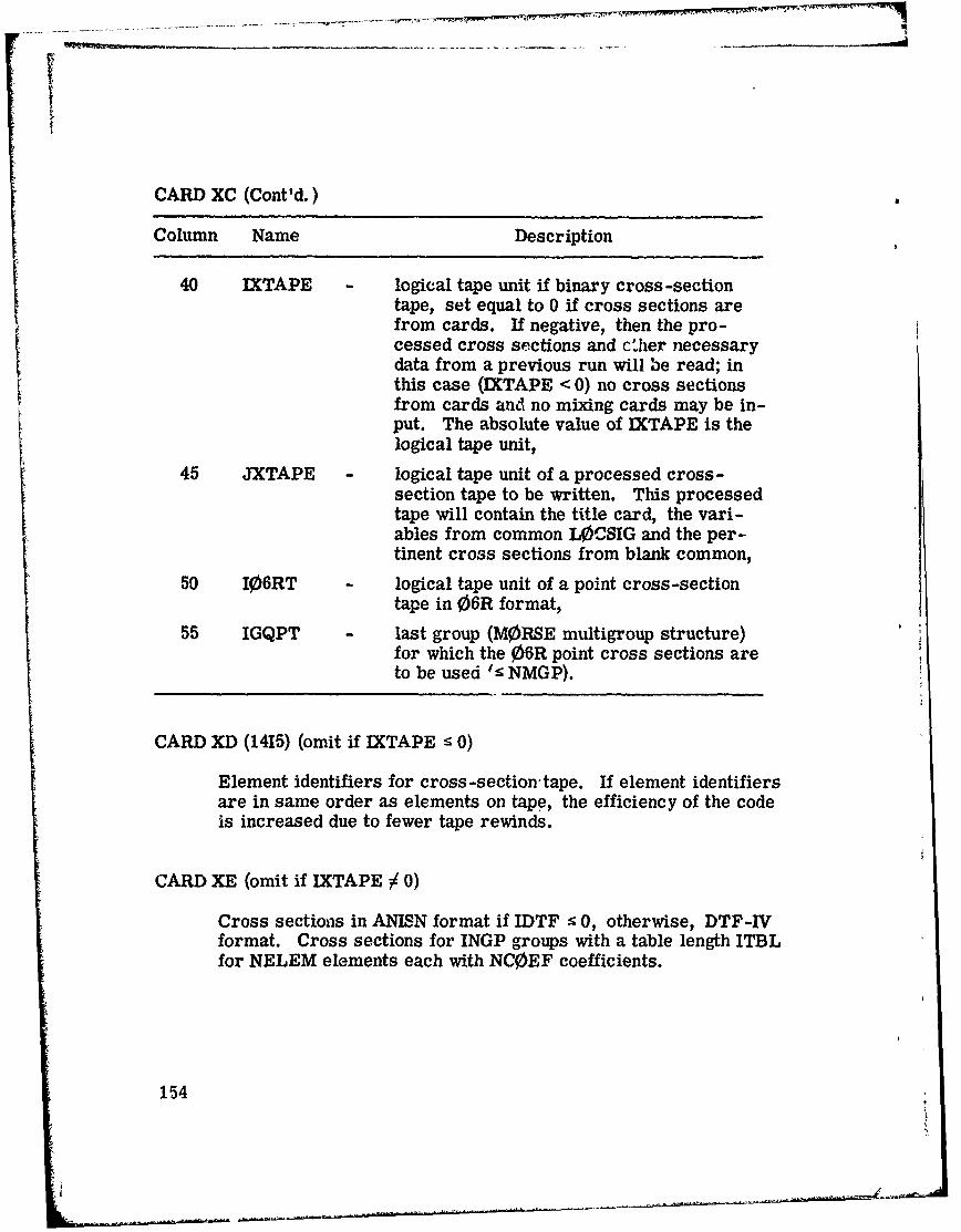
CARD XC (Cont'd.)
Column Name Description
40 IXTAPE - logical tape unit if binary cross -sectiontape, set equal to 0 if cross sections arefrom cards. If negative, then the pro-cessed cross sections and c'her necessarydata from a previous run will be read; inthis case (IXTAPE < 0) no cross sectionsfrom cards and no mixing cards may be in-put. The absolute value of IXTAPE is thelogical tape unit,
45 JXTAPE - logical tape unit of a processed cross -section tape to be written. This processedtape will contain the title card, the vari-ables from common L0CSIG and the per-tinent cross sections from blank common,
50 106RT - logical tape unit of a point cross-sectiontape in 06R format,
55 IGQPT - last group (MORSE multigroup structure)for which the 06R point cross sections areto be used t NMGP).
CARD XD (1415) (omit if IXTAPE : 0)
Element identifiers for cross -section tape. If element identifiersare in same order as elements on tape, the efficiency of the codeis increased due to fewer tape rewinds.
CARD XE (omit if IXTAPE / 0)
Cross sections in ANISN format if IDTF : 0, otherwise, DTF-IVformat. Cross sections for INGP groups with a table length ITBLfor NELEM elements each with NCOEF coefficients.
154
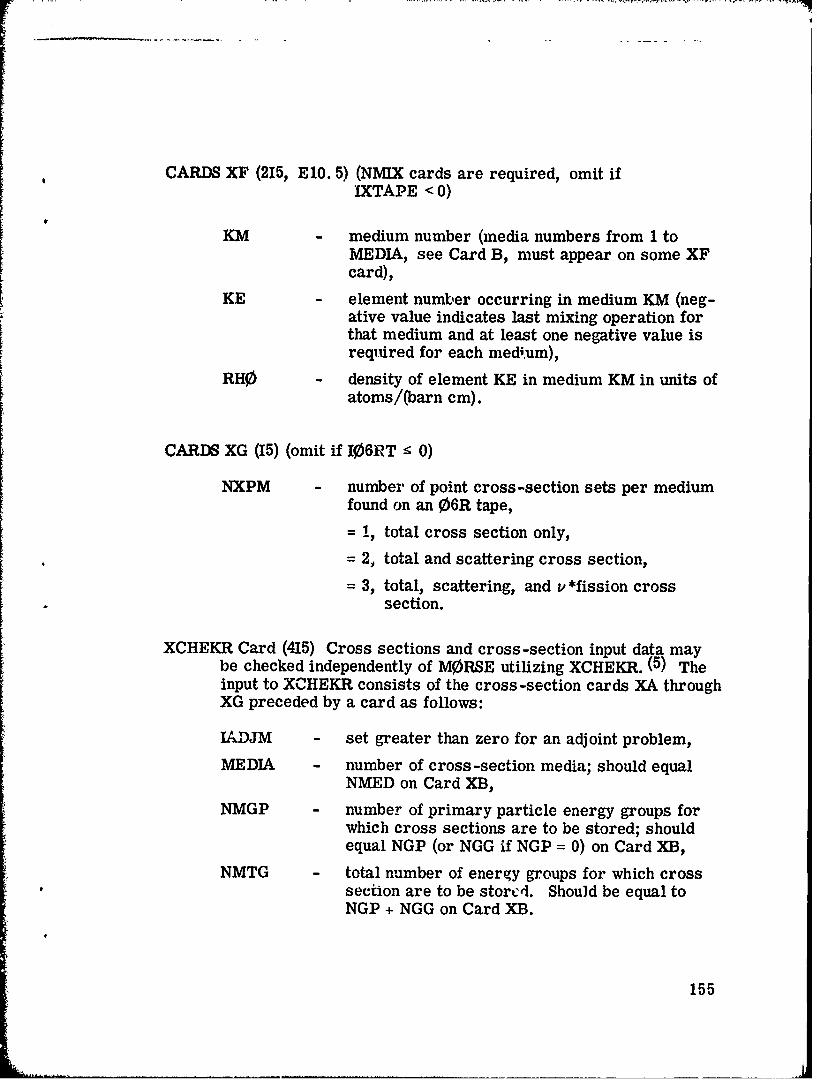
CARDS XF (215, El0. 5) (NMIX cards are required, omit ifIXTAPE < 0)
KM medium number (media numbers from 1 toMEDIA, see Card B, must appear on some XFcard),
KE element number occurring in medium KM (neg-ative value indicates last mixing operation forthat medium and at least one negative value isrequired for each medium),
RHO density of element KE in medium KM in units ofatoms/(barn cm).
CARDS XG (15) (omit if I0610T • 0)
NXPM - number of point cross-section sets per mediumfound on an 06R tape,
= i, total cross section only,
= 2, total and scattering cross section,
= 3, total, scattering, and v *fission crosssection.
XCHEKR Card (415) Cross sections and cross-section input data maybe checked independently of MORSE utilizing XCHEKR. (5) Theinput to XCHEKR consists of the cross -section cards XA throughXG preceded by a card as follows:
IADJM - set greater than zero for an adjoint problem,
MEDIA - number of cross -section media; should equalNMED on Card XB,
NMGP - number of primary particle energy groups forwhich cross sections are to be stored; shouldequal NGP (or NGG if NGP = 0) on Card XB,
NMTG - total number of energy groups for which cross* 'section are to be stored. Should be equal to
NGP + NGG on Card XB.
155

B. 5 SAMB0 Analysis Input Instructions
The following data are read from cards by SC0RIN:
CARD AA (20A4)
Title information -- will be immediately output.
CARD AB (815)
ND - number of detectors (set =1 if e 0),
NNE - number of primary particle energy bins to beused, (must be • NE),
NE - total number of energy bins (set =0 if : 1),
NT - nurmoer of time bins for each detector (may benegative, in which case I NT I values are to beread and used for every detector) (set =0 if'NTI •1),
NA - number of angle bins (set =0 if • 1),
NRESP - number of energy-dependent response functionsto be used (set =1 if s 0),
NEX - number of extra arrays of size NMTG to be setaside (useful, for example, as a place to storean array of group-to-group transfer probabilitiesfor estimator routines. If the subroutineENDRUN which outputs fluence estimates fromcollision and track lengths is used, then thisnumber must be at least MXREG + 2 (see Card Ifor MXREG),
NEXND number of extra arrays of size ND to be setaside (useful, for example, as a place to storedetector -dependent counters).
156
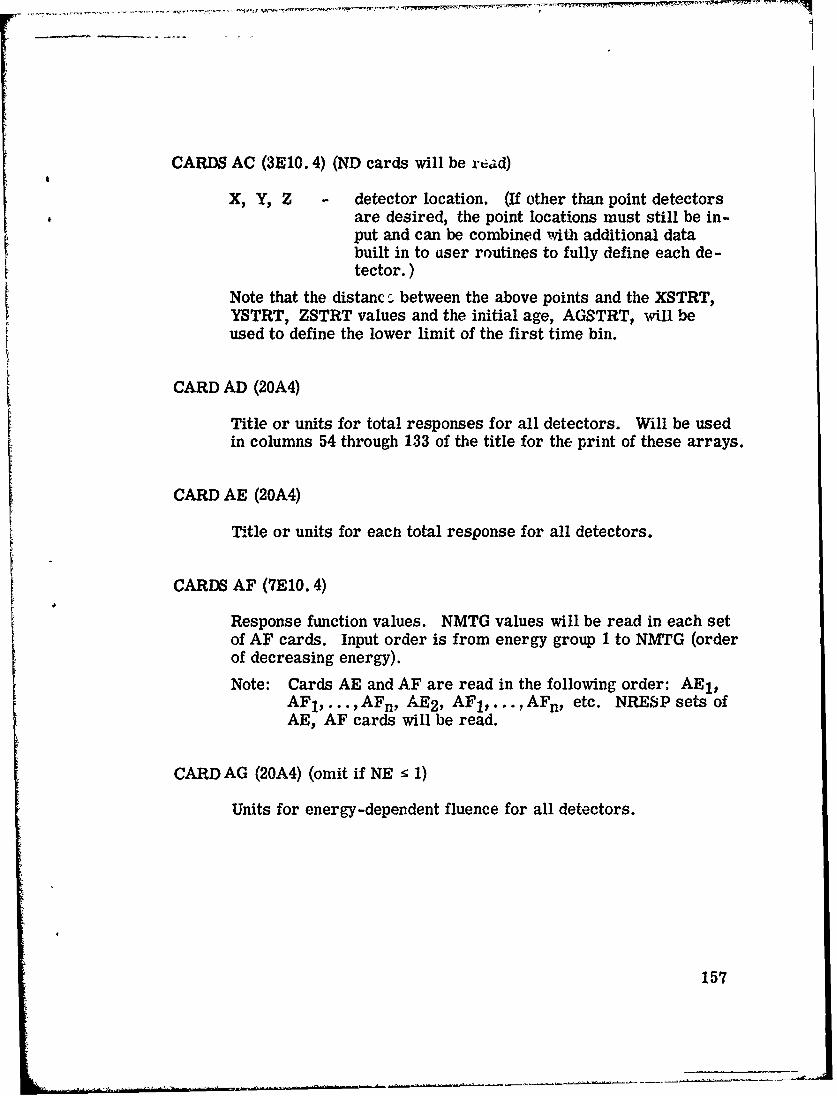
CARDS AC (3E0. 4) (ND cards will be read)
X, Y2 Z - detector location. (If other than point detectorsare desired, the point locations must still be in-put and can be combined with additional databuilt in to user routines to fully define each de-tector.)
Note that the distanc r- between the above points and the XSTRT,YSTRT, ZSTRT values and the initial age, AGSTRT, will beused to define the lower limit of the first time bin.
CARD AD (20A4)
Title or units for total responses for all detectors. Will be usedin columns 54 through 133 of the title for the print of these arrays.
CARD AE (20A4)
Title or units for each total response for all detectors.
CARDS AF (OEl0. 4)
Response function values. NMTG values will be read in each setof AF cards. Input order is from energy group 1 to NMTG (orderof decreasing energy).
Note: Cards AE and AF are read in the following order: AE 1 ,AFI, . . . s AFn, AE 2 , AF 1 , . . . , AFn, etc. NRESP sets ofAE1, AF cards will be read.
CARD AG (20A4) (omit if NE 5 1)
Units for energy-dependent fluence for all detectors.
157

CARDS AH (,415) (omit if NE < 1)
Energy grou-) humbers defilning lower limit of enzergy bins (inorder of increasing group numb)The NNE (if > 0) e-try mustequal NGPQTN; the NE entry must be set to NMGP - NGPQTGfor a combined problem, or else NGPQTG or NGPQTN.
CARD Al (20A4) (omit if INT! 1)
"Units for time-dependent total responses for all detectors.
CARD AJ (20A4) (omit if INTI < 1 or E 1)
Units for time and energy-dependent fluence for all detectors.
CARDS AK (7E0. 4) (omit if I NT I 1)
NT val'-es of upper limits of time bins for each detector (in order4f increasing time and detector number)., The values for eachdetector must start on a new card. I NT • values only are readif NT is negative. They are then used for every detector.
CARD AL (20A4) (omit if NA < 1)
Units for angle- and energy-dependent fluence for all detectors.
CARD AM (7E0. 4) (omit if NA : 1)
NA value.s u; upper limits of angle bins (actually cosine bins;the NAtli value must equal one).
Following the input for the SAMB0 analysis module, input cardsfor user-written routines INSCOR, S0URCE, and -NDTU&N.
I5
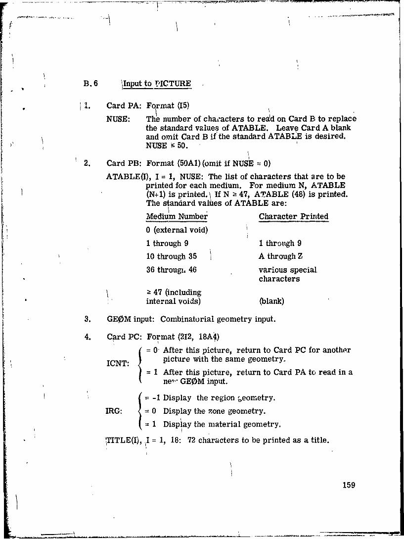
B. 6 'Input to PICTURE
Card PA: Format (15)
NUSE: The number of cha-acters to read on Card B to replacethe standard values of ATABLE. Leave Card A blankand omit Card B if the standard ATABLE is desired.NUSE k 50.
2. Card PB: Format (50A1) (omit if NUSE = 0)ATABLE(I), I = 1, NUSE: The list of characters that are to be
printed for each medium. For medium N, ATABLE(N+1) is printed. \ If N z 47, ATABLE (48) is printed.The standard values of ATABLE are:
Medium Number Character Printed
0 (external void)
1 through 9 1 through 9
10 through 35 A through Z
36 througi. 46 various special.characters
> 47 (includinginternal voids) (blank)
3. GEOM input: Combinatorial geometry input.
4. C~rd PC: Format (212, 18A4)
= 0 After this picture, return to Card PC for another
ICNT: picture with the same geometry.
= 1 After this picture, return to Card PA to read in ane- GE0M input.
S1 Display the region geometry.
IRG: = 0 Display the zone geometry.
= 1 Display the material geometry.
\TITLE(I), I = 1, 18: 72 characters to be printed as a title.
159
- -+---..---/tla~-
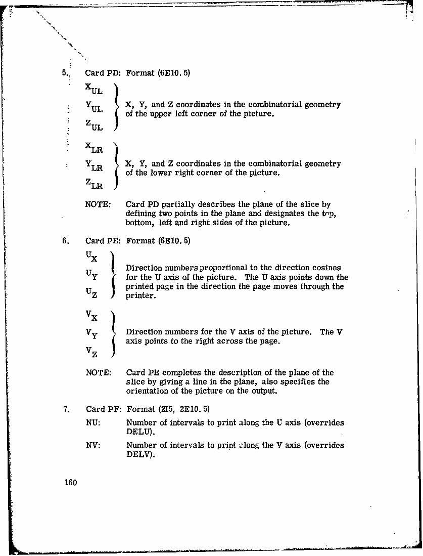
5.. Card PD: Format (6El0. 5)
XUL
U ~X, Y, and Z coordinates in the combinatorial geometryYUL of the upper left corner of the picture.ZUL
XLR
YLR X, Y, and Z coordinates in the combinatorial geometryof the lower right corner of the picture.
Z LR
NOTE: Card PD partially describes the plane of the slice bydefining two points in the plane and designates the top,bottom, left and right sides of the picture.
6. Card PE: Format (6E10. 5)
UX ) Direction numbers proportional to the direction cosinesUY for the U axis of the picture. The U axis points down the
printed page in the direction the page moves through theUz printer.
Vy Direction numbers for the V axis of the picture. The Vaxis points to the right across the page.
Vz
NOTE: Card PE completes the description of the plane of theslice by giving a line in the plane, also specifies theorientation of the picture on the output.
7. Card PF: Format (215, 2El0. 5)
NU: Number of intervals to print along the U axis (overridesDELU).
NV: Number of intervals to print olong the V axis (overridesDELV).
160

DELU: Spacing %.n GEOM units) of intervals along the U axis.
DELV: Spacing (in GEOM units) of intervals along the V axis.
NOTE: All four entries are not required as input on Card PF,see below for explanation.
Options:
X =Y Z =0.LR LR LR
For this case NU and NV must ba specified. In addition, eitherDELU or DELV must be specified. If the other is left blank, thecode will produce an undistorted picture. If both DELU and DELVare specified the picture is likely to be distorted. TI: , standardprinters give 10 characters to the inch across a line but only 6lines per inch down the page. Because of this DELV =. 6*DELUis necessary to produce an undistorted picture.
2. XLR or YLR or ZLR 10.
If any one variable on Card PD is specified, the code will calculatethe othieir to produce an undistorted picture.
If both NU and DELU (or both NV and DELV) are specified, DELU(or DELV) will be ignored.
The U and V axes may have arbitrary orientation. (If they are notorthogonal, the resulting picture will be distorted.) In Option 1,the first point will be at (X, Y, Z)UL, and the remaining points inthe directions and at the distances specified. In Option 2, therange from XUL to XLR is 3'-vided into intervals and the calcu-lated points will be at the rn.dpoints of the intervals. The firstpoint will be 1/2 interval past (X, Y, Z)UL and the final point willbe within 1/2 interval of (X, Y, Z)LR. If (X, Y, Z)LR does notlie on the U-V plane, or if the U and V axes are not orthogonal,the location of the final point is not readily predictable.
The simplest method to obtain the correct results is to specify twodiagonal corners of the plane of the slice on Card PD, with the tophaving the short dimension, if it is not square, and the side havingthe long dimension. Then, on Card PE, specify the U axis to beparallel to the edge of the slice with the large dimension (left or
161

right side), and the V axis to be parallel to the edge of the slicewith the small dimension (top or bottom). Finally, let the onlyentry on Card PF be NV equal to maximum number of charactersper line on your printer, this will provide the largest undistortedpicture.
162
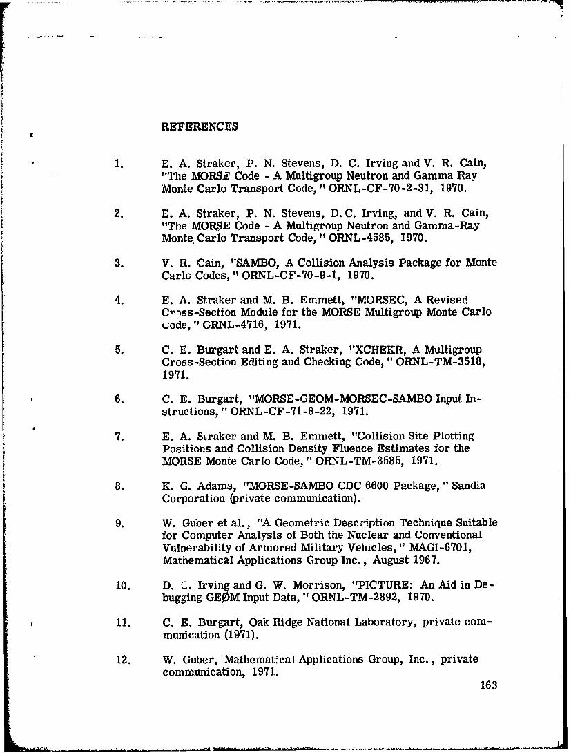
REFERENCES
1. E.A. Straker, P. N. Stevens, D. C. Irving and V. R. Cain,"The MORSE Code - A Multigroup Neutron and Gamma RayMonte Carlo Transport Code," ORNL-CF-70-2-31, 1970.
2. E. A. Straker, P. N. Stevens, D.C. Irving, and V. R. Cain,"The MORSE Code - A Multigroup Neutron and Gamma-RayMonte Carlo Transport Code, " ORNL-4585, 1970.
3. V. R. Cain, "SAMBO, A Collision Analysis Package for MonteCarlo Codes," ORNL-CF-70-9-1, 1970.
4. E. A. Straker and M. B. Emmett, "MORSEC, A RevisedCr-vss-Section Module for the MORSE Multigroup Monte Carlok;ode, " ORNL-4716, 1971.
5. C. E. Burgart and E. A. Straker, "XCHEKR, A MultigroupCross-Section Editing and Checking Code," ORNL-TM-3518,1971.
6. C. E. Burgart, "MORSE-GEOM-MORSEC-SAMBO Input In-structions," ORNL-CF-71-8-22, 1971.
7. E. A. Straker and M. B. Emmett, "Collision Site PlottingPositions and Collision Density Fluence Estimates for theMORSE Monte Carlo Code," ORNL-TM-3585, 1971.
8. K. G. Adams, "MORSE-SAMBO CDC 6600 Package, "SandiaCorporation (private communication).
9. W. Guber et al., "A Geometric Description Technique Suitablefor Computer Analysis of Both the Nuclear and ConventionalVulnerability of Armored Military Vehicles, " MAGI-6701,Mathematical Applications Group Inc., August 1967.
10. D. I. Irving and G. W. Morrison, "PICTURE: An Aid in De-bugging GE0M Input Data, "ORNL-TM-2892, 1970.
11. C. E. Burgart, Oak Ridge National Laboratory, private com-munication (1971).
12. W. Guber, Mathemat.cal Applications Group, Inc., privatecommunication, 1971.
163


![Applications of the Combinatorial Nullstellensatznagyzoli.web.elte.hu/Thesis.pdfcombinatorial geometry [20], finite geometry [19, 56, 82, 91], graph theory [5, 53] and extremal set](https://static.fdocuments.in/doc/165x107/5f1057787e708231d448a1ee/applications-of-the-combinatorial-nul-combinatorial-geometry-20-inite-geometry.jpg)