THE MODELLING OF PROCESSING CONDITIONS FOR …eprints.uthm.edu.my/7791/1/MOHD_HILMI_OTHMAN.pdf ·...
48
THE MODELLING OF PROCESSING CONDITIONS FOR POLYPROPYLENE- NANOCLAY INTEGRAL HINGES AT HIGH HEAT EXPOSURE MOHD HILMI OTHMAN A thesis submitted in fulfilment of the requirement for the award of the Doctor of Philosophy. Faculty of Mechanical and Manufacturing Engineering Universiti Tun Hussein Onn Malaysia MEI 2015
Transcript of THE MODELLING OF PROCESSING CONDITIONS FOR …eprints.uthm.edu.my/7791/1/MOHD_HILMI_OTHMAN.pdf ·...

THE MODELLING OF PROCESSING CONDITIONS FOR POLYPROPYLENE-
NANOCLAY INTEGRAL HINGES AT HIGH HEAT EXPOSURE
MOHD HILMI OTHMAN
A thesis submitted in
fulfilment of the requirement for the award of the
Doctor of Philosophy.
Faculty of Mechanical and Manufacturing Engineering
Universiti Tun Hussein Onn Malaysia
MEI 2015

v
ABSTRACT
This research is about generating models of injection moulding processing conditions,
towards quality performance of polypropylene-nanoclay integral hinges, exposed to
high heat temperature. The assessment of hinges’ quality performance analyses was
translated as the signal to noise ratio values for ultimate tensile strength, shrinkage and
warpage. This research had adopted Taguchi Optimisation Method, to optimise the
processing conditions, to generate the regression models and to construct master
curves for quality performance prediction based on nanoclay content. According to the
results, 18 regression models have been successfully generated. 3 types of master
curves have been constructed based on the produced models with the specific nanoclay
content. Additionally, the quality performance of the integral hinges was extended to
high heat exposures, and the additional of nanoclay had produced a significant
advancement in the injected mould samples. Validation test has been carried out
towards the regression model with most of the models have produced good predictions
of quality performances. The novelty of this research is the correlations between the
optimum injection moulding processing conditions with the precise range of
shrinkage, warpage and ultimate tensile strength. The correlations were simplified in
the form of regression models and master curves. These models and master curves
were recommended as references and a prediction method, specifically for
polypropylene-nanoclay integral hinges manufacturing and design process. These
findings will lead to wider and optimum applications of thin layer parts and
components such as packaging products; as well as other manufacturing field such as
artificial human parts development and building appliances.

vi
ABSTRAK
Kajian ini adalah mengenai penjanaan model keadaan pemprosesan bagi proses acuan
suntikan; terhadap prestasi kualiti engsel bersepadu polipropelina-tanah liat nano yang
terdedah pada suhu tinggi.Penilaian analisis prestasi kualiti ini diterjemahkan melalui
nilai-nilai nisbah isyarat terhadap hingar bagi kekuatan tegangan muktamad,
pengecutan dan perlengkungan. Kajian ini telah mengguna pakai Kaedah
Pengoptimuman Taguchi, untuk mengoptimumkan keadaan pemprosesan, untuk
menjana model regresi dan untuk membangunkan keluk induk bagi prestasi kualiti
berdasarkan kandungan tanah liat nano. Berdasarkan kepada keputusan yang
diperolehi, 18 model regresi telah dijana. 3 jenis keluk induk telah dibangunkan
berdasarkan model yang dihasilkan, mengikut kandungan tanah liat nano yang khusus.
Sebagai tambahan, prestasi kualiti engsel bersepadu ini diperluaskan kepada
pendedahan terhadap suhu yang tinggi, dengan penambahan tanah liat nano yang
mampu menghasilkan kemajuan nilai terhadap sampel acuan suntikan. Ujian
pengesahan telah dijalankan ke atas model regresi dan kebanyakan model
menghasilkan ramalan prestasi kualiti yang baik. Keunikan penyelidikan ini adalah
korelasi antara keadaan pemprosesan acuan suntikan yang optimum dengan julat nilai
yang jitu bagi pengecutan, perlengkungan dan kekuatan tegangan muktamad. Kolerasi
ini telah diterjemahkan dalam bentuk model regresi dan keluk induk, yang mana hasil
dapatan ini sangat dicadangkan sebagai rujukan dan kaedah ramalan, khusus untuk
proses pembuatan dan rekabentuk engsel bersepadu dari polipropelina-tanah liat nano.
Penemuan ini akan membawa kepada aplikasi yang lebih luas dan optimum bagi
pembuatan bahagian-bahagian dan komponen berlapisan nipis, seperti produk
pembungkusan dan juga bidang pembuatan lain seperti pembangunan anggota tiruan
manusia dan peralatan pembinaan.
vii
CONTENTS
TITLE i
DECLARATION ii
DEDICATION iii
ACKNOWLEDGEMENT iv
ABSTRACT v
LIST OF TABLES x
LIST OF FIGURES xii
LIST OF SYMBOLS AND ABBREVIATIONS xiv
LIST OF APPENDICES xvii
CHAPTER 1 INTRODUCTION 1
1. 1 Background study 1
1. 2 Problem statement 2
1. 3 Objectives 3
1. 4 Scope of study 3
1. 5 Expected result 4
CHAPTER 2 LITERATURE REVIEW 5
2. 1 Introduction 5
2.1.1 Injection moulding processing conditions 5
2.1.2 Mould for injection moulding 6
2.1.3 Simulation in injection moulding 8
2.1.4 The effect of processing conditions 11
2.1.5 Optimisation method 14
2. 2 Polypropylene- nanoclay nanocomposites 19
2.2.1 Micro mechanism, structure, morphology
and properties. 20
2.2.2 Preparation methods 23

viii
2.2.3 Clay content and compatibilizers 25
2. 3 Integral hinges design and applications. 30
2. 4 High heat exposure properties of polypropylene. 34
2. 5 Previous research summary 38
CHAPTER 3 METHODOLOGY 40
3. 1 Introduction 40
3. 2 Development of mould 40
3.2.1 Runner size 44
3.2.2 Gate location selection 44
3.2.3 Fabrication and verification of mould. 45
3. 3 Optimisation of processing condition at high heat
exposure 48
3.3.1 Quality performance measurement- Shrinkage,
warpage and ultimate tensile strength. 53
3.3.2 Signal to noise ratio 56
3.3.3 Best combination of processing condition 58
3. 4 Regression modelling 59
3.4.1 Regression model for room temperature 63
3.4.2 Regression model for high temperature
exposure 63
3. 5 Master curves construction. 64
3.5.1 Validation test 65
CHAPTER 4 RESULT AND DISCUSSION 66
4. 1 Introduction 66
4. 2 Development of mould findings 66
4.2.1 Runner size result 69
4.2.2 Gate location results 71
4.2.3 Fabrication and verification of actual mould 75
4. 3 Optimisation of processing condition at high heat
exposure results 79
4.3.1 Warpage results 81
4.3.2 Shrinkage results 83
4.3.3 Ultimate tensile strength results 86

ix
4.3.4 Signal to noise ratio results 90
4.3.5 Best combination of processing condition
at room temperature 91
4.3.6 Best combination of processing condition
at high temperature 92
4. 4 Regression modelling results 94
4.4.1 Quality performance at room temperature 95
4.4.2 Quality performance for high temperature
exposure 96
4. 5 Master curves findings 97
4.5.1. Validation test results 102
4. 6 Summary 103
CHAPTER 5 CONCLUSION AND RECOMMENDATIONS 104
5.1 Conclusion 104
5.2 Recommendations 105
5.1.1 Mould design and development 105
5.1.2 Optimising processing conditions. 106
5.1.3 Product and materials 107
REFERENCES 110
VITA 151

x
LIST OF TABLES
Table 2.1 A review of simulation in injection moulding processes 9
Table 2.2 Summary of simulation area of studies and software 10
Table 2.3 Parameter change versus property effect (Bryce, 1996) 11
Table 2.4 Certain ranges of condition for polypropylene artefacts
(Bauccio et al., 1994). 12
Table 2.5 Previous study about the effects of processing condition 13
Table 2.6 Summary of multiple response optimisations. 19
Table 2.7 Previous researches about clay and compatibilizers 25
Table 2.8 Previous research in polypropylene integral hinges
development via injection moulding. 39
Table 3.1 Initial setup for injection moulding simulation. 43
Table 3.2 Evaluation criteria for mould design. 44
Table 3.3 Runner size test description. 44
Table 3.4 Physical data of AISI D2 (Uddeholm, 2014). 47
Table 3.5 Initial processing condition for actual injection moulding. 47
Table 3.6 Factors and levels selection for practical injection moulding. 48
Table 3.7 Taguchi L9 (34) Orthogonal Array for practical injection moulding. 49
Table 3.8 Thermal properties of the Titanpro 6331 polypropylene
(Lotte Chemical Titan (M) Sdn Bhd., 2014). 49
Table 3.9 Properties of the Cloisite -20A
(BYK Additives &Instruments, 2013). 50
Table 3.10 Formulation of polypropylene-nanoclay nanocomposites. 51
Table 4.1 Cavity filling for Test 1 67
Table 4.2 Cavity filling for Test 2 68
Table 4.3 Result of runner analysis for Test 1 69
Table 4.4 Result of processing conditions based on each design. 71
Table 4.5 Result of warpage and shrinkage based on each mould. 77

xi
Table 4.6 Warpage measurement for 0 wt. % nanoclay specimen 82
Table 4.7 Shrinkage measurement for 0 wt. % nanoclay specimen 85
Table 4.8 Ultimate tensile strength for 0 wt. % nanoclay specimen 87
Table 4.9 Signal to noise ratio for 0 wt. % of nanoclay 90
Table 4.10 Optimum processing condition for room temperature 92
Table 4.11 Optimum processing condition for high temperature condition 93
Table 4.12 The quality performance results at room temperature 97
Table 4.13 The quality performance results at 600C exposure. 99
Table 4.14 The quality performance results at 700C exposure. 101

xii
LIST OF FIGURES
Figure 2.1 Single screw injection moulding (Groover, 2007). 6
Figure 2.2 Schematic diagram of twice direct compounding process:
(a) first direct compounding and
(b) recompounding (Dong & Bhattacharyya, 2008) 27
Figure 3.1 Research process flow 41
Figure 3.2 Research distribution 42
Figure 3.3 Types of mould design based on runner test and gate location. 45
Figure 3.4 Design of integral hinges test sample (ISO527-2, 1993). 46
Figure 3.5 The Brabender Twin Screw Extruder Lab-Compounder
KETSE 20/40 51
Figure 3.6 Field Emission Microscopy
(FESEM - Model: JEOL JSM 7600F) 52
Figure 3.7 Injection moulding machines (Nissei NP7-1F, 7 tonne) 53
Figure 3.8 Mould base for sample preparation 53
Figure 3.9 Definition symbol for warpage 54
Figure 3.10 Universal Testing Machine for hinges mechanical
properties analysis 55
Figure 3.11 High temperature operating range (Caronproducts, 2014) 56
Figure 3.12 Example of master curve for integral hinges quality performance 64
Figure 4.1 Volume shrinkage (%) of test samples versus design 72
Figure 4.2 Warpage (mm) of test samples versus design 72
Figure 4.3 The air traps results based on design 73
Figure 4.4 The final design of integral hinges test sample 74
Figure 4.5 Diagram of mould A 75
Figure 4.6 Diagram of mould B 76
Figure 4.7 Fabricated Mould A and Mould B 76
Figure 4.8 Warpage results for each mould sample 77

xiii
Figure 4.9 Shrinkage results for each mould sample 78
Figure 4.10 Material consumption based on each mould design 79
Figure 4.11 FESEM image for the pellet with 5 wt. % of nanoclay content. 80
Figure 4.12 FESEM image for the injected mould hinges with 5 wt. %
of nanoclay content. 80
Figure 4.13 The measurement points of thickness, ta 81
Figure 4.14 Warpage measurement results 83
Figure 4.15 Shrinkage measurement results based on clay content 85
Figure 4.16 UTS of integral hinges for 0 wt. % nanoclay 88
Figure 4.17 UTS of integral hinges for 1 wt. % nanoclay 88
Figure 4.18 UTS of integral hinges for 5 wt. % nanoclay 89
Figure 4.19 The example of main effects plot. 91
Figure 4.20 Regression analysis at room temperature for 0 wt. % nanoclay 95
Figure 4.21 Regression analysis at 600C for 0 wt. % nanoclay 96
Figure 4.22 Regression analysis at 700C for 0 wt. % nanoclay 96
Figure 4.23 Master curve for Quality Performance vs Clay
content at room temperature 98
Figure 4.24 FESEM image for the hinges with 3 wt. % of nanoclay content 100
Figure 4.25 Master curve for Quality Performance vs Clay content at 600C 100
Figure 4.26 Master curve for Quality Performance vs Clay content 700C 102
Figure 4.26 Validation test results 103
Figure 5.1 Master curves for integral hinges quality performance 106

xiv
LIST OF SYMBOLS AND ABBREVIATIONS
0C - Degree Celsius
2D WAXS - Two Dimension Wide Angle X-ray Scattering
ABS - Acrylonitrile–Butadiene-Styrene
AFM - Atomic Force Microscopy
ANN - Artificial Neural Network
ANOVA - Analysis of Variance
BP - Back Propagation
CAD - Computer Aided Design
CAE - Computer Aided Engineering
CBR - Case Based Reasoning
CEC - Cation Exchange Capacity
CNC - Computer Numerical Control
DMA - Dynamic Mechanical Analysis
DSC - Differential Scanning Calorimetry
EVA - Ethylene Vinyl Acetate
FEM - Finite Element Method
FKMP - Faculty of Mechanical and Manufacturing Engineering
FT - Filling Time
FTIR - Fourier Transfer Infra Red
G - Grams
G’ - Storage Modulus
GA - Genetic Algorithm
H - Height
HDPE - High Density Polyethylene
HRS - Hot Runner System
HSC - High Strength Concrete
iPP - Isotactic Polypropylene

xv
L - Length
Lave - Average Length
Lc - Length of Actual Mould Cavity
LRM - Linear Regression Method.
MD - Machine Direction
min - Minute
mm - Millimetre
MPa - Mega Pascal
MSD - Mean Squared Deviation
MT - Melt Temperature
MWNT - Multi Walled Nano Tubes
ND - Normal Direction
o-MMT - Organo-Montmorillonite
OLS - Ordinary Least Squares
P-V-T - Pressure-Volume-Temperature
PC/ABS - Polycarbonate / Acrylonitrile–Butadiene-Styrene
PCA - Principal Component Analysis
PP - Packing Pressure
PP-EP - Polypropylene-Ethylene Propylene
PP-g-AA - Polypropylene-grafted-Acrylic Acid
PP-g-MA - Polypropylene –grafted- Maleic Anhydride
Q1@600C - Quality Performance for the first formulation for the exposure
condition at 600C
Q1@700C - Quality Performance for the first formulation for the exposure
condition at 700C
Q1@RT - Quality Performance for the first formulation for the exposure
condition at Room Temperature
QP - Quality Performance
R-Sq - Correlation Coefficient
R-Sq (adj) - Correlation Coefficient (Adjusted)
S - Second
S - Shrinkage
S/N - Signal to Noise

xvi
S/N QP - Signal to Noise for Quality Performance
S/N S - Signal to Noise for Shrinkage
S/N UTS - Signal to Noise for Ultimate Tensile Strength
S/N Z - Signal to Noise for Warpage
SA - Simulated Annealing
SEM - Scanning Electron Microscopy
SIM - Sequential Injection Moulding
SIRIM - Standards and Industrial Research Institute of Malaysia
SS - Screw Speed
T ambient - Ambient Temperature
T mould - Mould Temperature
ta - Average Thickness
TD - Transverse Direction
TEM - Transmission Electron Microscopy
TGA - Thermal Gravimetric Analysis
TS - Transmission Spectroscopy
UTM - Universal Testing Machine
WAXS - Wide Angle X-ray Scattering
wt.% - Weight Percentage
XRD - X-Ray Diffraction
Z - Warpage
α - Coefficient of Thermal Expansion

xvii
LIST OF APPENDICES
APPENDIX TITLE PAGE
A
Experimental data for warpage
120
B Experimental data for shrinkage 123
C Experimental data for ultimate tensile
strength
126
D Experimental data for signal to noise ratio 132
E Main effects plots for signal to noise ratio 135
F Regression analysis results 144

1
CHAPTER 1
INTRODUCTION
In this chapter, discussion about research background, problem statements, objectives
and scope of study in this research have been presented. The expected result, which is
the novelty of this research also, was stated at the end of this chapter.
1. 1 Background study
This research is about modelling of injection moulding processing conditions toward
the performance of functional polypropylene integral hinges samples with the
additional of nanoclay Cloisite-20A, exposed to high heat temperature. The research
started by performing injection moulding simulation and practical work; in order to
verify and validate the developed mould for test the samples. The mould test sample
was used to optimise the processing conditions towards shrinkage, warpage and
ultimate tensile strength, with exposure to high heat environment. These properties
analysis are very important in the manufacturing industry, because the characterisation
of functional integral hinges was very useful in various thermoplastic component
designs and manufacturing processes. The findings of this research, in the form of the
regression model and developed the master curves, can lead to production of better
quality, with longer life span of functional integral hinges. The model and curves were
very useful as references, for further applications and improvement with wide potential
in the manufacturing of plastic parts and components. Moreover, the additional value
of this research was the usage of nanoclay Cloisite-20A as the nano size filler in the

2
polymer nanocomposites system was rectified to withstand exposure to the high heat
environment.
1. 2 Problem statement
The manufacturing of thin wall components with integral hinges is crucial for the
several plastic industries due to the thinner components permit considerable
improvement of environmental impact, beneficial effects on the reduction of fuel
consumption and overall weight savings. Additionally, the decrease in thickness
allows significant reduction in production costs because shorter cycle times and less
material consumption. Particularly, thin wall plastic products relate to smaller and
lighter parts; should be able to withstand the daily usage, and at the same time
maintaining their aesthetic appearance. These features are critical in the realization of
automotive interior components that must maintain high quality look and feel
throughout the life cycle of the vehicle (Spina, 2004).
These intricate parts in the plastic industry, comes with toughest quality
requirements, could be achieved through injection moulding technology (Nardin et al.,
2002). Due to its ability to produce multifaceted shape plastic parts with good
dimensional accuracy and very short cycle times, injection moulding has become one
of the processes that is greatly preferred in manufacturing industry (Bozdana &
Eyercioglu, 2002). These injected moulded parts, however, are very prone to defects.
To avoid such quality control problems, it is desirable to successfully predict the
optimum processing conditions, such as pressures, temperatures, and times (Hill,
1996). Any change in these variables can affect the process stability and the quality of
the manufactured parts. Unfortunately, it has been found difficult to control and adjust
simultaneously between the processing conditions and the properties of the product;
and there is no single set of rules to designate which parameters to use in order to
manufacture consistently a part with no defects (Dumitrescu et al., 2005). Furthermore,
failures or damages of these parts become more frequent when it exposed to high
temperature environment.
In order to solve the problems, optimising the processing conditions through
several techniques becomes one of the promising solutions. The optimisation methods,
such as Principal Component Analysis (Fung & Kang, 2005) ; Neuro Fuzzy Model
(Antony & Anand, 2006) ; Gaussian Process Approach with Genetic Algorithm (Zhou

3
& Turng, 2007), Grey Relational Analysis (Khan et al., 2010) and Taguchi (Mehat &
Kamaruddin, 2011) have been proven as a good solution in finding the suitable
injection moulding processing condition.
Additionally, the utilisation of fillers in polymer composites also a possible
solution, whereby the fillers such as nanoclay could improve the mechanical properties
as well as the fire retardant behaviour. However, too many fillers with wrong
processing condition might lead back to poor quality and component performance
(Wang, 2012; Yuan et al., 2008).
Therefore, this research proposes to solve the problem of thermoplastic integral
hinges parts design and processing conditions, by introducing a suitable model and
master curves as the reference to predict the properties of polypropylene integral
hinges with the additional of nanoclay Cloisite-20A. By transforming the pristine
polypropylene into polymer nanocomposites, with the right clay content and
processing conditions, the integral hinges were expected to sustain its function; even
when it was exposed to the high heat environment.
1. 3 Objectives
The objectives of this research are:
a) To develop mould for producing the integral hinges test’s sample.
b) To optimise the processing conditions by adopting the Taguchi Optimisation
Method.
c) To generate regression model base on the optimised processing condition of
polypropylene-nanoclay integral hinges with the responses of quality
performance, exposed to 600C to 700C.
d) To construct master curves based on the regression model for quality
performance versus clay content for integral hinges.
1. 4 Scope of study
The scopes of this study are as stated:
a) The raw material selected is polypropylene, a type of homopolymer, Titan Pro
6331, from Titan Petchem (M) Sdn. Bhd. The compatibilizer is a functionalized

4
polypropylene-grafted-maleic anhydride (PP-g-MA), containing 1 wt. % of
maleic anhydride (OREVAC C100).
b) The additional material to develop these polymer nanocomposites is nanoclay
Cloisite-20A, varies from 0 wt. %, 1 wt. %, 2 wt. %, 3 wt. %, 4 wt. % and 5
wt. %, obtained from Southern Clay, Inc. US, courtesy from Wilbur-Ellis
Company, Connell Bros. Company (Malaysia) Sdn. Bhd.
c) The performance of polypropylene integral hinges shall be translated through
shrinkage, warpage and ultimate tensile strength. The test conducted for the
manufactured samples shall adopt ISO standards.
d) The mould was made from AISI D2 cold work tool steel. Evaluation shall be
made to choose the best mould design to define runner size and gate location.
e) The expected result shall focus more on generating the regression model that
shall be fitted in the master curves, after getting the optimised processing
condition by using the Taguchi Optimisation Method.
f) The chosen processing condition were screw speed, melt temperature, injection
pressure and filling time.
1. 5 Expected result
In this research, a mould for preparing test samples specifically representing an
integral hinge component was produced. These samples were made by using the mould
that had been developed using simulation. The actual mould was fabricated and actual
injection moulding was carried out to validate the simulation findings. The novelty of
this research is the correlations between optimum injection moulding processing
conditions and the quality performances of the products, exposed to the high heat
environment, which were translated in the form of regression models. Master curves
have been constructed for quality performance versus the nanoclay content, based on
the regression models. The model and master curves can be used as references
specifically for polypropylene-nanoclay integral hinges manufacturing and design
process, with the extend condition in high heat environments. The additional of
nanoclay shall be the additional advantage, whereby with the right nanoclay content,
the quality performance of integral hinges was improved.

5
CHAPTER 2
LITERATURE REVIEW
2. 1 Introduction
This chapter is about the past works related to this project. It summarizes several
previous researches which were related to this project. Previous research findings
about the optimisation of injection moulding processing condition and research about
polypropylene-nanoclay were included in this chapter. Research on the application of
polypropylene, especially at high heat exposure was also been stated at the end of this
chapter.
2.1.1 Injection moulding processing conditions
In general, injection moulding is a process that involves hot, injection moulded molten
polymer which is heated with a highly plastic state; and then injected automatically by
a screw with the support of hydraulics actuator, under high pressure into a mould
cavity where it solidifies into cooled mould where the molten polymer will follow the
final shape of the mould. The moulded part is then removed from the cavity. The
advantage of this process is, that it may produce discrete components that are almost
net shape and significant economies of mass production. The production cycle time is
typically in the range of 10-30 seconds, for small components and longer time is not
uncommon for large parts. Moreover, the mould may contain more than one cavity,
therefore multiple mouldings are produced for each cycle and it also increases the
cycle time as well. An injection moulding machine usually consists of an injection unit

6
and clamping unit. A schematic diagram of injection moulding machine is shown in
Figure 2.1 (Groover, 2007).
Figure 2.1: Single screw injection moulding (Groover, 2007).
Intricate and complex designs/dimensions are possible with injection moulding.
In these cases, the challenge is to design and fabricate a mould that has the same
geometry as the original component and which also easy for part removal. Part sizes
can be in the range from about 50 grams up to about 25 kilograms, whereby the bigger
parts represented by components such as refrigerator doors and automobile bumpers.
The mould is the special tooling in injection moulding, because not only it determines
the part shape and size, it also contributes a lot towards parts quality. For large,
complex parts, the mould can be expensive, depending on the type of material and the
machining time. For small parts, the mould can be built to contain multiple cavities,
which is also making the mould expensive. Thus, injection moulding is economical
and provide a good return of investment only for mass production (Groover, 2007).
2.1.2 Mould for injection moulding
Mould in injection moulding usually is in the form of cavity whereby the molten
polymer shall be injected and solidified in this particular part. The surface of this tool
will act as heat exchanger when the injected material solidifies with contact or for
cooling the moulded component. The most common cold runner in plastic injection
moulding tooling is a two-plate, cold runner mould at horizontal injection moulding.
With thermoplastic materials, a cold runner mould refers to a mould in which the

7
runner is cooled, solidified, and ejected with the moulded part during each moulding
cycle. This tooling becomes common due to its simplicity, least expensive, easy to
construct and the easiest to operate with less maintenance as compared with the hot
runner mould. This type of mould consists of two halves; which is stationary and
movable half; fastened to the two platens of the moulding machine’s clamping unit.
When the clamping unit opened, the two mould halves open. The function of movable
half is to eject finish or desired part (Osswald et al., 2008).
Most of the mould consists of the cavity, sprue, runner, gates, injection system
and cooling system. These elements are very important in ensuring the melt polymer
distributed uniformly. The details about these elements are stated as below (Osswald
et al., 2008).
a) Cavity - the feature which usually formed by removing metal from the mating
surfaces of the two halves. Moulds can contain a single cavity or multiple
cavities to produce more than one part in a single shot.
b) Sprue /distribution channels – This element leads the melt polymer from the
nozzle into the mould. The sprue is in the form of carrot and act as an inlet
channel to transfer molten material from the heating chamber into the runner
system.
c) Runner - the function is to lead the melt polymer from the sprue to the multiple
cavity moulds. Runner also acts as channels to connect the sprue bush to the
cavity gates. There are two types of runner system-cold and hot. Cold runners
are ejected with the part are trimmed after mould removal. The advantage of
cold runner is lower mould cost. The hot runner keeps the polymer at or above
its melt temperature. The material stays in the runner system after injection for
the next injection.
d) Gates- Is a part that constricts the flow of plastic into the cavity. It prevents
material from flowing out of the cavity when the injection pressure removed.
There are one or more gates for each cavity in the mould.
e) Ejection system- A system required to eject the moulded part from the cavity
at the end of the moulding cycle. Ejector pins built into the moving half of the
mould usually accomplish this function. The cavity is divided between the two
mould halves in such a way that the natural shrinkage of the moulding causes
the part to stick to the moving halt When the mould opens, the ejector pins push
the part out of the mould cavity.

8
f) Cooling system- This system consists of an external pump connected to
passageways in the mould, through which water is circulated to remove heat
from the hot plastic. Air must be evacuated from the mould cavity as the
polymer rushes in. Much of the air passes through the small ejector pin
clearances in the mould. In addition, narrow air vents are often machined into
the parting surface; only about 0.03 mm deep and 12 to 25 mm wide, these
channels permit air to escape to the outside but are too small for the viscous
polymer melt to flow through.
Besides of these elements, there are other crucial factors that need to be
considered specifically for thin-layered product. The factors are cycle time, gate
locations and cavity condition. Cycle time is largely dependent on section thickness,
machine conditions, heating capacity and injection capacity. The overall cycle time
can vary from apply five seconds for thin articles to 60 seconds or more for thick
articles. As for injection moulding hinges, it is important that the flow front cross the
thin section at one instant. Gate location must provide balanced fill. The substantial
pressure drop occurs when the flow front crosses the hinge, resulting in an increase of
shrinkage rate. This may require adjustment of cavity dimensions to ensure proper fit
of mating halves. The flow through the hinge will generate additional shear heating
requiring additional local cooling. If the mating halves require two gates for filling and
packing, they must be designed and developed to locate the weld line away from the
hinges (Bauccio et al., 1994).
2.1.3 Simulation in injection moulding
With plastics gaining more and more ground in engineering applications, there was a
critical demand on the quality of injected moulded parts. To satisfy these demands,
software was manipulated to achieve the outstanding level of part design, mould
design, machining of cavities, and part mouldings (Beaumont et al., 2002). Correct
control of the processing condition usually plays major roles in achieving good quality,
whereby this parameter settings are usually quantified either based on statistical
experimental methods, computer aided simulations, or through operators’ experiences.
Table 2.1 shows a review of several studies which have manipulated the effectiveness
of numerical simulation.

9
Many studies have validated the effectiveness of using numerical simulations
as the input for producing good quality products through the actual injection moulding
process (Beaumont et al., 2002; Othman et al., 2012). To quote a few examples, several
researchers managed to discover several great issues through injection moulding
simulation, such as the mould ability index (Kumar et al., 2002), effects of flow rate
and temperature (Pantani et al., 2005), pressure (Pantani et al., 2007), determination
of part thickness and filling ratio (Song et al., 2007), gate design (Shen et al., 2008)
and cooling system (Hassan et al., 2010).
Table 2.1: A review of simulation in injection moulding processes
Author
(Year)
Inputs Output Findings
Kumar et al.,
(2002)
Flow rate, melt-
mould thermal
contact resistance
coefficient
Injection
mouldability index
(IMI)
The simulation results for the non-
isothermal filling indicate physically
realistic trends and lend insight into
various important aspects of mould-
filling including frozen skin layer.
Pantani et al.,
(2005)
Distribution of
crystallinity degree,
molecular
orientation and
crystals structure
and dimensions.
The effects of both
injection flow rate
and mould
temperature are
analysed.
Final morphological characteristics
of the samples
Comparison with the predictions of
a simulation code developed at the
University of Salerno for the
simulation of the injection moulding
process
Pantani et al.,
(2007)
Packing pressure on
morphology,
distribution
Microstructure
formation.
Effects of pressure
on crystallization
kinetics
Simulation of moulding tests by
means of a code developed at the
University of Salerno
Song et al.,
(2007)
Injection rate,
pressure melts
temperature &
metering size
Part thickness and
filling ratio
Part thickness is the decisive
parameter to the moulding, metering
size and injection rate are the
principal factors in the moulding
process, and accelerating injection
rate can bring a great increase in the
filling ratio.
Shen et al.,
(2008)
Processing
phenomenon of
electronic
dictionary battery
covers in thin-
walled injection
moulding
The gate design of
thin-walled
injection moulding.
Numerical simulations of three-
dimensional injection moulding \for
thin-walled product.
Gate for single point of two sides is
suitable for thin-walled injection
moulding by numerical simulation.
Hassan et al.,
(2010)
A Cross type
rheological model
depending on the
temperature and
pressure is assumed
for the polymer
material.
Effect of the cooling
system on the
shrinkage rate
The compressibility
behaviour of
polymer material
Good agreement between the
numerical solution and those of the
literatures.
The position of the cooling channels
has a great effect on final product
temperature and the shrinkage rate
distribution
10
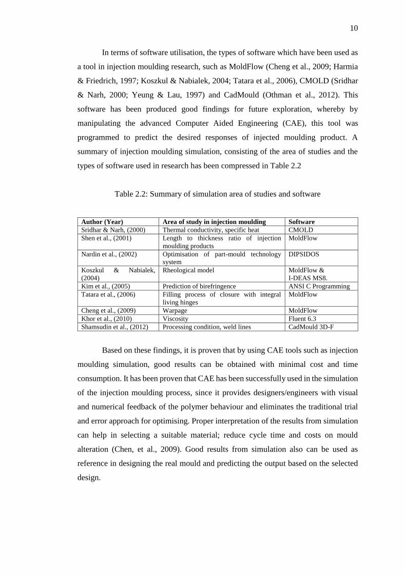
In terms of software utilisation, the types of software which have been used as
a tool in injection moulding research, such as MoldFlow (Cheng et al., 2009; Harmia
& Friedrich, 1997; Koszkul & Nabialek, 2004; Tatara et al., 2006), CMOLD (Sridhar
& Narh, 2000; Yeung & Lau, 1997) and CadMould (Othman et al., 2012). This
software has been produced good findings for future exploration, whereby by
manipulating the advanced Computer Aided Engineering (CAE), this tool was
programmed to predict the desired responses of injected moulding product. A
summary of injection moulding simulation, consisting of the area of studies and the
types of software used in research has been compressed in Table 2.2
Table 2.2: Summary of simulation area of studies and software
Author (Year) Area of study in injection moulding Software
Sridhar & Narh, (2000) Thermal conductivity, specific heat CMOLD
Shen et al., (2001) Length to thickness ratio of injection
moulding products
MoldFlow
Nardin et al., (2002) Optimisation of part-mould technology
system
DIPSIDOS
Koszkul & Nabialek,
(2004)
Rheological model MoldFlow &
I-DEAS MS8.
Kim et al., (2005) Prediction of birefringence ANSI C Programming
Tatara et al., (2006) Filling process of closure with integral
living hinges
MoldFlow
Cheng et al., (2009) Warpage MoldFlow
Khor et al., (2010) Viscosity Fluent 6.3
Shamsudin et al., (2012) Processing condition, weld lines CadMould 3D-F
Based on these findings, it is proven that by using CAE tools such as injection
moulding simulation, good results can be obtained with minimal cost and time
consumption. It has been proven that CAE has been successfully used in the simulation
of the injection moulding process, since it provides designers/engineers with visual
and numerical feedback of the polymer behaviour and eliminates the traditional trial
and error approach for optimising. Proper interpretation of the results from simulation
can help in selecting a suitable material; reduce cycle time and costs on mould
alteration (Chen, et al., 2009). Good results from simulation also can be used as
reference in designing the real mould and predicting the output based on the selected
design.

11
2.1.4 The effect of processing conditions
The injection moulding process is a cyclic process. This process consists of several
activities such as plastication; injection; packing; cooling, ejection and quality control
appliances. Having preliminary knowledge about these activities is vital hence the
present day competitive conditions that forced the manufacturing industries to produce
faster and cheaper product with a higher quality, such as minimum warpage, sink
marks, etc. Therefore, several important processing conditions for each stage of the
process may influence the quality of injection moulded plastic products. The
processing conditions such as melt temperature, mould temperature, injection pressure,
injection velocity, packing pressure and cooling time, need to be optimised in order to
achieve good results in injection moulding processes (Ozcelik & Erzurumlu, 2006)
To describe the influence of processing conditions towards injection moulding
products, for instance, based on Table 2.3 by increasing the injection pressure or
increasing mould temperature can produce shrinkage (Bryce, 1996). Meanwhile,
lowering back pressure, as well as lowering melt temperature can achieve less
degradation. These examples demonstrate that the basic moulding parameters do work
closely together and that changing a processing condition in one area may affect a
value of any property in another area. By understanding this relationship, it is possible
to minimize the number of adjustments required when it is necessary, making a
correction due to an unexpected change in some variable of the process (Bryce, 1996).
Table 2.3: Parameter change versus property effect (Bryce, 1996)
Parameter Properties Effect
Injection pressure increased Less shrinkage, higher gloss, less wrap, harder to eject
Injection pressure decreased More shrinkage, less gloss, more wrap, easier to eject
Back pressure increased Higher density, more degradation, fewer voids
Back pressure decreased Lower density, less degradation, more voids
Melt temperature increased Faster flow, more degradation, more brittle, flashing
Melt temperature decreased Slower flow, less degradation, less brittle, less flashing
Mould temperature increased Longer cycle, higher gloss, less wrap, less shrinkage
Mould temperature decreased Faster cycle, lower gloss, greater warp, higher

12
More often than not, depending on the cavities that being filled, high injection
speed is used for this material because fast filling speed will produce a uniform
temperature as it fills into the cavity. If the filling rate is slow, it may cause defects at
certain thin part due to rapid cooling when the first material enters the cavity.
Incomplete fill, lamination and warpage are the examples of defects due to slow speed
of injection, especially for polypropylene and its copolymers because it has a relatively
high crystalline melting temperature and solidify quickly in the cavity (Bauccio et al.,
1994).
The thickness of a component usually affects the processing conditions in
injection moulding. In this case, Table 2.4 proposed certain range of condition in the
injection moulding process, specifically for polypropylene artefacts, based on various
thicknesses.
Table 2.4: Certain ranges of condition for polypropylene artefacts (Bauccio et al.,
1994).
Moulding Conditions Thickness of sections
1.6 mm 3.2 mm 6.4 mm
Rear cylinder temperatures (0C) 193-216 193-204 193-204
Middle cylinder temperatures (0C) 204-232 193-216 193-216
Forward cylinder temperatures (0C) 216-249 204-232 204-216
Nozzle temperatures (0C) 193-216 193-216 193-216
Melt temperatures (0C) 204-249 204-232 193-216
Mould coolant temperatures (0C) 10-27 10-27 10-27
Hydraulic injection pressure (MPa) 4-10 4-10 4-10
Typical cycle time (s) 5-10 10-15 15-20
Plunger forward time (s) 15-25 25-35 35-60
Total cycle time (s) 15-25 25-35 35-60
Shrinkage (%) 1-2 1-2 1-2
The thickness varies from 1.6 mm to 6.4 mm. Based on the details in Table 2.4;
it shows that the melt temperature was reduced by the additional of thickness. With
regard of quality matters, variables such as injection speed, pressure, clamping

13
pressure, melt temperature, mould temperature and cycle time need to be monitored
(Bauccio et al., 1994).
Several previous studies have been used as references for the effects of the
injection moulding processing condition, as stated in Table 2.5. For example, to
support the statement saying that temperature and pressure are the major parameter
setting that influence the output of this process, previous researchers (Huang & Tai,
2001) have found that the order of the influence of process parameters on the warpage
of injected parts are first, packing pressure, followed by mould temperature; melt
temperature, packing time and cooling time. In addition, upon the findings, the effect
of interaction between mould temperature and melt temperature could not be ignored
(Huang & Tai, 2001)
Table 2.5: Previous study about the effects of processing condition
Author (Year) Response Processing conditions
( Huang & Tai, 2001) Warpage Packing pressure
(Fung et al., 2003) Yield stress and
elongation
Melt temperature
(Nagaoka et al.,2005) Core structure Injection speed
(Song et al., 2007) Part thickness Metering size, injection rate.
Other researchers (Fung et al., 2003), have concluded that the most influential
process factor and the most easily influenced mechanical properties can be rectified.
It was found that the melt temperature was the most influential factor to mechanical
properties of both yield stress and elongation. The yield stress was more influenced by
melting temperature than the elongation. The sequence of controllable factors that
affecting the yield stress was slightly different from the elongation, but the melt
temperature was still the most important factor above all (Fung et al., 2003)
A research conducted by a group of Japanese scientist (Nagaoka et al., 2005)
have studied about the effect of injection moulding parameters on the properties of
polypropylene sandwich. This research considers the moulding conditions such as
injection speed, cylinder temperature, and mould temperature were related to the
mechanical properties of the sandwich moulding. In the case of single material
sandwich moulding, injection speed seemed to play no significant role, even though it
was clearly demonstrated that the core volume increases with injection speed. Thus,

14
the dormant or active role of injection speed depending on the material system has
been highlighted (Nagaoka et al., 2005).
A study about thin wall injection moulding process can be a proper guideline
for manufacturing polypropylene hinges artefacts. A research (Song et al., 2007) had
examined the effects of injection process parameters on the moulding process for ultra-
thin wall plastic parts. As for the solutions, by using the orthogonal of Taguchi method
and numerical simulation, the influence of different process parameters such as
injection rate, injection pressure, melt temperature, metering size and part thickness,
in the moulding process for ultra-thin wall plastic parts were determined. Based on the
results, the part thickness was the decisive parameter to the moulding. On the other
hand, metering size and injection rate were the principal factors in the moulding
process. The accelerating injection rate can increase the filling ratio. Melt temperature
and injection pressure were the secondary factors, however, higher melt temperature
and injection pressure were also essential in the moulding process (Song et al., 2007).
Therefore; in summary, the part thickness, injection rate, melt temperature,
packing pressure, filling time and screw speed are some of the important factors that
need to be considered when performing an injection moulding process especially for
thin layer parts such as an integral hinge.
2.1.5 Optimisation method
The quality of the injection mouldings depends on the material characteristics,
the mould design and the process conditions. Taguchi Optimisation Method is one of
the popular methods used to determine the effect and the optimise process conditions
in order to optimise part quality such as shrinkage, warpage and strength. This method
is a statistical method, which developed by Dr. Genichi Taguchi to improve the quality
of manufactured goods. This method also can be applied in engineering,
biotechnology, marketing and advertising. Taguchi methods have been used widely in
engineering analysis to optimise the performance characteristics through the setting of
design parameters. Taguchi method is also a strong tool for the design of high quality
systems. To optimise designs for quality, performance, and cost, Taguchi
Optimisation Method presents a systematic approach that is simple and effective
(Taguchi et al., 2005).

15
Part design, mould design, machine performance and processing conditions are
some of the factors that will affect the quality of moulded parts. During production,
quality characteristics may deviate due to drifting or shifting of processing conditions
caused by machine wear, environmental change or operator fatigue. Determining
optimal process parameter settings critically influences productivity, quality, and cost
of production in the plastic injection moulding industry. Previously, production
engineers used either trial-and-error method or Taguchi’s parameter design method to
determine optimal process parameter settings for injection moulding. Yadav et al.
(2012) have made a review regarding the recent research in designing and determining
process parameters of injection moulding. A number of research works based on
various approaches have been performed in the domain of the parameter setting for
injection moulding. These approaches, including mathematical models, Taguchi
method, artificial neural networks (ANN), fuzzy logic, case based reasoning (CBR),
genetic algorithms (GA), finite element method (FEM), nonlinear modelling, response
surface methodology, linear regression analysis, Grey rational analysis and principal
component analysis (PCA) were described. The strength and the weakness of each
individual approaches have been discussed with the conclusions of the potential
research in determining process parameters for injection moulding.
Many published studies have emphasized the implementation of the Taguchi
Optimisation Method in improving the warpage in the injection moulded part (Gao &
Wang, 2008; Ozcelik & Sonat, 2009; Tang et al., 2007) as well as a sink index
(Erzurumlu & Ozcelik, 2006) and weld lines (Othman et al., 2012; Ozcelik, 2011; Xie
& Ziegmann, 2011).
To quote an example of Taguchi Optimisation Method, a research Oktem et
al.,(2007) has been conducted regarding how to reduce warpage problem which was
related to the shrinkage variation, depended on process parameters during production
of thin-shell plastic components for or automobile part. The results of this research
showed that warpage and shrinkage were improved by 2.17% and 0.7% respectively.
It can be clearly inferred from this conclusion that Taguchi Optimisation Method is
sufficient to solve the warpage problem with shrinkage for thin-shell plastic
components of or that part (Oktem et al., 2007)
Another example is mentioned in the paper published by researchers
(Erzurumlu & Ozcelik, 2006), consist of minimisation of the warpage and sink index
in terms of the process parameters of the plastic parts have different rib cross-section

16
types, and rib layout angle, via Taguchi Optimisation Method. This method was used
by exploiting mould analyses based on three level factorial designs. Orthogonal arrays
of Taguchi, the signal to noise ratio, the analysis of variance were utilized to find
optimal levels and the effect of process parameters on warpage and sink index
(Erzurumlu & Ozcelik, 2006)
There was a research about the influence of injection parameters and mould
materials on mechanical properties of acrylonitrile–butadiene–styrene (ABS) in plastic
injection moulding (Ozcelik et al., 2010). The study was about optimising the effect
of injection parameters such as melt temperature, packing pressure, cooling time and
injection pressure towards the mechanical properties of mouldings. Signal to noise
ratio for mechanical properties was calculated and the effect of the parameters on
mechanical properties was determined using the analysis of variance (ANOVA). The
regression analysis was also deployed to create linear mechanical models (Ozcelik et
al., 2010).
Another study about the application of back propagation (BP) neural-network
model to predict warpage and optimize the injected plastic parts has been developed
based on key process variables, including mould temperature, melt temperature,
packing pressure, packing time and cooling time during plastic injection moulding.
The approach uses a BP neural network trained by the input and output data obtained
from the finite element simulations which were performed on MoldFlow software
platform. The product selected for this study is an automobile glove compartment cap.
Trained by the results of finite element simulations conducted by orthogonal
experimental design method, the prediction system applies a mathematical equation
mapping the relationship between the process parameter values and the warpage value
of the plastic. It has been proved that the prediction system has the ability to predict
the warpage of the plastic within an error range of 2%. Process parameters have been
optimised with the help of the prediction system. Meanwhile, energy consumption and
production cycle were also taken into consideration. The optimised warpage value is
1.58 mm, which is shortened by 32.99% compared to the initial webpage result
2.358 mm. And the cooling time has been decreased from 20 s to 10 s, which will
greatly shorten the production cycle. The final product can satisfy with the matching
requirements and fit the automobile glove compartment well (Yin et al., 2010).
In order to obtain more accurate prediction of the service performance and
service life of polymers and the optimisation of processing parameters, a novel on-

17
line testing equipment had been developed (Wang et al., 2009). The results of this
project were compared with those obtained by the confining fluid technique. The
Pressure-Volume-Temperature (P-V-T) curves were consistent, which proved that the
new on-line measurement is feasible. The repeatability of the P-V-T measurement was
within 0.3%. Consequently, a new P-V-T database of typical commercial materials
could be established (Wang et al.,2009).
Some previous academics (Mehat & Kamaruddin, 2011) have studied the
mechanical properties of products made from recycled plastic by utilizing the Taguchi
Optimisation Method. By determining the optimal combination of factors and levels,
the appropriate blending ratio of virgin and recycled plastic can be evaluated from the
mechanical performance exhibited by the compound. The results reveal that the
product made of 25% recycled polypropylene and 75% virgin polypropylene exhibits
a better flexural modulus compared to the virgin form. The same product exhibits a
3.4% decrease in flexural strength.
Several scientists (Prashantha & Soulestin, 2009) have focused on the effect of
multi-walled carbon nanotube (MWNT) addition on shrinkage and warpage properties
of polypropylene injection mouldings before and after annealing. On the other hand, a
research (Kramschuster et al., 2005) had presented the effects of processing conditions
on the shrinkage and the warpage behaviour of a box-shaped, polypropylene part using
conventional and microcellular injection moulding. In this research, after the injection
moulding process reached steady state, the results show that the supercritical fluid
content and the injection speed affect the shrinkage and warpage of microcellular
injection moulded parts the most, whereas pack/hold pressure and pack/hold time have
the most significant effect of these defects (Kramschuster et al., 2005).
A research (Rajesh & Soulestin, 2012) had successfully defined the effect of
injection moulding parameters on nanofillers dispersion in masterbatch based
polypropylene-nanoclay nanocomposites. The effect of injection moulding parameters
(screw rotation speed, back pressure, injection flow rate and holding pressure) on the
nano filler dispersion of melt mixed polypropylene-nanoclay nanocomposites was
investigated. The nanocomposites containing 4 wt. % of clay were obtained by dilution
of a polypropylene-nanoclay masterbatch into a polypropylene matrix. The evaluation
of the dispersion degree was obtained from dynamic rheological measurements. The
storage modulus and complex viscosity exhibit significant dependence on the injection
moulding parameters. Polypropylene-nanoclay nanocomposite moulded using more

18
severe injection parameters (high shear and long residence time) displays the highest
storage modulus and complex viscosity, which illustrates the improved dispersion of
clay platelets. This better dispersion leads to better mechanical properties, particularly
higher Young modulus, tensile strength and unmatched impact strength. The major
individual parameter identified is the injection flow rate, whose increase improves
nanoclay dispersion. The combination of high back pressure and high screw rotational
speed is also necessary to optimize the dispersion of clay nano platelets (Rajesh &
Soulestin, 2012).
Since polymer materials exhibit extremely convoluted properties, the
complexity of the moulding process has become very tough to attain desired part
properties (Mehat et al., 2014). However, most research related to optimisation only
focus on a single response or quality characteristic. In reality, determining the
superlative process parameters and focusing on multi-responses are intricate tasks, but
are generally required (Khan et al., 2010). Therefore a constitutive approach to solve
multi-response problems using the combination of single responses through the
Taguchi Optimisation Method was needed to solve this problem.
Table 2.6 shows researchers related to multiple response optimisations.
Previous researchers (Annicchiarico et al., 2013; Antony & Anand, 2006; Fung &
Kang, 2005; Khan et al., 2010; Mehat & Kamaruddin, 2011; & Zhou & Turng, 2007)
have published several articles related to multiple responses optimisation.
To quote an example, a research (Mehat & Kamaruddin, 2011); had used the
accumulation of signal to noise ratio to define the optimum processing parameter in
their research. By combining the responses to be studied concurrently, the approach
seems to have improved the flexural modulus and strength of the produced part using
recycled plastic compared with the single response approach.
Therefore, the literatures have clearly shown that Taguchi Optimisation
Method has been used to determine optimum processing conditions for injection
moulding analysis and it was successfully proven. The author will use this method in
this research to achieve the objectives whereby optimise the processing condition and
to generate regression models for producing integral hinges made from polypropylene
nanoclay nanocomposites, via injection moulding process.

19
Table 2.6: Summary of multiple response optimisations.
Author (Year) Method of Optimisation Findings
Fung & Kang, 2005 Taguchi, Principal
Component Analysis
Optimum combination of process factor
and the most influential parameter for
friction properties,
Antony & Anand, 2006 Taguchi, Neuro Fuzzy
Model
Optimised responses for a double sided
surface mount technology of the electronic
assembly process.
Zhou & Turng, 2007 Gaussian process approach,
multi objective genetic
algorithm
Optimised system and process conditions
for minimizing injection pressure,
volumetric shrinkage/warpage and cycle
time.
Khan et al., 2010 Grey Relational Analysis
and Principle Component
Analysis
Optimal combination of parameter and
weighting value of tensile, compressive
and flexural strength.
Mehat & Kamaruddin,
2011
Taguchi Optimum processing condition for flexural
modulus and strength.
Annicchiarico et al.,
2013
Design of experiment Significant factors for shrinkage and part
mass.
2. 2 Polypropylene- nanoclay nanocomposites
Recently polypropylene nanocomposites have attracted much attention due to
advances in the methods of their manufacture. Great expectation has been directed to
this material and indeed it is not an exaggeration to suggest that an investigation into
polypropylene nanocomposites have occupied the major proportion of those studies
relating to polymer nanoclay nanocomposites (Mittal, 2009). Polymer nanocomposites
consisting of a polymer and layered silicate, whether it was modified or not, have
exhibited a remarkably improved mechanical and material properties when compared
to those pristine polymers. These improvements include a higher modulus, increased
in strength and better heat resistance. Recently polypropylene-nanoclay
nanocomposites have increased great attention due to their improvement in properties
such as high modulus, increased strength and heat resistance, decreased gas
permeability and flammability. Efforts have been established nowadays, whereby
many researchers have carried out more experiments concerning the combination of

20
polypropylene-nanoclay (Pavlidou & Papaspyrides, 2008; Sinha Ray & Okamoto,
2003).
By adding small amounts of nanoclay into polypropylene, both its melt
characteristic (processabilities) and solid characteristics (product properties) are
greatly altered. The main characteristic is that the non-Newtonian flow behaviour at
low shear rates becomes more notable and shows a yield flow feature. A second plateau
feature appears at low angular frequencies, which is more of a solid like characteristic.
Taken together, these melt characteristic will affect the flow processabilities of the
polymer (Mittal, 2009).
2.2.1 Micro mechanism, structure, morphology and properties.
In terms of the micro mechanism of plastic deformation during impact loading
of polypropylene-nanoclay nanocomposites, researchers (Yuan & Misra, 2006) have
examined and compared the condition with the unreinforced polypropylene under
identical conditions of processing to underscore the determining role of clay. The
addition of clay to polypropylene increases the impact strength in the temperature
range of 0 to +70 °C. The enhancement of toughness on reinforcement of
polypropylene-nanoclay is associated with change in the primary mechanism of plastic
deformation from crazing and vein-type in neat polypropylene to micro void-
coalescence-fibrillation process in the nanocomposite (Yuan & Misra, 2006).
As observed by Misra et al., (2010) the evolution of structure and phases during
pressure-induced crystallization of polymers had been summarised. The polymer
containing a dispersion of nanoparticles, in the pressure range of 0.1-200 MPa. The
model material for nanoparticles is nanoclay and the model polymer is polypropylene,
which can potentially form several crystalline phases. While the phase selection in
polypropylene is dictated by pressure and temperature, however, the introduction of
nanoparticles alters the nucleation and growth of phases via nanoparticles interface
driven evolution. To delineate and separate the effects of applied crystallization
pressure from nanoparticles effects, a relative comparison is made between neat
polypropylene and polypropylene containing a dispersion of nanoclay under similar
experimental conditions. The significant finding of the research was that nanoclay
interacts with the host polypropylene in a manner such that it alters the structural

21
morphology of [alpha] - and [gamma] -crystals of polypropylene. Furthermore,
nanoclay promotes the formation of [gamma] -phase at ambient pressure, suggesting
its role as structure and morphology director in the stabilization of the less accessible
[gamma] -phase, and with the possibility of epitaxial growth that enhances toughness.
The equilibrium melting point measurements point to thermodynamic interaction
between polypropylene-nanoclay, which is supported by the change in glass transition
temperature. Thus, the two components, nanoclay and pressure, together provide a
unique opportunity to tune hierarchical structures and phase evolution, which has
significant implication on physico-chemical and mechanical properties (Misra et al.
2010).
Significant differences in the microstructure occur when the polypropylene
matrix dispersed with 4wt. % and 8wt. % nanoclay. In neat polypropylene, crystals
nucleate in low to moderate crystallization pressure range of (∼0.1–60 MPa), while -
phase nucleates at a crystallization pressure of 60–200 MPa. In contrast to neat
polypropylene, the presence of nanoclay in the polymer matrix, promotes the
formation of phase at an ambient crystallization pressure of 0.1MPa. Nanoclay and
pressure-induced crystallization governs phase evolution and microstructure of
Polypropylene and is associated with change in the thermodynamic and physical
properties such as equilibrium melting point and glass transition temperature. This
change in equilibrium melting point and glass transition temperature has pointed the
thermodynamic interaction between polymer nanoparticles and nanoparticles interface
driven microstructural evolution. However, the effect of nanoparticles is less dramatic
when nanoclay content is increased from 4wt. % to 8wt. %, implying that the effect
maximizes at 4 wt. % nanoclay (Yuan et al. 2010).
A paper presents the results of a current study concerning the mechanical
properties of a polypropylene binder resin, enhanced by nanoclay filler. The study was
centred on the potential benefits obtained by the addition of especially surface treated
nanoclay on the stiffness, toughness and also on static and fatigue strength. Specimens
were produced by an injection moulding process with 3% by weight of nanoclay.
Surface treatment of the nanoclay promotes a tendency to increase stiffness and tensile
strength in comparison with composites filled by both commercial nanoclay and
unfilled material. Nanoclay filling significantly improves absorbed impact energy in
comparison with unfilled materials. Fatigue analysis shows that the materials tested in
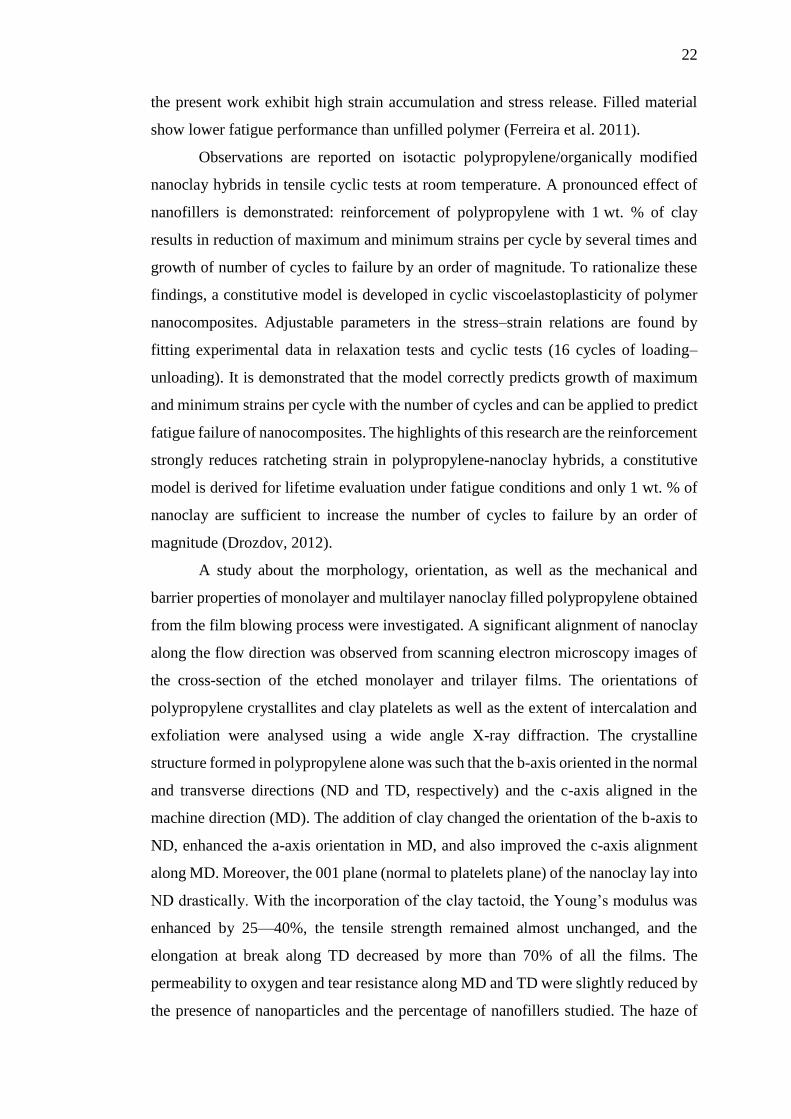
22
the present work exhibit high strain accumulation and stress release. Filled material
show lower fatigue performance than unfilled polymer (Ferreira et al. 2011).
Observations are reported on isotactic polypropylene/organically modified
nanoclay hybrids in tensile cyclic tests at room temperature. A pronounced effect of
nanofillers is demonstrated: reinforcement of polypropylene with 1 wt. % of clay
results in reduction of maximum and minimum strains per cycle by several times and
growth of number of cycles to failure by an order of magnitude. To rationalize these
findings, a constitutive model is developed in cyclic viscoelastoplasticity of polymer
nanocomposites. Adjustable parameters in the stress–strain relations are found by
fitting experimental data in relaxation tests and cyclic tests (16 cycles of loading–
unloading). It is demonstrated that the model correctly predicts growth of maximum
and minimum strains per cycle with the number of cycles and can be applied to predict
fatigue failure of nanocomposites. The highlights of this research are the reinforcement
strongly reduces ratcheting strain in polypropylene-nanoclay hybrids, a constitutive
model is derived for lifetime evaluation under fatigue conditions and only 1 wt. % of
nanoclay are sufficient to increase the number of cycles to failure by an order of
magnitude (Drozdov, 2012).
A study about the morphology, orientation, as well as the mechanical and
barrier properties of monolayer and multilayer nanoclay filled polypropylene obtained
from the film blowing process were investigated. A significant alignment of nanoclay
along the flow direction was observed from scanning electron microscopy images of
the cross-section of the etched monolayer and trilayer films. The orientations of
polypropylene crystallites and clay platelets as well as the extent of intercalation and
exfoliation were analysed using a wide angle X-ray diffraction. The crystalline
structure formed in polypropylene alone was such that the b-axis oriented in the normal
and transverse directions (ND and TD, respectively) and the c-axis aligned in the
machine direction (MD). The addition of clay changed the orientation of the b-axis to
ND, enhanced the a-axis orientation in MD, and also improved the c-axis alignment
along MD. Moreover, the 001 plane (normal to platelets plane) of the nanoclay lay into
ND drastically. With the incorporation of the clay tactoid, the Young’s modulus was
enhanced by 25—40%, the tensile strength remained almost unchanged, and the
elongation at break along TD decreased by more than 70% of all the films. The
permeability to oxygen and tear resistance along MD and TD were slightly reduced by
the presence of nanoparticles and the percentage of nanofillers studied. The haze of

23
the nanocomposite films increased upon the presence of clay particles, except in the
case of low clay contents of 1.5 and 2.5 wt.% (Tabatabaei & Ajji, 2011).
2.2.2 Preparation methods
The preparations of polypropylene-nanoclay nanocomposites are divided into three
main methods according to the starting materials and processing techniques. The
methods are the intercalation of polymer or pre-polymer from solution, in situ
intercalative polymerization method and melt intercalation method (Pavlidou &
Papaspyrides, 2008)
The intercalation of polymer or pre-polymer from solution is the first method
found in preparing the polypropylene-nanoclay. This method is based on a solvent
system in which the polymer or pre-polymer is soluble and the silicate layers are
swellable. The layered silicate is first swollen in a solvent, such as water, chloroform,
or toluene. When the polypropylene-nanoclay solutions are mixed, the polymer chains
intercalate and displace the solvent within the interlayer of the silicate. Upon solvent
removal, the intercalated structure remains, resulting in polypropylene-nanoclay
nanocomposite (Pavlidou & Papaspyrides, 2008)
The in situ intercalative polymerization method is the second method of
preparing the polypropylene-nanoclay. This method was successfully applied by
manipulating the ability of soluble metallocene catalysts to intercalate inside silicate
layers, and to promote the coordination polymerization of propylene. A synthetic
hectorite was first treated with methylaluminoxane in order to remove the acidic
protons, and to prepare the interlayer spacing for receiving the transition metal catalyst.
Another method was also discovered by making the layered silicate swollen within the
liquid monomer so the polymer formation can occur between the intercalated sheets
(Pavlidou & Papaspyrides, 2008)
The third method of polypropylene-nanoclay preparation is through melt
intercalation. Recently, this technique has become the standard for the preparation of
polypropylene-nanoclay nanocomposites (Sinha Ray & Okamoto, 2003). During
polymer intercalation from solution, a relatively large number of solvent molecules
have to be desorbed from the host to accommodate the incoming polymer chains. The
desorbed solvent molecules gain one translational degree of freedom, and the resulting

24
entropic gain compensates for the decrease in conformational entropy of the confined
polymer chains. This method involves annealing, statically or under shear, and a
mixture of the polypropylene-nanoclay above the softening point of the polymer.
While annealing, the polymer chains diffuse from the bulk polymer melt into the
galleries between the silicate layers. A range of nanocomposites with structures from
intercalated to exfoliate can be obtained, depending on the degree of penetration of the
polymer chains into the silicate galleries. So far, experimental results indicate that the
outcome of polymer intercalation depends critically on silicate function and
constituent interactions. This method has great advantages over either in situ
intercalative polymerization or polymer solution intercalation such as this method is
environmentally nonthreatening due to the nonexistence of organic solvents. It is also
compatible with current industrial process, such as extrusion and injection moulding.
The direct melt intercalation was highly specific for this polymer, leading to new
hybrids that were previously inaccessible. Last but not lease, the advantage of this
method is the absence of a solvent, which made direct melt intercalation as an
economic process for industries from a waste perspective (Sinha Ray & Okamoto,
2003).
A study (Albdiry & Yousif, 2013) had been conducted to determine the
difference of polymer-nanoclay processing techniques. The researchers have
performed the review in order to study the relationship between the techniques and the
final characteristics and properties of polymer-nanoclay nanocomposites, in terms of
the final structure formation, rheological perfection, thermo-mechanical and thermal
properties. Thermodynamic and physical properties such as glass transition
temperature, equilibrium melting point and crystallization temperature were also
discussed in this review. The review concluded that the altering process technique
(type and/or parameters) highly influences the final nanostructure morphology as well
as the thermodynamic and mechanical properties of nanoclay/polymer composites
(Albdiry & Yousif, 2013).
Therefore, based on these findings, melt intercalation via twin screw
compounder was chosen as the preparation method for polypropylene-nanoclay in this
research.

110
REFERENCES
Albdiry, M., & Yousif, B. (2013). A critical review on the manufacturing processes in
relation to the properties of nanoclay/polymer composites. Journal of Composite
Materials, 47(9), 1093-1115
Alcock, B., Cabrera, N. O., Barkoula, N. M., Reynolds, C. T., Govaert, L. E., & Peijs,
T. (2007). The effect of temperature and strain rate on the mechanical properties
of highly oriented polypropylene tapes and all-polypropylene composites.
Composites Science and Technology, 67(10), 2061–2070.
Altan, M. (2010). Reducing shrinkage in injection moldings via the Taguchi, ANOVA
and neural network methods. Materials & Design, 31(1), 599–604.
Annicchiarico, D., Attia, U. M., & Alcock, J. R. (2013). Part mass and shrinkage in
micro injection moulding: Statistical based optimisation using multiple quality
criteria. Polymer Testing, 32(6), 1079–1087.
Antony, J., & Anand, R. (2006). Multiple response optimization using Taguchi
methodology and neuro-fuzzy based model. Journal of Manufacturing
Technology Management, 17(7), 908-925.
Ataeefard, M., & Moradian, S. (2010). Surface properties of
polypropylene/organoclay nanocomposites. Applied Surface Science, 257(6),
2320–2326.
Aydın, S., Yazıcı, H., Baradan, B., AydIn, S., & YazIcI, H. (2008). High temperature
resistance of normal strength and autoclaved high strength mortars incorporated
polypropylene and steel fibers. Construction and Building Materials, 22(4), 504–
512.
Azaman, M. D., Sapuan, S. M., Sulaiman, S., Zainudin, E. S., & Khalina, A. (2013).
Shrinkages and warpage in the processability of wood-filled polypropylene
composite thin-walled parts formed by injection molding. Materials & Design,
52, 1018–1026.
Bauccio, M., Flint, V., Collins, S., Frueh, S., & Boring, R. (1994). ASM engineering
materials reference book. CRC.

111
Beaumont, J., Nagel, R., & Sherman, R. (2002). Successful injection molding.
Cincinnati: Hanser Publishers.
Behnood, A., & Ghandehari, M. (2009). Comparison of compressive and splitting
tensile strength of high-strength concrete with and without polypropylene fibers
heated to high temperatures. Fire Safety Journal, 44(8), 1015–1022.
Bhattacharya, S., Kamal, M., & Gupta, R. (2008). Polymeric nanocomposites: theory
and practice. Munich:Carl Hanser Publishers.
Bozdana, A. T., & Eyercioglu, Ö. (2002). Development of an expert system for the
determination of injection moulding parameters of thermoplastic materials: EX-
PIMM. Journal of Materials Processing Technology, 128(1-3), 113–122.
Brannon, P. J. (1992). A Study of Failure Prediction in Polypropylene Living Hinges.
University of Massachusetts Lowell.Ph.D. Thesis.
Bryce, D. (1996). Plastic injection molding. Society of Manufacturing Engineers.
BYK Additives &Instruments. (2013). Technical Information B-RI 10 Cloisite
Nanocomposite Additive for Halogan free Flame Retardants.
Chen, C.-P., Chuang, M.-T., Hsiao, Y.-H., Yang, Y.-K., & Tsai, C.-H. (2009).
Simulation and experimental study in determining injection molding process
parameters for thin-shell plastic parts via design of experiments analysis. Expert
Systems with Applications, 36(7), 10752–10759.
Cheng, X. M., Zhou, L., & Sheng, N. Y. (2009). Injection Molding and Warpage of
Thin-walled Parts Based on Simulated Deformation. In IEEE International
Conference on Computational Intelligence and Software Engineering, 2009.
CiSE 2009 (pp. 1–4).
Chinellato, A. C., Vidotti, S. E., Hu, G. H., & Pessan, L. A. (2010). Compatibilizing
effect of acrylic acid modified polypropylene on the morphology and
permeability properties of polypropylene/organoclay nanocomposites.
Composites Science and Technology, 70(3), 458–465.
Demirer, A., Soydan, Y., & Kapti, A. O. (2007). An experimental investigation of the
effects of hot runner system on injection moulding process in comparison with
conventional runner system. Materials & Design, 28(5), 1467–1476.
Devore, J., & Farnum, N. (1999). Applied Statistics for Engineers and Scientist. Pacific
Groove, CA: Brooks/Cole.
Dong, Y., & Bhattacharyya, D. (2008). Effects of clay type, clay/compatibiliser
content and matrix viscosity on the mechanical properties of
polypropylene/organoclay nanocomposites. Composites Part A: Applied Science
and Manufacturing, 39(7), 1177–1191.

112
Dong, Y., Bhattacharyya, D., & Hunter, P. J. (2008). Experimental characterisation
and object-oriented finite element modelling of polypropylene/organoclay
nanocomposites. Composites Science and Technology, 68(14), 2864–2875.
Drozdov, a. D., Høg Lejre, a.-L., & Christiansen, J. deC. (2009). Viscoelasticity,
viscoplasticity, and creep failure of polypropylene/clay nanocomposites.
Composites Science and Technology, 69(15-16), 2596–2603.
Drozdov, A. (2012). Cyclic viscoelastoplasticity of polypropylene/nanoclay
composites. Mechanics of Time-Dependent Materials, 16(4), 397-425.
Drozdov, A. D., Jensen, E. A., & Christiansen, J. de C. (2010). Nonlinear time-
dependent response of polypropylene/nanoclay melts: Experiments and modeling.
Computational Materials Science, 47(3), 807–816.
Dumitrescu, O. R., Baker, D. C., Foster, G. M., & Evans, K. E. (2005). Near infrared
spectroscopy for in-line monitoring during injection moulding. Polymer Testing,
24(3), 367–375.
Erzurumlu, T., & Ozcelik, B. (2006). Minimization of warpage and sink index in
injection-molded thermoplastic parts using Taguchi optimization method.
Materials & Design.
Ferreira, J. A. M., Reis, P. N. B., Costa, J. D. M., Richardson, B. C. H., & Richardson,
M. O. W. (2011). A study of the mechanical properties on polypropylene
enhanced by surface treated nanoclays. Composites Part B: Engineering, 42(6),
1366–1372.
Fung, C., & Kang, P. (2005). Multi-response optimization in friction properties of PBT
composites using Taguchi method and principle component analysis, 170, 602–
610.
Fung, C.-P., Huang, C.-H., & Doong, J.-L. (2003). The Study on the Optimization of
Injection Molding Process Parameters with Gray Relational Analysis. Journal of
Reinforced Plastics and Composites, 22(1), 51–66.
Galgali, G., Agarwal, S., & Lele, A. (2004). Effect of clay orientation on the tensile
modulus of polypropylene-nanoclay composites. Polymer, 45(17), 6059–6069.
Gao, Y., & Wang, X. (2008). An effective warpage optimization method in injection
molding based on the Kriging model. The International Journal of Advanced
Manufacturing Technology, 37(9-10), 953-960
Gordon Jr, M. (2010). Total quality process control for injection molding. (Vol. 5).
New Jersey: John Wiley & Sons.
Groover, M. (2007). Fundamentals of modern manufacturing: materials processes, and
systems. John Wiley & Sons.

113
Harmia, T., & Friedrich, K. (1997). Local fracture resistance based on microstructural
efficiency concept and simulation of injection molding. Theoretical and Applied
Fracture Mechanics, 26(1), 47–52.
Hassan, H., Regnier, N., & Defaye, G. (2009). A 3D study on the effect of gate location
on the cooling of polymer by injection molding. International Journal of Heat
and Fluid Flow, 30(6), 1218–1229.
Hassan, H., Regnier, N., Le Bot, C., & Defaye, G. (2010). 3D study of cooling system
effect on the heat transfer during polymer injection molding. International
Journal of Thermal Sciences, 49(1), 161–169.
Hassan, H., Regnier, N., Pujos, C., Arquis, E., & Defaye, G. (2010). Modeling the
effect of cooling system on the shrinkage and temperature of the polymer by
injection molding. Applied Thermal Engineering, 30(13), 1547–1557.
Hill, D. (1996). Further studies of the injection moulding process. Applied
Mathematical Modelling, 20(10), 719–730.
Home, M., Kubo, S., & Kamiya, D. (2001). Molding 3-DOF Planar Positioning and
Orientation Tables with Large-Deflective Polymer Hinges ancl Links for
Packaging Manufacturing Systems. In International Symposium on Electronic
Materials and Packaging (Vol. 00, pp. 196–201).
Horie, M., Okabe, Y., Yamamoto, M., & Kamiya, D. (2005). Study on Long Life
Large-Deflective Hinges in Molded Pantograph Mechanisms based on Cyclic
Load-Bending Fatigue Test. In 2005 International Symposium on Electronics
Materials and Packaging (Vol. 2, pp. 137–142). Ieee.
Hsieh, K.-L., Tong, L.-I., Chiu, H.-P., & Yeh, H.-Y. (2005). Optimization of a multi-
response problem in Taguchi’s dynamic system. Computers & Industrial
Engineering, 49(4), 556–571.
Huang, M. S., & Lin, T. Y. (2008). An innovative regression model-based searching
method for setting the robust injection molding parameters. Journal of Materials
Processing Technology, 198(1), 436–444.
Huang, M.-C., & Tai, C.-C. (2001). The effective factors in the warpage problem of
an injection-molded part with a thin shell feature. Journal of Materials
Processing Technology, 110(1), 1–9.
Ineos. (2007). Polypropylene Processing Guide.
ISO527-2. (1993). Plastics – Determination of Tensile Properties – Part 2 Test
Conditions for Moulding and Extrusion Plastics.
Khan, Z. A., Kamaruddin, S., & Noor, A. (2010). Feasibility study of use of recycled
High Density Polyethylene and multi response optimization of injection
moulding parameters using combined grey relational and principal component
analyses. Materials and Design, 31(6), 2925–2931.

114
Khor, C. Y., Ariff, Z. M., Ani, F. C., Mujeebu, M. A., Abdullah, M. Z. K., & Joseph,
M. A. (2010). Three-dimensional numerical and experimental investigations on
polymer rheology in meso-scale injection molding. International
Communications in Heat and Mass Transfer, 37(2), 131–139.
Kim, H. ., Son, J. ., & Im, Y. . (2003). Gate location design in injection molding of an
automobile junction box with integral hinges. Journal of Materials Processing
Technology, 140(1-3), 110–115.
Kim, K. H., Isayev, A. I., Kwon, K., & van Sweden, C. (2005). Modeling and
experimental study of birefringence in injection molding of semicrystalline
polymers. Polymer, 46(12), 4183–4203.
Koszkul, J., & Nabialek, J. (2004). Viscosity models in simulation of the filling stage
of the injection molding process. Journal of Materials Processing Technology,
157-158, 183–187.
Kramschuster, A., Cavitt, R., Ermer, D., Chen, Z., & Turng, L.-S. (2005). Quantitative
study of shrinkage and warpage behavior for microcellular and conventional
injection molding. Polymer Engineering & Science, 45(10), 1408–1418.
Kumar, A., Ghoshdastidar, P. S., & Muju, M. K. (2002). Computer simulation of
transport processes during injection mold- ® lling and optimization of the
molding conditions. Journal of Materials Processing Technology, 120(1-3), 438–
449.
Kumar, A. P., Depan, D., Singh Tomer, N., & Singh, R. P. (2009). Nanoscale particles
for polymer degradation and stabilization—Trends and future perspectives.
Progress in Polymer Science, 34(6), 479–515.
Kuram, E., Tasci, E., Altan, A. I., Medar, M. M., Yilmaz, F., & Ozcelik, B. (2013).
Investigating the effects of recycling number and injection parameters on the
mechanical properties of glass-fibre reinforced nylon 6 using Taguchi method.
Materials & Design, 49, 139–150.
Ladhari, A., Ben Daly, H., Belhadjsalah, H., Cole, K. C., & Denault, J. (2010).
Investigation of water absorption in clay-reinforced polypropylene
nanocomposites. Polymer Degradation and Stability, 95(4), 429–439.
Lei, S. G., Hoa, S. V, & Ton-That, M. T. (2006). Effect of clay types on the processing
and properties of polypropylene nanocomposites. Composites Science and
Technology, 66(10), 1274–1279.
Lertwimolnun, W., & Vergnes, B. (2005). Influence of compatibilizer and processing
conditions on the dispersion of nanoclay in a polypropylene matrix. Polymer,
46(10), 3462–3471.
Liao, S. J., Chang, D. Y., Chen, H. J., Tsou, L. S., Ho, J. R., Yau, H. T., … Su, Y. C.
(2004). Optimal process conditions of shrinkage and warpage of thin-wall parts.
Polymer Engineering and Science, 44(5), 917–928.

115
Lotte Chemical Titan (M) Sdn Bhd. (2014). Titan Pro 6331 Product Data.
Massé, H., Arquis, É., Delaunay, D., Quilliet, S., & Le Bot, P. H. (2004). Heat transfer
with mechanically driven thermal contact resistance at the polymer–mold
interface in injection molding of polymers. International Journal of Heat and
Mass Transfer, 47(8-9), 2015–2027.
Mehat, N., & Kamaruddin, S. (2011). Multi-response optimization of injection
moulding processing parameters using the Taguchi method. Polymer-Plastics
Technology and Engineering, 50(15), 1519-1526.
Mehat, N., Kamaruddin, S., & Othman, A. (2012). Reducing the Shrinkage in Plastic
Injection Moulded Gear via Grey-Based-Taguchi Optimization Method. In
Proceedings of the World Congress on Engineering 2012 Vol III (pp. 1–4).
Mehat, N., Kamaruddin, S., & Othman, A. (2014). Hybrid Integration of Taguchi
Parametric Design, Grey Relational Analysis, and Principal Component Analysis
Optimization for Plastic Gear Production. Chinese Journal of Engineering, 2014.
Mehat, N. M. N. M., & Kamaruddin, S. (2011). Optimization of mechanical properties
of recycled plastic products via optimal processing parameters using the Taguchi
method. Journal of Materials Processing Technology, 211(12), 1989-1994.
Mehat, N. N. M., & Kamaruddin, S. (2011). Multi-Response Optimization of Injection
Moulding Processing Parameters Using the Taguchi Method. Polymer-Plastics
Technology and Engineering, 50(15), 1519–1526.
Mekhilef, N., Ait-Kadi, A., & AjjD, A. (1995). Weld lines in injetion moulded
immiscible blends: Model prediction and experimental results. Polymer, 36(10),
2033–2042.
Menges, G., Mohren, P., & Michaeli, W. (2001). How to make injection molds. Carl
Hanser Verlag GmbH & Co. KG.
Misra, R. D. K., Yuan, Q., Chen, J., & Yang, Y. (2010). Hierarchical structures and
phase nucleation and growth during pressure-induced crystallization of
polypropylene containing a dispersion of nanoclay: The impact on physical and
mechanical properties. Materials Science and Engineering: A, 527(9), 2163–
2181.
Mittal, V. (2009). Optimization of polymer nanocomposite properties. John Wiley &
Sons.
Modesti, M., Lorenzetti, A., Bon, D., & Besco, S. (2006). Thermal behaviour of
compatibilised polypropylene nanocomposite: Effect of processing conditions.
Polymer Degradation and Stability, 91(4), 672–680.
Montgomery, D. C. (2009). Design and Analysis of Experiments (7th Editio). Danvers,
MA: John Wiley & Sons.

116
Na, B., Wang, K., Zhang, Q., Du, R., & Fu, Q. (2005). Tensile properties in the
oriented blends of high-density polyethylene and isotactic polypropylene
obtained by dynamic packing injection molding. Polymer, 46(9), 3190–3198.
Nagaoka, T., Ishiaku, U. S., Tomari, T., Hamada, H., & Takashima, S. (2005). Effect
of molding parameters on the properties of PP/PP sandwich injection moldings.
Polymer Testing, 24(8), 1062–1070.
Nardin, B., Kuzman, K., & Kampus, Z. (2002). Injection moulding simulation results
as an input to the injection moulding process. Journal of Materials Processing
Technology, 130-131, 310–314.
Oktem, H., Erzurumlu, T., & Uzman, I. (2007). Application of Taguchi optimization
technique in determining plastic injection molding process parameters for a thin-
shell part. Materials & Design, 28(4), 1271–1278.
Osswald, T., Turng, L., & Gramann, P. (2008). Injection molding handbook. Hanser
Verlag.
Othman, M. H., Hasan, S., Ibrahim, M. Z., & Li, L. (2013). The Effects of Mould
Design on Shrinkage and Warpage of Polypropylene Integral Hinges. In 3rd
International Conference on Trends in Mechanical and Industrial Engineering
(ICTMIE’2013) January (pp. 270–272). Kuala Lumpur, Malaysia: prscentre.org.
Othman, M. H., Shamsudin, S., & Hasan, S. (2012). The Effects of Injection Moulding
Processing Parameters and Mould Gate Size towards Weld Line Strength.
Advanced Mechanics and Materials, 229-231, 2536–2540.
Ozcelik, B. (2011). Optimization of injection parameters for mechanical properties of
specimens with weld line of polypropylene using Taguchi method. International
Communications in Heat and Mass Transfer, 38(8), 1067-1072.
Ozcelik, B., & Erzurumlu, T. (2006). Comparison of the warpage optimization in the
plastic injection molding using ANOVA, neural network model and genetic
algorithm. Journal of Materials Processing Technology, 171(3), 437–445.
Ozcelik, B., Ozbay, A., & Demirbas, E. (2010). Influence of injection parameters and
mold materials on mechanical properties of ABS in plastic injection molding.
International Communications in Heat and Mass Transfer, 37(9), 1359–1365.
Ozcelik, B., & Sonat, I. (2009). Warpage and structural analysis of thin shell plastic in
the plastic injection molding. Materials & Design, 30(2), 367–375.
Paci, M., Filippi, S., & Magagnini, P. (2010). Nanostructure development in nylon 6-
Cloisite® 30B composites. Effects of the preparation conditions. European
Polymer Journal, 46(5), 838–853.
Pantani, R., Coccorullo, I., Speranza, V., & Titomanlio, G. (2005). Modeling of
morphology evolution in the injection molding process of thermoplastic polymers.
Progress in Polymer Science, 30(12), 1185–1222.

117
Pantani, R., Coccorullo, I., Speranza, V., & Titomanlio, G. (2007). Morphology
evolution during injection molding: Effect of packing pressure. Polymer, 48(9),
2778–2790.
Pavlidou, S., & Papaspyrides, C. D. (2008). A review on polymer–layered silicate
nanocomposites. Progress in Polymer Science, 33(12), 1119–1198.
Pettarin, V., Brun, F., Viana, J. C., Pouzada, A. S., & Frontini, P. M. (2013).
Toughness distribution in complex PP/nanoclay injected mouldings. Composites
Science and Technology, 74, 28–36.
Prashantha, K., & Soulestin, J. (2009). Taguchi analysis of shrinkage and warpage of
injection-moulded polypropylene/multiwall carbon nanotubes nanocomposites.
Express Polym Lett, 3(10), 630-638
Rajesh, J., & Soulestin, J. (2012). Effect of injection molding parameters on nanofillers
dispersion in masterbatch based PP-clay nanocomposites. EXPRESS polymer
Letters, 6(3), 237-248.
Roy, R. (2001). Design of experiments using the Taguchi approach: 16 steps to
product and process improvement. John Wiley & Sons.
Santos, K. S., Liberman, S. A., Oviedo, M. A. S., & Mauler, R. S. (2009). Optimization
of the mechanical properties of polypropylene-based nanocomposite via the
addition of a combination of organoclays. Composites Part A: Applied Science
and Manufacturing, 40(8), 1199–1209.
Shen, Y. K., Yeh, P. H., & Wu, J. S. (2001). Numerical simulation for thin wall
injection molding of fiber-reinforced thermoplastics. International
Communications in Heat and Mass Transfer, 28(8), 1035–1042.
Shen, Y.-K., Wu, C.-W., Yu, Y.-F., & Chung, H.-W. (2008). Analysis for optimal gate
design of thin-walled injection molding. International Communications in Heat
and Mass Transfer, 35(6), 728–734.
Sinha Ray, S., & Okamoto, M. (2003a). Polymer/layered silicate nanocomposites: a
review from preparation to processing. Progress in Polymer Science, 28(11),
1539–1641.
Sinha Ray, S., & Okamoto, M. (2003b). Polymer/layered silicate nanocomposites: a
review from preparation to processing. Progress in Polymer Science, 28(11),
1539–1641.
Song, M. C., Liu, Z., Wang, M. J., Yu, T. M., & Zhao, D. Y. (2007). Research on
effects of injection process parameters on the molding process for ultra-thin wall
plastic parts. Journal of Materials Processing Technology, 187-188, 668–671.
Spina, R. (2004). Injection moulding of automotive components: comparison between
hot runner systems for a case study. Journal of Materials Processing Technology,
155-156, 1497–1504.

118
Sridhar, L., & Narh, K. A. (2000). The effect of temperature dependent thermal
properties on process parameter prediction in injection molding. International
Communications in Heat and Mass Transfer, 27(3), 325–332.
Tabatabaei, S., & Ajji, A. (2011). Structure-orientation-properties relationships for
polypropylene nanoclay composite films. Journal of Plastic Film and Sheeting,
27(1-2), 87-115.
Taguchi, G., Chowdhury, S., & Wu, Y. (2005). Taguchi’s quality engineering
handbook. Hoboken, NJ: John Wiley & Sons.
Tang, S. H., Tan, Y. J., Sapuan, S. M., Sulaiman, S., Ismail, N., & Samin, R. (2007).
The use of Taguchi method in the design of plastic injection mould for reducing
warpage. Journal of Materials Processing Technology, 182(1-3), 418–426.
Tanyildizi, H. (2009). Statistical analysis for mechanical properties of polypropylene
fiber reinforced lightweight concrete containing silica fume exposed to high
temperature. Materials & Design, 30(8), 3252–3258.
Tatara, R. a. A., Sievers, R. M. M., & Hierzer, V. (2006). Modeling the injection
molding processing of a polypropylene closure having an integral hinge. Journal
of Materials Processing Technology, 176(1-3), 200–204.
Uddeholm. (2014). AISI D2 Cold work tool steel.
Valera-Zaragoza, M., Ramírez-Vargas, E., Medellín-Rodríguez, F. J., & Huerta-
Martínez, B. M. (2006). Thermal stability and flammability properties of
heterophasic PP–EP/EVA/organoclay nanocomposites. Polymer Degradation
and Stability, 91(6), 1319–1325.
Wang, J. (2012). Injection Molding Process | Some Critical Issues | InTechOpen. In
Tech.
Wang, J., Xie, P., Ding, Y., & Yang, W. (2009). On-line testing equipment of P-V-T
properties of polymers based on an injection molding machine. Polymer Testing,
28(3), 228–234.
Xie, L., & Ziegmann, G. (2011). Mechanical properties of the weld line defect in micro
injection molding for various nano filled polypropylene composites. Journal of
Alloys and Compounds, 509(2), 226–233.
Yadav, R. A., Scholar, R., Joshi, P. S. V, & Kamble, A. P. N. K. (2012). Recent
Methods for Optimization of Plastic Injection Molding Process - A Literature
Review. International Journal of Scientific & Engineering Research, 3(12), 1–8.
Yeung, V. W. S., & Lau, K. H. (1997). Injection moulding, [`]C-MOLD’ CAE package,
process parameter design and quality function deployment: A case study of
intelligent materials processing. Journal of Materials Processing Technology,
63(1-3), 481–487.

119
Yin, F., Mao, H., Hua, L., Guo, W., & Shu, M. (2011). Back Propagation neural
network modeling for warpage prediction and optimization of plastic products
during injection molding. Materials & Design, 32(4), 1844–1850.
Yuan, Q., Chen, J., Yang, Y., & Misra, R. D. K. (2010). Nanoparticle interface driven
microstructural evolution and crystalline phases of polypropylene: The effect of
nanoclay content on structure and physical properties. Materials Science and
Engineering: A, 527(21-22), 6002–6011.
Yuan, Q., & Misra, R. D. K. (2006). Impact fracture behavior of clay-reinforced
polypropylene nanocomposites. Polymer, 47(12), 4421–4433.
Yuan, Q., Rajan, V. G., & Misra, R. D. K. (2008). Nanoparticle effects during
pressure-induced crystallization of polypropylene. Materials Science and
Engineering: B, 153(1-3), 88–95.
Zahedi, M., Pirayesh, H., Khanjanzadeh, H., & Tabar, M. M. (2013). Organo-modified
montmorillonite reinforced walnut shell/polypropylene composites. Materials &
Design, 51, 803–809.
Zhou, J., & Turng, L. (2007). Adaptive multiobjective optimization of process
conditions for injection molding using a Gaussian process approach. Advances in
Polymer Technology.