The “Michell” Crankless Engine – Why was it not a ... · PDF fileThe Piston...
25
The Piston Engine Revolution 248 The “Michell” Crankless Engine – Why was it not a commercial success? John A. Anning At the beginning of the twentieth century, when the internal combustion engine was being developed for automobiles and aircraft, some designers arranged for the cylinders to be parallel to the output shaft. These became known as axial or barrel engines. They utilised either the swash plate or wobbleplate principles. The most promising was the Michell Crankless Engine, which was patented in 1917. AGM Michell FRS (1870-1959) was an Australian engineer best known for the design of the “Michell” tilting pad thrust bearing, patented in the UK and Australia in 1905. By the end of WWI Michell was a wealthy man from royalties and applied the tilting pad principle to an axial engine. The principle was first applied to compressors and by 1920 the first IC engine was made. An advantage is that perfect primary and secondary balance can be achieved at all rotational speeds. Michell formed Crankless Engines (Australia) Pty Ltd. A number of engines were built and installed in existing production vehicles. He realised that for the future commercialisation an overseas involvement was essential so offices were opened in London and New York. The Michell crankless principle still remains the most efficient method of converting linear into rotary motion. By the late 1920s with the world depression the Australian company was forced into receivership. A business analysis is given as to the possible reasons for its failure to achieve commercial success. It deserves its place in the panoply of IC engine history. KEYWORDS: Axial, Crankless, Slant, Swash Plate, Wobble plate, Tilting Pad Introduction When the internal combustion engine was being developed and continually improved at a great pace for both automotive and aircraft applications from the early years of the twentieth century, an increase in power, reduction in weight, improvement in reliability and minimum frontal area became important criteria. This gave rise to a fertile field of new designs, innovations and patent applications, and still continues to this day. Many of these relate to the elimination of the well established and proven piston, connecting rod and crankshaft kinematic train, the dynamics of which were well understood from steam engine practice. Many of the
Transcript of The “Michell” Crankless Engine – Why was it not a ... · PDF fileThe Piston...
The Piston Engine Revolution
248
The “Michell” Crankless Engine – Why was it not a commercial success? John A. Anning At the beginning of the twentieth century, when the internal combustion engine was being developed for automobiles and aircraft, some designers arranged for the cylinders to be parallel to the output shaft. These became known as axial or barrel engines. They utilised either the swash plate or wobbleplate principles. The most promising was the Michell Crankless Engine, which was patented in 1917. AGM Michell FRS (1870-1959) was an Australian engineer best known for the design of the “Michell” tilting pad thrust bearing, patented in the UK and Australia in 1905. By the end of WWI Michell was a wealthy man from royalties and applied the tilting pad principle to an axial engine.
The principle was first applied to compressors and by 1920 the first IC engine was made. An advantage is that perfect primary and secondary balance can be achieved at all rotational speeds. Michell formed Crankless Engines (Australia) Pty Ltd. A number of engines were built and installed in existing production vehicles. He realised that for the future commercialisation an overseas involvement was essential so offices were opened in London and New York.
The Michell crankless principle still remains the most efficient method of converting linear into rotary motion. By the late 1920s with the world depression the Australian company was forced into receivership. A business analysis is given as to the possible reasons for its failure to achieve commercial success. It deserves its place in the panoply of IC engine history. KEYWORDS: Axial, Crankless, Slant, Swash Plate, Wobble plate, Tilting Pad Introduction When the internal combustion engine was being developed and continually improved at a great pace for both automotive and aircraft applications from the early years of the twentieth century, an increase in power, reduction in weight, improvement in reliability and minimum frontal area became important criteria. This gave rise to a fertile field of new designs, innovations and patent applications, and still continues to this day. Many of these relate to the elimination of the well established and proven piston, connecting rod and crankshaft kinematic train, the dynamics of which were well understood from steam engine practice. Many of the
The Piston Engine Revolution
249
proposed designs were nothing more than concepts and some that managed to reach the patent application stage would have been abject design failures long before being abandoned. Even fewer were considered to be sufficiently promising to warrant an investment to take to the prototype stage and into development. A few of these went into limited production. Engines were designed in which the cylinders were arranged radially and parallel to the output shaft to satisfy the requirement for a low frontal area and potential weight reduction. These were known as barrel or axial engines. From hereon the term axial engine will be used rather than barrel engine. This paper presents both a technical and commercial assessment of the axial engine, which the author considers to have been the most promising of all the axial engine designs, and which although made in small numbers (estimated at around 200 until 1950), were not in the business sense a commercial success but from which was developed a high pressure fuel pump which became a key component in the development of the turbo-jet engine. The first patent for the Michell Crankless engine, the subject of this paper, was granted in 1917. Historical Background Setright wrote:
Can one imagine the internal combustion engine having a place in an ideal world? If that is possible it is certain that if it had connecting rods they would be of infinite length. As it happens, Nature appears to be somewhat at variance with the aims and objects of the engine designer, who is accordingly often tempted to dispense with connecting rods and all the expensive and problematic paraphernalia that are associated with them.1
The designers of axial engines tried to do just that although some perhaps unwittingly. In the ideal world the piston should be reciprocated in simple harmonic motion. The classical way of achieving this was by means of the scotch yoke or crank,2 the output of which is pure harmonic giving the effect of having a connecting rod of infinite length with the added advantage that near-perfect balance is also obtainable as a bonus. The disadvantage is that high rotational speeds with this device are not a practical proposition and the engine is limited to a two-cylinder configuration.
To achieve rotation from pistons parallel to the output shaft on those axial engines which showed promise and were taken to the prototype stage two distinct kinematic trains (or variations therefrom) have been adopted, namely the swash plate and the wobble plate drive (also called a nutator drive). The principles had been tried on high-speed steam engines but events were overtaken by the invention of the first practical reaction steam turbine by Charles Parsons as covered in his famous patent of 1884.3
The Piston Engine Revolution
250
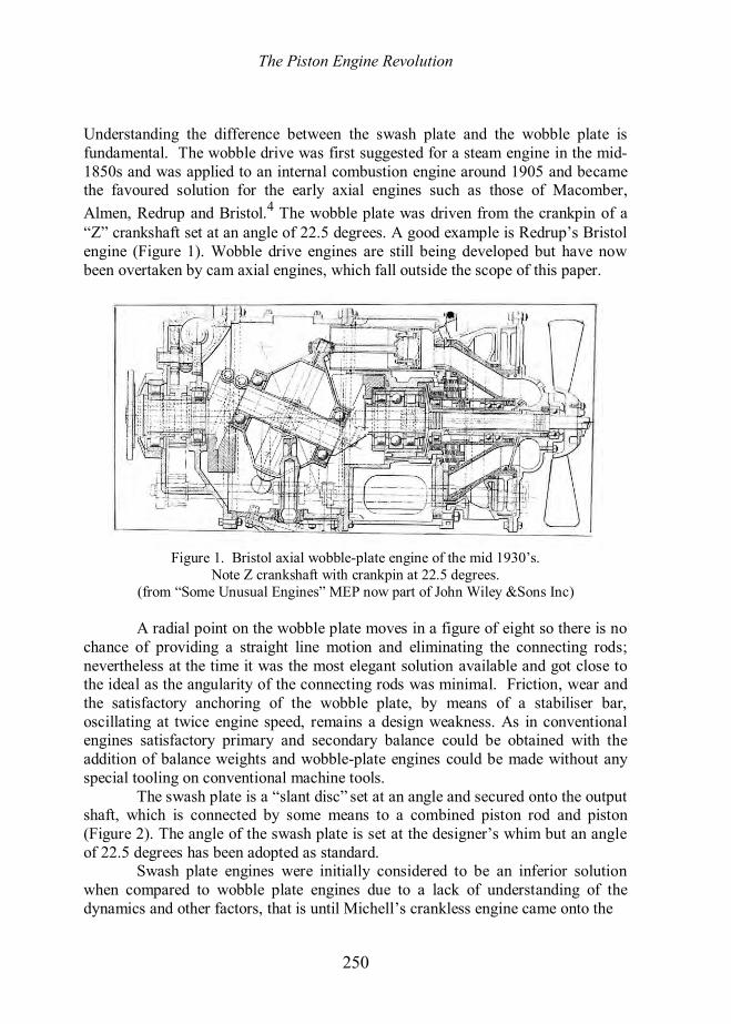
Understanding the difference between the swash plate and the wobble plate is fundamental. The wobble drive was first suggested for a steam engine in the mid-1850s and was applied to an internal combustion engine around 1905 and became the favoured solution for the early axial engines such as those of Macomber, Almen, Redrup and Bristol.4 The wobble plate was driven from the crankpin of a “Z” crankshaft set at an angle of 22.5 degrees. A good example is Redrup’s Bristol engine (Figure 1). Wobble drive engines are still being developed but have now been overtaken by cam axial engines, which fall outside the scope of this paper.
Figure 1. Bristol axial wobble-plate engine of the mid 1930’s.
Note Z crankshaft with crankpin at 22.5 degrees. (from “Some Unusual Engines” MEP now part of John Wiley &Sons Inc)
A radial point on the wobble plate moves in a figure of eight so there is no
chance of providing a straight line motion and eliminating the connecting rods; nevertheless at the time it was the most elegant solution available and got close to the ideal as the angularity of the connecting rods was minimal. Friction, wear and the satisfactory anchoring of the wobble plate, by means of a stabiliser bar, oscillating at twice engine speed, remains a design weakness. As in conventional engines satisfactory primary and secondary balance could be obtained with the addition of balance weights and wobble-plate engines could be made without any special tooling on conventional machine tools.
The swash plate is a “slant disc” set at an angle and secured onto the output shaft, which is connected by some means to a combined piston rod and piston (Figure 2). The angle of the swash plate is set at the designer’s whim but an angle of 22.5 degrees has been adopted as standard.
Swash plate engines were initially considered to be an inferior solution when compared to wobble plate engines due to a lack of understanding of the dynamics and other factors, that is until Michell’s crankless engine came onto the

The Piston Engine Revolution
251
Figure 2. Principle of crankless engine, showing a slant (swash) plate and a pair of pistons. scene, when a rigorous analytical approach was carried out, comparable to that performed on conventional internal combustion engines by the likes of Dugald Clerk, Frederick Lanchester and Harry Ricardo.
The Michell Crankless engine was a swash plate engine although it was never referred to as such by the inventor; the term swash plate is now universal and well known.5 To understand the principle of the engine and how it developed it is necessary to discuss the background to the man and how he come to develop his engine, which became an obsession for some 30 years, from 1917 until the mid-1940s. By the late 1930s his early fundamental patents had expired but those companies who wished to continue to exploit the principle, particularly for aircraft engines in the USA, retained him. The crankless engine as designed and conceived by Michell was very nearly a commercial success. Technically it was a brilliant concept and design, but this alone is not sufficient. Some possible reasons on why it failed commercially are given later.
The crankless engine as it was known was entirely the brainchild of one man, A.G.M. Michell. He is well known for the invention of the tilting pad thrust bearing for which he was granted the initial UK and Australian patents in 1905. All subsequent patents were for detailed improvements. This invention more than any other single machine element was responsible for the rapid increase in the size of hydro-electric, pumping and hydraulic machines; but by far its greatest success was in its application as a marine thrust bearing from around 1913 when its use became almost universal. Sir Charles Parsons is credited with using it for a marine application for the first time and he later used Michell bearings on land-based steam turbines.6
The principle of operation is well known although its theory is complex. In the author’s opinion it is the most elegant and simplest of all single machine elements to be invented during the twentieth century, in terms of its economic impact. The tilting pad thrust bearing has been an economic success in many applications and it has been stated that during WW1 its introduction as a standard

The Piston Engine Revolution
252
fitment on new naval builds and refits, replacing the traditional collar-box thrust bearing, saved £500m in fuel costs.7
Allowable collar box pressures (which required constant adjustment) were typically only 50 psi compared to 500 psi continuous bearing pressures on a Michell bearing, which were self-adjusting. An understanding of the tilting pad bearing (which can be applied to both thrust and journal bearings) is fundamental to an understanding of the crankless engine.
The object of lubrication is to keep moving surfaces apart with a fluid in which sufficient pressure is automatically generated to carry the load. This fundamental concept of thin film lubrication was analysed by Osborne Reynolds in Manchester in 1883-86 and his work firmly established the science of Tribology. He showed that a hydrodynamic bearing required the lubricant to be entrained into a gap between the bearing surfaces, which decreased in height (tapered) in the direction of entrainment. His theory took into account side leakage.
The near optimum taper in such a bearing was calculated to be about 1 in 1000 (3.4 minutes of arc).8 Such a fixed taper was at that time outside the limits of consistent manufacturing capability. Michell took Reynolds’ theory of thin film lubrication and developed it further by arranging for the load to be carried on a series of pivoted whitemetal pads such that the taper can vary and always be at its optimum angle according to the load and film thickness. As load is increased the film will become thinner, but provided the film of oil is always retained very high loads can be sustained. A film thickness of down to 0.001 inch (0.03mm) and a taper down to 1 minute of arc are possible even with big thrust loads. The classic formula developed by Michell is given by:-
2/p K U where p is the thrust pressure on a pad, K is a constant, µ is the viscosity of the oil (assumed constant), U is the linear speed and α is the angle of tilt of the pad.9 The above shows that the pressure on a pad varies inversely as the square of the angle of tilt. As the external load on the thrust bearing is increased the tilt angle decreases. Working pressures of up to 500 psi can be maintained at very low coefficients of friction, typically 0.001, and were recommended as normal, but under test, pressures as high as 12,000psi were maintained.10 Michell allowed for several thrust pads to pivot at the point of the centre of pressure (just behind the mid-point of the pad) and this was the basis of his patent. A series of pivoted (or ball-jointed) radial thrust pads, usually eight, form the basis of the Michell thrust bearing. The principle can also be applied to journal bearings and was used to support long propeller shafts. The tapered oil film together with a typical thrust bearing is shown in Figure 3.

The Piston Engine Revolution
253
Figure 3. Oil pressure distribution on a tilting pad and Michell thrust bearing.
Michell, the Man, and the Pre-Crankless Engine
Anthony George Maldon Michell (who was known as Anthony to his friends but as George to his family) was an Australian who was born in London on 21 June 1870, because his parents, who had emigrated from Cornwall in 1854 were visiting friends in England during their long leave after 15 years’ service in the colony of Victoria. The Michells hailed from Cornwall and Michell’s parents were of solid middle class stock. His father, John, was a mining engineer based in Tavistock, Devon and who had settled in Maldon, Victoria at one of the new gold mining areas. Like so many of his generation with a Cornish mining background he was attracted to making a fortune in the newly discovered goldfields of Victoria, which was the start of the first wave a mass immigration to Australia. Shortly after the birth of Michell, his parents returned to Australia and he grew up in both Maldon and Melbourne.
By 1884 the family were comfortably off and returned to England, for some years, because John, Michell’s elder brother, who was schooled at Wesley College, had won a scholarship from Melbourne University to Trinity College Cambridge to read mathematics. He graduated as senior wrangler and was appointed a fellow of Trinity. Michell meanwhile spent four years at the Perse school in Cambridge and then spent a year as a non-collegiate student at the university. He attended lectures on Physics given by J.J. Thomson11 and applied mechanics from Alfred Ewing.12 On the appointment of John as a lecturer in
The Piston Engine Revolution
254
mathematics at the University of Melbourne the family returned home to Melbourne.
Michell enrolled at the university and graduated with a first in architecture, civil and mining engineering in 1895 and in 1897 he obtained his Master of Civil Engineering (MCE). Michell always felt that he lacked the mathematical ability of his brother and decided on a more practical career in engineering. In due course both brothers were elected FRS.
On graduation, he joined the local engineering firm of Johns and Waygood, still in business in Melbourne, and this gave him an interest in hydraulic machinery and lubrication. In 1903 he set up in practice as a consulting engineer specialising in hydraulic machines and also qualified as a patent examiner in the Patent Office of Victoria. During 1904 he filed for the tilting pad thrust-bearing patent, which was granted in England and Australia on 16 January 1905. At this time he was appointed a designer and consultant to G. Weymouth Pty. Ltd, another Melbourne firm who made pumping and hydraulic machinery. He was asked to design two vertical spindle pumps at Cohuna on the Murray River. This was to be the first application of the Michell thrust bearing. Just when Michell stumbled on his “eureka moment” is not recorded. It must have been sometime in late 1903 or early 1904 but he had to wait until 1907 before the Cohuna installation was completed and the success of the bearing was proven. From this moment Michell never looked back.
At this time it must be mentioned that Professor Albert Kingsbury (1863 -1943), an engineer working for the Westinghouse Electric Company, quite independently of Michell developed a tilting pad thrust bearing similar to that of Michell but with slight detail differences. He made a model while employed as an academic in 1897 before joining Westinghouse but did nothing with it as there was no requirement. The Pennsylvania Water and Power Co were in need of a new thrust bearing at their Holtwood Hydro Station and sought the help of Westinghouse.13 Kingsbury was approached and remembering his earlier experiments designed a tilting pad bearing and filed for a patent in the United States in 1907. He was finally granted Patent No 947,242 in 1910.
The delay in the grant was because of objections based on Michell’s patent which covered the UK and Australia. It was a classic example of “coincident invention” as neither party had any prior knowledge and were working entirely independently. As ever, the lawyers got to work, which caused Michell much distress before a settlement was reached. Both Michell and Kingsbury had enormous respect for each other and their respective common interests and neither wanted any infringement litigation so it was mutually agreed that in the United Kingdom, Commonwealth and Europe it would be called a “Michell” bearing while in the United States and South America it would be called a “Kingsbury” bearing and these names continue to this day.

The Piston Engine Revolution
255
From 1911 the Michell bearing was promoted in the United Kingdom by his business partner Mr H.T. Newbigin and by the start of World War I the partnership had negotiated several licence agreements in the United Kingdom as well as a number European countries, including Germany who incorporated the bearing on U boats and new ships for the High Seas Fleet. In 1920 the Michell Bearing Company was formed in Newcastle on Tyne.14 It is still located in the city close to the site of the old Armstrong-Whitworth works at Elswick. Figure 4 shows one of the few known pictures of Michell.
Figure 4. Only known photograph of Anthony Gearge Maldon Michell, FRS
(1870-1959)
The Crankless Engine Period By 1917 Michell, now resident in Melbourne, was a relatively wealthy man from royalties and was looking for an additional application for the tilting pad bearing. Because of his existing interest in pumps he first designed a crankless compressor the key element of which was a rotating slant plate (swash plate) and a series of radial tilting slipper pads, one for each cylinder. Between 1917 and 1938 a search of the British patent specifications shows that some 19 patents were granted for the crankless engine, the fundamental patent being for the conversion of rotary into linear motion and vice-versa. The specification for the fundamental patent for the crankless engine was very comprehensive and covered all likely future uses of the crankless mechanism. A partial list includes: all forms of steam engines; all forms
The Piston Engine Revolution
256
of IC engines; compressed air engines; pumps; air and gas compressors; blowers for blast furnaces; vacuum and tyre pumps; transmission systems; and fluid meters. Some of these applications were anticipated but did not come to fruition until expiry of the 20-year term of the patent.
Because of the very low coefficient of friction (as low as 0.001) Michell used to demonstrate that even with a slant angle down to 1 degree conversion to rotary motion was still possible. In practice, provided the instantaneous slant angle is always greater than the angle of friction (tangent of the coefficient of friction, typically 4 minutes of arc) conversion to rotary from linear motion is possible. An analysis of the reversibility of a slant disc is given in Appendix A.
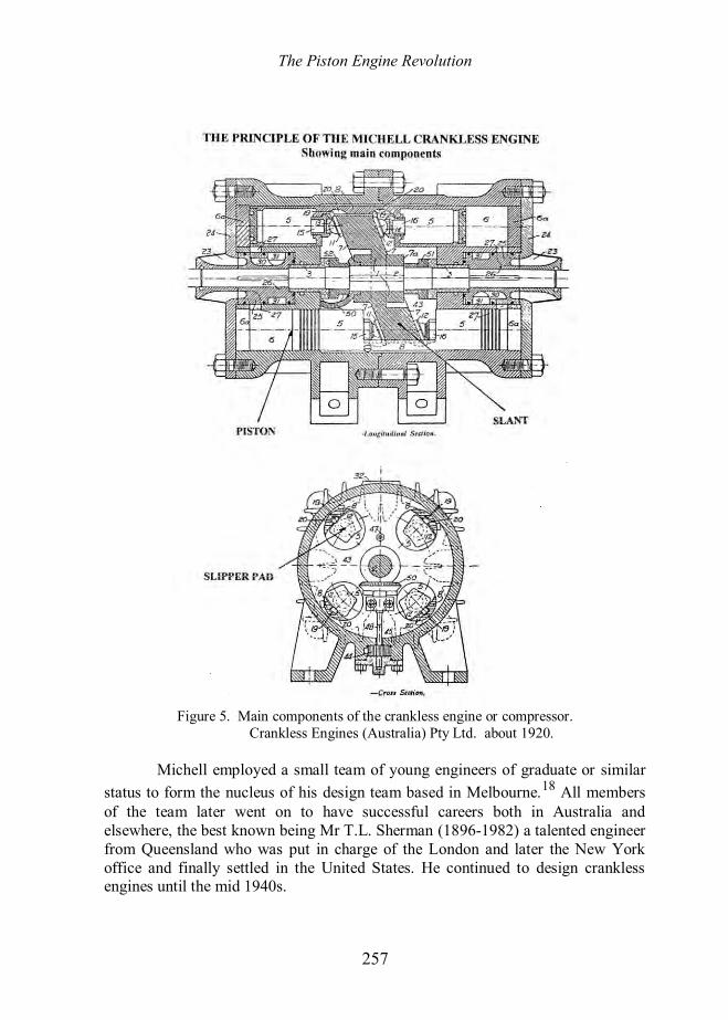
Michell perfected the design for a crankless compressor; a typical cross-section being illustrated in Figure 5. This shows an eight-cylinder unit with the slipper pads mounted in ball sockets that can be adjusted to give the correct clearance. This became a feature on all crankless designs. Michell was able to show that by choosing certain dimensional proportions with reference to the weight of the slant and pistons, perfect balance at all speeds was possible. He claimed smooth running comparable to that of a turbine without any external couples provided that two or more cylinders are used.15 The equation to achieve perfect balance in given in Appendix B. An early compressor was installed in a gas works and the prototype has survived.
As a result of this smooth running and reversibility, Michell then made a uniflow steam engine16 but his real objective was to make an internal combustion engine. This was the next logical progression and a prototype engine was built. The addition of poppet valves, push rods, a camshaft and sparking plugs was an easy step. One of the first engines sold was an eight-cylinder (two opposed four-cylinders) 750 rpm, 70 hp gas engine and was supplied to a company in Sydney.17 No drawings, technical details or performance figures of the prototype crankless engine appear to have survived but it would have been made around 1919-20. Michell, however, was sufficiently encouraged by the performance of this engine that he formed Crankless Engines (Australia) Pty Ltd, which was incorporated in Melbourne on 24 August 1920. The name was changed to Crankless Engines Limited on 6th March 1922 when it converted to a public company with an issued capital of £100,000. Prior to this time Michell himself, from royalties from the tilting pad bearing, and some friends had funded the company. The initial office and workshop of the company was at 129 Greeves Street, Fitzroy, an inner Melbourne suburb, after which the company design office was based at Henty House, 499-503 Little Collins Street, Melbourne, although the workshop facilities remained in Greeves Street, Fitzroy. The long-term objective was that the company should be a design and R&D organisation and that licensing agreements would be negotiated for manufacture with suitably qualified companies.
The Piston Engine Revolution
257
Figure 5. Main components of the crankless engine or compressor.
Crankless Engines (Australia) Pty Ltd. about 1920.
Michell employed a small team of young engineers of graduate or similar status to form the nucleus of his design team based in Melbourne.18 All members of the team later went on to have successful careers both in Australia and elsewhere, the best known being Mr T.L. Sherman (1896-1982) a talented engineer from Queensland who was put in charge of the London and later the New York office and finally settled in the United States. He continued to design crankless engines until the mid 1940s.
The Piston Engine Revolution
258
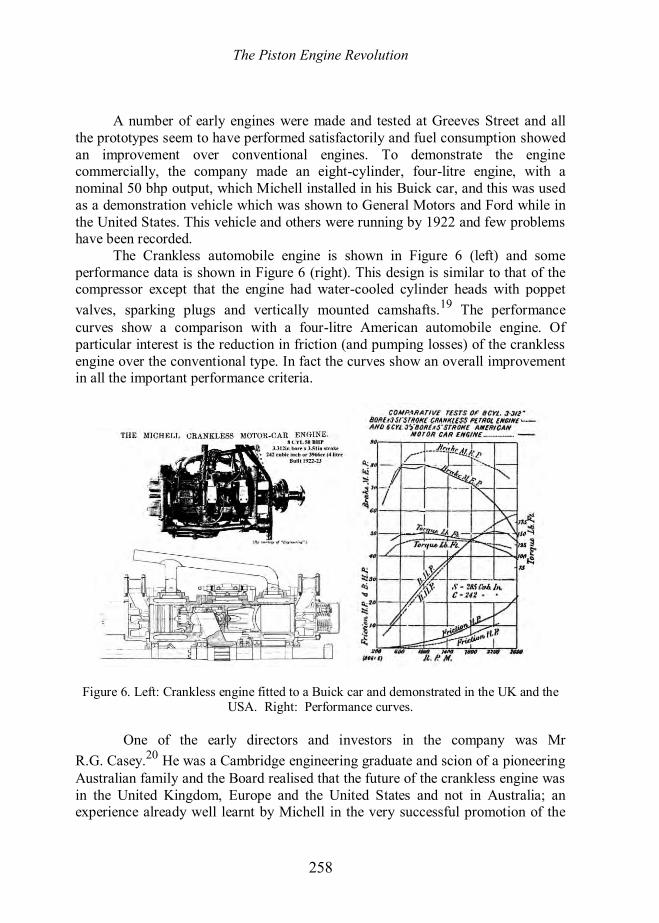
A number of early engines were made and tested at Greeves Street and all the prototypes seem to have performed satisfactorily and fuel consumption showed an improvement over conventional engines. To demonstrate the engine commercially, the company made an eight-cylinder, four-litre engine, with a nominal 50 bhp output, which Michell installed in his Buick car, and this was used as a demonstration vehicle which was shown to General Motors and Ford while in the United States. This vehicle and others were running by 1922 and few problems have been recorded.
The Crankless automobile engine is shown in Figure 6 (left) and some performance data is shown in Figure 6 (right). This design is similar to that of the compressor except that the engine had water-cooled cylinder heads with poppet valves, sparking plugs and vertically mounted camshafts.19 The performance curves show a comparison with a four-litre American automobile engine. Of particular interest is the reduction in friction (and pumping losses) of the crankless engine over the conventional type. In fact the curves show an overall improvement in all the important performance criteria.
Figure 6. Left: Crankless engine fitted to a Buick car and demonstrated in the UK and the USA. Right: Performance curves.
One of the early directors and investors in the company was Mr
R.G. Casey.20 He was a Cambridge engineering graduate and scion of a pioneering Australian family and the Board realised that the future of the crankless engine was in the United Kingdom, Europe and the United States and not in Australia; an experience already well learnt by Michell in the very successful promotion of the

The Piston Engine Revolution
259
Michell thrust bearing. Accordingly, the company opened a London office based at 20 Grosvenor Gardens, close to Victoria Station, under the able management of T.L. Sherman.
His responsibilities were as a salesman promoting the principles and as a design engineer as he had sufficient technical knowledge to be able to design to the project stage, such that it was not necessary to promote the Australian pedigree, and all design work, working drawings and manufacture could be done locally out of the London office. Meanwhile Casey was duly despatched to the United States via the United Kingdom as the salesman on the demonstration tour; the full report of his visit has not as yet been located. Over fifty years later, as Lord Casey, he tells of his initial meeting with Michell:
Michell also produced and patented what he called a ‘crankless engine. This brought him to a small group of which I was one, who were interested in mechanical things immediately following the end of the 1914-18 war. It took us some little to get into Michell’s confidence, but eventually, we did, as a result he asked me if I would consider taking a motorcar with his crankless engine to the United States to demonstrate it to General Motors, Ford etc. The small group formed a small company designed to organise and finance this expedition and I was asked to go to America in 1921 with a crankless car and a mechanic. I did so and complete tests of several weeks each were carried out at the General Motors research establishment at Dayton, Ohio and by the Ford Motor Company at Detroit, Michigan. In each case, the companies told me that the bench tests showed that the crankless engine was something like 10% more efficient than the current orthodox car engine, but ten per cent improvement was not enough to warrant the very large capital investment involved in re-tooling for the manufacture.21
He makes no mention of his prior demonstration tour of the United Kingdom but from all accounts the demonstrations were well received by the motoring press. Nevertheless no major automobile manufacturer was prepared to take on board such a revolutionary new concept.
One of the companies visited with the demonstration car was The Steel Products Engineering Company (Speco), Springfield, Ohio, later a division of the Kelsey-Hayes group. Speco was a major supplier of components for the motor industry and later entered the aero engine and aircraft component industry. They gave serious thought to entering the engine market via the crankless engine and kept a close liaison with crankless engine developments and later with the American company, Crankless Engine Corporation of New York, that was later managed by Mr Sherman. He finally became an employee of Speco. Sherman was responsible for the design of all the Speco/Michell crankless aero engines made from 1929 right through to WWII as chief designer during which time he continued to maintain a close liaison with Michell in Australia. The whereabouts of the
The Piston Engine Revolution
260
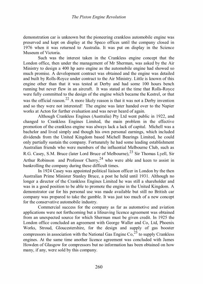
demonstration car is unknown but the pioneering crankless automobile engine was preserved and kept on display at the Speco offices until the company closed in 1976 when it was returned to Australia. It was put on display in the Science Museum of Victoria.
Such was the interest taken in the Crankless engine concept that the London office, then under the management of Mr Sherman, was asked by the Air Ministry to design a 400 hp aero engine as the automobile engine had showed so much promise. A development contract was obtained and the engine was detailed and built by Rolls-Royce under contract to the Air Ministry. Little is known of this engine other than that it was tested at Derby and had some 100 hours bench running but never flew in an aircraft. It was stated at the time that Rolls-Royce were fully committed to the design of the engine which became the Kestrel, or that was the official reason.22 A more likely reason is that it was not a Derby invention and so they were not interested! The engine was later handed over to the Napier works at Acton for further evaluation and was never heard of again.
Although Crankless Engines (Australia) Pty Ltd went public in 1922, and changed to Crankless Engines Limited, the main problem in the effective promotion of the crankless engine was always lack a lack of capital. Michell was a bachelor and lived simply and though his own personal earnings, which included dividends from the United Kingdom based Michell Bearings Limited, he could only partially sustain the company. Fortunately he had some leading establishment Australian friends who were members of the influential Melbourne Club, such as R.G. Casey, S.M. Bruce (later Lord Bruce of Melbourne),23 Sir Thomas Lyell, Sir Arthur Robinson and Professor Cherry,24 who were able and keen to assist in bankrolling the company during these difficult times.
In 1924 Casey was appointed political liaison officer in London by the then Australian Prime Minister Stanley Bruce, a post he held until 1931. Although no longer a director of the Crankless Engines Limited he was still a shareholder and was in a good position to be able to promote the engine in the United Kingdom. A demonstrator car for his personal use was made available but still no British car company was prepared to take the gamble. It was just too much of a new concept for the conservative automobile industry.
Commercial success for the company as far as automotive and aviation applications were not forthcoming but a lifesaving licence agreement was obtained from an unexpected source for which Sherman must be given credit. In 1925 the London office concluded an agreement with George Waller and Co, Ltd, Phoenix Works, Stroud, Gloucestershire, for the design and supply of gas booster compressors in association with the National Gas Engine Co,25 to supply Crankless engines. At the same time another licence agreement was concluded with James Howden of Glasgow for compressors but no information has been obtained on how many, if any, were sold by this company.

The Piston Engine Revolution
261
This was a remarkable achievement and just the incentive that the London based subsidiary and the Australian parent company needed. George Waller and Co Ltd was founded in 1850 and made steam engines. By the 1920s they had built a reputation for the supply of gas compressors and boosters. The supply of crankless gas boosters built under licence was very successful for the company and the last order for a Waller crankless compressor for the Admiralty was received as late as 1971. Not all these Waller made crankless gas compressors and boosters were coupled to crankless engines made by the National Gas Engine Co. The total number made is not known but in the early 1970s the late Mr W.S.B. Hall, the then retired Technical Director of George Waller, prepared a Schedule of Michell Crankless machines supplied from 1925, totalling approximately 116. Of these some twenty were supplied with crankless engines made by National Gas Engine Co but the company records appear to have been lost. Details of the Michell Crankless Gas Engines and Boosters supplied under licence by George Waller and the National Gas Engine Co Ltd were described in an article in Gas Journal (Figure 7).26 Only one Michell-National Gas engine is known to have survived and is in the Powerhouse Museum in Sydney.
It is ironic that many of the early gas booster machines were exported to Australia from the United Kingdom, but the largest customer for crankless compressors was the Admiralty who accounted for rather more than 50% of the machines made by George Waller.27 The End of the Beginning Sadly the royalties received from George Waller and the National Gas Engine Co., were not sufficient to keep the parent company going and as no other revenue-earning licence agreements appear to have been concluded, the axe fell and in February 1928 the banks withdrew their support.
In Australia the depression was beginning to be felt and as manufacturing and engineering were a relatively small part of the economy the company was vulnerable. The handpicked small and talented staff was made redundant and all found new employment. Michell himself saw the future of the crankless principle not in Australia but in the USA where he spent the next three years. He based himself at the New York office, which managed to remain trading as a separate entity as the Crankless Engine Corporation under the management of T.L. Sherman, concentrating on the design and development of crankless engines for aircraft in association with Speco. In 1934 Michell returned to Australia and resumed his work as a consulting engineer based in Melbourne, the same year that he was elected FRS.
In 1929 Speco built for the US Navy a twelve-cylinder crankless 800hp, 2500 rpm aero engine designed by Sherman under the supervision of Michell. It had a compression ratio of 5.4 to 1. The dry weight per hp was 1.65lb, which

The Piston Engine Revolution
262
Figure 7. Crankless gas booster made by George Waller, and a gas engine by National Gas
Engine Co. Ltd. compared favourably with any of the contemporary conventional aero engines, Figure 8. It is not known in which aircraft (if any) it was installed nor how many prototype aero engines Speco later made.
The sad part of the story is that on closure of the Melbourne design office and workshop all company records, many drawings and prototypes appear to have been destroyed or disappeared. It is still possible that artefacts may still come to light after 80 years or more. But the question remains what really did go wrong and why was the crankless principle not more widely adopted as an internal combustion engine?
Why did not Michell realise his dreams? The company was promoting a mechanism which was proven to be at the time, and still is, the most efficient yet devised for the conversion of reciprocating movement into rotary movement and

The Piston Engine Revolution
263
Figure 8. Michell crankless 12-cylinder aero engine. Compression ratio 5.4:1, 800 hp at 2500 rpm. Dry weight 1.651 lb per hp. First built 1929, modified 1943 for US Navy by
Speco, Springfield, Ohio. Now in Smithsonian Institution, Washington DC.
vice-versa. It is a mechanism that can be perfectly balanced for all speeds. Having fewer parts its production costs should have been less than or certainly equal to that of a conventional reciprocating machine. Its weight and power density were superior.
The fact that it was of Australian pedigree, a far off country, still yet to shrug off its colonial past, possibly had much to do with it, yet it was well promoted in both the UK and US within the financial constraints. The company was always undercapitalised, financed largely by Michell himself and his friends. He and his loyal and talented colleagues tried to do just too much with too little.
It was not until 1927 that any real revenue was earned from the royalties from the big gas-engine driven boosters that went into production in England. Representation in London and New York was largely a one-man operation in spite of the personnel being selected for both engineering and commercial ability. Perhaps the company spread its limited resources too thinly and was (to use modern business speak) not focused. The view of the author is that the internal combustion engine and the reciprocating compressor were well understood and were just too deeply entrenched by the well-established manufacturers who were already tooled-up and had invested heavily in new plant after WW1. So why change? The economic benefits of the crankless engine were seen as no more than marginal in spite superior technical performance. One also detects something of the “not invented here” syndrome.
The Piston Engine Revolution
264
The forthcoming worldwide depression was another factor against its success. After the original patents had expired the crankless principle found application in small hydraulic motors and fuel pumps used in particular by the aircraft industry. In 1934, Michell set up in practice in Melbourne as a consulting engineer working on lubrication and hydraulic problems for which he now had a worldwide reputation. The Crankless Engine Company Limited was maintained as a shell company registered in Melbourne and was not finally liquidated until June 1946.
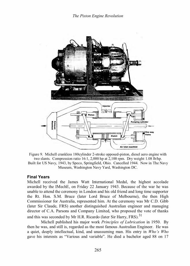
In 1942, while Sherman was working for Speco, the company received two important Navy contracts for the design, testing and supply of crankless aero engines. One was for an updated and improved version of the 800 hp engine first designed in 1929 and for a very advanced Michell/Sherman designed 18-cylinder opposed-piston 2000 hp two-stroke, uniflow scavenged, crankless, diesel aero engine with dual slants (Figure 9).28 Sadly, development work on this and other new designs for advanced, highly-rated internal combustion aero engines had virtually ceased by the end of 1944 because of the success of the turbo-jet engine which was seen as the propulsion unit for the future, although existing proven engines continued to be developed for some years, both in the United States and United Kingdom.29 The Lucas Fuel Pump But this is still not quite the end of the story and brief mention must be made of another Australian, a disciple of Michell, and who had made a study of crankless engines, the design of which he adapted for a high pressure fuel pump. Richard Joseph (Dick) Ifield (1914-83) was a self-taught innovative engineer who had applied for a patent around 1938 for a variable stroke swash plate high-pressure pump.
At the age of 21 he arrived in England and got his first job working for the Riley Car Company in Coventry until it went into liquidation in 1938. He then joined the Joseph Lucas Group in 1940, his patent application having come to the notice of the then Group Chief Engineer, Dr E.A Watson, who recommended to the chairman, Mr Oliver Lucas, that he should interview the applicant for a job, as the design of the pump was ideal for the fuel system for the Whittle turbo-jet engines. These engines were built by BTH (British Thomson-Houston) for Power Jets and later by Rover, for which Lucas had been contracted to design and build the fuel and combustion system.
By 1947 Ifield had become chief engineer. Lucas fuel pumps and equipment had become world famous and very successful, having been adopted by Rolls-Royce, de Havilland, Armstrong-Siddeley and Bristol. Ifield returned to Australia for family reasons in the late 1940s and was appointed managing director of the Lucas subsidiary in Australia.30
The Piston Engine Revolution
265
Figure 9. Michell crankless 180cylinder 2-stroke opposed-piston, diesel aero engine with
two slants. Compression ratio 16:1, 2,000 hp at 2,100 rpm. Dry weight 1.08 lb/hp. Built for US Navy, 1943, by Speco, Springfield, Ohio. Cancelled 1944. Now in The Navy
Museum, Washington Navy Yard, Washington DC. Final Years Michell received the James Watt International Medal, the highest accolade awarded by the IMechE, on Friday 22 January 1943. Because of the war he was unable to attend the ceremony in London and his old friend and long time supporter the Rt. Hon. S.M. Bruce (later Lord Bruce of Melbourne), the then High Commissioner for Australia, represented him. At the ceremony was Mr C.D. Gibb (later Sir Claude, FRS) another distinguished Australian engineer and managing director of C.A. Parsons and Company Limited, who proposed the vote of thanks and this was seconded by Mr H.R. Ricardo (later Sir Harry, FRS).31
Michell published his major work Principles of Lubrication in 1950. By then he was, and still is, regarded as the most famous Australian Engineer. He was a quiet, deeply intellectual, kind, and unassuming man. His entry in Who’s Who gave his interests as “Various and variable”. He died a bachelor aged 88 on 17

The Piston Engine Revolution
266
February 1959 at his flat, 413 Collins Street in Melbourne. From 1915 he lived with his sisters in the family home, Camberwell, a leafy Melbourne suburb, where he had his extensive library and kept his personal papers.
As well as being an engineer he was also a landowner, gardener, environmentalist and philosopher. Sadly some time before he died it was suspected that he was starting to gradually lose his mental faculties and he is said to have destroyed many of his personal papers which was a great loss and no doubt with it went much unpublished information on the crankless engine and performance data. Where Have all the Engines Gone? As far as is known there are no preserved Michell Crankless Engines in the United Kingdom, so one has to travel far to see any of the six preserved engines and large compressors which are known to exist. The Powerhouse Museum in Sydney has an early eight-cylinder 70 hp compressor engine as well as a Michell-National Gas engine, which is awaiting restoration. The Engineering Department at Melbourne University has a sectioned compressor in its hydraulics department. The four-litre car engine, which went to the United Kingdom and United States in 1922 in the demonstration car, is believed to be currently on display in the main foyer of the engineering building at Melbourne University, on loan from the Science Museum of Victoria. Of the Speco, Sherman-designed experimental aircraft engines built from 1929 until the end of WW2, an example of the 800hp version is in the Smithsonion Institution in Washington DC while the 2000 hp diesel aircraft engine built for the US Navy is in the Navy Museum, also in Washington DC. It is possible that additional examples will be found and it is surprising that none of the National Gas Engine - Waller complete combination sets appears have been preserved. The last was not finally taken out of service until 1957 and subsequently scrapped.
But the real mystery remains. What happened to all the drawings, company records, engines and experimental units which were in the offices in Collins Street and the workshop at Fitzroy, Melbourne when the receivers moved in on Crankless Engines Limited in 1928? It is just possible that somewhere they have been safely hidden and may yet appear at some obscure location. Apart from the automobile engine known performance figures the only other is a test on a 100HP crankless gas engine for the Australian Gas Light Company by a Sydney-based firm of consulting engineers in June 1925 and a summary is given in Appendix C.32
Conclusions Based on the evidence of the number engines and compressors sold, the Michell Crankless engine was and remains the most successful of all the axial internal combustion engines. Its competitors using the wobble plate suffered from early development problems, which, if given the financial resources, would have been
The Piston Engine Revolution
267
technically soluble, but they were never satisfactorily concluded to give a long lasting and reliable engine.33
The slant disc using the tilting pad thrust bearing as designed by Michell has proven to be the most efficient method of converting linear into rotary motion and vice-versa. On test the 1922 automobile engine was shown to have had a fuel consumption improvement over the then conventional engines of 10%. With a programme of continual development who can say that this performance differential would not have been maintained when compared with the modern direct injection common rail diesel engines of today?
The power-to-weight ratio would have been steadily improved and the comparison with conventional engines would, no doubt, have been maintained. Likewise the lower parts count for the same number of cylinders compared with a conventional engine would have been maintained. It had much going for it and more Michell crankless engines were sold during the period under review compared with any other type of axial engine. So why was it not a commercial success? Summary of advantages
Used the most efficient means of converting linear to rotary motion. No special manufacturing skills needed. Lower parts count. Fewer moving parts to fail. Less maintenance. More fuel-efficient and hence lower running costs. Perfect balance over complete speed range. Smaller frontal area in aircraft engine compared with radial and in-line designs. Higher power density. Cost of manufacture comparable with or lower than conventional engines. All unforeseen future technical failings (and there were bound to be some) could be corrected by development, as the design was both sound and simple.
The rather feeble maintenance cost disadvantages, which were argued both in the UK and USA, are that the radiator of the car had to be removed to gain access to the front cylinder heads and access to the back cylinder heads was always restricted. This was at a time when constant tappet adjustment and decarburising (decoking) was required as a matter of routine. Hardly sound reasons for not making an investment decision. If engine access for maintenance was a problem then why not design for easy engine removal? This is now common practice.

The Piston Engine Revolution
268
Michell however took this objection seriously and made a five-cylinder single ended engine that was fitted to an Austin 12 car. The ultimate whereabouts of the car is unknown; it remained in Australia after the demise of the company. Some suggested commercial reasons for failure
Seen as an Australian invention, from a country still regarded as an outpost of Empire, where innovation and manufacturing were still in the embryo stage. Always underfunded. No government support. Young, enthusiastic well-qualified team of engineers with little or no commercial experience Lack of focus. Trying to do too much too quickly with only limited resources. Potential licensees such as the major automobile makers (GM, Ford etc) not prepared to reinvest in new tooling for quantity production. The fuel savings due to increased engine efficiency were insignificant against the then prevailing low price of fuel. Worldwide recession of the late 1920s and early 1930s was looming. The conventional IC engine was already well established and on the ascendancy, so why change? Lack of a hard sales approach. Both London and New York offices strong technically but understaffed in marketing and sales. “Not invented here” syndrome. The project never found a true Product Champion (it probably got very close with the Speco Division of Kelsey Hayes) Possibly 10-20 years too late?
The Michell Crankless Engine deserves its place in the history of the internal combustion engine during the first half of the twentieth century. It was the most successful of all the unconventional engines. The high-pressure, variable-stroke swash plate fuel pump, which was a direct descendant, played a significant role in the development of the turbo-jet engine worldwide from the 1940s. Appendix A Proof of reversibility of a slant disc using a tilting pad bearing to give rotation.34 Let:- µ = coefficient of friction, typically 0.001 but assume as 0.002. θ = the instantaneous angle of an element of the slant over which sliding is taking place. F = force applied at the slant by the piston as an engine or to the piston as a compressor

The Piston Engine Revolution
269
ηm= efficiency as a crankless engine ηc = efficiency as a crankless compressor Resolving forces tangentially in the direction of rotation we get:-
1 (tan cot )m and
11 (tan cot )c
Expanding ηc we get 2 21 (tan cot ) (tan cot )c
Note that efficiency difference between a compressor and crankless engine, is no more than ﴾µ(tanθ+cotθ)﴿2. Assuming a slant of 22.5 degrees then θav is 11.25 degrees, thus tan θav = 0.1989 and cot θav = 5.0276 for a complete revolution, and taking μ=0.002 then the difference is only 0.00010926, or about 1/10 of 1% in favour of the compressor, which is negligible. Note that this reversible efficiency difference for either the compressor or the crankless engine is independent of the force F applied at the slant to the piston. Appendix B There is a couple generated by the reciprocating pistons and rods. This can be balanced by an equal and opposite couple generated by the slant disc if its mass is chosen to be32:-
2
2 2
2nmRMA a
where: M = mass of the slant disc n = number of piston rods (ie number of pairs of pistons) m = mass of each piston rod (ie a pair of pistons) R = Radius (from the axis of rotation) to the centre line of a piston rod A = outer radius of the slant a = radius of the slant shaft (output shaft) on which the slant is mounted Note that balance is not a function of the slant angle. Appendix C Summary of test report on a 100 H.P Crankless Gas Engine Carried out by Messrs Julius, Poole & Gibson, Consulting Engineers, 906 Culwulla Chambers, Castlereagh Street, Sydney, 26 and 27 June 1925.
The Piston Engine Revolution
270
Test was carried out at the works of: Crankless Engines Limited, Greeves Street, Fitzroy, Melbourne, for and on behalf of Australian Gas Light Company. Engine: four-stroke Otto cycle, eight-cylinder, 5½” bore by 6½” stroke. Compression ratio 5.7:1. Coupled to Froude Dynamometer. The following average results were obtained at 750RPM:- BHP 112.5 100 IHP 125.0 112.2 (Thompson optical indicator used) ηmech % 90.0 89.3 ηthermal % 28.0 26.8 Note. Large gas engines (typically >1000hp) supplied by National Gas at the time quoted a ηmech of c88% and a ηthermal of c28%. For a copy of the complete report please contact the author. Notes and References1. L.J.K. Setright Some Unusual Engines (Mechanical Engineering Publications, now part of John Wiley & Sons. Inc, 1931-2005), p. 99. Setright was a lawyer and well-known motoring journalist whose eloquence sometimes exceeded his technical knowledge. 2. From Ingenious Mechanisms for Designers and Inventors, 13th edition, Franklin D. Jones, ed., (Industrial Press Inc New York, 1968), Vol. 1, p. 260. 3 Hon C.A. Parsons, British Patent no 6735, 1884. 4. Details of these engines and others can be found via a web search eg. “axial internal combustion engines”. For history on the Bristol axial engines see William Fairney The Knife and Fork Man: The life and works of Charles Benjamin Redrup (2009) ISBN 978-0-9554455-2-1. 5. First use of “swash plate” not known It is now mainly associated with helicopter cyclic pitch control. ”Slant disc” was coined and used only by Michell. 6. Sir Charles Parsons used the bearing for early experiments with a geared marine turbine during 1910/11. He introduced Michell to C.T. Newbigin c1910. British merchant ships adopted the bearing from 1913 and the Royal Navy from 1914. 7. Duncan Dowson, History of Tribology (Mechanical Engineering Publications 1998 ISBN 1 86058 070 X now part of John Wiley & Sons. Inc), p.660.
8. Ibid pages 333-341 for explanation on thin film theory. For a biography of Osborne Reynolds see pages 619-627. 9. ‘The lubrication of plain surfaces’ Zeit.f.Math.u.Phys 52B and 2 Heft (1905). 10. H.S. Broom comments on Newbigin’s paper. Proc.Inst C.E 196, p. 255. 11. J.J. Thomson (1856-1940) Professor of Physics and Master of Trinity College OM FRS and Nobel Laureate. 12. Alfred Ewing (1856-1935) Professor of Applied Mechanics and Mechanism FRS. 13. A plaque was erected at Holtwood Hydroelectric Station in 1987 by ASME commemorating the seventieth anniversary of the first installation of a Kingsbury bearing in the United States. 14. The company was incorporated on 21 May 1920. 100.000 £1 shares taken up as follows:- Michell 29,500, Newbigin 20,500, Vickers 15,000, Cammell Laird 15,000, John Brown 10,000 and Fairfield 10,000. It became wholly owned by Vickers in 1969 and in 1999 part of Rolls-Royce Marine. 15. For a complete analysis of crankless engine balancing see The Handbook of the Crankless Engine (1922), Appendix 1. 16. See Engineering 11 March 1921, p. 220. 17. This is in the Powerhouse Museum Sydney. Catalogue number B1602. 18. See Sydney Walker, Modest Man of Genius (printed privately 1972)..

The Piston Engine Revolution
271
19. For a report on this engine see Engineering 5 October 1923. 20. Richard Gardiner Casey (1890-1976) later the Right Honourable Lord Casey of Berwick KG, GCMG, CH, DSO, MC, KStJ, PC, sixteenth Governor-General of Australia. 21 Melbourne Herald 9 January 1973 22. Rolls-Royce Heritage Trust, Derby A.A.Rubbra, a former technical director in correspondence with Sydney Walker (1964) mentioned that he was in the development department at the time. 23. Stanley Bruce (1883-1967). Prime Minister of Australia.1923-29. Later Lord Bruce of Melbourne. Anglophile 24. Professor of Applied Mathematics. Melbourne University on the retirement of Michell’s brother John. 25. The National Gas Engine, Wellington Works, Ashton-under-Lyne, was founded in 1890 by Henry Bickerton to make gas engines to run on town gas. Supplied to cotton mills as an alternative to steam power. Taken over by Mirrlees, Bickerton and Day in 1932, a firm in which Henry Bickerton was also a director. 26. This article formed the basis of The ‘Michell Crankless Gas Engines and Boosters (a sales brochure, 1927) a copy of which is in the possession of the author.
27. Op. cit., Walker.Appendix 17 27.Compared with the 0.933 claimed for the Rolls-Royce Crecy, 12-cylinder sleeve valved two-stroke engine under development at the same time. Figure from data given in R-R Heritage Trust Historical Series No 21. 29. Some examples in the UK being the Bristol Centaurus, Rolls-Royce Griffon, Eagle, Napier Sabre and Nomad. 30. An account of Richard Ifield and fuel pump is told in Harold Nockolds, Lucas. The first Hundred Years, Vol. 2 (David and Charles 1978). A son is the sixties pop- singer, Frank Ifield, ‘I remember you’. 31. Proc. I.Mech.E. (January 1943). 32. A typed original copy of this report is now in the National Gas Engine archives held at the Anson Engine Museum, Poynton Cheshire SK12 1TD. The author is grateful to the curator, Mr Geoffrey Challinor, for bringing this to his attention. 33. G.W. White, ‘The Bristol Wobble Plate Engine’ in Unusual Engines Old and New (I.Mech.E. half-day symposium 7 Dec 1971). 34. A.G.M. Michell, The Crankless Engine Handbook 1st Edn. (Crankless Engines (Australia) Pty Ltd. Melbourne, 1922)
Acknowledgements I am grateful to and wish to thank the many individuals and organisations for their help in the preparation of this paper. In particular: Mrs Dianne Boddy of Melbourne, the 2010 recipient of the prestigious Michell Award; Mr Derek Ravenscroft of Castlemaine, Victoria; Mr Ian Izon of Howlong, NSW; the Western Australian Branch of the IEAus in Perth and Mr Keith Moore, librarian of The Royal Society; the library staff of the IMechE. Notes on Contributor John Anning graduated from Clare College Cambridge, where he read Mechanical Sciences. After a graduate apprenticeship at C.A. Parsons & Co Limited Newcastle-upon-Tyne he joined the project design office where he was involved in the design and performance prediction of steam turbo-generators. After some years he did a postgraduate year at The College of Aeronautics, Cranfield (now Cranfield University). He spent 14 years in Australia and worked for Babcock International Limited and ended as managing director of a group subsidiary company. Has had a

The Piston Engine Revolution
272
life long interest in engineering with a special interest in heat engines, machine tools, railways, aircraft and horology. A FIMechE, he has been a member of the Newcomen Society since 1982. Correspondence to: John Anning. Email: [email protected].