GNM( 2021 1 —l OlëO-|Xl cHðã10-lI Anthony William Fairbank ...
July 2009
Prepared for :The Newtok Traditional Council and The Newtok Planning Group
Prepared by:The Cold Climate Housing Research Center
PO Box 82489 Fairbanks, AK99708
(907) 457-3454
DESIGN ANALYSIS REPORTSCHEMATIC (35%) DESIGN
THE MERTARVIK EVACUATION CENTER

This page intentionally left blank

StanleNewto Dear S ThankMertaestablwith tensurethat wthe sisubsis This pprovidapproenergsurroupeoplcommaddre In ordinvolvpiece.constrreflectopiniointent The CNewtoprojecNewto
Sincer
Jack HPresid
P.O. Box 824
ey Tom, Tribal ok Traditional
Stanley & Sally
k you for provrvik evacuatiolishment of ththe traditions e the project’s
will one day sute, the locatio
stence resourc
project is mucded a great op
oached. The rey, affordabilit
unding sustaine of Alaska t
mitted commuss universal ch
er to make thevement is mai As this projruction of the ts that kind oon. Force accot to keep the c
old Climate Hok Traditionalct becomes suok make Merta
rely,
Hébert dent/CEO
CCHRC489, Fairbank
AdministratorCouncil
y,
viding us the oon center. It ishe new village
of the Yup’iks success. The urround it. A hon of the oth
ces, needs to b
ch more than pportunity to cealities Newtokty, a changinnability are facthat is uniquenity members
hallenges.
e practical parntained betwject moves foevacuation ce
of engagemenounting and aosts as low as
Housing Resea Council and ccessful. What
arvik their new
C Internet Wks, AK 9970
r Sally
opportunity tos our intentione in Mertarvik
k people that building as prolistic approa
her buildings, e carefully inte
simply designcreate a paradk is confrontin
ng environmeced by every ie. Working tos of Newtok, t
rts of this projeween all stakeh
orward, they enter as well as
t. The prelima close relationpossible, will b
rch Center loothe Newtok
t an honor it ww village.
Web Site: http8 Phone: (9
y Russell Cox, PNewtok PDivision o
o work with thn that this buk. The combinhave thrived
roposed is notch to the waythe supportin
egrated.
ning a buildindigm shift in thng are not uniqent, inappropinhabitant of
ogether in pathere is an op
ect successful holders. The p
must be engs the new villa
minary cost estnship betweebe necessary.
oks forward toPlanning Gro
would be to sta
p://www.cchrc907)457-3454
Planner Planning Grouof Community
he people of Nilding will bec
nation of innoin this region
t an isolated sty the Mertarvikng infrastructu
g. The challenhe way buildinque to Alaska,
priate design,the planet. Itrtnership with
pportunity to b
it is imperativepeople of the gaged at eve
age when that timate is ambn the design
o continuing toup as the Emand with all of
c.org4 Fax: (907)4
p Coordinatory & Regional Af
Newtok on thecome a legacyvative buildin
n for thousandtructure from k evacuation cure, and as im
nges mankindng design and
but are globaand the my
t is however, th the State abegin creating
e that constanvillage are th
ery step in thbegins. The fo
bitious but acteam and bu
to be a partnemergency Eva
you on the da
457-3456
r ffairs
e design of thy project in th
ng technologieds of years, wthe communit
center relates tmportantly, th
d is facing hav construction
al issues. Cost oyriad of issuethe spirit of thand the deepg solutions tha
nt and continuhe most critiche design anollowing desighievable in ouilders, with th
er with you, thcuation Cente
ay the people o
he he es
will ty to he
ve is
of es he ly at
al al
nd gn ur he
he er of

This page intentionally left blank
ACKNOWLEDGEMENTSStanley TomSally Russell-Cox NEWTOK TRADITIONAL COUNCIL
Moses CarlJoseph PatrickGeorge TomMary GeorgeJoseph John Sr.Joseph InakakCharlie Tommy
NEWTOK PLANNING GROUPPeter John, Dominic CharlesSam KitoGreg MageeMark RobertsDon Francher, Judy Chapman, Morgan Merritt, Jasper Blair, Harvey Smith, Ruth Carter, Mike Coffey, Wolfgang Junge, Joel St. AubinAndrea Elconin, Nathan Epps, Guy McConnell, Bret WaltersDavid Lockard
Mark CharlieBob Charles, June McateeNeil Rodriguez, June McateeJamilia George, Janet Hall, Jason MeyerGabriel Mahns, Pat OienDavid VoughtBill Ferguson, Gary Hanson
Mitzi Barker, Charlene SternBob WalshTiffany ZulkoskyPatricia WalkerCrystal LeonettiBerney Richert, Shirley Kelly, Donald RichardsonAmy Holman
Kristin K’eit
Adrienne FleekMichael Rearden
Newtok Tribal AdministratorPlanner, NPG Coordinator
PresidentVice PresidentSecretaryTreasurerMemberMemberMember
Newtok Native CorporationNewtok IGAPAK Dept. of Education and Early DevelopmentVillage Safe Water (ADEC-VSW)AK Dept. of Military and Veteran’s Affairs, HSEMAK Dept. of Transportation and Public Facilities (AK DOT/PF)
AK District, US Army Corps of Engineers (COE)
AK Industrial Development and Export Authority/ AK Energy Authority (AIDEA/AEA)Association of Village Council Presidents- Housing (AVCP-H)Calista Regional Native CorporationCoastal Villages Region Fund (CVRF)Denali CommissionFederal Aviation Administration (FAA)Housing and Urban Development (HUD)Lower Kuskokwim School Alaska District COE, Plant Facilities/Capital Projects (LKSD)Rural Alaska Community Action Program (RurAL CAP)U.S. Senator Lisa Murkowski’s officeU.S. Senator Mark Begich’s OfficeAK. Senator Lyman Hoffman’s officeU.S. Department of Agriculture, Rural Development (USDA-RD)U.S. Dept. of Commerce Economic Development Administration, (EDA)U.S. Dept. of Commerce, National Oceanic and Atmospheric AdministrationU.S. Department of the Interior, Bureau of Indian Affairs, Alaska Region (BIA).U.S. Environmental Protection AgencyYukon-Delta Wildlife Refuge
CCHRC DESIGN TEAM
Jack HebertAaron CookeJudith GrunauKristen SullivanNathan Wiltse
CONSULTANTSBob TsigonisJason RowlandDaniel Holmgren
President/CEOProject ManagerArchitectural DesignerDraftsmanEnergy Modeler
Lifewater Engineering (Water/Wastewater)Lifewater EngineeringThotPro (Structural/Foundation Engineering)

1Mertarvik Evacuation CenterDesign Analysis Report
Page July 2009
1. INTRODUCTION2. BACKGROUND3. DESIGN PROCESS4. DESIGN CHARETTE 4.1 Overview 4.2 Charette Process 4.3 Notes5. EVACUATION SCENARIOS6. SITE/CIVIL/BUILT FORM 6.1 Build Form 6.2 Geotechnical Review: Mertarvik 6.3 Site Selection 6.4 Mapping 6.5 Staging 6.6 Soil Conditions 6.7 Implications for Design 6.8 Map7. SITE PLAN8. FOUNDATION RECOMMENDATIONS 8.1 Site Preparation 8.2 Foundation Design Strategy 8.3 All Weather Wood and Metal Foundation 8.4 Footing Design9. BORE LOGS10. SNOWDRIFT PLAN11. ARCHITECTURAL PROGRAM12. ARCHITECTURAL MASSING13. STRUCTURAL SYSTEM14. STRUCTURAL: ROOF SYSTEM15. ROOF ERECTION AND MEZZANINE16. BUILDING ENVELOPE17. INSULATION18. EXTERIOR CLADDING19. KALVAGYARAQ ARCTIC ENTRY20. WASHETERIA21. MECHANICAL 21.1 Recommendations 21.2 Space Heating 21.3 Ventilation 21.4 Hot Water22. ELECTRICAL 22.1 Recommendations 22.2 Lighting 22.3 Appliances 22.4 Power Generation
23. WATER SYSTEM 23.1 Potable Water 23.2 Gray Water24. SEWAGE TREATMENT PLANT 24.1 Design Criteria 24.2 Enclosure 24.3 Power Requirements 24.4 Sludge Removal25. ENERGY MODEL26. CODE REQUIREMENTS27. COST ESTIMATES
TABLE OF CONTENTS

Above: location of Newtok and Mertarvik
Above: Shoreline erosion at the village of Newtok
2Mertarvik Evacuation CenterDesign Analysis Report
Page July 2009
The Design Analysis Report (DAR), prepared for the Newtok Traditional Council (NTC) and the Newtok Planning Group (NPG), outlines the key design constraints in the design of the Mertarvik Evacuation Center (MEC) and advocates a design that most effectively responds to these constraints. The MEC will be designed to serve as a place of refuge for the village of Newtok during a flooding event, as a base camp for construction of the future village of Mertarvik, and finally as the community center for that village.
THE DAR PRESENTS THE FOLLOWING:An analysis of design constraints•A narrative of the design process•Recommendations for the MEC design•Structural, foundation, site selection, •
construction assembly, and sewage treatment narratives
Preliminary drawings•Preliminary cost estimates•
The village of Newtok is a traditional Yup’ik Eskimo village of approximately 320 people. It is located in Western Alaska, approximately 100 miles west of Bethel and 490 miles west of Anchorage.
Newtok is situated on the Ninglick river, adjacent to Baird Inlet. As a result of changing temperatures, storms, and wave action, the Ninglick has been eroding the shores of Newtok at a rate of up to 80 feet per year. The village has already lost their original landfill and barge landing to erosion; and the water supply, air strip, and residences will soon be threatened.
1. INTRODUCTION
2. BACKGROUND
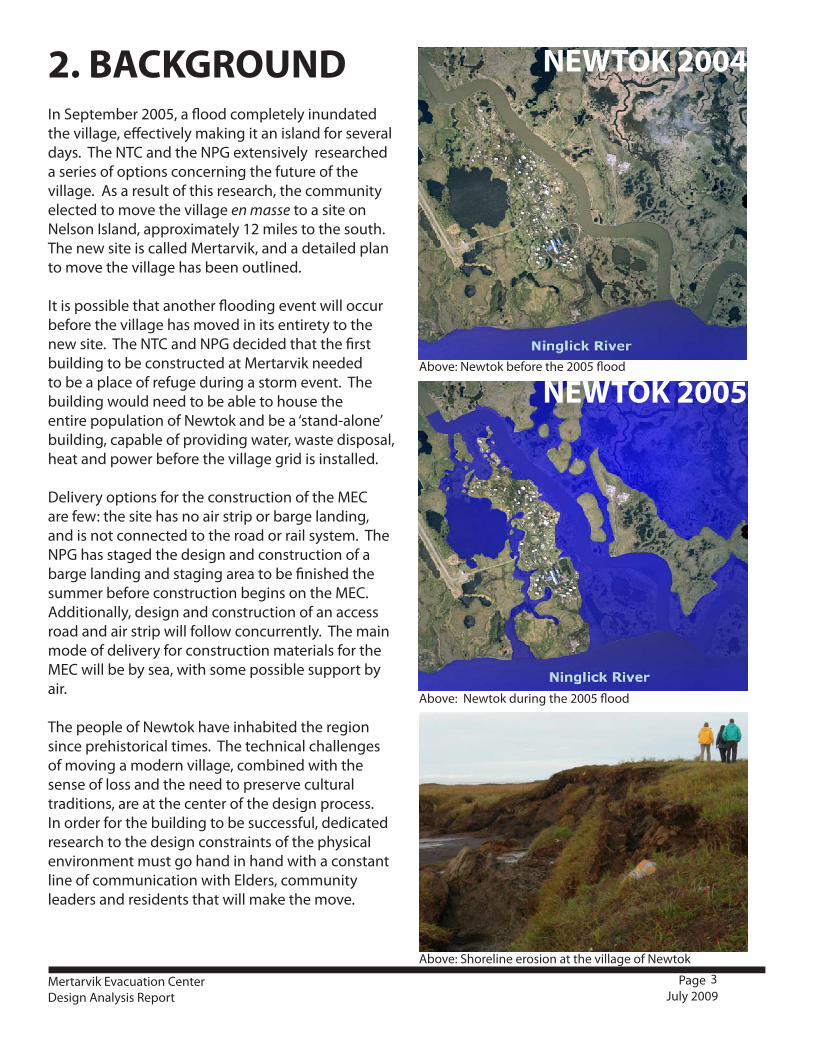
Above: Newtok during the 2005 flood
Above: Newtok before the 2005 flood
Above: Shoreline erosion at the village of Newtok
3Mertarvik Evacuation CenterDesign Analysis Report
Page July 2009
In September 2005, a flood completely inundated the village, effectively making it an island for several days. The NTC and the NPG extensively researched a series of options concerning the future of the village. As a result of this research, the community elected to move the village en masse to a site on Nelson Island, approximately 12 miles to the south. The new site is called Mertarvik, and a detailed plan to move the village has been outlined.
It is possible that another flooding event will occur before the village has moved in its entirety to the new site. The NTC and NPG decided that the first building to be constructed at Mertarvik needed to be a place of refuge during a storm event. The building would need to be able to house the entire population of Newtok and be a ‘stand-alone’ building, capable of providing water, waste disposal, heat and power before the village grid is installed.
Delivery options for the construction of the MEC are few: the site has no air strip or barge landing, and is not connected to the road or rail system. The NPG has staged the design and construction of a barge landing and staging area to be finished the summer before construction begins on the MEC. Additionally, design and construction of an access road and air strip will follow concurrently. The main mode of delivery for construction materials for the MEC will be by sea, with some possible support by air.
The people of Newtok have inhabited the region since prehistorical times. The technical challenges of moving a modern village, combined with the sense of loss and the need to preserve cultural traditions, are at the center of the design process. In order for the building to be successful, dedicated research to the design constraints of the physical environment must go hand in hand with a constant line of communication with Elders, community leaders and residents that will make the move.
2. BACKGROUND
NEWTOK 2005
NEWTOK 2004

Above: The school was designed to be disassembled
Above: The delivery options are by barge and air
Above: unused buildings should be cataloged for recycling
Above: Some houses will be moveable
4Mertarvik Evacuation CenterDesign Analysis Report
Page July 2009
The first step in designing the MEC consisted of a series of site visits to both the community of Newtok and the Mertarvik site. The goals of these site visits were to:
1. Establish a relationship with the community wherein residents could feel comfortable voicing wants, needs, and concerns regarding the move to Mertarvik and the MEC specifically,2. Survey the site conditions at both locations and design constraints that affect the building,3. Catalog the built form in the existing village
Built form in the village reacts with varying success to challenges typical to rural Alaska. Shipment of construction materials is costly; foundation design and heating efficiency have disproportionate importance; and funds to carry out construction, renovations, or even basic maintenance are scarce.
In order to maximize efficiency, the MEC must be seen as part of a larger plan to move the entire community. Some buildings, such as the school, have been designed with a possible move in mind. Some modern homes are in good enough condition to be moved whole. Other older buildings need to be analyzed and fully cataloged in order to assess the possibility of disassembly and harvesting of materials for reuse. These materials could possibly form part of the MEC, saving on costs and materials.
Just as importantly, the design team needed to analyze the site in different seasons, so as to understand the varying conditions of the old village, the new site, and the body of water in between, all of which influence the design of the MEC. The design team visited the village three times:
1. September 16-17 Initial site visit, meetings with community leaders, field trip to Mertarvik2. November 3-5 Design Charette3. March 9-10 Aborted due to inclement weather4. April 13-15 winter conditions survey, siting meeting with community.
3. PROCESS
Sally Russel-Cox Stanley Tom
George Elder Michael John
Jack Hebert Grant Kasharuk
Ty Keltner Aaron Cooke
5Mertarvik Evacuation CenterDesign Analysis Report
Page July 2009
4.1 OVERVIEW The CCHRC team recommended that a design charette be held in the community before the start of schematic design. The design charette is a tool that establishes a participatory design process in which the community and the design team work closely together to establish the design criteria for the building. This process has three main effects:1. It informs the design of the building based on not only the technical factors that are the specialization of the designers, but also on the unique needs and culture of the occupants.2. It creates a relationship in which open communication lines are established between occupant and designer3. It creates a sense of ownership within the community over the design of the building
The goal of the design charette was to get an understanding of the needs of the community for the evacuation center and to develop a program based on the synthesis of current best practices and feedback from the community. The CCHRC team conducted the charette over the period of three days: the 3rd-5th of November 2008. The schedule of activities is detailed below.
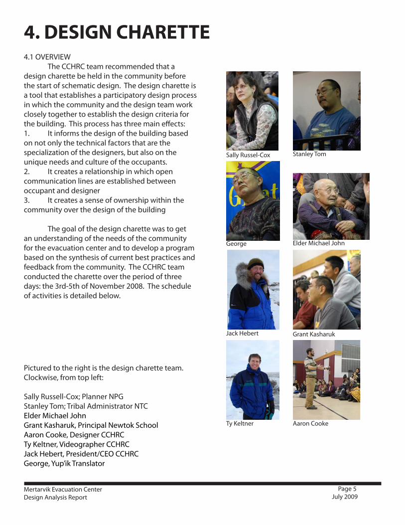
Pictured to the right is the design charette team. Clockwise, from top left:
Sally Russell-Cox; Planner NPGStanley Tom; Tribal Administrator NTCElder Michael JohnGrant Kasharuk, Principal Newtok SchoolAaron Cooke, Designer CCHRCTy Keltner, Videographer CCHRCJack Hebert, President/CEO CCHRCGeorge, Yup’ik Translator
4. DESIGN CHARETTE

6Mertarvik Evacuation CenterDesign Analysis Report
Page July 2009
Day1: The team arrived in the morning and met with tribal leadership to discuss the charette, the venue, and materials. They met with the school principal to arrange all A/V equipment. They then took a walking tour of the village, introducing themselves to residents and personally inviting them to the charette. That evening, they introduced the charette process. This is an important part of the overall charette, as people are less bashful if they are aware of the amount of feedback needed to make the process work. The design team showed a film of a design charette in the North Slope community of Anaktuvuk Pass where direct input from the community led to a better designed, affordable and culturally-appropriate home in the village. The meeting was attended by approximately a quarter of the village. It lasted about two hours.
Day2: During the day, the design team and a local guide went to examine the current state of erosion on the shore and look at the possibility of traveling to the new Mertarvik site. Baird Inlet and the Ninglick River were not completely frozen, precluding travel to the site. After surveying and documenting the erosion, the team went to inspect old semi-subterranean homes on the other side of the Newtok River. The guide described some of the characteristics of these homes: how they worked culturally and physically, and talked about local residents who had been born in such dwellings. In the evening, the main charette event began around 8:30PM. About 1/3 of the village was in attendance. A local translator ensured that all items discussed in the charette could be understood and added to by Elders in attendance. The charette discussion began with the site at Mertarvik. The people voiced their concern over the new site being so far up from the shoreline, and the factor of safety used to site the new village. It was decided that in March, the design team, members of the Newtok Planning Group, local leaders and Elders would travel to Mertarvik and ensure that the correct siting of the building has been decided. The second item on the agenda was to discuss the evacuation plan and programmatic needs of the evacuation center. The community and design team described the functions that the center needed to perform in an emergency situation, and what spaces should be allocated to those functions. The third item on the agenda was to discuss the building’s second life: that of the community center for the new village. To save on costs, it was important to be able to draw a line between spaces used in the evacuation center and their second use when the building has graduated into a community center. This thought process will lead to a more suitable and sustainable building with a longer lifespan. At the end of the charette, the team stayed and spoke to Elders for an hour about the history of the area, the subsistence sources nearby of importance, and the local knowledge of Mertarvik weather patterns and topography.
Day3: The program for the building came directly from the synthesis of the design team’s understanding of emergency shelter design and the specific needs of the community in this unique situation. On the morning of the third day the CCHRC team met with representatives of the Newtok Planning Group, the Department of Transportation, and the Newtok Tribal Administration and discussed the results of the charette, forming an architectural program with which to start schematic design.
4.2 DESIGN CHARETTE:PROCESS
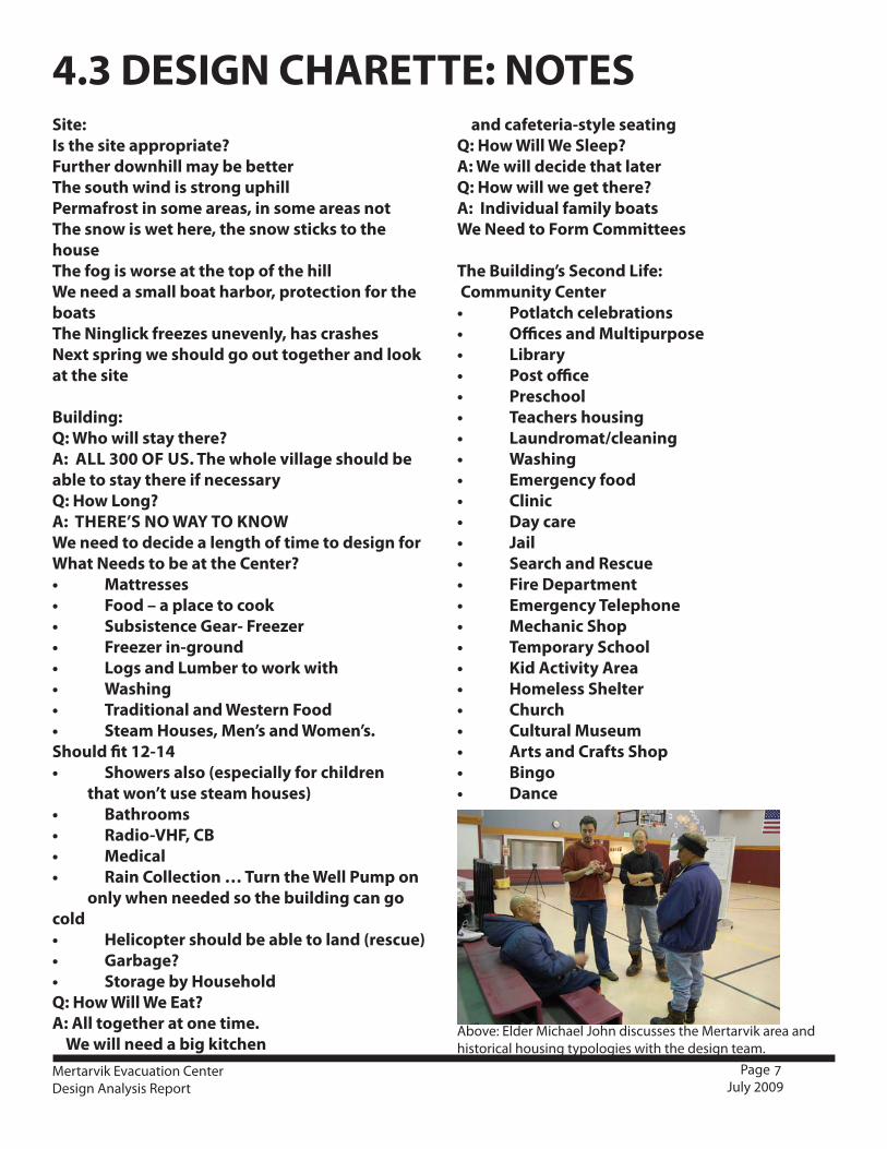
Above: Elder Michael John discusses the Mertarvik area and historical housing typologies with the design team.
7Mertarvik Evacuation CenterDesign Analysis Report
Page July 2009
Site:Is the site appropriate?Further downhill may be betterThe south wind is strong uphillPermafrost in some areas, in some areas notThe snow is wet here, the snow sticks to the houseThe fog is worse at the top of the hillWe need a small boat harbor, protection for the boatsThe Ninglick freezes unevenly, has crashesNext spring we should go out together and look at the site
Building:Q: Who will stay there?A: ALL 300 OF US. The whole village should be able to stay there if necessaryQ: How Long?A: THERE’S NO WAY TO KNOWWe need to decide a length of time to design forWhat Needs to be at the Center?• Mattresses• Food–aplacetocook• SubsistenceGear-Freezer• Freezerin-ground• LogsandLumbertoworkwith• Washing• TraditionalandWesternFood• SteamHouses,Men’sandWomen’s.Should fit 12-14• Showersalso(especiallyforchildren that won’t use steam houses)• Bathrooms• Radio-VHF,CB• Medical• RainCollection…TurntheWellPumpon only when needed so the building can go cold• Helicoptershouldbeabletoland(rescue)• Garbage?• StoragebyHouseholdQ: How Will We Eat?A: All together at one time. We will need a big kitchen
and cafeteria-style seatingQ: How Will We Sleep?A: We will decide that laterQ: How will we get there?A: Individual family boatsWe Need to Form Committees
The Building’s Second Life: Community Center• Potlatchcelebrations• OfficesandMultipurpose• Library• Postoffice• Preschool• Teachershousing• Laundromat/cleaning• Washing• Emergencyfood• Clinic• Daycare• Jail• SearchandRescue• FireDepartment• EmergencyTelephone• MechanicShop• TemporarySchool• KidActivityArea• HomelessShelter• Church• CulturalMuseum• ArtsandCraftsShop• Bingo• Dance
4.3 DESIGN CHARETTE: NOTES
8Mertarvik Evacuation CenterDesign Analysis Report
Page July 2009
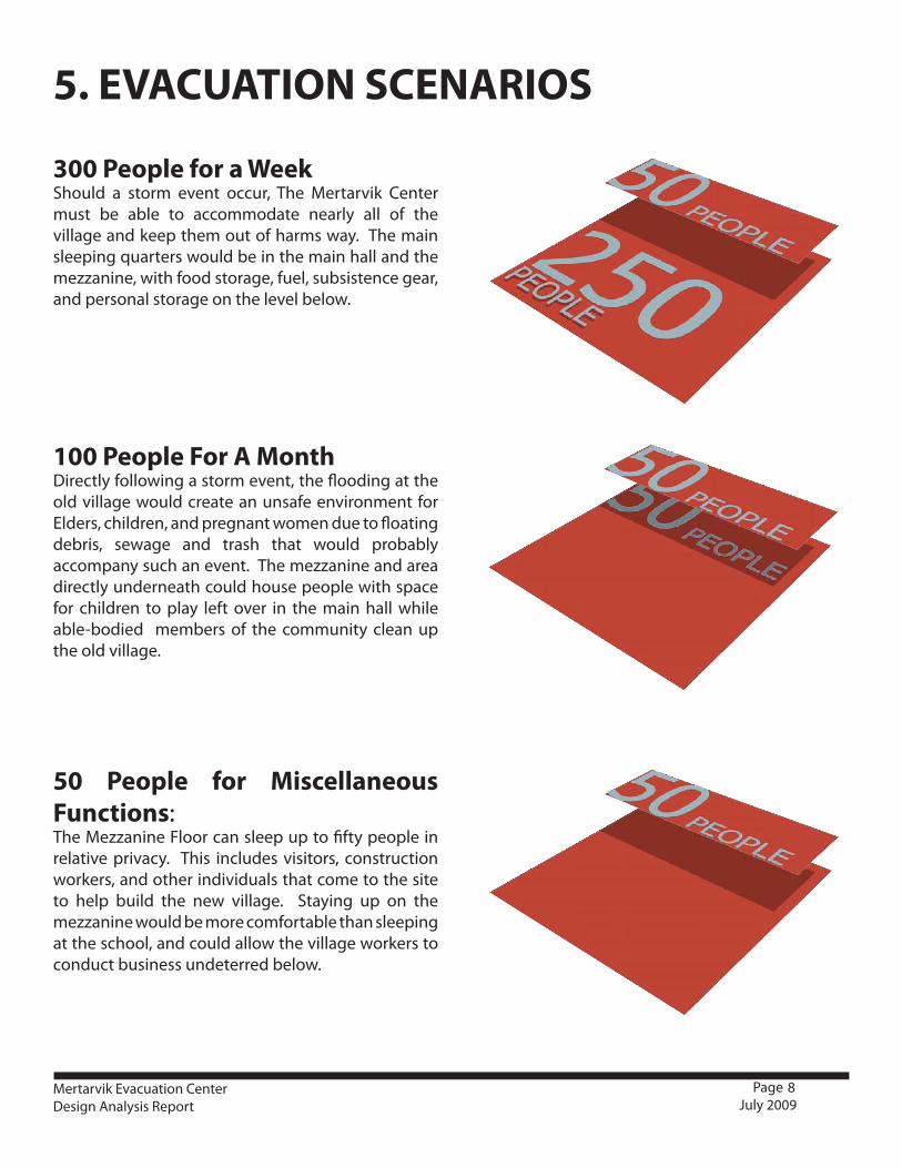
300 People for a WeekShould a storm event occur, The Mertarvik Center must be able to accommodate nearly all of the village and keep them out of harms way. The main sleeping quarters would be in the main hall and the mezzanine, with food storage, fuel, subsistence gear, and personal storage on the level below.
100 People For A MonthDirectly following a storm event, the flooding at the old village would create an unsafe environment for Elders, children, and pregnant women due to floating debris, sewage and trash that would probably accompany such an event. The mezzanine and area directly underneath could house people with space for children to play left over in the main hall while able-bodied members of the community clean up the old village.
50 People for Miscellaneous Functions:The Mezzanine Floor can sleep up to fifty people in relative privacy. This includes visitors, construction workers, and other individuals that come to the site to help build the new village. Staying up on the mezzanine would be more comfortable than sleeping at the school, and could allow the village workers to conduct business undeterred below.
5. EVACUATION SCENARIOS

Above and Below: Thaw-bulb action
Above: piles create more surface area and heat loss
Traditional dwellings used ingenious methods to retain heat
Piles can create subsidence issues
9Mertarvik Evacuation CenterDesign Analysis Report
Page July 2009
6.1 Built Form:Foundation design is problematic in the existing village of Newtok. The soil consists of ice-rich permafrost with a high water table; buildings built on grade tend to leak heat and create a thaw bulb that melts the permafrost directly under the building, causing differential settlement and leading to eventual structural failure. Buildings that melt the permafrost around their foundations tend to sink down into the ground. As they have not been protected or flashed for this event, they also tend to take in water and experience wall and floor rot, creating poor indoor air quality and mold.
More recently, pile foundations have placed homes and public buildings up in the air so as to mitigate thaw bulb action and also inhibit snow drift. If these were the only issues in consideration, this would be the best strategy. However, piles still jack with seasonal frost heave, and they expose more surface area of the building to the elements, which makes it much more difficult to heat effectively. Heating load is a major concern in the village: the barge that delivers fuel can only come until Baird Inlet freezes over sometime in October, and often cannot deliver fuel again until May. The village routinely runs out of fuel before Breakup, and must buy from the school’s reserves or even transport drums individually by snowmachine.
In historical times, villagers traditionally built their dwellings in the ground to use the earth to temper the cold. There are still residents alive in Newtok that were born in these dwellings, and during the charette they described how much easier it was to keep them warm than the modern houses.
Subsidence is also a problem. Heat transfer from piles to unstable soils can cause the ground to subside from under the building. The implementation of gravel also contributes to subsidence: the darker gravel heats at a different rate than vegetation-covered soil and the ground can sink away from the foundation.
6.SITE/CIVIL/FOUNDATION
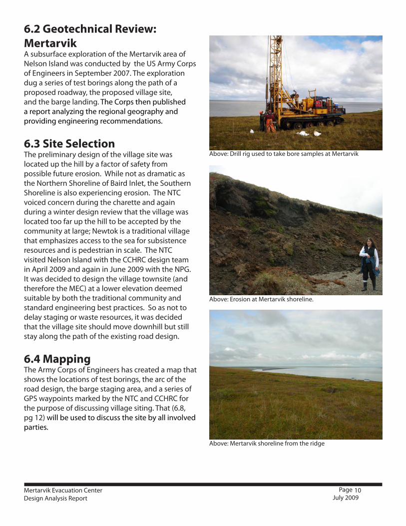
Above: Drill rig used to take bore samples at Mertarvik
Above: Erosion at Mertarvik shoreline.
Above: Mertarvik shoreline from the ridge
10Mertarvik Evacuation CenterDesign Analysis Report
Page July 2009
6.2 Geotechnical Review: MertarvikA subsurface exploration of the Mertarvik area of Nelson Island was conducted by the US Army Corps of Engineers in September 2007. The exploration dug a series of test borings along the path of a proposed roadway, the proposed village site, and the barge landing. The Corps then published a report analyzing the regional geography and providing engineering recommendations.
6.3 Site Selection The preliminary design of the village site was located up the hill by a factor of safety from possible future erosion. While not as dramatic as the Northern Shoreline of Baird Inlet, the Southern Shoreline is also experiencing erosion. The NTC voiced concern during the charette and again during a winter design review that the village was located too far up the hill to be accepted by the community at large; Newtok is a traditional village that emphasizes access to the sea for subsistence resources and is pedestrian in scale. The NTC visited Nelson Island with the CCHRC design team in April 2009 and again in June 2009 with the NPG. It was decided to design the village townsite (and therefore the MEC) at a lower elevation deemed suitable by both the traditional community and standard engineering best practices. So as not to delay staging or waste resources, it was decided that the village site should move downhill but still stay along the path of the existing road design.
6.4 MappingThe Army Corps of Engineers has created a map that shows the locations of test borings, the arc of the road design, the barge staging area, and a series of GPS waypoints marked by the NTC and CCHRC for the purpose of discussing village siting. That (6.8, pg 12) will be used to discuss the site by all involved parties.
11Mertarvik Evacuation CenterDesign Analysis Report
Page July 2009
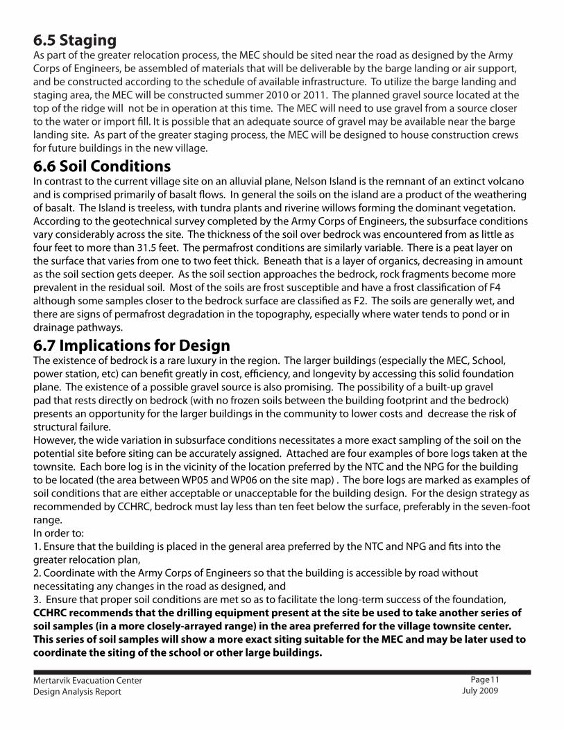
6.5 StagingAs part of the greater relocation process, the MEC should be sited near the road as designed by the Army Corps of Engineers, be assembled of materials that will be deliverable by the barge landing or air support, and be constructed according to the schedule of available infrastructure. To utilize the barge landing and staging area, the MEC will be constructed summer 2010 or 2011. The planned gravel source located at the top of the ridge will not be in operation at this time. The MEC will need to use gravel from a source closer to the water or import fill. It is possible that an adequate source of gravel may be available near the barge landing site. As part of the greater staging process, the MEC will be designed to house construction crews for future buildings in the new village.
6.6 Soil ConditionsIn contrast to the current village site on an alluvial plane, Nelson Island is the remnant of an extinct volcano and is comprised primarily of basalt flows. In general the soils on the island are a product of the weathering of basalt. The Island is treeless, with tundra plants and riverine willows forming the dominant vegetation.According to the geotechnical survey completed by the Army Corps of Engineers, the subsurface conditions vary considerably across the site. The thickness of the soil over bedrock was encountered from as little as four feet to more than 31.5 feet. The permafrost conditions are similarly variable. There is a peat layer on the surface that varies from one to two feet thick. Beneath that is a layer of organics, decreasing in amount as the soil section gets deeper. As the soil section approaches the bedrock, rock fragments become more prevalent in the residual soil. Most of the soils are frost susceptible and have a frost classification of F4 although some samples closer to the bedrock surface are classified as F2. The soils are generally wet, and there are signs of permafrost degradation in the topography, especially where water tends to pond or in drainage pathways.
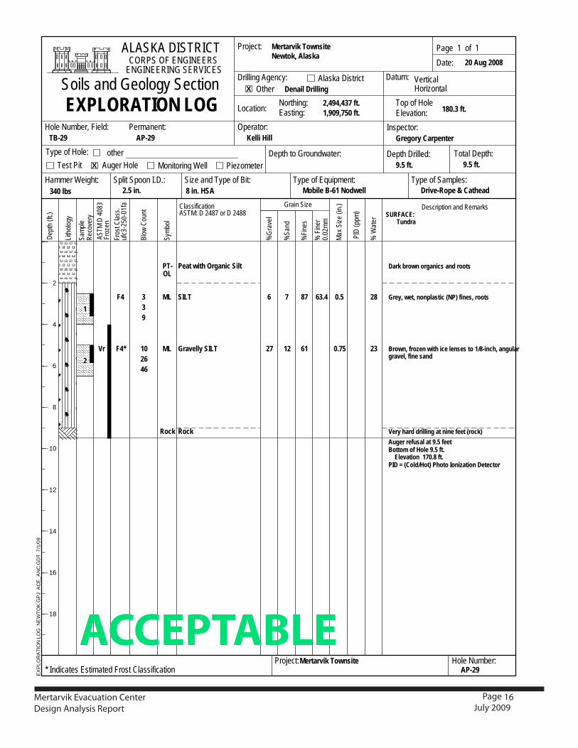
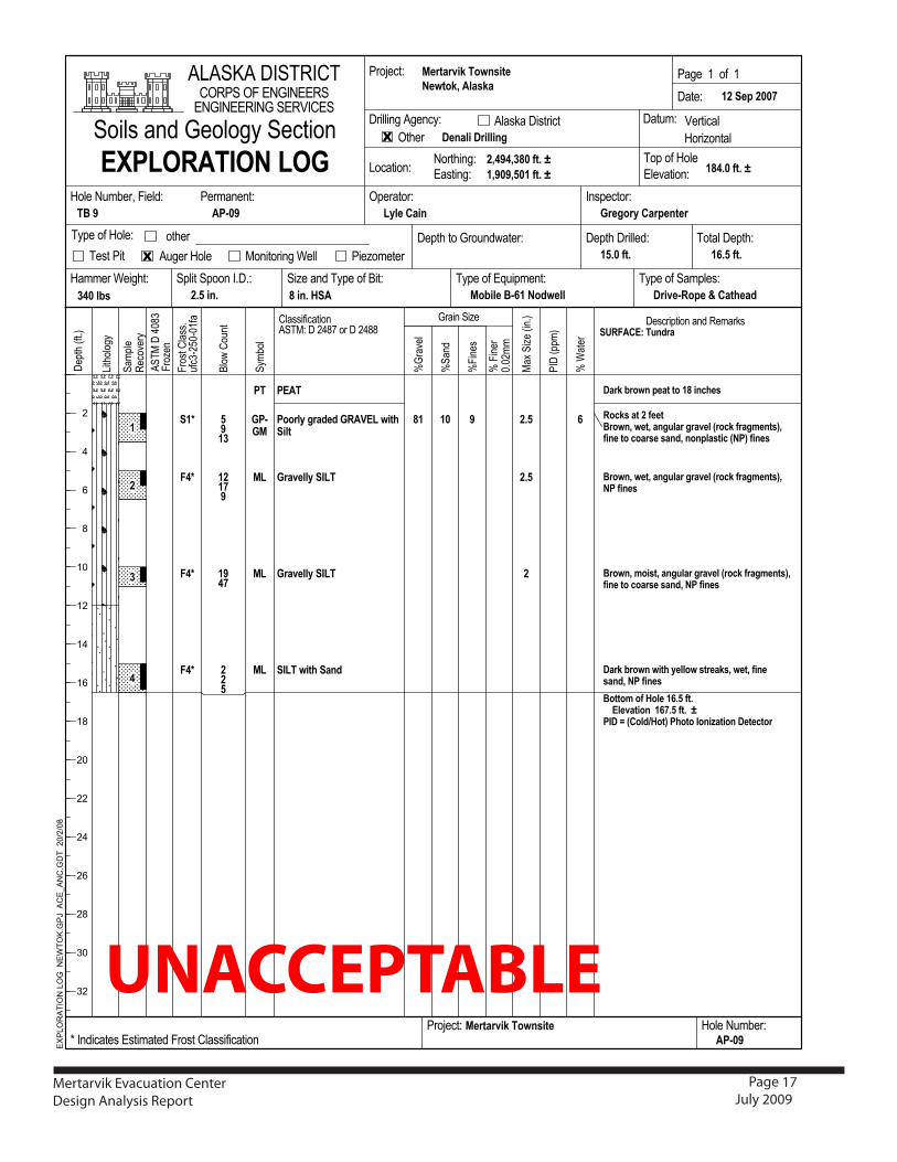
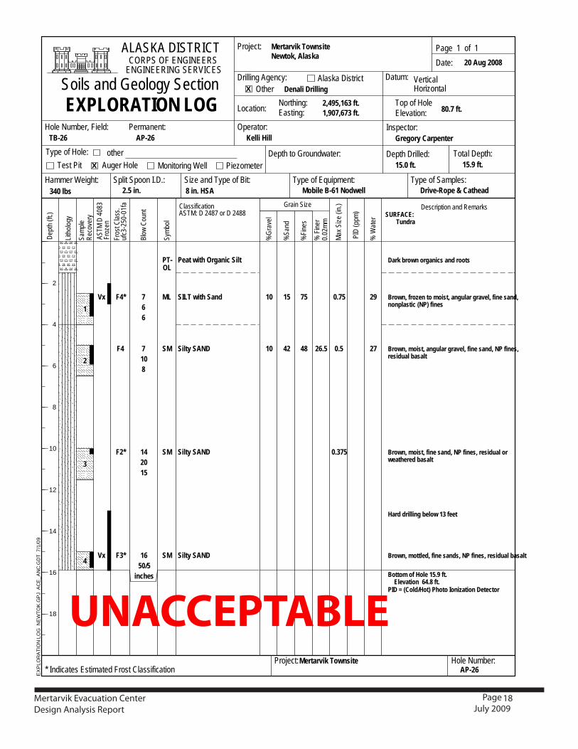
6.7 Implications for DesignThe existence of bedrock is a rare luxury in the region. The larger buildings (especially the MEC, School, power station, etc) can benefit greatly in cost, efficiency, and longevity by accessing this solid foundation plane. The existence of a possible gravel source is also promising. The possibility of a built-up gravel pad that rests directly on bedrock (with no frozen soils between the building footprint and the bedrock) presents an opportunity for the larger buildings in the community to lower costs and decrease the risk of structural failure. However, the wide variation in subsurface conditions necessitates a more exact sampling of the soil on the potential site before siting can be accurately assigned. Attached are four examples of bore logs taken at the townsite. Each bore log is in the vicinity of the location preferred by the NTC and the NPG for the building to be located (the area between WP05 and WP06 on the site map) . The bore logs are marked as examples of soil conditions that are either acceptable or unacceptable for the building design. For the design strategy as recommended by CCHRC, bedrock must lay less than ten feet below the surface, preferably in the seven-foot range.In order to:1. Ensure that the building is placed in the general area preferred by the NTC and NPG and fits into the greater relocation plan,2. Coordinate with the Army Corps of Engineers so that the building is accessible by road without necessitating any changes in the road as designed, and3. Ensure that proper soil conditions are met so as to facilitate the long-term success of the foundation,CCHRC recommends that the drilling equipment present at the site be used to take another series of soil samples (in a more closely-arrayed range) in the area preferred for the village townsite center. This series of soil samples will show a more exact siting suitable for the MEC and may be later used to coordinate the siting of the school or other large buildings.
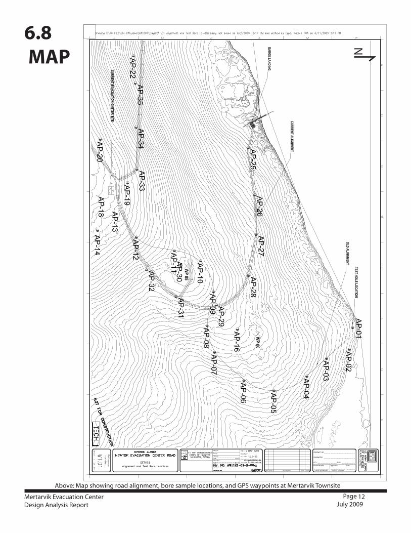
Above: Map showing road alignment, bore sample locations, and GPS waypoints at Mertarvik Townsite
12
N
Mertarvik Evacuation CenterDesign Analysis Report
Page July 2009
6.8 MAP

Above: Close-up of Mertarvik townsite map
13
200ft
N
AP-26
Mertarvik Evacuation CenterDesign Analysis Report
Page July 2009
The general area for the MEC site is the area between WP05 and WP06 on the Mertarvik Map. This area is a North and North-East facing slope of around 7-10% between two ‘benches’ of land that are of more gradual slope to near level. The soil samples nearest the initial site indicated by the NTC and NPG are bore logs AP29 and AP09. A later meeting indicated a preference for the region surrounding AP-28 or possibly AP-26. These bore logs are provided below to show not only the variation in soil in the area, but also the appropriateness for the foundation as designed. Of the four examples, bore log AP28 is the most suitable, while AP29 is also suitable: bedrock was encountered at depths of four feet in AP-28 and at nine feet in AP-29. AP09 and AP26 are unacceptable sites due to the depth of rock and the amount of frost- susceptible land that would have to be cleared away to get to it.
SITE PLAN FACTORS1. The building will have a footprint of 7040SF (88 by 80 feet), with a 750SF foot outdoor deck and a two arctic entries totalling 355SF.2. Seven parking spaces for passenger vehicles or ATVs on the south side, and garage access for full-size vehicles and turn-around area on the north side3. Grade change for access to lower floor on the north side of the building with proper drainage around the structure4. Proper solar orientation to maximize daylighting and minimize heat loss5. Proper site orientation to minimize snow drift6. Proximity and access to original road design
8.1 SITE PREPARATION •Takeadditional5-10borings(iffeasible)intheareabetweenAP-28andAP-29togetamoreexactidea of subsoil conditions beneath the footprint.•ClearthesiteofallorganicandFSmaterialdowntothebedrock.Overexcavateandsetasidesuitablematerial to be used later. •Levelirregularitiesinthebasaltwitha6-8inchlevelingcourseofgravel.Fillmaycomefromcrushedmaterial near by. Alternatively, it may be imported, but this will add cost.•Constructabuilt-up-gravelpad,ensuringthatnofrostsusceptible(FS)organicmaterialisleft
7. SITE PLAN
8. FOUNDATION RECOMMENDATIONS

14Mertarvik Evacuation CenterDesign Analysis Report
Page July 2009
between the basalt base and the gravel pad. •Compactthepadto95percentofthemaximumdrydensity.Thereshouldbeaminimum6-8inchesof NFS fill beneath the footing.
8.2 FOUNDATION DESIGN STRATEGY
This foundation design is intended to minimize material and provide structural longevity. It utilizes no concrete. The foundation transfers loads directly to bedrock allowing relatively high design soil bearing capacity values. Earth is bermed against the lower level of the building to regulate temperature and reduce surface area exposed to wind and air. This strategy creates a more stable long-term foundation while simultaneously lowering the overall surface-to-volume ratio of the building and reducing the heating load. The exterior side of the foundation will be sprayed with up to 9 inches of soy-based urethane foam insulation and finished with an elastomeric coating, then bermed with fill material up to 8’.•Underthebasementfloorwillbeawater/vaporbarrierplacedovercompactedfill.Floorjoistswillbeinstalled and 9” of soy-urethane insulation will be sprayed between the joists over the water barrier. This will lock in the floor joists, which will be blocked up 4” from the top of the compacted soil. The soy will be sprayed out laterally from the footing to prevent frost and water from spreading under the foundation, and the floor assembly will be detailed to eliminate any thermal bridging.
8.3 ALL WEATHER WOOD AND METAL WALL FOUNDATION
•Theperimeterofthebuildingwillbesupportedoncolumnswithtreatedtimberfootings.Metalstud framing between the columns will support the earth loads from the berm. This ‘infill’ wall will be built on a 4x12 treated timber footing. Metal studs will be spray foamed from the out side of the wall and coated with a sprayed on water proofing layer.•TheInteriormainhallfloorwillbesupportedbyacontinuousponywallon4x12timberfootings.•Footingsexposedtofreezingtemperaturesalongtheexteriorwallofthestructure-bottomedatleast 18 inches below exterior grade •Isolatedinteriorfootingsnotexposedtocoldtemperatures-bottomedatleast12inchesbelowthe floor. 8.4 FOOTING DESIGN
Design recommendations for installing the footings described above include: •Useabearingpressureof3,000poundspersquarefoot(psf )fordeadplussustainedliveloads.•Use4,000psffortotaldesignloadsincludingwindandseismic.•Classifiedfillshallbeproperlycompacted,suchthattotalsettlementswillbelessthan1inch.Most of the settlement will occur as the loads are applied; post-construction differential settlements are expected to be less than one-half inch. Lateral loads can be resisted by friction on the base of the footings and by passive pressures against the face of the footings. Later pressure for full height retaining walls will be resisted by the basement floor system.•Itisrecommendedthatanexperiencedengineerbeusedtoinspectandtesttheoverexcavationof organics and loose soil, placement and compaction of new fill, footing excavations prior to construction of the footings. Inspection will permit the detection of unanticipated conditions and allow verification that the work is done.

15
22 1
1
0.5
PT-OL
ML
Rock
Rock
257
524843
953
9
Peat with Organic Silt
SILT
Rock
Rock
69 26F4*
Dark brown organics and roots
Brown, wet, angular gravel, fine sand, nonplasticfines, roots
Hard drilling at 4.5 feetWeathered rock and silt
Weathered rock
Auger refusal at 12.5 feetBottom of Hole 12.5 ft. Elevation 131.2 ft.PID = (Cold/Hot) Photo Ionization Detector
Symb
ol
EXPLORATION LOG
Description and Remarks
Dept
h (ft
.)
%Gr
avel
Grain Size
Blow
Cou
nt SURFACE: Tundra
ASTM
D 4
083
Froz
en
Samp
leRe
cove
ry
Litho
logy
%Fin
es
%Sa
nd
% W
ater
PID
(ppm
)
Max S
ize (i
n.)Classification
ASTM: D 2487 or D 2488
% F
iner
0.02
mm
Fros
t Clas
s.uf
c3-2
50-0
1fa
CORPS OF ENGINEERSENGINEERING SERVICES
ALASKA DISTRICT
Hole Number, Field:
Hole Number:
Northing:Easting:Location:
AP-28
Drive-Rope & Cathead
Denail Drilling
2.5 in. Mobile B-61 Nodwell
Mertarvik TownsiteNewtok, Alaska
Piezometer
Project:
Drilling Agency: Alaska District
other
Type of Samples:
Other Horizontal
Type of Hole:
2
4
6
8
10
12
14
16
18
Page 1 of 1
TB-28
AP-28
2,495,042 ft.1,909,195 ft.
Split Spoon I.D.:
Mertarvik Townsite
Operator:
X
Auger Hole
Permanent:
X
Vertical
Inspector:
Total Depth:12.5 ft.Monitoring Well
340 lbs
Soils and Geology Section 20 Aug 2008Date:
Test Pit
Project:
Kelli Hill
8 in. HSAHammer Weight: Size and Type of Bit:
Depth to Groundwater:
Type of Equipment:
* Indicates Estimated Frost Classification
Top of HoleElevation:
Datum:
143.7 ft.
Gregory Carpenter
Depth Drilled:12.5 ft.
EX
PLO
RA
TIO
N L
OG
NE
WTO
K.G
PJ
AC
E_A
NC
.GD
T 7
/1/0
9
1
2
3
ACCEPTABLE
9. BORE LOGS
Mertarvik Evacuation CenterDesign Analysis Report
Page July 2009
16
7
12
0.5
0.75
PT-OL
ML
ML
Rock
339
102646
6
27
Peat with Organic Silt
SILT
Gravelly SILT
Rock
87
61
28
23
63.4F4
F4*Vr
Dark brown organics and roots
Grey, wet, nonplastic (NP) fines, roots
Brown, frozen with ice lenses to 1/8-inch, angulargravel, fine sand
Very hard drilling at nine feet (rock)Auger refusal at 9.5 feetBottom of Hole 9.5 ft. Elevation 170.8 ft.PID = (Cold/Hot) Photo Ionization Detector
Symb
ol
EXPLORATION LOG
Description and Remarks
Dept
h (ft
.)
%Gr
avel
Grain Size
Blow
Cou
nt SURFACE: Tundra
ASTM
D 4
083
Froz
en
Samp
leRe
cove
ry
Litho
logy
%Fin
es
%Sa
nd
% W
ater
PID
(ppm
)
Max S
ize (i
n.)Classification
ASTM: D 2487 or D 2488
% F
iner
0.02
mm
Fros
t Clas
s.uf
c3-2
50-0
1fa
CORPS OF ENGINEERSENGINEERING SERVICES
ALASKA DISTRICT
Hole Number, Field:
Hole Number:
Northing:Easting:Location:
AP-29
Drive-Rope & Cathead
Denail Drilling
2.5 in. Mobile B-61 Nodwell
Mertarvik TownsiteNewtok, Alaska
Piezometer
Project:
Drilling Agency: Alaska District
other
Type of Samples:
Other Horizontal
Type of Hole:
2
4
6
8
10
12
14
16
18
Page 1 of 1
TB-29
AP-29
2,494,437 ft.1,909,750 ft.
Split Spoon I.D.:
Mertarvik Townsite
Operator:
X
Auger Hole
Permanent:
X
Vertical
Inspector:
Total Depth:9.5 ft.Monitoring Well
340 lbs
Soils and Geology Section 20 Aug 2008Date:
Test Pit
Project:
Kelli Hill
8 in. HSAHammer Weight: Size and Type of Bit:
Depth to Groundwater:
Type of Equipment:
* Indicates Estimated Frost Classification
Top of HoleElevation:
Datum:
180.3 ft.
Gregory Carpenter
Depth Drilled:9.5 ft.
EX
PLO
RA
TIO
N L
OG
NE
WTO
K.G
PJ
AC
E_A
NC
.GD
T 7
/1/0
9
1
2
ACCEPTABLEMertarvik Evacuation CenterDesign Analysis Report
Page July 2009
17
!"#$%&
'&()*&+,
-!./
ÿ0ÿ1234
5+)6&7
!"#$%&'(ÿ)*+,-.
8%)9ÿ:);7<
!,#=)%
:%">>?@?("<?)7-!./Aÿ0ÿB13Cÿ)+ÿ0ÿB133
!"#$%&'()%*ÿ$%+ÿÿ*!,(%-.+#/ÿÿ'0!1'*0.+2(ÿÿ3453546
DE0ÿF$$#G
HÿI"<&+
J+"?7ÿ!?6&
K?<L)%)M,
H5?7&>
0&$<LÿF@<NG
0&>(+?$<?)7ÿ"7Oÿ'&#"+P>
'/012#%)324ÿ125
H!"7O
HJ+"*&%
61
#789:ÿ.;ÿ<ÿ=>>;
?.-9ÿ@-7A+ÿB>.;ÿ;7ÿCDÿE+8F>:
GDC
<<H
CIJK
C<CKI
HICL
61
M-7A+NÿO7E:;Nÿ.+P*Q.-ÿP-.R>QÿS-789ÿ=-.PO>+;:TN=E+>ÿ;7ÿ87.-:>ÿ:.+,Nÿ40ÿ=E+>:
61
50U56
0)
<
<VH
<VHCW I
!31)ÿAE;Fÿ!.+,
5-.R>QQXÿ!31)
5-.R>QQXÿ!31)
077-QXÿP-.,>,ÿ5#%Y'1ÿAE;F!EQ;
0'%)
$JZ
$JZ
$JZ
!CZ M-7A+NÿA>;Nÿ.+P*Q.-ÿP-.R>QÿS-789ÿ=-.PO>+;:TN=E+>ÿ;7ÿ87.-:>ÿ:.+,Nÿ+7+BQ.:;E8ÿS40Tÿ=E+>:
M-7A+NÿA>;Nÿ.+P*Q.-ÿP-.R>QÿS-789ÿ=-.PO>+;:TN40ÿ=E+>:
M7;;7Oÿ7=ÿ[7Q>ÿCGVHÿ=;V'Q>R.;E7+ÿÿCGKVHÿ=;Vÿÿ\
03?ÿ]ÿS&7Q,^[7;Tÿ0F7;7ÿ37+E_.;E7+ÿ?>;>8;7-
?.-9ÿ@-7A+ÿAE;FÿX>QQ7Aÿ:;->.9:NÿA>;Nÿ=E+>:.+,Nÿ40ÿ=E+>:
<NJIJNLDWÿ=;Vÿ\CNIWINHWCÿ=;Vÿ\ CDJVWÿ=;Vÿ\
-;M&+ÿQ)%&
!
R$&+"<)+A
!$%?<ÿ!$))7ÿEN0NA!
%0UWI
CHVWÿ=;V
5->P7-Xÿ&.-B>+;>-)MÿI
D"M&ÿÿSÿÿ)@ÿÿS
/"Tÿ!
?6&ÿF?7NG
6>-;.-RE9ÿ)7A+:E;>UÿE7O?("<&>ÿV><?#"<&Oÿ5+)><ÿ:%">>?@?("<?)7
0&$<Lÿ0+?%%&OA
.,$&ÿ)@ÿVW;?$#&7<A
0&$<Lÿ<)ÿJ+);7O9"<&+A
!?6&ÿ"7Oÿ.,$&ÿ)@ÿ8?<AQ"##&+ÿI&?ML<ADÿE+Vÿ[!%
1XQ>ÿ&.E+
D+)X&(<A
D&+#"7&7<A
.&><ÿD?<
.)$ÿ)@ÿQ)%&V%&*"<?)7A
0"<&A C<ÿ!>Bÿ<WWK
!)?%>ÿ"7OÿJ&)%)M,ÿ!&(<?)7 0"<;#A
LJWÿQ@:
/)7?<)+?7MÿI&%%
K)("<?)7A
6>-;.-RE9ÿ)7A+:E;>4>A;79Nÿ%Q.:9.
67@EQ>ÿMUGCÿ47,A>QQ<VHÿE+V
Q)+?6)7<"%
CGVHÿ=;V
?>+.QEÿ?-EQQE+P
?-ER>U#7B>ÿ`ÿ&.;F>.,
%0UWI
D+)X&(<A
Y)+<L?7MAV"><?7MA
Q)%&ÿY;#=&+A
Q)%&ÿY;#=&+Zÿ5?&%OA
-K-![-ÿ0E!.'E:.:R'D!ÿR5ÿVYJEYVV'!VYJEYVV'EYJÿ!V'\E:V!
5+)><ÿ:%">>N
;@(4]B^2]2S@"
Hÿ5?7&+
2N2B##
.)<"%ÿ0&$<LA
\&+<?("%
.,$&ÿ)@ÿQ)%&A
E7>$&(<)+A
D?&6)#&<&+
3
7
8
6
94
93
97
98
96
34
33
37
38
36
:4
:3
.,$&ÿ)@ÿ!"#$%&>A
R<L&+
)<L&+
-%">P"ÿ0?><+?(<0+?%%?7Mÿ-M&7(,A
J
L
C
<
UNACCEPTABLEMertarvik Evacuation CenterDesign Analysis Report
Page July 2009
18
15
42
0.75
0.5
0.375
PT-OL
ML
SM
SM
SM
766
7108
142015
1650/5
inches
10
10
Peat with Organic Silt
SILT with Sand
Silty SAND
Silty SAND
Silty SAND
75
48
29
2726.5
F4*
F4
F2*
F3*
Vx
Vx
Dark brown organics and roots
Brown, frozen to moist, angular gravel, fine sand,nonplastic (NP) fines
Brown, moist, angular gravel, fine sand, NP fines,residual basalt
Brown, moist, fine sand, NP fines, residual orweathered basalt
Hard drilling below 13 feet
Brown, mottled, fine sands, NP fines, residual basalt
Bottom of Hole 15.9 ft. Elevation 64.8 ft.PID = (Cold/Hot) Photo Ionization Detector
Symb
ol
EXPLORATION LOG
Description and Remarks
Dept
h (ft
.)
%Gr
avel
Grain Size
Blow
Cou
nt SURFACE: Tundra
ASTM
D 4
083
Froz
en
Samp
leRe
cove
ry
Litho
logy
%Fin
es
%Sa
nd
% W
ater
PID
(ppm
)
Max S
ize (i
n.)Classification
ASTM: D 2487 or D 2488
% F
iner
0.02
mm
Fros
t Clas
s.uf
c3-2
50-0
1fa
CORPS OF ENGINEERSENGINEERING SERVICES
ALASKA DISTRICT
Hole Number, Field:
Hole Number:
Northing:Easting:Location:
AP-26
Drive-Rope & Cathead
Denali Drilling
2.5 in. Mobile B-61 Nodwell
Mertarvik TownsiteNewtok, Alaska
Piezometer
Project:
Drilling Agency: Alaska District
other
Type of Samples:
Other Horizontal
Type of Hole:
2
4
6
8
10
12
14
16
18
Page 1 of 1
TB-26
AP-26
2,495,163 ft.1,907,673 ft.
Split Spoon I.D.:
Mertarvik Townsite
Operator:
X
Auger Hole
Permanent:
X
Vertical
Inspector:
Total Depth:15.9 ft.Monitoring Well
340 lbs
Soils and Geology Section 20 Aug 2008Date:
Test Pit
Project:
Kelli Hill
8 in. HSAHammer Weight: Size and Type of Bit:
Depth to Groundwater:
Type of Equipment:
* Indicates Estimated Frost Classification
Top of HoleElevation:
Datum:
80.7 ft.
Gregory Carpenter
Depth Drilled:15.0 ft.
EX
PLO
RA
TIO
N L
OG
NE
WTO
K.G
PJ
AC
E_A
NC
.GD
T 7
/1/0
9
1
2
3
4
UNACCEPTABLE
Mertarvik Evacuation CenterDesign Analysis Report
Page July 2009
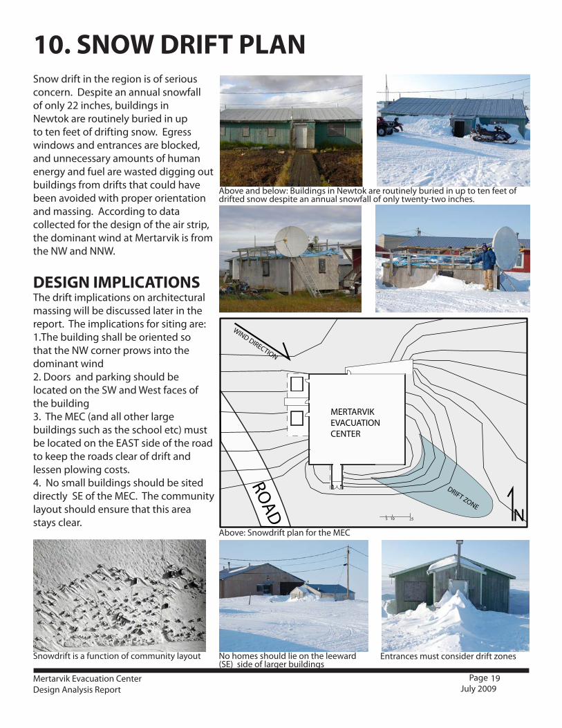
Above and below: Buildings in Newtok are routinely buried in up to ten feet of drifted snow despite an annual snowfall of only twenty-two inches.
Above: Snowdrift plan for the MEC
Snowdrift is a function of community layout No homes should lie on the leeward (SE) side of larger buildings
Entrances must consider drift zones
19
5 2510
ROAD
WIND DIRECTION
DRIFT ZONE
MERTARVIKEVACUATIONCENTER
N
Mertarvik Evacuation CenterDesign Analysis Report
Page July 2009
10. SNOW DRIFT PLANSnow drift in the region is of serious concern. Despite an annual snowfall of only 22 inches, buildings in Newtok are routinely buried in up to ten feet of drifting snow. Egress windows and entrances are blocked, and unnecessary amounts of human energy and fuel are wasted digging out buildings from drifts that could have been avoided with proper orientation and massing. According to data collected for the design of the air strip, the dominant wind at Mertarvik is from the NW and NNW.
DESIGN IMPLICATIONSThe drift implications on architectural massing will be discussed later in the report. The implications for siting are:1.The building shall be oriented so that the NW corner prows into the dominant wind2. Doors and parking should be located on the SW and West faces of the building3. The MEC (and all other large buildings such as the school etc) must be located on the EAST side of the road to keep the roads clear of drift and lessen plowing costs.4. No small buildings should be sited directly SE of the MEC. The community layout should ensure that this area stays clear.

20
DANCE SPACE, BINGO, POTLATCHES
SLEEPING SPACE5160SF (NET)*
SECURE STORAGEBY HOUSEHOLD316SF
MEDICAL TRIAGE344SF
GARBAGE
KALVAGYARAQ ENTRIES 355SF
RADIO - VHF 238SF
WASHING STEAM-HOUSES, TOILETS1032SF (+765SF OUTDOOR DECK)
LUMBER STORAGE (OUTDOORS)
SUBSISTENCE GEAR/ TRADI-TIONAL AND WESTERN FOOD STORAGE 600SF
COOKING SPACE344SF
CLINIC
GARBAGE
KALVAGYARAQ ENTRY
SAUNA WOOD STORAGE
JAIL? PUBLIC SAFETY
SEARCH AND RESCUE
LAUNDRY AND STEAM-HOUSE
EMERGENCY FOOD
KITCHEN/RESTAURANT
UNDER MEZZANINE
ON MEZZANINE
TRIBAL OFFICES, CLUTURAL MUSEUM, CRAFTS SHOP
SLEEPING QUARTERS
SEWAGE TREATMENT PLANT, WATER STORAGE 584SF
SEWAGE TREAT-MENT PLANT, WTER STORAGE
Mertarvik Evacuation CenterDesign Analysis Report
Page July 2009
+20% GROSS≈ 10,500 SF
*By code, mezzanine is not calculated into overall square footage if it is less than1/3theoverallareaofthemainhall below
PROGRAM 1: EVACUATION CENTER PROGRAM 2: COMMUNITY CENTER
11. ARCHITECTURAL PROGRAM

21Mertarvik Evacuation CenterDesign Analysis Report
Page July 2009
The floor plate for the evacuation center should be square for ease of construction and economy of heating. It will be oriented north/south, which optimizes southern light while pointing the corner into the prevailing winds, which reduces snow drift accumula-tion.
The floor plate alone will not hold enough people, so a mezzanine floor could add bunk space in the event of an emergency.
The area underneath the foot print could use the natural slope of the site to house the sewage treatment plant, cool storage and emergency gear. None of these func-tions would need to be as warm as the area above, which saves on heating costs and leaks less heat into the permafrost.
A vault would economize building materials and volume in relation to floor area on the mezzanine bunk level. This geometry also sheds drifted snow better and creates an open space for large groups.
1
4
3
2
12. ARCHITECTURAL MASSING
22Mertarvik Evacuation CenterDesign Analysis Report
Page July 2009
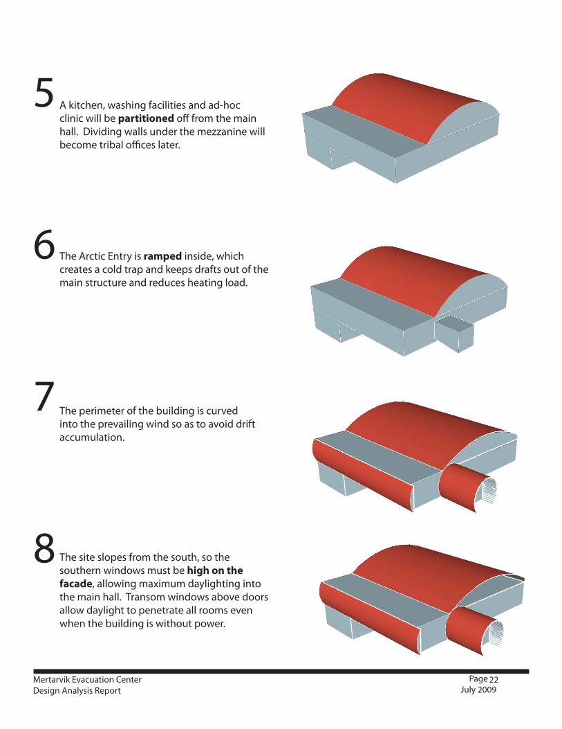
A kitchen, washing facilities and ad-hoc clinic will be partitioned off from the main hall. Dividing walls under the mezzanine will become tribal offices later.
The Arctic Entry is ramped inside, which creates a cold trap and keeps drafts out of the main structure and reduces heating load.
The site slopes from the south, so the southern windows must be high on the facade, allowing maximum daylighting into the main hall. Transom windows above doors allow daylight to penetrate all rooms even when the building is without power.
7
6
5
8
The perimeter of the building is curved into the prevailing wind so as to avoid drift accumulation.
23Mertarvik Evacuation CenterDesign Analysis Report
Page July 2009
The structural design criteria for the building include:
Wind: 120 MPH (Fully Exposed)Seismic: Ss = 0.59, S1 = 0.15 (IBC 2006 design parameters)Ground Snow Load = 70 psf (similar to Nome)Flat Roof Snow = 51 psfImportance factor, I = 1.5Soil Bearing Capacity: Classified NSF fill - 3000 psf, Bed Rock - 4000 psf
The MEC is a hybrid structure, with all-weather wood footings resting on compacted gravel, which in turn rests upon bedrock. For the structure to be sound, all organic and frost susceptible materials must be cleared off the bedrock before fill is added.
The proposed lower floor structural system includes:• Asteelstudframerestingonall-weatherwoodfootings• Lightgaugesteelfloorjoiststhatarelockedinplacewithsoy-basedurethanefoaminsulation.Thejoists are engineered to withstand soil pressures and loads, and detailed to eliminate thermal bridging.• ¾”Tongue-in-grooveflooring• Steelstudframeisbuilt‘inside-out’,with9”ofurethanefoamsprayedagainsttheoutsidesurfaceofthe interior plywood sheathing. The foam will be sprayed past the studs and then the wall will be sprayed with an elastomeric coating and bermed with fill.
It is recommended that the studs be sized and engineered to save on building material. Sheer forces will be handled by the interior sheathing and the urethane insulation, which resists sheer once fully cured. The floor joists, by being locked in by the urethane foam, will also be rigid and resist sheer through diaphragm action. The floor joists will be blocked up 4” above the bearing surface of the footing to allow room for the 9” of insulation. It is important not to spray insulation above the mid-point of the floor joists in section, for once it cures it is difficult to trim down. If the applicator sprays foam to the top edge of the floor joists, it may bulge above the top surface, in which case it would have to be sawed down level in order to install the floor.
The lower floor (Floor 0) has a smaller footprint than the floor above (Floor 1). It is aligned with the north edge of the building so as to enter onto grade on the north side. On the East, West, and South sides, Floor 0 will be below grade. There is an option that a crawlspace could extend from the south wall of Floor 0 until the grade of the bedrock and compacted fill reach the foundation of Floor 1.A load-bearing interior wall carries the vertical loads from the mezzanine columns above down to the foundation, creating rooms for storage and VHF Search and Rescue inside. Floor 0 is thermally isolated from the main building to allow standby minimal heating.
The proposed upper floor structural system includes:• Atimberframeconstructionwithacolumngridof6x6or8x8timbersthattransferverticalloadstobeams along the stud walls below on the north side of the building, and to all-weather wood footings at the south side of the building.
13. STRUCTURAL
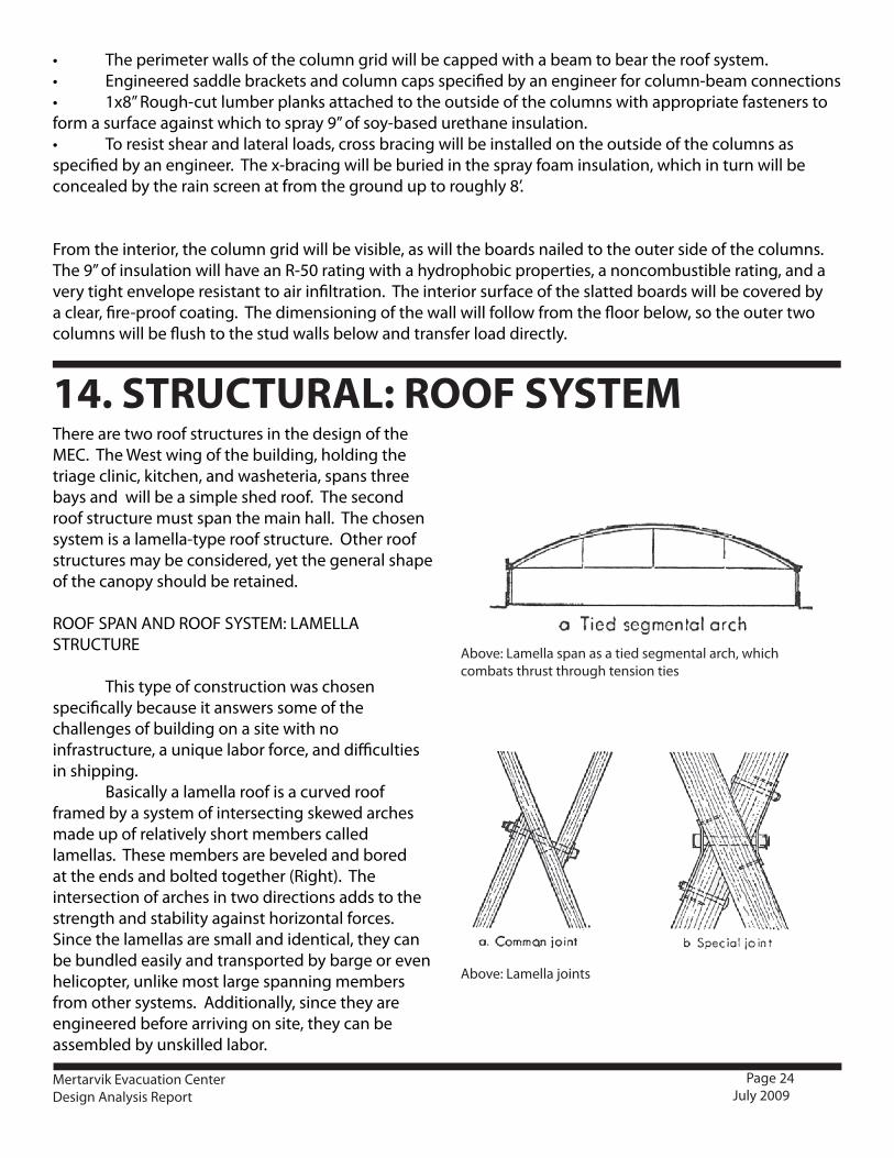
Above: Lamella span as a tied segmental arch, which combats thrust through tension ties
Above: Lamella joints
24Mertarvik Evacuation CenterDesign Analysis Report
Page July 2009
• Theperimeterwallsofthecolumngridwillbecappedwithabeamtobeartheroofsystem.• Engineeredsaddlebracketsandcolumncapsspecifiedbyanengineerforcolumn-beamconnections• 1x8”Rough-cutlumberplanksattachedtotheoutsideofthecolumnswithappropriatefastenerstoform a surface against which to spray 9” of soy-based urethane insulation.• Toresistshearandlateralloads,crossbracingwillbeinstalledontheoutsideofthecolumnsasspecified by an engineer. The x-bracing will be buried in the spray foam insulation, which in turn will be concealed by the rain screen at from the ground up to roughly 8’.
From the interior, the column grid will be visible, as will the boards nailed to the outer side of the columns. The 9” of insulation will have an R-50 rating with a hydrophobic properties, a noncombustible rating, and a very tight envelope resistant to air infiltration. The interior surface of the slatted boards will be covered by a clear, fire-proof coating. The dimensioning of the wall will follow from the floor below, so the outer two columns will be flush to the stud walls below and transfer load directly.
There are two roof structures in the design of the MEC. The West wing of the building, holding the triage clinic, kitchen, and washeteria, spans three bays and will be a simple shed roof. The second roof structure must span the main hall. The chosen system is a lamella-type roof structure. Other roof structures may be considered, yet the general shape of the canopy should be retained.
ROOF SPAN AND ROOF SYSTEM: LAMELLA STRUCTURE
This type of construction was chosen specifically because it answers some of the challenges of building on a site with no infrastructure, a unique labor force, and difficulties in shipping. Basically a lamella roof is a curved roof framed by a system of intersecting skewed arches made up of relatively short members called lamellas. These members are beveled and bored at the ends and bolted together (Right). The intersection of arches in two directions adds to the strength and stability against horizontal forces. Since the lamellas are small and identical, they can be bundled easily and transported by barge or even helicopter, unlike most large spanning members from other systems. Additionally, since they are engineered before arriving on site, they can be assembled by unskilled labor.
14. STRUCTURAL: ROOF SYSTEM

Below: interior aesthetic of lamella roof structure
Above and Below: Lamella roofs are commonly constructed using unskilled and volunteer labor
25Mertarvik Evacuation CenterDesign Analysis Report
Page July 2009
Since the lamella roof is an arch rather than a truss, provision must be made to take care of the horizontal thrust developed. A series of tie rods at the base of the lamella spans the hall laterally and counteracts thrust through tension. In this case, calculations are based on the lamella acting as a tied segmental arch. Additionally, the skewed arches develop a thrust component in the longitudinal direction of the building. These longitudinal components may be resisted by roof decking.
DESIGN OF LAMELLA SYSTEM
It is essential that an experienced engineer run the calculations on the lamella roof, calculating the loads based on the design of a segmental arch. The initial recommendations are for the following:
SPAN 64’•RISE 11’ 6”•RADIUS 50’•LAMELLA 2x12s, 12’ long•
These recommendations are estimates and will need to be calculated by an engineer, who will then specify the size and depth of the members and their connection to the beam. For a sample of calculation process for designing the lamella roof system, see appendix : from ‘Modern Timber Engineering’
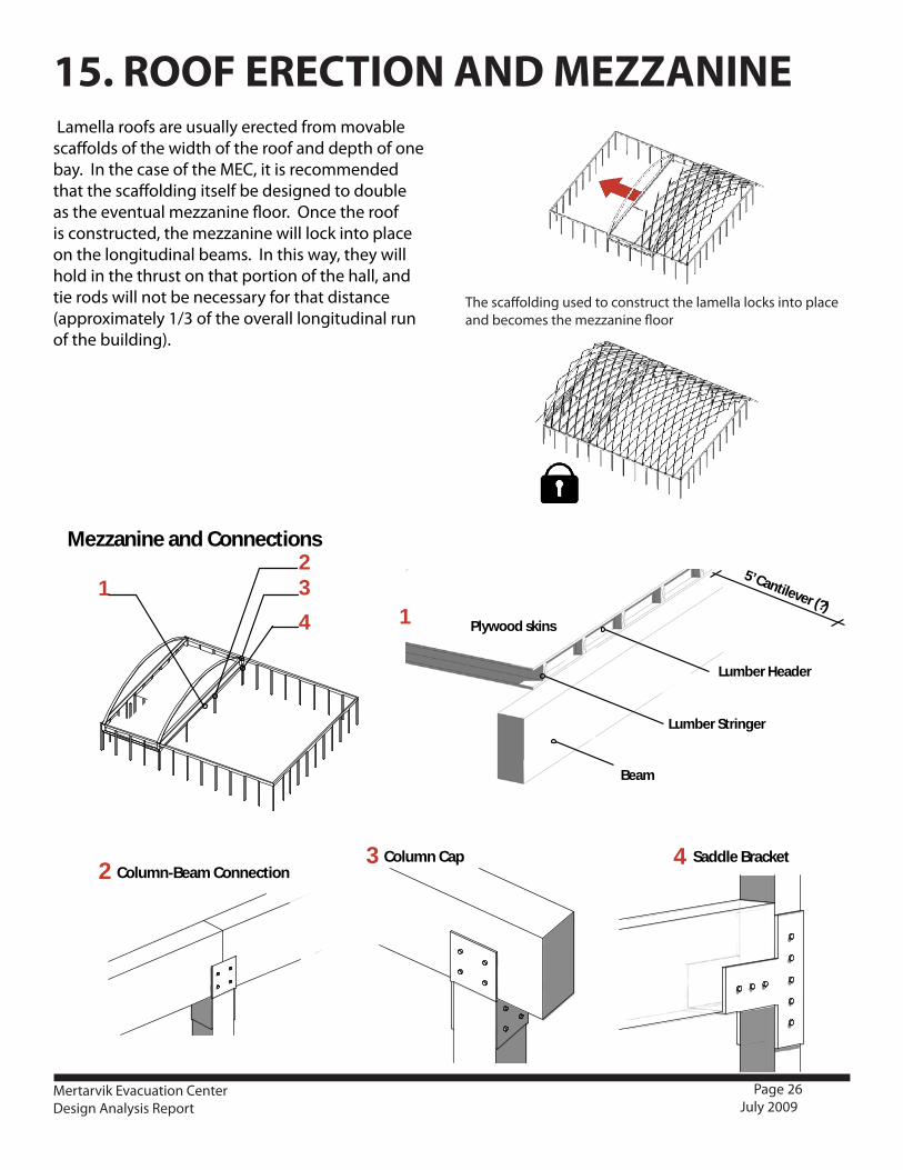
The scaffolding used to construct the lamella locks into place and becomes the mezzanine floor
26Mertarvik Evacuation CenterDesign Analysis Report
Page July 2009
Lamella roofs are usually erected from movable scaffolds of the width of the roof and depth of one bay. In the case of the MEC, it is recommended that the scaffolding itself be designed to double as the eventual mezzanine floor. Once the roof is constructed, the mezzanine will lock into place on the longitudinal beams. In this way, they will hold in the thrust on that portion of the hall, and tie rods will not be necessary for that distance (approximately 1/3 of the overall longitudinal run of the building).
5’ Cantilever (?)1
Lumber Stringer
Beam
Plywood skins
Lumber Header
2 Column-Beam Connection3 Column Cap
1
4
32
Mezzanine and Connections
Lamella Connection
4 Saddle Bracket
15. ROOF ERECTION AND MEZZANINE

27Mertarvik Evacuation CenterDesign Analysis Report
Page July 2009
The 6x6 columns are spaced 8’ on center with column caps to be specified by an engineer. The resulting bay forms the basic structure of the wall assembly.
1x8 rough cut wood planks are attached to the exterior face of the columns. The planks form the surface necessary to spray the insulation against. In this way, the wall assembly is constructed ‘inside-out.’ On the interior, a clear fire-proof coating is applied to the planks. The wood columns and wooden planks form a pleasing interior aesthetic.
Cross-bracing with mechanical connections to the bay resists shear forces on the wall. The cross-bracing will be buried in foam, which has additional shear capacity. Cross-bracing specifications must be engineered.
10” plastic-weld U-bracket spacers are attached on two-foot centers parallel to the column grid with screws. The purpose of the brackets are twofold: they form the armature for the rain screen and give a visual aid to the spray foam applicator on the desired depth of insulation. The spacers can be notched for further visual aid. Plastic-weld is specified instead of metal so as to limit thermal bridging through the insulation.
16. BUILDING ENVELOPE
28Mertarvik Evacuation CenterDesign Analysis Report
Page July 2009
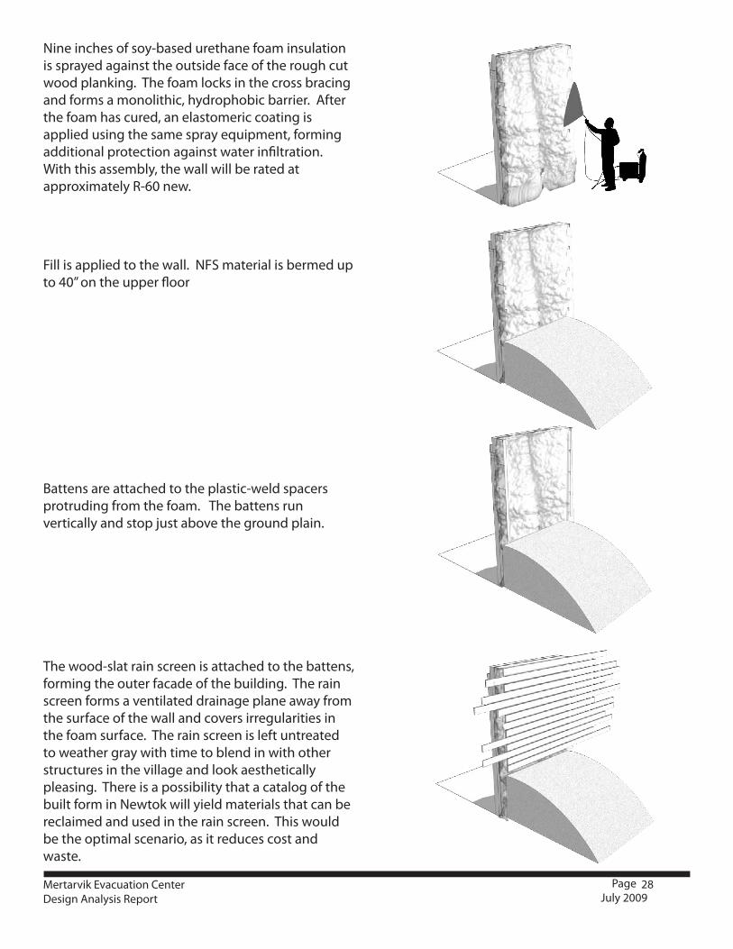
Nine inches of soy-based urethane foam insulation is sprayed against the outside face of the rough cut wood planking. The foam locks in the cross bracing and forms a monolithic, hydrophobic barrier. After the foam has cured, an elastomeric coating is applied using the same spray equipment, forming additional protection against water infiltration. With this assembly, the wall will be rated at approximately R-60 new.
Fill is applied to the wall. NFS material is bermed up to 40” on the upper floor
Battens are attached to the plastic-weld spacers protruding from the foam. The battens run vertically and stop just above the ground plain.
The wood-slat rain screen is attached to the battens, forming the outer facade of the building. The rain screen forms a ventilated drainage plane away from the surface of the wall and covers irregularities in the foam surface. The rain screen is left untreated to weather gray with time to blend in with other structures in the village and look aesthetically pleasing. There is a possibility that a catalog of the built form in Newtok will yield materials that can be reclaimed and used in the rain screen. This would be the optimal scenario, as it reduces cost and waste.
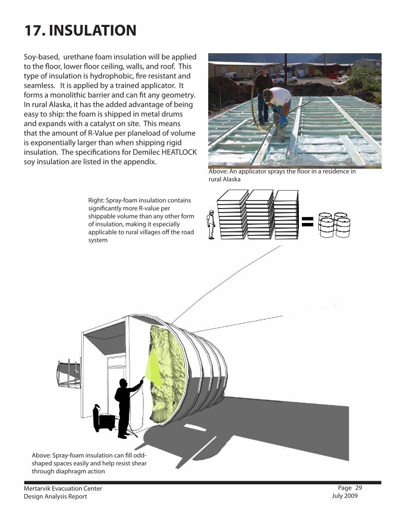
Above: An applicator sprays the floor in a residence in rural Alaska
29Mertarvik Evacuation CenterDesign Analysis Report
Page July 2009
Soy-based, urethane foam insulation will be applied to the floor, lower floor ceiling, walls, and roof. This type of insulation is hydrophobic, fire resistant and seamless. It is applied by a trained applicator. It forms a monolithic barrier and can fit any geometry. In rural Alaska, it has the added advantage of being easy to ship: the foam is shipped in metal drums and expands with a catalyst on site. This means that the amount of R-Value per planeload of volume is exponentially larger than when shipping rigid insulation. The specifications for Demilec HEATLOCK soy insulation are listed in the appendix.
17. INSULATION
Right: Spray-foam insulation contains significantly more R-value per shippable volume than any other form of insulation, making it especially applicable to rural villages off the road system
Above: Spray-foam insulation can fill odd-shaped spaces easily and help resist shear through diaphragm action

Above: Rain Screen and light shelf in section
Above: In summer, the dark boards filter the ever-present light.
Above: In winter, the boards are designed to capture high-albedo snow, which forms a lights shelf in the dark months
Above: Wood weathered by the sea air is a common, authentic and beautiful cladding material in rural Alaska
30
18. EXTERIOR CLADDING
Mertarvik Evacuation CenterDesign Analysis Report
Page July 2009
The exterior cladding of the MEC will consist of a rainscreen of weathered wood arrayed in horizontal slats along the outside of the wall. The rainscreen assembly consists of the following:
Plastic U-brackets that tie back to the interior wall•1/2” vertical battens•Horizontal weathered-wood slats spaces 1/2” •
apart attached to the battensSlats rotated 90 degrees in front of window •
openings to form light shelfThe rain screen provides the following functions:
Provide a drainage plane away from the wall•Provide a ventilated air space between the •
drainage plane and the insulation behind which allows the cladding to breathe and extends the life of the building.
Protect the spray foam insulation from UV rays.•Mask the insulation, which can be irregular and •
difficult to plane.Filter the ever-present summer light.•Accumulate high-albedo snow in the winter, •
forming a light-shelf that reflects snow into the interior of the building.
Provide a fitting aesthetic of ocean-air, weathered •wood common in vernacular and modern village structures. The wood for the rainscreen may be gleaned from the otherwise unusable buildings in the existing village of Newtok. Since it is away from the structural wall assembly, it need not be treated. The weathered wood will function as an additional barrier to the elements and make the building fit the architectural language of rural Alaska.
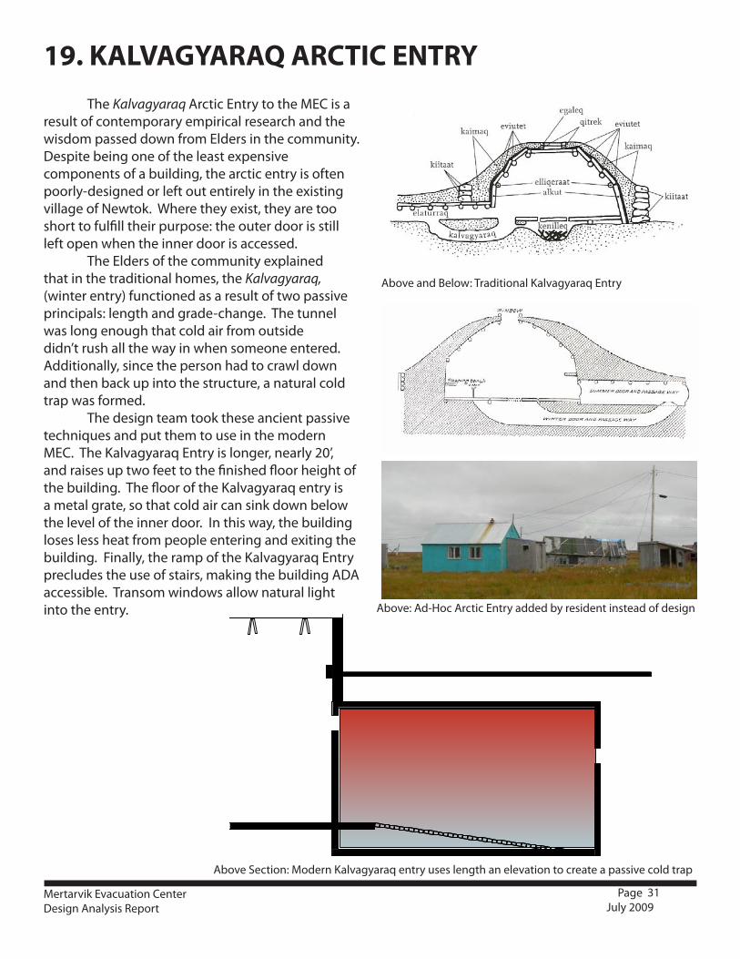
Above and Below: Traditional Kalvagyaraq Entry
Above: Ad-Hoc Arctic Entry added by resident instead of design
Above Section: Modern Kalvagyaraq entry uses length an elevation to create a passive cold trap
31Mertarvik Evacuation CenterDesign Analysis Report
Page July 2009
The Kalvagyaraq Arctic Entry to the MEC is a result of contemporary empirical research and the wisdom passed down from Elders in the community. Despite being one of the least expensive components of a building, the arctic entry is often poorly-designed or left out entirely in the existing village of Newtok. Where they exist, they are too short to fulfill their purpose: the outer door is still left open when the inner door is accessed. The Elders of the community explained that in the traditional homes, the Kalvagyaraq, (winter entry) functioned as a result of two passive principals: length and grade-change. The tunnel was long enough that cold air from outside didn’t rush all the way in when someone entered. Additionally, since the person had to crawl down and then back up into the structure, a natural cold trap was formed. The design team took these ancient passive techniques and put them to use in the modern MEC. The Kalvagyaraq Entry is longer, nearly 20’, and raises up two feet to the finished floor height of the building. The floor of the Kalvagyaraq entry is a metal grate, so that cold air can sink down below the level of the inner door. In this way, the building loses less heat from people entering and exiting the building. Finally, the ramp of the Kalvagyaraq Entry precludes the use of stairs, making the building ADA accessible. Transom windows allow natural light into the entry.
19. KALVAGYARAQ ARCTIC ENTRY
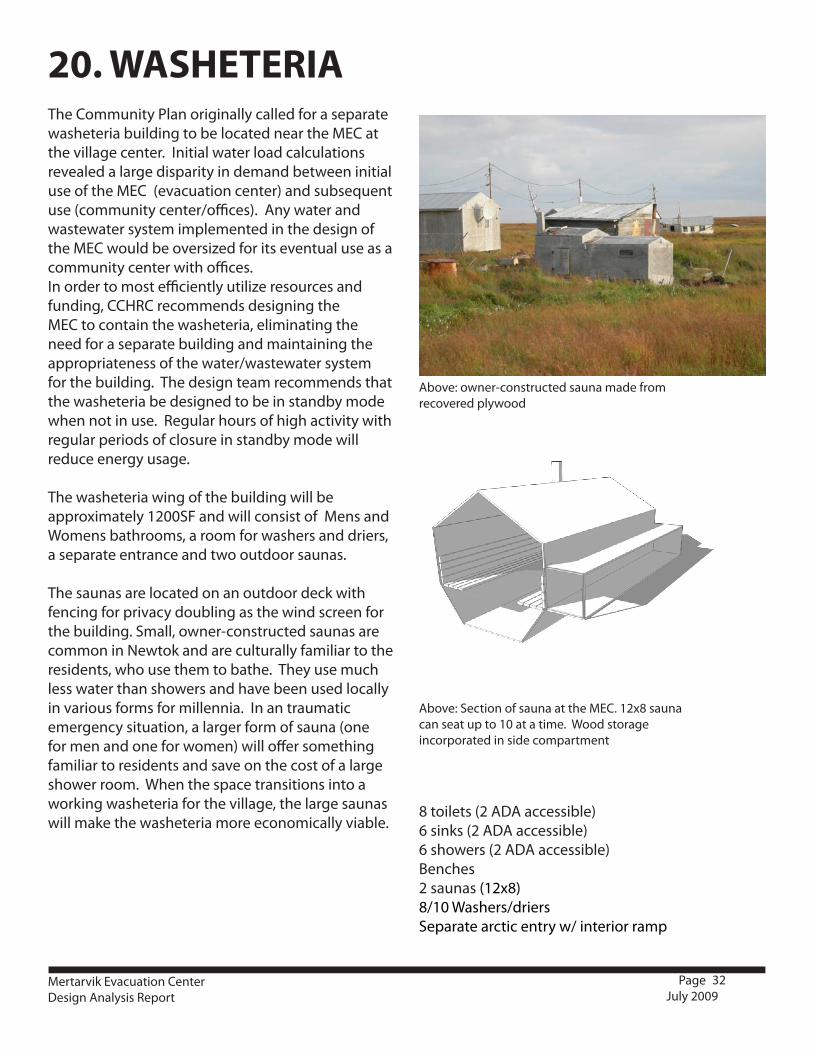
Above: owner-constructed sauna made from recovered plywood
Above: Section of sauna at the MEC. 12x8 sauna can seat up to 10 at a time. Wood storage incorporated in side compartment
32Mertarvik Evacuation CenterDesign Analysis Report
Page July 2009
20. WASHETERIAThe Community Plan originally called for a separate washeteria building to be located near the MEC at the village center. Initial water load calculations revealed a large disparity in demand between initial use of the MEC (evacuation center) and subsequent use (community center/offices). Any water and wastewater system implemented in the design of the MEC would be oversized for its eventual use as a community center with offices.In order to most efficiently utilize resources and funding, CCHRC recommends designing the MEC to contain the washeteria, eliminating the need for a separate building and maintaining the appropriateness of the water/wastewater system for the building. The design team recommends that the washeteria be designed to be in standby mode when not in use. Regular hours of high activity with regular periods of closure in standby mode will reduce energy usage.
The washeteria wing of the building will be approximately 1200SF and will consist of Mens and Womens bathrooms, a room for washers and driers, a separate entrance and two outdoor saunas.
The saunas are located on an outdoor deck with fencing for privacy doubling as the wind screen for the building. Small, owner-constructed saunas are common in Newtok and are culturally familiar to the residents, who use them to bathe. They use much less water than showers and have been used locally in various forms for millennia. In an traumatic emergency situation, a larger form of sauna (one for men and one for women) will offer something familiar to residents and save on the cost of a large shower room. When the space transitions into a working washeteria for the village, the large saunas will make the washeteria more economically viable.
8 toilets (2 ADA accessible)6 sinks (2 ADA accessible)6 showers (2 ADA accessible)Benches2 saunas (12x8)8/10 Washers/driersSeparate arctic entry w/ interior ramp
33Mertarvik Evacuation CenterDesign Analysis Report
Page July 2009
21.1 RECOMMENDATIONSAs stated above, the large variation in occupant load based on the three separate occupation scenarios creates the primary design challenge in the mechanical system of the building. Due to these disparate loads, the design team recommends that the mechanical systems operate zonally. The design should incorporate the use of many identically-sized units in a series. The heaters should be redundant, high efficiency, direct-vent, sealed combustion oil-fired space heaters. The redundancy of the design allows as a whole to operate only where needed - at the level needed. This also provides a level of system redundancy important in emergency situations. In the event there is a malfunction in any one unit, the redundant system will keep the space inhabitable. In a single zone system, a malfunction during an emergency would be devastating; additionally, the system would be oversized and inefficient as the building transitions into its second life as a community center. With a multiple-zone system, the remaining units provide for the space while the malfunctioning unit is being repaired. The design must provide a mechanism that would allow the systems to be decommissioned, or operate at minimum levels when the space is not in use. These key features provide greater flexibility, ease of maintenance, and energy-efficiency.
21.2 SPACE HEATINGCritical mechanical elements located in the basement should be kept above freezing when building is unoccupied. The heating system should be designed to operate at minimal energy levels when in stand-by mode. Heat should be provided zonally, with space heating appliances, all the same size, that are appropriately sized for the intended zones. By employing system redundancy, reliance on one appliance as a heat source is avoided. A high efficiency direct vent oil heating appliance is recommended, sized according to the energy model contained in this report.
21.3 VENTILATIONVentilation should be sized to operate in a series so in a storm event or an emergency the air handler will be able to handle ventilation and heat for a short period of time. High efficient heat ventilation operating zonally is the recommended design approach. In most cases of lower occupancy loads, properly-sized heat recovery ventilators are recommended to be designed with multiple-series configuration. This allows the system to address varying output scenarios, i.e.-fewer occupants/less ventilation, 0 occupants/minimum ventilation.
21.4 HOT WATERHot water is the greatest consumer of energy, providing as much as 80% of total energy use. Because the stand-by use of energy, in hot water systems, is very significant, the design and usage strategy will require an innovative approach. One non-architectural tactic to consider would be establishing a regular schedule for washeteria use. During specified periods of time, the hot water in the washeteria would be completely shut off. It would only be open to meet the requirements of the village during predetermined periods of high volume use. This would not affect the outdoor public saunas.
21. MECHANICAL

34Mertarvik Evacuation CenterDesign Analysis Report
Page July 2009
22.1 RECOMMENDATIONS
All appliances, lighting, and mechanical components using electric power, need to be selected based on their energy efficiencies. Switching and controls should be installed that will shut off power when they are not in use. It is imperative that the person who will be in charge of managing the building is properly trained and have a clear understanding of the energy efficiency features of the facility. Operations Manuals should be clear, available and stored in the building. A major consideration is the possible variation of the occupancy load of the building. The recommendations provided will allow the building to function most efficiently at varying loads.
22.2 LIGHTINGThe design team strongly encourages the use of LED’s in lighting design. LED’s are smaller, last longer, and use less energy than traditional incandescent bulbs. Currently, LED’s are more expensive than incandescents/CFLs - but pricing has become significantly more affordable when life-cycle cost is factored. It is expected that this trend will continue so that by construction time, costs for LED’s should be within a reasonable range of incandescent lighting. The switching and lighting layout design should provide only an adequate amount of lumens for current occupants. It is also suggested that much lighting be motion-activated with ambient light detectors. So that when no one is in the building, no lights are on except any necessary emergency lighting.
22.3 APPLIANCESWater usage and energy consumption should be the greatest consideration when choosing appliances. Particularly when selecting appliances for the washeteria, total energy use, including water, should be a major factor in any final decision. WThe design team recommends that in the additional planning process, designers work very closely with Lifewater Engineering to ensure the wastewater system can effectively function at varying levels and is capable of a standby setting. These considerations will help avoid significant power drain from the system when the building functions as a community center.
22.4 POWER GENERATIONIn order to maintain 50° F in the Floor 0 mechanical area, a power source is necessary. The design team recommends having 2-3 small diesel generators that are sized to meet a variety of demands in series (such as (2)- 6 kw or (3)- 4 kw units). This will also ensure that there is a backup generator if one fails.
The design team recommends a system that uses a generator, an inverter, and a battery bank. One generator can charge the battery bank for continual standby power to keep the mechanical area ready for an emergency event. This system can be designed so that the generator runs intermittently to recharge the batteries. This system can also incorporate seasonal solar energy or the planned wind farm. There will be a minimal amount of electricity needed to keep the mechanical lower level above freezing and the generators warm for starting in an emergency situation. The battery bank inverter scenario would be the best in our estimation, to satisfy this demand.
22. ELECTRICAL
35Mertarvik Evacuation CenterDesign Analysis Report
Page July 2009
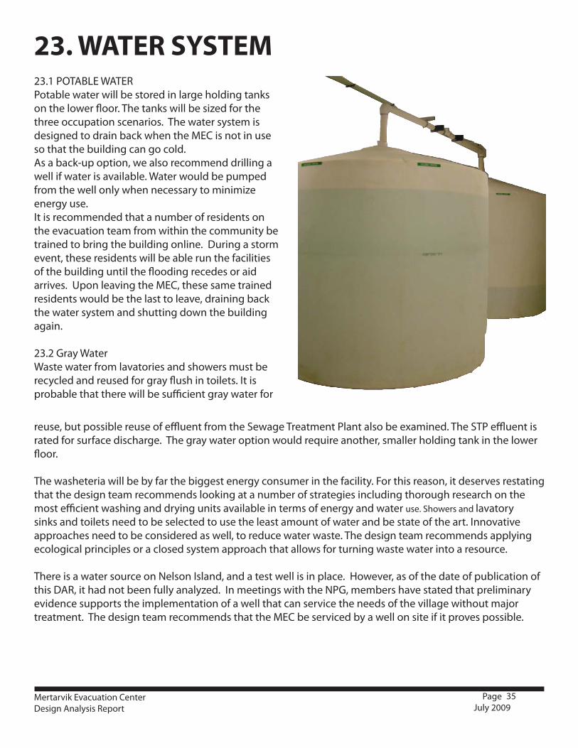
reuse, but possible reuse of effluent from the Sewage Treatment Plant also be examined. The STP effluent is rated for surface discharge. The gray water option would require another, smaller holding tank in the lower floor.
The washeteria will be by far the biggest energy consumer in the facility. For this reason, it deserves restating that the design team recommends looking at a number of strategies including thorough research on the most efficient washing and drying units available in terms of energy and water use. Showers and lavatory sinks and toilets need to be selected to use the least amount of water and be state of the art. Innovative approaches need to be considered as well, to reduce water waste. The design team recommends applying ecological principles or a closed system approach that allows for turning waste water into a resource.
There is a water source on Nelson Island, and a test well is in place. However, as of the date of publication of this DAR, it had not been fully analyzed. In meetings with the NPG, members have stated that preliminary evidence supports the implementation of a well that can service the needs of the village without major treatment. The design team recommends that the MEC be serviced by a well on site if it proves possible.
23.1 POTABLE WATERPotable water will be stored in large holding tanks on the lower floor. The tanks will be sized for the three occupation scenarios. The water system is designed to drain back when the MEC is not in use so that the building can go cold.As a back-up option, we also recommend drilling a well if water is available. Water would be pumped from the well only when necessary to minimize energy use. It is recommended that a number of residents on the evacuation team from within the community be trained to bring the building online. During a storm event, these residents will be able run the facilities of the building until the flooding recedes or aid arrives. Upon leaving the MEC, these same trained residents would be the last to leave, draining back the water system and shutting down the building again.
23.2 Gray WaterWaste water from lavatories and showers must be recycled and reused for gray flush in toilets. It is probable that there will be sufficient gray water for
23. WATER SYSTEM

36Mertarvik Evacuation CenterDesign Analysis Report
Page July 2009
24.1 DESIGN CRITERIA The design of the wastewater treatment system of the MEC is based on the following criteria:
It must function as a ‘stand-alone’ building before village infrastructure is implemented•It must have the ability to drain back and go cold when not in use•It must have the capacity to deal with the varying loads put on it by the three occupation scenarios•It must be able to deal with effluent before the village has the capacity to dispose of it using conventional •
methods.
For these reasons, the design team recommends implementing an on-site sewage treatment plant. The engineering partners used in designing this plant are Lifewater Engineering: 1963 Donald Avenue, Fairbanks Alaska, 99701. It was designed by Bob Tsigonis and Jason Rowland of Lifewater Engineering.
The design criteria used to size the wastewater treatment systems is based on the largest probable hydraulic load that may occur during an emergency when 300 people are expected to use the treatment system for all domestic water needs. Water use is expected to be 25 gallons per capita per day (gpcd) during an emergency relocation requiring that the treatment plant be able to process 7500 gallons per day (gpd). On-Site Wastewater Treatment SystemWastewater from the washeteria will flow to the treatment system either by gravity or from a lift station. The system will consist of two ISO shipping containers, transported separately but connected together onsite. Wastewater will flow into the first container, where it will be pre-screened before flowing on to the bioreactor tank. The bioreactor will be sized to meet the maximum daily flow (7500 gallons). The operating level will be at 3750 gallons, with an additional 3750 gallons of surge capacity. As the system operates and the microbiology grows, accumulated solids will have to be periodically removed from the system. The second container would house the membrane filtration and effluent discharge components where the contents of the bioreactor tank would be circulated through an ultrafiltration membrane. Treated wastewater that passes through the membrane filter can be discharged to a surface location under an APDES permit issued by the Alaska Department of Environmental Conservation. Wastewater Treatment Description
The proposed wastewater treatment system consists of four individual treatment steps: 1. Pre-screening of influentThis process will utilize a mechanical influent screen to remove much of the larger solids, trash, and other material that could interfere with downstream processes. Solids removed by the screen will be automatically placed in a bag for periodic manual removal. Mechanical pre-screening eliminates the need for a settling tank, and automatic screen cleaning and solids bagging reduce maintenance requirements.2. Biological reduction of biological oxygen demand (BOD) in an aerated tank BOD reduction will occur in a 7500 gallon aerated tank. An air blower will supply the oxygen needed by microorganisms to break down the organic material (BOD) in the wastewater. The single compartment bioreactor can operate at sludge concentrations up to 2.0 percent. No additional treatment tanks are need for this process and the only maintenance required is periodic removal of accumulated sludge. 3. Membrane filtration using ultrafiltration membrane modulesNorit X-Flow tubular ultrafiltration membrane modules provide a high quality, particle free effluent for surface discharge. This system has proven to be ideal for treating wastewater in the arctic climates and has been successfully implemented in oil exploration camps that require rapid startup and consistently high quality effluent. Unlike traditional systems, which can take months before the biological media is
24. SEWAGE TREATMENT PLANT
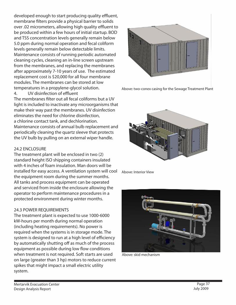
37
Above: two-conex casing for the Sewage Treatment Plant
Above: Interior View
Above: skid mechanism
Mertarvik Evacuation CenterDesign Analysis Report
Page July 2009
developed enough to start producing quality effluent, membrane filters provide a physical barrier to solids over .02 micrometers, allowing high quality effluent to be produced within a few hours of initial startup. BOD and TSS concentration levels generally remain below 5.0 ppm during normal operation and fecal coliform levels generally remain below detectable limits. Maintenance consists of running periodic automated cleaning cycles, cleaning an in-line screen upstream from the membranes, and replacing the membranes after approximately 7-10 years of use. The estimated replacement cost is $20,000 for all four membrane modules. The membranes can be stored at low temperatures in a propylene-glycol solution.4. UV disinfection of effluent The membranes filter out all fecal coliforms but a UV light is included to inactivate any microorganisms that make their way past the membranes. UV disinfection eliminates the need for chlorine disinfection, a chlorine contact tank, and dechlorination. Maintenance consists of annual bulb replacement and periodically cleaning the quartz sleeve that protects the UV bulb by pulling on an external wiper handle.
24.2 ENCLOSUREThe treatment plant will be enclosed in two (2) standard height ISO shipping containers insulated with 4 inches of foam insulation. Man doors will be installed for easy access. A ventilation system will cool the equipment room during the summer months. All tanks and process equipment can be operated and serviced from inside the enclosure allowing the operator to perform maintenance procedures in a protected environment during winter months.
24.3 POWER REQUIREMENTSThe treatment plant is expected to use 1000-6000 kW-hours per month during normal operation (including heating requirements). No power is required when the systems is in storage mode. The system is designed to run at a high level of efficiency by automatically shutting off as much of the process equipment as possible during low flow conditions when treatment is not required. Soft starts are used on large (greater than 3 hp) motors to reduce current spikes that might impact a small electric utility system.
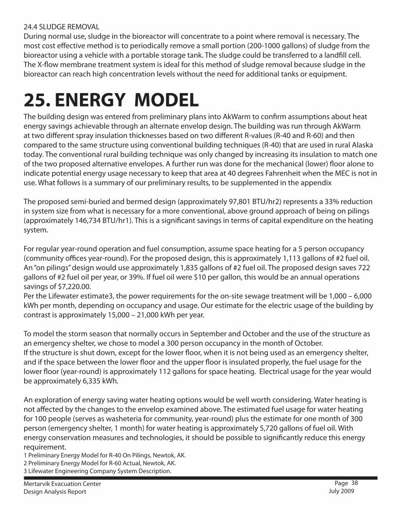
38Mertarvik Evacuation CenterDesign Analysis Report
Page July 2009
The building design was entered from preliminary plans into AkWarm to confirm assumptions about heat energy savings achievable through an alternate envelop design. The building was run through AkWarm at two different spray insulation thicknesses based on two different R-values (R-40 and R-60) and then compared to the same structure using conventional building techniques (R-40) that are used in rural Alaska today. The conventional rural building technique was only changed by increasing its insulation to match one of the two proposed alternative envelopes. A further run was done for the mechanical (lower) floor alone to indicate potential energy usage necessary to keep that area at 40 degrees Fahrenheit when the MEC is not in use. What follows is a summary of our preliminary results, to be supplemented in the appendix
The proposed semi-buried and bermed design (approximately 97,801 BTU/hr2) represents a 33% reduction in system size from what is necessary for a more conventional, above ground approach of being on pilings (approximately 146,734 BTU/hr1). This is a significant savings in terms of capital expenditure on the heating system.
For regular year-round operation and fuel consumption, assume space heating for a 5 person occupancy (community offices year-round). For the proposed design, this is approximately 1,113 gallons of #2 fuel oil. An “on pilings” design would use approximately 1,835 gallons of #2 fuel oil. The proposed design saves 722 gallons of #2 fuel oil per year, or 39%. If fuel oil were $10 per gallon, this would be an annual operations savings of $7,220.00.Per the Lifewater estimate3, the power requirements for the on-site sewage treatment will be 1,000 – 6,000 kWh per month, depending on occupancy and usage. Our estimate for the electric usage of the building by contrast is approximately 15,000 – 21,000 kWh per year.
To model the storm season that normally occurs in September and October and the use of the structure as an emergency shelter, we chose to model a 300 person occupancy in the month of October. If the structure is shut down, except for the lower floor, when it is not being used as an emergency shelter, and if the space between the lower floor and the upper floor is insulated properly, the fuel usage for the lower floor (year-round) is approximately 112 gallons for space heating. Electrical usage for the year would be approximately 6,335 kWh.
An exploration of energy saving water heating options would be well worth considering. Water heating is not affected by the changes to the envelop examined above. The estimated fuel usage for water heating for 100 people (serves as washeteria for community, year-round) plus the estimate for one month of 300 person (emergency shelter, 1 month) for water heating is approximately 5,720 gallons of fuel oil. With energy conservation measures and technologies, it should be possible to significantly reduce this energy requirement.1 Preliminary Energy Model for R-40 On Pilings, Newtok, AK.2 Preliminary Energy Model for R-60 Actual, Newtok, AK.3 Lifewater Engineering Company System Description.
25. ENERGY MODEL
24.4 SLUDGE REMOVALDuring normal use, sludge in the bioreactor will concentrate to a point where removal is necessary. The most cost effective method is to periodically remove a small portion (200-1000 gallons) of sludge from the bioreactor using a vehicle with a portable storage tank. The sludge could be transferred to a landfill cell. The X-flow membrane treatment system is ideal for this method of sludge removal because sludge in the bioreactor can reach high concentration levels without the need for additional tanks or equipment.
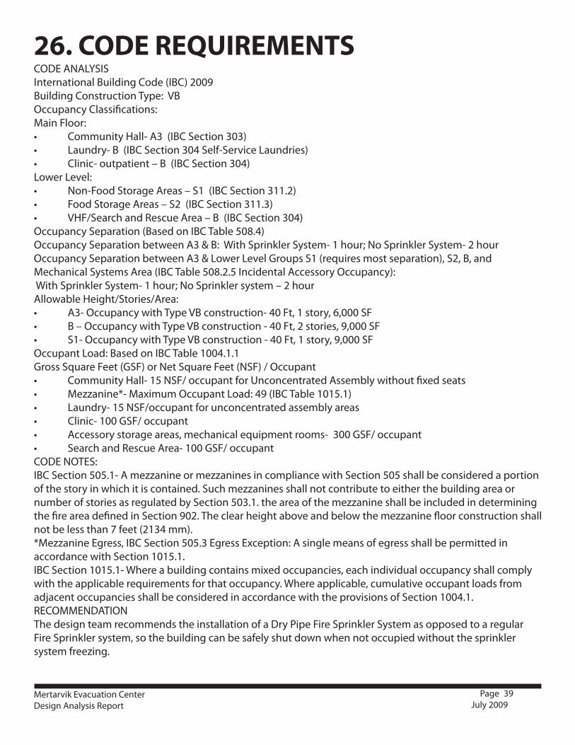
39Mertarvik Evacuation CenterDesign Analysis Report
Page July 2009
CODE ANALYSISInternational Building Code (IBC) 2009Building Construction Type: VB Occupancy Classifications:Main Floor:• CommunityHall-A3(IBCSection303)• Laundry-B(IBCSection304Self-ServiceLaundries)• Clinic-outpatient–B(IBCSection304)Lower Level:• Non-FoodStorageAreas–S1(IBCSection311.2)• FoodStorageAreas–S2(IBCSection311.3)• VHF/SearchandRescueArea–B(IBCSection304)Occupancy Separation (Based on IBC Table 508.4)Occupancy Separation between A3 & B: With Sprinkler System- 1 hour; No Sprinkler System- 2 hourOccupancy Separation between A3 & Lower Level Groups S1 (requires most separation), S2, B, and Mechanical Systems Area (IBC Table 508.2.5 Incidental Accessory Occupancy): With Sprinkler System- 1 hour; No Sprinkler system – 2 hourAllowable Height/Stories/Area:• A3-OccupancywithTypeVBconstruction-40Ft,1story,6,000SF• B–OccupancywithTypeVBconstruction-40Ft,2stories,9,000SF• S1-OccupancywithTypeVBconstruction-40Ft,1story,9,000SFOccupant Load: Based on IBC Table 1004.1.1Gross Square Feet (GSF) or Net Square Feet (NSF) / Occupant • CommunityHall-15NSF/occupantforUnconcentratedAssemblywithoutfixedseats• Mezzanine*-MaximumOccupantLoad:49(IBCTable1015.1)• Laundry-15NSF/occupantforunconcentratedassemblyareas• Clinic-100GSF/occupant• Accessorystorageareas,mechanicalequipmentrooms-300GSF/occupant• SearchandRescueArea-100GSF/occupantCODE NOTES:IBC Section 505.1- A mezzanine or mezzanines in compliance with Section 505 shall be considered a portion of the story in which it is contained. Such mezzanines shall not contribute to either the building area or number of stories as regulated by Section 503.1. the area of the mezzanine shall be included in determining the fire area defined in Section 902. The clear height above and below the mezzanine floor construction shall not be less than 7 feet (2134 mm).*MezzanineEgress,IBCSection505.3EgressException:Asinglemeansofegressshallbepermittedinaccordance with Section 1015.1. IBC Section 1015.1- Where a building contains mixed occupancies, each individual occupancy shall comply with the applicable requirements for that occupancy. Where applicable, cumulative occupant loads from adjacent occupancies shall be considered in accordance with the provisions of Section 1004.1.RECOMMENDATIONThe design team recommends the installation of a Dry Pipe Fire Sprinkler System as opposed to a regular Fire Sprinkler system, so the building can be safely shut down when not occupied without the sprinkler system freezing.
26. CODE REQUIREMENTS

40
CSI Division Estimated Cost
350,000.00$01300 Administrative Requirements
01500 Temporary Facilities and Controls
340,000.00$02070 Geostextiles
02230 Sod Stripping and Stockpiling of Soil
02300 Earthwork
02450 Foundation & Load Bearing Element
02500 Utility Service
02900 Planting
Division 3: Concrete Not Applicable
Division 4: Masonry Not Applicable
Division 5: Metals 18,000.00$05050 Basic Metal Materials and Methods
05100 Structural Metal Framing
05250 Aluminum Joist
05500 Metal Fabrication
Division 6: Wood and Plastics 650,000.00$06050 Basic Wood & Plastic Materials & Methods
06100 Rough Carpentry
06200 Finish Carpentry
06400 Architectural Woodwork
06500 Structural Plastics
06600 Plastic Fabrications
Division 7: Thermal and Moisture Protection 340,000.00$07050 Basic Thermal & Moisture Protection Materials &Methods
07100 Damproofing and Waterproofing
Division 1: General Requirements
Division 2: Site Construction
Construction cost estimates based on the 35% design drawings andforced account construction. Current market price for materials andlabor was used for this estimate. Labor may vary considerably dependingon the structure of the labor force. For this estimate prevailing unionscale was used. Transportation was not included. The cost estimate hasbeen broken down into the 16 CSI Divisions with examples of what isincluded in each division listed below.
Construction Cost Estimate
27. COST ESTIMATES
Mertarvik Evacuation CenterDesign Analysis Report
Page July 2009
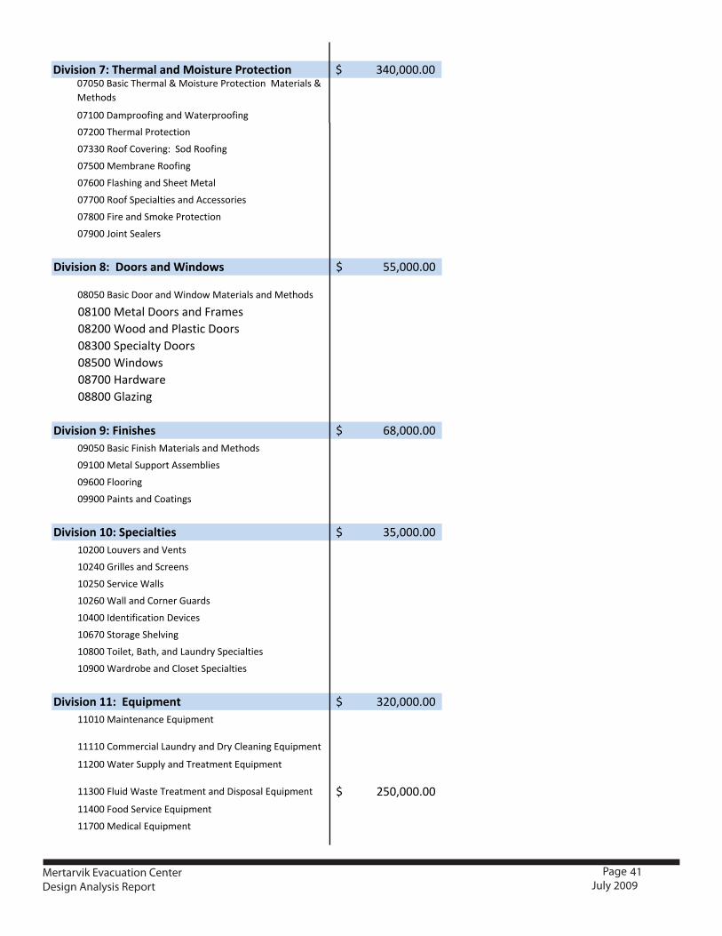
41
CSI Division Estimated Cost
350,000.00$01300 Administrative Requirements
01500 Temporary Facilities and Controls
340,000.00$02070 Geostextiles
02230 Sod Stripping and Stockpiling of Soil
02300 Earthwork
02450 Foundation & Load Bearing Element
02500 Utility Service
02900 Planting
Division 3: Concrete Not Applicable
Division 4: Masonry Not Applicable
Division 5: Metals 18,000.00$05050 Basic Metal Materials and Methods
05100 Structural Metal Framing
05250 Aluminum Joist
05500 Metal Fabrication
Division 6: Wood and Plastics 650,000.00$06050 Basic Wood & Plastic Materials & Methods
06100 Rough Carpentry
06200 Finish Carpentry
06400 Architectural Woodwork
06500 Structural Plastics
06600 Plastic Fabrications
Division 7: Thermal and Moisture Protection 340,000.00$07050 Basic Thermal & Moisture Protection Materials &Methods
07100 Damproofing and Waterproofing
Division 1: General Requirements
Division 2: Site Construction
Construction cost estimates based on the 35% design drawings andforced account construction. Current market price for materials andlabor was used for this estimate. Labor may vary considerably dependingon the structure of the labor force. For this estimate prevailing unionscale was used. Transportation was not included. The cost estimate hasbeen broken down into the 16 CSI Divisions with examples of what isincluded in each division listed below.
Construction Cost Estimate
07200 Thermal Protection
07330 Roof Covering: Sod Roofing
07500 Membrane Roofing
07600 Flashing and Sheet Metal
07700 Roof Specialties and Accessories
07800 Fire and Smoke Protection
07900 Joint Sealers
Division 8: Doors and Windows 55,000.00$
08050 Basic Door and Window Materials and Methods
08100 Metal Doors and Frames08200 Wood and Plastic Doors08300 Specialty Doors08500 Windows08700 Hardware08800 Glazing
Division 9: Finishes 68,000.00$09050 Basic Finish Materials and Methods
09100 Metal Support Assemblies
09600 Flooring
09900 Paints and Coatings
Division 10: Specialties 35,000.00$10200 Louvers and Vents
10240 Grilles and Screens
10250 Service Walls
10260 Wall and Corner Guards
10400 Identification Devices
10670 Storage Shelving
10800 Toilet, Bath, and Laundry Specialties
10900 Wardrobe and Closet Specialties
Division 11: Equipment 320,000.00$11010 Maintenance Equipment
11110 Commercial Laundry and Dry Cleaning Equipment
11200 Water Supply and Treatment Equipment
11300 Fluid Waste Treatment and Disposal Equipment 250,000.00$11400 Food Service Equipment
11700 Medical Equipment
Division 12: Furnishings $
Division 13: Special Construction 150,000.00$13030 Special Purpose Rooms: Cold Storage
13100 Lightning Protection
Mertarvik Evacuation CenterDesign Analysis Report
Page July 2009
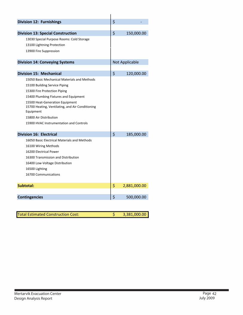
42
07200 Thermal Protection
07330 Roof Covering: Sod Roofing
07500 Membrane Roofing
07600 Flashing and Sheet Metal
07700 Roof Specialties and Accessories
07800 Fire and Smoke Protection
07900 Joint Sealers
Division 8: Doors and Windows 55,000.00$
08050 Basic Door and Window Materials and Methods
08100 Metal Doors and Frames08200 Wood and Plastic Doors08300 Specialty Doors08500 Windows08700 Hardware08800 Glazing
Division 9: Finishes 68,000.00$09050 Basic Finish Materials and Methods
09100 Metal Support Assemblies
09600 Flooring
09900 Paints and Coatings
Division 10: Specialties 35,000.00$10200 Louvers and Vents
10240 Grilles and Screens
10250 Service Walls
10260 Wall and Corner Guards
10400 Identification Devices
10670 Storage Shelving
10800 Toilet, Bath, and Laundry Specialties
10900 Wardrobe and Closet Specialties
Division 11: Equipment 320,000.00$11010 Maintenance Equipment
11110 Commercial Laundry and Dry Cleaning Equipment
11200 Water Supply and Treatment Equipment
11300 Fluid Waste Treatment and Disposal Equipment 250,000.00$11400 Food Service Equipment
11700 Medical Equipment
Division 12: Furnishings $
Division 13: Special Construction 150,000.00$13030 Special Purpose Rooms: Cold Storage
13100 Lightning Protection
13900 Fire Suppression
Division 14: Conveying Systems Not Applicable
Division 15: Mechanical 120,000.00$15050 Basic Mechanical Materials and Methods
15100 Building Service Piping
15300 Fire Protection Piping
15400 Plumbing Fixtures and Equipment
15500 Heat Generation Equipment15700 Heating, Ventilating, and Air ConditioningEquipment
15800 Air Distribution
15900 HVAC Instrumentation and Controls
Division 16: Electrical 185,000.00$16050 Basic Electrical Materials and Methods
16100 Wiring Methods
16200 Electrical Power
16300 Transmission and Distribution
16400 Low Voltage Distribution
16500 Lighting
16700 Communications
Subtotal: 2,881,000.00$
Contingencies 500,000.00$
Total Estimated Construction Cost: 3,381,000.00$
Mertarvik Evacuation CenterDesign Analysis Report
Page July 2009