Contents The Macroscopic Nature of a Fluid: ... Chapter 13 Foundations of Fluid ... Liquids vs....
51
Contents V FLUID MECHANICS ii 13 Foundations of Fluid Dynamics 1 13.1 Overview ...................................... 1 13.2 The Macroscopic Nature of a Fluid: Density, Pressure, Flow Velocity; Liquids vs. Gases ...................................... 3 13.3 Hydrostatics .................................... 7 13.3.1 Archimedes’ Law ............................. 8 13.3.2 Stars and Planets ............................. 9 13.3.3 Hydrostatics of Rotating Fluids ..................... 11 13.4 Conservation Laws ................................ 15 13.5 The Dynamics of an Ideal Fluid ......................... 19 13.5.1 Mass Conservation ............................ 19 13.5.2 Momentum Conservation ......................... 20 13.5.3 Euler Equation .............................. 20 13.5.4 Bernoulli’s Theorem; Expansion, Vorticity and Shear ......... 21 13.5.5 Pitot Tube ................................. 24 13.5.6 Conservation of Energy .......................... 24 13.5.7 Joule-Kelvin Method of Cooling a Real Gas .............. 26 13.6 Incompressible Flows ............................... 29 13.7 Viscous Flows with Heat Conduction ...................... 32 13.7.1 Decomposition of the Velocity Gradient ................. 32 13.7.2 Navier-Stokes Equation .......................... 33 13.7.3 Energy conservation and entropy production .............. 35 13.7.4 Molecular Origin of Viscosity ...................... 36 13.7.5 Reynolds’ Number ............................ 37 13.7.6 Pipe Flow ................................. 37 13.8 T2 Relativistic Dynamics of an Ideal Fluid .................. 39 13.8.1 T2 Stress-Energy Tensor and Equations of Relativistic Fluid Mechanics 39 13.8.2 T2 Relativistic Bernoulli Equation and Ultrarelativistic Astrophysi- cal Jets .................................. 40 13.8.3 T2 Nonrelativistic Limit of the Stress-Energy Tensor ........ 42 i
-
Upload
truongtuyen -
Category
Documents
-
view
214 -
download
0
Transcript of Contents The Macroscopic Nature of a Fluid: ... Chapter 13 Foundations of Fluid ... Liquids vs....

Contents
V FLUID MECHANICS ii
13 Foundations of Fluid Dynamics 113.1 Overview . . . . . . . . . . . . . . . . . . . . . . . . . . . . . . . . . . . . . . 113.2 The Macroscopic Nature of a Fluid: Density, Pressure, Flow Velocity; Liquids
vs. Gases . . . . . . . . . . . . . . . . . . . . . . . . . . . . . . . . . . . . . . 313.3 Hydrostatics . . . . . . . . . . . . . . . . . . . . . . . . . . . . . . . . . . . . 7
13.3.1 Archimedes’ Law . . . . . . . . . . . . . . . . . . . . . . . . . . . . . 813.3.2 Stars and Planets . . . . . . . . . . . . . . . . . . . . . . . . . . . . . 913.3.3 Hydrostatics of Rotating Fluids . . . . . . . . . . . . . . . . . . . . . 11
13.4 Conservation Laws . . . . . . . . . . . . . . . . . . . . . . . . . . . . . . . . 1513.5 The Dynamics of an Ideal Fluid . . . . . . . . . . . . . . . . . . . . . . . . . 19
13.5.1 Mass Conservation . . . . . . . . . . . . . . . . . . . . . . . . . . . . 1913.5.2 Momentum Conservation . . . . . . . . . . . . . . . . . . . . . . . . . 2013.5.3 Euler Equation . . . . . . . . . . . . . . . . . . . . . . . . . . . . . . 2013.5.4 Bernoulli’s Theorem; Expansion, Vorticity and Shear . . . . . . . . . 2113.5.5 Pitot Tube . . . . . . . . . . . . . . . . . . . . . . . . . . . . . . . . . 2413.5.6 Conservation of Energy . . . . . . . . . . . . . . . . . . . . . . . . . . 2413.5.7 Joule-Kelvin Method of Cooling a Real Gas . . . . . . . . . . . . . . 26
13.6 Incompressible Flows . . . . . . . . . . . . . . . . . . . . . . . . . . . . . . . 2913.7 Viscous Flows with Heat Conduction . . . . . . . . . . . . . . . . . . . . . . 32
13.7.1 Decomposition of the Velocity Gradient . . . . . . . . . . . . . . . . . 3213.7.2 Navier-Stokes Equation . . . . . . . . . . . . . . . . . . . . . . . . . . 3313.7.3 Energy conservation and entropy production . . . . . . . . . . . . . . 3513.7.4 Molecular Origin of Viscosity . . . . . . . . . . . . . . . . . . . . . . 3613.7.5 Reynolds’ Number . . . . . . . . . . . . . . . . . . . . . . . . . . . . 3713.7.6 Pipe Flow . . . . . . . . . . . . . . . . . . . . . . . . . . . . . . . . . 37
13.8 T2 Relativistic Dynamics of an Ideal Fluid . . . . . . . . . . . . . . . . . . 39
13.8.1 T2 Stress-Energy Tensor and Equations of Relativistic Fluid Mechanics 39
13.8.2 T2 Relativistic Bernoulli Equation and Ultrarelativistic Astrophysi-cal Jets . . . . . . . . . . . . . . . . . . . . . . . . . . . . . . . . . . 40
13.8.3 T2 Nonrelativistic Limit of the Stress-Energy Tensor . . . . . . . . 42
i

Part V
FLUID MECHANICS
ii

Fluid Mechanics
Version 1113.1.K, 23 January 2009
Please send comments, suggestions, and errata via email to [email protected] or on paper toKip Thorne, 350-17 Caltech, Pasadena CA 91125
Having studied elasticity theory, we now turn to a second branch of continuum mechanics:fluid dynamics. Three of the four states of matter (gases, liquids and plasmas) can beregarded as fluids, so it is not surprising that interesting fluid phenomena surround us inour everyday lives. Fluid dynamics is an experimental discipline and much of our currentunderstanding has come in response to laboratory investigations. Fluid dynamics findsexperimental application in engineering, physics, biophysics, chemistry and many other fields.The observational sciences of oceanography, meteorology, astrophysics and geophysics, inwhich experiments are less frequently performed, are also heavily reliant on fluid dynamics.Many of these fields have enhanced our appreciation of fluid dynamics by presenting flowsunder conditions that are inaccessible to laboratory study.
Despite this rich diversity, the fundamental principles are common to all of these applica-tions. The key assumption which underlies the governing equations that describe the motionof a fluid is that the length and time scales associated with the flow are long compared withthe corresponding microscopic scales, so the continuum approximation can be invoked.
The fundamental equations of fluid dynamics are, in some respects, simpler than thecorresponding laws of elastodynamics. However, as with particle dynamics, simplicity ofthe equations does not imply that the solutions are simple, and indeed they are not! Onereason is that there is no restriction that fluid displacements be small (by constrast withelastodynamics where the elastic limit keeps them small), so most fluid phenomena areimmediately nonlinear.
Relatively few problems in fluid dynamics admit complete, closed-form, analytic solu-tions, so progress in describing fluid flows has usually come from the introduction of cleverphysical “models” and the use of judicious mathematical approximations. In more recentyears, numerical fluid dynamics has come of age and in many areas of fluid mechanics, com-puter simulations have begun to complement laboratory experiments and measurements.
Fluid dynamics is a subject where considerable insight accrues from being able to visualizethe flow. This is true of fluid experiments, where much technical skill is devoted to markingthe fluid so it can be photographed; it is also true of numerical simulations, where frequentlymore time is devoted to computer graphics than to solving the underlying partial di!erentialequations. We shall pay some attention to flow visualization. The reader should be warned
iii

iv
that obtaining an analytic solution to the equations of fluid dynamics is not the same asunderstanding the flow; it is usually a good idea to sketch the flow pattern at the very least,as a tool for understanding.
We shall present the fundamental concepts of fluid dynamics in Chap. 13, focusing partic-ularly on the underlying physical principles and the conservation laws for mass, momentumand energy. We shall explain why, when flow velocities are very subsonic, a fluid’s densitychanges very little, i.e. it is e!ectively incompressible; and we shall specialize the fundamentalprinciples and equations to incompressible flows.
Vorticity plays major roles in fluid dynamics. In Chap. 14 we shall focus on those roles(for incompressible flows), both in the fundamental equations of fluid dynamics, and in ap-plications. Our applications will include, among others, tornados and whirlpools, boundarylayers abutting solid bodies, the influence of boundary layers on bulk flows, and how winddrives ocean waves and is ultimately responsible for deep ocean currents.
Viscosity has a remarkably strong influence on fluid flows, even when the viscosity isvery weak. When strong, it keeps a flow laminar (smooth); when weak, it controls detailsof the turbulence that pervades the bulk flow (the flow away from boundary layers). InChap. 15 we shall describe turbulence, a phenomenon so di"cult to handle theoreticallythat semi-quantitative ideas and techniques pervade its theoretical description. The onsetof turbulence is especially intriguing; we shall illuminate it by exploring a closely relatedphenomenon: chaotic behavior in mathematical maps.
In Chap. 16, we shall focus on waves in fluids, beginning with waves on the surface ofwater, where we shall see, for shallow water, how nonlinear e!ects and dispersion togethergive rise to “solitary waves” (solitons) that hold themselves together as they propagate. Weshall also explore, for the first time in Part V, the influence of compressibility, i.e. volumechanges, initially in sound waves (where we shall meet radiation reaction), and then in anon-wave phenomenon: convection. Convection will also give us an opportunity to explorethe (usually small but sometimes large) influence of di!usive heat conduction on fluid flows,and the influence of the di!usion of chemical consituents, e.g. salt.
In Chap. 17, we turn to transonic and supersonic flows, in which density changes areof major importance. Here we shall meet some beautiful and powerful mathematical tools:characteristics and their associated Riemann invariants. We shall focus especially on flowthrough rocket nozzles and other constrictions, and on shock fronts, with applications toexplosions (bombs and supernovae).
When a fluid is electrically conducting and has an embedded magnetic field, the exchangeof momentum between the field and the fluid can produce remarkable phenomena (e.g.,dynamos that amplify a seed magnetic field, a multitude of instabilities, Alfven waves andother magnetosonic waves). This is the realm of magnetodydrodynamics, which we explore inChap. 18. The most common venue for magnetohydrodynamics is a highly ionized plasma,the topic of Part VI of this book; so Chap 18 serves as a transition from fluid mechanics(this Part V) to plasma physics (the next Part VI).

Chapter 13
Foundations of Fluid Dynamics
Version 1113.1.K, 18 January 2009Please send comments, suggestions, and errata via email to [email protected] or on paper toKip Thorne, 350-17 Caltech, Pasadena CA 91125
Box 13.1Reader’s Guide
• This chapter relies heavily on the geometric view of Newtonian physics (includingvector and tensor analysis) laid out in the Chap. 1.
• This chapter also relies on the concepts of strain and its irreducible tensorial parts(the expansion, shear and rotation) introduced in Chap. 11.
• Our brief introduction to relativistic fluid dynamics (track 2 of this chapter) reliesheavily on the geometric viewpoint on special relativity developed in Chap. 2.
• Chapters 14–18 (fluid mechanics and magnetohydrodynamics) are extensions ofthis chapter; to understand them, this chapter must be mastered.
• Portions of Part VI, Plasma Physics (especially Chap. 20 on the “two-fluid formal-ism”), rely heavily on this chapter.
• Small portions of Part VII, General Relativity, will entail relativistic fluids in curvedspacetime, for which concepts in this chapter will be important.
13.1 Overview
In this chapter we develop the fundamental concepts and equations of fluid dynamics, first inthe flat-space venue of Newtonian physics (track one), and then in the Minkowski spacetimevenue of special relativity (track two). Our relativistic treatment will be rather brief.
1

2
We shall begin in Sec. 13.2 with a discussion of the physical nature of a fluid: thepossibility to describe it by a piecewise continuous density, velocity, and pressure, and therelationship between density changes and pressure changes. Then in Sec. 13.3 we shall discusshydrostatics (density and pressure distributions of a static fluid in a static gravitationalfield); this will parallel our discussion of elastostatics in Chap. 11. Following a discussion ofatmospheres, stars and planets, we shall explain the microphysical basis of Archimedes’ law.
Our foundation for moving from hydrostatics to hydrodynamics will be conservation lawsfor mass, momentum and energy. To facilitate that transition, in Sec. 13.4 we shall examinein some depth the physical and mathematical origins of these conservation laws in Newtonianphysics.
The stress tensor associated with most fluids can be decomposed into an isotropic pressureand a viscous term linear in the rate of shear, i.e. in the velocity gradient. Under manyconditions the viscous stress can be neglected over most of the flow, and di!usive heatconductivity (Chap. 16) is negligible. The fluid is then called ideal.1 We shall study the lawsgoverning ideal fluids in Sec. 13.5. After deriving the relevant conservation laws and equationof motion (the Euler equation), we shall derive and discuss the Bernoulli theorem (whichrelies on negligible viscosity) and show how it can simplify the description of many flows. Inflows for which the speed neither approaches the speed of sound, nor the gravitational escapevelocity, the fractional changes in fluid density are small. It can then be a good approximationto treat the fluid as incompressible and this leads to considerable simplification, which wealso study in Sec. 13.5. As we shall see, incompressibility can be a good approximation notjust for liquids which tend to have large bulk moduli, but also, more surprisingly, for gases.
In Sec. 13.7 we augment our basic equations with terms describing the action of theviscous stresses. This allows us to derive the famous Navier-Stokes equation and to illustrateits use by analyzing the flow of a fluid through a pipe, e.g. blood through a blood vessel.Much of our study of fluids in future chapters will focus on this Navier-Stokes equation.
In our study of fluids, we shall often deal with the influence of a uniform gravitationalfield, such as the earth’s on lengthscales small compared to the earth’s radius. Occasionally,however, we shall consider inhomogeneous gravitational fields produced by the fluid whosemotion we study. For such situations it is useful to introduce gravitational contributions tothe stress tensor and energy density and flux. We present and discuss these in a box, Box13.4, where they will not impede the flow of the main stream of ideas.
We conclude this chapter in Sec. 13.8 with a brief overview of relativistic fluid mechanicsfor a perfect fluid (one with no viscosity or heat conduction). As an important application,we explore the structure of a relativistic astrophysical jet: the conversion of internal thermalenergy into energy of organized bulk flow as the jet travels outward from the nucleus of agalaxy into intergalactic space, and widens. We also explore how the fundamental equationsof Newtonian fluid mechanics arise as low-velocity limits of the relativistic equations.
1An ideal fluid (also called a perfect fluid) should not to be confused with an ideal or perfect gas—onewhose pressure is due solely to kinetic motions of particles and thus is given by P = nkBT , with n theparticle number density, kB Boltzmann’s constant, and T temperature; see Box 13.2.

3
13.2 The Macroscopic Nature of a Fluid: Density, Pres-sure, Flow Velocity; Liquids vs. Gases
The macroscopic nature of a fluid follows from two simple observations.The first is that in most flows the macroscopic continuum approximation is valid: Be-
cause, in a fluid, the molecular mean free paths are small compared to macroscopic length-scales, we can define a mean local velocity v(x, t) of the fluid’s molecules, which variessmoothly both spatially and temporally; we call this the fluid’s velocity. For the same rea-son, other quantities that characterize the fluid, e.g. the density !(x, t), also vary smoothlyon macroscopic scales. Now, this need not be the case everywhere in the flow. The excep-tion is a shock front, which we shall study in Chap. 17; there the flow varies rapidly, overa length of order the molecules’ mean free path for collisions. In this case, the continuumapproximation is only piecewise valid and we must perform a matching at the shock front.One might think that a second exception is a turbulent flow where, it might be thought, theaverage molecular velocity will vary rapidly on whatever length scale we choose to study, allthe way down to intermolecular distances, so averaging becomes problematic. As we shallsee in Chap. 15, this is not the case; in turbulent flows there is generally a length scale farlarger than intermolecular distances below which the flow varies smoothly.
The second observation is that fluids do not oppose a steady shear strain. This is easyto understand on microscopic grounds as there is no lattice to deform and the molecularvelocity distribution remains isotropic in the presence of a static shear. By kinetic theoryconsiderations (Chap. 3), we therefore expect that a fluid’s stress tensor T will be isotropicin the local rest frame of the fluid (i.e., in a frame where v = 0). This is not quite truewhen the shear is time varying, because of viscosity. However, we shall neglect viscosity aswell as di!usive heat flow until Sec. 13.7; i.e., we shall restrict ourselves to ideal fluids. Thisallows us to write T = Pg in the local rest frame, where P is the fluid’s pressure and g isthe metric (with Kronecker delta components, gij = "ij).
The laws of fluid mechanics, as we shall develop them, are valid equally well for liquids,gases, and (under many circumstances) plasmas. In a liquid, as in a solid, the molecules arepacked side by side (but can slide over each other easily). In a gas or plasma the moleculesare separated by distances large compared to their sizes. This di!erence leads to di!erentbehaviors under compression:
For a liquid, e.g. the water in a lake, the molecules resist strongly even a very smallcompression; and, as a result, it is useful to characterize the pressure increase by a bulkmodulus K, as in an elastic solid (Chap. 11):
"P = !K# = K"!
!for a liquid . (13.1)
(Here we have used the fact that the expansion # is the fractional increase in volume, orequivalently by mass conservation the fractional decrease in density.) The bulk modulusfor water is about 2.2 GPa, so as one goes downward in a lake far enough to double thepressure from one atmosphere (105 Pa to 2"105 Pa), the fractional change in density is only"!/! = (2 " 105/2.2 " 109) # one part in 10,000.

4
Box 13.2Thermodynamic Considerations
One feature of fluid dynamics, especially gas dynamics, that distinguishes it fromelastodynamics, is that the thermodynamic properties of the fluid are often very impor-tant, so we must treat energy conservation explicitly. In this box we review, from Chap.5, some of the thermodynamic concepts we shall need in our study of fluids; see also, e.g.,Reif (1959). We shall have no need for partition functions, ensembles and other statisticalaspects of thermodynamics. Instead, we shall only need elementary thermodynamics.
We begin with the nonrelativistic first law of thermodynamics (5.8) for a sampleof fluid with energy E, entropy S, volume V , number NI of molecules of species I,temperature T , pressure P , and chemical potential µI for species I:
dE = TdS ! PdV +!
I
µIdNI . (1)
Almost everywhere in our treatment of fluid dynamics (and throughout this chapter),we shall assume that the term
"I µIdNI vanishes. Physically this happens because
all relevant nuclear reactions are frozen (occur on timescles #react far longer than thedynamical timescales #dyn of interest to us), so dNI = 0; and each chemical reactionis either frozen dNI = 0, or goes so rapidly (#react $ #dyn) that it and its inverse arein local thermodynamic equilibrium (LTE):
"I µIdNI = 0 for those species involved in
the reactions. In the very rare intermediate situation, where some relevant reaction has#react % #dyn, we would have to carefully keep track of the relative abundances of thechemical or nuclear species and their chemical potentials.
Consider a small fluid element with mass $m, energy per unit mass u, entropy perunit mass s, and volume per unit mass 1/!. Then inserting E = u$m, S = s$m andV = $m/! into the first law dE = TdS ! PdV , we obtain the form of the first law thatwe shall use in almost all of our fluid dynamics studies:
du = Tds ! Pd
#1
!
$. (2)
The internal energy (per unit mass) u comprises the random translational energy of themolecules that make up the fluid, together with the energy associated with their internaldegrees of freedom (rotation, vibration etc.) and with their intermolecular forces. Theterm Tds represents some amount of heat (per unit mass) that may get injected into afluid element, e.g. by viscous heating (last section of this chapter), or may get removed,e.g. by radiative cooling. The term !Pd(1/!) represents work done on the fluid.
In fluid mechanics it is useful to introduce the enthalpy H = E + PV of a fluidelement (cf. Ex. 5.5) and the corresponding enthalpy per unit mass h = u+P/!. Insertingu = h!P/! into the left side of the first law (2), we obtain the first law in the “enthalpyrepresentation” [Eq. (5.68)]:

5
Box 13.2, Continued
dh = Tds +dP
!. (3)
Because all reactions are frozen or are in LTE, the relative abundances of the variousnuclear and chemical species are fully determined by a fluid element’s density ! andtemperature T (or by any two other variables in the set !, T , s, and P ). Correspondingly,the thermodynamic state of a fluid element is completely determined by any two of thesevariables. In order to calculate all features of that state from two variables, we mustknow the relevant equations of state, such as P (!, T ) and s(!, T ); or P = P (!, s) andT = T (!, s); or the fluid’s fundamental thermodynamic potential (Table 5.1) from whichfollow the equations of state.
We shall often deal with perfect gases (also called ideal gasses : gases in whichintermolecular forces and the volume occupied by the molecules are treated as totallynegligible). For any ideal gas, the pressure arises solely from the kinetic motions of themolecules and so the equation of state P (!, T ) is
P =!kBT
µmp. (4)
Here µ is the mean molecular weight and mp is the proton mass [cf. Eq. (3.37b), withthe number density of particles n reexpressed as !/µmp] . The mean molecular weight µis the mean mass per gas molecule in units of the proton mass (e.g., µ = 1 for hydrogen,µ = 32 for oxygen O2, µ = 28.8 for air); and this µ should not be confused with thechemical potential of species I, µI (which will rarely if ever be used in our fluid mechanicsanalyses). [The concept of an ideal gas must not be confused with an ideal fluid — onefor which dissipative processes (viscosity and heat conductivity) are negligible.]
An idealisation that is often accurate in fluid dynamics is that the fluid is adiabatic;that is to say there is no heating or cooling resulting from dissipative processes, suchas viscosity, thermal conductivity or the emission and absorption of radiation. Whenthis is a good approximation, the entropy per unit mass s of a fluid element is constantfollowing a volume element with the flow, i.e.
ds/dt = 0. (5)
In an adiabatic flow, there is only one thermodynamic degree of freedom, so we canwrite P = P (!, s) = P (!). Of course, this function will be di!erent for fluid elements thathave di!erent s. In the case of an ideal gas, a standard thermodynamic argument (Ex.5.4) shows that the pressure in an adiabatically expanding or contracting fluid elementvaries with density as "P/P = $"!/!, where $ = CP/CV is the adiabatic index

6
Box 13.2, Continued
[Eqs. (13.2) and (13.3)]. If, as is often the case, the adiabatic index remains constantover a number of doublings of the pressure and density, then we can integrate this toobtain the equation of state
P = K(s)!! , (6)
where K(s) is some function of the entropy. This is sometimes called the polytropicequation of state, and a polytropic index n (not to be confused with number density ofparticles!) is defined by $ = 1+1/n. See, e.g., the discussion of stars and planets in Sec.13.3.2, and Ex. 13.4. A special case of adiabatic flow is isentropic flow. In this case, theentropy is constant everywhere, not just along individual streamlines.
Whenever the pressure can be regarded as a function of the density alone (the samefunction everywhere), the fluid is called barotropic. Note that barotropes (regions ofconstant density) are not necessarily isentropes (regions of constant entropy). In a fluidof su"ciently high thermal conductivity, the temperature will be constant everywhere(isothermal), thereby causing s to be a unique function of !, whence barotropes willcoincide with isentropes. By contrast, e"cient convection can drive a large volume of astar to be isentropic, but the density will decrease outward in that volume, so the largeisentrope will not be a barotrope.
Gases and plasmas, by contrast, are much less resistant to compression. Due to the largedistance between molecules, a doubling of the pressure requires, in order of magnitude, adoubling of the density; i.e.
"P
P= %
"!
!for a gas , (13.2)
where % is a proportionality factor of order unity. The numerical value of % depends onthe physical situation. If the gas is ideal (i.e., perfect) [so P = !kBT/µmp in the notationof Box 13.2, Eq. (4)] and the temperature T is being held fixed by thermal contact withsome heat source as the density changes (isothermal process), then "P & "! and % = 1.Alternatively, and much more commonly, a fluid element’s entropy might remain constantbecause no significant heat can flow in or out of it during the density change. In this case %is called the adiabatic index, and (continuing to assume ideality, P = !kBT/µmp), it can beshown using the laws of thermodynamics that
% = $ ' cP /cV for adiabatic process in an ideal gas . (13.3)
Here cP , cV are the specific heats at constant pressure and volume; see Ex. 5.4 in Chap. 5.[In fluid mechanics, our specific heats, and other extensive variables such as energy,
entropy and enthalpy, are defined on a per unit mass basis and denoted by lower-case letters;so cP = T (%s/%T )P is the amount of heat that must be added to a unit mass of the fluidto increase its temperature by one unit, and similarly for cV = T (%s/%T )". By contrast,in statistical thermodynamics (Chap. 5) our extensive variables are defined for some chosensample of material and are denoted by capital letters, e.g. CP = T (%S/%T )P .]

7
From Eqs. (13.1) and (13.2), we see that % = KP ; so why do we use K for liquids and% for gases and plasmas? Because in a liquid K remains nearly constant when P changesby large fractional amounts "P/P ! 1, while in a gas or plasma it is % that remains nearlyconstant.
For other thermodynamic aspects of fluid dynamics, which will be very important as weproceed, see Box 13.2.
13.3 Hydrostatics
Just as we began our discussion of elasticity with a treatment of elastostatics, so we willintroduce fluid mechanics by discussing hydrostatic equilibrium.
The equation of hydrostatic equilibrium for a fluid at rest in a gravitational field g is thesame as the equation of elastostatic equilibrium with a vanishing shear stress, so T = Pg:
! · T = !P = !g (13.4)
[Eq. (11.14) with f = !! · T]. Here g is the acceleration of gravity (which need not beconstant, e.g. it varies from location to location inside the Sun). It is often useful to expressg as the gradient of the Newtonian gravitational potential &,
g = !!& . (13.5)
Note our sign convention: & is negative near a gravitating body and zero far from all bodies.It is determined by Newton’s field equation for gravity
(2& = ! ! · g = 4&G! . (13.6)
From Eq. (13.4), we can draw some immediate and important inferences. Take the curlof Eq. (13.4) and use Eq. (13.5) to obtain
!&" !! = 0 . (13.7)
This tells us that, in hydrostatic equilibrium, the contours of constant density coincide withthe equipotential surfaces, i.e. ! = !(&); and Eq. (13.4) itself, with (13.5), tells us that, as wemove from point to point in the fluid, the changes in P and & are related by dP/d& = !!(&).This, in turn, implies that the di!erence in pressure between two equipotential surfaces &1
and &2 is given by
$P = !% !2
!1
!(&)d&, (13.8)
Moreover, as !P & !&, the surfaces of constant pressure (the isobars) coincide with thegravitational equipotentials. This is all true when g varies inside the fluid, or when it isconstant.
The gravitational acceleration g is actually constant to high accuracy in most non-astrophysical applications of fluid dynamics, for example on the surface of the earth. In

8
P1P2 P3
Mercury
g
Water WaterWater
Fig. 13.1: Elementary demonstration of the principles of hydrostatic equilibrium. Water and mer-cury, two immiscible fluids of di!erent density, are introduced into a container with two connectedchambers as shown. In each chamber, isobars (surfaces of constant pressure) coincide with surfacesof constant " = !gz, and so are horizontal. The pressure at each point on the flat bottom of acontainer is equal to the weight per unit area of the overlying fluids [Eq. (13.9)]. The pressures P1
and P2 at the bottom of the left chamber are equal, but because of the density di!erence betweenmercury and water, they di!er from the pressure P3 at the bottom of the right chamber.
this case, the pressure at a point in a fluid is, from Eq. (13.8), equal to the total weight offluid per unit area above the point,
P (z) = g
% !
z
!dz , (13.9)
where the integral is performed by integrating upward in the gravitational field; cf. Fig. 13.1.For example, the deepest point in the world’s oceans is the bottom of the Marianas trenchin the Pacific, 11.03 km. Adopting a density ! # 103kg m"3 for water and g # 10 m s"2,we obtain a pressure of # 108 Pa or # 103 atmospheres. This is comparable with the yieldstress of the strongest materials. It should therefore come as no surprize to discover thatthe deepest dive ever recorded by a submersible was made by the Trieste in 1960, when itreached a depth of 10.91 km, just a bit shy of the lowest point in the trench. Since the bulkmodulus of water is K = 2.2 Gpa, at the bottom of the trench the water is compressed by"!/! = P/K # 5 per cent.
13.3.1 Archimedes’ Law
The Law of Archimedes states that, when a solid body is totally or partially immersed in afluid in a uniform gravitational field g = !gez, the total buoyant upward force of the fluidon the body is equal to the weight of the displaced fluid.
A formal proof can be made as follows; see Fig. 13.2. The fluid, pressing inward on thebody across a small element of the body’s surface d!, exerts a force dFbuoy = T( ,!d!)[Eq. (1.33)], where T is the fluid’s stress tensor and the minus sign is because, by convention,d! points out of the body rather than into it. Converting to index notation and integrating

9
V
d
V
Fig. 13.2: Derivation of Archimedes’ Law.
over the body’s surface %V, we obtain for the net buoyant force
F buoyi = !
%
#VTijd'j . (13.10)
Now, imagine removing the body and replacing it by fluid that has the same pressure P (z)and density !(z), at each height z, as the surrounding fluid; this is the fluid that was originallydisplaced by the body. Since the fluid stress on %V has not changed, the buoyant force willbe unchanged. Use Gauss’s law to convert the surface integral (13.10) into a volume integralover the interior fluid (the originally displaced fluid)
F buoyi = !
%
VTij;jdV . (13.11)
The displaced fluid obviously is in hydrostatic equilibrium with the surrounding fluid, and itsequation of hydrostatic equilibrium Tij;j = !gi [Eq. (13.4)], when inserted into Eq. (13.11),implies that
Fbuoy = !g
%
V!dV = !Mg , (13.12)
where M is the mass of the displaced fluid. Thus, the upward buoyant force on the originalbody is equal in magnitude to the weight Mg of the displaced fluid. Clearly, if the bodyhas a higher density than the fluid, then the downward gravitational force on it (its weight)will exceed the weight of the displaced fluid and thus exceed the buoyant force it feels, andthe body will fall. If the body’s density is less than that of the fluid, the buoyant force willexceed its weight and it will be pushed upward.
A key piece of physics underlying Archimedes law is the fact that the intermolecularforces acting in a fluid, like those in a solid (cf. Sec. 11.3), are of short range. If, instead, theforces were of long range, Archimedes’ law could fail. For example, consider a fluid that iselectrically conducting, with currents flowing through it that produce a magnetic field andresulting long-range magnetic forces (the magnetohydrodynamic situation studied in Chap.18). If we then substitute an insulating solid for some region V of the conducting fluid, theforce that acts on the solid will be di!erent from the force that acted on the displaced fluid.
13.3.2 Stars and Planets
Stars and massive planets—if we ignore their rotation—are self-gravitating fluid spheres.We can model the structure of a such non-rotating, spherical, self-gravitating fluid body by

10
combining the equation of hydrostatic equilibrium (13.4) in spherical polar coordinates,
dP
dr= !!d&
dr, (13.13)
with Poisson’s equation,
(2& =1
r2
d
dr
#r2d&
dr
$= 4&G! , (13.14)
to obtain1
r2
d
dr
#r2
!
dP
dr
$= !4&G!. (13.15)
This can be integrated once radially with the aid of the boundary condition dP/dr = 0 atr = 0 (pressure cannot have a cusp-like singularity) to obtain
dP
dr= !!Gm
r2, (13.16a)
where
m = m(r) '% r
0
4&!r2dr (13.16b)
is the total mass inside radius r. Equation (13.16a) is an alternative form of the equationof hydrostatic equilibrium (13.13) at radius r inside the body: Gm/r2 is the gravitationalacceleration g at r, !(Gm/r2) = !g is the downward gravitational force per unit volume onthe fluid, and dP/dr is the upward buoyant force per unit volume.
Equations (13.13)—(13.16b) are a good approximation for solid planets such as Earth,as well as for stars and fluid planets such as Jupiter, because, at the enormous stressesencountered in the interior of a solid planet, the strains are so large that plastic flow willoccur. In other words, the shear stresses are much smaller than the isotropic part of thestress tensor.
Let us make an order of magnitude estimate of the interior pressure in a star or planet ofmass M and radius R. We use the equation of hydrostatic equilibrium (13.4) or (13.16a), ap-proximating m by M , the density ! by M/R3 and the gravitational acceleration by GM/R2;the result is
P % GM2
R4. (13.17)
In order to improve on this estimate, we must solve Eq. (13.15). For that, we needa prescription relating the pressure to the density, i.e. and equation of state. A commonidealization is the polytropic relation, namely that
P & !1+1/n (13.18)
where n is called the polytropic index (cf. last part of Box 13.2). [This finesses the issue ofthe generation and flow of heat in stellar interiors, which determines the temperature T (r)and thence the pressure P (!, T ).] Low mass white dwarf stars are well approximated asn = 1.5 polytropes [Eq. (3.50c)], and red giant stars are somewhat similar in structure to

11
n = 3 polytropes. The giant planets, Jupiter and Saturn mainly comprise a H-He fluid whichis well approximated by an n = 1 polytrope, and the density of a small planet like Mercuryis very roughly constant (n = 0). In order to solve Eqs. (13.16), we also need boundaryconditions. We can choose some density !c and corresponding pressure Pc = P (!c) at thestar’s center r = 0, then integrate Eqs. (13.16) outward until the pressure P drops to zero,which will be the star’s (or planet’s) surface. The values of r and m there will be the star’sradius R and mass M . For details of polytropic stellar models constructed in this mannersee, e.g., Chandrasekhar (1939); for the case n = 1, see Ex. 13.4 below.
We can easily solve the equations of hydrostatic equilibrium (13.16) for a planet withconstant density (n = 0) to obtain m = (4&/3)!r3 and
P = P0
#1 ! r2
R2
$, (13.19)
where the central pressure is
P0 =
#3
8&
$GM2
R4, (13.20)
consistent with our order of magnitude estimate (13.17).
13.3.3 Hydrostatics of Rotating Fluids
The equation of hydrostatic equilibrium (13.4) and the applications of it discussed above arevalid only when the fluid is static in a reference frame that is rotationally inertial. However,they are readily extended to bodies that rotate rigidly, with some uniform angular velocity" relative to an inertial frame. In a frame that corotates with the body, the fluid will havevanishing velocity v, i.e. will be static, and the equation of hydrostatic equilibrium (13.4)will be changed only by the addition of the centrifugal force per unit volume:
!P = !(g + gcen) = !!!(& + &cen) . (13.21)
Heregcen = !"" ("" r) = !!&cen (13.22)
is the centrifugal acceleration; !gcen is the centrifugal force per unit volume; and
&cen = !1
2("" r)2 . (13.23)
is a centrifugal potential whose gradient is equal to the centrifugal acceleration in our sit-uation of constant ". The centrifugal potential can be regarded as an augmentation ofthe gravitational potential &. Indeed, in the presence of uniform rotation, all hydrostatictheorems [e.g., Eqs. (13.7) and (13.8)] remain valid with & replaced by & + &cen.
We can illustrate this by considering the shape of a spinning fluid planet. Let us sup-pose that almost all the mass of the planet is concentrated in its core so the gravitationalpotential & = !GM/r is una!ected by the rotation. Now, the surface of the planet must

12
be an equipotential of &+&cen (coinciding with the zero-pressure isobar) [cf. Eq. (13.7) andsubsequent sentences, with & ) & + &cen]. The contribution of the centrifugal potentialat the equator is !(2R2
e/2 and at the pole it is zero. The di!erence in the gravitationalpotential & between the equator and the pole is # g(Re!Rp) where Re, Rp are the equatorialand polar radii respectively and g is the gravitational acceleration at the planet’s surface.Therefore, adopting this centralized-mass model and requiring that &+&cen be the same atthe equator as at the pole, we estimate the di!erence between the polar and equatorial radiito be
Re ! Rp #(2R2
2g. (13.24)
The earth, although not a fluid, is unable to withstand large shear stresses because itsshear strain cannot exceed the yield strain of rock, % 0.001; see the paragraph following Eq.(11.10b). Since the heights of the tallest mountains are also governed by the yield strain, theEarth’s surface will not deviate from its equipotential by more than the maximum height ofa mountain, # 9 km. If we substitute g # 10m s"2, R # 6 " 106m and ( # 7 " 10"5rads"1, we obtain Re ! Rp # 10 km, about half the correct value of 21km. The reason for thisdiscrepancy lies in our assumption that all the mass resides at the center. In fact, the mass isdistributed fairly uniformly in radius and, in particular, some mass is found in the equatorialbulge. This deforms the gravitational equipotential surfaces from spheres to ellipsoids, whichaccentuates the flattening. If, following Newton (in his Principia Mathematica 1687), weassume that the earth has uniform density, then the flattening estimate is 2.5 times largerthan our centralized-mass estimate (Ex. 13.5), i.e., Re!Rp # 25 km, in fairly good agreementwith the Earth’s actual shape.
****************************
EXERCISES
Exercise 13.1 Practice: Weight in VacuumHow much more would you weigh in vacuo?
Exercise 13.2 Example: Earth’s AtmosphereAs mountaineers know, it gets cooler as you climb. However, the rate at which the tem-perature falls with altitude depends on the thermal properties of air. Consider two limitingcases.
(a) In the lower stratosphere (Fig. 13.3), the air is isothermal. Use the equation of hydro-static equilibrium (13.4) to show that the pressure decreases exponentially with heightz
P & exp(!z/H),
where the scale height H is given by
H =kBT
µmpg

13
Mesosphere
Stratopause
Stratosphere
Troposphere
48
35
16
T (K)
Altitude(km)
Mesopause
180
180Thermosphere
0220 270 295
Fig. 13.3: Actual temperature variation of the Earth’s mean atmosphere at temperate latitudes.
and µ is the mean molecular weight of air and mp is the proton mass. Evaluate thisnumerically for the lower stratosphere and compare with the stratosphere’s thickness.By how much does P drop between the bottom and top of the isothermal region?
(b) Suppose that the air is isentropic so that P & !! [Eq. (6) of Box 13.2], where $ is thespecific heat ratio. (For diatomic gases like nitrogen and oxygen, $ % 1.4.) Show thatthe temperature gradient satisfies
dT
dz= !$ ! 1
$
gµmp
k.
Note that the temperature gradient vanishes when $ ) 1. Evaluate the temperaturegradient, also known, at low altitudes, as the lapse rate. The average lapse rate ismeasured to be % 6K km"1 (Fig. 13.3). Show that this is intermediate between thetwo limiting cases of an isentropic and isothermal lapse rate.
Exercise 13.3 Problem: Stability of BoatsUse Archimedes Law to explain qualitatively the conditions under which a boat floating instill water will be stable to small rolling motions from side to side. [Hint, you might wantto introduce a center of buoyancy and a center of gravity inside the boat, and pay attentionto the change in the center of buoyancy when the boat tilts. See Fig. 13.4.]

14
Center of Buoyancy
Center of Gravity
Fig. 13.4: Stability of a Boat. We can understand the stability of a boat to small rolling motionsby defining both a center of gravity for weight of the boat and also a center of buoyancy for theupthrust exerted by the water.
Exercise 13.4 Problem: Jupiter and SaturnThe text described how to compute the central pressure of a non-rotating, constant densityplanet. Repeat this exercise for the polytropic relation P = K!2 (polytropic index n = 1),appropriate to Jupiter and Saturn. Use the information that MJ = 2 " 1027kg, RJ =7 " 104km MS = 6 " 1026kg, to estimate the radius of Saturn. (You can assume that theconstant K is the same for Saturn as for Jupiter.) Then compute the central pressures,gravitational binding energy and polar moments of inertia of both planets.
Exercise 13.5 Example: Shape of a constant density, spinning planet
(a) Show that the spatially variable part of the gravitational potential for a uniform-density, non-rotating planet can be written as & = 2&G!r2/3, where ! is the density.
(b) Hence argue that the gravitational potential for a slowly spinning planet can be writtenin the form
& =2&G!r2
3+ Ar2P2(µ)
where A is a constant and P2 is a Legendre polynomial with argument µ = sin(latitude).What happens to the P1 term?
(c) Give an equivalent expansion for the potential outside the planet.
(d) Now transform into a frame spinning with the planet and add the centrifugal potentialto give a total potential.
(e) By equating the potential and its gradient at the planet’s surface, show that the dif-ference between the polar and the equatorial radii is given by
Re ! Rp # 5(2R2
4g,
where g is the gravitational acceleration at the surface. Note that this is 5/2 times theanswer for a planet whose mass is all concentrated at its center [Eq. (13.24)].

15
Exercise 13.6 Problem: Shapes of Stars in a Tidally Locked Binary SystemConsider two stars, with the same mass M orbiting each other in a circular orbit withdiameter (separation between the stars’ centers) a. Kepler’s laws tell us that the stars’orbital angular velocity is ( =
&2GM/a3. Assume that each star’s mass is concentrated
near its center so that everywhere except near a star’s center the gravitational potential, inan inertial frame, is & = !GM/r1 !GM/r2 with r1 and r2 the distances of the observationpoint from the center of star 1 and star 2. Suppose that the two stars are “tidally locked”,i.e. tidal gravitational forces have driven them each to rotate with rotational angular velocityequal to the orbital angular velocity (. (The moon is tidally locked to the earth; that iswhy it always keeps the same face toward the earth.) Then in a reference frame that rotateswith angular velocity (, each star’s gas will be at rest, v = 0.
(a) Write down the total potential & + &cen for this binary system in the rotating frame.
(b) Using Mathematica or Maple or some other computer software, plot the equipotentials& + &cen = (constant) for this binary in its orbital plane, and use these equipotentialsto describe the shapes that these stars will take if they expand to larger and largerradii (with a and M held fixed). You should obtain a sequence in which the stars,when compact, are well separated and nearly round; and as they grow, tidal gravityelongates them, ultimately into tear-drop shapes followed by merger into a single,highly distorted star. With further expansion there should come a point where themerged star starts flinging mass o! into the surrounding space (a process not includedin this hydrostatic analysis).
****************************
13.4 Conservation Laws
As a foundation for the transition from hydrostatics to hydrodynamics [to situations withnonzero fluid velocity v(x, t)], we shall give a general discussion of Newtonian conservationlaws, focusing especially on the conservation of mass and of linear momentum.
We begin with the di!erential law of mass conservation,
%!
%t+ ! · (!v) = 0 , (13.25)
which we met and used in our study of elastic media [Eq. (12.2c)]. This is the obvious analogof the laws of conservation of charge %!e/%t+!·j = 0 and of particles %n/%t+!·S = 0, whichwe met in Chap. 1 [Eqs. (1.31)]. In each case the law says (%/%t)(density of something) = !·(flux of that something). This, in fact, is the universal form for a di!erential conservationlaw.
Each Newtonian di!erential conservation law has a corresponding integral conservationlaw (Sec. 1.8), which we obtain by integrating the di!erential law over some arbitrary 3-dimensional volume V, e.g. the volume used in Fig. 13.2 above to discuss Archimedes’ Law:

16
(d/dt)'V !dV =
'V(%!/%t)dV = !
'V ! · (!v)dV . Applying Gauss’s law to the last integral,
we obtaind
dt
%
V!dV = !
%
#V!v · d! , (13.26)
where %V is the closed surface bounding V. The left side is the rate of change of mass insidethe region V. The right side is the rate at which mass flows into V through %V (since !v isthe mass flux, and the inward pointing surface element is !d!). This is the same argument,connecting di!erential to integral conservation laws, as we gave in Eqs. (1.30) and (1.31)for electric charge and for particles, but going in the opposite direction. And this argumentdepends in no way on whether the flowing material is a fluid or not. The mass conservationlaws (13.25) and (13.26) are valid for any kind of material whatsoever.
Writing the di!erential conservation law in the form (13.25), where we monitor the chang-ing density at a given location in space rather than moving with the material, is called theEulerian approach. There is an alternative Lagrangian approach to mass conservation, inwhich we focus on changes of density as measured by somebody who moves, locally, withthe material, i.e. with velocity v. We obtain this approach by di!erentiating the product !vin Eq. (13.25), to obtain
d!
dt= !!! · v , (13.27)
whered
dt' %
%t+ v · ! . (13.28)
The operator d/dt is known as the convective time derivative (or advective time derivative)and crops up often in continuum mechanics. Its physical interpretation is very simple.Consider first the partial derivative (%/%t)x. This is the rate of change of some quantity[the density ! in Eq. (13.27)] at a fixed point in space in some reference frame. In otherwords, if there is motion, %/%t compares this quantity at the same point P in space fortwo di!erent points in the material: one that was at P at time t + dt; the other thatwas at P at the earlier time t. By contrast, the convective time derivative (d/dt) followsthe motion, taking the di!erence in the value of the quantity at successive times at thesame point in the moving matter. It therefore measures the rate of change of ! (or anyother quantity) following the material rather than at a fixed point in space; it is the timederivative for the Lagrangian approach. Note that the convective derivative d/dt is theNewtonian limit of relativity’s proper time derivative along the world line of a bit of matter,d/d# = u$%/%x$ = (dx$/d#)%/%x$ [Secs. 2.4.1 and 2.6].
The Lagrangian approach can also be expressed in terms of fluid elements. Consider afluid element, with a bounding surface attached to the fluid, and denote its volume by $V .The mass inside the fluid element is $M = !$V . As the fluid flows, this mass must beconserved, so d$M/dt = (d!/dt)$V + !(d$V/dt) = 0, which we can rewrite as
d!
dt= !!d$V/dt
$V. (13.29)

17
Comparing with Eq. (13.27), we see that
! · v =d$V/dt
$V. (13.30)
Thus, the divergence of v is the fractional rate of increase of a fluid element’s volume. Noticethat this is just the time derivative of our elastostatic equation $V/V = ! · ! = # [Eq.(11.8)] (since v = d!/dt), and correspondingly we denote
! · v ' ' = d#/dt , (13.31)
and call it the fluid’s rate of expansion.Equation (13.25) is our model for Newtonian conservation laws. It says that there is a
quantity, in this case mass, with a certain density, in this case !, and a certain flux, in thiscase !v, and this quantity is neither created nor destroyed. The temporal derivative of thedensity (at a fixed point in space) added to the divergence of the flux must vanish. Of course,not all physical quantities have to be conserved. If there were sources or sinks of mass, thenthese would be added to the right hand side of Eq. (13.25).
Turn, now, to momentum conservation. The (Newtonian) law of momentum conservationmust take the standard conservation-law form (%/%t)(momentum density) +! · (momentumflux) = 0.
If we just consider the mechanical momentum associated with the motion of mass, itsdensity is the vector field !v. There can also be other forms of momentum density, e.g.electromagnetic, but these do not enter into Newtonian fluid mechanics. For fluids, as foran elastic medium (Chap. 12), the momentum density is simply !v.
The momentum flux is more interesting and rich. Quite generally it is, by definition, thestress tensor T, and the di!erential conservation law says
%(!v)
%t+ ! · T = 0 . (13.32)
[Eq. (1.36)]. For an elastic medium, T = !K#g ! 2µ! [Eq. (11.18)] and the conservationlaw (13.32) gives rise to the elastodynamic phenomena that we explored in Chap. 12. For afluid we shall build up T piece by piece:
We begin with the rate dp/dt that mechanical momentum flows through a small elementof surface area d!, from its back side to its front (i.e. the rate that it flows in the “positivesense”; cf. Fig. 2.11b). The rate that mass flows through is !v·d!, and we multiply that massby its velocity v to get the momentum flow rate: dp/dt = (!v)(v · d!). This rate of flow ofmomentum is the same thing as a force F = dp/dt acting across d!; so it can be computedby inserting d! into the second slot of a “mechanical” stress tensor Tm: dp/dt = T( , d!)[cf. the definition (1.33) of the stress tensor]. By writing these two expressions for themomentum flow in index notation, dpi/dt = (!vi)vjd'j = Tijd'j , we read o! the mechanicalstress tensor: Tij = !vivj ; i.e.,
Tm = !v * v . (13.33)

18
This tensor is symmetric (as any stress tensor must be; Sec. 1.9), and it obviously is the fluxof mechanical momentum since it has the form (momentum density)*(velocity).
Let us denote by f the net force per unit volume that acts on the fluid. Then, instead ofwriting momentum conservation in the usual Eulerian di!erential form (13.32), we can writeit as
%(!v)
%t+ ! · Tm = f , (13.34)
(conservation law with a source on the right hand side!). Inserting Tm = !v * v intothis equation, converting to index notation, using the rule for di!erentiating products, andcombining with the law of mass conservation, we obtain the Lagrangian law
!dv
dt= f . (13.35)
Here d/dt = %/%t + v · ! is the convective time derivative, i.e. the time derivative movingwith the fluid; so this equation is just Newton’s “F=ma”, per unit volume. In order for theequivalent versions (13.34) and (13.35) of momentum conservation to also be equivalent tothe Eulerian formulation (13.32), it must be that there is a stress tensor Tf such that
f = !! · Tf ; and T = Tm + Tf . (13.36)
Then Eq. (13.34) becomes the Eulerian conservation law (13.32).Evidently, a knowledge of the stress tensor Tf for some material is equivalent to a knowl-
edge of the force density f that acts on it. Now, it often turns out to be much easier tofigure out the form of the stress tensor, for a given situation, than the form of the force.Correspondingly, as we add new pieces of physics to our fluid analysis (isotropic pressure,viscosity, gravity, magnetic forces), an e"cient way to proceed at each stage is to insertthe relevant physics into the stress tensor T, and then evaluate the resulting contributionf = !! ·Tf to the force and thence to the Lagrangian law of force balance (13.35). At eachstep, we get out in the form f = !! · Tf the physics that we put into Tf .
There may seem something tautological about the procedure (13.36) by which we wentfrom the Lagrangian “F=ma” equation (13.35) to the Eulerian conservation law (13.32).The “F=ma” equation makes it look like mechanical momentum is not be conserved in thepresence of the force density f . But we make it be conserved by introducing the momentumflux Tf . It is almost as if we regard conservation of momentum as a principle to be preservedat all costs and so every time there appears to be a momentum deficit, we simply define itas a bit of the momentum flux. This, however, is not the whole story. What is importantis that the force density f can always be expressed as the divergence of a stress tensor;that fact is central to the nature of force and of momentum conservation. An erroneousformulation of the force would not necessarily have this property and there would not be adi!erential conservation law. So the fact that we can create elastostatic, thermodynamic,viscous, electromagnetic, gravitational etc. contributions to some grand stress tensor (thatgo to zero outside the regions occupied by the relevant matter or fields), as we shall see inthe coming chapters, is significant and a"rms that our physical model is complete at thelevel of approximation to which we are working.

19
We can proceed in the same way with energy conservation as we have with momentum.There is an energy density U(x, t) for a fluid and an energy flux F(x, t), and they obey aconservation law with the standard form
%U
%t+ ! · F = 0 . (13.37)
At each stage in our buildup of fluid mechanics (adding, one by one, the influences of com-pressional energy, viscosity, gravity, magnetism), we can identify the relevant contributionsto U and F and then grind out the resulting conservation law (13.37). At each stage we getout the physics that we put into U and F.
We conclude with a remark about relativity. In going from Newtonian physics (thischapter) to special relativity (Chap. 2), mass and energy get combined (added) to form aconserved mass-energy or total energy. That total energy and the momentum are the tem-poral and spatial parts of a spacetime 4-vector, the 4-momentum; and correspondingly, theconservation laws for mass [Eq. (13.25)], nonrelativistic energy [Eq. (13.37)], and momentum[Eq. (13.32)] get unified into a single conservation law for 4-momentum, which is expressed asthe vanishing 4-dimensional, spacetime divergence of the 4-dimensional stress-energy tensor(Sec. 2.13; see also Sec. 13.8 below).
13.5 The Dynamics of an Ideal Fluid
We now use the general conservation laws of the last section to derive the fundamentalequations of fluid dynamics. We shall do so in several stages. In this section and Sec. 13.6,we will confine our attention to ideal fluids, i.e., flows for which it is safe to ignore dissipativeprocesses (viscosity and thermal conductivity), and for which, therefore, the entropy of afluid element remains constant with time. In Sec. 13.7, we will introduce the e!ects ofviscosity and di!usive heat flow.
13.5.1 Mass Conservation
Mass conservation, as we have seen, takes the (Eulerian) form %!/%t + ! · (!v) = 0 [Eq.(13.25)], or equivalently the (Lagrangian) form d!/dt = !!! ·v [Eq. (13.27)], where d/dt =%/%t + v · ! is the convective time derivative (moving with the fluid) [Eq. (13.28)].
We define a fluid to be incompressible when d!/dt = 0. Note: incompressibility doesnot mean that the fluid cannot be compressed; rather, it merely means that in the situationbeing studied, the density of each fluid element remains (very nearly) constant as time passes.From Eq. (13.28), we see that incompressibility implies that the velocity field has vanishingdivergence (i.e. it is solenoidal, i.e. expressible as the curl of some potential). The conditionthat the fluid be incompressible is a weaker condition than that the density be constanteverywhere; for example, the density varies substantially from the earth’s center to its surface,but if the material inside the earth were moving more or less on surfaces of constant radius,the flow would be incompressible. As we shall see in Sec. 13.6, approximating a flow asincompressible is a good approximation when the flow speed is much less than the speed

20
of sound and the fluid does not move through too great gravitational potential di!erences.During large portions of our study of fluid mechanics, we shall assume incompressibility, butwe shall not make this assumption in the remainder of Sec. 13.5.
13.5.2 Momentum Conservation
For an ideal fluid, the only forces that can act are those of gravity and of the fluid’s isotropicpressure P . We have already met and discussed the contribution of P to the stress tensor,T = Pg, when dealing with elastic media (Chap. 11) and in hydrostatics (Sec. 13.3). Thegravitational force density, !g, is so familiar that it is easier to write it down than thecorresponding gravitational contribution to the stress. Correspondingly, we can most easilywrite momentum conservation in the form
%(!v)
%t+ ! · T = !g ; i.e.
%(!v)
%t+ ! · (!v * v + Pg) = !g , (13.38)
where the stress tensor is given by
T = !v * v + Pg for an ideal fluid (13.39)
[cf. Eqs. (13.33), (13.34) and (13.4)]. The first term, !v * v, is the mechanical momentumflux (also called the kinetic stress), and the second, Pg, is that associated with the fluid’spressure.
In most of our applications, the gravitational field g will be externally imposed, i.e., it willbe produced by some object such as the Earth that is di!erent from the fluid we are studying.However, the law of momentum conservation remains the same, Eq. (13.38), independentlyof what produces gravity, the fluid or an external body or both. And independently of itssource, one can write the stress tensor Tg for the gravitational field g in a form presented anddiscussed in track-two Box 13.4 below — a form that has the required property !! · Tg =!g = (the gravitational force density).
13.5.3 Euler Equation
The “Euler equation” is the equation of motion that one gets out of the momentum con-servation law (13.38) for an ideal fluid by performing the di!erentiations and invoking massconservation (13.25):
dv
dt= !!P
!+ g for an ideal fluid . (13.40)
This Euler equation was first derived in 1785 by the Swiss mathematician and physicistLeonhard Euler.
The Euler equation has a very simple physical interpretation: dv/dt is the convectivederivative of the velocity, i.e. the derivative moving with the fluid, which means it is theacceleration felt by the fluid. This acceleration has two causes: gravity, g, and the pressuregradient !P . In a hydrostatic situation, v = 0, the Euler equation reduces to the equationof hydrostatic equilibrium, !P = !g [Eq. (13.4)].

21
In Cartesian coordinates, the Euler equation (13.40) and mass conservation (13.25) com-prise four equations in five unknowns, !, P, vx, vy, vz. In order to close this system of equations(i.e. to have the same number of equations as unknowns), we must relate P to !. For anideal fluid, we use the fact that the entropy of each fluid element is conserved (because thereis no mechanism for dissipation),
ds
dt= 0 , (13.41)
together with an equation of state for the pressure in terms of the density and the entropy,P = P (!, s). In practice, the equation of state is often well approximated by incompressibil-ity, ! = constant, or by a polytropic relation, P = K(s)!1+1/n [Eq. (13.18)].
13.5.4 Bernoulli’s Theorem; Expansion, Vorticity and Shear
Bernoulli’s theorem is well known. Less well appreciated are the conditions under which it istrue. To deduce these, we must first introduce a kinematic quantity known as the vorticity,
" # ! " v . (13.42)
[The attentive reader may have noticed that there is a parallel between elasticity andfluid dynamics. In elasticity, we are concerned with the gradient !! of the displacementvector field ! and we decompose it into expansion #, rotation R or # = 1
2! " !, andshear ! (sec. 11.2). In fluid dynamics, we are interested in the gradient !v of the velocityfield v = d!/dt and we make an analogous decomposition. The fluid analog of expansion# = ! · ! is [as we saw when discussing mass conservation, Eq. (13.31)] its time derivative' ' ! · v = d#/dt, the rate of expansion. Rotation # is uninteresting in elastostaticsbecause it causes no stress. Vorticity " ' ! " v = 2d#/dt is its fluid counterpart, andalthough primarily a kinematic quantity, it plays a vital role in fluid dynamics because of itsclose relation to angular momentum; we shall discuss it in more detail in Chap. 14. Shear! is responsible for the shear stress in elasticity. We shall meet its counterpart, the rate ofshear tensor $ = d!/dt in Sec. 13.7, when we introduce the viscous stress tensor.]
To derive the Bernoulli theorem, we begin with the Euler equation dv/dt = !(1/!)!P +g; we express g as !!&; we convert the convective derivative of velocity (i.e. the accelera-tion) into its two parts dv/dt = %v/%t + (v ·!)v; and we rewrite (v ·!)v using the vectoridentity
v " " ' v " (! " v) =1
2!v2 ! (v · !)v . (13.43)
The result is%v
%t+ !(
1
2v2 + &) +
!P
!! v " " = 0 . (13.44)
This is just the Euler equation written in a new form, but it is also the most general versionof the Bernoulli theorem. Two special cases are of interest:
(i) Steady flow of an ideal fluid. A steady flow is one in which %(everything)/%t = 0, andan ideal fluid is one in which dissipation (due to viscosity and heat flow) can be ignored.

22
Ideality implies that the entropy is constant following the flow, i.e. ds/dt = (v·!)s = 0.From the thermodynamic identity, dh = Tds + dP/! [Eq. (3) of Box 13.2] we obtain
(v · !)P = !(v · !)h. (13.45)
(Remember that the flow is steady so there are no time derivatives.) We define theBernoulli function, B, by
B ' 1
2v2 + h + & . (13.46)
This allows us to take the scalar product of the gradient of Eq. (13.46) with the velocityv to rewrite Eq. (13.44) in the form
dB
dt= (v · !)B = 0, (13.47)
This says that the Bernoulli function, like the entropy, does not change with time in afluid element. Let us define streamlines, analogous to lines of force of a magnetic field,by the di!erential equations
dx
vx=
dy
vy=
dz
vz(13.48)
In the language of Sec. 1.5, these are just the integral curves of the (steady) velocityfield; they are also the spatial world lines of the fluid elements. Equation (13.47) says:In a steady flow of an ideal fluid, the Bernoulli function B is constantalong streamlines. [Note: streamlines are a powerful way to visualize fluid flows.There are other ways, sketched in Box 13.3.]
(ii) Irrotational flow of an isentropic fluid. An even more specialized type of flow is onewhere the vorticity vanishes and the entropy is constant everywhere. A flow in which" = 0 is called an irrotational flow. (Later we shall learn that, if an incompressible flowinitially is irrotational and it encounters no walls and experiences no significant viscousstresses, then it remains always irrotational.) Now, as the curl of the velocity fieldvanishes, we can follow the electrostatic precedent and introduce a velocity potential((x, t) so that at any time,
v = !( for an irrotational flow . (13.49)
A flow in which the entropy is constant everywhere is called isentropic (Box 13.2).Now, the first law of thermodynamics [Eq. (3) of Box 13.2] implies that !h = T!s +(1/!)!P . Therefore, in an isentropic flow, !P = !!h. Imposing these conditions onEq. (13.44), we obtain, for an isentropic, irrotational flow:
!(%(
%t+ B
)= 0. (13.50)
Thus: In an isentropic, irrotational flow of an ideal fluid, the quantity%&/%t + B is constant everywhere. (If %(/%t + B is a function of time, we can

23
Box 13.3Flow Visualization
There are various methods for visualizing fluid flows. One way is via streamlines,which are the integral curves of the velocity field v at a given time [Eq. (13.48)]. Stream-lines are the analog of magnetic lines of force. They will coincide with the paths of indi-vidual fluid elements if the flow is stationary. However, when the flow is time-dependent,the fluid-element paths will not be the same as the streamlines. In general, the pathswill be the solutions of the equations
dx
dt= v(x, t). (1)
These paths are the analog of particle trajectories in mechanics.
Yet another type of flow line is a streak. This is a common way of visualizing a flowexperimentally. Streaks are usually produced by introducing some colored or fluorescenttracer into the flow continuously at some fixed point, say x0, and observing the locus ofthe tracer at some fixed time, say t0. Now, if x(t;x0, t0) is the expression for the locationof a particle released at time t at x0 and observed at time t0, then the equation for thestreak emanating from x0 and observed at time t0 is the parametric relation
x(t) = x(t;x0, t0)
Streamlines, paths and streaks are sketched below.
Streak
Streamlines
vv
x0
(t)
individualpaths
= constPaths
t0
x0
t=
x
absorb that function into ( without a!ecting v, leaving it constant in time as well asin space.) Of course, if the flow is steady so %(everything)/%t = 0, then B itself isconstant. Note the important restriction that the vorticity in the flow must vanish.
The most immediate consequence of Bernoulli’s theorem in a steady, ideal flow (constancyof B = 1
2v2 + h + & along flow lines) is that the enthalpy h falls when the speed increases.
For an ideal gas in which the adiabatic index $ is constant over a large range of densitiesso P & !! , the enthalpy is simply h = c2/($ ! 1), where c is the speed of sound. For anincompressible liquid, it is P/!. Microscopically, what is happening is that we can decompose

24
the motion of the constituent molecules into a bulk motion and a random motion. The totalkinetic energy should be constant after allowing for variation in the gravitational potential.As the bulk kinetic energy increases, the random or thermal kinetic energy must decrease,leading to a reduction in pressure.
13.5.5 Pitot Tube
A simple, though important application of the Bernoulli theorem is to the Pitot tube that isused to measure air speed in an aircraft (Figure 13.5). The Pitot tube extends out from theside of the aircraft and points into the flow. There is one small orifice at the end where thespeed of the gas relative to the tube is small and several apertures along the tube, where thegas moves with approximately the air speed. The pressure di!erence between the end of thetube and the sides is measured using an instrument called a manometer and is then convertedinto an airspeed using the formula v = (2$P/!)1/2 (which follows from the constancy of B).If v % 100m s"1 and ! % 1kg m"3, then $P % 5000N m"3 % 0.05 atmospheres.
13.5.6 Conservation of Energy
As well as imposing conservation of mass and momentum, we must also address energyconservation. So far, in our treatment of fluid dynamics, we have finessed this issue by simplypostulating some relationship between the pressure P and the density !. In the case of idealfluids, this is derived by requiring that the entropy be constant following the flow. In thiscase, we are not required to consider the energy to derive the flow. However, understandinghow energy is conserved is often very useful for gaining physical insight. Furthermore, it isimperative when dissipative processes operate.
The most fundamental formulation of the law of energy conservation is Eq. (13.37):%U/%t + ! · F = 0. To explore its consequences for an ideal fluid, we must insert the
Air
Manometer
S
M
O
v
OO
vAir
Fig. 13.5: Schematic illustration of a Pitot tube used to measure air speed. The tube pointsinto the flow well away from the boundary layer. A manometer measures the pressure di!erencebetween the stagnation points S, where the external velocity is very small, and several orifices O inthe side of the tube where the pressure is almost equal to that in the free air flow. The air speedcan then be inferred by application of the Bernoulli theorem.
25
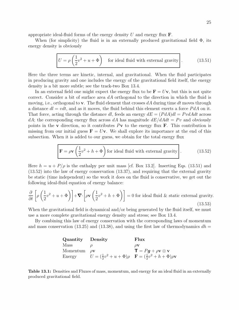
appropriate ideal-fluid forms of the energy density U and energy flux F.When (for simplicity) the fluid is in an externally produced gravitational field &, its
energy density is obviously
U = !
#1
2v2 + u + &
$for ideal fluid with external gravity . (13.51)
Here the three terms are kinetic, internal, and gravitational. When the fluid participatesin producing gravity and one includes the energy of the gravitational field itself, the energydensity is a bit more subtle; see the track-two Box 13.4.
In an external field one might expect the energy flux to be F = Uv, but this is not quitecorrect. Consider a bit of surface area dA orthogonal to the direction in which the fluid ismoving, i.e., orthogonal to v. The fluid element that crosses dA during time dt moves througha distance dl = vdt, and as it moves, the fluid behind this element exerts a force PdA on it.That force, acting through the distance dl, feeds an energy dE = (PdA)dl = PvdAdt acrossdA; the corresponding energy flux across dA has magnitude dE/dAdt = Pv and obviouslypoints in the v direction, so it contributes Pv to the energy flux F. This contribution ismissing from our initial guess F = Uv. We shall explore its importance at the end of thissubsection. When it is added to our guess, we obtain for the total energy flux
F = !v
#1
2v2 + h + &
$for ideal fluid with external gravity . (13.52)
Here h = u + P/! is the enthalpy per unit mass [cf. Box 13.2]. Inserting Eqs. (13.51) and(13.52) into the law of energy conservation (13.37), and requiring that the external gravitybe static (time independent) so the work it does on the fluid is conservative, we get out thefollowing ideal-fluid equation of energy balance:
%
%t
(!
#1
2v2 + u + &
$)+!·
(!v
#1
2v2 + h + &
$)= 0 for ideal fluid & static external gravity.
(13.53)When the gravitational field is dynamical and/or being generated by the fluid itself, we mustuse a more complete gravitational energy density and stress; see Box 13.4.
By combining this law of energy conservation with the corresponding laws of momentumand mass conservation (13.25) and (13.38), and using the first law of thermodynamics dh =
Quantity Density FluxMass ! !vMomentum !v T = Pg + !v * vEnergy U = (1
2v2 + u + &)! F = (1
2v2 + h + &)!v
Table 13.1: Densities and Fluxes of mass, momentum, and energy for an ideal fluid in an externallyproduced gravitational field.

26
Tds+(1/!)dP , we obtain the remarkable result that the entropy per unit mass is conservedmoving with the fluid.
ds
dt= 0 for an ideal fluid . (13.54)
The same conclusion can be obtained when the gravitational field is dynamical and notexternal (cf. Box 13.4 and Ex. 13.13]), so no statement about gravity is included with thisequation. This entropy conservation should not be surprising. If we put no dissipativeprocesses into the energy density or energy flux or stress tensor, then we get no dissipationout. Moreover, the calculation that leads to Eq. (13.54) assures us that, so long as we takefull account of mass and momentum conservation, then the full and sole content of the lawof energy conservation for an ideal fluid is ds/dt = 0.
13.5.7 Joule-Kelvin Method of Cooling a Real Gas
Let us return to the contribution Pv to the energy flux. A good illustration of the impor-tance of this term is provided by the Joule-Kelvin method commonly used to cool gases(Fig. 13.6). In this method, gas is driven from a high-pressure chamber 1 through a nozzleor porous plug into a low-pressure chamber 2, where it can expand and cool. We can analyzethe cooling using energy conservation, with the magnitude of the energy flux at the entranceto the nozzle written as (!1u1 + P1)v1 (where we neglect the kinetic energy and gravita-tional terms as negligible). During a short time $t, the energy that leaves the high-pressurechamber 1 is this energy flux into the nozzle times $t times the nozzle entrance’s area A1 :$E1 = (!1u1 + P1)v1$t A1 = H1; here H1 is the enthalpy that the departing gas “sample”had when it was in chamber 1, occupying the volume v1$t A1. (Without the P1v1 term inthe flux, we would not get this result.) When this gas sample arrives in the low-pressurechamber 2, it is far from statistical (thermodynamic) equilibrium, but it soon equilibrates.After equilibration, it occupies some volume V2, it has done work P2V2 on the gas in chamber2 in order to open up that volume, and it posses an internal energy !2u2V2. Correspondingly,the total energy it has injected into chamber 2 is $E2 = (!2u2 + P2)V2 = H2 (its enthalpy);cf. the last part of Ex. 5.5. Energy conservation, $E1 = $E2, then guarantees that theenthalpy H1 of this gas sample when it was in statistical equilibrium in chamber 1 is thesame as its enthalpy H2 when it has reached statistical equilibrium in chamber 2. Dividing
P1
Nozzle
P2v2
v1
Fig. 13.6: Joule-Kelvin cooling of a gas. Gas flows steadily through a nozzle from a chamber athigh pressure to one at low pressure. The flow proceeds at constant enthalpy. Work done againstattractive intermolecular forces leads to cooling. The e#ciency of cooling can be enhanced byexchanging heat between the two chambers. Gases can also be liquefied in this manner.

27
Box 13.4Self Gravity T2
In the text, we mostly treat the gravitational field as externally imposed and independentof the behavior of the fluid. This is usually a good approximation. However, it isinadequate for discussing the properties of planets and stars. It is easiest to discuss themodifications required by self-gravitational e!ects by amending the conservation laws.
As long as we work within the domain of Newtonian physics, the mass conservationequation (13.25) is una!ected. However, we included the gravitational force per unitvolume !g as a source of momentum in the momentum conservation law (13.38). Itwould fit much more neatly into our formalism if we could express it as the divergenceof a gravitational stress tensor Tg. To see that this is indeed possible, use Poisson’sequation ! · g = !4&G! to write
! · Tg = !!g =(! · g)g
4&G=
! · [g * g ! 12g
2g]
4&G,
so
Tg =g * g ! 1
2g2g
4&G. (1)
Readers familiar with classical electromagnetic theory will notice an obvious and under-standable similarity to the Maxwell stress tensor [Eq. (2.80)] whose divergence equals theLorentz force density.
What of the gravitational momentum density? We expect that this can be relatedto the gravitational energy density using a Lorentz transformation. That is to say itis O(v/c2) times the gravitational energy density, where v is some characteristic speed.However, in the Newtonian approximation, the speed of light, c, is regarded as infiniteand so we should expect the gravitational momentum density to be identically zero inNewtonian theory—and indeed it is. We therefore can write the full equation of motion(13.38), including gravity, as a conservation law
%(!v)
%t+ ! · Ttotal = 0 (2)
where Ttotal includes Tg.
Turn to energy conservation: We have seen in the text that, in a constant, externalgravitational field, the fluid’s total energy density U and flux F are given by Eqs. (13.51)and (13.52). In a general situation, we must add to these some field energy density andflux. On dimensional grounds, these must be Ufield & g2/G and Ffield & &,tg/G (whereg = !!&). The proportionality constants can be deduced by demanding that for anideal fluid in the presence of gravity, the law of energy conservation when combined withmass conservation, momentum conservation, and the first law of thermodynamics, lead

28
Box 13.4, Continued T2to ds/dt = 0 (no dissipation in, so no dissipation out); see Eq. (13.54) and associateddiscussion. The result [Ex. 13.13] is
U = !
#1
2v2 + u + &
$+
g2
8&G, (3)
F = !v
#1
2v2 + h + &
$+
1
4&G
%&
%tg . (4)
Actually, there is an ambiguity in how the gravitational energy is localized. This
ambiguity arises physically from the fact that one can transform away the gravitationalacceleration g, at any point in space, by transforming to a reference frame that falls freelythere. Correspondingly, it turns out, one can transform away the gravitational energydensity at any desired point in space. This possibility is embodied mathematically inthe possibility to add to the energy flux F the time derivative of )&!&/4&G and addto the energy density U minus the divergence of this quantity (where ) is an arbitraryconstant), while preserving energy conservation %U/%t + ! · F = 0. Thus, the followingchoice of energy density and flux is just as good as Eqs. (2) and (3); both satisfy energyconservation:
U = !
#1
2v2 + u + &
$+
g2
8&G!)!·
#&!&
4&G
$= !
(1
2v2 + u + (1 ! ))&
)+(1!2))
g2
8&G,
(5)
F = !v
#1
2v2 + h + &
$+
1
4&G
%&
%tg + )
%
%t
#&!&
4&G
$
= !v
#1
2v2 + h + &
$+ (1 ! ))
1
4&G
%&
%tg +
)
4&G&%g
%t. (6)
[Here we have used the gravitational field equation (2& = 4&G! and g = !!&.] Notethat the choice ) = 1/2 puts all of the energy density into the !& term, while the choice) = 1 puts all of the energy density into the field term g2. In Ex. 13.14 it is shownthat the total gravitational energy of an isolated system is independent of the arbitraryparameter ), as it must be on physical grounds.
A full understanding of the nature and limitations of the concept of gravitationalenergy requires the general theory of relativity (Part VII). The relativistic analog ofthe arbitrariness of Newtonian energy localization is an arbitrariness in the gravitational“stress-energy pseudotensor”.

29
by the mass of the sample, we see that the enthalpy per unit mass, h, is the same in the twochambers: h1 = h2.
Now, the temperature T of the gas, in statistical equilibrium, is some function of enthalpyand pressure, T = T (h, P ); so we can write the temperature drop between chamber 1 andchamber 2 as
$T =
% P2
P1
µJKdP, (13.55)
where µJK ' (%T/%P )h is the so-called Joule-Kelvin coe"cient. A straightforward thermo-dynamic calculation yields the identity
µJK '#%T
%P
$
h
= ! 1
!2cp
#%(!T )
%T
$
P
. (13.56)
The Joule-Kelvin coe"cient of an ideal gas [one with P = nkBT = (!/µmp)kBT ] obvi-ously vanishes. Therefore, the cooling must arise because of the attractive forces (van derWaals forces; Sec. 5.3.2) between the molecules, which are absent in an ideal gas. When areal gas expands, work is done against these forces and the gas therefore cools.
13.6 Incompressible Flows
A common assumption made when discussing the fluid dynamics of highly subsonic flows isthat the density is constant, i.e., that the fluid is incompressible. This is a natural approxi-mation to make when dealing with a liquid like water, which has a very large bulk modulus.It is a bit of a surprise that it is also useful for flows of gases, which are far more compressibleunder static conditions.
To see its validity, suppose that we have a flow in which the characteristic length L overwhich the fluid variables P, !, v etc. vary is related to the characteristic timescale T overwhich they vary by L " vT . In this case, we can compare the magnitude of the variousterms in the Euler equation (13.40) to obtain an estimate of the magnitude of the pressurevariation:
%v
%t*+,-v/T
+ (v · !)v* +, -v2/L
= ! !P
!*+,-%P/"L
! !&*+,-%!/L
. (13.57)
Multiplying through by L and using L/T " v we obtain "P/! % v2+|"&|. Now, the variationin pressure will be related to the variation in density by "P % c2"!, where c =
&(%P/%!)s is
the sound speed (Sec. 16.5), not light speed, and we drop constants of order unity in makingthese estimates. Inserting this into our expression for "P , we obtain the estimate for thefractional density fluctuation
"!
!% v2
c2+"&
c2. (13.58)
Therefore, if the fluid speeds are highly subsonic (v $ c) and the gravitational potential doesnot vary greatly along flow lines, |"&| $ c2, then we can ignore the density variations moving
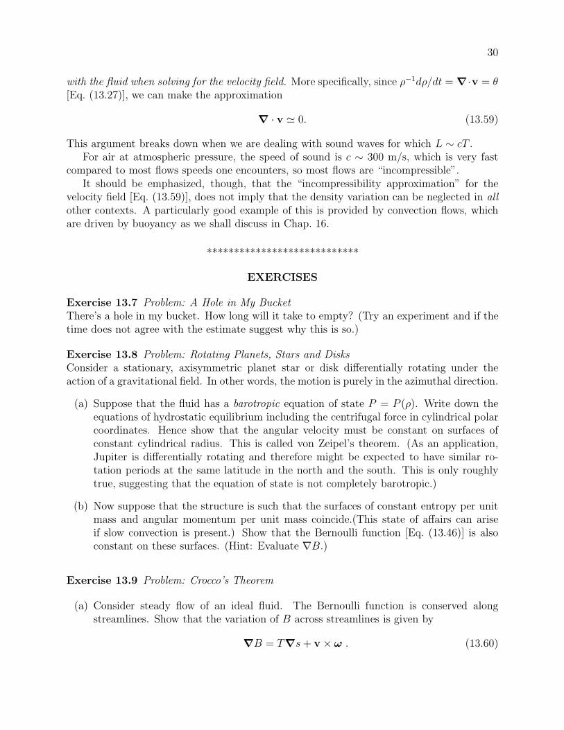
30
with the fluid when solving for the velocity field. More specifically, since !"1d!/dt = !·v = '[Eq. (13.27)], we can make the approximation
! · v # 0. (13.59)
This argument breaks down when we are dealing with sound waves for which L % cT .For air at atmospheric pressure, the speed of sound is c % 300 m/s, which is very fast
compared to most flows speeds one encounters, so most flows are “incompressible”.It should be emphasized, though, that the “incompressibility approximation” for the
velocity field [Eq. (13.59)], does not imply that the density variation can be neglected in allother contexts. A particularly good example of this is provided by convection flows, whichare driven by buoyancy as we shall discuss in Chap. 16.
****************************
EXERCISES
Exercise 13.7 Problem: A Hole in My BucketThere’s a hole in my bucket. How long will it take to empty? (Try an experiment and if thetime does not agree with the estimate suggest why this is so.)
Exercise 13.8 Problem: Rotating Planets, Stars and DisksConsider a stationary, axisymmetric planet star or disk di!erentially rotating under theaction of a gravitational field. In other words, the motion is purely in the azimuthal direction.
(a) Suppose that the fluid has a barotropic equation of state P = P (!). Write down theequations of hydrostatic equilibrium including the centrifugal force in cylindrical polarcoordinates. Hence show that the angular velocity must be constant on surfaces ofconstant cylindrical radius. This is called von Zeipel’s theorem. (As an application,Jupiter is di!erentially rotating and therefore might be expected to have similar ro-tation periods at the same latitude in the north and the south. This is only roughlytrue, suggesting that the equation of state is not completely barotropic.)
(b) Now suppose that the structure is such that the surfaces of constant entropy per unitmass and angular momentum per unit mass coincide.(This state of a!airs can ariseif slow convection is present.) Show that the Bernoulli function [Eq. (13.46)] is alsoconstant on these surfaces. (Hint: Evaluate (B.)
Exercise 13.9 Problem: Crocco’s Theorem
(a) Consider steady flow of an ideal fluid. The Bernoulli function is conserved alongstreamlines. Show that the variation of B across streamlines is given by
!B = T!s + v " " . (13.60)

31
(b) As an example, consider the air in a tornado. In the tornado’s core, the velocityvanishes; and it also vanishes beyond the tornado’s outer edge. Use Crocco’s theoremto show that the pressure in the core is substantially di!erent from that at the outeredge. Is it lower, or is it higher? How does this explain the ability of a tornado tomake the walls of a house explode?
Exercise 13.10 Problem: CavitationA hydrofoil moves with speed V at a depth D = 3m below the surface of a lake; see Figure13.7. Estimate how fast V must be to make the water next to the hydrofoil boil. (Thisboiling, which is called cavitation, results from the pressure P trying to go negative.)
[Note: for a more accurate value of the speed V that triggers cavitation, one would have tocompute the velocity field around the hydrofoil, e.g. using the method of Ex. 14.6 of thenext chapter.]
Exercise 13.11 Example: Collapse of a bubbleSuppose that a spherical bubble has just been created in the water above the hydrofoil inthe previous question. We will analyze its collapse, i.e. the decrease of its radius R(t) fromits value Ro at creation. First show that the assumption of incompressibility implies that theradial velocity of the fluid at any radial location r can be written in the form v = F (t)/r2.Then use the radial component of the Euler equation (13.40) to show that
1
r2
dF
dt+ v%v
%r+
1
!
%P
%r= 0
and integrate this outward from the bubble surface at radius R to infinite radius to obtain
!1
R
dF
dt+
1
2v2(R) =
P0
!
where P0 is the ambient pressure. Hence show that the bubble surface moves with speed
v(R) =
#2P0
3!
$1/2.#
R0
R
$3
! 1
/1/2
V Dhydrofoil
Fig. 13.7: Water flowing past a hydrofoil as seen in the hydrofoil’s rest frame.

32
Suppose that bubbles formed near the pressure minimum on the surface of the hydrofoil areswept back onto a part of the surface where the pressure is much larger. By what factor mustthe bubbles collapse if they are to create stresses which inflict damage on the hydrofoil?
A modification of this solution is also important in interpreting the fascinating phe-nomenon of Sonoluminescence (Brenner, Hilgenfeldt & Lohse 2002). This arises when fluidsare subjected to high frequency acoustic waves which create oscillating bubbles. The tem-peratures inside these bubbles can get so large that the air becomes ionized and radiates.
Exercise 13.12 Derivation: Joule-Kelvin Coe!cientVerify Eq. (13.56)
Exercise 13.13 T2 Derivation: No dissipation “in” means no dissipation “‘out”, andverification of the claimed gravitational energy density and fluxConsider an ideal fluid interacting with a (possibly dynamical) gravitational field that thefluid itself generates via (2& = 4&G!. For this fluid, take the law of energy conservation%U/%t + ! ·F = 0 and from it subtract the scalar product of v with the law of momentumconservation, v · [%(!v)/%t+! ·T)]; then simplify using the law of mass conservation and thefirst law of thermodynamics, to obtain !ds/dt = 0. In your computation, use for U and Fthe expressions given in Eqs. (3) and (4) of Box 13.4. This calculation tells us two things: (i)The law of energy conservation for an ideal fluid reduces simply to conservation of entropymoving with the fluid; we have put no dissipative physics into the fluxes of momentum andenergy, so we get no dissipation out. (ii) The gravitational energy density and flux containedin Eqs. (3) and (4) of Box 13.4 must be correct, since they guarantee that gravity does notalter this “no dissipation in, no dissipation out” result.
Exercise 13.14 T2 Example: Gravitational EnergyIntegrate the energy density U of Eq. (4) of Box 13.4 over the interior and surroundings of anisolated gravitating system to obtain the system’s total energy. Show that the gravitationalcontribution to this total energy (i) is independent of the arbitrariness (parameter )) in theenergy’s localization, and (ii) can be written in the following forms:
Eg =
%dV
1
2!& = ! 1
8&G
%dV g2 =
!G
2
% %dV dV #!(x)!(x#)
|x ! x#| . (13.61)
Interpret each of these expressions physically.
****************************
13.7 Viscous Flows with Heat Conduction
13.7.1 Decomposition of the Velocity Gradient
It is an observational fact that many fluids, when they flow, develop a shear stress (also calleda viscous stress). Honey pouring o! a spoon is a nice example. Most fluids, however, appear

33
to flow quite freely; for example, a cup of tea appears to o!er little resistance to stirringother than the inertia of the water. In such cases, it might be thought that viscous e!ectsonly produce a negligible correction to the flow’s details. However, this is not so. One of themain reasons is that most flows touch solid bodies at whose surfaces the velocity must vanish.This leads to the formation of boundary layers whose thickness and behavior are controlledby viscous forces. The boundary layers in turn can exert a controlling influence on the bulkflow (where the viscosity is negligible); for example, they can trigger the development ofturbulence in the bulk flow — witness the stirred tea cup.
We must therefore augment our equations of fluid dynamics to include viscous stresses.Our formal development proceeds in parallel to that used in elasticity, with the velocity fieldv = d!/dt replacing the displacement field !. As already discussed briefly in Sec. 13.5.4,we decompose the velocity gradient tensor !v into its irreducible tensorial parts: a rate ofexpansion, ', a symmetric, trace-free rate of shear tensor $, and an antisymmetric rate ofrotation tensor r, i.e.
!v =1
3'g + $ + r . (13.62)
Note that we use lower case symbols to distinguish the fluid case from its elastic counterpart:' = d#/dt, $ = d!/dt, r = dR/dt. Proceeding directly in parallel to the treatment in Chap.11, we can invert Eq. (13.62) to obtain
' = ! · v , (13.63a)
*ij =1
2(vi;j + vj;i) !
1
3'gij , (13.63b)
rij =1
2(vi;j ! vj;i) = !1
2+ijk,
k , (13.63c)
where " = 2d#/dt is the vorticity, which is the counterpart of the rotation vector # [Eqs.(11.10)].
13.7.2 Navier-Stokes Equation
Although, as we have emphasized, a fluid at rest does not exert a shear stress, and thisdistinguishes it from an elastic solid, a fluid in motion can resist shear in the velocity field.It has been found experimentally that in most fluids the magnitude of this shear stressis linearly related to the velocity gradient. This law, due to Hooke’s contemporary, IsaacNewton, is the analogue of the linear relation between stress and strain that we used in ourdiscussion of elasticity. Fluids that obey this law are known as Newtonian. (Some examplesof non-Newtonian fluid behavior are shown in Figure 13.8.) In this book, we shall restrictourselves to Newtonian fluids.
Fluids are usually isotropic. (Important exceptions include smectic liquid crystals.) Inthis book we shall restrict ourselves to isotropic fluids, where, by analogy with the theoryof elasticity, we shall describe the linear relation between stress and rate of strain using two

34
Thixotropic
Newtonian ShearStress
Newtonian
ShearStress
Rheopectic Plastic
Time Rate of Strain(a) (b)
Fig. 13.8: Some examples of non-Newtonian behavior in fluids. (a) In a Newtonian fluid theshear stress is proportional to the rate of shear $ and does not vary with time when $ is constant.However, some substances, such as paint, flow more freely with time and are said to be thixotropic.Microscopically, what happens is that the long, thin paint molecules gradually become aligned withthe flow, which reduces their resistance to shear. The opposite behaviour is exhibited by rheopecticsubstances. (b) An alternative type of non-Newtonian behavior is exhibited by various plastics,where a threshold stress is needed before flow will commence.
constants called the coe"cients of bulk and shear viscosity and denoted - and . respectively.We write the viscous contribution to the stress tensor as
Tvis = !-'g ! 2.$ , (13.64)
by analogy to Eq. (11.18).If we include this viscous contribution in the stress tensor, then the law of momentum
conservation %(!v)/%t + ! · T = !g gives the following modification of Euler’s equation(13.40):
!dv
dt= !!P + !g + !(-') + 2( · (.$) (13.65)
This is called the Navier-Stokes equation, and the last two terms are the viscous force density.For incompressible flows (e.g., when the flow is highly subsonic; Sec. 13.6), ' can be ap-
proximated as zero so the bulk viscosity can be ignored. The viscosity coe"cient . generallyvaries in space far more slowly than the shear $, and so can be taken outside the divergence.In this case, Eq. (13.65) simplifies to
dv
dt= !!P
!+ g + /(2v , (13.66)
where
/ ' .!
(13.67)
is known as the kinematic viscosity, by contrast with . which is often called the dynamicviscosity. Equation (13.67) is the commonly quoted form of the Navier-Stokes equation.Values of the kinematic viscosity for common fluids are given in Table 13.2.

35
Quantity Kinematic viscosity / (m2s"1)Water 10"6
Air 10"5
Glycerine 10"3
Blood 3 " 10"6
Table 13.2: Kinematic viscosity for common fluids.
13.7.3 Energy conservation and entropy production
The viscous stress tensor represents an additional momentum flux which can do work on thefluid at a rate Tvis · v per unit area. There is therefore a contribution
Fvis = Tvis · v (13.68)
to the energy flux, just like the term Pv appearing (as part of the !vh) in Eq. (13.52). Di!u-sive heat flow (thermal conductivity) can also contribute to the energy flux; its contributionis [Eq. (3.67b)]
Fcond = !0!T , (13.69)
where 0 is the coe"cient of thermal conductivity. The molecules or particles that produce theviscosity and the heat flow also carry energy, but their energy density is included already in u,the total internal energy per unit mass. The total energy flux, including these contributions,is shown in Table 13.3, along with the energy density and the density and flux of momentum.
We see most clearly the influence of the dissipative viscous forces and heat conductionon energy conservation by inserting the energy density and flux from Table 13.3 into thelaw of energy conservation %U/%t + ! · F = 0, subtracting v · [%(!v)/%t + ! · T = 0] (vdotted into momentum conservation), and simplifying using mass conservation and the firstlaw of thermodynamics. The result (Ex. 13.17) is the following equation for the evolution ofentropy:
T
(!
#ds
dt
$+ ! ·
#Fcond
T
$)= -'2 + 2.$ : $ +
0
T(!T )2 . (13.70)
The term in square brackets on the left side represents an increase of entropy per unit volumemoving with the fluid due to dissipation (the total increase minus that due to heat flowingconductively into a unit volume); multiplied by T this is the dissipative increase in entropy
Quantity Density FluxMass ! !v
Momentum !v T = !v * v + Pg + g2
4&G ! -'g ! 2.$Energy U = (1
2v2 + u + &)! F = (1
2v2 + h + &)!v ! -'v ! 2.$ · v ! 0!T
Table 13.3: Densities and Fluxes of mass, momentum, and energy for a dissipative fluid in anexternally produced gravitational field. For self-gravitating systems see Box 13.4.

36
density. This increase of random, thermal energy is being produced, on the right side, byviscous heating (first two terms), and by the flow of heat Fcond = !0!T down a temperaturegradient !!T (third term).
The dissipation equation (13.70) is the full content of the law of energy conservation fora dissipative fluid, when one takes account of mass conservation, momentum conservation,and the first law of thermodynamics.
Remarkably, we can combine this Lagrangian rate of viscous dissipation with the equationof mass conservation (13.25) to obtain an Eulerian di!erential equation for the entropyincrease:
%(!s)
%t+ ! · (!sv ! 0! ln T ) =
1
T
0-'2 + 2.$ : $ +
0
T(!T )2
1. (13.71)
The left hand side of this equation describes the rate of change of entropy density plus thedivergence of entropy flux. The right hand side is therefore the rate of production of entropyper unit volume. Invoking the second law of thermodynamics, this must be positive definite.Therefore the two coe"cients of viscosity, like the bulk and shear moduli, must be positive,as must the coe"cient of thermal conductivity 0 (heat must flow from hotter regions tocooler regions).
In most laboratory and geophysical flows, thermal conductivity is unimportant, so weshall largely ignore it until Chap. 16.
13.7.4 Molecular Origin of Viscosity
Microscopically, we can distinguish gases from liquids. In gases, molecules of mass m travel adistance of order their mean free path 1 before they collide. If there is a velocity gradient, !vin the fluid, then they will, on average, transport a momentum % m1!v with themselves.If there are n molecules per unit volume traveling with mean speeds c, then the extramomentum crossing a unit area in unit time is % nmc1!v, from which we may extract anestimate of the coe"cient of shear stress
. =1
3!c1 . (13.72)
Here the numerical coe"cient of 1/3 has been inserted to agree with a proper kinetic-theorycalculation. (Since, in the language of Chap. 3, the viscosity coe"cients are actually “trans-port coe"cients” for momentum, a kinetic-theory calculation can be made using the tech-niques of Section 3.7.) Note from Eq. (13.72) that in a gas, where the mean thermal energyis % mc2 % kBT , the coe"cient of viscosity will increase with temperature, / & T 1/2.
In a liquid, where the molecules are less mobile, it is the close intermolecular attractionthat produces the shear stress. The ability of molecules to slide past one another thereforeincreases rapidly with their thermal activation, causing typical liquid viscosity coe"cientsto fall dramatically with temperature.

37
13.7.5 Reynolds’ Number
The kinematic viscosity / has dimensions [L]2[T ]"1. This suggests that we quantify theimportance of viscosity by comparing / with the product of a characteristic flow velocity Vand a characteristic length L. The dimensionless combination
R =LV
/(13.73)
is known as the Reynolds’ number, and is the first of many dimensionless numbers we shallencounter in our study of fluid mechanics. Flows with Reynolds number much less than unity– such as the tragic Boston molasses tank explosion in 1919 – are dominated by viscosity.Large Reynolds’ number flows can also be controlled by viscosity (as we shall see in laterchapters), especially when the viscosity acts near boundaries, despite the fact that the viscousstresses are negligible over most of the flow’s volume.
13.7.6 Pipe Flow
Let us now consider a simple example of viscous stresses at work, namely the flow of blooddown an artery. We shall model the artery as a cylindrical pipe of radius R, down which theblood is forced by a pressure gradient. This is an example of what is called pipe flow.
Because gravity is unimportant and the flow is time independent, the law of momentumconservation %(!v)/%t + ! ·T = !g [Eq. (13.38)] reduces to the vanishing divergence of thetotal stress tensor:
! · (!v * v + Pg ! 2.$) = 0 (13.74)
[Eq. (13.39) augmented by the shear viscous stress (13.64)]. Now, in most instances of pipeflow, including blood in an artery, !v2 $ $P = (the pressure di!erence between the pipe’stwo ends), so we can neglect the first term in Eq. (13.74). We assume that the flow islaminar (smooth, as is usually the case for blood in arteries — fortunately!), so v pointssolely along the z direction and is only a function of cylindrical radius 2. This is, in fact,a very important restriction. As we shall discuss in detail in Chap. 15, it often fails (e.g. incrude oil pipelines) because the flow becomes turbulent, and this has a major impact.
As the density is e!ectively constant (this flow is very subsonic with negligible gravity),and mass is conserved, the velocity cannot change along the pipe, whence v = v(2)ez.Therefore the only non-vanishing component of the shear tensor is the 2z component. Re-expressing Eq. (13.74) in cylindrical coordinates, and inferring from it that the pressure is afunction of z only and not of 2, we obtain
1
2
d
d2
#2.
dv
d2
$=
dP
dz, (13.75)
where dP/dz is the pressure gradient along the pipe. This di!erential equation must besolved subject to the boundary conditions that the velocity gradient vanish at the center ofthe pipe and that the velocity vanish at its walls. The solution is
v(2) = !dP
dz
R2 !22
4.(13.76)
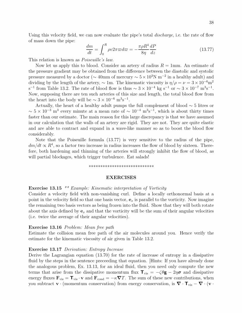
38
Using this velocity field, we can now evaluate the pipe’s total discharge, i.e. the rate of flowof mass down the pipe:
dm
dt=
% R
0
!v2&2d2 = !&!R4
8.
dP
dz(13.77)
This relation is known as Poiseuille’s law.Now let us apply this to blood. Consider an artery of radius R = 1mm. An estimate of
the pressure gradient may be obtained from the di!erence between the diastolic and systolicpressure measured by a doctor (% 40mm of mercury % 5"103N m"2 in a healthy adult) anddividing by the length of the artery, % 1m. The kinematic viscosity is ./! = / = 3"10"6m2
s"1 from Table 13.2. The rate of blood flow is thus % 3 " 10"4 kg s"1 or % 3 " 10"7 m3s"1.Now, supposing there are ten such arteries of this size and length, the total blood flow fromthe heart into the body will be % 3 " 10"6 m3s"1.
Actually, the heart of a healthy adult pumps the full complement of blood % 5 litres or% 5 " 10"3 m3 every minute at a mean rate of % 10"4 m3s"1, which is about thirty timesfaster than our estimate. The main reason for this large discrepancy is that we have assumedin our calculation that the walls of an artery are rigid. They are not. They are quite elasticand are able to contract and expand in a wave-like manner so as to boost the blood flowconsiderably.
Note that the Poiseuille formula (13.77) is very sensitive to the radius of the pipe,dm/dt & R4, so a factor two increase in radius increases the flow of blood by sixteen. There-fore, both hardening and thinning of the arteries will strongly inhibit the flow of blood, aswill partial blockages, which trigger turbulence. Eat salads!
****************************
EXERCISES
Exercise 13.15 ** Example: Kinematic interpretation of VorticityConsider a velocity field with non-vanishing curl. Define a locally orthonormal basis at apoint in the velocity field so that one basis vector, ex is parallel to the vorticity. Now imaginethe remaining two basis vectors as being frozen into the fluid. Show that they will both rotateabout the axis defined by ex and that the vorticity will be the sum of their angular velocities(i.e. twice the average of their angular velocities).
Exercise 13.16 Problem: Mean free pathEstimate the collision mean free path of the air molecules around you. Hence verify theestimate for the kinematic viscosity of air given in Table 13.2.
Exercise 13.17 Derivation: Entropy IncreaseDerive the Lagrangian equation (13.70) for the rate of increase of entropy in a dissipativefluid by the steps in the sentence preceeding that equation. [Hints: If you have already donethe analogous problem, Ex. 13.13, for an ideal fluid, then you need only compute the newterms that arise from the dissipative momentum flux Tvis = !-'g ! 2.$ and dissipativeenergy fluxes Fvis = Tvis · v and Fcond = !0!T . The sum of these new contributions, whenyou subtract v · (momentum conservation) from energy conservation, is ! · Tvis ! ! · (v ·

39
Tvis) ! ! · Fcond; and this must be added to the left side of the result !Tds/dt = 0, Eq.(13.54), for an ideal fluid.]
****************************
13.8 T2 Relativistic Dynamics of an Ideal Fluid
When a fluid’s speed v = |v| becomes comparable to the speed of light c = 1, or P/! or ubecome of order unity, Newtonian fluid mechanics breaks down and must be replaced by arelativistic treatment. In this section, we shall briefly sketch the resulting laws of relativisticfluid dynamics for an ideal (perfect) fluid. For the extension to a fluid with dissipation(viscosity and heat conductivity), see, e.g., Ex. 22.7 of Misner, Thorne and Wheeler (1973).
Our treatment takes o! from the brief description of an ideal, relativistic fluid in Secs.2.12.3 and 2.13.3 of Chap. 2.
13.8.1 T2 Stress-Energy Tensor and Equations of RelativisticFluid Mechanics
For relativistic fluids, we use ! to denote the total density of mass-energy (including restmass and internal energy), in the fluid’s local rest frame; it is sometimes written as
! = !o(1 + u) , where !o = mBn (13.78)
is the density of rest mass, mB is some standard mean rest mass per baryon, n is the numberdensity of baryons, !o is the density of rest mass, and u is the specific internal energy (Sec.2.12.3 of Chap. 2).
The stress-energy tensor T $' for a relativistic, ideal fluid takes the form [Eq. (2.74b)]
T $' = (!+ P )u$u' + Pg$' , (13.79)
where P is the fluid’s pressure (as measured in its local rest frame), u$ is its 4-velocity, andg$' is the spacetime metric. In the fluid’s local rest frame, where u0 = 1 and uj = 0, thecomponents of this stress-energy tensor are, of course, T 00 = !, T j0 = T 0j = 0, T jk = Pgjk =P "jk.
The dynamics of our relativistic, ideal fluid are governed by five equations: First Equa-tion: the law of rest-mass conservation, (!ou$);$ = 0, can be rewritten in the forms [Eqs.(2.64) and (2.65) of Ex. 2.24]
d!o
d#= !!o
3( · 3u , i.e.d(!oV )
d#= 0 , (13.80a)
where d/d# = 3u · 3( is the derivative with respect to proper time moving with the fluid,3( · 3u = (1/V )(dV/d#) is the divergence of the fluid’s 4-velocity, and V is the volume of afluid element. Second and Third Equations: Energy conservation, in the form of the vanishing

40
divergence of the stress-energy tensor projected onto the fluid 4-velocity, u$T $';' = 0, when
combined with the law of mass conservation, reduces to the first law of thermodynamicswithout dissipation [Eq. (2.76b)] because our fluid is dissipation-free:
d!
d#= !(!+ P )3( · 3u , i.e.
d(!V )
d#= !P
dV
d#, whence,
ds
d#= 0 . (13.80b)
Here s is the entropy per unit rest mass. There are actually two equations here: the constancyof s moving with the fluid, and the evolution equation for !. Fourth Equation: Momentumconservation, obtained by projecting the vanishing divergence of the stress-energy tensororthogonal to the fluid’s 4-velocity, P$µT µ(
;( = 0, reduces to [Eq. (2.76c)]
(!+ P )du$
d#= !P $µP;µ = 0 , where P $µ = g$µ + u$uµ . (13.80c)
This is the relativistic Euler equation, and P $µ (not to be confused with the fluid pressure Por its gradient P;µ) is the tensor that projects orthogonal to 3u. Note that the inertial massper unit volume is !+ P (Ex. 2.27), and that the pressure gradient produces a force that isorthogonal to 3u. Fifth Equation: An equation of state must be provided, e.g. in the form
P = P (!o, s) . (13.80d)
Equations (13.80) are four independent scalar equations and one vector equation for thefour scalars !o, !, P, s and one vector 3u.
As an example of an equation of state, one that we shall use below, consider a fluid sohot that its pressure and energy density are dominated by thermal motions of relativisticparticles (photons, electron-positron pairs, ...), so P = !/3 [Eq. (3.51a)]. Then from thefirst law of thermodynamics for a fluid element d(!V ) = !PdV and the law of rest-massconservation d(!oV ) = 0, one can deduce the relativistic polytropic equation of state
P =1
3! = K(s)!4/3
o . (13.81)
13.8.2 T2 Relativistic Bernoulli Equation and UltrarelativisticAstrophysical Jets
When the relativistic flow is steady (independent of time t in some chosen inertial frame),the law of energy conservation in that frame, T 0µ
;µ = 0 and the law of mass conservation,(!ouµ);µ = 0 together imply that a certain relativistic Bernoulli function B is conserved alongflow lines, specifically:
dB
d#= $vj
%B
%xj= 0 , where B =
(!+ P )$
!o. (13.82)
Here $ = u0 = 1/+
1 ! v2. A direct proof is left as an exercise for the reader, Ex. 13.18.The following more indirect, geometric proof provides useful insight:
Consider a narrow tube in space, whose walls are generated by streamlines (i.e., aretangent to the velocity field v); Fig. 13.9. Denote the tube’s interior by V and its boundary

41
A1
A2
v
Fig. 13.9: A tube generated by streamlines for a stationary flow. The tube ends are orthogonalto the streamlines and have areas A1 and A2.
by %V. Because the flow is steady, the law of mass conservation (!ou$);$ = 0 reduces tothe vanishing spatial divergence (!ouj);j = (!o$vj);j = 0. Integrate this equation over thetube’s interior and apply Gauss’s law to obtain
'#V !o$vjd'j = 0. Because the walls of the
tube are parallel to vj, they give zero contribution. The contribution from the ends give(!o$v)2A2! (!o$v)1A1 = 0. In other words: The product 'o(vA is constant along thestream tube.
Similarly, for our steady flow, the law of energy conservation T 0$;$ = 0 reduces to the
vanishing spatial divergence T 0j;j = [(! + P )$2vj];j = 0, which, when integrated over the
tube’s interior and converted to a surface integral using Gauss’s theorem, implies that: Theproduct (' + P )(2vA is constant along the stream tube.
The ratio of these two constants, (!+P )$/!o = B must also be constant along the narrowtube, or (since B is independent of the tube area), it must be constant along a streamline,which is Bernoulli’s theorem.
An important venue for relativistic fluid mechanics is the narrow relativistic jets thatemerge from some galactic nuclei. The flow velocities in some of these jets are measured tobe so close to the speed of light, that $ , 1. Assuming the gas pressure P and mass-energydensity ! are dominated by relativistic particles, so the equation of state is P = !/3 = K!4/3
o ,we can use the above bold-faced conservation laws to learn how !, P , and $ evolve alongsuch a jet:
From the relativistic Bernoulli theorem (the ratio of the two constants) and the equation
of state, we deduce that $ & B!o/(! + P ) & !o/!4/3o & !"1/3
o & !"1/4. This describesa conversion of the jet’s internal mass-energy (% !) into bulk flow energy (% $): As theinternal energy (the energy of random thermal motions of the jet’s particles) goes down, thebulk flow energy (energy of organized flow) goes up.
This energy exchange is actually driven by changes in the jet’s cross sectional area, which(in some jets) is controlled by competition between the inward pressure of surrounding, little-moving gas and outward pressure from the jet itself. Since !o$vA # !o$A is constant alongthe jet, we have A & 1/(!o$) & $2 & !"1/2. Therefore, as the jet’s cross sectional area Aincreases, internal energy ! & 1/A2 goes down and the energy of bulk flow, $ & A1/2 goesup. When $ drops to near unity, this transformation of internal energy into bulk-flow energydies out.
How the jet can get started in the first place we shall explore in Chaps. 17 and 25.

42
13.8.3 T2 Nonrelativistic Limit of the Stress-Energy Tensor
It is instructive to evaluate the nonrelativistic limit of the perfect-fluid stress-energy tensorT $' = (! + P )u$u' + Pg$', and verify that it has the form we deduced in our study ofnonrelativistic fluid mechanics: Table 13.1 on page 25 with vanishing gravitational potential& = 0.
In the nonrelativistic limit, the fluid is nearly at rest in the chosen Lorentz referenceframe. It moves with ordinary velocity v = dx/dt that is small compared to the speed oflight, so the temporal part of its 4-velocity u0 = 1/
+1 ! v2 and spatial part u = u0v can be
approximated as
u0 # 1 +1
2v2 , u #
#1 +
1
2v2
$v . (13.83)
We shall write ! = !o(1+u) [Eq. (13.78)], where u is the specific internal energy (not to beconfused with the fluid 4-velocity 3u or its spatial part u). Now, in our chosen Lorentz framethe volume of each fluid element is Lorentz contracted by the factor
+1 ! v2 and therefore the
rest mass density is increased from !o to !o/+
1 ! v2 = !ou0; and correspondingly the rest-mass flux is !ou0v = !ou [Eq. 2.62)], and the law of rest-mass conservation is %(!ou0)/%t +%(!ouj)/%xj = 0. When taking the Newtonian limit, we should identify the Newtonian mass!N with the low-velocity limit of this rest-mass density:
!N = !ou0 # !o
#1 +
1
2v2
$. (13.84)
The nonrelativistic limit regards the specific internal energy u, the kinetic energy per unitmass 1
2v2, and the ratio of pressure to rest-mass density P/!o as of the same order of smallness
u % 1
2v2 % P
!o$ 1 , (13.85)
and it expresses the momentum density T j0 accurate to first order in v ' |v|, the momentumflux (stress) T jk accurate to second order in v, the energy density T 00 accurate to secondorder in v, and the energy flux T 0j accurate to third order in v. To these accuracies, theperfect-fluid stress-energy tensor (13.79) takes the following form:
T j0 = !Nvj , T jk = Pgjk + !Nvjvk ,
T 00 = !N +1
2!Nv2 + !Nu , T 0j = !Nvj +
#1
2v2 + u +
P
!N
$!Nvj ; (13.86)
see Ex. 13.19(c). These are precisely the same as the nonrelativistic momentum density,momentum flux, energy density, and energy flux in Table 13.1, aside from the notationalchange from there to here !) !N , and aside from including the rest mass-energy !N = !Nc2
in T00 here but not there, and including the rest-mass-energy flux !Nvj in T 0j here but notthere.
****************************
EXERCISES

43
Exercise 13.18 T2 Derivation: Relativistic Bernoulli Theorem
By manipulating the di!erential forms of the law of rest-mass conservation and the law ofenergy conservation, derive the constancy of B = (!+ P )$/!o along flow lines, Eq. (13.82).
Exercise 13.19 T2 Derivation: Nonrelativistic Limit of Perfect-Fluid Stress-Energy Ten-sor
(a) Show that in the nonrelativistic limit, the components of the perfect-fluid stress-energytensor (13.79) take on the forms (13.86), and verify that these agree with the densitiesand fluxes of energy and momentum that are used in nonrelativistic fluid mechanics(Table 13.1 on page 25).
(b) Show that it is the contribution of the pressure P to the relativistic density of inertialmass that causes the term (P/!N)!Nv = Pv to appear in the nonrelativistic energyflux.
****************************
Bibliographic Note
There are many good texts on fluid mechanics, most directed toward an engineering orapplied mathematics audience. Among those we find useful are Acheson (1990) at an ele-mentary level, and Batchelor (1970) and Lighthill (1986) at a more advanced level. Landauand Lifshitz (1959) as always is terse, but good for physicists who already have some knowl-edge of the subject. Tritton (1977) takes an especially physical approach to the subject,with lots of useful diagrams and photographs of fluid flows.
Physical intuition is very important in fluid mechanics, and is best developed with the aidof visualizations — both movies and photographs. In recent years many visualizations havebeen made available on the web. For a catalog, see University of Iowa Fluids Laboratory(1999). Movies that we have found especially useful are those of Hunter Rouse (1965) andthe National Committee for Fluid Mechanics Films (1963).
Bibliography
Acheson, D. J. 1990. Elementary Fluid Dynamics, Oxford: Clarendon Press.
Batchelor, G. K. 1970. An Introduction to Fluid Dynamics, Cambridge: CambridgeUniversity Press.
Brenner, M. P., Hilgenfeldt, S. & Lohse, D. 2002 Rev. Mod. Phys. 74 425
Chandrasekhar, S. 1939. Stellar Structure, Chicago: University of Chicago Press;reprinted by Dover Publications.

44
Landau, L. D. and Lifshitz, E. M. 1959. Fluid Mechanics, Oxford: Pergamon.
Lighthill, J. 1986. An Informal Introduction to Theoretical Fluid Mechanics, Oxford:Oxford University Press.
Misner, C.W., Thorne, K.S., and Wheeler, J.A. 1973. Gravitation, San Francisco:Freeman.
National Committee for Fluid Mechanics Films, ca. 1963. Fluid Mechanics Films.Available at http://web.mit.edu/fluids/www/Shapiro/ncfmf.html .
Reif, F. 1959. Fundamentals of Statistical and Thermal Physics, New York: McGraw-Hill.
Rouse, H. ca. 1965. Fluid Mechanics Movies. Available athttp://users.rowan.edu/%orlins/fm/movies.html .
Tritton, D. J. 1977. Physical Fluid Dynamics, Wokingham: van Nostrand-Reinhold.
University of Iowa Fluids Laboratory. 1999. Flow Visualization & Simulation Gallery,http://css.engineering.uiowa.edu/fluidslab/referenc/visualizations.html .
White, F. M. 1974. Viscous Fluid Flow, New York: McGraw-Hill.

45
Box 13.5Terminology in Chapter 13
This chapter introduces a large amount of terminology. We list much of it here.
adiabatic A process in which each fluid element conserves its entropy.
adiabatic index The parameter % that relates pressure and density changes "P/P =%"!/! in an adiabatic process. For an ideal gas, it is the ratio of specific heats,% = $ ' CP/CV .
advective time derivative The time derivative d/dt = %/%t + v · ! moving with thefluid. Also called the convective time derivative.
barotropic A process or equation in which pressure can be regarded as a function solelyof density, P = P (!).
Bernoulli function, also sometimes called Bernoulli constant. B = !(12v
2 + h + &).
bulk viscosity, coe$cient of The proportionality constant - relating rate of expan-sion to viscous stress, Tvis = !-'g.
convective time derivative Same as advective time derivative.
dissipation A process that increases the entropy. Viscosity and di!usive heat flow (heatconduction) are forms of dissipation.
equation of state In this chapter, where chemical and nuclear reactions do not occur:relations of the form u(!, s), P (!, s) or u(!, T ), P (!, T ).
Eulerian changes Changes in a quantity at fixed location in space; cf. Lagrangianchanges.
Euler equation Newton’s “F = ma” equation for an ideal fluid, !dv/dt = !!P + !g.
expansion, rate of Fractional rate of increase of a fluid element’s volume, ' = ! · v.
gas A fluid in which the separations between molecules are large compared to the molec-ular sizes and there are no long-range forces between molecules except gravity;contrast this with a liquid.
ideal gas (also called “perfect gas”) A gas in which the sizes of the molecules and(nongravitational) forces between them are completely neglected, so the pressureis due solely to kinetic motions of molecules, P = nkBT = (!/µmp)kBT .
ideal flow A flow in which there is no dissipation.
ideal fluid (also called “perfect fluid”) A fluid in which there are no dissipative pro-cesses.
incompressible A process or fluid in which the fractional changes of density are small,"!/!$ 1, so the velocity can be approximated as divergence free, ! · v = 0.
inviscid With negligible viscosity.
irrotational A flow or fluid with vanishing vorticity.
isentropic A process or fluid in which the entropy per unit rest mass s is the sameeverywhere.

46
Box 13.5, Continued
isothermal A process or fluid in which the temperature is the same everywhere.
isobar A surface of constant pressure.
kinematic viscosity / ' ./!, the ratio of the coe"cient of shear viscosity to the den-sity.
Lagrangian changes Changes measured moving with the fluid; cf. Eulerian changes.
laminar flow A non-turbulent flow.
liquid A fluid such as water in which the molecules are packed side by side; contrastthis with a gas.
mean molecular weight µ The average mass of a molecule in a gas, divided by themass of a proton.
Navier-Stokes equation Newton’s “F = ma” equation for a viscuous, incompressiblefluid, dv/dt = !(1/!)!P + /(2v + g.
Newtonian fluid Two meanings: (i) nonrelativistic fluid; (ii) a fluid in which the shearstress tensor is proportional to the rate of shear $ and is time-independent when$ is constant.
perfect gas Ideal gas.
perfect fluid Ideal fluid.
polytropic A barotropic pressure-density relation of the form P & !1+1/n for some con-stant n called the polytopic index. The proportionality constant is often a functionof entropy.
Reynolds’ number The ratio R = LV//, where L is the characteristic lengthscale ofa flow, V is the characteristic velocity, and / is the kinematic viscosity. In order ofmagnitude this is the ratio of inertial acceleration (v · !)v to viscous acceleration/(2v in the Navier-Stokes equation.
rotation, rate of Antisymmetric part of the gradient of velocity; vorticity convertedinto an antisymmetric tensor using the Levi-Civita tensor.
shear, rate of Symmetric, trace-free part of the gradient of velocity, $.
steady flow One that is independent of time in some chosen reference frame.
turbulent flow A flow characterized by chaotic fluid motions.
vorticity The curl of the velocity field, ".

47
Box 13.6Important Concepts in Chapter 13
• Dependance of pressure on density: equation of state; "P = K"!/! for liquid;"P/P = %"!/! for gas, Sec. 13.2
• Hydrostatic equilibrium, Sec. 13.3
• Archimedes law, Sec. 13.3.1
• Shapes of rotating bodies, Sec. 13.3.2
• Centrifugal potential and hydrostatics in rotating reference frame, Sec. 13.3.3
• Conservation laws: mass, momentum and energy; Lagrangian vs. Eulerian ap-proach, Sec. 13.4
• Gravitational field: densities and fluxes of momentum and energy, Box 13.4
• Viscous stress and energy flux, Sec. 13.7.2
• Thermal conductivity and di!usive energy flux, Sec. 13.7.2
• Densities and fluxes of mass, momentum, and energy summarized, Tables 13.1 and13.3
• Euler equation (momentum conservation) for an ideal fluid, Secs. 13.5.2, 13.5.3
• Bernoulli’s theorem, Newtonian — Sec. 13.5.4, relativistic — Sec. 13.8.2
• Incompressibility of subsonic gas, Sec. 13.6
• Rates of expansion, rotation, and shear, and vorticity, Secs. 13.5.4 and 13.7.1
• Navier-Stokes equation (momentum conservation) for viscous, incompressible fluid,Sec. 13.7.2
• Energy conservation equivalent to a law for evolution for entropy, Secs. 13.5.6,13.7.3
• Entropy increase (dissipation) due to viscosity and di!usive heat flow, Sec. 13.7.3
• Molecular origin of viscosity, Sec. 13.7.4