The landing gear system in multi-machine Hybrid Event-B · The landing gear system in multi-machine...
24
Int J Softw Tools Technol Transfer (2017) 19:205–228 DOI 10.1007/s10009-015-0409-7 ABZ 2014 The landing gear system in multi-machine Hybrid Event-B Richard Banach 1 Published online: 18 December 2015 © The Author(s) 2015. This article is published with open access at Springerlink.com Abstract A system development case study problem based on a set of aircraft landing gear is examined in Hybrid Event-B (an extension of Event-B that includes provision for continuously varying behaviour as well as the usual discrete changes of state). Although tool support for Hybrid Event-B is currently lacking, the complexity of the case study pro- vides a valuable challenge for the expressivity and modelling capabilities of the Hybrid Event-B formalism. The size of the case study, and in particular, the number of overtly indepen- dent subcomponents that the problem domain contains, both significantly exercise the multi-machine and coordination capabilities of the modelling formalism. These aspects of the case study, vital in the development of realistic cyberphysical systems in general, have contributed significant improve- ments in the theoretical formulation of multi-machine Hybrid Event-B itself. Keywords Hybrid Event-B · Landing gear case study · Refinement · Multicomponent systems 1 Introduction This paper reports on a treatment of a landing gear system case study (see [17]) using Hybrid Event-B. Hybrid Event-B [9, 10] is an extension of the well-known Event-B frame- work, in which continuously varying state evolution, along with the usual discrete changes of state, is admitted. Since air- craft systems are replete with interactions between physical law and the engineering artefacts that are intended to ensure B Richard Banach [email protected] 1 School of Computer Science, University of Manchester, Oxford Road, Manchester M13 9PL, UK appropriate aircraft behaviour, they are prime examples of cyberphysical systems [15, 19, 26, 31], especially when one takes into account the increasing use of remote monitoring of such systems via global communication networks. As such, there is a prima facie case for attempting the landing gear problem using Hybrid Event-B. In the case of landing gear systems specifically, a good idea of the real complexity of such systems can be gained from Chapter 13 of [33]. Given that landing gear is predominantly controlled by hydraulic systems (see Chapter 12 of [33]), it might be imag- ined that the requirements for the present case study [17], would feature relevant physical properties quite extensively. Of course Hybrid Event-B would be ideally suited to model and quantify the interactions between these physical proper- ties and the control system—for example, on the basis of the theoretical models and practical heuristics detailed in references such as [1, 22, 25]. However, it is clear that the requirements in [17] have been heavily slanted to remove such aspects almost completely, presumably because the overwhelming majority of tools in the verification field would not be capable of addressing the requisite continuous aspects. Instead, the relevant properties are reduced to constants (per- haps accompanied by margins of variability) that delimit the duration of various physical processes. This perspective is appropriate to a treatment centred on system control via iso- lated discrete events, such events being used to mark the start and end of a physical process while quietly ignoring what might happen in the interior. While this approach cer- tainly reduces the modelling workload, the penalty paid for it is the loss of the ability to justify the values of these con- stants during the verification activity, whether this be on the basis of deeper theory or of values obtained from lower level phenomenological models. Despite this reservation, a small number of simple con- tinuous behaviours are left within the requirements in [17]. 123
Transcript of The landing gear system in multi-machine Hybrid Event-B · The landing gear system in multi-machine...

Int J Softw Tools Technol Transfer (2017) 19:205–228DOI 10.1007/s10009-015-0409-7
ABZ 2014
The landing gear system in multi-machine Hybrid Event-B
Richard Banach1
Published online: 18 December 2015© The Author(s) 2015. This article is published with open access at Springerlink.com
Abstract A system development case study problem basedon a set of aircraft landing gear is examined in HybridEvent-B (an extension of Event-B that includes provision forcontinuously varying behaviour as well as the usual discretechanges of state). Although tool support for Hybrid Event-Bis currently lacking, the complexity of the case study pro-vides a valuable challenge for the expressivity and modellingcapabilities of the Hybrid Event-B formalism. The size of thecase study, and in particular, the number of overtly indepen-dent subcomponents that the problem domain contains, bothsignificantly exercise the multi-machine and coordinationcapabilities of the modelling formalism. These aspects of thecase study, vital in the development of realistic cyberphysicalsystems in general, have contributed significant improve-ments in the theoretical formulation of multi-machine HybridEvent-B itself.
Keywords Hybrid Event-B · Landing gear case study ·Refinement · Multicomponent systems
1 Introduction
This paper reports on a treatment of a landing gear systemcase study (see [17]) using Hybrid Event-B. Hybrid Event-B[9,10] is an extension of the well-known Event-B frame-work, in which continuously varying state evolution, alongwith the usual discrete changes of state, is admitted. Since air-craft systems are replete with interactions between physicallaw and the engineering artefacts that are intended to ensure
B Richard [email protected]
1 School of Computer Science, University of Manchester,Oxford Road, Manchester M13 9PL, UK
appropriate aircraft behaviour, they are prime examples ofcyberphysical systems [15,19,26,31], especially when onetakes into account the increasing use of remote monitoring ofsuch systems via global communication networks. As such,there is a prima facie case for attempting the landing gearproblem using Hybrid Event-B. In the case of landing gearsystems specifically, a good idea of the real complexity ofsuch systems can be gained from Chapter 13 of [33].
Given that landing gear is predominantly controlled byhydraulic systems (see Chapter 12 of [33]), it might be imag-ined that the requirements for the present case study [17],would feature relevant physical properties quite extensively.Of course Hybrid Event-B would be ideally suited to modeland quantify the interactions between these physical proper-ties and the control system—for example, on the basis ofthe theoretical models and practical heuristics detailed inreferences such as [1,22,25]. However, it is clear that therequirements in [17] have been heavily slanted to removesuch aspects almost completely, presumably because theoverwhelming majority of tools in the verification field wouldnot be capable of addressing the requisite continuous aspects.Instead, the relevant properties are reduced to constants (per-haps accompanied by margins of variability) that delimit theduration of various physical processes. This perspective isappropriate to a treatment centred on system control via iso-lated discrete events, such events being used to mark thestart and end of a physical process while quietly ignoringwhat might happen in the interior. While this approach cer-tainly reduces the modelling workload, the penalty paid forit is the loss of the ability to justify the values of these con-stants during the verification activity, whether this be on thebasis of deeper theory or of values obtained from lower levelphenomenological models.
Despite this reservation, a small number of simple con-tinuous behaviours are left within the requirements in [17].
123
206 R. Banach
These are confined to simple linear behaviours of some partsof the physical apparatus. Although they are very simple,these linear behaviours are nevertheless enough to demon-strate many of the essential capabilities of the Hybrid Event-Bformalism in dealing with continuous phenomena and theirinteraction with discrete events.
Besides the continuous behaviours that need to beaddressed by any comprehensive formalism for cyberphysi-cal systems, there are the issues of structure and architecture.Genuine cyberphysical systems are invariably composed ofa(n often large) number of components, each with somedegree of autonomy—while they nevertheless remain cou-pled to, and interact with, each other. The multi-machineversion of Hybrid Event-B is intended to confront the chal-lenges that this raises. Fortunately, the landing gear case study[17] is rich enough in structure to adequately exercise theseaspects of the formalism.
The rest of this paper is as follows. Section 2 overviewsthe landing gear system, emphasising those elements thatare of most interest to our development. Section 3 then givesa summary of single machine Hybrid Event-B. Section 4extends this to cover multiple machines. The issues exploredhere lead to the hypergraph structured system architecturesdiscussed in Sect. 5.
Section 6 then gives an architectural overview of thesubsequent development, relating the general discussion ofSect. 5 to the specific architecture of the case study. Sec-tion 7 introduces the case study itself, indicating the mostsignificant elements (from our point of view). Section 8 dealsextensively with the nominal development via a series ofrefinements from a simple initial model.
We then move to the faulty regime. Regarding the intro-duction of faults, the present case study proves to be afertile vehicle for exploring how the retrenchment frame-work [11,12,14] can handle the incompatibilities involved inextending from a nominal to a faulty regime, and the essentialideas are given in Sect. 9. Section 10 then applies these ideasto the faulty regime of the case study, again proceeding via aseries of steps that breaks down the complexity of the task.
Section 11 shows how the retrenchment Tower Patterncan lead to further checking of the development. Section 12discusses the development of a time-triggered implementa-tion level model, as would arise in a genuine implementation.Section 13 looks back at the main lessons that emerged fromthe case study and summarises the most useful patterns thatwere developed. Issues that merit further attention are alsodiscussed in some detail there. Section 14 concludes.
Comparison with the conference version. In the conferenceversion of the case study [6], hereafter referred to as Conf,only the nominal regime of the case study was covered. Still,this proved sufficient to bring out the main benefits of theapproach, and, through the complexity of the case study,
highlighted several issues that needed to be handled betterin the multi-machine context. Here, a more comprehensivedevelopment is covered. Various detailed differences fromthe earlier treatment are mentioned below, as they arise.
2 Landing gear overview
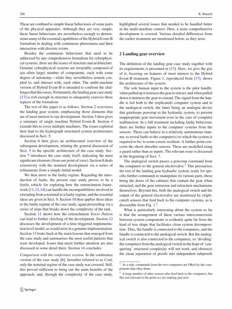
The definition of the landing gear case study together withits requirements is presented in [17]. Here, we give the gistof it, focusing on features of most interest to the HybridEvent-B treatment. Figure 1, reproduced from [17], showsthe architecture of the system.
The sole human input to the system is the pilot handle:when pulled up it instructs the gear to retract, and when pulleddown it instructs the gear to extend. The signal from the han-dle is fed both to the (replicated) computer system and tothe analogical switch, the latter being an analogue devicethat gatekeeps powerup to the hydraulic system, to preventinappropriate gear movement even in the case of computermalfunction. In a full treatment including faulty behaviour,there are further inputs to the computer systems from thesensors. These can behave in a relatively autonomous man-ner, to reveal faults to the computer(s) to which the system isrequired to be, to some extent, resilient. A further point con-cerns the shock absorber sensors. These are modelled usinga guard rather than as inputs. The relevant issue is discussedat the beginning of Sect. 7.
The analogical switch passes a powerup command fromthe computers to the general electrovalve.1 This pressurisesthe rest of the landing gear hydraulic system, ready for spe-cific further commands to manipulate its various parts, thesebeing the doors of the cabinets that contain the gear whenretracted, and the gear extension and retraction mechanismsthemselves. Beyond this, both the analogical switch and theoutput of the general electrovalve are monitored by (tripli-cated) sensors that feed back to the computer systems, as isdiscernible from Fig. 1.2
What is particularly interesting about the system so faris that the arrangement of these various interconnectionsbetween system components is evidently quite far from thekind of tree shape that facilitates clean system decomposi-tion. Thus, the handle is connected to the computers, and thehandle is connected to the analogical switch. But the analog-ical switch is also connected to the computers, so ‘dividing’the computers from the analogical switch in the hope of ‘con-quering’ structural complexity will not work, and obstructsthe clean separation of proofs into independent subproofs
1 As a rule, commands from the two computers are ORed by the com-ponents that obey them.2 A large number of other sensors also feed back to the computers, butthis not relevant to the point we are making just now.
123

The landing gear system in multi-machine Hybrid Event-B 207
Front door cylinder
Right door cylinder
Left door cylinder
Aircraft hydraulic circuit
General electro-valve
Electro-valve (close doors)
Electro-valve (open doors)
Electro-valve (retract gears)
Electro-valve (extend gears)
Front gear cylinder
Right gear cylinder
Left gear cylinder
Ord
ers
to e
lect
ro-v
alve
s
From discrete sensors (gear extended / not extended, gear retracted / not retracted, door closed / not closed, door open / not open, …)
Discrete sensor (pressure OK / not OK)
(retraction circuit)
(retraction circuit)
(extension circuit)
(extension circuit)
Analogical switch
Towards the cockpit
Fig. 1 Architectural overview of the landing gear system, reproduced from [17]
concerning analogical switch and computers separately. Thisposes a significant challenge for our modelling methodology,and gave rise to the need for new interconnection mechanisms(at least it did so in Conf), as discussed in Sects. 4 and 6.
Beneath the level of the general electrovalve, it is a loteasier to see the system as comprised of the computers onthe one hand, and the remaining hydraulic components onthe other, connected together in ways that are rather moretractable by readily understood interconnection mechanisms.
Since there is presently no specific tool support for HybridEvent-B, our case study is primarily an exploration of mod-elling capabilities. As explained below, a major element ofthis is the challenge of modelling physically separate compo-nents in separate machines, and of interconnecting all thesemachines in ways appropriate to the domain, all supportedby relevant invariants. Depending on the complexity of theinterconnection network, this can require novel machineinterconnection mechanisms, introduced for pure Event-Bin [5]. The suitability of proposals for such mechanisms can
only be tested convincingly in the context of independentlyconceived substantial case studies like this one, so it is grati-fying that the mechanisms exercised here fare well in the faceof the complexities of the requirements of the case study.
3 Hybrid Event-B, single machines
In this section we look at Hybrid Event-B for a singlemachine. In Fig. 2, we see a bare bones Hybrid Event-Bmachine, HyEvBMch. It starts with declarations of time andof a clock. In Hybrid Event-B, time is a first class citizen inthat all variables are functions of time, whether explicitly orimplicitly. However, time is special, being read-only. Clocksallow more flexibility, since they are assumed to increaselike time, but may be set during mode events (see below).Variables are of two kinds. There are mode variables (like u)which take their values in discrete sets and change their valuesvia discontinuous assignment in mode events. There are also
123

208 R. Banach
Fig. 2 A schematic Hybrid Event-B machine
pliant variables (such as x,y), declared in the PLIANT clause,which typically take their values in topologically dense sets(normally R) and which are allowed to change continuously,such change being specified via pliant events (see below).
Next are the invariants. These resemble invariants in dis-crete Event-B, in that the types of the variables are assertedto be the sets from which the variables’ values at any givenmoment of time are drawn. More complex invariants are sim-ilarly predicates that are required to hold at all moments oftime during a run.
Then, we have the events. The INITIALISATION has aguard that synchronises time with the start of any run, whileall other variables are assigned their initial values as usual.
Mode events are direct analogues of events in discreteEvent-B. They can assign all machine variables (except timeitself). In the schematic MoEv of Fig. 2, we see three para-meters i?,l,o!, (an input, a local parameter, and an output,respectively), and a guard grd which can depend on all themachine variables. We also see the generic after-value assign-ment specified by the before-after predicate BApred, whichcan specify how the after-values of all variables (except time,inputs and locals) are to be determined.
Pliant events are new. They specify the continuous evo-lution of the pliant variables over an interval of time. Theschematic pliant event PliEv of Fig. 2 shows the structure.There are two guards: there is iv, for specifying enablingconditions on the pliant variables, clocks, and time; andthere is grd, for specifying enabling conditions on the modevariables. The separation between the two is motivatedby considerations connected with refinement. (For a moredetailed discussion of issues such as this, see [9].)
The body of a pliant event contains three parametersi?,l,o!, (again an input, a local parameter, and an output)which are functions of time, defined over the duration of thepliant event. The behaviour of the event is defined by theCOMPLY and SOLVE clauses. The SOLVE clause speci-fies behaviour fairly directly. For example, the behaviour ofpliant variable y and output o! is given by a direct assign-ment to the (time dependent) value of the expression E(…).
Alternatively, the behaviour of pliant variable x is given bythe solution of the first-order ordinary differential equation(ODE) D x = φ(. . .), where D indicates differentiation withrespect to time (In fact, aside from some small technicaldetails, the semantics of the y,o! = E case is given in terms ofthe ODED y,D o! = D E , so that x, y and o! satisfy the sameregularity properties). The COMPLY clause can be used toexpress any additional constraints that are required to holdduring the pliant event via its before-during-and-after predi-cate BDApred. Typically, constraints on the permitted rangeof values for the pliant variables, and similar restrictions, canbe placed here.
The COMPLY clause has another purpose. When spec-ifying at an abstract level, we do not necessarily want tobe concerned with all the details of the dynamics—it isoften sufficient to require some global constraints to holdwhich express the needed safety properties of the system. TheCOMPLY clauses of the machine’s pliant events can housesuch constraints directly, leaving it to lower level refinementsto add the necessary details of the dynamics. (In fact, a majoruse to which we put the COMPLY capability in our case studyis to demand that pliant variables, which would otherwise beunconstrained during a (n essentially default) pliant event,remain constant during it. This is mentioned in Sect. 10.)
Briefly, the semantics of a Hybrid Event-B machine is asfollows. It consists of a set of system traces, each of whichis a collection of functions of time, expressing the value ofeach machine variable over the duration of a system run. (Inthe case of HyEvBMch, in a given system trace, there wouldbe functions for clk,x,y,u, each defined over the duration ofthe run.)
Time is modelled as an interval T of the reals. A runstarts at some initial moment of time, t0 say, and lasts eitherfor a finite time, or indefinitely. The duration of the run T
breaks up into a succession of left-closed right-open subinter-vals: T = [t0 . . . t1), [t1 . . . t2), [t2 . . . t3), . . .. The idea is thatmode events (with their discontinuous updates) take place atthe isolated times corresponding to the common endpoints ofthese subintervals ti , and in between, the mode variables are
123

The landing gear system in multi-machine Hybrid Event-B 209
constant and the pliant events stipulate continuous change inthe pliant variables.
Although pliant variables change continuously (exceptperhaps at the ti ), continuity alone still admits a wide rangeof mathematically pathological behaviours. (For example,speaking measure-theoretically, ‘most’ continuous functionsare non-differentiable almost everywhere.) To eliminate suchpathologies, we insist that on every subinterval [ti . . . ti+1)
the behaviour is governed by a well-posed initial value prob-lem D xs = φ(xs . . .) (where xs is a relevant tuple of pliantvariables and D is the time derivative). ‘Well posed’ meansthat φ(xs . . .) has Lipschitz constants which are uniformlybounded over [ti . . . ti+1) bounding its variation with respectto xs, and that φ(xs . . .) is measurable in t. Moreover, thepermitted discontinuities at the boundary points ti enable aneasy interpretation of mode events that happen at ti .
The differentiability condition guarantees that from a spe-cific starting point, ti say, there is a maximal right-openinterval, specified by tMAX say, such that a solution to theODE system exists in [ti . . . tMAX). Within this interval, weseek the earliest time ti+1 at which a mode event becomesenabled, and this time becomes the preemption point beyondwhich the solution to the ODE system is abandoned, andthe next solution is sought after the completion of the modeevent.
In this manner, assuming that the INITIALISATION eventhas achieved a suitable initial assignment to variables, a sys-tem run is well formed, and thus belongs to the semantics ofthe machine, provided that at runtime:
• Every enabled mode event is feasible, i.e. has anafter-state, and on its completion enables a pliantevent (but does not enable any mode event).3 (1)
• Every enabled pliant event is feasible, i.e. has a time-indexed family of after-states, and EITHER: (2)
(i) During the run of the pliant event, a mode eventbecomes enabled. It preempts the pliant event,defining its end. ORELSE
(ii) During the run of the pliant event, it becomes infea-sible: finite termination. ORELSE
(iii) The pliant event continues indefinitely: nontermi-nation.
Thus, in a well-formed run mode events alternate with pli-ant events. The last event (if there is one) is a pliant event(whose duration may be finite or infinite). In reality, there area number of semantic issues that we have glossed over in theframework just sketched. We refer to [9] for a more detailedpresentation.
3 If a mode event has an input, the semantics assumes that its value onlyarrives at a time strictly later than the previous mode event, ensuringpart of (1) automatically.
We point out that the presented framework is quite close tothe modern formulation of hybrid systems. See, e.g. [27,32]for representative modern formulations, or [19] for a per-spective stretching further back.
4 Top-down modelling of complex systems, andmultiple cooperating Hybrid Event-B machines
The principal objective in modelling complex systems in theB-Method is to start with small simple descriptions and torefine to richer, more detailed ones. This means that, at thehighest levels of abstraction, the modelling must abstractaway from concurrency. By contrast, at lower levels ofabstraction, the events describing detailed individual behav-iours of components become visible. In a purely discreteevent framework, like conventional Event-B, there can besome leeway in deciding whether to hold all these low-levelevents in a single machine or in multiple machines—becauseall events execute instantaneously, isolated from one anotherin time (in the usual interpretation), and in between, nothingchanges.
4.1 Multi-machine systems via INTERFACEs
In Hybrid Event-B, the issue just mentioned is more press-ing. Because of the continuous behaviour that is represented,all components are always executing some event. Thus,an integrated representation risks hitting the combinatorialexplosion of needing to represent each possible combinationof concurrent activities within a separate event, and there is amuch stronger incentive to put each (relatively) independentcomponent into its own machine, synchronised appropri-ately. To put it another way, there is a very strong incentiveto not abstract away from concurrency, an impulse thatmatches with the actual system architecture. In Hybrid Event-B, there is thus an even greater motivation than usual for therefinement methodology to make the step from monolithicabstract and simple descriptions to more detailed and con-crete concurrent descriptions, convincingly.
In our approach, this is accomplished using normal HybridEvent-B refinement up to the point where a machine is largeenough and detailed enough to merit being split up. After that,the key concept in the decomposition strategy is the INTER-FACE construct. This is adapted from the similarly namedidea in [21], to include not only declarations of variables(as in [21]), but of the invariants that involve them, and alsotheir initialisations. (Thus, an interface becomes a kind ofshell of a machine, except one without any specific events tochange the variables’ values, and thus permitting any changeof value imposed by the events of a machine accessing theinterface, provided it preserves the invariants.) A communityof machines may have access to the variables declared in an
123

210 R. Banach
interface provided each such machine CONNECTS to theinterface. All events in such machines must preserve all ofthe invariants in the interface, of course. An important pointis that all invariants involving the interface’s variables mustbe recorded in the interface, which assists a (putative) toolto mechanically monitor whether all the needed proof oblig-ations in the verification of a machine have been adequatelydischarged.
The way that this strategy is defined in [5] and in[10] means that provided the relevant combinatorial rulesare followed regarding what is visible where, the ideasjust described can serve equally well as a discipline forcomposing separate (and in principle, independently con-ceived) components in a component-based system construc-tion discipline. This gives an alternative to the refinementand decomposition-based methodology just discussed. Ofcourse, with suitable attention to the formal details, bothapproaches can coexist. A combination of refinement ideasand composition ideas can be used in the same development,since the addition of new components to a system can beviewed as a refinement of the system at the component level,analogously to the way that addition of new variables andtheir behaviours to an individual component is a refinementof the system at the level of variables. The paper [5] gives abrief description aimed at the (familiar, discrete-only) Event-B context, whereas [10] gives a more detailed discussion,taking all the additional considerations of Hybrid Event-Binto account, and explaining how (de)composition and refine-ment all can be viewed as different sides of the same coin.
4.2 Type II invariants in multi-machine systems
Although we said above that an interface contains all ofthe invariants mentioning any of its variables, in practicethis can be too restrictive. If a system architecture con-tains many components that are tightly coupled in complexways, aggregating all the needed invariants together with thevariables that they mention, when this involves many inter-connected components, may result in a single interface thatis too large and unwieldy for convenient and independentdevelopment. To cater for such an eventuality, the approachdescribed in [5,10] permits also type II invariants (tIIi’s),which are defined to be of the form: U (u) ⇒ V (v), wherevariables u and v belong to different interfaces. This patternfor invariants is sufficient to express many kinds of depen-dency between components, without forcing variables u andv to belong to the same interface, aiding decomposition. Ina tIIi, the u and v variables are called the local and remotevariables, respectively. By convention, a tIIi resides in theinterface containing its local variables, and the remote vari-ables must also reside in an interface. Syntactically, each ofthese interfaces will contain a reference to the other.
By restricting to tIIi’s as the only means of writing invari-ants that cross-cut across two interfaces (and, implicitly,across the machines that access them), we can systematise,and then conveniently mechanise, the verification of suchinvariants. Thus, for a tIIi like U (u) ⇒ V (v), it is suffi-cient for events that update the u variables to preserve ¬U(if it is true in the before-state) and for events that updatethe v variables to preserve V (if it is true in the before-state).These observations are helpful in ‘dividing and conquering’the verification task to promote separate working, while yetbeing sufficient to express a large fraction of the propertiesthat may be required to hold between two different machines.
4.3 Synchronisation in multi-machine systems
As well as sharing variables via interfaces, multi-machineHybrid Event-B systems need a mechanism to achieve syn-chronisation between machines—preferably, a mechanismthat is more convenient than creating such a thing ab initiofrom the raw semantics. For this the shared event paradigm[18,30] turns out to be the most convenient. In this scheme,mode event groups, i.e. specified mode events in two (ormore) machines of the system, are deemed to be requiredto execute simultaneously. In practice, it means that for eachsuch event, its guard has to be re-interpreted as the conjunc-tion of the guards of all the events in the group. The restrictionthat only mode events are eligible for such synchronisationsimplifies the theory of the synchronisaiton mechanism con-siderably. Moreover, it proves to be no real restriction at all.According to the semantics sketched in Sect. 3, to launch thesynchronised execution of a family of pliant events spreadacross several machines, it would be sufficient to arrange (viathe mode event synchronisation mechanism) the synchro-nised execution of a corresponding family of mode eventswhose primary purpose was to enable all the pliant events.But this is easy to program in general.
5 Hypergraph-based system architectures
The sections above described an armoury of techniques thatcan be applied to the problem of system specification anddevelopment. However, by itself, this gives no advice abouthow these techniques ought to be used in any particular case.Here, we give some guidance on that point.
Our principal recommendation is that wherever possible,systems should have a hypergraph architecture. In thelight of the commentary above, this means that there shouldbe a hypergraph in which the machines of the systems consti-tute the nodes, and the interfaces should form the hyperedgesconnecting families of nodes (i.e. machines).4
4 An equivalent way of saying the same thing is the familiar recastingof hypergraphs as bipartite conventional graphs, with machine nodes
123

The landing gear system in multi-machine Hybrid Event-B 211
What this implies is that the variables that a machineneeds to manipulate at various times typically split into anumber of constituencies, each focused on a different con-cern. In turn, each such concern may involve a number ofmachines to achieve its goals. Provided the concerns do notoverlap, the variables for each concern will be distinct fromthe variables for other concerns, and can thus be placed in aninterface focused on that concern, to be manipulated by themachines that are involved with that concern as necessary. Inthis manner, we arrive at the machine = node and interface= hyperedge hypergraph structure.
This system architecture proposal is well validated in thelanding gear case study. In the Conf version, this patternwas not followed (for reasons explained below). Instead,interfaces were associated with machines, each containingthe variables typically written by that machine. Each Confmachine also needed access to interfaces containing thevariables it read but did not update. Although this was areasonable proposal architecturally, expressing dependenciesbetween machines was made more cumbersome. A good dealof use was made of the tIIi mechanism discussed earlierto express needed dependencies, with the attendant cross-referencing between interfaces.
In the present development, a different tack was takenregarding a specific design decision (we give the specificdetails in Sect. 8). This made the hypergraph structure muchmore convenient. As a result of the different structure, alluses of the tIIi mechanism were eliminated in the presentwork. This was a byproduct of the hypergraph architecturethat was quite unexpected (until the detailed work revealedit). This simplification of the architectural challenge via ahypergraph structure leads to our promoting it as a genericgood thing. Of course, the tIIi mechanism remains avail-able for situations in which even the hypergraph architectureimplies a need for sufficiently complex cross-cutting inter-dependencies between machines and interfaces.
Of course, the issues we have discussed above need to bemanaged at the syntactic level. In [10], we describe in detailhow this is done via the PROJECT file. At a given level of adevelopment, the project file takes care of four issues. First, itlists the components (interfaces and machines) that constitutethe system at that level. Second, it defines the synchronisa-tions that need to hold between individual machine events.Third (though not relevant for the present development), itis the place where instantiation issues can be dealt with (ina component-based methodology using a component repos-itory, or similar). Fourth, it can contain a reference to a fileof global invariants; these would be overreaching invariants,
Footnote 4 continuedand interface nodes, and edges that connect a single machine to a sin-gle interface (Then, each interface node, with all its incident edges,constitutes a hyperedge of the previous description).
derivable from the contents of all the interfaces of the project,to be used as required in the development process.
6 Case study architectural overview
In this section, we describe how the preceding ideas play outin the landing gear case study. Figure 3 shows the systemarchitecture. Rectangles represent components of the sys-tem; rounded corners for machines and unrounded cornersfor interfaces. Figure 3 splits into three phases. The first, atthe top, shows the very first model: Level_00_PilotAndLightsNominal. This is then refined and decomposed at level 01 intothree machines: Level_01_PilotNominal, Level_01_Comp1Nominal, Level_01_Comp2Nominal. The decomposition isrepresented by the diagonal dashed lines in the figure.
Below the higher horizontal dashed line is the remainderof the nominal development. Machine suffixes are ‘Nominal’,interface suffixes are ‘_IF’. The nominal development itselfconsists of levels 00, 01, 02, 03, 04, 05, 06, 07. The series ofnumbers in each rectangle indicate the development levels atwhich components are introduced or changed. Thus, at level04, the development consists of Pilot, Central_IF, Comp1,
Comp2, AnalogicalSwitch, General_EV .The solid lines represent the CONNECTS relationships
between machines and interfaces. Since each such line indeedjoins a machine to an interface, the bipartite graph represen-tation of the hypergraph structure is clear from the structureof the middle layer of Fig. 3, so that all levels of the nominaldevelopment fit it. Thus, Central_IF contains the variablesthat embody the interaction between the computers, and theanalogical switch and general electrovalve, while Hydraulic-Cylinders_EV_IF contains the variables that embody theinteraction between the computers and the hydraulic cylin-ders. The important point is that these sets of variables aredisjoint, leading to a clean structure.
Below the second dashed line is the faulty develop-ment. Whereas the nominal development is accomplishedentirely using refinement and refinement-compatible tech-niques, the faulty development entails departures from pre-viously established behaviours. We deal with this usingretrenchment, in two development levels: 10 and 11. Thefaulty level identifiers are separated from the nominalones by writing two slashes in the level number series ofeach component. The shadows behind the interface compo-nents Central_IF_Faulty and HydraulicCylinders_EV_IF_Faulty denote the Nominal versions that the faulty versionshave been retrenched from, and which still play a role behindthe scenes in the faulty development. All this is explainedbelow. Clearly, the earlier hypergraph structure persists.
Regarding the nature of the refinements used in this casestudy, it is worthwhile pointing out that, overwhelmingly, thesuccessive levels of the modelling refine their predecessor
123

212 R. Banach
PilotAndLightsNominal00
PilotNominal01 Central_IF
03/04/05
Comp1Nominal01/03/04/05/06/07
Comp2Nominal01/03/04/05/06/07
HydraulicCylinders_EV_IF06
DoorsOpen_EV_Nominal06
DoorsClose_EV_Nominal06
GearExtend_EV_Nominal06
GearRetract_EV_Nominal06
PilotFaulty01//11
Comp1Faulty01/03/04/05/06/07//11
Comp2Faulty01/03/04/05/06/07//11
HydraulicCylinders_EV_IF_Faulty06//10
DoorsOpen_EV_Faulty06//10
DoorsClose_EV_Faulty06//10
GearExtend_EV_Faulty06//10
GearRetract_EV_Faulty06//10
AnalogicalSwitchNominal02/03/04 General_EV_Nominal
04/05
AnalogicalSwitchFaulty02/03/04//10 General_EV_Faulty
04/05//10
Cockpit_IF_Faulty11
Central_IF_Faulty03/04/05//11
Fig. 3 Overview of the multi-machine Hybrid Event-B landing gearsystem development architecture. Rectangles depict interfaces (suffix‘_IF’ for nominal regime interfaces, ‘_IF_Faulty’ for faulty regimeinterfaces). Rounded rectangles depict machines (suffix ‘Nominal’ for
nominal regime machines and ‘Faulty’ for faulty regime machines).Numbers associated with components indicate the development levels(from 00,01,02,03,04,05,06,07 nominal, 10,11 faulty) at which compo-nents are introduced or undergo change
levels by the aggregation of fresh design detail. This makesthe details of the refinement (and in particular the details ofthe verification of the refinement via the requisite proof oblig-ations) relatively trivial. The refinement relation betweentwo successive levels is just a projection from the concretelevel to the abstract level that forgets the newly introduceddetail. Although on the face of it this fails to exercise the datarefinement capabilities of Hybrid Event-B to any significantdegree, by contrast, the fact that real time is treated a just aparameter in Hybrid Event-B implies that any nontrivial datarefinement will work by simply applying a discrete eventstyle data refinement to the abstract and concrete variablesin a parameterised way.
The exception to these remarks for this case study arises inthe use of retrenchment, in which greater variance betweenabstract variables and their concrete counterparts is requiredthan can be accommodated via refinement. However, it turnsout that capturing these relationships between abstract andconcrete can only be done using the additional machinery
found in retrenchment, whereas the refining parts of the rela-tionships remain as simple as before. This rather reinforcesthe preceding point.
7 Model development preliminaries
Having covered the architectural issues, we now look at thedevelopment in more detail. We start by clarifying our inter-pretation of some minor inconsistencies in the spec [17].First, we assume that the pilot controls the gear via a han-dle for which handle UP means gear up, and handle DOWNmeans gear down. We also assume that in the initial statethe gear is down and locked, since the aircraft does not levi-tate when stationary on the ground, presumably. Connectedwith this requirements aspect is the absence of provision in[17] of what is to happen if the pilot tries to pull the handleup when the aircraft is not in flight. Presumably the aircraftshould not belly-flop to the ground, so we just incorporatea suitable guard on the handle movement events, based on
123

The landing gear system in multi-machine Hybrid Event-B 213
the value of the shock absorber sensors. This leaves open thequestion of what would actually happen if the pilot pulled thehandle up when the plane is on the ground. Does the handleresist the movement, or does gear movement remain pend-ing until released by the state of the shock absorber sensors,or . . .?
This issue, in turn, raises a further interesting question.Although the fact just pointed out causes no special problemfor an event-by-event verification strategy like the B-Method,the absence of any explicit requirement that allows the shockabsorber to change value would be equivalent to the aircraftnever leaving the ground, leading to the absence of any non-trivial gear manipulation traces for a trace-based verificationstrategy to work on. Thus, for a model checking approach ofany kind to work, suitable additional events would have to beintroduced into the model, for just the purpose of allowingthe aircraft to leave the ground.
Pursuing the technical strategy advocated earlier, amongother things implies that in the final development, each com-ponent that is identifiable as a separate component in thearchitectural model should correspond to a machine in itsown right. Thus, at least, we should have separate machinesfor: the pilot subsystem (handle and lights), the two com-puters, the analogical switch, the general electrovalve, andthe individual movement electrovalves (and their associatedhydraulic cylinders). In concert with this was the desire touse variables that correspond directly to quantities discussedin the requirements document. The aim was to strive for theclosest possible correspondence between requirements andformal model, in the belief that this improves the engineeringprocess. It is possible that this perspective led to a granularityin the modelling which was not optimally efficient. However,the main priority in this study was to challenge the expres-sivity of the framework, rather than to test the efficiency ofany putative tool implementation.
In addition to the above, the requirements concerned withthe faulty regime in [17] mention the variables normal_modeand anomalyk , without going into any explanation abouttheir further purpose. This made it less clear how best tomodel these requirements. In the end, it was decided tocreate a fresh interface Level_11_Cockpit_IF_Faulty to con-tain those variables (and other quantities were convenientlyincluded there too). This would in fact be needed if those vari-ables were to be used by machines that modelled a cockpitdisplay, for example (in contrast to the pilot’s lights, whichfall within the scope of the given requirements).
As mentioned earlier, both the Conf development and thepresent one above all constituted modelling challenges forthe Hybrid Event-B formalism. The lessons that had alreadybeen learned from Conf were applied in the present develop-ment (see Sect. 8), which in turn generated further questionsto be considered in future (see Sect. 13 for those). One notableelement of this process was the change to the hypergraph
architecture, which so dramatically eliminated the need forany type II invariants between interfaces.
8 The nominal regime
We now comment on the various levels of the nominal devel-opment, level by level. Along the way, we describe furthernotational conventions used in the development, as we didfor the architectural overview already given. Adhering tothe vision of the B-Method, the development starts verysimply, and proceeds to add detail via layers of refinementand composition, with most of the steps of the developmentbeing quite small. Table 1 summarises the nominal devel-opment levels. The full details of the models in each levelcan be found at [3], with each level defined via the rele-vant PROJECT construct. The site [3] contains not only thepresent development (with all the levels aggregated into asingle file) but also the previous Conf development.
Level 00. Level 00 starts the development. Because it is sosmall, we can quote a lot of the details, which will be helpfulfor other descriptions below. The PROJECT file for level 00needs only to indicate the PilotAndLightsNominal machine,the sole construct at this level.
The PilotAndLightsNominal machine starts with its name,and the variables introduced for the handle and the green andorange lights. The invariants just state the values these aredrawn from (i.e. their types). The initialisation is obvious
123

214 R. Banach
Table 1 Summary of the levels of the nominal development
Level Feature
00 Pilot’s view
01 Adds two computer machines and decomposes
02 Adds the analogical switch machine
03 Adds the triplicated analogical switch sensors
04 Adds the general electrovalve machine
05 Adds the triplicated general electrovalve sensors
06 Adds the movement electrovalves and hydraulic cylinders
07 Adds the timing automaton
(green is ON initially to indicate that the gear is down whenthe aircraft is in its initial state on the ground), after whichthere are the less trivial events.
PliTrue is the default pliant event—every Hybrid Event-Bmachine needs at least one pliant event because the machinemust describe what is happening at all times, which can-not be done via mode events alone. Pliant event PliTruejust demands that the invariants are maintained, since theprincipal concern of the PilotAndLightsNominal machine iswith the nontrivial mode events. These are PilotGearUP (andthe analogous PilotGearDOWN) and GearStartMoving (andother mode events to switch the orange and green lights onand off).
PilotGearUP has a WHERE guard: handle = DOWN ,which says the handle can only be pulled up if it is down tostart with. The other part of the guard, in? = pilotGearUP_X ,is the Hybrid Event-B metaphor for indicating that the eventis stimulated from the environment and not from some otherpart of the system model. Thus in? denotes an input variable,and pilotGearUP_X is its required value when the input issupplied.5 The body of the event, handle := UP, does notuse the input, so the only role the input plays is to indicate
5 In discrete Event-B, events are assumed to execute lazily, i.e. not atthe very instant they become enabled (according to the normal interpre-tation of how event occurrences map to real time). In Hybrid Event-B,mode events must execute eagerly, i.e. as soon as they are enabled (inreal time), to model physical phenomena.This is because physical law is similarly eager: if a classical physi-cal system reaches a state in which some transition is enabled, it isoverwhelmingly the case that energetics and thermodynamics force thetransition to take place straight away. Hybrid Event-B, in being designedto model physical systems, must therefore conform to this. As a conse-quence, typical Event-B models, in which a new after-state immediatelyenables the next transition, would cause an avalanche of mode eventoccurrences if interpreted according to Hybrid Event-B semantics.To avoid this, and yet to allow the modelling convenience of permittinglazily executed mode events in Hybrid Event-B, the convention is thatif a mode event has an input, at runtime the input value arrives at sometime strictly later than the time of execution of the previous mode event,thus introducing a delay—if there is no input, execution is eager. Thedelay is nonzero, but undetermined unless more precisely constrainedby restrictions in the event’s guard. So having an input is the HybridEvent-B metaphor for ensuring lazy execution, even if the input valueis not used.
the asynchronous timing of the event. The suffix ‘_X’ on theinput value is a naming convention used in this developmentto indicate the use of this metaphor.
The GearStartMoving event is very similar to the eventPilotGearUP we just discussed, except that there is no termorange = OFF in the guard; we explain this shortly. Thiscompletes level 00.
Level 01. Level 01 REFINESandDECOMPOSES the level00 machine PilotAndLightsNominal. In detail, it first intro-duces the first collection of variables needed for the twocomputing machines, Comp1 and Comp2, and then sec-ond, decomposes the result into the three separate level 01machines: PilotNominal, Comp1Nominal, Comp2Nominal,furthermore doing all this in one step to save verbosity.
The relationship between these machines deserves com-ment. Each of the level 00 mode events has become, at level01, an event that is synchronised between an event in Pilotand another in Comp1 or Comp2. As another notational con-vention, events which are synchronised are named with a_S suffix for visibility, although the actual definitions of thesynchronisations are in the level 01 project file. The handlemovement events are initiated by the pilot, so are modelledas previously, with, e.g. an in? = pilotGearUP_X guard toindicate the source of the external initiative for the event. Thecorresponding Comp1 or Comp2 events merely synchronisepassively and update a corresponding variable. On the otherhand, the lights switching on and off events are initiated bythe computers, in response to (as yet undefined) behaviour inthe rest of the system, so the in? = gearStartMoving_X guardmoves from the pilot machine to the computer machines forthese events, and this time, it is the pilot machine that syn-chronises passively.6
At this point, we hit the most significant differencebetween the Conf development and this one. Although it isnot visible in Fig. 1, the communication from pilot to com-puters is a wired AND, and from computers to pilot is a wiredOR. In Conf, some effort was made to model this faithfully,creating a machine to serve as the fictional single comput-ing system presented to the pilot, interacting with the tworeal computers. This modelling style entailed the fictionalcomputer synchronising with each of the two real comput-ers, and proved to be extremely verbose—the authenticitywas far outweighed by the obfuscating verbosity. Suffice itto say that the corresponding part of the present developmentoccupies about a third of the text of the Conf development. Itwas this aspect, mainly, that made a hypergraph architectureexcessively cumbersome in Conf, without the realisation (atthe time), of how much modelling convenience was beinggiven up by doing so.
6 Ultimately, the spontaneous occurrences of the GearStartMoving (andsimilar) events in the Comp machines will be refined to the more deter-ministic behaviour of more complete computing machines.
123

The landing gear system in multi-machine Hybrid Event-B 215
CLOSED_INIT CLOSED_FIN OPEN0
•••• •
clk_AnSw
Fig. 4 The analogical switch machine’s transitions when interruptedby a fresh handle event
In the present development, there is no fictional com-puter, and the OR is done in the pilot machine rather thanoutside—so the modelling is slightly less authentic. It turnsout that this has consequences. If a single pilot event (suchas the pilot’s GearStartMoving_S) has to synchronise witheach of the two computers’ corresponding events (called alsoGearStartMoving_S in Comp1 and Comp2) then, assumingsome asynchrony between Comp1 and Comp2, the pilot’sGearStartMoving_S would be executed twice. This meansthat the pilot’s event must be idempotent—executing it a sec-ond time needs to have no effect.7
Now, we see why there was no orange = OFF guard inGearStartMoving_S earlier. If there had been, the secondoccurrence of GearStartMoving_S would have been disabledin the pilot machine, causing problems.8
We have discussed this point with some care because thesame issue arises every time the computers issue commandsto any of the remaining equipment, e.g. to the analogicalswitch, or to the hydraulic apparatus. In all such cases, thesynchronised event in the receiving machine must be idem-potent.
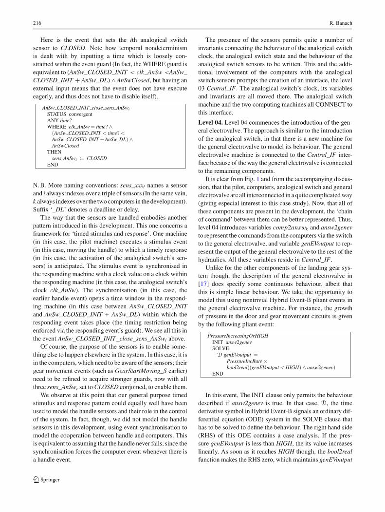
Level 02. Level 02 introduces the analogical switch. Theanalogical switch is open by default. When a handle eventoccurs, the switch slowly closes (which takes from time 0till time CLOSED_INIT ), remains closed for a period (fromtime CLOSED_INIT till time CLOSED_FIN , allowing theonward transmission of commands from the computers tothe general electrovalve), and then slowly opens again (fromtime CLOSED_FIN till time OPEN). If a handle event occurspart way through this process, Fig. 4 shows how the behaviouris affected: during closing, no effect; while closed, the closedperiod is restarted; during reopening, closing is restarted froma point proportional to the remainder of the reopening period.
A clock, clk_AnSw (clk_xxx being another naming con-vention, used for clocks), controls this activity. For this towork, the pilot’s handle events are further synchronised withanalogical switch events that reset clk_AnSw to the appro-
7 Dealing with this properly in the Conf development caused the major-ity of the excessive verbosity.8 It may be argued that the phenomenon being discussed is absent atlevel 00, so the guard could have been included there, and removed atlevel 01, but in Event-B refinement, guards are strengthened, so thiswould have prevented the 00 to 01 development step from being anEvent-B refinement.
priate value, depending on its value at the occurrence of thehandle event (N. B. The pilot’s handle events reach the ana-logical switch directly, and not via the computing modules,this being part of the complex interaction between pilot, ana-logical switch, and general electrovalve).
Two further events (AnSw_CLOSED_INIT_reached andAnSw_CLOSED_FIN_reached) mark the transitionsbetween episodes: from closing to closed, and from closedto reopening. Since these are ‘new’ events in an Event-Brefinement, their STATUS is convergent, and a (N-valued)VARIANT is included in the analogical switch machine, thatis decreased on each occurrence of either of them. As usual,since N is well founded, the decrease of the variant impliesthat the new events cannot continue to occur indefinitelywithout the occurrence of ‘old’ events.
We dwelt on this last point a little since it introduces auseful pattern in the development that is reused a number oftimes below. Suppose an activity, engaged in by a number ofactors, needs to progress through a series of tasks t1,t2,t3, cir-cumscribed by a series of deadlines: DL1 < DL2 < DL3,
all the deadlines being measured from a common startingpoint. Then, a useful variant that is decreased by events thatmark the completion of the stages within the deadlines is:
No. of actors yet to complete t1 within DL1 +No. of actors yet to complete t2 within DL2 +No. of actors yet to complete t3 within DL3 +0 × No. of actors past DL3
If the actors need to be in a specific state at each stage, etc. thiscan be built into the expressions occurring above. The ideais that as each actor completes the tasks and the deadlinesexpire in turn, the expressions above stop contributing to thevariant, ensuring its decrease.
Level 03. Level 03 introduces the (triplicated) analogicalswitch sensors. The main reason for not doing this in the pre-vious level is to exercise the composition and architecturalfeatures of the multi-machine formalism, to confirm that itis flexible enough to cope with this kind of gradual elabo-ration of components that are already present. In contrast tothe Conf development, in this development, sensors respondasynchronously: each sensor is permitted to respond in itsown right within a small time window following the closureor opening of the switch. This requires more ‘new’ events,and the variant that ensures their convergence is based oncemore on the pattern just described.9
9 In fact, the most compact way of writing the variant requires count-ing the identities of sensors satisfying the requisite properties. Strictlyspeaking this is outside the usual kind of B-Method type system, butit could be simulated by some more cumbersome programming. In ourpaper exercise, we sidestep this problem for the sake of clarity.
123
216 R. Banach
Here is the event that sets the ith analogical switchsensor to CLOSED. Note how temporal nondeterminismis dealt with by inputting a time which is loosely con-strained within the event guard (In fact, the WHERE guard isequivalent to (AnSw_CLOSED_INIT < clk_AnSw <AnSw_CLOSED_INIT + AnSw_DL)∧ AnSwClosed, but having anexternal input means that the event does not have executeeagerly, and thus does not have to disable itself).
N. B. More naming conventions: sens_xxxi names a sensorand i always indexes over a triple of sensors (In the same vein,k always indexes over the two computers in the development).Suffix ‘_DL’ denotes a deadline or delay.
The way that the sensors are handled embodies anotherpattern introduced in this development. This one concerns aframework for ‘timed stimulus and response’. One machine(in this case, the pilot machine) executes a stimulus event(in this case, moving the handle) to which a timely response(in this case, the activation of the analogical switch’s sen-sors) is anticipated. The stimulus event is synchronised inthe responding machine with a clock value on a clock withinthe responding machine (in this case, the analogical switch’sclock clk_AnSw). The synchronisation (in this case, theearlier handle event) opens a time window in the respond-ing machine (in this case between AnSw_CLOSED_INITand AnSw_CLOSED_INIT + AnSw_DL) within which theresponding event takes place (the timing restriction beingenforced via the responding event’s guard). We see all this inthe event AnSw_CLOSED_INIT_close_sens_AnSwi above.
Of course, the purpose of the sensors is to enable some-thing else to happen elsewhere in the system. In this case, it isin the computers, which need to be aware of the sensors; theirgear movement events (such as GearStartMoving_S earlier)need to be refined to acquire stronger guards, now with allthree sens_AnSwi set to CLOSED conjoined, to enable them.
We observe at this point that our general purpose timedstimulus and response pattern could equally well have beenused to model the handle sensors and their role in the controlof the system. In fact, though, we did not model the handlesensors in this development, using event synchronisation tomodel the cooperation between handle and computers. Thisis equivalent to assuming that the handle never fails, since thesynchronisation forces the computer event whenever there isa handle event.
The presence of the sensors permits quite a number ofinvariants connecting the behaviour of the analogical switchclock, the analogical switch state and the behaviour of theanalogical switch sensors to be written. This and the addi-tional involvement of the computers with the analogicalswitch sensors prompts the creation of an interface, the level03 Central_IF. The analogical switch’s clock, its variablesand invariants are all moved there. The analogical switchmachine and the two computing machines all CONNECT tothis interface.
Level 04. Level 04 commences the introduction of the gen-eral electrovalve. The approach is similar to the introductionof the analogical switch, in that there is a new machine forthe general electrovalve to model its behaviour. The generalelectrovalve machine is connected to the Central_IF inter-face because of the way the general electrovalve is connectedto the remaining components.
It is clear from Fig. 1 and from the accompanying discus-sion, that the pilot, computers, analogical switch and generalelectrovalve are all interconnected in a quite complicated way(giving especial interest to this case study). Now, that all ofthese components are present in the development, the ‘chainof command’ between them can be better represented. Thus,level 04 introduces variables comp2answk and answ2genevto represent the commands from the computers via the switchto the general electrovalve, and variable genEVoutput to rep-resent the output of the general electrovalve to the rest of thehydraulics. All these variables reside in Central_IF.
Unlike for the other components of the landing gear sys-tem though, the description of the general electrovalve in[17] does specify some continuous behaviour, albeit thatthis is simple linear behaviour. We take the opportunity tomodel this using nontrivial Hybrid Event-B pliant events inthe general electrovalve machine. For instance, the growthof pressure in the door and gear movement circuits is givenby the following pliant event:
In this event, The INIT clause only permits the behaviourdescribed if answ2genev is true. In that case, D, the timederivative symbol in Hybrid Event-B signals an ordinary dif-ferential equation (ODE) system in the SOLVE clause thathas to be solved to define the behaviour. The right hand side(RHS) of this ODE contains a case analysis. If the pres-sure genEVoutput is less than HIGH, the its value increaseslinearly. As soon as it reaches HIGH though, the bool2realfunction makes the RHS zero, which maintains genEVoutput
123

The landing gear system in multi-machine Hybrid Event-B 217
at the high level. In the Conf development, a mode eventseparated these two phases because of the different synchro-nisation of sensors there. In this development, there is nointervening mode event, and the RHS represents a genuinecase analysis.
There is a corresponding pliant event that governs thedecrease of genEVoutput when answ2genev is false. It con-tains a similar case analysis that stops the linear decreaseonce the level drops to LOW. The increasing and decreasingepisodes are separated by mode events that are synchro-nised with the analogical switch’s mode events that moveansw2genev between true and false. This is as required by(1) and (2) above.
We can take this argument further. In reality, a pieceof equipment like the general electrovalve obeys a singlephysical law which would state that the rate of change ofgenEVoutput was governed by a particular physical property(most probably depending on the properties of a hydraulicaccumulator elsewhere in the hydraulic circuit). As such, itwould be fair to define it in Hybrid Event-B using a singleODE such as D genEVoutput = some_expression, leading toa machine with a single plaint event and nothing else. Takingour linear modelling seriously, an explicit such event wouldresemble:
In PressureLaw, the value of answ2genev in the RHSswitches between increasing and decreasing episodes, so theRHS of the ODE now contains a four-way case analysis.In terms of modelling, it does not change much aside fromthe elimination of mode events. In terms of automated ver-ification though, it increases the burden on any automatedanalysis system, since such a system would have to discoverthe four-way case analysis automatically. The range of pos-sibilities considered, from the four pliant events of the Confdevelopment, through the two pliant events of the presentdevelopment, to the single pliant event PressureLaw above,are all connected to the issue of instantiation of a standardcomponent into a specific development. The description in[10] gives a simple proposal, based on simple renaming ofthe elements of a standard component, but there is clearlyscope for more elaborate schemes.
Level 05. Level 05 completes the development of the generalelectrovalve by incorporating its sensors. This is done in thesame way that it was done for the analogical switch. Newevents are introduced in the general electrovalve machine
to assign the sensors, governed by the same asynchronoussetting pattern. Their convergence is confirmed by a variantbuilt according to the same variant pattern we discussed ear-lier. Other events, primarily in the computer machines, arerefined to take note of the sensors.
Of course, most of the preceding could have been accom-plished in many fewer development steps than we expended.The main purpose in the more numerous small steps we tookwas to confirm that such increments of functionality could behandled by the multi-machine formalism without problems.Furthermore, small steps are much easier to handle for auto-mated verification (looking forward to mechanical supportfor Hybrid Event-B).
Level 06. We proceed to level 06. Now, that the generalelectrovalve can be powered up and down, this level intro-duces the individual movement electrovalves, and implicitly,the hydraulic cylinders that they manipulate. Little furtherpurpose is served by slicing the development into smallincrements, given that the patterns for doing this are wellestablished by now, so we introduced all in one step, the fourmovement electrovalves, their sensors, and a new interfaceHydraulicCylinders_EV_IF.
Each of the four movement electrovalves and cylin-ders gives rise to a new machine: DoorsOpen_EV , DoorsClose_EV , GearExtend_EV , GearRetract_EV . These fourmachines are identical in structure, so only DoorsOpen_EV is written out in full. The HydraulicCylinders_EV_IF contains all the variables needed for this step, andthey are coordinated using the same collection of by nowfamiliar patterns.
The Compk machines grow steadily larger due to theaccumulating set of variables that they have to be sensitiveto. They also display an interesting phenomenon. There are‘new’ events to initiate the manipulation of the movementhydraulic cylinders, and to detect the completion of theirmovement tasks. Normally, new events need to decrease avariant. However, during the movement tasks, the handle maybe manipulated an arbitrary number of times, which can evenprolong the task indefinitely if it is a gear movement task. It istrue that ‘old’ events (the handle manipulation events) inter-leave the new event occurrences, and thus it would be possibleto invent state variables that could be used to create a suitablevariant. But such variables would not address any systemrequirements, so they were not introduced. Consequently,the new events were defined with STATUS ‘ordinary’, not‘convergent’. This absolves them from the obligation ofdecreasing any variant (In a more realistic development, suchvariables would typically prove more useful in the faultyregime, but we did not introduce them here; further relatedcomments appear below).
The situation just discussed illustrates a general point.The more an event relies on input or stimulus from the
123

218 R. Banach
Fig. 5 The approximate timingdiagram for the level 07computing machine
0
•• •
•
•
clk_Handle
Gear Extend
Gear Retract
Door CloseDoor Open
• •
gnivoMpotSraeGgnivoMtratSraeG
environment, the weaker are the properties that we canexpect to be able to prove regarding aspects that dependon this external influence—the potentially arbitrary inter-vention of handle movement events during landing gearoperation being a case in point. Only when events dependon variables or stimuli that are fully internalised in themodel, can we expect to prove relatively strong prop-erties regarding them, since we can then identify andthence quantify all the influences that they might dependon.
This portion of the development also shows eloquentlythe benefits of the hypergraph system architecture. Althoughthe computers have to converse with the handle, the analogi-cal switch and the general electrovalve on the one hand, andwith the movement cylinders on the other hand, these con-versations involve separate sets of variables, so the variablescan be conveniently partitioned into the Central_IF and theHydraulicCylinders_EV_IF interfaces, respectively, the sep-aration benefiting separate development.
Level 07. We proceed to level 07. Up to now, the impetus forexecuting any particular event that is potentially available ina machine has come from the environment, via the techniqueof using an external input that is created for that sole purpose.Where there are synchronised families of events, one of themis allocated the external input and the rest are synchronisedwith it. Having reached a fairly complete level of detail inthe nominal regime, the final step in modelling is to removethis artifice, and replace it with explicit timing constraints.This is the job of level 07. We observe that explicit tim-ing information is already included in subsystems for whichthe description is relatively complete, such as the analogi-cal switch, and the general and movement electrovalves, sothe level 07 development step only concerns the computingmodules.
In attempting to incorporate the timing information intothe computing modules, it was tempting to try to intro-duce the timing constraints in a step-by-step fashion. Forexample, one could imagine having only non-overlappingraising and lowering episodes first, and then adding the extracomplexities brought about by allowing raising and lower-ing episodes to overlap. However, it was soon realised thatthe complexity and interconnectedness of the timing con-
straints was such that a stepwise approach would need toallow guard weakening as well as guard strengthening invarious events.10 Since the Event-B notion of refinement isnot designed for guard weakening (the goal of guard weak-ening being delegated to relative deadlock freedom POs), theidea was abandoned in favour of a monolithic approach thatintroduced all of the computing modules’ timing machineryin one go.
Figure 5 outlines the behaviour of the computing mod-ules’ clock clk_Handlek , when the handle is manipulatedduring the course of gear extending or retracting. UnlikeFig. 4 though, where the behaviour illustrated is close towhat the model describes (since the analogical switch justresponds to handle events in a self-contained way), Fig. 5neglects important detail. For example, consider a Pilot-GearUP_S event while the gear is extending. Then, theretracting sequence has to be executed, but only from theposition that the extending sequence has reached. So first,clk_Handlek is changed to stop the gear extending command.Then, the clk_Handlek clock is changed to a time sufficientlybefore the gear retracting command time, that there is cer-tainty that hydraulic hammer11 has subsided. Once it is safeto activate the gear retracting command, the gear retract-ing command is activated, and then clk_Handlek is changedagain to advance the clock in proportion to the undone partof the gear extending activity. In effect, we use clk_Handlek
intervals as part of the state machine controlling the behav-iour of the computing modules (along with some additionalinternal variables). This proves especially convenient whenthe state transitions involved concern delays between com-mands that need to be enforced to assure mechanical safety(e.g. as in the hydraulic hammer case, just discussed). Such
10 For example, introducing conflicting handle events gives rise to theneed to extend the time interval within which certain other events arerequired to occur, thus weakening the event guards that express suchtemporal constraints.11 Hydraulic hammer is the term for the collection of transient shockwaves that propagate round the hydraulic system when relatively abruptchanges are inflicted on its control surfaces (i.e. the pistons in the vari-ous cylinders), and which are typically damped using a relatively elastichydraulic accumulator somewhere in the hydraulic circuit to avoid dam-age to the hydraulic circuit components.
123
The landing gear system in multi-machine Hybrid Event-B 219
fine detail is not visible in Fig. 5, but it makes the designof the level 07 events quite complicated. As a result, thesize of the Compk machines grows considerably at level07; the movement events grow because of the extra detail,but, most particularly, the original handle events are refinedinto a large number of subevents, to cater for all the differ-ent things that need to happen depending on where in thesequence of activities an interruption by a fresh handle eventoccurs.
We can give an example of the preceding in the event Pilot-GearDOWN_DoorsClose_Start_DoorsClose_End_S. It def-ines what happens when the pilot pulls the handle downwhile the doors are closing at the end of a previous manoeu-vre (which must have been a gear retraction manoeuvre, sothat clk_Handlek is between DoorsClose_Start_TIME andDoorsClose_End_TIME). Then, Compk’s clock is movedto just before DoorsClose_End_TIME so that door closurecontrol can be tidied up, doors_open_progress_timek is setto the appropriate portion of the door opening period, andthe doors_open_modek variable is set to INTERRUPTED,so that when reopening is started, the opening event canreact to doors_open_progress_timek instead of opening thedoors from the beginning. By manipulating the clock value,it is easy to allow for the subsidence of hydraulic hammerbefore switching between extension and retraction of thegear.
9 Retrenchment and the introduction of faults
Our technique for incorporating faults into the developmentis based on retrenchment. This is an approach that dates backto [13], especially in the context of the B-Method. More
up to date treatments include [11,12,14,29]. Applicationsto mechanised fault tree construction include [7,8].
Retrenchment is a technique that allows an event to bemodified during a development step more drastically thanpermitted by refinement. This implies that the kinds of guar-antee that refinement can typically offer are missing fromdevelopment steps that are described via retrenchment. In thatsense, retrenchment can be seen as a formally documentedrequirements engineering and requirements modificationframework. Of course, the modification of a nominal modelto incorporate and tolerate faults falls neatly within thisremit.
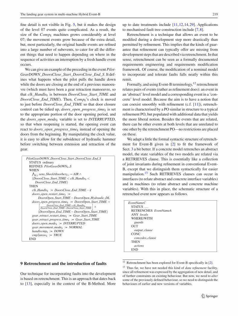
Formally, and using Event-B terminology,12 retrenchmentrelates pairs of events (rather as refinement does): an event inan ‘abstract’ level model and a corresponding event in a ‘con-crete’ level model. Because the aim is to have a notion thatcan coexist smoothly with refinement (c.f. [11]), retrench-ment is characterised by a PO similar in structure to a typicalrefinement PO, but populated with additional data that yieldsthe more liberal notion. Besides the events that are related,there can be other events at both levels that are unrelated toone other by the retrenchment PO—no restrictions are placedon these.
We adapt a little the formal syntactic structure of retrench-ment for Event-B given in [2] to fit the framework ofSect. 3 a bit better. If a concrete model retrenches an abstractmodel, the state variables of the two models are related viaa RETRIEVES clause. This is essentially like a collectionof joint invariants during refinement in conventional Event-B, except that we distinguish them syntactically for easiermanipulation.13 Such RETRIEVES clauses can occur ininterfaces (to relate abstract and concrete interface variables)and in machines (to relate abstract and concrete machinevariables). With this in place, the schematic structure of aretrenched event now appears as follows.
12 Retrenchment has been explored for Event-B specifically in [2].13 Thus far, we have not needed this kind of data refinement facility,since all refinement was expressed by the aggregation of new detail, andof further constraints on existing behaviour. But now, we need to altersome of the previously defined behaviour, so we need to distinguish thebehaviours of earlier and new versions of variables.
123

220 R. Banach
The above shows the details for a mode event; for pli-ant events, the idea is essentially the same, as we describe.After the event name and status, the abstract event that isbeing retrenched is identified. Then, come the guards, whichhave just the same structure as for conventional mode or pli-ant events, as applicable. The WITH alternative is to expressnontrivial relationships between abstract and concrete locals,when needed—this works just as for refinement in conven-tional Event-B. After that come the only visible differencesfrom conventional events, the OUT and CONC clauses. Theidea is that if the simulation of the concrete by the abstractevent is able to reestablish the RETRIEVES relation and allthe invariants, then any additional facts for that case can beaccommodated in the OUT(put) clause. Alternatively, if thesimulation of the concrete by the abstract event is not able toreestablish the RETRIEVES relation and the invariants, thenany relevant facts for that case can be accommodated in theCONC(edes) clause. Both clauses offer maximum expres-sivity, in that abstract and concrete before- and after-valuescan be mentioned in them for mode events. For pliant events,the whole of these variables’ behaviours during the pliantevent are available—thus, they both act as (and thereforereplace) the COMPLY clause, one for the retrieving caseand the other for the conceding case. Given how expres-sive the OUT and CONC clauses are, it is often useful tohave a trivial RETRIEVES relation, delegating all aspects ofthe relationship between abstract and concrete variables tothe WHEN/WITH and OUT and CONC clauses. Below wedescribe how these facilities are used in building the faultyregime of the landing gear case study.
In the literature, various notions that do not conform torefinement have been proposed for incorporating faults intoformal models. These permit the concrete model to departfrom the abstract model in specific ways. In many cases,these ways are, in fact, very similar to what the retrench-ment PO permits. In the cases of interest to us, once faultshave occurred error recovery is modelled, and after it hascompleted, system behaviour is allowed to rejoin refiningbehaviour. In this category, we can cite, e.g. [23] and [24].Their authors typically call their notions by names that are‘flavours of refinement’, but given the explicit departure fromrefining behaviour that is permitted, we prefer the formula-tion used here.
10 The faulty regime
To model the landing gear faulty regime, we use the well-known fault injection technique. Each potentially failingelement xxx has an associated boolean fault variable ff_xxx(another naming convention). To each potentially failingcomponent, we add an fault injection event (parameterisedby failing element, as required) Inject_A_Faultxxx . This sets
Table 2 Summary of the levels of the faulty development
Level Feature
10 Electromechanical component failures
11 Computer failures
the relevant fault variable to TRUE, and sets the failing ele-ment to an arbitrary value. Additionally, we assume elementsfail hard, so once set at the point of failure, neither the fail-ing element nor its fault variable ever changes again. Theelements that are allowed to fail this way are the sensors(since it is only the sensors that the Compk machines canreact to); also, the Compk machines themselves can fail(using ff _compk), which disables all further computation byCompk . Regarding the sensors, the Compk machines alsomaintain variables OK_sens_xxxk to record which sensorshave (not) failed, to ensure that no more than one out ofeach triple of sensors has failed during normal operation.As noted earlier, in this study, for simplicity, we did notmodel the handle sensors or their failure; nor did we modelfailure of the shock absorber sensors. But we could havedone it, by the same techniques described below. The con-struction of the faulty regime was approached in stages, aswas the case for the nominal regime. Table 2 gives a sum-mary.
Level 10. Level 10, the successor of level 07, is the firstfaulty regime level. This level models the easiest part ofthe faulty regime, the failures of the basic electromechan-ical components, namely: the analogical switch, the generalelectrovalve, and the four gear movement hydraulic cylin-der sets. We capture the transition from level 07 to level 10using a retrenchment from the level 07 project to the level 10project.
In common with many development situations in whichthere is a considerable difference between behaviours at thetwo levels, the RETRIEVES relation for this retrenchmentis taken to be TRUE. This does not constrain the concretemodel in any way, and we can describe the deviation fromthe abstract to concrete behaviour quite adequately in theother data of the retrenchment, namely the WHEN/WITHguard relations (for the before-states) and the OUT andCONC relations (for the after-states, and their relation-ships with the before-states). This RETRIEVES relationappears in the two interfaces of the development, since allthe electromechanical components’ variables reside in theseinterfaces.
The change in an event of the electromechanical com-ponents in the presence of fault injection is illustrated inthe following example, taken from the faulty analogicalswitch.
123

The landing gear system in multi-machine Hybrid Event-B 221
If the fault is not active, then the behaviour is asbefore: sens_AnSwi : | sens_AnSw′
i = OPEN ; while in thepresence of a hard fail, we have: sens_AnSwi : | sens_AnSw′
i =sens_AnSwi which says that the after-value of sens_AnSwi isthe same as its before-value.
In the former case, the OUT clause is established, i.e. wehave sens_AnSw′
i = sens_AnSw′ 05i , or that the level 10 after-
value of sens_AnSwi is equal to its abstract counterpart,indicated via the 05 superscript. In the latter case, we establishmerely that sens_AnSw′
i ∈ {OPEN, CLOSED}, since there isno control over the faulty value that sens_AnSwi is stuck at.
In this development step, all of the events of the electro-mechanical components are affected the exact same way. TheCompk machines are unaffected. Consequently, as soon asthere is a failure in an electromechanical component, theCompk machines become insensitive to it, since they demandunanimity from the sensors.
Note how the separation of concerns made explicit byhaving many different machines in this development isvery beneficial in dividing and conquering the complex-ities of the faulty regime. Thus, we could focus on thefailures of the electromechanical subsystem first, withoutneeding to involve the computers. The fact that we are usingretrenchment is helpful in not needing to define all the behav-iours relevant to a specific failure scenario in one go (aswould need to be the case if we attempted this via refine-ment).
Level 11. The failure behaviour of the Compk machines istackled at level 11. Referring to level 07 (which contains thefinal nominal Compk machine), a typical Compk event eitherreacts to a handle movement, or stimulates (or reacts to) someactivity in the electromechanical system, or manipulates thelights. There are no other cases.
It is easy to integrate faulty behaviour into the handlemovement events. We assume the handle does not fail, so theCompk machines receive these events reliably. Whether any-thing happens depends on the state of the Compk machines
themselves. Hard fails of the Compk machines are mod-elled using the ff _compk variables, whereas failures detectedin the electromechanical components which are not to becompensated are recorded using the variables anomalyk .All events thus include the term ¬(ff _compk ∨ anomalyk)
in their guards (Also, at the start of any sequence of activ-ity, the landing gear shock absorber sensors are checked toindicate that the aircraft is in the AIR). Therefore, for the han-dle movement events, the inclusion of the additional guardsis sufficient. Also, for the events that signal the pilot bymanipulating the lights, inclusion of these additional guardsis enough, since we assume that cockpit functionality neverfails.
The movement events are trickier. Under nominal oper-ation, initiation of a movement is done when clk_Handlek
reaches a suitable value (conditional on other variables, andon the relevant sensors being unanimous about a cylinder’scondition)—termination is triggered by the last relevant sen-sor indicating success. In the faulty regime, two out of threetrustworthy sensors indicating success is sufficient. But thefirst two trustworthy sensors will always indicate successregardless the behaviour of the last one, so the events forthe ‘2of3_OK’ cases must be fired on a timeout, to givethe last sensor time to respond. Additionally, the movementevents are already split into NORMAL and INTERRUPTEDcases since their behaviour needs to differ depending onwhether a previous sequence has been interrupted by a freshhandle event before completion. Addition of faulty behav-iour thus generates a four-way split. But this only coversthe cases compatible with eventually acceptable behaviour.There remain cases for each movement event which arenot to be compensated, when at least two sensors out ofthree are misbehaving. So there must be Anomaly_xxx eventsat level 11 that catch these cases and set the anomalyk
variable and unset normal_mode, and this last case cov-ers the transmutation of the nominal regime into the faultyregime.
Here is an Anomaly_xxx example (for gear retracting). Thetest is that at least two sensors are not registering correctlyand the timeout has expired. The latter means that at least twosensors on the same device failed somewhere. Otherwise, a‘2of3_OK’ case would have succeeded.
123
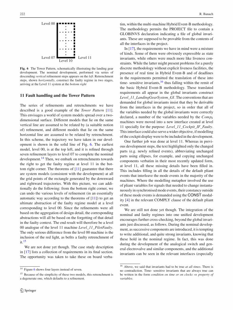
222 R. Banach
Level 00
Level 07 Level 11Level 10
Fig. 6 The Tower Pattern, schematically illustrating the landing geardevelopment. The nominal development, performed via series ofdescending vertical refinement steps appears on the left. Retrenchmentsteps, shown horizontally, construct the faulty regime in two stages,arriving at the Level 11 system at the bottom right
11 Fault handling and the Tower Pattern
The series of refinements and retrenchments we havedescribed is a good example of the Tower Pattern [11].This envisages a world of system models spread over a two-dimensional surface. Different models that lie on the samevertical line are assumed to be related by (a suitable notionof) refinement, and different models that lie on the samehorizontal line are assumed to be related by retrenchment.In this scheme, the trajectory we have taken in our devel-opment is shown in the solid line of Fig. 6. The earliestmodel, level 00, is at the top left, and it is refined throughseven refinement layers to level 07 to complete the nominaldevelopment.14 Then, we embark on retrenchments towardsthe right to get the faulty regime at level 11 in the bot-tom right corner. The theorems of [11] guarantee that thereare system models (consistent with the development) at allthe grid points of the rectangle generated by the downwardand rightward trajectories. With this picture, we can addi-tionally do the following: from the bottom right corner, wecan undo the various levels of refinement (in an essentiallyautomatic way according to the theorems of [11]) to get anultimate abstraction of the faulty regime model at a levelcorresponding to level 00. Since the refinements were allbased on the aggregation of design detail, the correspondingabstractions will all be based on the forgetting of that detailin the faulty context. The end result will therefore be a level00 analogue of the level 11 machine Level_11_PilotFaulty.The only serious difference from the level 00 machine is theinclusion of the red light, as befits a faulty retrenchment ofit.15
We are not done yet though. The case study descriptionin [17] lists a collection of requirements in its final section.The opportunity was taken to take these on board verba-
14 Figure 6 shows four layers instead of seven.15 Because of the simplicity of these two models, this retrenchment isa degenerate one, which defaults to a refinement.
tim, within the multi-machine Hybrid Event-B methodology.The methodology permits the PROJECT file to contain aGLOBINVS declaration indicating a file of global invari-ants. These are supposed to be provable from the contents ofall the interfaces in the project.
In [17], the requirements we have in mind were a mixtureof kinds. Some of them were obviously expressible as stateinvariants, while others were much more like liveness con-straints. While the latter might present problems for a purelydiscrete methodology without explicit liveness facilities, thepresence of real time in Hybrid Event-B and of deadlinesin the requirements permitted the translation of these intotime- sensitive invariants,16 thus falling within the remit ofthe basic Hybrid Event-B methodology. These translatedrequirements all appear in the global invariants constructLevel_11_LandingGearSystem_GI . The conventions that aredemanded for global invariants insist that they be derivablefrom the interfaces in the project, so in order that all ofthe variables needed by the global invariants were correctlydeclared, a number of the variables needed by the Compk
machines were moved into a new interface created at level11 specially for the purpose: Level_11_Cockpit_IF_Faulty.This interface could also serve a wider objective, if modellingof the cockpit display were to be included in the development.
One further job was done at level 11. Whereas in previ-ous development steps, the text highlighted only the changedparts (e.g. newly refined events), abbreviating unchangedparts using ellipses, for example, and copying unchangedcomponents verbatim in their most recently updated form,at level 11, all these missing details have been filled in.This includes filling in all the details of the default pliantevents that interleave the mode events in the majority of themachines. Where the modelling metaphor involved the useof pliant variables for signals that needed to change instanta-neously in synchronised mode events, their constancy outsideof these mode events is demanded using the CONST modal-ity [4] in the relevant COMPLY clause of the default pliantevent.
We are still not done yet though. The integration of thenominal and faulty regimes into one unified developmentencourages further cross-checking, beyond the global invari-ants just discussed, as follows. During the nominal develop-ment, as successive components are introduced, it is temptingto write additional, and quite strong invariants, knowing thatthese hold in the nominal regime. In fact, this was doneduring the development of the analogical switch and gen-eral electrovalve and similar components, and the additionalinvariants can be seen in the relevant interfaces (especially
16 Above, we said that invariants had to be true at all times. There isno contradiction. Time- sensitive invariants that are always true canbe written in the form condition on time or on clocks ⇒ property ofvariables.
123

The landing gear system in multi-machine Hybrid Event-B 223
in Central_IF). In the faulty regime, these invariants nolonger hold, and this fact necessitates the retrenchment ofthe Central_IF and HydraulicCylinders_EV_IF interfaces totheir level 10/11 versions, Central_IF_Faulty and Hydraulic-Cylinders_EV_IF_Faulty. But as long as no fault has beenactivated, these stronger invariants will hold in a run of thesystem. This suggests using the Tower Pattern developmentarchitecture to close the verification loop in the followingway.
It would be quite feasible to mechanise a process, to beapplied to the faulty system as follows: (a) delete/disableall fault injection events from the development; (b) unifyeach interface’s nominal and faulty versions and include theresulting interface in the development;17 (c) then reverifyeverything. Particularly with a variable naming conventionlike the one we have used in this development, in which thesame names are used at successive levels, by doing the pre-ceding, the stronger invariants are made to apply within thefaulty regime, and they will be expected to hold, since thefaulty behaviour has been rendered unreachable.18 In a realis-tic version of this process, the above steps would most likelyneed to be strengthened by additional invariants expressingthe absence of faults, since their unreachability would beimplicit from the point of view of an individual event, whoseguard might still be sensitive to the possibility of faults.
12 The time-triggered loop
A practical implementation of a system like the present onewill ultimately culminate in a time-triggered loop implemen-tation. That is to say, the computing systems will have a timerinterrupt, which will regularly wake them at a predeterminedfrequency, and upon being woken, the timer value, the inter-nal state, and the sensors will all be examined to determinewhat, if anything, needs to happen.
In principle, the events of the level 11 system are fine-grained enough that we would want to see them directlyimplemented in the time-triggered loop system. Two issuesimmediately emerge. The first is relatively trivial, and con-cerns the observation that the time-triggered implementationis typically a sequential program, so that some reconfiguringof the event descriptions may be required to fit this para-digm better, in particular when the events of our ‘ideal’ eventsystem occur sufficiently close in time that they have to beaccommodated in the same polling routine. We regard this asa relatively minor refactoring issue. The second concerns the
17 While the nominal version contains the stronger invariants, the faultyversion contains the references to the abstract variable names, so bothare needed. Furthermore, they are compatible, since the retrenchmentstep just removes the former and adds the latter.18 With different naming conventions, more/different refactoring mightbe needed to achieve this overall effect.
fact that, in a time-triggered loop, events are not executedat exactly the time that the level 11 system would executethem.19 It is the job of this section to explore this.
One rather simple approach is to assume that all eventshappen at some exact multiple of the sampling period. Pro-vided the sampling period is short enough, this is often goodenough from an engineering viewpoint. Then, the behaviourof the implementation is just a subset the behaviours per-mitted by the abstract model, and the latter can simply beviewed as an over-generous safety property. Consequently,the relationship between abstract and implementation modelsbecomes a straightforward refinement, based on an identityretrieve relation (and on the predictability of linearly evolv-ing behaviours for those parts of the system expressed incontinuous terms).
However, in reality, events will not all happen at a multipleof the sampling period, and those assumptions will not hold.The consequence of this is that the abstract model becomes,not a safety property, but a requirement, and the implemen-tation must address all of the behaviours it permits.
Several observations now follow. The first is that only thecomputing systems are modified by the time-triggered imple-mentation. The electromechanical components continue tobehave as before. The second is that because we model han-dle stimuli via events synchronised with the computers (andnot via sensors), we are forced to restrict handle events tooccur at exact multiples of the sampling period.20 The thirdis that regarding the electromechanical components, whenthey are stimulated they behave just as they did before, so nomodelling change is needed there. The fourth is that whenthe electromechanical components attempt to stimulate thecomputer(s), the computer(s) can only react at predeterminedtimes, so that the synchrony of the relevant events in ourdetailed modelling would need to be broken, a delay betweena stimulus and its processing would need to be introduced,and the consequences of that delay would need to be capturedin the formal relationship between abstract and concrete sys-tems. In summary, a system run would now be broken up
19 This is based on the assumption that the specifications of these eventsremain as in the level 11 system, but that the times at which they occurchanges—this also being connected with the issue of whether the pollingfrequency is high enough.20 As a digression, suppose we modelled handle events via sensors.Then, putting aside practicability considerations, in theory, there couldbe an arbitrary number of handle events within a single sampling period.But only the parity of this number would count. If there were an evennumber of events, the situation seen by the computer(s) at the end ofthe sampling period would be the same as before, and the precedingactivity would continue undisturbed. If there were an odd number ofevents, it would be the same as a single handle event, and a new gearmovement activity would be started, or the orientation of the previouslyongoing one would be reversed. Interesting effects might occur if, dueto asynchrony, one computer detected an even number of events and theother computer detected an odd number of events.
123

224 R. Banach
into some events in which the computer(s) stimulated theelectromechanical components, where the timing would beas before, and other events in which the electromechanicalcomponents stimulated the computer(s), but where the reac-tion would be delayed by up to a sampling period.
One popular way of accommodating this kind of disparityin behaviours between abstract and concrete models is theretiming technique [16,20,28]. In this, the concrete model isgiven a more elastic notion of time, so that despite the asyn-chronies caused by time-triggering, corresponding events inthe two models nevertheless occur ‘at the same time’—timeis ‘wiggled a bit’ in the jargon of [20]. Of course, a lot ofdetailed inequalities have to be proved, so that one can besure that unrelated events do not collide with one another, orget put out of temporal or causal order.
In general, the present author is disinclined towards theretiming approach. A time like 3 o’clock should refer to thesame moment in all models in an engineering development.Otherwise, there is a risk of confusion between developers atthe requirements level. In fact, the Hybrid Event-B formalismexplicitly forbids retiming, by insisting that time progressesin exactly the same way in all models of a development chain.Of course, this viewpoint does not make the need for the com-plicated, detailed facts necessitated by the retiming approach,go away. Rather, a better place for them would be a morecomplex refinement retrieve relation, supplemented whereneeded by suitable retrenchment data.
If we apply this perspective to our development, weidentify two different regimes. In the first, the relation-ship between the level 11 and time-triggered systems is aretrieve relation identity. This applies any time the com-puting systems can be said to ‘have the initiative’. Thiscovers the handle events (because, as we said above, han-dle events are synchronised with the computing systems),and those events in which the computing systems issue com-mands to the electromechanical components. In the other,the electromechanical components’ sensors feed back tothe computing systems, with the attendant delays beforeresponse. In the first regime, a retrieve relation that consistsof clauses such as:
condition on time and state variables
⇒ var11 = vart-t (3)
captures what we have been saying above. In this, the 11and t-t superscripts refer to the level 11 and time-triggeredversions of the model variable var, and we need a conjunctionof such terms to make the relationship between level 11 andthe time-triggered system precise.
In the second regime, a retrieve relation that contains manyclauses such as:
condition on time and state variables
⇒(((−−−−−−−−→var11(�t/Δ)
)))
= vart-t(t) (4)
is needed. This says that at any time t, if the relevant condi-tions on the time and on various state variables are satisfied,then the value of the time-triggered variable vart-t will equalthe value of the level 11 variable var11, at a time that corre-sponds to the last sample time �t/Δ, whereΔ is the samplinginterval. The optional overrightarrow selects, on a case bycase basis, whether it is the actual value at �t/Δ itself thatis required, or its left limit.
Clauses like (4) cover variables for which the behaviouris piecewise constant, only. In our case study, we also havelinearly increasing behaviours (for the general electrovalve).For that, the right hand side of (4) must be replaced by a rela-tion between the actual and time-delayed values, accordingto the relevant rate of change. And that is not all. The lin-ear behaviour of the general electrovalve gets cut off at thelowest and highest values, where it remains constant, till theopposite behaviour is required by the analogical switch. Thisrequires clauses that instead of (4), describe the end effectsof these periods of linear behaviour.
If enough effort were invested in identifying all the rele-vant cases, then a refinement could be proved between level11 and the time-triggered system. This would depend on acollection of axioms that enforced relationships between thevarious durations occurring in our development that ensuredthat the different cases just discussed did not ‘crash into eachother’, ruining the refinement. A less exacting collection ofaxioms might only enable a retrenchment to be proved, ratherthan a refinement, and a collection of even weaker axiomsmight not even permit that. Note that in all cases, there maybe many complexities arising from the need to ensure thatfor each variable, there was always at least one clause inthe retrieve relation that enforced the needed relationshipbetween the two models.
What we have discussed is already complicated, andthis was for a situation where piecewise constant behav-iours predominated. Life gets even more complex when wecontemplate situations in which sensors and actuators sendvalues that can vary in more complex and unpredictable ways.The effects of these low-level issues can have a major impacton the stability and predictability of the behaviour of cyber-phyisical systems.
13 Review, modelling patterns, lessons, issues
In the last few sections, we have overviewed the landinggear case study, redone since the Conf treatment in the bynow more fully developed multi-machine Hybrid Event-Bformalism of [10]. The final system in the series of devel-
123
The landing gear system in multi-machine Hybrid Event-B 225
opment steps was the level 11 system, taking into accountthat we did not write out the time-triggered system in full. Inthe level 11 system documentation, we took the additionaltrouble to write out all the details, in contrast to previouslevels, where we concentrated on writing out the changedparts of components while abbreviating unchanged parts, andsimply copied unchanged components from the precedinglevel.
As the development progressed, and it became clear thatcertain techniques worked well to address certain modellingchallenges, the amount of work per step increased. Whilethis can be convenient for human comprehension of thedevelopment process, it can be the enemy of automatic ver-ification, where small steps tend to be much more digestiblefor machines.
To exercise the architectural capabilities of multi-machineHybrid Event-B, we placed each identifiable componentin its own machine. This represents one kind of expres-sivity extreme—each machine was a simple as it couldbe, but it increased the challenge of keeping all thesemachines properly related, while striving to maximise inde-pendent working. At the opposite end of the expressivityspectrum lies the possibility of putting each computer intoa machine, and putting all the physical components intoanother. Conceptually, this would be feasible for the follow-ing reason. Each physical component is designed to haveself-contained physical behaviour. Thus, if its pliant behav-iour were to be captured by a single, universally enabledpliant event (covering all the different behaviours that itmight be required to exhibit in a given application), thenall of these pliant events would be independent, and wouldthus be capable of being conjoined into a single pliantevent.
To illustrate this, suppose the state of apparatus A wasdescribed by pliant variable xA, and its behaviour was spec-ified via the ODE D xA = φA(xA . . .). Likewise supposeapparatus B had state xB , and behaviour given via the ODED xB = φB(xB . . .). We assume that apparatus A and appa-ratus B are independent, so, since engineering in general isdescribed using local realistic theories, φA will not dependon xB and φB will not depend on xA. In such a case,we can put ODE D xA = . . . in a machine for appara-tus A and ODE D xB = . . . in a machine for apparatusB.
But equally easily, we could construct one big machinefor both apparatus A and apparatus B, and describe the jointpliant behaviour via the vector ODE:
[D xA
D xB
]=
[φB(xA . . .)
φB(xB . . .)
]
In fact, semantically, there is no difference. The semantics forthe multiple machine formulation is (behind the scenes) for-
mulated in a global manner, even if the syntactic appearanceis partitioned into multiple machines for the convenience ofdesigners. So a conjoined description is perfectly feasible.
Beyond this, we furthermore note that the mode eventsbelonging to all the different physical components could alsocoexist in the same machine, easily enough. We saw someof the consequences of this in our discussion of the analog-ical switch above, where we stressed the consequences forautomated verification.
13.1 Modelling patterns
In our step-by-step development, we identified a set of use-ful modelling patterns that appeared widely applicable. Wesummarise these now.
P1 The organisation of a development according to thehypergraph architecture proved to be a major advantagein terms of structural clarity. It permitted many complexinvariants to be easily expressed. This gives the conceptvery wide applicability. The notions of type II invariants,and of global invariants in a project, supplements this bymaking different types of cross-cutting invariant avail-able.
P2 The pattern (� j no. of actors in (DLj/stagej)) for variantsthat track progress through, and ensure termination of,some sub-procedure is very general and ought to be morewidely known.
P3 Using a component’s clock as an adjunct to its statemachine proved to be extremely convenient in over-coming the complexities inherent in achieving a safeand transparent design, when safety-sensitive activitieswith extended duration needed to overlap due to tooclose proximity of external stimuli. Modelling mechan-ical safety delays using pure state machine techniqueswould have made the state machines much more cum-bersome, and, importantly, made the design much moreopaque. Simply adjusting the clock to allow a safetymargin of time to elapse before the next required actionproved to be an elegant solution.
P4 In Hybrid Event-B, stimulus and response normally needto be separated temporally. A useful general purposepattern for modelling this has the stimulus event syn-chronised with starting a clock in the response event’smachine. This allows the response event itself to be trig-gered by a timeout or the entry into a time period. Thiskind of modelling permits many different kinds of coop-eration to be expressed.
P5 The introduction of faults in a principled way, startingbottom-up from faults in the lowest level components,and using retrenchment to step back from nominalbehaviour in a stepwise manner, proved to be a useful
123

226 R. Banach
organisational technique for mastering the the complex-ity of faulty system behaviour.
P6 Once faults had been incorporated as in P5, the checkback to nominal behaviour when faults were disabled viathe retrenchment architecture, offered the possibility ofuseful additional confirmation of correct design.
13.2 Issues and questions
As well as these positive outcomes of the exercise, detailedexamination of the issues thrown up by the case studyrevealed a number of areas for further development of theHybrid Event-B framework itself. Among these we can givethe following.
Q1 In contexts in which there is significant use of replicatedcomponents, such as the present one, the availability ofexpressive and flexible indexing techniques for definingcollections of such components is important for expres-sivity and succinctness. In the present development, thiswas addressed by meta level indexing, but it would beneeded in the formal framework in a mature formalism.
Q2 In contexts in which there is significant possibility ofcomponent failure, the rather hardwired synchronisa-tion mechanisms in the present framework can proveinadequate. An example of this occurs when we expecta synchronisation under nominal conditions and yetaccept a partial version if one of the machines has failed.It is fairly clear that the present development has notfully taken on board all the requirements that arise inthis context, for example, when synchronisation is onlyneeded when the last of a set of components that behaveasynchronously has responded.
Q3 A possible contribution to Q2 is to allow events to havemore than one name, e.g. EvName1 ALSO EvName2ALSO EvName3 STATUS . . ., etc. Then, the differentnames of the same event body could appear in differentsynchronisation schemes. This, by itself, is not enoughthough.
Q4 The present development used state variables exclu-sively. It neglected the possibilities made available usingthe I/O semantics of synchronised events. This may leadto certain advantages, and is a possibility that should beexplored.
Q5 The use of clocks as part of the state machine (P3) is veryconvenient but embodies assumptions that only certainthings happen within particular time ranges. Differenttradeoffs between this approach and using more detailedstate machines should be explored, and their pros andcons should be understood.21
21 As an explicit example, consider that in the level 11 model, theanomalyk cases were called on (in principle) quite short timeouts, in
Q6 Although type II invariants were available if needed, thehypergraph architecture rendered them unnecessary inthis development. Is this a general truth or just a fortu-nate property of the present case study? In the oppositedirection, is there a requirement for even more gen-eral, or more complex, cross-cutting invariant patternsin other problem domains?
Q7 Are there ways of further integrating the modelling ofnominal and faulty behaviours, beyond what has beensuggested by the disabling-of-faults technique?
Q8 The most appropriate handling of the implementation ofcomplex event-based systems in terms of time-triggeredsystems raises many questions. Although the essentialmathematical challenges are not novel, the most appro-priate way of packaging the important elements so thatthey can be deployed with the least risk, and maximumengineering benefit, remains as a nontrivial challengefor the future. The simple predominantly piecewise con-stant behaviours of the present development alreadygenerate a number of complex detailed cases, and thesedo not even touch on the additional frequency domainquestions that arise when sensors and actuators have todeal with rapidly varying signals. Reconciling the estab-lished frequency domain techniques with state-basedrefinement frameworks remains as a significant openquestion for future research.
Q9 Of course, doing an exercise like the present one byhand is really tricky—playing the role of a human IDEis extremely error prone. Almost every re-reading ofsome fragment of the development revealed another bug(although typically (and reassuringly), the overwhelm-ing majority of such bugs were of a kind that wouldeasily be picked up mechanically by surface syntacticchecking). Proper machine support is obviously vitalwhen doing such a development in a serious way.
We regard the above questions as outcomes of this study thatare just as valuable as the positive results of the modellingexercise itself.
14 Conclusions
This paper has described the development of the landing gearcase study in the multi-machine Hybrid Event-B framework,as it is defined in [10]. We deliberately approached the devel-opment in a way that would put the formalism under the
Footnote 21 continuedorder not to allow clk_Handlek to overrun into the next nominal event.More finegrained state modelling (as noted earlier) could obviouslyavoid this problem if knowledge of equipment behaviour justified wait-ing longer, in case some physical component responded rather late.
123

The landing gear system in multi-machine Hybrid Event-B 227
maximum stress, so as to identify what worked well, andwhat issues connected with the formalism might warrant fur-ther investigation. We surveyed the resulting good and badpoints in the previous section.
In the earlier part of the work, in the nominal develop-ment where it was legitimate to rely on the perfect workingof all the components, it was easy to specify the requiredbehaviour in a very tightly controlled way. In the B-Methodgenerally, this shows itself as the opportunity to write manyprecise invariants concerning the behaviour. However, whenthe faulty regime is contemplated, the vast majority of thesestronger properties no longer hold, so the intriguing questionarises as to how one can combine the two worlds in a way thatmight be most beneficial for the final delivered system. Oneof the opportunities offered by this case study was the chanceto examine this question in a context that was relatively con-vincing regarding the complexities of a real application.
On this point, the author utilised his established work onretrenchment to try to reconcile the two worlds. Especiallyin the light of the convenient naming convention used in thisdevelopment, it proved possible to reintroduce the strongernominal invariants into a version of the faulty regime whichhad the fault injection mechanism switched off. A practi-cal version of this might well necessitate the inclusion ofadditional axioms/invariants expressing the non-occurrenceof faults, to facilitate the verification process.
To summarise, the landing gear case study has proved tobe an excellent vehicle for significantly exercising the HybridEvent-B framework. Since it was conceived independently ofthe framework, it does not fall into the trap of only includingmodelling issues anticipated to be convenient for the formal-ism, as a case study conceived by the framework’s designersmight have done, even despite their best efforts. All this bodeswell for the development of tool support for the framework.
Open Access This article is distributed under the terms of the CreativeCommons Attribution 4.0 International License (http://creativecommons.org/licenses/by/4.0/), which permits unrestricted use, distribution,and reproduction in any medium, provided you give appropriate creditto the original author(s) and the source, provide a link to the CreativeCommons license, and indicate if changes were made.
References
1. Akers, A., Gassman, M., Smith, R.: Hydraulic Power SystemAnalysis. CRC Press, Boca Raton (2010)
2. Banach, R.: Retrenchment for Event-B: UseCase-wise develop-ment and Rodin integration. Formal Aspects Comput. 23, 113–131(2011)
3. Banach, R.: Landing Gear System Case Study in Hybrid Event-B Web Site (2013). http://www.cs.man.ac.uk/~banach/some.pubs/ABZ2014LandingGearCaseStudy/LandingGearCaseStudy.html
4. Banach, R.: Pliant Modalities in Hybrid Event-B. In: Liu, Z., Wood-cock, J., Zhu, H. (eds.) Theories of Programming and FormalMethods, vol. 8051, pp. 37–53. Springer, Heidelberg (2013)
5. Banach, R.: Invariant guided system decomposition. In: Ait Ameur,Y., Schewe K.-D. (eds.) Abstract State Machines, Alloy, B, TLA,VDM, and Z. LNCS, vol. 8477, pp. 271–276. Springer, Heidelberg(2014)
6. Banach, R.: The landing gear system case study in hybrid Event-B.In: Boniol, F., Weils, V., Ait Ameur, Y., Schewe K.-D. (eds.) ABZ2014: The Landing Gear Case Study. CCIS, vol. 433, pp. 126–141.Springer (2014)
7. Banach, R., Bozzano, M.: The mechanical generation of fault treesfor reactive systems via retrenchment I: combinational circuits.Formal Aspects Comput. 25, 573–607 (2013)
8. Banach, R., Bozzano, M.: The mechanical generation of fault treesfor reactive systems via retrenchment II: clocked and feedbackcircuits. Formal Aspects Comput. 25, 609–657 (2013)
9. Banach, R., Butler, M., Qin, S., Verma, N., Zhu, H.: Core HybridEvent-B I: single Hybrid Event-B machines. Sci. Comput. Pro-gram. 105, 92–123 (2015)
10. Banach, R., Butler, M., Qin, S., Zhu, H.: Core Hybrid Event-BII: Multiple Cooperating Hybrid Event-B Machines (Submitted)(2014)
11. Banach, R., Jeske, C.: Retrenchment and refinement interwork-ing: the Tower theorems. Math. Struct. Comput. Sci. 25, 135–202(2014)
12. Banach, R., Jeske, C., Poppleton, M.: Composition mechanismsfor retrenchment. J. Log. Algebraic Program. 75, 209–229 (2008)
13. Banach, R., Poppleton, M.: Retrenchment: an engineering variationon refinement. In: Bert, D. (ed.) B’98: Recent Advances in theDevelopment and Use of the B Method. LNCS, vol. 1393, pp.129–147. Springer, Heidelberg (1998)
14. Banach, R., Poppleton, M., Jeske, C., Stepney, S.: Engineering andtheoretical underpinnings of retrenchment. Sci. Comput. Program.67, 301–329 (2007)
15. Barolli, L., Takizawa, M., Hussain, F.: Special issue on emergingtrends in cyber-physical systems. J. Ambient Intell. Hum. Comput.2, 249–250 (2011)
16. Beauquier, D., Slissenko, A.: On Semantics of Algorithms withContinuous Time. Tech. Rep. TR-LACL-1997-15, LACL, Univer-sity of Paris-12 (1997)
17. Boniol, F., Wiels, V.: The Landing Gear System Case Study. In:ABZ Case Study, Communications in Computer Information Sci-ence, vol. 433. Springer (2014)
18. Butler, M.: Decomposition structures for Event-B. In: Leuschel,M., Wehrheim, H. (eds.) Integrated Formal Methods. LNCS, vol.5423, pp. 20–38. Springer, Heidelberg (2009)
19. Carloni, L., Passerone, R., Pinto, A., Sangiovanni-Vincentelli, A.:Languages and tools for hybrid systems design. Found. TrendsElectron. Des. Autom. 1, 1–193 (2006)
20. Davoren, J.M.: Epsilon-tubes and generalized skorokhod metricsfor hybrid paths spaces. In: Majumdar, R., Tabuada, P. (eds.) HybridSystems: Computation and Control. LNCS, vol. 5469, pp. 135–149.Springer, Heidelberg (2009)
21. Hallerstede, S., Hoang, T.: Refinement by interface instantiation.In: Derrick, J., Fitzgerald, J., Gnesi, S., Khurshid, S., Leuschel, M.,Reeves, S., Riccobene, E. (eds.) Abstract State Machines, Alloy, B,VDM, and Z. LNCS, vol. 7316, pp. 223–237. Springer, Heidelberg(2012)
22. Ionel, I.: Pumps and Pumping. Elsevier, Amsterdam (1986)23. Jeffords, R., Heitmeyer, C., Archer, M., Leonard, E.: A formal
method for developing provably correct fault-tolerant systemsusing partial refinement and composition. In: Cavalcanti, A., Dams,D.R. (eds.) FM 2009: Formal Methods. LNCS, vol. 5850, pp. 173–189. Springer, Heidelberg (2009)
24. Le Guilly, T., Olsen, P., Ravn, A., Skou, A.: Component reliabilityanalysis. In: Sekerinski (ed.) Proc. FASDS-14, dedicated to KaisaSere. Springer (2014, to appear)
25. Manring, N.: Hydraulic Control Systems. Wiley, New York (2005)
123

228 R. Banach
26. National Science and Technology Council: TrustworthyCyberspace: Strategic plan for the Federal Cybersecurity Researchand Development Program (2011). http://www.whitehouse.gov/sites/default/files/microsites/ostp/fed\_cybersecurity\_rd\_strategic\_plan\_2011.pdf
27. Platzer, A.: Logical Analysis of Hybrid Systems: Proving Theo-rems for Complex Dynamics. Springer, Berlin (2010)
28. Quesel, J.D., Fränzle, M., Damm, W.: Crossing the bridge betweensimilar games. In: Fahrenberg, U., Tripakis, S. (eds.) Formal Mod-eling and Analysis of Timed Systems. LNCS, vol. 6919, pp.160–176. Springer, Heidelberg (2011)
29. Retrenchment Homepage: http://www.cs.man.ac.uk/~banach/retrenchment
30. Silva, R., Pascal, C., Hoang, T., Butler, M.: Decomposition tool forEvent-B. Softw. Pract. Experience 41, 199–208 (2011)
31. Sztipanovits, J.: Model Integration and Cyber Physical Systems:A Semantics Perspective. In: Butler, Schulte (eds.) Proc. FM-11.Springer, LNCS 6664, p. 1 (2011). Invited talk, FM 2011. http://sites.lero.ie/download.aspx?f=Sztipanovits-Keynote.pdf
32. Tabuada, P.: Verification and Control of Hybrid Systems: A Sym-bolic Approach. Springer, Berlin (2009)
33. U.S. Department of Transportation, Federal Aviation Administra-tion, Flight Standards Service: Aviation Maintenance TechnicianHandbook—Airframe (2012). http://www.faa.gov/regulations_policies/handbooks_manuals/aircraft/amt_airframe_handbook/
123


![Landing Gear Accessories - goldlinequalityparts.com€¦ · 12 Landing Gear Accessories Landing Gear Accessories 13 [254.0mm] 10.00" [254.0mm] 10.00" [111.3mm] 4.38" [304.8mm] 12.00"](https://static.fdocuments.in/doc/165x107/5f42201687106b11477aac9b/landing-gear-accessories-12-landing-gear-accessories-landing-gear-accessories.jpg)