The Landing Gear Case Study in Hybrid Event-B
16
The Landing Gear Case Study in Hybrid Event-B Richard Banach School of Computer Science, University of Manchester, Oxford Road, Manchester, M13 9PL, U.K. [email protected] Abstract. A case study problem based on a set of aircraft landing gear is ex- amined in Hybrid Event-B (an extension of Event-B that includes provision for continuously varying behaviour as well as the usual discrete changes of state). Although tool support for Hybrid Event-B is currently lacking, the complexity of the case study provides a valuable challenge for the expressivity and mod- elling capabilities of the formalism. The size of the case study, and in particular, the number of overtly independent subcomponents that the problem domain con- tains, both significantly exercise the multi-machine and coordination capabilities of Hybrid Event-B, requiring the use of novel coordination mechanisms. 1 Introduction This paper reports on a treatment of the landing gear case study using Hybrid Event-B. Hybrid Event-B [4] is an extension of the well known Event-B framework, in which continuously varying state evolution, along with the usual discrete changes of state, is admitted. There is a prima facie case for attempting such an exercise using Hybrid Event-B, since aircraft systems are replete with interactions between physical law and the engineering artifacts that are intended to ensure appropriate aircraft behaviour. In the case of landing gear systems specifically, a good idea of the real complexity of such systems can be gained from Chapter 13 of [16]. Given that landing gear is predominantly controlled by hydraulic systems (see Chap- ter 12 of [16]), it might be imagined that the requirements for the present case study [6], would feature relevant physical properties quite extensively. Hybrid Event-B would be ideally suited to describe the interactions between these and the control system — for example on the basis of the theory and models detailed in [10, 1, 11]. However, it is clear that the requirements in [6] have been heavily slanted to remove such aspects almost completely, presumably because the overwhelming majority of tools in the verification field would not be capable of addressing the requisite continuous aspects. Instead, the relevant properties are reduced to constants (perhaps accompanied by margins of vari- ability) that delimit the duration of various physical processes, these being relevant to a treatment centred on discrete control events. Such an approach reduces the modelling workload, but the penalty paid for it is the loss of the ability to justify the values of these constants during the verification process, whether this be on the basis of deeper theory or of values obtained from lower level phenomenological models. Despite this reservation, a small number of simple continuous behaviours are left within the requirements in [6], these being confined to simple linear behaviours of some
Transcript of The Landing Gear Case Study in Hybrid Event-B

The Landing Gear Case Study in Hybrid Event-B
Richard Banach
School of Computer Science, University of Manchester,Oxford Road, Manchester, M13 9PL, U.K.
Abstract. A case study problem based on a set of aircraft landing gear is ex-amined in Hybrid Event-B (an extension of Event-B that includes provision forcontinuously varying behaviour as well as the usual discrete changes of state).Although tool support for Hybrid Event-B is currently lacking, the complexityof the case study provides a valuable challenge for the expressivity and mod-elling capabilities of the formalism. The size of the case study, and in particular,the number of overtly independent subcomponents that the problem domain con-tains, both significantly exercise the multi-machine and coordination capabilitiesof Hybrid Event-B, requiring the use of novel coordination mechanisms.
1 Introduction
This paper reports on a treatment of the landing gear case study using Hybrid Event-B.Hybrid Event-B [4] is an extension of the well known Event-B framework, in whichcontinuously varying state evolution, along with the usual discrete changes of state,is admitted. There is a prima facie case for attempting such an exercise using HybridEvent-B, since aircraft systems are replete with interactions between physical law andthe engineering artifacts that are intended to ensure appropriate aircraft behaviour. Inthe case of landing gear systems specifically, a good idea of the real complexity of suchsystems can be gained from Chapter 13 of [16].
Given that landing gear is predominantly controlled by hydraulic systems (see Chap-ter 12 of [16]), it might be imagined that the requirements for the present case study [6],would feature relevant physical properties quite extensively. Hybrid Event-B would beideally suited to describe the interactions between these and the control system — forexample on the basis of the theory and models detailed in [10, 1, 11]. However, it is clearthat the requirements in [6] have been heavily slanted to remove such aspects almostcompletely, presumably because the overwhelming majority of tools in the verificationfield would not be capable of addressing the requisite continuous aspects. Instead, therelevant properties are reduced to constants (perhaps accompanied by margins of vari-ability) that delimit the duration of various physical processes, these being relevant toa treatment centred on discrete control events. Such an approach reduces the modellingworkload, but the penalty paid for it is the loss of the ability to justify the values of theseconstants during the verification process, whether this be on the basis of deeper theoryor of values obtained from lower level phenomenological models.
Despite this reservation, a small number of simple continuous behaviours are leftwithin the requirements in [6], these being confined to simple linear behaviours of some
parts of the physical apparatus. Yet, these are enough to demonstrate many essentialcapabilities of the Hybrid Event-B formalism in dealing with continuous phenomenaand their interaction with discrete events.
The reduced workload of the restricted requirements was in fact welcome, sincethe limited resources available for the present work meant that a treatment includingall failure modes could not be included. However, the nominal regime study that ispresented here is sufficient to bring out the main benefits of the approach, and somecomments on the failure cases are included in the latter parts of this paper.
Since there is presently no specific tool support for Hybrid Event-B, our case studyis primarily an exploration of modelling capabilities. As explained below, a major ele-ment of this is the challenge of modelling physically separate components in separatemachines, and of interconnecting all these machines in ways appropriate to the do-main, all supported by relevant invariants. This requires novel machine interconnectionmechanisms, introduced for pure Event-B in [2]. The suitability of proposals for suchmechanisms can only be tested convincingly in the context of independently conceivedsubstantial case studies like this one, so it is gratifying that the mechanisms exercisedhere fare well in the face of the complexities of the given requirements.
The rest of this paper is as follows. Section 2 briefly overviews the landing gearrequirements. Section 3 gives an overview of Hybrid Event-B, while Section 4 coversthe case of multiple machines and our modelling strategy for complex systems. A de-scription of our development appears in Section 5. Section 6 summarises the lessonslearned from this exercise and concludes.
2 Landing Gear Overview
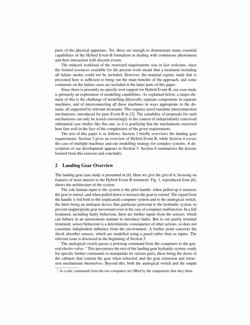
The landing gear case study is presented in [6]. Here we give the gist of it, focusing onfeatures of most interest to the Hybrid Event-B treatment. Fig. 1, reproduced from [6],shows the architecture of the system.
The sole human input to the system is the pilot handle: when pulled up it instructsthe gear to retract, and when pulled down it instructs the gear to extend. The signal fromthe handle is fed both to the (replicated) computer system and to the analogical switch,the latter being an analogue device that gatekeeps powerup to the hydraulic system, toprevent inappropriate gear movement even in the case of computer malfunction. In a fulltreatment, including faulty behaviour, there are further inputs from the sensors, whichcan behave in an autonomous manner to introduce faults. But in our purely nominaltreatment, sensor behaviour is a deterministic consequence of other actions, so does notconstitute independent influence from the environment. A further point concerns theshock absorber sensors, which are modelled using a guard rather than as inputs. Therelevant issue is discussed at the beginning of Section 5.
The analogical switch passes a powerup command from the computers to the gen-eral electro-valve. 1 This pressurises the rest of the landing gear hydraulic system, readyfor specific further commands to manipulate its various parts, these being the doors ofthe cabinets that contain the gear when retracted, and the gear extension and retrac-tion mechanisms themselves. Beyond this, both the analogical switch and the output
1 As a rule, commands from the two computers are ORed by the components that obey them.
4 Frederic Boniol et al.
!"#"$%&'(%)$''
Front door
cylinder
Right door
cylinder
Left door
cylinder
Aircraft hydraulic
circuit
General electro-valve
Electro-valve (close doors)
Electro-valve
(open doors)
Electro-valve (retract gears)
Electro-valve
(extend gears)
Front gear
cylinder
Right gear
cylinder
Left gear
cylinder
Ord
ers
to
ele
ctr
o-v
alv
es
From discrete sensors (gear extended /
not extended, gear retracted / not
retracted, door closed / not closed, door
open / not open, …)
Discrete sensor (pressure OK / not OK)
*(''!+,-'
(retraction
circuit)
(retraction
circuit)
(extension
circuit)
(extension
circuit)
Analogical switch
%)$%)$%)$%)$''%)$%)$''
Towards the
cockpit
Fig. 4. Architecture of the hydraulic part
– One electro-valve that sets pressure on the portion of the hydraulic circuitrelated to door closing.
– One electro-valve that sets pressure on the portion of the hydraulic circuitrelated to landing gear extending.
– One electro-valve that sets pressure on the portion of the hydraulic circuitrelated to the landing gear retracting.
Each electro-valve is activated by an electrical order coming from the digitalpart. In the specific case of the general electro-valve, this electrical order goesthrough an analogical switch in order to prevent abnormal behavior of the digitalpart (e.g. abnormal activation of the general electro-valve).
Note that the three doors (resp. gears) are controlled simultaneously by thesame electro-valve. Put differently, it is not possible to control the doors (resp.gears) separately.
A set of discrete sensors inform the digital part about the state of the equip-ments:
Fig. 1. Architectural overview of the landing gear system, reproduced from [6].
of the general electro-valve are monitored by (triplicated) sensors that feed back to thecomputer systems, as is discernible from Fig. 1.2
What is particularly interesting about the system so far, is that the arrangement ofthese various interconnections between system components is evidently quite far fromthe kind of tree shape that facilitates clean system decomposition. Thus, the handle isconnected to the computers, and the handle is connected to the analogical switch. Butthe analogical switch is also connected to the computers, so ‘dividing’ the computersfrom the analogical switch in the hope of ‘conquering’ structural complexity will notwork, and obstructs the clean separation of proofs into independent subproofs concern-ing analogical switch and computers separately. This poses a major challenge for ourmodelling methodology, and gave rise to the need for new interconnection mechanisms,discussed in Section 4.
Beneath the level of the general electro-valve, it is a lot easier to see the system ascomprised of the computers on the one hand, and the remaining hydraulic componentson the other, connected together in ways that are tractable when the new interconnectionmechanisms are available.
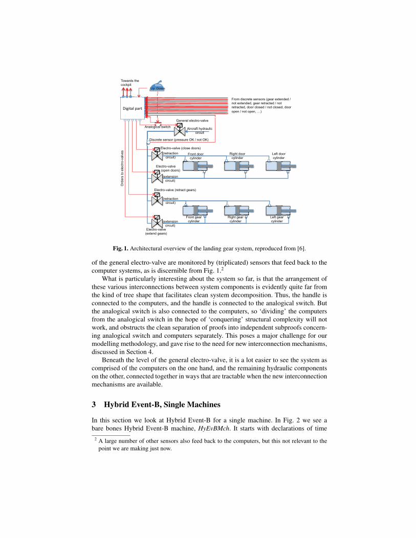
3 Hybrid Event-B, Single Machines
In this section we look at Hybrid Event-B for a single machine. In Fig. 2 we see abare bones Hybrid Event-B machine, HyEvBMch. It starts with declarations of time
2 A large number of other sensors also feed back to the computers, but this not relevant to thepoint we are making just now.
MACHINE HyEvBMchTIME tCLOCK clkPLIANT x, yVARIABLES uINVARIANTS
x, y, u ∈ R,R,NEVENTS
INITIALISATIONSTATUS ordinaryWHEN
t = 0THEN
clk, x, y, u := 1, x0, y0, u0END
. . . . . .
. . . . . .MoEv
STATUS ordinaryANY i?, l, o!WHERE
grd(x, y, u, i?, l, t, clk)THEN
x, y, u, clk, o! :|BApred(x, y, u, i?, l, o!,t, clk, x′, y′, u′, clk′)
END. . . . . .
. . . . . .PliEv
STATUS pliantINIT iv(x, y, t, clk)WHERE grd(u)ANY i?, l, o!COMPLY
BDApred(x, y, u,i?, l, o!, t, clk)
SOLVED x =φ(x, y, u, i?, l, o!, t, clk)
y, o! :=E(x, u, i?, l, t, clk)
ENDEND
Fig. 2. A schematic Hybrid Event-B machine.
and of a clock. In Hybrid Event-B, time is a first class citizen in that all variables arefunctions of time, whether explicitly or implicitly. However time is special, being read-only. Clocks allow more flexibility, since they are assumed to increase like time, butmay be set during mode events (see below). Variables are of two kinds. There are modevariables (like u) which take their values in discrete sets and change their values viadiscontinuous assignment in mode events. There are also pliant variables (such as x, y),declared in the PLIANT clause, which typically take their values in topologically densesets (normally R) and which are allowed to change continuously, such change beingspecified via pliant events (see below).
Next are the invariants. These resemble invariants in discrete Event-B, in that thetypes of the variables are asserted to be the sets from which the variables’ values at anygiven moment of time are drawn. More complex invariants are similarly predicates thatare required to hold at all moments of time during a run.
Then, the events. The INITIALISATION has a guard that synchronises time with thestart of any run, while all other variables are assigned their initial values as usual.
Mode events are direct analogues of events in discrete Event-B. They can assign allmachine variables (except time itself). In the schematic MoEv of Fig. 2, we see threeparameters i?, l, o!, (an input, a local parameter, and an output respectively), and a guardgrd which can depend on all the machine variables. We also see the generic after-valueassignment specified by the before-after predicate BApred, which can specify how theafter-values of all variables (except time, inputs and locals) are to be determined.
Pliant events are new. They specify the continuous evolution of the pliant variablesover an interval of time. The schematic pliant event PliEv of Fig. 2 shows the struc-ture. There are two guards: there is iv, for specifying enabling conditions on the pliantvariables, clocks, and time; and there is grd, for specifying enabling conditions on themode variables. The separation between the two is motivated by considerations con-nected with refinement.
The body of a pliant event contains three parameters i?, l, o!, (again an input, a localparameter, and an output) which are functions of time, defined over the duration of thepliant event. The behaviour of the event is defined by the COMPLY and SOLVE clauses.The SOLVE clause specifies behaviour fairly directly. For example the behaviour ofpliant variable y and output o! is given by a direct assignment to the (time dependent)
value of the expression E(. . .). Alternatively, the behaviour of pliant variable x is givenby the solution of the first order ordinary differential equation (ODE) D x = φ(. . .),where D indicates differentiation with respect to time. (In fact the semantics of they, o! = E case is given in terms of the ODE D y,D o! = D E, so that x, y and o!satisfy the same regularity properties.) The COMPLY clause can be used to express anyadditional constraints that are required to hold during the pliant event via its before-during-and-after predicate BDApred. Typically, constraints on the permitted range ofvalues for the pliant variables, and similar restrictions, can be placed here.
The COMPLY clause has another purpose. When specifying at an abstract level,we do not necessarily want to be concerned with all the details of the dynamics — itis often sufficient to require some global constraints to hold which express the neededsafety properties of the system. The COMPLY clauses of the machine’s pliant eventscan house such constraints directly, leaving it to lower level refinements to add thenecessary details of the dynamics.
Briefly, the semantics of a Hybrid Event-B machine is as follows. It consists of a setof system traces, each of which is a collection of functions of time, expressing the valueof each machine variable over the duration of a system run. (In the case of HyEvBMch,in a given system trace, there would be functions for clk, x, y, u, each defined over theduration of the run.)
Time is modeled as an interval T of the reals. A run starts at some initial mo-ment of time, t0 say, and lasts either for a finite time, or indefinitely. The durationof the run T , breaks up into a succession of left-closed right-open subintervals: T =[t0 . . . t1), [t1 . . . t2), [t2 . . . t3), . . .. The idea is that mode events (with their discontinu-ous updates) take place at the isolated times corresponding to the common endpointsof these subintervals ti, and in between, the mode variables are constant and the pliantevents stipulate continuous change in the pliant variables.
Although pliant variables change continuously (except perhaps at the ti), continuityalone still admits a wide range of mathematically pathological behaviours. To eliminatethese, we insist that on every subinterval [ti . . . ti+1) the behaviour is governed by awell posed initial value problem D xs = φ(xs . . .) (where xs is a relevant tuple of pliantvariables and D is the time derivative). ‘Well posed’ means that φ(xs . . .) has Lipschitzconstants which are uniformly bounded over [ti . . . ti+1) bounding its variation with re-spect to xs, and that φ(xs . . .) is measurable in t. Moreover, the permitted discontinuitiesat the boundary points ti enable an easy interpretation of mode events that happen at ti.
The differentiability condition guarantees that from a specific starting point, ti say,there is a maximal right open interval, specified by tMAX say, such that a solution to theODE system exists in [ti . . . tMAX). Within this interval, we seek the earliest time ti+1
at which a mode event becomes enabled, and this time becomes the preemption pointbeyond which the solution to the ODE system is abandoned, and the next solution issought after the completion of the mode event.
In this manner, assuming that the INITIALISATION event has achieved a suitableinitial assignment to variables, a system run is well formed, and thus belongs to thesemantics of the machine, provided that at runtime:
• Every enabled mode event is feasible, i.e. has an after-state, and on its comple-tion enables a pliant event (but does not enable any mode event).3
(1)
• Every enabled pliant event is feasible, i.e. has a time-indexed family of after-states, and EITHER:
(i) During the run of the pliant event a mode event becomes enabled. It pre-empts the pliant event, defining its end. ORELSE
(ii) During the run of the pliant event it becomes infeasible: finite termination.ORELSE
(iii) The pliant event continues indefinitely: nontermination.
(2)
Thus in a well formed run mode events alternate with pliant events. The last event(if there is one) is a pliant event (whose duration may be finite or infinite). In reality,there are a number of semantic issues that we have glossed over in the framework justsketched. We refer to [4] for a more detailed presentation.
We point out that the presented framework is quite close to the modern formulationof hybrid systems. See eg. [15, 12] for representative modern formulations, or [8] for aperspective stretching further back.
4 Top-Down Modelling of Complex Systems, and MultipleCooperating Hybrid Event-B Machines
The principal objective in modelling complex systems in the B-Method is to start withsmall simple descriptions and to refine to richer, more detailed ones. This means that, atthe highest levels of abstraction, the modelling must abstract away from concurrency.By contrast, at lower levels of abstraction, the events describing detailed individualbehaviours of components become visible. In a purely discrete event framework, likeconventional Event-B, there can be some leeway in deciding whether to hold all theselow level events in a single machine or in multiple machines — because all eventsexecute instantaneously, isolated from one another in time (in the usual interpretation).
In Hybrid Event-B the issue is more pressing. Because of the continuous behaviourthat is represented, all components are always executing some event. Thus an inte-grated representation risks hitting the combinatorial explosion of needing to representeach possible combination of concurrent activities within a separate event, and there isa much stronger incentive to put each (relatively) independent component into its ownmachine, synchronised appropriately. Put another way, there is a very strong incentiveto not abstract away from concurrency, an impulse that reflects the actual system ar-chitecture. In Hybrid Event-B, there is thus an even greater motivation than usual for therefinement methodology to make the step from monolithic to concurrent convincingly.
This is accomplished by using normal Hybrid Event-B refinement up to the pointwhere a machine is large enough and detailed enough to merit being split up. Then, thekey concept in the decomposition is the INTERFACE. This is adapted from the idea in[9] to include not only declarations of variables, but of the invariants that involve them,and their initialisations. A community of machines may have access to the variablesdeclared in an interface if each machine CONNECTS to the interface. All events in the
3 If a mode event has an input, the semantics assumes that its value only arrives at a time strictlylater than the previous mode event, ensuring part of (1) automatically.
INTERFACE Level7 AnSw IFREADS Level7 Comp IFREFERS Level7 Comp IFCLOCK clk AnSwVARIABLES
AnSwClosed, sens AnSwiPLIANT
answ2genevINVARIANTS
AnSwClosed ∈ BOOLansw2genev ∈ BOOL(AnSw CLOSED INIT < clk AnSw <
AnSw CLOSED FIN)⇒ AnSwClosed¬(AnSw CLOSED INIT ≤ clk AnSw ≤
AnSw CLOSED FIN)⇒ ¬AnSwClosed. . . . . . . . . . . .
. . . . . . . . . . . ./\/\/\i sens AnSwi ∈ {OPEN,CLOSED}/\/\/\i AnSwClosed ⇒ sens AnSwi = CLOSED/\/\/\i ¬AnSwClosed ⇒ sens AnSwi = OPENansw2genev⇒ cmp2answ1 ∨ cmp2answ2answ2genev⇒ AnSwClosed
INITIALISATIONBEGIN
clk AnSw := BIGTAnSwClosed := FALSE||i sens AnSwi := OPENansw2genev := FALSE
ENDEND
Fig. 3. Level 7 interface for the analogical switch, from the case study.
machines must preserve all of the invariants in the interface, of course. An importantpoint is that all invariants involving the interface’s variables must be in the interface.
Well, not quite all; an exception is needed. Invariants of the form U(u) ⇒ V(v),where variables u and v belong to different interfaces, are also allowed. Such cross-cutting invariants (which we call type 2 invariants, t2i s) are needed to express fun-damental dependencies between subsystems which are coupled in a nontrivial manner(such couplings invariably arise in multicomponent systems). In a t2i, the u and v vari-ables are called the local and remote variables respectively. By convention a t2i residesin the interface containing its local variables.
Fig. 3 shows an example of the preceding taken from the landing gear case study. Itis an interface, Level7 AnSw IF, primarily intended for some variables of the AnalogicalSwitch. It contains some, by now, familiar ingredients, such as a clock clk AnSw, andsome mode and pliant variables, AnSwClosed, sens AnSwi, answ2genev. These modelthe state of the analogical switch, the state of its sensors, and the signal from the switchto the general electro-valve. It also contains statements READS Level7 Comp IF andREFERS Level7 Comp IF.
The first of these says that the interface contains a t2i (specifically answ2genev ⇒cmp2answ1 ∨ cmp2answ2) for which the local variables (i.e. answ2genev) are found inLevel7 AnSw IF, and the remote variables (i.e. cmp2answ1, cmp2answ2) are found inLevel7 Comp IF, which is another interface, predominantly concerned with variables(and their invariants) belonging to the computer systems.
The second expresses the converse idea, namely that there is a t2i in Level7 Comp IFfor which the local variables are in Level7 Comp IF, and the remote variables are inLevel7 AnSw IF.
By restricting to t2is as the only means of writing invariants that cross-cut across twointerfaces (and, implicitly, across the machines that access them), we can systematise,and then mechanise, the verification of such invariants. Thus, for a t2i U(u) ⇒ V(v)it is sufficient for events that update the u variables to preserve ¬U (if it is true in thebefore-state) and for events that update the v variables to preserve V (if it is true inthe before-state). A more comprehensive treatment of the notion of interface used hereappears in [2].
As well as sharing variables via interfaces, multi-machine Hybrid Event-B systemsneed a synchronisation mechanism — one that is more convenient than creating such athing ab initio from the semantics. For this the shared event paradigm [7, 14] turns outto be the most convenient. In this scheme, identically named (mode) events in two (ormore) machines of the system are deemed to be required to execute simultaneously. Inpractice, it means that for each such event, its guard is re-interpreted as the conjunctionof the guards of all the identically named events. Below, in Section 6, we say rathermore more about mode event synchronisation. In particular, we point out the need fora more flexible method of identifying events which are to be synchronised than purename identity. (In fact, a more flexible mechanism has been implemented in the RodinTool [13] than is described in the literature. However, we stick, for simplicity and com-parability with the published literature, to the simple and static identical name scheme.)
5 Model Development
Having discussed the technical preliminaries, in this section, we overview the devel-opment of the landing gear case study. To clarify some minor inconsistencies in thespec [6], we assume that the pilot controls the gear via a handle for which handle UPmeans gear up, and handle DOWN means gear down. We also assume that in the initialstate the gear is down and locked, since the aircraft does not levitate when stationaryon the ground, presumably. Connected with this requirements aspect is the absence ofprovision in [6] of what is to happen if the pilot tries to pull the handle up when theaircraft is not in flight. Presumably the aircraft should not belly-flop to the ground, sowe just incorporate a suitable guard on the handle movement events, based on the valueof the shock absorber sensors. This leaves open the question of what actually happensif the pilot pulls the handle up when the plane is on the ground. Does the handle resistthe movement, or does gear movement remain pending until released by the state of theshock absorber sensors, or ...?
This issue, in turn, raises a further interesting question. Although the fact just pointedout causes no special problem for an event-by-event verification strategy like the B-Method, the absence of any explicit requirement that allows the shock absorber tochange value, would be equivalent to the aircraft never leaving the ground, leading tothe absence of nontrivial traces for a trace based verification strategy to work on (unlesssuitable additional events were introduced into the model, just for this purpose).
Pursuing the technical strategy discussed earlier, implies that in the final develop-ment, each component that is identifiable as a separate component in the architecturalmodel, should correspond to a machine in its own right. Thus, at least, the pilot subsys-tem (handle and lights), the two computers, the analogical switch, the general electro-valve, and the individual movement electro-valves (and their associated hydraulic cylin-ders), should all correspond to separate machines at the lowest level of development.The nontrivial interdependencies between these subsystems give rise to enough cross-cutting type 2 invariants between the corresponding machines to thoroughly exercisethe modelling capabilities of our formal framework.
A further technical goal in this development is, as far as possible, to use variablesthat correspond directly to quantities discussed in the requirements document. The aim
is to strive for the closest possible correspondence between requirements and formalmodel, in the belief that this improves the engineering process. Allied to this is the factthat the present work is the most complex case study attempted in Hybrid Event-B todate, so, a certain amount of experimentation was carried out during the case studyin order to evaluate different modelling approaches to various features found in [6].Consequently, the same kind of situation is not always approached in the same way.
5.1 The Nominal Regime
With these remarks made, we turn to the development itself. This is too big to includein full here of course; the details can be found at [3]. In this section we summarise theessentials, pausing to discuss interesting issues as they arise.
We focus on the nominal regime. For the faulty regime, see below. Adhering to thevision of the B-Method, the development starts very simply, and proceeds to add detailvia layers of refinement. As different parts of the system require different numbers ofrefinement steps in order to reach their final degree of detail, in [3], the various syn-tactic constructs are labeled with a level number, and the caption accompanying eachconstruct states which constructs constitute the system at the current level of develop-ment.
Level 0 gives the simplest, pilot-level view of the system, and consists of just onemachine: Level0 PilotAndLightsNominal. There are mode events for raising and lower-ing the handle, and for switching the green and orange lights on and off (the red light isignored in the nominal regime). For example:
PilotGearUPANY in?WHERE in? = pilotGearUP X ∧ handle = DOWNTHEN handle := UPEND
This is identical to normal Event-B, aside from the input parameter in?, which is re-quired to be pilotGearUP X, and which is furthermore unused in the event. The expla-nation for this is that while in normal Event-B, events are assumed to execute lazily,i.e. not at the very instant they become enabled (according to the normal interpretationof how event occurrences map to real time), in Hybrid Event-B, mode events executeeagerly, i.e. as soon as they are enabled (in real time).
This is because physical law is similarly eager: if a classical physical system reachesa state in which some transition is enabled, it is overwhelmingly the case that energeticsand thermodynamics force the transition to take place straight away. Hybrid Event-B,in being designed to model physical systems, must therefore conform to this. As aconsequence, typical Event-B models, in which a new after-state immediately enablesthe next transition, would cause an avalanche of mode event occurrences if interpretedaccording to Hybrid Event-B semantics.
To avoid this, and yet to allow modelling convenience in Hybrid Event-B, the unde-sirable avalanche of mode event occurrences is avoided at runtime by building a delayinto the semantics. The delay lasts as long as a required input parameter remains absent,and the semantics assumes that the input does not arrive until after some positive (butotherwise unspecified — unless more precisely constrained in the guard) period of timehas elapsed.
There is also a default pliant event PliTrue to define behaviour between occurrencesof the mode events. It merely stipulates COMPLY INVARIANTS.
Level 1 is a simple refinement of level 0, and just introduces some additional vari-ables. Aside from minor details of syntax, it is just a discrete Event-B refinement ofLevel0 PilotAndLightsNominal to Level1 PilotAndLightsNominal.
Level 2 begins the process of splitting things into smaller components. The level1 machine is split into Level2 PilotNominal and Level2 CompNominal. Each event ofLevel1 PilotAndLightsNominal is split into a pair of synchronised events in the twomachines. The former reflects the pilot’s view, in which the pilot is responsible for han-dle events (so the earlier in? = pilotGearUP X goes into the Pilot machine), and thecomputer is responsible for the lights events (so the inputs for those events go into theComp machine). The rationale for the latter is that the occurrences of the lights eventsdepend on as yet absent Comp details, so at this level of abstraction, they just appear asspontaneously generated events from Comp’s environment, to be eventually refined tothe deterministic behaviour of a more complete computing machine. The relationshipbetween Level2 PilotNominal and Level2 CompNominal is mediated by an interface,Level2 Comp IF, which contains all the variables shared by the two machines. Thedecomposition of the level 1 machine into the two level 2 machines plus their inter-face constitutes a ‘textbook’ example of doing decomposition according to the schemedescribed earlier.
The next few levels are concerned with reconciling the pilot’s view of a singularcomputing system behaviour with the reality of the duplicated computing modules ofthe architecture of Fig. 1. Again, while the system description is still small, a ‘text-book’ approach to the issue is taken. What we mean by this is that there will be amachine depicting a singular computing system behaviour for the pilot, connected withtwo actual computing modules which will be successively refined to include further im-plementation detail. The textbook approach to this is to refine the Level2 CompNominalmachine to a machine, Level3 CompNominal that: firstly, duplicates the computer initi-ated events (to model potential asynchrony of the two computing modules4); secondly,replicates the relevant variables so that each representative machine will have its owncopy of each relevant variable. This situation is supported by an enriched interfaceLevel3 Comp IF. That done, at level 4, we can decompose Level3 CompNominal intoLevel4 CompNominal (expressing the pilot’s view), and Level4 Comp1Nominal andLevel4 Comp2Nominal (the two ‘real’ computing modules-to-be).
The main outcome of this approach is to convince us of its extreme verbosity as away of modelling the ‘OR’ of the two computing modules’ commands whenever theymust send a command to any external component. In the remainder of the development,such verbosity is avoided by having the receiving component simply react to the OR ofthe received signals in the guards of its events, even though this is slightly inaccuratearchitecturally (since, in reality, the OR is calculated outside the relevant component).
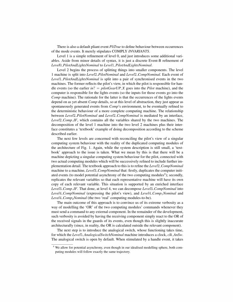
The next step is to introduce the analogical switch, whose functioning takes time,for which the Level5 AnalogicalSwitchNominal machine introduces a clock, clk AnSw.The analogical switch is open by default. When stimulated by a handle event, it takes
4 We allow for potential asynchrony, even though in our idealised modelling sphere, both com-puting modules will follow exactly the same trajectory.
CLOSED_INIT CLOSED_FIN OPEN0
• • • ••
clk_AnSw
0
•• •
•
•
clk_Handle
Gear Extend
Gear Retract
Door CloseDoor Open
• •
Gear Start Moving Gear Stop Moving
Fig. 4. The analogical switch machine’s transitions when interrupted by a fresh handle event.
some time to close (from 0 till CLOSED INIT), then stays closed for a while (fromCLOSED INIT till CLOSED FIN), then takes some time to open once more (fromCLOSED FIN till OPEN). Fig. 4 indicates what happens to the clock value when afresh handle event occurs before the previous sequence has completed. The handleevents that intiate these activities are synchronised with the pilot’s handle events (inmachine Level5 PilotNominal, which is a copy of Level2 PilotNominal but includingthese additional synchronisations). This in order to model the fact that —according tothe architecture of Fig. 1— the pilot’s handle events reach the analogical switch directly,and not via the computing modules.
Thus far, the development is relatively tree-shaped. Practically speaking, this meansthat there is no need for nontrivial invariants involving variables that are not declared inthe same place. For a development of modest size, it is always possible to arrange thingsso that this holds. However, as the size of the development increases, the prescienceneeded to arrange the development so that this remains true, and the need to appropri-ately separate concerns, both render this desire unrealistic. We see this in concrete termsin our development at level 6, which is concerned with introducing the analogical switchsensors. For clarity, these are introduced in a separate step to that which introduces theanalogical switch itself. Since the analogical switch is by now in a separate machinefrom the computing modules, any invariant involving the sensors and computing vari-ables becomes a cross-cutting t2i. This applies to /\/\/\i gearsMovingk ⇒ sens AnSwi =CLOSED which states that various landing gears do not start moving until the theanalogical switch is sensed to be closed. This t2i appears in the Level6 Comp IF in-terface, using the t2i machinery discussed above. This necessitates a partitioning ofLevel5 AnalogicalSwitchNominal in that a new interface, Level6 AnSw IF is needed tohouse some of the Level5 AnalogicalSwitchNominal variables, so as to conform to thesyntactic conventions for t2is, yielding also machines Level6 AnalogicalSwitchNominaland Level6 CompkNominal.
A similar process can be followed for introducing the general electro-valve. Thisis carried out at level 7, rather as for the analogical switch at level 5. What is interest-ing though, for the general electro-valve, is that the requirements [6] do specify somecontinuous behaviour for this component, albeit that this is simple linear behaviour.The opportunity is taken here to model this using nontrivial pliant events in machineLevel7 General EV Nominal. For instance, the growth of pressure in the door and gearmovement circuits is given by:
PressureIncreasingOrHIGHINIT answ2genevSOLVE
D genEVoutput = PressureIncRate× bool2real((genEVoutput < HIGH) ∧ answ2genev)END
This says that the time derivative of genEVoutput is constant as long as genEVoutput

does not exceed HIGH and the control signal answ2genev is true. Once genEVoutput =HIGH is reached, the derivative drops to zero and so genEVoutput remains constant.
Level 8, which introduces the sensors for the general electro-valve, is as interestingas level 7. The general electro-valve sensors only signal HIGH when genEVoutput ac-tually reaches HIGH. This leads to a multi-step refinement of the level 7 pliant eventPressureIncreasingOrHIGH. A first pliant event models the increasing episode duringwhich the derivative is nonzero, and a second pliant event models the constant episodeduring which genEVoutput remains at HIGH. The two pliant events are separated bya mode event PressureHIGH reached, that turns the sensors to HIGH. A similar stateof affairs holds for the pressure decreasing regime, when the answ2genev signal goesfalse.
Even more interesting is the fact that due to pilot initiated handle events, the ana-logical switch’s behaviour may be restarted before a previous behaviour has completed,leading to two possible mode events in the general electro-valve that synchronise withthe analogical switch closure event: one for the normal case when the general electro-valve is depressured AnSw CLOSED INIT reached 1 S, and another for when it is al-ready pressured-up AnSw CLOSED INIT reached 2 S.
And even more interesting than that, is the fact that the timing of pilot initiated han-dle events may be such that mode event AnSw CLOSED INIT reached 2 S is sched-uled to occur at exactly the same moment as the mode event that naturally separates theincreasing and HIGH episodes in the general electro-valve, PressureHIGH reached.The guards and actions of the two mode events are identical, which would cause trou-ble with respect to the semantics, were it not for the fact that one of the mode events isa synchronised event and the other is not.
Normally, the unproductive complications of such coincidences in the semanticsare avoided in Hybrid Event-B by assuming in the semantics that inputs do not arriveat times which clash with other mode events (see the earlier discussion in Section 4).But the case we are discussing is not like this since the coincidence occurs as a conse-quence of an earlier mode event that is quite innocent. Clearly such coincidences are notstatically computable in general, so cannot be avoided by some kind of static definitionin the semantics. Then, rather than complicate the modelling as we have done in thepresent case study, a possible way forward is as follows.
During design and development, we neglect the possible existence of these issues ofundesired coincidence of mode events. In an environment with proper tool support forHybrid Event-B, the potential coincidences will invariably generate some unprovablenecessary conditions for semantic soundness. These conditions can then be added asfurther hypotheses in a domain theory, leading to closure of the previously open proofs.Provided such conditions only occupy a portion of the parameter space that is of zeromeasure, no harm would be done to any practical implementation, since no practicalimplementation that behaves in a stable way can hit a portion of the parameter space ofzero measure.
We proceed to level 9. Now that the general electro-valve can be powered up anddown, this level introduces the individual movement electro-valves, and implicitly, thehydraulic cylinders that they manipulate. Each of the four movement electro-valves andcylinders gives rise to a new machine. Also there is Level9 HydraulicCylinders EV IF,

CLOSED_INIT CLOSED_FIN OPEN0
• • • ••
clk_AnSw
0
•• •
•
•
clk_Handle
Gear Extend
Gear Retract
Door CloseDoor Open
• •
Gear Start Moving Gear Stop Moving
Fig. 5. The approximate timing diagram for the level 10 computing machine.
a new interface that links them all to the computing modules. New synchronised eventsin the computing modules and electro-valve/cylinder machines command the initia-tion of the operation of the movement hydraulic cylinders, and timed events monitorthe completion of the relevant operations via the relevant battery of sensors, given thevariability in completion time described in [6]. All four operations are similar, so onlyone has been modelled in detail in [3]. The cross-cutting t2is that couple variables inLevel9 HydraulicCylinders EV IF to those in the computing interface Level9 Comp IFare handled in the by now familiar way.
Up to now, the impetus for executing any particular event that is potentially availablein a machine has come from the environment, via the technique of using an externalinput that is created for that sole purpose. (Where there are synchronised families ofevents, one of them is allocated the external input and the rest are synchronised with it.)The final step in modelling the nominal regime is to remove this artifice, and replaceit with explicit timing constraints. This is the job of level 10. Note that explicit timinginformation is already included in subsystems for which the description is relativelycomplete, such as the analogical switch, and the the general and movement electro-valves, so this development step only concerns the computing modules.
It was tempting to try to introduce the computing module timing constraints in astep by step fashion. However, it was soon realised that the complexity and intercon-nectedness of the constraints was such that a stepwise approach would need to allowguard weakening as well as guard strengthening. Since Event-B is not geared for guardweakening, the idea was abandoned in favour of a monolithic approach that introducedall of the timing machinery in one go.
Fig. 5 outlines the behaviour of the computing module’s clock clk Handle, whenthe handle is manipulated during the course of gear extending or retracting. UnlikeFig. 4 though, where the behaviour illustrated is close to what the model describes(since the analogical switch just responds to handle events in a self-contained way),Fig. 5 neglects important detail. For example, consider a PilotGearUP S event whilethe gear is extending. Then, the retracting sequence has to be executed but only fromthe point that extending has reached. So first, clk Handle is changed to stop the gearextending command. Then, clk Handle is changed to a time sufficiently before the gearretracting command time that hydraulic hammer5 has subsided. Once it is safe to acti-
5 Hydraulic hammer is the term for the collection of transient shock waves that propagate roundthe hydraulic system when relatively abrupt changes are inflicted on its control surfaces (i.e. the
vate the gear retracting command, the gear retracting command is activated, and thenclk Handle is changed again to advance the clock in proportion to the undone part ofthe gear extending activity. In effect, we use clk Handle intervals as part of the statemachine controlling the behaviour of the computing modules (along with additional in-ternal variables). This proves especially convenient when the state transitions involvedconcern delays between commands that need to be enforced in order to assure mechan-ical safety (e.g. the hydraulic hammer case, just discussed). Such details are not visiblein Fig. 5, but make the design of the level 10 events quite complicated. This completesour development of the nominal regime.
5.2 The Faulty Regime and the Imperative Closed Loop(a) (b)
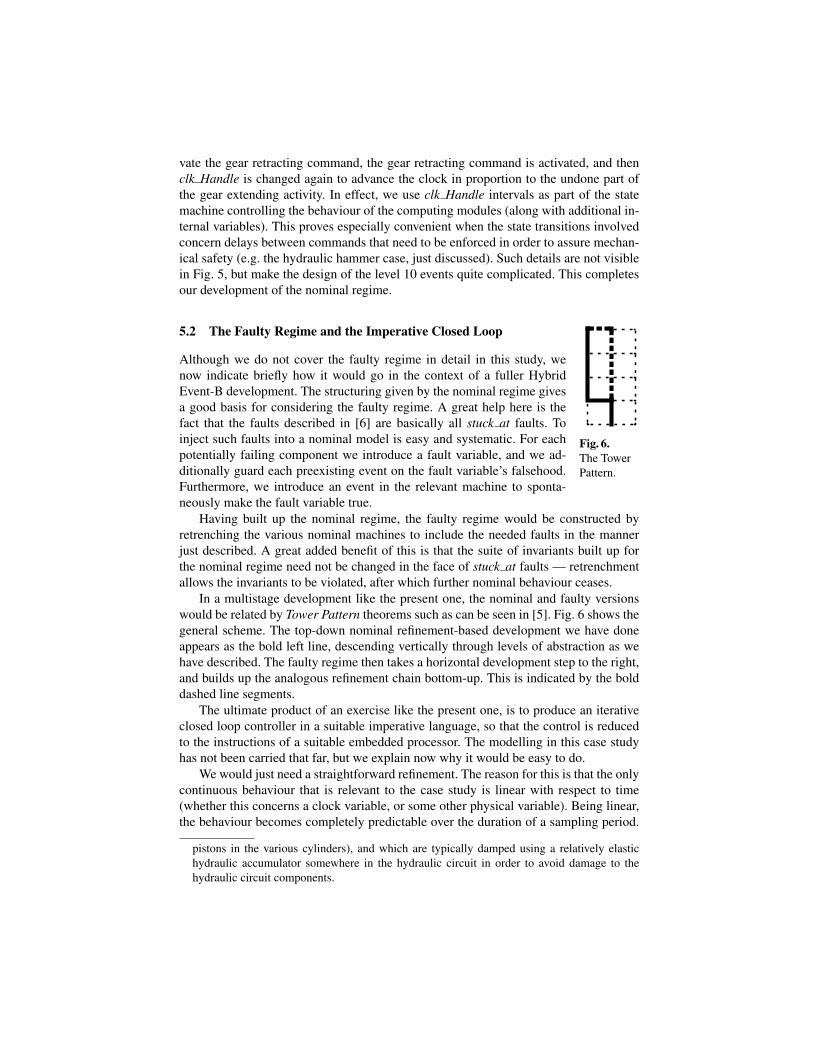
Fig. 6.The TowerPattern.
Although we do not cover the faulty regime in detail in this study, wenow indicate briefly how it would go in the context of a fuller HybridEvent-B development. The structuring given by the nominal regime givesa good basis for considering the faulty regime. A great help here is thefact that the faults described in [6] are basically all stuck at faults. Toinject such faults into a nominal model is easy and systematic. For eachpotentially failing component we introduce a fault variable, and we ad-ditionally guard each preexisting event on the fault variable’s falsehood.Furthermore, we introduce an event in the relevant machine to sponta-neously make the fault variable true.
Having built up the nominal regime, the faulty regime would be constructed byretrenching the various nominal machines to include the needed faults in the mannerjust described. A great added benefit of this is that the suite of invariants built up forthe nominal regime need not be changed in the face of stuck at faults — retrenchmentallows the invariants to be violated, after which further nominal behaviour ceases.
In a multistage development like the present one, the nominal and faulty versionswould be related by Tower Pattern theorems such as can be seen in [5]. Fig. 6 shows thegeneral scheme. The top-down nominal refinement-based development we have doneappears as the bold left line, descending vertically through levels of abstraction as wehave described. The faulty regime then takes a horizontal development step to the right,and builds up the analogous refinement chain bottom-up. This is indicated by the bolddashed line segments.
The ultimate product of an exercise like the present one, is to produce an iterativeclosed loop controller in a suitable imperative language, so that the control is reducedto the instructions of a suitable embedded processor. The modelling in this case studyhas not been carried that far, but we explain now why it would be easy to do.
We would just need a straightforward refinement. The reason for this is that the onlycontinuous behaviour that is relevant to the case study is linear with respect to time(whether this concerns a clock variable, or some other physical variable). Being linear,the behaviour becomes completely predictable over the duration of a sampling period.
pistons in the various cylinders), and which are typically damped using a relatively elastichydraulic accumulator somewhere in the hydraulic circuit in order to avoid damage to thehydraulic circuit components.
The needed refinement would thus need to simply replace the continuous behaviourof the pliant event that ran during the sampling period with a (continuous) skip, andaugment the mode event that ran at the end of the sampling period with a discrete updatethat expressed the calculated changes in pliant variables over the sampling period justelapsed. The semantics of Hybrid Event-B would ensure that a straightforward retrieverelation was provable regarding this change of representation (see [4] for examples).This is indicated by the lowest vertical bold line segment in Fig. 6.
6 Review, Lessons Learned, and Conclusions
In the last few sections, we have overviewed the landing gear case study, and tackledthe modeling challenges of capturing the resulting development using Hybrid Event-B.Although we restricted to the nominal regime, this provided a sufficient challenge to themodelling capabilities of Hybrid Event-B to reassure us of its suitability for this kind ofsystem. In fact, with the nominal regime done, we were able to indicate that the faultyregime could be handled quite straightforwardly. A number of lessons emerged fromthis modelling exercise, which we summarise now.
[1] Doing an exercise like the present one by hand is really tricky. Almost everyre-reading of some fragment of the development revealed another bug (although typi-cally, such bugs would be easily picked up mechanically). Proper machine support isobviously vital when doing such a development in anger.
[2] Using a component’s clock as an adjunct to its state machine proved very con-venient in combination with conventional state variables. Modelling mechanical safetydelays using pure state machine techniques would have made the state machines muchmore cumbersome. Simply adjusting the clock to allow a safety margin of time to elapsebefore the next required action was an elegant solution.
[3] The possibility of using t2is as a tool for breaking up complex architectures intomore digestible components, while maintaining interdependencies, proved vital. Thisgeneric pattern showed itself to be both sufficiently expressive that needed dependenciescould be captured, and sufficiently well structured that mechanisation across multiplemachines and interfaces is feasible.
[4] Composition/decomposition mechanisms based on event name identity are in-adequate to express the more dynamic synchronisations needed by complex system ar-chitectures. As noted already, the current Rodin Tool implementation of synchronisedevents goes beyond static event name identity, a need vividly illustrated in our casestudy.
[5] The tension between describing components as self-contained machines, utilis-ing their own naming conventions as standalone entities, contrasts with the approach ofregarding them ab initio as elements of the full system, adhering to system-wide nam-ing conventions. In general, the synchronisation mechanisms referred to in [4] needto be combined with sufficiently flexible instantiation mechanisms to enable a propercomponent based approach to be pursued.
The need for the more flexible mechanisms mentioned in the last two points aboveis already apparent in some of the synchronisations used in the case study here, whereit already proved impossible to do the needed job using purely static mechanisms. Such
challenges, and others (for example, how to model edge-triggered behaviour in a for-malism based primarily on states, or the more intensive use of input and output vari-ables rather than shared variables), provide good inspiration for the further fine-tuningof the multi-machine version of the Hybrid Event-B formalism. Such insight will pro-vide valuable guidance for subsequent tool building effort.
References
1. Akers, A., Gassman, M., Smith, R.: Hydraulic Power System Analysis. CRC Press (2010)2. Banach, R.: Invariant Guided System Decomposition. These proceedings.3. Banach, R.: Landing Gear System Case Study in Hybrid Event-B Web Site (2013),
http://www.cs.man.ac.uk/˜banach/some.pubs/ABZ2014LandingGearCaseStudy/LandingGearCaseStudy.html
4. Banach, R., Butler, M., Qin, S., Verma, N., Zhu, H.: Core Hybrid Event-B: Adding Contin-uous Behaviour to Event-B (2012), submitted.
5. Banach, R., Jeske, C.: Retrenchment and Refinement Interworking: the Tower Theorems.Math. Struct. Comp. Sci. To appear.
6. Boniol, F., Wiels, V.: The Landing Gear System Case Study. In: ABZ Case Study. Commu-nications in Computer Information Science, vol. 433. Springer (2014)
7. Butler, M.: Decomposition Strategies for Event-B. In: Leuschel, Wehrheim (ed.) Proc. IFM-09. vol. 5423, pp. 20–38. Springer, LNCS (2009)
8. Carloni, L., Passerone, R., Pinto, A., Sangiovanni-Vincentelli, A.: Languages and Tools forHybrid Systems Design. Foundations and Trends in Electronic Design Automation 1, 1–193(2006)
9. Hallerstede, S., Hoang, T.: Refinement by Interface Instantiation. In: Derrick, Fitzgerald,Gnesi, Khurshid, Leuschel, Reeves, Riccobene (ed.) Proc. ABZ-12. vol. 7316, pp. 223–237.Springer, LNCS (2012)
10. Ionel, I.: Pumps and Pumping. Elsevier (1986)11. Manring, N.: Hydraulic Control Systems. John Wiley (2005)12. Platzer, A.: Logical Analysis of Hybrid Systems: Proving Theorems for Complex Dynamics.
Springer (2010)13. RODIN Tool: http://www.event-b.org/ http://www.rodintools.org/
http://sourceforge.net/projects/rodin-b-sharp/14. Silva, R., Pascal, C., Hoang, T., Butler, M.: Decomposition Tool for Event-B. Software Prac-
tice and Experience 41, 199–208 (2011)15. Tabuada, P.: Verification and Control of Hybrid Systems: A Symbolic Approach. Springer
(2009)16. U.S. Department of Transportation, Federal Aviation Administration, Flight Standards Ser-
vice: Aviation Maintenance Technician Handbook — Airframe (2012), http://www.faa.gov/regulations policies/handbooks manuals/aircraft/amt airframe handbook/


![arXiv:1407.0927v1 [cs.SE] 3 Jul 2014Landing-Gear Extended Landing-Gear Retracted Landing-Gear Box Landing Wheel Door Figure 1: Landing Gear System such as airport runways [11]. Three](https://static.fdocuments.in/doc/165x107/5e9397289f16a23cdf089611/arxiv14070927v1-csse-3-jul-2014-landing-gear-extended-landing-gear-retracted.jpg)