
The “Kolben Sondierung 1” AEROSPACE 204H / 404H DESIGN REPORT · AEROSPACE 204H / 404H DESIGN...
32
The “Kolben Sondierung 1” AEROSPACE 204H / 404H DESIGN REPORT April 18, 2002 Submitted to: Götz Bramesfeld Submitted by: Team B: Felix Acon-Chen Ronnie Allan Nicholas Baxter Jeff Corbets Robert Estocsin Patrick Garret Joshua Geiple Rachel Larson Brendan Schmiedekamp David Shelton
Transcript of The “Kolben Sondierung 1” AEROSPACE 204H / 404H DESIGN REPORT · AEROSPACE 204H / 404H DESIGN...

The “Kolben Sondierung 1” AEROSPACE 204H / 404H
DESIGN REPORT
April 18, 2002
Submitted to: Götz Bramesfeld
Submitted by: Team B:
Felix Acon-Chen Ronnie Allan
Nicholas Baxter Jeff Corbets
Robert Estocsin Patrick Garret Joshua Geiple Rachel Larson
Brendan Schmiedekamp David Shelton

TABLE OF CONTENTS Introduction……...………………………………………………………………. 1.0
Design Goals………………………..…………..…………….…………………. 2.0
JAR 22 Requirements…………………………………………………………… 3.0
Basic Considerations…………………………………………………………….. 4.0
Design Specifications…………………………………………………………… 5.0
Fuselage…………………………………………………………………. 5.1
Landing Gear…………………………………………………………….. 5.2
Wing…………………………………………………………………….. 5.3
Tailboom………………………………………………………………… 5.4
Empennage……………………………………………………………… 5.5
Vertical Tail…………………………………………………………. 5.5.1
Horizontal Tail………………………………………………………. 5.5.2
Cockpit…………………………………………………………………... 5.6
Control Mechanisms…………………………………………………….. 5.7
Stability and Control……………………………………………………. 6.0
Drag Build-up……………………………………………………………………. 7.0
Loads…………………………………………………………………………….. 8.0
Weight Estimate…………………………………………………………………. 9.0
Cost Estimate……………………………………………………………………. 10.0
Time Projection…………………………………………………………………. 11.0
Conclusion………………………………………………………….……………. 12.0
Data and Figures Appendix

1.0 Introduction Throughout the existence of the Aerospace 204/404H class, building a one-person
sailplane has always been the major focus. Over time, the difficulties and frequent
setbacks along the way were found numerous and overwhelming by all the students and
instructors. For example, members of the class put countless hours into the Falcon
fuselage only to just recently fit the halves together properly. Likewise, the wings of the
Falcon have demanded major repairs over the years.
This accumulation of obstacles has proven to be the precursor of a new goal in the class.
This goal is to design a sailplane that can be built with ease, while avoiding many of the
impending complications occurring over the course of the plane’s fabrication. With an
easy effective design as a goal, such a sailplane was designed. The innovative ideas
along with the theory of aerodynamics, structures, and stability learned throughout the
semester will be presented in this report introducing the “Kolben Sondierung 1” (KS-1).
2.0 Design Goals The design goals are based on ease of building, but safety, time restraints, and space
limitations cannot be overlooked. The goals are specified along with JAR-22
requirements* and other basic considerations that need to be discussed in the design
process.
2.1 Easy Build
The main project specification, demanded that manufacturing was to be completed in two
academic years or less.
2.2 Space Limitation
Since the downsizing of the lab, space is now a constraint. For instance, a wing span of
greater than 19 m (approx.) would not fit in the lab.
2.3 Use of Available Materials
Due to monetary concerns, components should be incorporated in a manner that the total
price does not exceed the budget.
2.4 Launching Ability
Two methods of launching were considered, winch launch and car tow.
2.5 Velocity Constraints
Given Vmin ≈ 20-25 knots, Vmax ≈ 60 knots, and calculated Vs_min ≈ 42.2 ft/s.
2.6 Modular Design
Vehicle design and fabrication will occur in sub groups. All components will be
integrated at final assembly. Such separation of the labor involved has proven necessary
in order to satisfy the time constraint.
* These requirements and considerations were found in Fred Thomas’s “Fundamentals of Sailplane Design” on page 61 and page 73, respectively.

2.7 Carry a Pilot
Naturally, the sailplane will undertake in manned flight. Further, the vehicle must carry a
pilot the size of an average male.
2.8 Structural Design
The sailplane must follow JAR-22 guidelines in order to insure structural integrity.

3.0 General JAR-22 Requirements 3.1 Flight
take off and landing, stability and control, performance, and cruise.
3.2 Structure
Wings, empennage, control surfaces, dive brakes, landing gear, fuselage, tail boom, and
cockpit.
3.3 Design
Safety factors, gust loads, maneuvering loads, flight loads, ground loads, and material
properties.
3.4 Equipment
Installations of flight instrumentation: push-pull rods, pull-pull cables, ailerons, flap-
brake system.
3.5 Limitations and Information
Airspeed limitations, weights and balances, markings and placards, flight and
maintenance manuals

4.0 Basic Considerations The following issues were addressed during the design process:
4.1 Structural Weight
Airfoil thickness, wingspan, aspect ratio, materials used.
4.2 Stiffness
wing must be rigid enough to prevent excessive elastic deformations and flutter, but also
flexible enough to prevent gust failures.
4.3 Manufacturing Costs
budget constraints, easy to maintain and/or repair.
4.4 Cockpit Layout and Visibility
glider performance, largely depends on the pilot; this included making the cockpit as
comfortable as possible so that the pilot and fly at his/her optimal level at all times.
4.5 Flying Qualities
handling qualities are more important than aerodynamic performance for the scope of this
project.
4.6 Ground Handling
assembly and disassembly must be relatively easy and not exhausting. The possibility of
landing out in a field was considered.

5.0 Design Specifications
5.1 Fuselage
For the fuselage skin, the necessary considerations were pilot entry and seating,
streamlined shape, and crashworthiness. Using fiberglass and epoxy the nose and cockpit
area will be constructed from the Griffin molds. Two foreword and three aft bulkheads
will add structure as well as connecting points.
5.1.1 Attachment
A simple pin will join the wing and fuselage. The joint will connect two bulkheads with a
long pin, which will act as a hinge for the wings to connect. The fuselage–tailboom
junction will be accomplished by running the tailboom through holes in two rear
bulkheads, which will then be epoxied on with a few layers of glass. The bulkheads will
be united by a central steel frame consisting of hollow tubes welded together. The frame
will also act as a mounting interface for the strut.
The main attachments for the aircraft occur in the mounting cage, located between the
fore and aft bulkheads in the fuselage. The main wing pins to the fuselage and to the
struts for ease of transportation and to reduce the bending moment at the root rib. The
tailboom is epoxied into the mid and aft bulkheads to react all torsion and bending
associated with empennage loading. A Dacron shroud smooths the contour of the
fuselage between the aft bulkhead and the tailboom.
Figure 5.1.1a shows the mounting cage from the underside, with a view of the strut and
tailboom assembly (note that the wings are shortened for clarity).

Figure 5.1.1b shows a close-up of the wing-fuselage pin joint. The hinge-pin is a steel
tube that can be bolted to the bulkheads during pre-flight assembly. Aluminum
connectors attach to the hinge-pin from three locations on each wing. The connector
tubes pass through both the root rib and a second hard-point rib.
Fig. 5.1.1a
Fig. 5.1.1b

5.1.2 Crashworthiness
The crashworthiness was based on the calculations done for the Griffin and Falcon.
Simple cockpit rails, secured on the outer edge of the bulkheads, will help absorb energy
upon impact and cause the fuselage to buckle out away from the pilot. For vertical
impact, a layer of high-energy absorbent foam will be inserted between the fuselage skin
and the seatpan; the foam along with the landing skid will act to absorb a portion of the
impact force.
5.2 Landing Gear
5.2.1 Configuration
The first major consideration was to select a nose-wheel or tail-wheel configuration. In a
tail-wheel configuration, the main wheel is placed ahead of the CG so that the aircraft
will also rest on its tail wheel. Likewise, for a nose-wheel configuration, the main wheel
is behind the CG to allow the aircraft to rest on its nose wheel. When a sailplane touches
down on its main wheel, that wheel begins to generate a friction force. If the sailplane
does not touch down straight, the friction force of the wheel will not be in line with the
CG. Hence, a moment will be generated. The diagram below illustrates these effects. The
dashed line represents the longitudinal axis. The gray rectangles represent the main wheel
and have their friction forces displayed.

Nose-Wheel Tail-Wheel
The moment generated in the nose-wheel configuration will try to straighten the sailplane
and align the longitudinal axis with the direction of motion. The moment generated in the
tail-wheel configuration will worsen the situation.
Because of this restoring nature associated with the nose-wheel, its configuration was
selected for the design. It has offered easier handling and tracking, which will improve
safety in the hands of less experienced pilots.
5.2.2 Skid
Next, the nose-wheel and nose-skid were compared. A nose skid will provide ample
friction to eliminate the need for a brake system. Other advantages of the skid were found
in safety. A nose skid will provide additional strength to the bottom of the fuselage,
which will help protect the pilot during an accident. A skid will also help prevent the
fuselage from being punctured by tree branches, fence posts, etc., should such dangerous
circumstances arise.
The skid can be constructed from a hard wood such as oak. Rubber should be used to
absorb the inevitable shocks. A steel wear plate can be used at the point of contact with
the ground to prolong the life of the skid. The assembly should be attached to the
fuselage with bolts so that it can be removed for replacement or maintenance.

5.2.3 Suspension
The fabrication of a typical suspension system would be tedious and violate the easy-to-
build guidlines. The most practical solution is to use a large tire at low pressure. With this
properly sized tire, the air inside the tire will sufficiently dampen rough landings. Since
there are no equations for tire sizing, the tire sizes of similar aircrafts were examined.
The Schweizer 1-36, a fairly light and slow sailplane, vaguely resembles this newly
introduced design of the KS-1. It features a generous main wheel of 13” diameter and 5”
width. By comparison, this wheel size should be sufficient for the design of the KS-1.
5.2.4 Tail-Wheel
The weight of the sailplane will rest on the main wheel and nose skid with pilot aboard.
However, it is anticipated that the glider will rest on the main wheel and tail when empty.
For ground handling, a small tail wheel is needed.
5.3 Wing
The wing is a simply tapered SM-701 planform with the following:
b = 50
croot = 4 ft
ctip = 2 ft
λ = 0.5
AR = 17.4
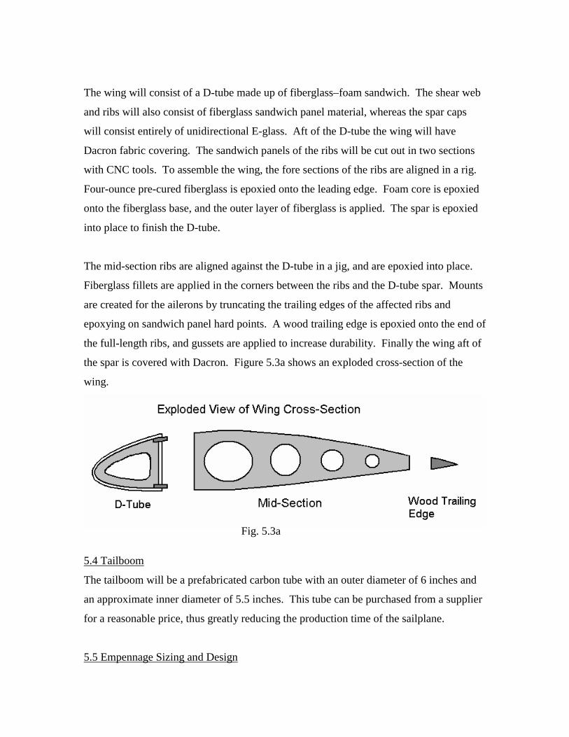
The wing will consist of a D-tube made up of fiberglass–foam sandwich. The shear web
and ribs will also consist of fiberglass sandwich panel material, whereas the spar caps
will consist entirely of unidirectional E-glass. Aft of the D-tube the wing will have
Dacron fabric covering. The sandwich panels of the ribs will be cut out in two sections
with CNC tools. To assemble the wing, the fore sections of the ribs are aligned in a rig.
Four-ounce pre-cured fiberglass is epoxied onto the leading edge. Foam core is epoxied
onto the fiberglass base, and the outer layer of fiberglass is applied. The spar is epoxied
into place to finish the D-tube.
The mid-section ribs are aligned against the D-tube in a jig, and are epoxied into place.
Fiberglass fillets are applied in the corners between the ribs and the D-tube spar. Mounts
are created for the ailerons by truncating the trailing edges of the affected ribs and
epoxying on sandwich panel hard points. A wood trailing edge is epoxied onto the end of
the full-length ribs, and gussets are applied to increase durability. Finally the wing aft of
the spar is covered with Dacron. Figure 5.3a shows an exploded cross-section of the
wing.
5.4 Tailboom
The tailboom will be a prefabricated carbon tube with an outer diameter of 6 inches and
an approximate inner diameter of 5.5 inches. This tube can be purchased from a supplier
for a reasonable price, thus greatly reducing the production time of the sailplane.
5.5 Empennage Sizing and Design
Fig. 5.3a

Through an iterative process, the sizing of the tailboom and horizontal and vertical tails
were found.
5.5.1 Horizontal Tail
For the horizontal tail, 0.35 < VH/VW < 0.55 is assumed. Vw was determined to be 2419
ft2. Values for the tail moment arm were assumed and then the area was calculated using
the horizontal tail volume equation. The chords and span can be determined from the
area using an assumed aspect ratio. Several of these initial values were tabulated until an
acceptable geometry was found. The final results are listed below.
AR = 5.5
S = 14.75 ft2
b = 9 ft
c = 1.64 (mean geometric chord)
λ = 0.7
lH = 17 ft (tail moment arm)
The tail moment arm is roughly the tailboom height.
5.5.2 Vertical Tail
The vertical tail size was found by assuming a vertical stabilizer volume comparable to
that of similarly configured sailplane designs. An area can then be determined through
the vertical stabilizer volume equation. With an assumed aspect ratio, the chords and
span can be determined.
AR = 1.5
S = 10.165 ft2
b = 3.90 ft
c = 2.60 (mean geometric chord)
λ = 0.7
lv = 17 ft (tail moment arm)
5.5.3 Attachment

The simplicity of design has been taken into account in the design of the vertical and
horizontal tail. The flat plate construction for both the vertical and horizontal tail was
selected to simplify and shorten construction time. Two pins along the tailboom and
fiberglass applied from the side of the surface to the tailboom will attach the vertical tail.
The rudder is constructed of the same flat plat design. The horizontal tail is constructed
to be removable for ease of transportation. Further, an aluminum tube is set through the
tailboom. The horizontal tail will then be placed over the exposed aluminum tube and
pinned with vertically oriented pins.
5.6 Cockpit Ergonomics
5.6.1 Instrumentation The instrumentation for this aircraft will consist of a compass, an airspeed indicator, a
variometer, a yaw string, and an altimeter. These instruments are the minimum
requirements the FDR has solicited for experimental aircraft. In addition, all other
accessories have been removed from the cockpit design in order to fulfill the project’s
main objective, which is to reduce costs and labor as much as possible.
The instrument panel will consist of a detachable aluminum plate with the altimeter,
airspeed indicator and variometer in the middle of the panel and the compass on top of
the dashboard. Furthermore, the yaw string will be taped to the sailplane’s canopy. The
altimeter will measure the aircraft’s altitude, and the variometer will be used for soaring.
In addition, the airspeed indicator will display the sailplane’s speed, which will not
exceed 60MPH, and the yaw string will be used for coordination.

Instrument Size Range Style Part-No Price Store
Airspeed
Indicator 3-1/8 in
0-75
MPH Pitot 10-02945 $223.00 http://www.aircraftspruce.com
Color
Marking kit ------- --------- ------- --------- $4.95 http://www.wingsandwheel.com
Altimeter
3 pointer
in Hg
scale
20,000
ft ------- ------------ $345.00
http://www.wingsandwheel.com
Compass ---------- --------- Airpath
model
C2300
Panel
mount
compass
$99.00 http://www.wingsandwheel.com
Variometer ------------ --------- ---------- ------------ $350.00 http://www.wingsandwheel.com
Fig.5.6.1A: Instrument description. It should be noted that for safety concerns the airspeed
indicator has a range of 10-20% higher than the never exceed speed. Furthermore, a mechanical
variometer will be used to avoid installing an electrical system.

Fig.5.6.1B Instrument Orientation

Fig.5.6.1C: The color marking kit will be used to satisfy the FDR regulations for airspeed
indicator by highlighting the different tolerable ranges in airspeed for the aircraft.
5.7 Control Mechanisms
The pilot seat will be upright, fixed, and nonadjustable since different sized seat cushions
will be used to compensate for the pilot’s size and shape. Temper foam will also be used
on the seat to cushion for crash safety ness. Furthermore, the controls for the cockpit will
be kept conventional since it is will be easier to install them than an adjustable seat
mechanism. The controls will consist of the following:
• Adjustable rubber pedals (will buy)
• Center stick (aluminum)
• Spoiler handle on left
• Release knob at base of panel (yellow or red)
• Hinge canopy on right side

5.7.1 Ailerons
The ailerons will be controlled with a pull-pull system running from the yoke to the wing
trailing edge. A bell crank will translate the pull-pull input to a push-pull rod connected
to the aileron.
5.7.2 Elevator and Rudder
Controls for the elevator and rudder will be pull-pull cables connected to the yoke and
rudder cables respectively.
5.7.3 Spoilers
The spoiler blades will be flat pieces of aluminum. Since our airfoil is fairly insensitive, it
should be acceptable that the spoilers don’t follow the airfoil contour. They will sit in a
fiberglass spoiler pan such that they are flush with the upper wing surface. The spoiler
pan will keep debris out of the wings as well as provide sealing to minimize interference
drag. Spoiler plates will be hinged to the trailing edge of the D-tube with piano hinge.
Spoilers will be held in their closed position by springs. They will be deployed by a cable
which pulls on a control horn. Cables were selected instead of pushrods because they are
lighter, cheaper, and easier to route. The cables will disconnect at the wing root to allow
for removal of the wings.


6.0 Stability and Control The stability of a glider is dependent upon the location of its center of gravity and neutral
point. In order to be stable, the center of gravity must lie in front of the neutral point. A
range of acceptable CG locations was found. In order to do this, the neutral point
location must be known. This was calculated using the neutral point equation located on
page 479 of Aerodynamics, Aeronautics, and Flight Mechanics. This point was
determined to lie 1.97 ft aft of the leading edge at the root. The CG typically lies
between 5-10% of the mean aerodynamic chord in front of the neutral point. This yields
a CG range of 1.74 ft to 1.85 ft behind the leading edge.

7.0 Drag Build-Up A spreadsheet format was used to help outline an approximation for the total drag. The
sailplane was broken into four main parts: fuselage, wing, horizontal tail, and vertical
tail. The drag was calculated individually and then combined to approximate the total
drag.
7.1 Parameters
There are several parameters used throughout the drag build-up. Their values are listed
as follows:
•Weight = 460 lbs
•Sea-level conditions are assumed:
Density (ρ) = 0.002377 slugs/ft3
Kinematic Viscosity (υ)= 0.000157 ft2/s
7.2 Wing
An approximation for our span-wise efficiency factor was used to help compile further
data: e = 0.94 (linear tapered wing planform). Also, the SM701 airfoil data was used in
calculations.
7.2.1 Calculations
In starting, two columns were created for velocity in knots and feet per second; the data
began at 25 knots and ended at 60 knots. Next a CL was calculated for each velocity:
CL = 2W ρV2S
Then the induced drag coefficient was found using:
CDi = CL2
πeAR Where the aspect ratio and is defined as:
AR = b2
S Then the Reynold’s Number was calculated at each velocity:
Re# = Vc υ

Next, the CD for each velocity was found from the CL vs. CD graph of the SM701. The
calculated CL was used to locate the corresponding CD on the graph.
The drag of the wing was found by totaling the drag at each velocity; which is found
using:
D = 0.5ρV2S(CDi + CD)
7.3 Horizontal Tail
The drag for the horizontal tail is calculated similarly to that of the wing. Though for the
horizontal tail CL is assumed to be a constant 0.15 for all velocities. This is due to the
airfoil characteristics. Because CDi varies only with CL, CDi is also constant for the
horizontal tail. Though the CD changes since Reynolds’s Numbers will vary for different
velocities.
7.4 Vertical Tail
Again, the drag is calculated similarly to that of the wing. But, CL is assumed to be zero
because the vertical tail is not a lift-contributing factor on the glider. Thus CDi will also
be zero. The profile drag is the only contributing drag component for the vertical tail.
7.5 Fuselage
This portion of the drag build-up is by a far the most complicated method. Because of
the fuselage’s geometry, it must be broken up into sections to adequately approximate its
total drag.
For simplicity, transition from laminar to turbulent flow was assumed at the canopy;
approximately 2 ft from the nose of the glider.
To begin, the glider was broken into 1 ft sections. At each point the circumference was
determined for use in later calculations.

x (ft) h (ft) X (ft) h (ft) x (ft) h (ft) x (ft) h (ft) x (ft) h (ft)
0 0 6 11.7 12 8.42 18 3.67 24 3.67
1 3 7 11.9 13 6.49 19 3.67 25 3.67
2 4.17 8 11.7 14 4.42 20 3.67 26 3.67
3 8.81 9 11.6 15 3.67 21 3.67 27 3.67
4 10.1 10 11.2 16 3.67 22 3.67 28 3.67
5 11.1 11 10.5 17 3.67 23 3.67
At each length and velocity, Reynold’s Numbers were calculated for each velocity. These
velocities were also used to calculate skin friction, Cf, and drag was calculated using Cf
for CD. For laminar flow skin friction is found using:
Cf = 0.664 (Re)1/2
and for turbulent flow:
Cf = 0.0576 (Re)0.2
Drag is then found using:
D = 0.5Cf ρU2S
for both laminar and turbulent flow. The drag for each velocity is then summed up for
both the laminar and turbulent flow cases to achieve the total drag for the fuselage. (It is
may be useful to note that these are Blasius Solutions – flat plate solutions; flat plates
were used for the empennage and fuselage.)
7.6 Total Drag
The drag was calculated for each of the above four sections individually and then
combined for a total drag. To compensate for inference drag the total drag is multiplied
by 10% and added to itself to generate a new total drag:
NewDtotal = (Dtotal)10% + Dtotal
Trim drag has been neglected in these calculations due to its effects not being large
enough to be worth consideration under the given flying conditions.

7.7 L/D
The lift to drag ratio for each velocity can be calculated for the total drag. Notably, the
assumption that L = W must be made to do so (weight does not vary).
L = W D Dtotal
7.8 Drag vs. Velocity
The drag polar, drag plotted vs. velocity, shows the quadratic relationship between lift
and drag (as can be seen from the graph).
Vmin ~ 42.2 ft/s
Drag Polar
0
5
10
15
20
25
0 10 20 30 40 50 60 70
V elocit y ( knot s)
7.9 Velocity vs. Vsink
V vs. Vsink
-18
-16
-14
-12
-10
-8
-6
-4
-2
00 10 20 30 40 50 60 70
V (knots)
Vsin
k (ft
/s)

7.10 L/D vs. Velocity
L/D vs. Velocity
0
5
10
15
20
25
30
0 10 20 30 40 50 60 70
V elocit y ( knot s)

8.0 Loads
8.1 V-n Diagram
The load diagrams were calculated using standard JAR-22 procedures. The following
values were assumed in order to calculate critical points on the diagram:
Cd min = .03
Vs1 = 25 kts (Stall speed)
These yield the following values:
VA ≈ 58 kts (Design maneuvering speed)
VD ≈ 80 kts (Design maximum speed)
8.1.1 Maneuvering
V-n Diagram
-4-3-2-10123456
0 20 40 60 80 100
V (knots)
n
8.1.2 Gust
For the gust load case, the load curve is found by plotting the equation in part (a) of JAR
22.341 using gust cases of ±7.5 m/s and ±15 m/s. The following values were used to
solve the equation:
ρ = 1.190 kg/m3 (density at 1000ft)

a = 5.6 (slope of wing lift curve)
k = .432 (gust alleviation factor)
µ = 5.12 (non-dimensional sailplane mass ratio)
This can be plotted along with a do not exceed loading from the JAR-22 to find the gust
envelope.
V-n diagram (Gust)
-4
-3
-2
-1
0
1
2
3
4
5
6
0 10 20 30 40 50 60 70 80 90
V (knots)
n
8.2 Flight Forces
8.2.1 Spanwise Lift
The lift distribution was approximated as proportional to the chord such that the total lift
was equal to the weight.
8.2.2 Spanwise Drag
The drag distribution was approximated as proportional to the chord such that the total
lift was equal to the weight.
8.2.3 Spanwise Shear

The strut takes most of the shear force due to lift, which can be seen in the shear graph.
Shear Force vs. x
-150.00
-100.00
-50.00
0.00
50.00
100.00
150.00
0 5 10 15 20 25
x from root (ft)
Shea
r for
ce (l
b)
8.2.3 Spanwise Moment
The maximum moment occurs at the strut, and causes the moment at the root rib to go to
zero.
Moment vs. Distance From Root
0100200300400500600700800900
0 5 10 15 20 25
x from root (ft)
Mom
ent (
ft-lb
)

9.0 Weight Estimate The following weights were found by comparing similar components on existing aircraft:
Fuselage ......................................................................................................................... 80lb
Vertical Tail .................................................................................................................. 10 lb
Horizontal Tail .............................................................................................................. 13 lb
Wing............................................................................................................................ 180 lb
Max Pilot Weight........................................................................................................ 177 lb
Total..........................................................................................460 lb
10.0 Cost Estimate The following prices for each component were found using internet search and
Instrumentation ............................................................................................................$1500
Covering.......................................................................................................................$1500
Hardware........................................................................................................................$650
Composites...................................................................................................................$2000
Tailboom........................................................................................................................$750
Misc..............................................................................................................................$2000
Total ...................................................................................................................... $8400

11.0 Time Projection
Ribs Spar Vertical Horizontal Tailboom Bulkheads Skin Controls1st layer 4 jig 2 wing skin 16core 16 align in jig 1 Htail 12
outer 8epoxy-glass fillets 9 Vtail 8
fuselage-tailboom 24fuselage-wing 24
Time (lab-hours) 28 12 16 12 12 20 2 16 30 60 84
Total Lab Hours Total Labs Total WeeksSemesters (ideal)
Semesters (ideal/realistic)
292 73 36.5 3.318181818 ~ 4 - 5
Time Estimate
AttachmentsD-Tube AlignmentWing FuselageTail

12.0 Conclusion Through innovative design and supporting calculations, the KS-1 has proven to be an
easy-build sailplane whose fabrication is well within the reach of the AERSP 204H/404H
students. The clever utilization of prefabricated parts in conjunction with a relatively
simple, modular design has established a sailplane design that, in the least, has paved the
way to a breath of knowledge. Further, the KS-1 may change the entire effectiveness of
the sailplane class. In the future, the class will have found that a sailplane can be built
within a reasonable time as opposed to wasting countless hours in a fabrication standstill.
Consequently, with the breakthrough design of the KS-1, the sailplane class can take new
shape and soar to new heights.


![Osprey - Aerospace - Tiger Squadrons [Osprey - Aerospace].pdf](https://static.fdocuments.in/doc/165x107/55cf9675550346d0338b9dbe/osprey-aerospace-tiger-squadrons-osprey-aerospacepdf.jpg)
