THE KNOOP MICROHARDNESS TESTER AS A ... KNOOP MICROHARDNESS TESTER AS A MINERALOGICAL TOOL1 Honecn...
13
THE KNOOP MICROHARDNESS TESTER AS A MINERALOGICAL TOOL1 Honecn WrNcnpr-r-2 Ansrn.ncr The Tukon testing machine with a Knoop indenter has useful possibilities in the meas- urement of hardness of mineral specimens. Not only does the instrument afiord numerical hardness values such as argentite:2S, calcite:lO0, fluorite:150, magnetite:700, corundum:2000, SiC:3000, and diamond:about 8000, but it repeats these numbers with an accuracy of between 2 and 5 per cent when applied to a given crystal face under constant conditions. Surprisingly large variations of hardness have been found in many crystals, the variation being a function of the orientation of the surface tested and of the orientation of the long axis of the Knoop indenter in that surface. The results of 479 tests in 92 difierent orientations on 16 difierent minerals and mineral-like substances indicate the instrument is worthy of further study as a mineralogical tool. INrnopucuoN Metallurgists have long used various types of indenters for testing the hardness (defined as resistance to deformation) of metals. Attempts to apply to minerals the Rockwell, Vickers, and other types of machines which measure hardness in terms of deformation of the specimen by penetration of a standard-shapedpoint applied by a specified machine, have met with little success because of the tendency of minerals to frac- ture during the penetration of the indenter. Since the fracture represents displacement and deformation of other material than that immediately adjacent to the point of the indenter, greater penetration takes place than is proper for the indenter and its associated machine. Moreover, the displacement due to fracture cannot be measuredreadily, and therefore introduces an unknown factor into the measurement.Experiments con- ducted at the Research Laboratories of the Hamilton Watch Company have suggested that of all the various machines for measuring hardness by indentation, the Knoop microhardness tester may be the only tool that can give valid, or at least consistent, readings of the hardness of minerals. Tun Kwoop InppNrrn Knoop, Peters, and Emerson (1939) described an unusually sensitive pyramidal-diamond indenter which is known as the microhardness tester, or Knoop indenter. The Wilson Mechanical Instrument Company manufactures a machine, the Tukon tester (Fig. 1), which utilizes this indenter. In measuring the hardness of a specimen, a polished flat sur- r Contribution from the Research Engineering Division, Hamilton Watch Company, Lancaster, Pennsylvania. 2 Research crystallographer, Hamilton Watch Company, Lancaster, Pennsylvania.
Transcript of THE KNOOP MICROHARDNESS TESTER AS A ... KNOOP MICROHARDNESS TESTER AS A MINERALOGICAL TOOL1 Honecn...
THE KNOOP MICROHARDNESS TESTER ASA MINERALOGICAL TOOL1
Honecn WrNcnpr-r-2
Ansrn.ncr
The Tukon testing machine with a Knoop indenter has useful possibilities in the meas-urement of hardness of mineral specimens. Not only does the instrument afiord numericalhardness values such as argentite:2S, calcite:lO0, fluorite:150, magnetite:700,corundum:2000, SiC:3000, and diamond:about 8000, but it repeats these numberswith an accuracy of between 2 and 5 per cent when applied to a given crystal face underconstant conditions. Surprisingly large variations of hardness have been found in manycrystals, the variation being a function of the orientation of the surface tested and of theorientation of the long axis of the Knoop indenter in that surface. The results of 479 testsin 92 difierent orientations on 16 difierent minerals and mineral-like substances indicate theinstrument is worthy of further study as a mineralogical tool.
INrnopucuoN
Metallurgists have long used various types of indenters for testing thehardness (defined as resistance to deformation) of metals. Attempts toapply to minerals the Rockwell, Vickers, and other types of machineswhich measure hardness in terms of deformation of the specimen bypenetration of a standard-shaped point applied by a specified machine,have met with little success because of the tendency of minerals to frac-ture during the penetration of the indenter. Since the fracture representsdisplacement and deformation of other material than that immediatelyadjacent to the point of the indenter, greater penetration takes placethan is proper for the indenter and its associated machine. Moreover, thedisplacement due to fracture cannot be measured readily, and thereforeintroduces an unknown factor into the measurement. Experiments con-ducted at the Research Laboratories of the Hamilton Watch Companyhave suggested that of all the various machines for measuring hardnessby indentation, the Knoop microhardness tester may be the only toolthat can give valid, or at least consistent, readings of the hardness ofminerals.
Tun Kwoop InppNrrn
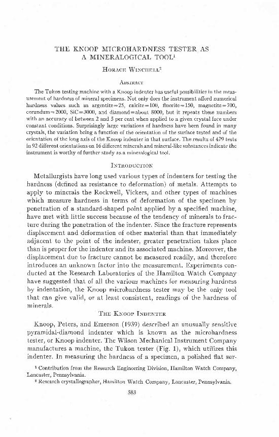
Knoop, Peters, and Emerson (1939) described an unusually sensitivepyramidal-diamond indenter which is known as the microhardnesstester, or Knoop indenter. The Wilson Mechanical Instrument Companymanufactures a machine, the Tukon tester (Fig. 1), which utilizes thisindenter. In measuring the hardness of a specimen, a polished flat sur-
r Contribution from the Research Engineering Division, Hamilton Watch Company,Lancaster, Pennsylvania.
2 Research crystallographer, Hamilton Watch Company, Lancaster, Pennsylvania.
584 HORACE WINCHELL
face is first prepared. The Knoop indenter is then brought into contactwith this surface for 20 seconds (the minimum time found adequate to as-sure consistent results), with a known load. The indentation thus pro-duced is measured with a microscope, and the hardness number 1 is pro-portional to the load divided by the area of the indentation. For rela-tively heavy loads-say 1 to 3 kilograms-the hardness number is essen-tially independent of the load. Tate (1944) showed, however, that this isnot strictly true for loads of 100 grams or lesslhe concluded that the ap-
r.:.;i1it1l,ra,;;':l
Frc. 1. Tukon testing machine, showing Knoop indenter and rising platformon which specimens are teSted.
plied load should always be reported with the hardness number: thatpractice is followed here. The Tukon tester is provided with severalweights corresponding to loads from 100 grams up. Our instrument is notprovided with smaller loads, but slight changes could easily be madewhich would accomplish the purpose if necessary.
The latest model of the Tukon testing machine embodies an electro-
THE KNOOP MICROHARDITESS TESTE,R
magnetic device for applying the load without overloading by impactbetween the specimen and the diamond indenter. The Hamilton instru-ment was rebuilt to afford that protection against shock after about halfof the corundum tests reported here had been completed. The error dueto impact before installation of the device is believed to be mostly the re-sult of fractures in brittle specimens, although there must have been somedecrease of the hardness number due to impact of the unguarded indenterin the old form of the instrument. The tests of a fluorite specimen (Table2) before and after rebuilding show essentially no change in hardnessnumber due to this modification to the instrument.
vvmvnS E C T I O N A A
I N D E N T A T I O N
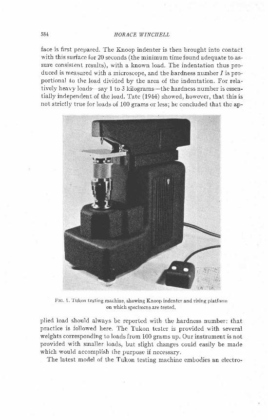
Frc. 2. Knoop indenter, showing angles betv'een the edges of the flat pyramidal diamondpoint. Approximate ratios are: length:width: 7.1 : 1, and length: depth:30: 1.
The K.noop indenter possesses certain advantages over other similarhardness measuring tools, and these are exactly the advantages thatmake it suitable for testing minerals. Figure 2 shows the shape of theindenter. An extremely shallow penetration is sufficient to produce anindentation long enough to be measured with a relative accuracy of aboutt/o. Thw, for an indentation 100 microns (0.1 mm.) long, the penetra-tion is only about 3 microns. The smallness of the penetrtaion was dem-onstrated by Peters and Knoop (1940) when they showed that a validreading of the hardness of electrolytic chromium plate can be obtained,regardless of the nature of the base metal upon which the chromium wasdeposited, if the thickness of the plating is greater than 0.001 inch or25 microns. Thevalidity of extending this conclusion to cover small grainsin a polished section of a mineral assemblage is not debated here, but doesnot seem unreasonable for roughly equant grains which appear about 100microns in diameter in the plane of the section, especially if several suchgrains are tested and found to give consistent results. By reducing theIoad applied to the indenter, the length of the indentation can always bekept small.
J6J
|.
I N D E N T E R
,.::_::lf
HORACE WINCHELL
Car,curertoNs
The conversion of the measured length of the indentation and the loadon the indenter to the hardness number is made by means of the follow-ing formula, which may be expressed by a family of parallel straight lineson logarithmic graph paper:
I :W / L2c1:Knoop hardness number.
W:Load applied to the indenter, in kilograms.Z:Length of the indentation, originally defined as in centimetersl but Z may be
measured in any length units desired and the conversion factor to centimeters maybe included in c.
t:a constant depending upon the shape of the indenter. It may also include conver-sion factors depending upon the units actually used to measureW and L.
As stated above, the equation may be expressed by straight lines, onefor each applicable load, on logarithmic graph paper. The scale of thegraph may be made such that there will be no danger of introducing er-rors that are larger than probable errors inherent in the measurementof the indentation by optical methods.
The form of the above equation shows that to achieve a given relativeor percentage accuracy in I, L must be measured with a maximum rela-tive or percentage error one-half as great. For example, if Z is measuredwith an error of 1 part in 100, the resulting error in 1 would be 2 parts in100.
Rnrrasrrrrv
To evaluate the accuracy or consistency of the Tukon tester in thelaboratories of the Hamilton Watch Company, for mineral testing pur-poses, several specimens were tested many times each. The results willbe found summarized and expressed as probable error3 in Table 2. It wasfound that most hardness readings will be repeated within about 2 to 5per cent of the average, when many indentations are made in the sameorientation on the same crystal surface. The probable error of an obser-vation or of the average of several observations is appreciably increasedif anyof the observations are made on indentations associatedwith cracksor other fractures. In accordance with logical arguments that the highestreading will be obtained with the least fracturing, it was concluded thatthe ma*imum of a series of readings should be selected if fractures appearwith any of them; but the al)erage should be considered the best value ifno fractures occurred. According to that convention, the best value isindicated in Table 2 in boldface.
3 If a observations of a quantity are represented by ry x2, . . ., rut and their mean by f,and their respective deviations from f by d;, then the probable error of any individual ob-servation is 0.6745 \/rd?/ (tt- D and the probable error of the mean is 0.6745 1/tE/
"G4.
THE KNOOP MICROHARDNASS TESTER 587
A note of caution must be included here regarding these measures of
accuracy. The "probable error" shown in Table 2 and defined above is
really a measure of the self-consistency of the given set of observations. ft
takes no account of possible systematic errors such as the dependence of
the hardness number upon the load on the indenter (Tate, 1944), or im-
perfectly shaped or polished indenters. "Probable errors" also do not in-
clude errors due to faulty specimen preparation (polishing, Ievelling, etc.)
or improper adjustment of the Tukon testing machine. Our efforts were
mainly to control such variables by holding them constant. We havemade no attempt to determine the importance of such factors for this
study. Another still undetermined source of possible error is the crystal-
lographic orientation of the diamond indenter. So far as is known, themakers of the indenters do not attempt to hold this constant. This fac-
tor would undoubtedly be negligible for soft and medium specimens but
in testing materials of great hardness, the elastic properties and hardness
of the diamond itself would be of the same order of magnitude as those
of the specimen, and should therefore be considered. It is our impressionthat such properties would vary appreciably with the orientation of thediamond.
For all these reasons, then, the reader is cautioned not to accept un-critically the fourth, nor even the third significant figures of the hard-ness numbers quoted in Table 2. The probable error alone (2/6 to 5/s)would generally indicate that the fourth digit can have little significance.Nevertheless, until fuII information on validity of results is available from
all sources. it seems best not to round ofi the numbers farther than to thenearest 5 units in the fourth significant figure. This consideration prob-
ably would not affect results for soft materials, but might noticeablyaffect those reported for materials of greater hardness than 1000.
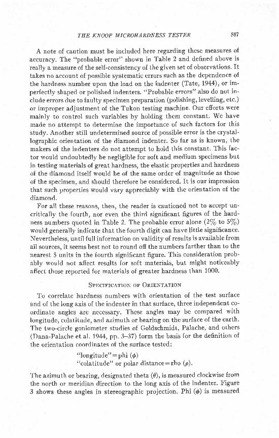
Spncntcarror.r ol OuBNrartoN
To correlate hardness numbers with orientation of the test surface
and of the long axis of the indenter in that surface, three independent co-
ordinate angles are necessary. These angles may be compared with
longitude, colatitude, and azimuth or bearing on the surface of the earth.
The two-circle goniometer studies of Goldschr'nidt, Palache, and others(Dana-Palache et al. 1944, pp.3-37) form the basis for the definition of
the orientation coordinates of the surface tested:o'longitude":phi (0)
"colatitude" or polar distance:rho (p).
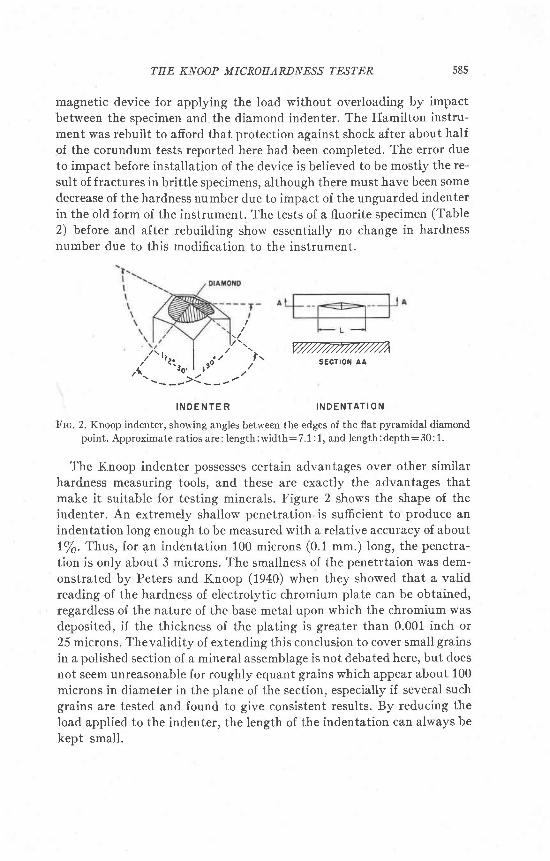
The azimuth or bearing, designated theta (g), is measured clockwise from
the north or meridian direction to the long axis of the indenter. Figure
3 shows these angles in stereographic projection. Phi ({) is measured
588 HORACE WINCHELL
PRISM ORb - PrNAcoro
(oro) oR (tizo)
Frc. 3. Stereographic projection illustrating the definitions oI g, p,0, the angular co_ordinates of the test surface and of the long axis of the indentation therein, taken with re-spect to conventional crystal axes of any system. For the orientation p:}o,6 is inde-terminate and d is speciauy defined as the direction-angle, measured around the funda-mental circle normally used for 4.
clockwise about the fundamental circle of the projection from the pointrepresenting the plane (010) or (1120). Rho (p) is the polar angle, meas-ured radially outward from the center of the projection (the point repre-senting the axis of the prism zone). And theta (d) is measured clockwiseabout the point representing the test plane. These defi.nitions serve forall points except the pole of the sphere (p:0"). At this point, 0 mustbe defined specially, as the direction-angle measured like { around thefundamental circle.
It will be evident that these definitions permit choosing the followingranges for the three coordinate angles:
- 180'<., < 180'0'< p S 180'0"<, <360"
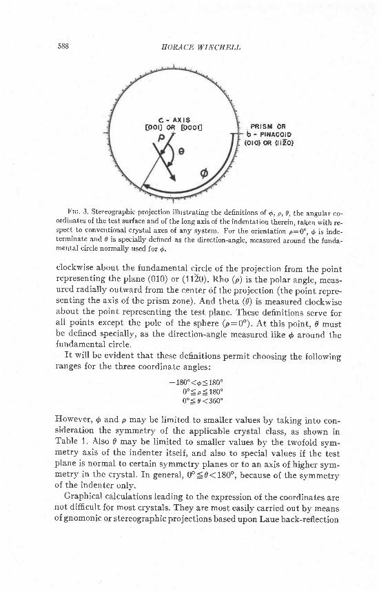
However, d qnd p may be limited to smaller values by taking into con-sideration the symmetry of the applicable crystal class, as shown inTable 1. Also 0 may be limited to smaller values by tbe twofold sym-metry axis of the indenter itself, and also to special values if the testplane is normal to certain symmetry planes or to an axis of higher sym-metry in the crystal. In general,0o(0(180o, because of the symmetryof the indenter only.
Graphical calculations leading to the expression of the coordinates arenot diffi.cult for most crystals. They are most easily carried out by meansof gnomonic or stereographic projections based upon Laue back-reflection
c - A x l s[oor] oR [ooo0
THE KNOOP MICROHARDNESS ?ESTER 589
TesLE 1, Lrurrs ol VanretroN or d AND p R-nsur,trNc lnou Cnvster- Svul,rnrnv
SyrnmetryClass I t I tl
S y m b o l l N a m e t t r l
4/m47
2/m2
4/^4,4
4/m44
2/^)
mm
3J
J
6o
3
2/^2
m
NormalPlagiohedralTetrahedralPyritohedralTetartohedral
NormalTrapezohedralHemimorphicTrigonalTripyramidalPyramidal-HemimorphicTrigooal-Tetartohedral
RhombohedralTrapezohedralRhombohedral-HemimorphicTri-RhombohedralTrigonal-Tetartohedral-Hemimorphic
NormalTrapezohedral
HemimorphicSphenoidalTripyramidalTetartohedralPyramidal-Hemimorphic
0000
-90
000
-3000
-60-30
0-30-60-60
306030306060603060306060
55
55
00000
4590459090
9090
1809090
180909090
18090
180
2/m2
m2
2/m2
mm
2/^2
m
6/m666
6/m6o
3J
.)
9090
180909090
180
0000000
45454545909090
2/m2
m2
000000000000
0-45
0-45
0-90
0
fsometric Svstem
Hexagonal System
Tetragonal System
Orthorhombic System
2/m22
9090
180
909090
9090
180
NormaISphenoidalHemimorphic
0-90
0
NormalHemimorphic
Clinohedral
Monoclinic System
9018090
000
Triclinic System
NormalAsymmetric
180180
90180
590
Substance Tested(Tests conducted on polishedartificial surfaces unless other-wise noted.)
Beta Alunina,
crystal surface
Argentite
Calci te,
cleavage surface
same surlace
same surface
Corundum, syntbetic
Colorless block
same sutface
same surlace
same surface
Colorless block
same sutface
same surface
same surface
Colorless block
same surface
same surface (3)
selected indentations (,1)
selected indentations (S)
Light ruby block
same surface
same surface
same surface
Light ruby block
same surface
same sulface
same sutface
Light ruby block
same surface
Light ruby slab
same sutface
same surface
same surface
Light ruby slab
same surface
same surface
same surface
Light ruby slab
same surface
same surface
same sudace
Light ruby slab (6)
same surface
same surface
same surface
same surface
Ligbt ruby rod
same surface
8
t 4
- l
-20
14
- t 9
HORACE WINCHELL
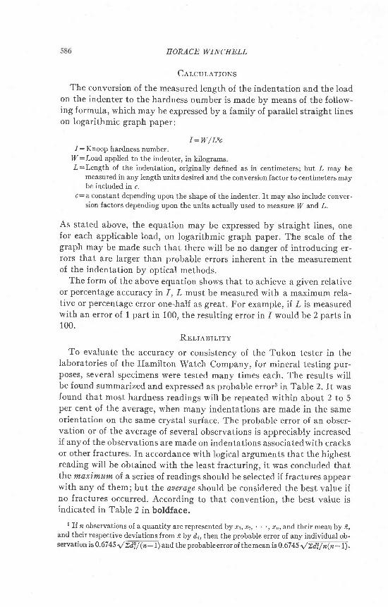
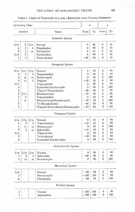
Tl,r;,n 2. KNoor HenoNEss AS A Fur.rcrroN ol ORTENTATToN rN CERTATN Mrrrner,s
Orientation Hardness
AngularCoordinates
( 1 ) . 9 -
9 =
z
3
5
5
102524
109026
1 1 8E5
o l r o t - l3S | 1011eo I loir
var I 0001
t30 | lo lo0 11t0
36 11t0e2 ) 11ro
r44 | 1r2o26 | 0001
r r2 00013s I 000r80 I 0001
128 0001r71 I 0001
var 18var I 13
.1 1960 | 22101 1 1 8 6 5 1 2 1 0 0
r012011 I7270
o I loro . 1 1 2 0 6 5 1 2 1 3 s47 | ror-o . r l 2 1 3 5 l 2 2 t O90 | 1010 .1 | 2100 2t75
r3o I lolo .1 | 1900 I 196047 I 1t2o r 206s I 2135eo | ilto .1 1995 | 2065
133 | 1120 . t 1 2 1 7 5 1 2 3 3 5r7e J lrro 1 | 1900 2030
0 | 0001 .1 1960 I 199530 | 0001 1o1o I 3 . r l 1 7 2 s l 1 9 3 0
var 0001 var I J I 1 I 1865 22tOvar | 0001
0001
121,O
1 100
00011120
1270
0001
I 100
1010t2to
1100
o I 1o1o 0001 | 347 | r0I090 I 1o1o
.1 2065 2135t ) 2 t 3 5 1 2 2 1 0
. t I t 7 5 0 1 9 0 0
. r 1 1 9 6 0 1 2 1 0 0| | 2250 24201 206s | 2250
.1 | 19oO 2065
. 1 1 1 6 7 0 1 1 9 0 0
. l | 18J5 I 2065I t810 | 1960
.3 I 1s l0 1630
.3 | 135s 15353 1365 15353 t26s I t425
. 3 1 1 6 4 5 1 1 7 2 0
. 3 t 1 5 2 5 ) 1 7 2 0
.3 181s | 18703 1 1 7 6 s 1 1 8 0 0
. J t 1 6 4 s l l 8 r 5
. 3 1 1 6 0 0 i 1 7 0 5
. 3 1 1 7 6 5 1 1 8 s 0, 3 t 1 7 8 5 1 1 8 5 0. 3 1 1 1 6 0 / 1 9 0 5. 3 1 1 6 1 5 1 1 7 8 53 1 1 7 6 s i 1 9 0 53 1470 | 1765
. 3 1 1 1 6 0 l U 2 0
.1 | 1780 l& !5
3355
7t204283
1331794388
142l / J
var
24095
12963
154
58 128a a
o
4
. l l 2 t o o l 2 2 l o 2t45
uF
105525
1 1 699
2110 | 162185 | r72135 25 | xt940 L42 l 0 o l 2 5 l x2O3O | 23 x2240 | 231965 ,14
1985 | 13 x1 8 5 0 1 7 5 1 x2 0 5 0 1 4 9 1 x20u5 | rr2OlS 53 I x2085 I 162175 | rs2040 | 2a23lO 362175 | 39t985 321765 | 76 x1840 301935 I 45lgm | 3r
26
1560 I x1435 | x1 4 2 0 1 l x1 3 5 0 1 l x1690 | x1640 | xl8s0 I ir78s I I1770 | x1650 i x1800l&!01 7 2 5 l 7 9 l x1705 I 51850 | 28 x1 6 6 0 l 7 f l x1 5 7 0 l l l 5 ]1 8 1 5 1 / x
Substance Tested(Tests conducted on polishedartificial surfaces unless other-wise noted.)
Light ruby rodsame surface
Light ruby rodsame surlace
Dark ruby slabsame surfacesame surlacesame surface
Fluoriterepeat run (10)same surfacerepeat run (10)
Galena (7)same surface
Galena (7)same surface
GlassMicro slideCover glassHigh-alumina glass lor jewel
bearingsFire polishedMechanically polished
Gypsum,cleavage surfacesame surfacesame surface
Kyanitesame surface
Kyanitesame surface
Kyanitesame surface
MagnetiteMagnetite
Quartz, crystal facesame sorlacesame sulface
Quartz, crystal facesame surfacesame surface
Quartz, crystal facesame surfacesame surface
Silicon carbide (9)Black, crystal lace (9)
same surlacesame surface
same surface, average
45
28
-24
0
42
-30
30
70
104530
TEE KNOOP MICROHARDITESS TES?ER
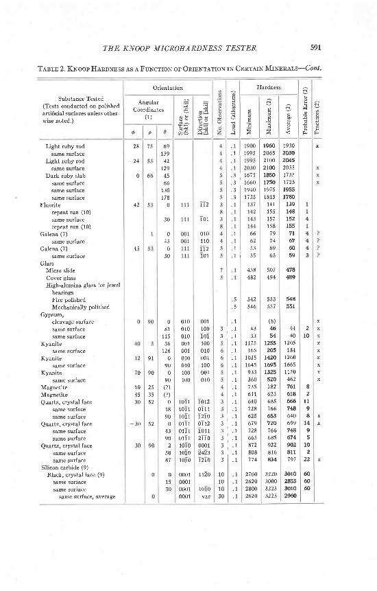
Tesm 2. Kwoop Heaarrss AS A FuNcrroN oF ORTENTATToN rN CERTATN MrNrnars-Cazl.
Orientation Hardness
591
AngularCoordinates
( 1 )
x
!
001100101100010001100001010
ti
P
Fr
6915942
129
861301 7 8
0
30
0450
30
r96020652r0021001850r750t97 51815
14115515715879
6965
507494
553557
(8)M54
I255205
142016951325520182623685766653720
6859228 1 6434
3220300032253225
19302030204520551 7 5 517251955r780
139l4181521557 l676059
4784ES
5485JI
4440
1205184
126016651t2046276r6186667864069978674m2811797
30ro285530102960
1 | 1995
3 1675. 3 1 6 6 0.s I ts+o
112
1 0 1
0 1 01 1 0
ll21 0 r
70120 l 1112toor12101 12lro00012423t2LO
ll20
1010var
3 . 1. l. 1. 1I
. l
. 1
. 1
. 1
. 1I
3 l3 | . 13 | . 13 I . 13 13 L . 13 | . 1
3 I 1735
1 6 6
1 5 3. l i J J
438482
5. 5
542546
4333
1 1 7 516s
103516459333607356 1 164072862867972866s872808
2760262028002620
. 108 1
1 1 536
t260
900
90(?)(? )
o48900
4390
25087
9 1
q0
253552
52
90
0
010010010001001010010100100
10r 1101 1101 1011 10 1 1 1011 1101010101010
0001000100010001
2l0
82
l l98
t49
102
22
xx
xxxx\
10101 030
0l 5
30
606060
592 HORACE WINCHELL
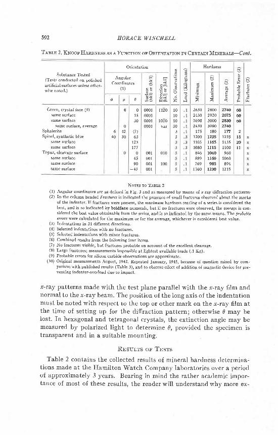
T,tsrr 2. KNoopHeroNrss es a FuNcr:rolq or.OnrcNrarroN rN Cnnrarx MrNmars-Cozl.
Orientation Hardness
2800292030003000
1801235l165l l 1 51040l l@985
t230
Substance Tested(Tests conducted on polishedartificial surfaces mless other-rvise noted.)
Green, crystal face (9)
same surface
same surface
same surface, averageSphalerite
Spinel, s5mthetic blue
same surlace
same sutface
Topaz, cleavage surf ace
same surface
same surface
same surface
AngularCoordinates
( 1 )c -
a =
F
'-l
e
zo
640
0
04230
0
0l . )
30
000t000100010001
r120
1010var
2650213026902430
17512001 1051080846889169
1160
274jJ26752430274JJ
17712251 1351 100960
1060894
t21S
60@60
2l 520l l
10101030
33
(?)63
123177
04590
-45
001001001001
NOTES To TABLE 2(1) Angular coordinates are as defined in Fig. 3 and as measured by means oI r-ray diffraction patteus'(2) In the column headed Fractures is indicated the presence of small fractures observed about the marks
of the indenter II fractures were preseot, Lhe na$nrm hardness reading of a series is considered thebest, and is so indicated by botdface numerals, but if no fractures were obseryed, the awrage is con-sidered the best value obtainable lrom the series, and is so indicated by the same means The probableerrors were calculated for the maximum or for tbe average, whichever is considered best value.
(3) Indentations in 31 difierent directions.(4) Selected indentations with no fractures.(5) Selected indentations with minor Jractures.(6) Combined results from the following Iour items.(7) No fractures visible, but fractures probable on account of the excellent cleavage.(8) Large fractures; measurements inpossible at lightest available loads ( 1 Kg).(9) Probable errors lot silicon carbide observations are approximate
(10) Original measurements August, 1942. Repeated fanuary, 1945, because of question raised by com-parison with published results (Table 3), and to observe efiect of addition oI magnetic device for pre-venl-ing indenter-overload due to impact.
tc-ray patterns made with the test plane parallel with the tr-ray film andnormal to the r-ray beam. The position of the Iong axis of the indentationmust be noted with respect to the top or other mark on the r-ray film atthe time of setting up for the diffraction pattern; otherwise d may beIost. In hexagonal and tetragonal crystals, the extinction angle may bemeasured by polarized light to determine 8, provided the specimen istransparent and in a suitable mounting.
RBsurrs oF TESTS
Table 2 contains the collected results of mineral hardness determina-tions made at the Hamilton Watch Company laboratories over a periodof approximately 3 years. Bearing in mind the rather academic impor-tance of most of these results, the reader will understand why more ex-
THE KNOOP MICROHARDTESS TEST.E.R
tensivg tests cannot easily be made here. This list does include a wide
enough variety of minerals and mineral-like materials to indicate very
promising possibilities for application of tbe K-noop indenter to deter-
minative mineralogy and to crystallography. Several type-minerals in
Mohs' scale, and some in the scale of hardness of Talmage (1925), are
included in Table 2. It should be emphasized that determinations from
fractured indentations marked "x" were of a reduced order of accuracy
because of the fractures. Such determinations should not be considered
final nor necessarily even approximately accurate; they are the best we
have available, however, and it will be noted that even in spite of the
uncertainty introduced by the presence of fractures, the fractures them-
selves appear to have been fairly consistent for any given orientation, and
the readings therefore were fairly constant. Analysis of the table will
show that the largest probable error for a good determination is less
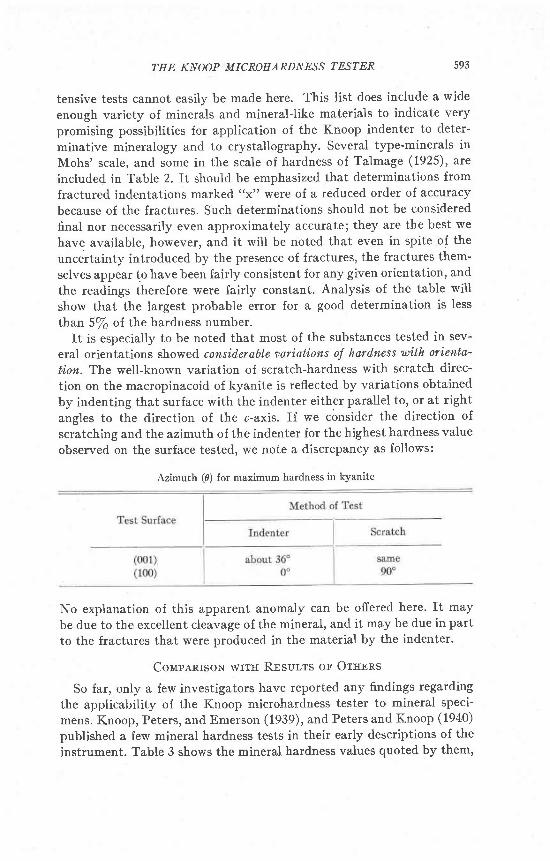
than 5/6 of the hardness number.It is especially to be noted that most of the substances tested in sev-
eral orientations showed considerable varintions oJ hard,ness with or'iento-
ticn. The well-known variation of scratch-hardness with scratch direc-
tion on the macropinacoid of kyanite is reflected by variations obtained
by indenting that surface with the indenter either parallel to, or at right
angles to the direction of the c-axis. If we c6nsider the direction of
scratching and the azimuth of the indenter for the highest hardness value
observed on the surface tested, we note a discrepancy as follows:
Azimuth (0) {or maximum hardness in kyanite
593
No explanation of this apparent anomaly can be offered here' It may
be due to the excellent cleavage of the mineral, and it may be due in part
to the fractures that were produced in the material by the indenter.
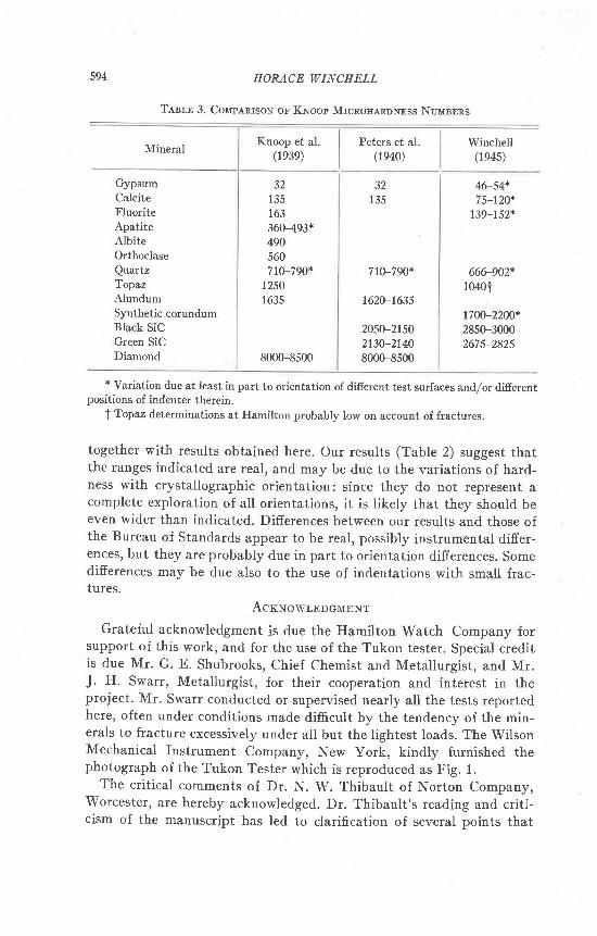
Colrpanrsorq wrrrr RESULTS ol OTHERS
So far, only a few investigators have reported any findings regarding
the applicability of the K.noop microhardness tester to mineral speci-
mens. Knoop, Peters, and Emerson (1939), and Peters and K.noop (1940)
published a few mineral hardness tests in their early descriptions of the
instrument. Table 3 shows the mineral hardness values quoted by them,
594 HORACE WINCHELL
Knoop et al.(1e3e)Mineral
Peters et al.(1e40)
Winchell(1e4s)
GypsumCalciteFluoriteApatiteAlbite
Orthoclase
QuartzTopazAlundumSynthetic corundumBlack SiCGreen SiCDiamond
32135163360493*490560710-790*
12501635
8000-8500
32135
710-790*
1620-1635
2050-21502ls0-21408000-8500
46-54+7 5-120*
139-752*
666-902*r0401
1700-2200*2850-30002675-2825
* Variation due at least in part to orientation of difierent test surfaces and/or difierentpositions of indenter therein.
I Topaz determinations at Hamilton probably low on account of fractures.
together with results obtained here. Our results (Table 2) suggest thatthe ranges indicated are real, and may be due to the variations of hard-ness with crystallographic orientation: since they do not represent acomplete exploration of all orientations, it is likely that they should beeven wider than indicated. Differences between our results and those ofthe Bureau of Standards appear to be real, possibly instrumental differ-ences, but they are probably due in part to orientation differences. Somedifierences may be due also to the use of indentations with small frac-tures.
AcrwowrpocMEN'r'
Grateful acknowledgment is due the Hamilton Watch Company forsupport of this work, and for the use of the Tukon tester. Special creditis due Mr. G. E. Shubrooks, Chief Chemist and Metallurgist, and Mr.J. H. Swarr, Metallurgist, for their cooperation and interest in theproject. Mr. Swarr conducted or supervised nearly all the tests reportedhere, often under conditions made difficult by the tendency of the min-erals to fracture excessively under all but the lightest loads. The wilsonMechanical Instrument Company, New York, kindty furnished thephotograph of the Tukon Tester which is reproduced as Fig. 1.
The crit ical comments of Dr. N. W. Thibault of Norton Company,Worcester, are hereby acknowledged. Dr. Thibault's reading and criti-cism of the manuscript has led to clarification of several points that
Tnsln 3. Colrp.q.nrsoN or Kwoop MrcnorranoNrss NuMsrns
THE KNOOP MICROIIARDII|ESS TESTER 595
otherwise could easily have been misunderstood. Statements of fact oropinion, however, are the writer's, and do not necessarily reflect Dr.Thibault's views.
CoNcrusroN
The Knoop microhardness tester, embodied in the Tukon testing ma-chine, is a new mineralogical tool which appears to deserve further in-vestigation. This tool is apparently capable of detecting and measuringvariations in hardness on difierent crystal faces of corundum, magnetite,calcite, and other materials. It shows some unexplained anomalies whenapplied to kyanite, which is a mineral noted for its hardness variations.Kyanite shows hardnesses ranging from 205 to 1700, depending uponthe orientation of the test surface, and of the long axis of the Knoop in-denter in that surface. The Knoop hardness of gypsum is approximately32 to 45 or more, depending upon orientation; that of calcite is 75 to135 ; that of fluorite, 140 to 150; of orthoclase, 560 ; of quurlz, 666 to 900 ;of. topaz, 1250; of corundum, 1700 to 2200; and of diamond, about 8000.The instrument reproduces its owntbsults within an accuracy oI 2/6 to5/6, depending upon the hardness and brittleness of the specimen, andsuch accuracy can be acbieved in testing grains only 100 microns indiameter in polished sections.
Brstrocnapgv
Bnootr, CoNsrexcn B. (1944), The microhardness tester as a metallurgicaltool: Trans.,Am. Soc. Melds,33, 126.
Drxa-Per..a.cne m x,. (1944), Dana's System oJ Minerdogy, Porl I, by C. Palache,H. Berman, and C. Frondel. New York, (1944).
KNoon, F., Prtnns, C. G., aNn EunnsoN, W. B. (1939), Sensitive pyramidal-diamond tool
for indentation measurements: U . S. National Bureou oJ Stand,ards, Research Paper NoRPl220; the Bureau's Journal ol Research,23, July, 1939,3941.
Petnns, C. G., and Kuoor, F. (1940), Metals in thin layers-Their microhardness:MetaJs and Alloys,13r 292.
T.e.rue.ce, S. B. (1925), Quantitative standards for hardness of the ore minerals; Econ.Geol.,2O, 531-553 .
Tetn, D. R. (1944), A comparison of microhardness tests: Trans., Am. Soc. Metals (1944
Preprint 1, available from Society headquarters).