
the Knight-Kit P-2 SWR/Power Meter - Nostalgic Kits … Blechman K6UGT 23958 Archwood Street Canoga...
5
Fred Blechman K6UGT 23958 Archwood Street Canoga Por k, California 73 Tests the Knight-Kit P-2 SWR/Power Meter • Standing wave ratio is a subject of discus- sion and controversy on the amateur airwaves, and is of special concern to those limited in transmitter power. Like the wea t he r, everyone talks about swr, bu t no one see ms to know much about it! However, Allied Radio ( 100 N. Western Ave., Chicago 80, Illin oi s) has just made a new Knig ht -Kit available which is bound to stir up t he curiosi ty of newcom- ers a nd old-timers alike regardi ng swr. The P-2 SW Il/ Power Meter Kit (Ca talog # 83 YX 627R ) sells fur $ 14.9,5, and cons is ts of two units, a 2 x 5 x 2*, inch coupler and a 2" x x 3 inch indicator, co nnec te d by a 4-foot shielded cable. Standard 50-239 rf coaxial receptacles are par t of the coup ler unit, which may be left in the transmission line permanently with negligible powe r loss. The "coupler " is built in a separate e n- closure, wit h standard coaxial connectors to allow conv enient attochm ent to the trans - mission line. Th e resistor valu e used dep ends an the impedanc e valu e of the transmission line with which th e coupler is to be used. 80 The coupler may be assembled for use with either 52 or 72 ohm coaxial transmission line, and may be used from 3,5 to 432 megacycles, No external ac powe r or ba tteries are required for its operation. It will ha nd le a kilowatt of rf power, yet requires less t han a wa tt at 432 me for a fu Il scale reading of th e 100 micro- amp meter in t he in di cator un it . Unfort una tely', th e red and black meter scales are on a gray background (to ma tc ht he unit two-tone gray color sc he me); a whi te m et er backgrou nd would en hance visibility in su bd ued lighting, since the m et er is not illuminated, Assembly of the un its is very clearly s hown in the deta iled assembly manua l and the photos accompanying th is article, No real problems were encountered in the construction, which takes about hours if done carefully, as it should be , The aut hor's unit worked per- fectly when completed , and no adjustments were required . During construction of the indicator unit , it would be wise to mount the knobs on the p ower switch and sensitivity potentiometer shafts right after placing the meter dress panel on the meter sub-panel. This makes it much easier to handle the panel as it is being installed in its case. The black sheet metal screws used to hold the rubber mount- ing feet are rather brittle , and should be in- stall ed without too much <brute force" to avoid breaking the tips of the screws. Also , avoid over-tightening these screws, or they will go through the rubber feet; just tighten until the feet are snug, or use a flat washer under the head of each screw. When assembling the coupler, the place- 73 MAC AZINE
-
Upload
duongkhanh -
Category
Documents
-
view
234 -
download
0
Transcript of the Knight-Kit P-2 SWR/Power Meter - Nostalgic Kits … Blechman K6UGT 23958 Archwood Street Canoga...
Fred Blechman K6UGT23958 Archwood StreetCanoga Pork, California
73 Tests
the Knight-Kit P-2
SWR/Power Meter
•
Standing wave ratio is a subject of discussion and controversy on the amateur airwaves,and is of special concern to those limited intransmitter power. Like the weather, everyonetalks about swr, but no one seems to knowmuch about it! However, Allied Radio ( 100N. Western Ave., Chicago 80, Illinois) hasjust made a new Knight-Kit available wh ichis bound to stir up the curiosity of newcomers and old-timers alike regarding swr.
The P-2 SWIl/Power Meter Kit (Catalog# 83 YX 627R ) sells fur $14.9,5, and consistsof two units , a 2 x 5 x 2*, inch coupler anda 2" x 6}~ x 3 inch indicator, connected bya 4-foot shielded cable. Standard 50-239 rfcoaxial recep tacles are part of the couplerunit, which may be left in the transmissionline permanently with negligible power loss.
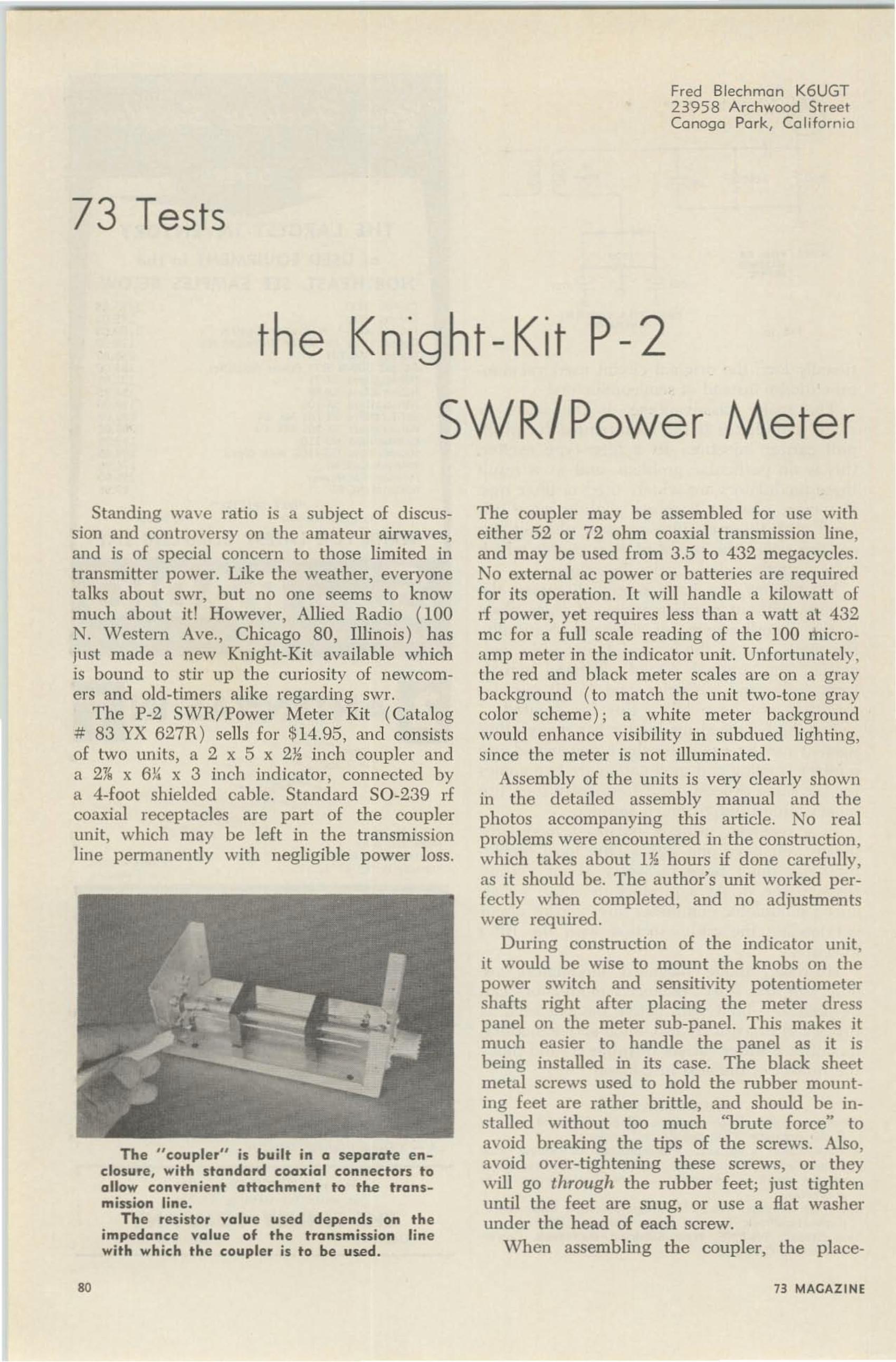
The "coupler" is built in a separate enclosure, with standard coaxial connectors toallow convenient attochment to the transmission line.
Th e resistor value used depends an theimpedance value of the transmission linewith which the coupler is to be used.
80
The coupler may be assembled for use witheither 52 or 72 ohm coaxial transmission line,and may be used from 3,5 to 432 megacycles ,No external ac power or batteries are requiredfor its operation. It will handle a kilowatt ofrf power, yet requires less than a watt at 432me for a fu Il scale reading of the 100 microamp meter in the indicator unit. Unfortunately',the red and black meter scales are on a graybackground ( to match the unit two-tone graycolor scheme); a white meter backgroundwould enhance visibility in subdued lighting,since the meter is not illuminated ,
Assembly of the units is very clearly shownin the deta iled assembly manual and thephotos accompanying this article , No realproblems were encountered in the construction,which takes about 1~ hours if done carefully,as it should be, The author's unit worked perfectly when completed, and no adjustmentswere required.
During construction of the indicator unit,it would be wise to mount the knobs on thepower switch and sensitivity potentiometershafts right after placing the meter dresspanel on the meter sub-panel. This makes itmuch easier to handle the panel as it isbeing installed in its case. The black sheetmetal screws used to hold the rubber mounting feet are rather brittle, and should be installed without too much <brute force" toavoid breaking the tips of the screws. Also ,avoid over-tightening these screws, or theywill go through the rubber feet; just tightenuntil the feet are snug, or use a flat washerunder the head of each screw.
When assembling the coupler, the place-
73 MACAZINE
-- ..~----•- -
---
--_..~T-""L "
2769 CAROLINARED WOOD CITY, CALIf.
P. O. Box 5496Winston-Sa lem, N. C .
No Boo ks To Reali-No VisualGimmicks To Distract You. Just
listen and learnBased on modern ps~hol.. iultechn ioues _ Th i l eourn wi lltakl you beyond 13 w.p.m. In
LESS THAN 0 T HE TIMEAvai lable also on magnetic tape
Ses You r Desler N ow!
l P's 2V2 Hr. Instruction
GROUND RADIALSYSTEM KITS
COLLrnS 1 HAMMARLUND, MOSLEY,SWAN, SIDEBAND ENGINEERrnG,
NATIONAL, GONSET
GENERALIZE YOURSELF !
LEARN RADIO CODETh e EASY JTIA Y
Album
NEW!
Life Story ofNikola Tcsla
Now, learn code and som e
th ing else at the same t ime.
Fa scinating story and code
practice at same t ime. $2.49
EPSILON RECORDS
1. 000 FO OT K IT (10 -60' . S-33'. 8 -17' 1t,\DI.\LS I $24 .9 5
2.000 FOOT K IT (20-60' , 16 -33 ' . ]6-10 ' R.\DI.\L~ 1 $42.95
St'nd cnrr $5.00 (cash. ck .. :-'1. 0 . ) and par balance c o n ptu•ea pre-s OT postage c ha Tg.. ~ vII a rrln l or send f ull pr lre forp r..plli d ol... h ·ery .
n ..re are ground ra d ia l s}'st ..m. for lI:~t tl nll: Improved performanee f rom long-wi re. ~ertklll a nd oth.. r ·' 11 _-\.:\1" and ··~"·L"
a llll'llnll~ .... hlch a re opaat~d a Ra lnst ground, These rad ia l In teres ....111 also Im prove the d rl clenc)' or ongrouude ,! antennassuc h a' doublet. . ze-PI)S lUHI u rrecuce a r ra n Tcd ucl ng the rceseeresutune from ground nonerreeuons. Exce lle nt as p..emau..nl ortempora ry ("' Field 1Ia)' '' ) InsU ll atlvns , Com p le te , re-ady to rollout Tadla l s}'s tems In two d 7. el tv satlsf)" mos t " 11 .\ :-'1· ' a nd" S W L '" requireme nts. 1:. e. :0;0. 14 g auge solid copper ra d ial.... l re1 elect r ically anti m..d lanlca l l}" bonde d to cent ra l huh.Il r h-e pegs are provlded ror . ..r ur lng radi a l .... Ire en<l~, Ju.tlocate cen te r hu b .... I,..re )"uu want It, roll out the rad ials androu're In b usiness . Ila lHa ls ,'an he e a ~II)' buried to prt'SCT\'Cthe Iwa uty or you r f ront or ha" k )'a rd lawn. Yull Imtflu't!uIIIIn kit. Semi rur fr e-e antenna II:ruun<l so-stem tart sheet.
X ow at las t a 2 meter con ver ter comple te w ith 3 VII Ftransis tors and crystal for ou tpu t in the 6 meter band .Operates on 12 V . D .C. A real bargain. for only $ 10.00white supply las ts .F or ou tput in other bands use this wit h our 6 met er
conver t er ad vertised in 7J .
VANGUARD ELECTRONIC LABS Dept. H-5190-48 - 99th Ave. Hollis 23, N. Y.
Take the work out of fabricating yourantenna ground system
CALAMARc~eG.K6HYY
WA6HYU
2J63A FULTON AVE,SACRAMENTQ CAL
.---2 METER CONVERTER- ,
I ~OIC"'TO R V ~ IT
~-kI
r •" "'~?Eo''''''• •
1)1:~..
• - .-• S E ~S
~
• I~T
T
• ~
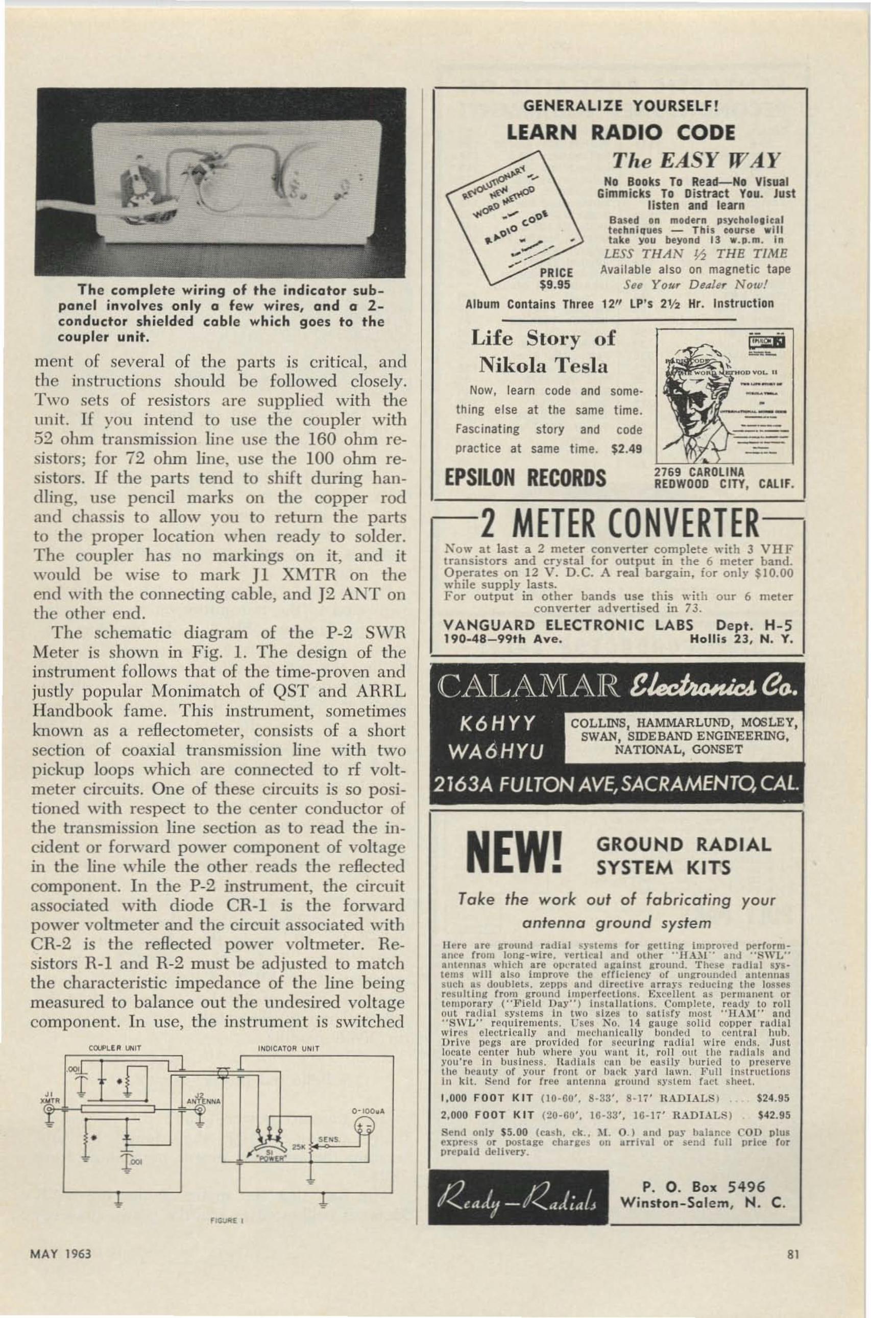
The complete wiring of the indicotor subponel involves only 0 few wires, ond 0 2 conductor sh ielded coble which goes to thecoupler unit.
men t of several of the parts is crit ical, andthe instructions sh ould be followed closely.T wo sets of resistors are supplied with theunit . If you intend to use the coupler with52 ohm transmission line use the 160 ohm resistors; for 72 ohm line, use the 100 ohm resistors. If the parts tend to shift during handling, use pencil marks on the copper rodand chassis to allow you to return the partsto the proper location when ready to solder.The coup ler has no markings on it, and itwould be wise to mark J1 XMTR on theend with the connecting cab le. and J2 A:\'T onthe other end.
The schematic diagram of the P-2 S\VHMeter is shown in Fig. 1. The design of theinstrumen t follows that of the time-proven andjustly popular Monimatch of QST and ARHLHandbook fame. T his Instrument, sometimesknown as a refiectometer, consists of a shortsection of coaxial transmission line with twopickup loops which are connected to rf voltmeter circuits. One of these circuits is so positioned with respect to the center conductor ofthe transmission line section as to read the incident or forward power component of voltagein the line while the other reads the reflectedcomponent. In the P~2 instrument, the circuitassociated with diode CR-I is the forwardpower voltmeter and the circuit associated withC R-2 is the reflected power voltmeter. Resistors R- I and R-2 must be adjusted to matchthe characterist ic impedance of the lin e beingmeasured to balance out the und esired voltagecomponent . In use , the instrument is switched
MAY 1963 81
FANTASTIC BARGAINS ONRECONDITIONED EQUIPMENT!
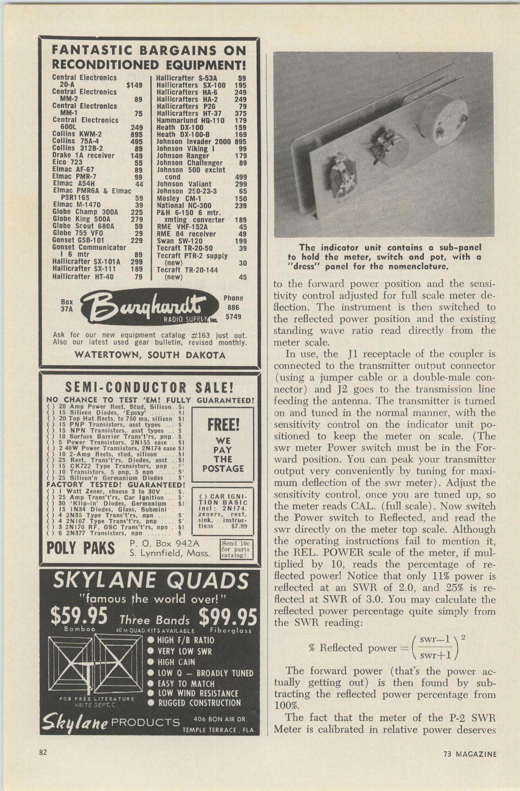
The indicator unit contains a sub-penelto hold the meter, switch and pot, with a"dress" panel for the nomenclature.
tu the forward power position and the sensitivity control ad justed for fu ll scale meter d e.flection. The instrument is then switched tothe reflected power p osit ion and the existingsta nding wave ratio read directly from themeter scale.
In use, the 11 receptacle of the coupler isconnected to the transmitter output connector(using a jumper cab le or a d ouble-m ale connector ) and 12 goes to the transmission linefeeding the antenna. The transmitter is tu rnedon and tuned in the normal man ner, with thesensitivity control on the indicator unit p ositioned to keep the meter on scale. (Theswr meter Power switch must be in the Forward position . You can peak your transmitteroutput very conveniently by tuning for m aximum deflection of the swr meter ) , Adjust thesensi tivity control, once you are tuned up, sothe meter reads CAL. (full scale ). Now switchthe Power switch to ReHected, and read theswr directly on the meter top scale. Althoughthe operati ng instructions fail to m ention it,the REL. POWER scale of the meter, if multiplied by 10, reads the percentage of re·Heeted power! Notice that only 11% power isreflected at an S' VR of 2.0, and 25% is refleeted at SWR of 3 .0. You may calculate th erefiectod p ower percentage quite simply fromth e SWR read ing:
(swr- l )"
% Reflected power =swr-l- I
The forw ard power (that's the power actually getting out) is then found by subtracting the reflected power percentage from100%.
The fact that the meter of the P·2 SWRMeter is calib rated in relative power d eserves
Semi 10"for part~
eata lo.o: l
FREE!WEPAYTHE
POSTAGE
() CAR IGNI _TION BA SiClncl : 2 N 174 .ze ne r s , r ec t ,si nk, f natrue-ttc as $7.99
SEMI·CONDUCTOR
Central Electronics Hallicrafter 5·53A 5'2D-A $149 Hallicratters SX-t 00 195
Central Electronics Hallicrafters HA·6 24'MM·2 89 Hallicrafters HA·2 24.
Central Electronics uantcratters P26 79MM-l 75 Hal1icrafters HT-37 37S
Central Electron ics Hamrnarlund KO·l10 179GOOl 24. Heath OX·, 00 159
Collins KWM·2 895 Heath OX·, 00·8 169Collins 75A·4 495 Johnson InYader 2000 895Collins 3128·2 89 Johnson Viking I 99Drake 1A receiver 14' Johnson Ranger 179EicD 723 .. Johnson Challenger 89Elmac AF-67 89 Johnson 500 excmtElmac PMR·7 99 cand 499tunae A54H 44 Johnson Valiant 299runae PMR6A & Elmac Johnson 25:0-23-3 65
PSR116S .. Mosley eM·' 15.Elmac M·1470 39 National Nt·300 239Globe Champ 30DA 225 P&H 6·150 6 mlr.Globe King SODA 279 xmting converter 189Globe Scout GaDA .. RME VHF·1S2A 45Globe 755 VFO 29 RME 84 receiver 4.Gonset GSB·101 229 Swan SW·120 199Gon set Communicator Tecraft TR·20-50 39
I 6 mtr 89 Tecraft PTR·2 supplyHallicrafter SX·1 01 A 299 (new) 3.Hallicrafter sx-ti t 189 Tecraft TR-20·144Hallicrafter HT-40 79 (new) 45
." Phone
37. BB'5749
Ask for our new equipment catalog # 163 just out.Also our lat est used gear bulletin, revised monthly.
WATERTOWN, SOUTH DAKOTA
SAL E!NO CHANCE TO TEST ' EM ! FULLY GUARANTEED I( ) 20 Amp Power Rect . Stu d, S il icon " $1( ) 15 Silicon Diodes, ' Epoxy' _, _. _ !' I( ) 20 Top Hat Rects . t o 750 rna, s i li con $1() 15 P NP T ransi st ors, asst t ypes ... 5() 15 NPN Transistors , asst types 5() 10 Surface Barrier Trans ' t 'rs , pnp $() 5 Power T ransistors , 2NI55 cas e SI( ) 2 40W Power T ransistor s, 2NI 74 cas e $1( ) 10 2· Amp Heet s, st ud, si li con, . . . ,S I( ) 25 Red , Trans't' r s. tneoes. asst . $1( ) 15 CK722 Type T ransi stors, pnp . ~..() 10 Transi st ors. 5 pnp, 5 npn . , ... ~ '
() 25 Sil icon'n Ger maniu m DIodes $ 'FACTORY TESTED! GUARANTEED!( ) I Watt Zener , choose 3 t o SOY . , s,() 25 Amp Tran s't'rs, Car Ignition S'( ) au ' Klip- in' Diodes, Gflrm anium $1( ) IS I N34 Diodes, Glass, Submini() 4 2N35 Type Trans ' t 'rs , npn ... _ S'() 4 2NI07 Type 'rrees't'rs. pnp s:( ) 3 2N170 RF , OSC Tr ans't'rs. npn $ 1( ) 6 2NSn Transistors , nun .' $ '-:--,~;:;:;:;;:i'
P. O. Box 942AS. Lynnfield, Mass.POLY PAKS
" 73 MAGAZINE

TV CAMERA
CONVERTER SALE
Basic
Parts
Kit
and up
$99.50
••
HUNDREDS OF TOP OUALITYITEMS-Heceh'"e rs. TTans.mllterll.
Microphones. I nverters. Power S UpDllffi. l l eu ·fI. Phones. Antennas. ted tcetore, Filters. T ra.nstormers. A mplifie rs. n e" dsets, eonverteN., ConlrolHOIH . Dyna motors. Test EquIpment.Motors . Illower'll, Ca ble. KeyefS.Chokffi. n and llets. Switebes. etc.. etc.8 end (or Jo' fE'e Catalog-Ikpt. 73.
L 0 0 KBC_221 Frelt Mete r wit h orl • . ea llb. book and xta t,li b checked out. XL:S·.r condo . , .... _. _ $69 .50Crystal Oven-BlI ley crnu l I labil izer . type TeO -lfor l H C/6 CrYst ll. n eouuee 6.3v at 0.85 a. I %," d ta.x ll,l," ocUI plug i n bale. Ill lAND NEW . . ," . $2.7585 kc if Translorm erl-lllla reS tor AHC·12. Same aslIC-453 with ceramic bas e & air tetmmers excepthlMher "Q" & diff erent base vlns. B RAND NEW
79c ea. 3/$2.25RF Crys ta l ProbeS-lor VO.U with KlIpzon tips ,made by Genera l Cement. Lis t f,4.35, nUAKD NEWIn ceuo. bag ,. _. '" $1. 25Su per Midget Relay- ] ' &B ~M -50 S . lIerm. sealedptua-In, fit 1 pin min. tube eockct , S P DT . 250 rnaeentect s. Coil 6 vde. 811 ohms . , $1. 25A RT- 13 Calib. Cmtals. 20 0 ke. herm. sealed wlatta lplug-In base '". '" ,". . '". _. '" $1. 50
Write for Bulletin #38 "loads of Bargains"R. W. Electronics, Inc.
Mlchi . an A¥t. Oeot. 755 Chicago 16. llIinollPhone ; CAlumet 5· 1281
2430 South
IMPROVED VHF-UHF RESULTSJ Beam Skele ton S101l tor 50.144·220-432 n e.
'rremendcus fe l ultS at mode ra te costl.Speclals
300 to 52 ohm waterproof ba lunl-83 connector! 50·54 melraeyelel$1 0. 75 : 141-148 meglcycle. $8 .60
HG 8U Klme B rand Polyfoam I nsujated cable ft. . 15fOR THE OX BOYS
G4Z U Mlnlbeaml In-15-20 A II)\\'. loW $74 .9 5BE PROUD Of YOUR SIGNAL
GAIN, Inc., D ept . 73 ·5, 1209 W est 74,Chicago 30 P h.: 874 aero
Deta ils-FREE List #771DENSON ELECTRONICS CORP.
Rockville, Connecticut
6 meter ecneerte r $8. 00 pottpald.. Comple te III' lth 3 bleh treQuelKJ tfans lston and 49.4 me. ennal tor out put in broadc:a.nband or 36 me. crYltal for outpu t in 14-18 me. band. lAwnoise and better t ha n I mlC1'OTOIt lenaitirt tJ'. Operatel on 6-l tV D.C.
LImited quantity-send your order today.VANGUARD ELECTRONIC LABS Dep•. H-5190-4B-99th Ave. HollIs 23, N. v-
some explanation. The reHectomctcr type ofSWR meter is quite dependent on frequencyfor any given output indication. Note that 45watts is required for full scale deflection at 1.8me while only ~ watt is required for full scaledeflection at 432 me. This ratio is perfectlynormal for this type of meter. However, it prevents the inclusion of absolute power scales inan all band instrument. Despite this , the relative power scale is quite convenient for transmitter tuning, etc.
The calibration of the completed unit maybe checked several ways. The instructions gothrough an alignment procedure which requires a non-reactive dummy load. At the higher frequencies and for high power this mightpose a problem. A simple way to make aquick check is to reverse the coupler in thetransmission line, connecting J2 to the transmitter output, and Jl to the transmission line.Now set CAL on the met er with the Powerswitch in the Reflected position , and read swrin the Forward position . If the same swr isobta ined as using the coupler the correct way,the unit is well balan ced. If not, the positionof the diode connect ions to the pick-up wiresin the coupler must be adjusted slightly, asdescribed in the manual. The author's unitrequired no adjustments.
Be careful about quoting your swr readingswith too much certainty. You see, it just sohappens that the SW f rend at the transmitteris always lower than the actual swr at thetransmitter. The reason is simple: the forwardpower is a ttenuated on its way to the antennaby line loss, and the power reflected at theantenna is also attenuated by the transmissionline on its way back to the transmitter. Therefore, the percentage of reflected power reaching the swr meter is less than it should be,compared to the ou tgoing forward power.
The meter is calibrated to SWR of 20.The lower sca le, multiplied by 10, readspercent reflected power. For example, atSWR of 3, 25 % power is reflected fromthe load.
MAY 1963 83
A typical "neat" station !
4
~ >•>x••~ 2
~~•~
O' fWZ '3 4 5 6
NO RMAL LINE LOSS AT SWR - I: I
FIGURE 2
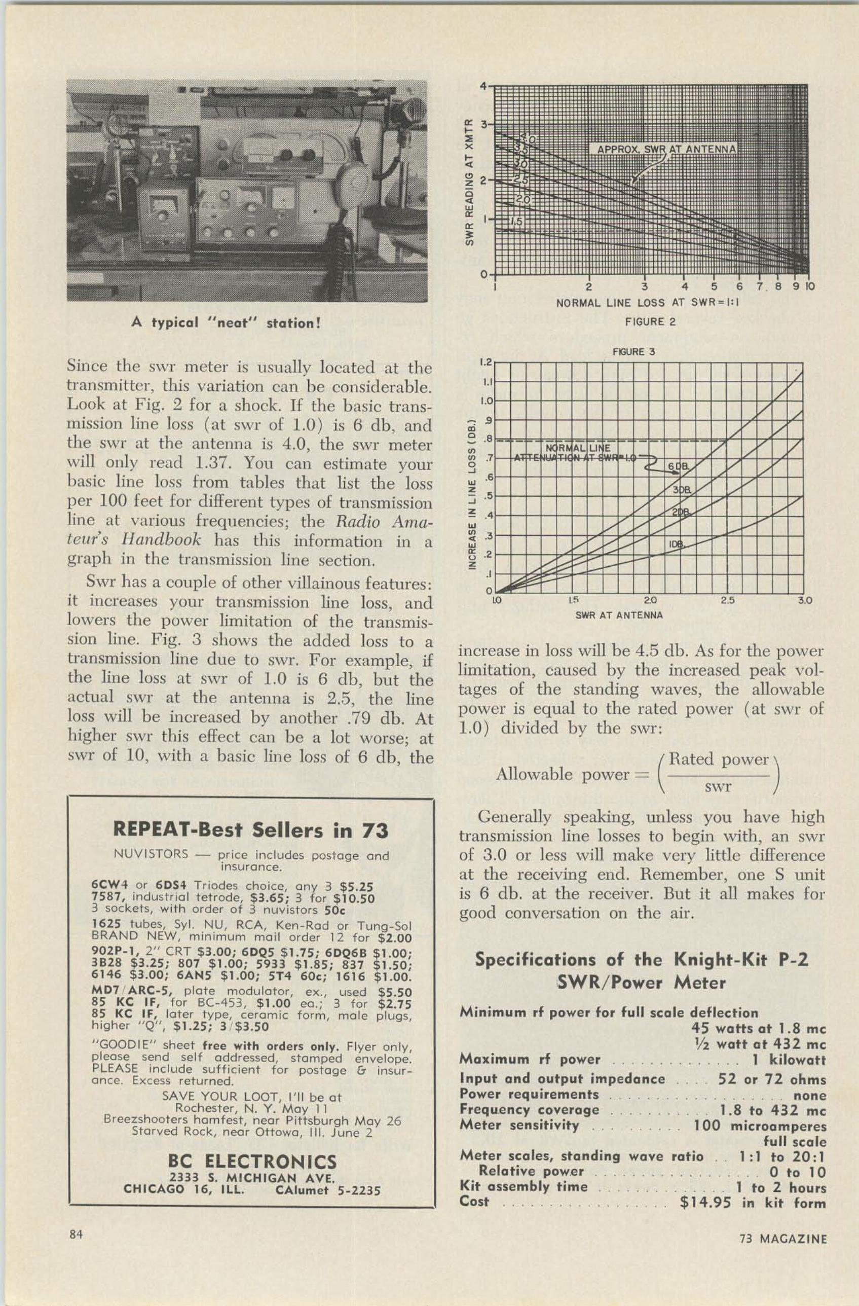
increase in loss will be 4.5 db. As for the powerlimitation, caused by the increased peak voltages of the standing waves, the allowablepower is equal to the rated power (at swr of1.0 ) divided by the swr:
(Hated. power )
Allowable power =swr
FGURE 3
Since the S\\T meter is usua lly located at thetransmitter, th is variation can be considerable.Look at Fig. 2 for a shock. If the basic transmission line loss (at swr of 1.0 ) is 6 db, andthe swr at the antenna is 4 .0, the swr meterwill onlv read 1.37. You can estima te vour
• •basic line loss from tables that list the lossper 100 feet for d ifferent types of transmissionline at various frequencies; the Radio Amateur's Ilandbook has this information in agraph in the t ransmission line section.
Swr has a couple of other villainous features :it increases your t ransmission line loss, andlowers the power limitation of the transmission line. Fig. 3 shows the added loss to atransmission line due to swr. F or example, ifthe line loss at swr of 1.0 is 6 db, but theactua l swr at the antenna is 2..5, the lineloss will be increased by another .79 db. Athigher SW I" this effect can be a lot worse; atswr of l O, with a basic line loss of 6 db, the
aoSWR AT ANTENNA
v
"
v
' .0
Meter scales, standingRelative power
Kit assembly timeCost .
Specificatians af the Knight-Kit P-2SWR/Pawer Meter
Minimum rf power for full scale deflection45 watts at 1.8 meV2 watt a t 432 me
. .. 1 kilowatt52 or 72 ohms
. . . . . none1.8 to 432 me
100 microamperesfull scale
wave ratio , 1 :1 to 20 :1. . . . . 0 to 10. . .. 1 to 2 hours
. $14.95 in kit form
Generally speaking, unless you have hightransmission line losses to begin with, an swrof 3.0 or less will make very litt le differenceat the receiving encl . Remember, one S unitis 6 db. at the receiver. But it all makes forgood conversation on the air.
Maximum rf power ....Input and output impedancePower requirements .Frequency coverage . .Meter sensitivity ..
BC ELECTRONICS2333 S. M ICHIGAN AVE.
CHICAGO 16, ILL. CAlumet 5-2235
NUVI5TQRS - price includes postage andinsurance.
6CW -I or 60H Triod es choice. any 3 $ 5. 2 575 87, industrial tetrode, $ 3.65 ; 3 fo r $ 10.503 sockets, with order of 3 nuvistors 50c1625 tubes, Svl. NU, RCA, Ken-Rod or Tung-SolBRA ND NEW, minimum mail order 12 for $ 2 .009 02 P_ l , 2" CRT $3.00; 6DQ5 $ 1.7 5: 60Q6B $ 1.00 ;3B28 $ 3. 25 ; 807 $ 1.0 0 ; 5933 $1.85: 8 37 $ 1. 50 ;6146 $ 3.00 ; 6A N5 $ 1.0 0 ; 5T4 60e: 1616 $ 1.00.M07 /ARC-5, plate modulator, ex ., used $ 5.508 5 KC IF, for BC-453, $ 1.00 ec.: 3 for $2 .7585 KC IF, later type, ceramic fo rm , male plugs,higher "Q", $ 1.2 5: 3 / $3 .50
"GOODIE" sheet f ree with orders only. Flyer only,please send self a ddressed , stamped envelope.PLEASE include sufficient fo r postage & insurance. Excess returned.
SAV E YOUR LOOT, I' ll be atRochester, N. Y. Ma y 1 1
Breezsbooters ha m fest, near Pittsburgh Ma y 26Starved Rock, near Ottowa, Il l. J une 2
REPEAT-Best Sellers in 73
84 73 MACAZINE