THE KELLOGG COAL GASIFICATION PROCESS archive/Files/Volumes... · sodium carbonate system used for...
86
-1- THE KELLOGG COAL GASIFICATION PROCESS A. E. Cover, W. C. Schreiner, G. T. Skaperdas The M. 'W. Kellogg Company, Houston, Texas 77027 r I. INTRODUCTION The Kellogg Molten Salt Coal Gasification Process represents a unique approach to the problem of coal gasification. The molten sodium carbonate system used for heat supply and catalysis in the Kellogg Coal Gasification Process provides the following advantages. The strong catalytic action for the steam-carbon reaction and coal combustion reaction makes it possible to carry the overall gasification to essentially complete conversion of coal leaving very little fuel to be rejected with the ash. Heat can be supplied by air or oxygen combustion of coal or char from the molten salt, and, in the case of oxygen, it is possible to keep the combustion Products separated from the synthesis gas. This has the advantage of keeping sulfur oxides out of the flue gas stream and, in addition, it eliminates carbon oxide dilution of the synthesis gas stream. Examination of the basic process chemistry and the effect of pressure on the process economics has shown that the Kellogg process is improved by operation at 1200 psia rather than at 400 psia as in the original concept. Operation at high pressure ' and the separation of the gasification zone from combustion zone makes it possible to take full advantage of the catalytic effect of the molten salt on the direct production of methane from synthesis gas in the gasification step. This is important because it will minimize the heat supply requirement thereby yielding improved economics. In this process, steam and fine coal are injected continuously into a molten salt bath where they react to form synthesis gas C + H20 + heat + H2 + CO according to Reaction (1): , ( (1) (coal) (steam) (synthesis gas). The necessary heat of reaction is supplied by circulating a heated salt stream. In addition, the molten salt mixture is chosen to catalyze Reaction (1) so that it may be carried out at a relatively low temperature. Savings result from the lower reaction temperature, which minimizes the heat demands of the process. The lower reaction temperature also.results in a larger concentration of methane in the synthesis gas, which is a decided advantage in the manufacture of pipeline gas. The result is lower investment and lower operating costs.
Transcript of THE KELLOGG COAL GASIFICATION PROCESS archive/Files/Volumes... · sodium carbonate system used for...

- 1 -
THE KELLOGG COAL GASIFICATION PROCESS
A. E. Cover, W. C. Schreiner, G. T. Skaperdas
The M. 'W. Kellogg Company, Houston, Texas 77027 r
I. INTRODUCTION
The Kellogg Molten Salt Coal Gasification Process represents a unique approach to the problem of coal gasification. The molten sodium carbonate system used for heat supply and catalysis in the Kellogg Coal Gasification Process provides the following advantages. The strong catalytic action for the steam-carbon reaction and coal combustion reaction makes it possible to carry the overall gasification to essentially complete conversion of coal leaving very little fuel to be rejected with the ash. Heat can be supplied by air or oxygen combustion of coal or char from the molten salt, and, in the case of oxygen, it is possible to keep the combustion Products separated from the synthesis gas. This has the advantage of keeping sulfur oxides out of the flue gas stream and, in addition, it eliminates carbon oxide dilution of the synthesis gas stream.
Examination of the basic process chemistry and the effect of pressure on the process economics has shown that the Kellogg process is improved by operation at 1200 psia rather than at 400 psia as in the original concept. Operation at high pressure '
and the separation of the gasification zone from combustion zone makes it possible to take full advantage of the catalytic effect of the molten salt on the direct production of methane from synthesis gas in the gasification step. This is important because it will minimize the heat supply requirement thereby yielding improved economics.
In this process, steam and fine coal are injected continuously into a molten salt bath where they react to form synthesis gas
C + H20 + heat + H2 + CO
according to Reaction (1): , (
(1) (coal) (steam) (synthesis gas).
The necessary heat of reaction is supplied by circulating a heated salt stream. In addition, the molten salt mixture is chosen to catalyze Reaction (1) so that it may be carried out at a relatively low temperature. Savings result from the lower reaction temperature, which minimizes the heat demands of the process. The lower reaction temperature also.results in a larger concentration of methane in the synthesis gas, which is a decided advantage in the manufacture of pipeline gas. The result is lower investment and lower operating costs.
- 2 -
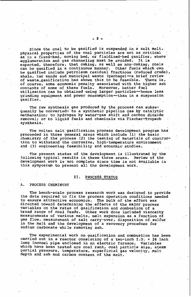
Since the coal to be gasified is suspended in a salt melt, physical properties of the coal particles are not as critical as in a fixed-bed, moving bed, or fluidized-bed gasifier, where agglomeration and gas channeling must be avoided. expected, therefore, that caking, as well as non-caking, coals can be gasified in a continuous manner. Other fuels which can be gasified include petroleum residual fractions (reduced crude), shale, tar sands and municipal waste (garbage)-a brief review of waste_gasification has shown this to be feasible. There is, of course, some economic penalty associated with the higher ash contents of some of these fuels. Moreover, better fuel utilization can be obtained using larger particles-hence less grinding equipment and power consumption-than in a suspension gasifier.
quently be converted: to a synthetic pipeline gas by catalytic methanation; to hydrogen by water-gas shift and carbon dioxide removal; or to liquid fuels and chemicals via Fischer-Tropsch s ynthe si s .
It is
The raw synthesis gas produced by the process can subse-
The molten salt gasification process development program has proceeded in three general areas which include (1) the basic chemistry of the process ( 2 ) the testing of materials of contruc- tion to withstand the corrosive, high-temperature environment and ( 3 ) engineering feasibility and economic studies.
The present status of the development is illustrated by the following typical results in these three areas. Review of the development work is not complete since time is not available in this symposium to present all the development work.
11. PROCESS STATUS
A. PROCESS CHEMISTRY I
The bench-scale process research work was designed to provide the data required to fix the process operation conditions needed to ensure attractive economics. The bulk of the effort was directed toward determining the effects of the major process variables on the rates of gasification and combustion o f a broad range of coal feeds. Other work done included viscosity measurements of various melts, melt expansion as a function of gas flow, measurement of salt carry-over, disposition of sulfur in the melt and the development of a recovery procedure for sodium carbonate while removing ash.
carried out in a reactor consisting of a two-inch I . D . x 26 inch long Inconel pipe enclosed in an electric furnace. Variables which have been tested are coal rank, coal particle size, steam partial pressure, temperature, superficial gas velocity, melt depth and ash and carbon content of the melt.
The experimental work on gasification and combustion has been

- 3 - .
The activation energies for various ranks of coal have been found to vary from 5300 cal/mole for Renner’s Cove lignite to 28,600 for anthracite. The gasification rate was found to increase with the 0.55 power of the steam partial pressure and favorable effects on the gasification rate were also found with increasing gas velocity and ash content. The rate is first order with respect to carbon content of the melt but the gasification rate was found to decrease with increasing melt depth. Further gasification tests are planned in the larger, 1200 psi vessel described in the next section on materials testing.
The combustion rate was similarly found to be first order with carbon content but no effect of air pressure or velocity was found. Finer size of coal particles was found to increase the combustion rate and the addition of 0.5% Na2S increased the rate by a factor of four. Once again, increasing melt depth was found to reduce the combustion rate. The combustion efficiency to C02 has been measured to be greater than 85%. Studies on the disposition of sulfur in the process have shown that the flue gas will contain very little sulfur compounds. -
B. MATERIALS TESTING
The molten salt system has presented a severe containment problem. Previous work on corrosion of test specimens has shown
satisfactory corrosion resistance and can serve well as a vessel lining. The corrosion tests have included all the components that will be in the reactor under commercial operating conditions, including coal ash, coal sulfur, the sodium-sulfur compounds in the appropriate state of reduction and oxidation as well as coal particles undergoing gasification. In addition corrosion tests of Monofrax A were conducted with test pieces that were spring loaded to compressive stress levels that would exist in the wall of a full-scale commercial vessel. These tests showed clearly that Monofrax A would resist the attack of the reacting system including design stresses in a completely satisfactory manner.
I that Monofrax A (a fused, cast, high-purity alumina) provides
’
Vessel designs were carried out in sufficient detail to ensure that dependable vessels could be built using a Monofrax A lining. proper control of temperature gradients through the wall, and designs incorporating such gradient control were found to be entirely practical. It has become necessary to demonstrate the validity of the conclusions from the corrosion test program and the vessel design work and thus to demonstrate the validity of the ,design for the containment problem. For demonstration purposes, a corrosion test vessel has been designed.
The mortar in the wall will be frozen salt necessitating
It is expected that this corrosion test unit will, when commissioned, provide proof of feasibility of the commercial design concept. The test vessel chosen is six inches diameter by six feet long and the heat is supplied by combustion of fuel

- 4 -
to produce a simulated synthesis gas. This permits establishment and demonstration of the temperature gradients essential to the design, and avoids the very high cost of a melt circulation system. The fuel chosen is propane which is burned with air at full process pressure. Steam, hydrogen sulfide and coal ash are added to the system to simulate the "working" salt conditions that would be encountered in actual coal gasification.
III. PROCESS DESCRIPTION
Based on the experimental work carried out on the process, a flow sheet for a plant to produce 262,000,000 standard cubic feet per day of 956 Btu/SCF pipeline gas has been prepared. The gasification section of this plant is shown in Figure 1. This flow sheet design work has had the objective of determining the economic attractiveness of the process; some items (e.g., coal feeding) may be modified on further design work. Ground coal is added to one of the coal lock hoppers and is pressurized with an inert gas or with compressed synthesis gas. Coal is with- drawn continously from the pressurized hopper (while the other - hopper is being filled) into to stream of steam at 1500'F and 1250 psia. Steam and coal are injected into the molten salt gasifier where they are heated by intimate contact with the molten salt (sodium carbonate) and react according to Reaction (1) to produce synthesis gas. The synthesis gas leaves the molten salt bath at about 1750OF and 1200 psia, flows through a heat exchanger where the sensible heat of the gas is used to generate steam, is quenched with water and is delivered at 7 O O O F ' for further processing.
In the molten salt gasifier where Reaction (1) takes place, a circulation of molten salt is used to supply the needed heat. This heat is generated in a separate combustion vessel where some of the coal in the melt is burned with oxygen which heats the melt. Melt circulation is accomplished using the gas lift principle where steam is used to aerate and lift the molten salt from the combustor to the gasifier. Flow from the gasifier back to the combustor is by gravity.
The flue gases which heat the melt by direct contact are generated by combustion of coal with oxygen. Oxygen for this purpose is compressed to 1230 psia and is preheated against the flue gases leaving the combustor. The flue gases flow through the expander which provides the power needed for oxygen compres- sion and then flow to the ash removal section where the COZ is used to recover the Na2CO3.
It should be noted at this point that the two-vessel, gasifier-combustor system shown in Figure 1 is but one of the possible designs which are being considered. One alternate is a single-vessel system where the oxygen is fed directly to the gasifier. results in reduced methane production in the gasifier and some- what higher operating costs.
This scheme eliminates the circulating melt but

- 5 -
Ash the coa
left in the melt by is allowed to buil,
the combustion and gasification of up to a level of 8 weight percent
and settled in a quiescent zone to 16 percent ash. A stream Of the ash-carbon-sodium carbonate mixture is continuously withdrawn from the gasifier and flows to ash removal where it is processed to separate the ash from the melt. A simplified flow sheet for this ash removal is presented as Figure 2. The melt stream is quenched to 400°F with a solution saturated with sodium bicarbonate at 100°F in the quench tower. Solid melt particles in the result- ing slurry are ground to facilitate dissolution of the salt. This stream is then flashed to essentially atmospheric pressure into a holding tank, where sufficient residence time is provided to dissolve the sodium carbonate. The slurry leaving this vessel is filtered to separate the ash and carbon from the solution. This residue is sent to disposal.
The solution leaving the filter flows to a carbonation tower where the sodium carbonate is reacted with carbon dioxide from the gas purification system. The tower operating temperature is about 100OF. At this temperature the sodium bicarbonate concentration exceeds its solubility limit and it is precipitated from solution. The slurry is then filtered, the bicarbonate leaving the filter is calcined to decompose the bicarbonate to carbonate and is returned to the combustor while the solution is recycled to the quench tower.
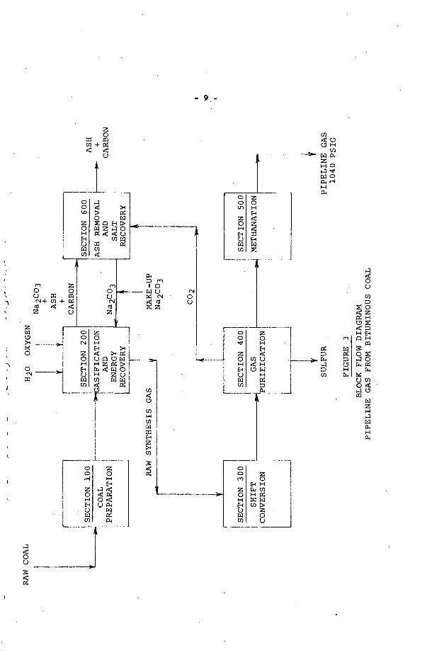
Raw synthesis gas delivered from the synthesis section is further processed as shown in Figure 3. The gas is shifted to adjust the ratio of hydrogen to carbon monoxide for optimum methanation, and is then purified and finally converted to methane.
IV. ECONOMICS
The equipment needed to carry out the primary process steps just described as well as all auxiliary equipment needed to supply additional services and controls have been designed for a plant to produce 262,000,000 standard cubic feet of 956 Btu/SCF pipeline gas and the plant cost has been estimated.
Estimated capital investment is summarized in Table 1. Offsite Facilities, Section 1100, encompasses all those facilities needed to make the plant completely self-sufficient, such as fire- fighting equipment, buildings to house administrative and support- ing personnel, and equipment to supply steam, electric power and cooling water. Total capital investment for the plant is about $149,000,000. This investment is for a "turn key" plant-that is, one which is completely erected and ready for full operation-and includes the contractor's overhead and profit for the complete engineering and construction of the plant.
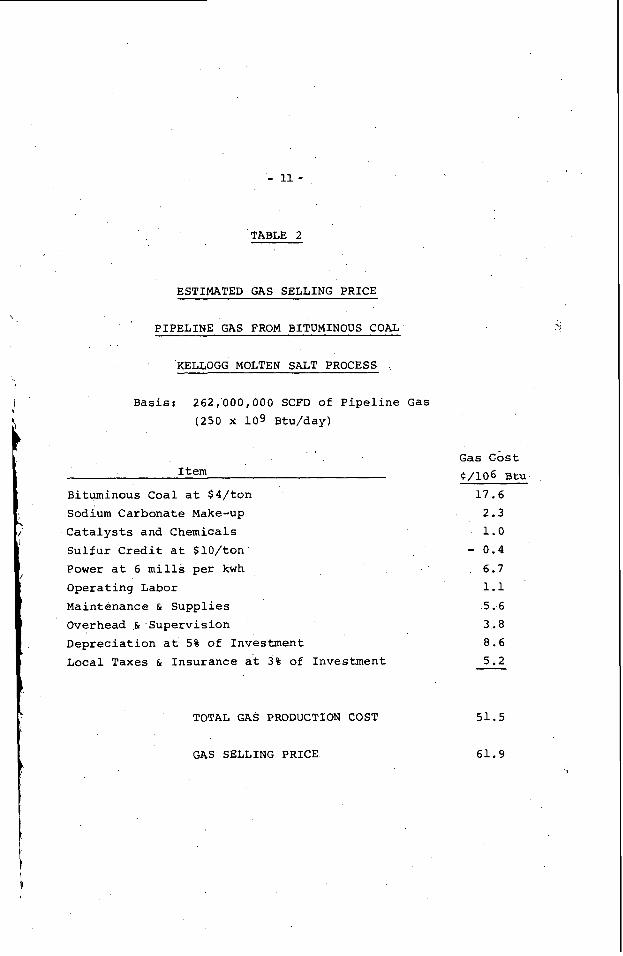
Estimated gas manufacturing cost and selling price are shown in Table 2. With bituminous coal charged at a nominal $4 per ton and depreciation at 5 percent per year, estimated gas roduction cost, before any return on investment, is about 52C/10B Btu. Using the AGA-IGT Utility Accounting Method which assumes 65/35
- 6 -
debt-equity ratio, 5% interest on the outstanding debt, 4 8 % income tax rate and 7 % return on the utility rate base, th? twenty-year average gas selling price is 62C/106 Btu. With a 7 . 5 % interest rate and 9 % return, the gas eelling price would be about 65C/MM Btu.
It is therefore concluded that the Kellogg Coal Gasification Process is an economically attractive process for the production of substitute natural gas. Operation of the gasifier at 1200 psia maximizes the direct production of methane thereby reducing the heat supply requirement (and oxygen requirement) and improving the economics. A comparison has shown that the heat requirement' in the gasifier is reduced by 4 4 0 at 1200 psia vs. 400 psia. Also, over 99% of the carbon in the coal is converted to synthesis gas owing to the strong catalytic action of the salt on the steam-carbon reaction and the coal combustion reaction, as well as on the coal hydrogenation reaction. For the above reasons, it is felt that further development of this process as an alternate substitute natural gas process or as a synthesis gas or hydrogen producer for hydrogasification or other uses is warranted.

z W u >I X 0
.-I
2 2
' 3
1 E
. . rd z
.. .
z 0 H El V w m z El
H E H VI 4 c3 P: 0 : E
E 5

- 8 -
t
tx
E 0 0 0 r(
hl
1 I
0" u X rd z
X " 4 p: 0 E
- 9,-
4- 2 W u
0
$ I
0 0
I
.--4 X
0 0 4
L---t
n 0 V
I -... 1
--I .
!

- 10 -
TABLE 1
INVESTMENT SUMMARY
PIPELINE GAS FROM BITUMINOUS COAL
XELLOGG MOLTEN SALT PROCESS
Basis: 262,000,000 SCFD of Pipeline Gas (250 x lo9 Btu/day)
Section Title INVESTMENT
100 Coal Storage and Preparation 200 Gasification
Oxygen Plant 3 0 0 Shift Conversion 400 Gas Purification 500 Methane Synthesis 6 0 0 Ash Removal 1100 Offsite Facilities
< $ 5,100,000 39,100,000 30,600,000 10,000,000 22,100,000 4,300,000 13,200,000 18,000,000
TOTAL FIXED INVESTMENT $142,400,000
Working Capital 6,800,000
TOTAL CAPITAL INVESTMENT $149,200,000
- 11 -
TABLE 2
ESTIMATED GAS SELLING PRICE
, PIPELINE GAS FROM BITUMINOUS COAL
KELLOGG MOLTEN SALT PROCESS
B a s i s : 262 ,000 ,000 SCFD of P i p e l i n e G a s
(250 x l o 9 Btu/day)
I t e m
B i tuminous C o a l a t $ 4 / t o n Sodium C a r b o n a t e Make-up
C a t a l y s t s a n d C h e m i c a l s
S u l f u r C r e d i t a t $ l O / t o n
Power a t 6 m i l l s per kwh
O p e r a t i n g L a b o r
M a i n t e n a n c e & S u p p l i e s
Overhead & S u p e r v i s i o n
D e p r e c i a t i o n a t 5% o f I n v e s t m e n t
Local T a x e s & I n s u r a n c e a t 3% of Investment
TOTAL GAS PRODUCTION COST
GAS SELLING PRICE
G a s C o s t
$/lo6 Btu 1 7 . 6
2.3 1.0
- 0.4 6.7 1.1 -5.6 3.8 8.6 5 .2
5 1 . 5
61 .9
i
!

STAWS AND DESIGN CHARACTERISTICS OF . THE BCR/OCR BI-GAS PILOT PLANT
BY J. F. Farnsworth* and R. A. Glenn*
I. INTRODUCTION
Research and development w'as initiated in 1965 on the generatian of data required for the design of a pilot plant for the production of high- Btu pipeline gas based on the concept of two-stage super-pressure entrained gasificatitm of coal. successively through three levels of scale-up and has now reached the point where operation of a fully integrated coal-to-pipeline gas pilot plant is considered to be the next logical step in the develqment of the process.
Experimental work on the program has progressed
Initial experiments were conducted in rocking autoclaves using 5- gram charges of coal. a high yield of methane could be obtained directly from coal by reaction with steam at elevated temperatures and pressures.(l)w Flow experiments in an externally-heated reactor confirmed the assumption that higher meth- ane ylelds could be obtained from coal entrained in steam-synthesis gas mixtures at short residence times.(l) fired 100 lb/hr flow system has further confirmed the basic principle and advantages of the two-stage super-pressure concept, and has provided design data for the integral two-stage gasifier.(2)
coal-to-pipeline gas pilot plant based on a 5 ton/hr two-stage, super- pressure, entrained oxygen-blown gasifier, otherwise designated as the
Resultant data confirmed the basic assumption that
Recent work in an internally-
r
This paper presents the design characteristics of a fully integrated
BCR/OCR BI-GAS PROCESS.
11. BASIC PRJXCTPLES AND ADVAHTAGES OF THE BI-GAS PROCESS
A. Basic Principle of BI-GAS Process
In the two-stage super-pressure gasification process( 3) , fresh pulverized coal is introduced into the upper section (Stage 2) of the
* Project Nsmger, Kappers Company, Inc., Pittsburgh, Pennsylvania
Assistant Director of Research, Bituminous Coal Research, Inc., Monroeville , Pennsylvania
H-E Numbers in parenthesis indicate references listed under "Literature cited.
- 13 -
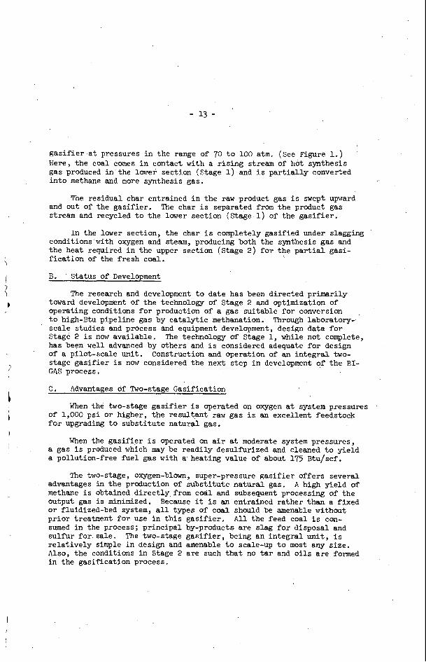
gas i f i e r a t pressures i n the range of 70 t o 100 atm. (See Figure 1.) Here, the coal comes i n contact with a r is ing stream of hot synthesis gas produced i n the lower section (Stage 1) and i s pa r t i a l ly converted i n t o methane and more synthesis gas.
The residual char entrained i n the raw product gas i s swept upward !She char i s separated from the product gas and out of the gasif ier .
stream and recycled t o the lower section (Stage 1) of the gasif ier .
In the lower section, the char i s completely gasified under slagging conditions with oxygen and steam, producing both the synthesis gas and the heat required i n the upper section (Stage 2 ) fo r the p a r t i a l gasi- f icat ion of the fresh coal.
B. Status of Development
The research and development t o date has been directed primarily toward development of the technology of Stage 2 and optimization of operating conditions f o r production of a gas suitable fo r conversion t o high-Btu pipeline gas by catalyt ic methanation. scale studies and process and equipment development, design data f o r Stage 2 i s now available. has been well advanced by others and i s considered adequate f o r design of a pilot-scale unit. Construction and operation of an integral two- stage gasif ier i s now considered the next step i n development of the BI- GAS process.
. Through laboratory-
The technology of Stage 1, while not complete,
C. Advantages df Two-stage Gasification
When the two-stage gasif ier i s operated on oxygen a t system pressures of 1,000 psi or higher, the resultant raw gas i s an excellent feedstock for upgrading t o subst i tute natural gas.
When the gas i f i e r i s operated on a i r a t moderate system pressupes, a gas i s produced which may be readily desulf’urized and cleaned t o yield a pollution-free f u e l gas with a heating value of about 175 Btu/scf.
advantages i n the production of subst i tute natural gas. methane i s obtained d i r ec t ly from cod1 and subsequent processing of the output gas i s minimized. or fluidized-bed system, a l l types of coal should be amenable without pr ior treatment fo r use in t h i s gasif ier . All the feed coal i s con- sumed i n the process; principal by-products are slag f o r disposal and sulfur fo r sale. The two-stage gas i f i e r , being an integral un i t , i s re la t ively simple i n design and amenable t o scale-up t o most any s ize . Also, the conditions in Stage 2 are such tha t no t a r and o i l s a r e formed in the gasification process.
The two-stage, oxygen-blown, super-pressure gas i f i e r offers several A high yield of
Because it i s an entrained rather than a fixed
I ,

- 14 -
111. DESCRIRION OF BI-GAS PILOT PLANT '
For the past two years, planning has been underway fo r the further development of two-stage gasification. The plans include a much broader concept than the erection and operation of a pilot-scale gas i f i e r . Inas- much as the equipment, personnel, and other f a c i l i t i e s necessary for the p i l o t testing of t h e BCR two-stage process w i l l be usable i n the solution of problems related t o other gasification processes under development, it appears prudent t h a t a broader view should be taken i n planning of pi lot- plant research.
Further stimulating t h i s concept i s the growing interest i n the development of a new approach t o power generation incorporating coal gasification at the power s ta t ion; t h i s approach would use an air-blown rather than an oxygen-blown gas i f i e r , followed by large high-temperature gas turbines.
Early discussions with the Office of Coal Research resulted i n the concept of a multipurpose research integrated f a c i l i t y , and a technical evaluation and cost estimate of such a n integrated research f a c i l i t y was made w i t h the assistance of Koppers Company, 1nc.f )
The research f a c i l i t y a s currently planned 1 / 11 ultimately embody alternate systems for each of the major u n i t operations i n the conversion of run-of-mine coal, o r char, t o high-Btu pipeline gas; t o sulfur-free, low-Btu fuel gas; t o industr ia l gases; and t o MHD fuel gas. Three types of gasification un i t s w i l l be provided: an air-blown, medillm-pressure, two-stage gas i f i e r ; an oxygen-blown, super-pressure, two-stage gas i f i e r ; and a low-pressure, multi-stage, fluidized-bed gas i f i e r .
The i n i t i a l p i l o t plant i s now being designed for the multipurpose research p i l o t plant f a c i l i t y (MPRF); it is based on the oxygen-blown version of the two-stage gas i f i e r and w i l l include a l l f a c i l i t i e s needed for converting coal into high-Btu pipeline-quality gas. (5) t o t he basic gas i f i e r , t he system would include f a c i l i t i e s for: coal crushing, sizing, and drying; high-pressure coal feeding system; dust and heat recovery; CO-shift; acid gas removal; and methanation. (See Figure 2 . ) Space w i l l be provided fo r future in s t a l l a t ion of special beneficiation equipment fo r preparation of enriched gas i f i e r feedstock.
In addition
A . Coal Beneficiation, Storage, and Handling
I n i t i a l operations of t he 5 ton/hr p i l o t plant w i l l be confined t o the t e s t ing of washed coals . of 1-1/2 inch by 0, w i l l be delivered t o the plant. layout w i l l provide fo r the future addition of coal beneficiation f a c i l i t i e s t o permit the receiving and processing of run-of-mine coals. a schematic diagram of these f a c i l i t i e s .
Prepared coals, with an approximate s ize consist However, the plant
Figure 3 i s

- 15 -
The washed coals fo r the early t e s t work w i l l be received via truck hopper and transferred t o two 450-ton storage bins by a conveyor system, equipped with bel t scales, tramp iron magnet, and automatic sampler. Similarly, run-of-mine coal may be unloaded a t the truck hopper, conveyed t o a primary crusher and thence t o storage, or crushed coal may be delivered d i r ec t ly t o the f ina l crushing and screening s ta t ion before the beneficia- t ion plant.
Laboratory studies have indicated tha t by proper choice and beneficia- t ion of the gas i f i e r feedstock, increased yields of methane may be expected i n Stage 2 of t he gas i f i e r . These studies, aimed a t concentrating the gas- r ich macerals, are being continued i n an e f fo r t t o develop systems more effect ive than those currently available. f i c i a t ion system shown schematically i n Figure 4 w i l l include the following c i r cu i t s :
The proposed i n i t i a l coal bene-
a i r flow tables for t reat ing 3/4 inch x 0, 38 inch x 0, or 1/4 inch x 0 coals;
I
\ ’\
Deister tables for t reat ing 3/8 inch x 28M or l/h inch x 28M coals;
heavy media cyclones for t reat ing 3/4 inch x 28M coal or 1 /2 inch x 28M and, i
f lotat ion ce l l s for t reat ing the minus 28 mesh coal. \
The coals t o be tes ted i n the 5 ton/hr p i l o t plant w i l l range i n rank from l i g n i t e t o high vo la t i l e bituminous. the tes t ing of: No. 11 Seam; Elk01 Seam from Wyoming; and, North Dakota Lignite. addition, it is planned t o conduct t e s t s on chars produced from other coal conversion processes now under development.
The tentat ive program includes Pittsburgh Seam; I l l i n o i s No. 6 Seam, or West Kentucky
I n ’
The system for handling and preparing the washed coal for feed t o the gas i f i e r is shown i n Figure 5. The coal i s delivered from the 450-ton storage bins by means of weigh feeders and conveyor bel t t o a combination dryer and pulverizer equipped with a c l a s s i f i e r for returning oversize coal t o the pulverizer and with primary and secondary separators f o r receiving the pulverized coal. 70 percent minus 200 mesh, i s transferred from these receivers by screw conveyor t o a pulverized coal storage bin.
The dry coal, pulverized t o approximately
The system also provides for the handling of flux materials. The flux may be mixed with the coal and fed t o Stage 2 of the gas i f i e r o r the flux may be fed separately t o Stage 1.

- 16 -
B. Coal Feeding
A major mechanical problem associated with processes designed for the t o t a l gasif icat ion of solid fuels i n suspension is the injection of the pulverized f u e l into the systems a t a uniform feed rate a t pressures of 50 to 100 atmospheres. Since the conception of high pressure oxygen gasification of coal, with i t s apparent advantages over atmospheric pres- sure operation fo r the production of pipeline gas, considerable effor t has been devoted t o developing feeding systems for high-pressure operation. Feed systems that have been, or currently are , under development include fluidized feeders, lock-hopper systems, s lurry systems, high-pressure j e t feeders, and various designs of t ab l e , rotary, and screw feeders.
The s lurry feed system would appear t o provide the l ea s t complicated means of transport and of obtaining a uniform feed rate providing the r a t i o of solids t o l iquid is constant. introduces a thermal disadvantage and creates a problem in that the amount of water required for a pumpable s lurry i s i n excess of the water required fo r the steam reactant. Attempts t o flash off the excess steam just pr ior t o entry t o the gas i f i e r reactant nozzles have met with l i t t l e success t o date. The use of o i l as the vehicle would eliminate these problems asso- ciated with t h e water s lurry and, o f course, would resul t i n increased gas product ion.
The use of water as the vehicle
I
To overcome t h e disadvantages of the lock-hopper and s lurry systems,
A nominal 600 lb/hr prototype u n i t incorporating BCR conceived a design of a piston type feeder which was confirmed by laboratory experiments. cer ta in modifications was purchased fo r t e s t operation.
I
e
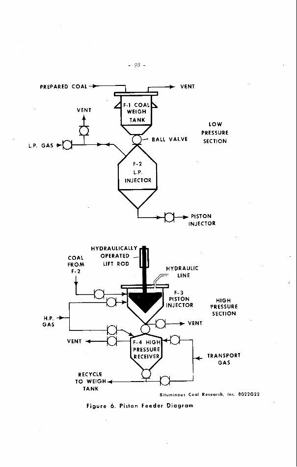
A s shown i n Figure 6, the piston coal feeder has two main operating sections, a low-pressure section and a high-pressure section.
storage tank t o t h e weigh tank, F-1, using an iner t gas as the transport medium. From the weigh tank, F-1, a t atmospheric pressure, the coal flows by gravity through a pneumatically operated b a l l valve in to a low pressure injector vessel, F-2. The injector vessel, F-2, i s pressurized with recycle product gas t o about 90 psi .
In the low pressure section, pulverized coal is transferred pneumatically from a f
I n the high pressure section, whi le the piston is i n t he raised posi- t i on , t h e coal-gas mixture i n the F-2 vessel i s vented in to the high pressure piston injector vessel, F-3. F-3 vessels i s then closed and the F-3 vessel i s pressurized t o about 100 lb above tha t of a high-pressure receiver, F-4. F-3 vessel and the F-4 vessel is then opened; by so doing, the coal plus gas i s allowed t o flow into the receiver vessel. Hydraulic pressure lowers the specially designed piston and completes the t ransfer of the residual coal-gas charge i n t o the high-pressure receiver. The valve between the two vessels i s closed, the small quantity o f high pressure gas remaining in the injector vessel i s vented t o a gas holder, and the piston i s re- turned t o i t s o r ig ina l posit ion by means of a hydraulically operated lift rod.
The b a l l valve between the F-2 and
The valve between the
The en t i r e cycle i s then repeated automatically.

- 17 -
In t e s t operations a t the BCR laboratories, performance data have
In these t e s t s , the unit was operated routinely, injecting been collected on the gas. consumption,, capacity, and r e l i a b i l i t y of the system. coal a t ra tes up t o 800 lb/hr into a receiving vessel pressurized t o 1,400 p s i .
For the 5 ton/hr p i l o t plant, it i s planned t o i n s t a l l two piston feeders, each with a capacity of 2.5 ton/hr. I n addition, the layout for the p i lo t plant w i l l provide for the in s t a l l a t ion of an al ternate lock- hopper system t o deliver coal t o the high-pressure coal feed tanks repre- sented as F-4 i n Figure 6. on the piston feeder i s required, operation of t he gasif icat ion plant can be sustained by means of the lock hopper-feed arrangement.
Thus, i n the event extended development work
Various designs of feeders fo r delivering the coal from the high- pressure receivers t o the transport l i nes t o the gas i f i e r a r e being studied. Tentatively, it i s planned t o use a specially designed screw feeder for t h i s application, but further development work and t e s t ing of feeders i s required t o es tabl ish the most suitable feeder f o r t h i s purpose. gas w i l l be used for t h e transport medium and, at pressures of about 100 atm, the weight r a t i o of coal t o gas w i l l be about 8:i .
Frocess
C . Coal Gas i f i ca t ion
As stated i n the general description of the p i l o t plant , t he gas i f i e r w i l l be an oxygen-blown, two-stage u n i t designed for coal feed r a t e s up t o 5 ton/hr and a maximum operating pressure of 1,500 ps i . adaptable t o a l l ranks of coals.
The u n i t w i l l be
The outside diameter of the gas i f i e r i s 5.5 f ee t , and the diameter inside the refractor ies i s 3 f ee t . 6 f ee t and 14 f ee t , respectively, and the height of t he slag quench and removal section i s 13 f ee t . changes i n feed rate and operating pressure. veloci t ies fo r Stages 1 and 2 a re 0.27 f t / s ec and 0.15 f't/sec, respectively; corresponding maximum residence times a re 24 and 73 seconds. maximum veloci t ies are 2.3 and 1.12 f t /sec for Stages 1 and 2, respectively, and the corresponding minimum residence times are 2.9 and 9.8 seconds. gas e x i t temperature w i l l be about 1700 F and, as shown in Table 1, the composition of t h e gas w i l l be approximately 16 percent carbon dioxide, 28 percent hydrogen, and 7 percent methane, with the balance being water and less than 1 percent each of nitrogen and hydrogen sulfide.
The heights of Stages 1 and 2 a re
Velocities i n each stage w i l l vary w i t h The expected minimum gas
The expected
The
A simplified process flow diagram with major flow ra t e s and operating conditions fo r a coal feed r a t e of 5 ton/hr i s shown i n Figure 7. material balance is given in Table 2.
A
Dry, pulverized coal, conveyed with steam, is fed into the upper stage (Stage 2) . The coal i s devolati l ized and p a r t i a l l y gasified in Stage 2 by the steam and the hot gases and char r i s ing f r o m the lower reaction zone (Stage 1).

m a d
I m
in 5
in
0 -?

'I
?
TABU 2. MATERIAL BALANCE FOR 5 TON/HR OXYGEN-BLOWN TWO-STAGE GASlFIER
Input Weight, lb/hr
Stage 2
coal 10,000
Transport Gas Recycle (1,9191
Steam 8,774 18 , 774
Stage 1
Char Recycle
Steam Feed Gas Recycle
Steam
oxygen ' (99.5%)
Total Input
output
Stege 2
Raw F'roduct Gas
Recycle Gas
Recycle Char
Stage 1
Slag
Total Output
(9,408)
( 275 1 2,880
6,361 9 , 241
28,015
684 684
28,015

- 20 -
The products leaving the gasif ier are f i r s t cooled; t h e 'entrained char i s then separated from'the gas, collected, and reinjected with oxygen and additional steam into the Stage 1 reaction zone.
Molten slag formed i n Stage 1 drops through a water spray into a reservoir of l iquid water below. are periodically removed through a lock hopper system. '
The result ing granulated s lag par t ic les
D. Waste Heat Recovery and Char Recycle System
Details of t he waste heat recovery and char recycle system are shown in Figure 8. and direct water sprays, the temperature of the char and gas w i l l be de- creased t o about 900 F. A multi-cyclone unit w i l l be used f o r separating the char from t he gas. By sequential operation of lock hoppers, the char i s dropped by gravi ty into the gasif ier char feed bin.
By means of a heat exchanger, essent ia l ly a waste heat boi ler ,
Similar t o t h e s i tuat ion with coal feeders, various types o f char Present plans for feeding hot char t o feeders are being investigated.
bin t o deliver char into a standpipe which i n turn w i l l feed a specially designed screw feeder. Maintaining a uniform head of char with uniform bulk density on the screw feeder f a c i l i t a t e s the problem of maintaining uniform feed rates . The gas i f i e r w i l l be equipped with three reactant or char burning nazzles. Each nozzle w i l l be equipped w i t h a separate feed system.
Stage 1 are t o use an arrangement of a rotary valve a t the base of the feed r
About 95 percent of t h e char w i l l be returned by the multi-cyclone. Approximately two-thirds of the char entering Stage 1 is gasified and about one-third is recycled. .Thus, about 1.6 lb of fixed carbon is recycled t o Stage 1 for each pound of fixed carbon entering w i t h the coal i n Stage 2.
The gas, w i t h f i ne ly dispersed char, passes from the multi-cyclone t o a second heat exchanger, steam generator, where the gas temperature is reduced t o 650 F i n preparation for the carbon monoxide shift reaction. After the heat exchanger, t he gas i s f i l t e r e d t o remove the f i n e char. Currently, a sand bed f i l t e r i s under investigation fo r the removal of f ine char. If successful, it will eliminate the need fo r further cooling of the gas and subsequent reheating for the CO s h i f t . If sol id bed f i l t e r s are unsatisfactory, it may be necessary t o r e so r t t o bag-type filters which presently require gas temperatures below 500 F, o r t o w e t scrubbing which w i l l lower t h e gas temperature even further. necessary t o reheat the gas pr ior t o t h e CO s h i f t .
I n e i ther case it would be
The char recycle system w i l l provide for e i ther returning the f ine char t o the gas i f i e r char feed bin or fo r removing ,it from the system.

- 21 -
E. Carbon Monoxide Shif t
The purpose of the carbon monoxide shift conversion i s t o adjust the hydrogen t o carbon monoxide r a t io in t h e gas t o 3.1 t o 1 as required for the methane synthesis. As shown i n t h e simplified process flow diagram, Figure 9, the f a c i l i t i e s w i l l include catalyst guard f i l t e r s , reactors, and the appropriate heat exchangers.
CO sh i f t f a c i l i t y a t a temperature of 650 F and a pressure of about lo00 ps i . genated; s u l f u r compounds such as carbonyl sulf ide wlU be converted t o hydrogen sulfide; and any fine char remaining i n the gas will be trapped.
providing two units, the catalyst i n the off-stream uni t may be regen- erated with steam and a i r .
Gas from the heat recovery and char removal system w i l l be fed to the
In the ca ta lys t guard f i l t e r s , any olef ins i n the gas w i l l be hydro-
Superheated steam w i l l be added t o the gas entering the reactors t o adjust the steam t o d r y gas r a t io t o 0.7. Composition of the feed gas t o the reactors i s shown in Table 1. The extent of reaction and thus the - hydrogen t o carbon monoxide r a t io of t he ex i t gas stream will be controlled by appropriate set t ings of the following operating conditions: steam/gas r a t i o , (2) the amount of gas bypassed, and (3) reactor inlet gas temperature.
w i l l be about 40 percent of t he feed gas and that 95 percent of the carbon monoxide i n the remaining 60 percent will be converted t o hydrogen and carbon dioxide.
(1) the
For t he 5 ton/hr p i lo t plant it i s expected that the bypass stream
The exothermic heat release Prom the reaction w i l l r a i s e the gas temperature fYom 650 F t o about 865 F. with the bypass stream, the gas is cooled t o 95 F. t he mixed gas stream, having a %/CO r a t i o of 3.1, i s shown i n Table 1.
After mixing the converted gas The composition of
F. Acid Gas Removal
From a study of some 35 available acid gas removal processes, it was concluded tha t the c r i t e r i a established for the BI-GAS process were best sa t i s f ied by those processes employing an organic solvent as t he stripping medium and which select ively remove t h e hydrogen sulf ide and carbon dioxide. Such processes include the Furisol, t h e Rectisol, and t he Selexol.
and sulf’ur recovery based on the Purisolprocess and a Claus u n i t for re- covery of elemental sulfur .
Figure 10 i s a simplified process flow diagram of the acid gas removal

- 22 -
The gas from the CO sh i f t converter w i l l f i r s t pass through an absorber where the hydrogen sulfide w i l l be absorbed i n N-methyl-2-pyrrolidone. hydrogen sulfide w i l l be steam stripped from t h e solvent i n a separate tower and fed t o the Claus sulfur recovery plant. cycled. a second absorber where the carbon dioxide is absorbed. The carbon dioxide w i l l be stripped from the solvent i n a separate vessel and vented t o atmos- phere; the solvent is recycled.
The
The solvent w i l l be re- The process gas from the hydrogen sulfide absorber w i l l pass through
To sa t i s fy pipeline gas specifications the hydrogen sulf ide content The composition of the of t he gas must be below 0.25 grain per 100 scf .
gas leaving the acid gas removal section is shown i n Table 1.
G. Methanation
The most advanced designs of methanation processes - t h a t is , the conversion of carbon monoxide and hydrogen t o methane, are based on fixed- bed catalyt ic reactors. However, i n fhe interest of furthering research i n t h i s area, current laboratory work i s directed toward development of a methanation system based on a fluidized-bed catalyt ic reactor.
A simplified process f l o w diagram of the methanation s t ep based on using a fluid-bed reactor i s shown i n Figure 11.
The methanation reaction is highly exothermic, and temperature control i s c r i t i c a l . Below 500 F the carbon monoxide reacts with the nickel cata- l y s t t o form nickel carbonyl, resul t ing i n loss of catalyst and the pro- duction of a hazardous gas. reaction of hydrogen with carbon t o form water and elemental carbon, result ing i n a decrease i n yield.
Above 500 F carbon formation occurs by the
I
The fluid-bed reactor should provide for be t t e r heat t ransfer than With suff ic ient cooling coi ls and i s possible with fixed-bed reactors.
heat exchange capacity, the exothermic heat should be controllable a t higher levels of carbon monoxide concentration i n the feed gas than i s now possible.
The temperature of the feed gas w i l l be i n the range of 550 t o 625 F. '
I n t h e p i lo t plant, provisions w i l l be made t o introduce the feed gas a t three levels t o permit dis t r ibut ion of heat. (See Figure ll.) With the appropriate arrangement of cooling co i l s and heat exchangers, it is expected t h a t process gas containing about 20 percent carbon monoxide can be fed d i r ec t ly t o the methanator.
Btu/scf, w i l l have a composition as shown i n Table 1. The f i n a l pipeline gas, having a gross ca lo r i f i c value of about 950

- 23 -
IV. GENERAL FACILITIES
The research f a c i l i t y now being planned, requiring approximately 25 acres, is t o be located near U. 8 . Highway 119 j u s t north of Homer City, Pennsylvania, not far from the BCR research center a t Monroeville, Pa. The f a c i l i t y would be l a i d out t o accommodate the proposed experimental systems plus general u t i l i t i e s . Space f o r expansion would also be provided, especially i n the gas processing area.
Water f o r cooling purposes, steam generation, and f i re protection will be supplied from Two Lick Creek which borders on t h e plant property. U t i l i - zation of t h i s water w i l l require in s t a l l a t ion of f a c i l i t i e s fo r pumping, cooling, f i l t e r ing , and chemical treatment. City water will be available for limited required uses.
I n a commercial plant, steam requirements may be sa t i s f i ed by use of heat exchange equipment in the gas treatment section of t he plant. ever, a steam boiler w i l l be provided fo r the p i l o t plant t o assure opera- t i on of the gasif ier exclusive of the gas treatment f a c i l i t i e s .
How-
Adequate e l ec t r i ca l power w i l l be furnished t o the plant so no genera- t i ng equipment i s required. The necessary substation and motor control
I rooms w i l l be installed.
Buildings w i l l be provided f o r office, laboratory, maintenance, and other services as required. parking l o t s , communication system, etc . all waste products collected t o eliminate environmental pollution.
Miscellaneous f a c i l i t i e s w i l l include roads, I A l l effluents w i l l be t r ea t ed and
\ v. SUMMARY
The design characterist ics of a fu l ly integrated coal-to-pipeline gas p i l o t plant based on the BI-GAS process have been delineated. A t t he pre- sent t i m e , these are being incorporated i n an engineering bid package scheduled fo r completion i n October, 1971. With appropriate funding, pro- curement and erection o f a 5 ton/hr p i l o t plant on the s i t e a t Homer City, Pennsylvania, may be reasonably expected t o be completed by early 1974.
1
ACKNOWLEDGMENT
This paper i s based on work performed a t Bituminous Coal Research, Inc., with support from the Office of Coal Research, U. S. Depaxtment of the Inter ior , under Contract No. 14-01-0001-324.

- 24 -
LrrERATuRE CITED
1. Glenn, R. A., Donath, E. E., and Grace, R. J., "Gasification of coal under conditions simulating Stage 2 of the BCR super-pressure gasifier," i n "Fuel Gasification," Washington: ACS, Advan. Chem. Ser. 69, 1967. pp 81-103.
2. Grace, R. J., Glenn, R. A,, and Zahradnik, R. L., "Gasification of l i gn i t e by t h e BCR two-stage super-pressure process,'' A I C h E , Symp. Synthetic Hydrocarbon Fuels from Western Coals, Denver, Colorado,
"Gas Generator Research and Developnent - Phase 11. Process and Equipment Development ,I1 Bituminous Coal Research, Inc . , Rept . t o U. S. Office Coal Res., Washington: U. S. Government Printing Office, 1971.
"Gas Generator Research and Development - Survey and Evaluation," Bituminous Coal Res. , Inc . , Rept . t o U. S. Office Coal Res., Washington: U. S. Government Printing Office, 1965. 650 pp. (Out of p r i n t copies on f i l e a t OCR repository l ibrar ies . )
Glenn, R. A., "A multipurpose research p i lo t plant f a c i l i t y featuring BCR two-stage super-pressure coal gasification," ACS Div. Fuel Chem., Chicago, Ill., September, 1970.
Glenn, R. A., "Status of the BCR two-stage super-pressure process," Am. Gas ASSOC., Third Synthetic Pipeline Gas Symposium, Chicago, Ill., 1970.
1970 m
(OCR Research and Development Report No. 20.)
3.
4.
5.

- 25 -
COAL +
GAS PURIFICATION
AND M E T H A N A T I O N
I + v
CYCLONE
ZONE 2
GASIFIER
RECYCLE so
+ O X Y G E N
DS
GAS
ZONE 1
Y v SLAG
Bituminous Coal Rereorch, Inc. 8022017
Figure 1. Simplif ied Flow D i a g r a m for Two-stage .S u per- press u r e 0 a s i f i er

SlORAGE 0 - 26 -
? I
I 4 ! I I
I GASIFIER ~ , FLUIDIZED BED I PISTON
r
I ' I I ___i__ i-- .I
COAL 2 I BENEFlClAllON I . L .J . F,
, HANDLING
I ?
SLAG
PIPELINE GAS
4 SULFUR
Figure 2. BCR/OCR 'El-GAS Pilot Plant Flow Diagram
PRIME GRADE WASHED COAL - _ _ _ _ - _ - - - - - ----- I FROM BENEFICIATION 1
TO CRUSHED COAL I &TRAMP IRON TRUCK HOPPER BELT WASHED COAL
l%"x 0
I I t I I
I
BY-PASS ; RUN OF MINE COAL --,---)I------ +, I O ' X 0 I
I I I
I ,--;sscF I
I PICKING ++- - - - - BY-PASS I
I I I
I I
FUTURE FACILITIES I CRUSHER 'LJ 1 SHOWN BY BROKEN L INES 1
I SAMPLER / r _____-____- - - - - - - J E Y- PA SS I
'0 b-, /// RECLAIMING \,g HOPPER
\ \
(CONICAL PILES) CRUSHING AND SCREENING STATION
Bituminous C o d Resscmh. In< 8022G19
Figure 3. Coal Handl ing a n d Storage System Flow Diagram
BINS

I
%” x 0 --+ REFUSE
.-
\
PRIME COAL
TABLES fi!.!?%LNGS. AIR FLOW
7 CYCLONE AND FILTER DUST I
FLOTATION UNIT
MIDDLINGS CENTRIFUGE
, MIDDLINGS 1 STORAGE
WASHED COAL v
TO CRUSHED COAL BINS
PRIM ORA
Bituminous Cool Rerearch. In<. 8022G20
F i g u r e 4. C o a l B e n e f i c i a t i o n F l o w D i a g r a m
SAMPLER PRIME GRADE WASHED COAL
FROM BENEFICIATION / 1 0 - - - - - - - - - - -
TO STORAGE OR FUTURE BENEFICIATION WEIGH FEEDERS
SECONDARY BLEED +-,-I . SEPARATOR
PULVERIZED COAL BIN \-
I &’(BAG FILTER)
PRIMARY SEPARATOR\ (CYCLONE)
CLASSIFIER /
f---
ROTARY, ROTARY VALVE -VALVE
SCREW CONVEYOR
AIR HEATER PULVERIZER FEEDER , AND DRYER WEIGH
ROTARY - VALVE PNEUMATIC CONVEYOR ,o COAL FEED BIN
i
Bituminous Coal Research. In<. 8 0 2 Z G 1 1
F i g u r e 5. Coal H a n d l i n g a n d P r e p a r a t i o n System Flow D i a g r a m
- 23 -
PREPARED COAL -+ VENT 1 r c I
LOW PRESSURE
H.P. GAS
1 - w PISTON INJECTOR
HYDRAULICALLY COAL OPERATED -
HIGH PRESSURE SECTION
TRANSPORT GAS
TANK Bi tuminous C o a l Research, Inc. 8 0 2 2 6 2 2
Figure 6. Piston Feeder Diagram

RAW GAS 9 9 0 PSlG TPH
\ /
I
I
COAL FEEDER LOSS 15 SCFM
0 . 2 2 TPH
I A 13.28 RECYCLE GAS 5OOF A 13.28 RECYCLE GAS
Ai 6 9 7 18
COAL FEEDER
LOSS 15 SCFM CONDENSATE 0 . 2 2 TPH TO DRAIN
0 . 3 5 TPH +-
A h CHAR FEED
l r RECYCLE GAS
8 3 S C F M
TRANSPORT GAS, 5 8 9 SCFM
GASIFIER COAL 5 TPH I TRANSPORT GAS, 5 8 9 SCFM
COAL 5 TPH - -
lOS0 PSlG
4 . 9 3 TPH 9 3 2 F
0 .85 S:Er: TPH 8 0 0 F Ig 1000 F - _.
OXYGEN A- 3.18 TPH 8 0 0 F
SLAG 2 8 0 0 F 0 . 3 TPH
r-
+ 6 9 7 18
CONDENSATE TO DRAIN 0 . 3 5 TPH
CHAR FEED RECYCLE
GAS 8 3 S C F M *- _.
8OOF STEAM 0 5 8 TPH
CHAR 4 7 TPH
- _ _
Bituminous Coal R e i a o r r h , In< 8022G23
Figure 7. Process Flow Diagram for 5 TPH O x y g e n - b l o w n Two-stage Gasif ier
~ SATURATED S T L . RAW GAS AND CHAR
AT 1700 F
GASIFIER
OUENCH 1: BFW
WATER 'I' \ ' ~ ' \ STEAM \ I STEAM GENERATOR ,+ -+
I 1 __ I I
GENERATOR
'J \ GAS FILTER --t- r7
/ '\i CHAR SEPARATOR
CLEAN GAS AT 6 5 0 F
TO CO-SHIFT
GASIFIER n ' CHAR FEED BIN
Bituminous Cool Reseorrh. In'. 8022624 CHAR FEEDERS -
Figure 8. Waste Heat Recovery a n d Char Recycle Flow D i a g r a m

GAS AT 650 F FROM CHAR AND HEAT
RECOVERY AREA I
CATALYST GUARD FILTERS
c o 2
GASTO C 0 2 ,
REMOVAL PLANT A
H2S ABSORBER
I.. -
StTURATED+ !
> ’ CONDENSATE
SWEET GAS GAS TO +METHANATION
UNIT
CONDENSATE
CO- SHI FT S T E A M HEAT REACTORS GENERATORS EXCHANGERS
Bi luminour Cool Resear<h. In<. 8 0 2 2 0 2 5
Figure 9. CO-shift Flow Diagram
r-- --1 ABSORBER
COOLER
I-- STEAM
GAS AT 9 5 F
RECOVERY PLANT
FURNACE COOLER
STRIPPER
ACTIVE CARBON
TOWERS
TO METHANATION
TRANSFER PUMPS
REACTOR
SULFUR TANK
Bituminous Cool Raiear<h. Inr. 8021026 TRANSFER PUMPS
Figure 10. Acid-gar Removal a n d Sulfur Recovery Flow Diagram

- 31 -
E

- 32 - THE SYNTHANE COAL-TO-GAS PROCESS: A PROGRESS REPORT
A. J . Fortrey and W . P . Haynes
Bureau o f M i n e s , U.S. Department of t h e I n t e r i o r , P i t t s b u r g h , Pa.
INTRODUCTION
N a t i o n a l e n e r g y n e e d s demand t h e deve lopmen t of a s u p p l e m e n t a l n a t u r a l gas from c o a l . T h i s i s o f d e e p c o n c e r n t o t h e p i p e l i n e i n d u s t r y , t h e g a s i n d u s t r y , and t h e c o a l i n d u s t r y . What i s needed i s an o p e r a b l e economic p r o c e s s . The Bureau o f Mines a t Bruce ton ; P a . , h a s d e v e l o p e d a p r o c e s s f o r making a h igh -Btu g a s f rom c o a l - - t h e S y n t h a n e P r o c e s s . The s t e p s o f g a s i f i c a t i o n , g a s p u r i f i c a t i o n , and m e t h a n a t i o n have been tes ted t o t h e p o i n t t h a t a p r o t o t y p e p l a n t i s b e i n g d e s i g n e d .
THE OVERALL PROCESS
The S y n t h a n e P r o c e s s is shown s c h e m a t i c a l l y i n f i g u r e 1. The maim components a r e t h e g a s i f i e r , t h e s h i f t c o n v e r t e r , t h e p u r i f i c a t i o n s y s t e m , a n d t h e c a t a l y t i c m e t h a n a t o r . The water-gas s h i f t s t e p i s commerc ia l , and no work h a s been done on t h i s s t e p . The Bureau h o t ca rbona , t e p u r i f i c a t i o n work was d e v e l o p e d a b o u t 10 y e a r s a g o 11 and h a s been a d o p t e d c o m m e r c i a l l y b u t i s no l o n g e r b e i n g r e s e a r c h e d . g a s i f i e r and m e t h a n a t o r a r e b e i n g t e s t e d a t t h e p r e s e n t t i m e .
. The p u r i f i e d gas h a s a h e a t i n g v a l u e of a b o u t 500 B t u / c u f L b e f o r e m e t h a n a t i o n and a h e a t i n g v a l u e e x c e e d i n g 900 B t u / c u f t a f t e r m e t h a n a t i o n .
The
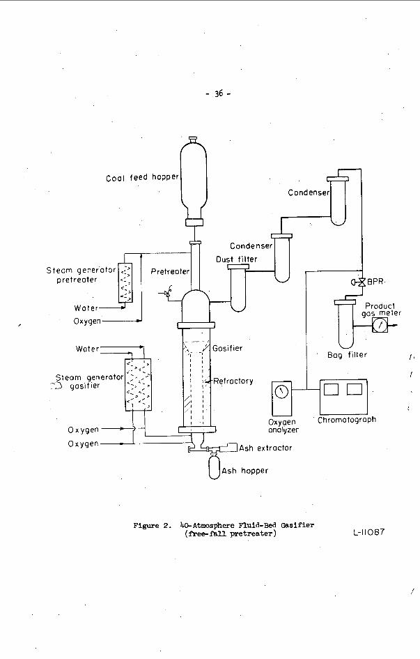
The G a s i f i e r
The g a s i f i e r i s shown i n f i g u r e 2 . I t i s a f l u i d - b e d t y p e , o p e r a t i n g a t 40 a t m o s p h e r e s (600 p s i a ) a n d up t o 1 ,000" C (1 ,830" F ) . The c o a l , 70X t h r o u g h .ZOO mesh , i s dropped t h r o u g h t h e p r e t r e a t e r w i t h oxygen and s t e a m ( o r CO;,) a t 400" C (750" F ) , where i t is r e n d e r e d n o n - c a k i n g . i n t o t h e c a r b o n i z a t i o n z o n e and f i n a l l y t'o t h e g a s i f i c a t i o n z o n e where i t is g a s i f i e d w i t h s t e a m p l u s oxygen .
The decake,d c o a l t h e n f a l l s
R e s u l t s o f t h e l a t e s t t es t s w i ~ h f r e e - f a l l p r e t r e a t m e n t a r e shown i n t a b l e 1 , where t h e d a t a a r e compared w i t h a s s u m p t i o n s made f o r t h e economic s t u d y . The d a t a shown have met or e x c e e d e d a l l assumpti .ons made, c o n s i d e r i n g t h e l i m i t a t i o n s o f o u r 6 - f o o t - h i g h g a s i f i e r w i t h r e s p e c t t o t h r o u g h p u t . A u n i q u e f e a t u r e o f t h e p r o c e s s i s t h a t a l m o s t 60% o f t h e , m e t h a n e i n t h e p r o d u c t g a s i s made i n t h e . g a s i f i e r .
The Me thana t o r
The deve lopmen t o f t h e m e t h a n a t i o n s t e p h a s p roceeded on two p r o c e s s e s : t h e h o t - g a s - r e c y c l e (HGR) 2/ and t h e t u b e - w a l l r e a c t o r (TWR). 21 Development
- I / J . H . F i e l d , e t a t . Removing Carbon D i o x i d e and Hydrogen S u l f i d e . BuMines B u l l . 5 9 7 , 44 pp. 1962.
- 2 / A . J . F o r n e y , R . J . Demsk i , D . B i e n s t o c k , and J . H . F i e l d . Recen t C a t a l y s t Deve lopmen t s i n t h e Ho t -Gas -Recyc le P r o c e s s . BuMines R . I . 6 6 0 9 , 32 p p . , 1965.
- 3 / w . P. H a y n e s . J . J . E l l i o t t . A . J . ,Youngblood, and A . J . F o r n e y . O p e r a t i o n o r a Sprayed Raney N i c k e l Tube Wall R e a c t o r f o r P r o d u c t i o n o f a H igh-Btu Gas. P r e p r i n t o f D i v i s i o n of F u e l s C h e m i s t r y o f ACS M e e t i n g , S e p t . 1970, C h i . , I l l .
P i l o t P l a n t S t u d i e s o f t h e Ho t -Carbona te P r o c e s s f o r

- 3 3 - . a t p r e s e n t is i n t h e TWR s y s t e m . T h i s s y s t e m is shown i n f i g u r e 3 . W i t h i n t h e meth- a n a t o r , t h e g a s ( f r e s h f e e d p l u s r e c y c l e ) p a s s e s up o v e r t h e o u t s i d e o f s e v e n 2 - i n c h d i a m e t e r t u b e s which a r e t h e r m a l s p r a y e d w i t h Raney n i c k e l t o a t h i c k n e s s o f 0.020 to 0.030 i n c h . The t u b e s a r e b a f f l e d t o i n c r e a s e t u r b u l e n c e o f t h e g a s f l o w . ' R e s u l t s o f t h e l a t e s t t e s t are shown i n f i g u r e 4 . The p r e s e n t t es t h a s b e e n o p e r a t - i n g 2900 h o u r s , e q u i v a l e n t t o 240,000 SCF o f h i g h - B t u g a s / l b o f c a t a l y s t . The d e s i r e d s u l f u r c o n t e n t b e f o r e m e t h a n a t i o n m u s t b e less t h a n 1 ppm; i n m e t h a n a t i o n tes ts a t B r u c e t o n t h e s u l f u r c o n t e n t o f t h e f e e d g a s h a s been as low as 10 ppb.
NEW DEVELOPMENTS
P r e t r e a t m e n t
The t h r o u g h p u t o f t h e g a s i f i e r would be improved i f a c o a l c o a r s e r t h a n 70% t h r o u g h 200 mesh c o u l d be g a s i f i e d . A t t e m p t s were made t o p r e t r e a t s u c h c o a l s , b u t n o t h i n g c o a r s e r t h a n 30% t h r o u g h 200 mesh c o u l d be p r e t r e a t e d i n t h e p r e s e n t f r e e - f a l l u n i t . The p r e t r e a t e r was changed b a c k t o t h e f l u i d - b e d s y s t e m used o r i g i n a l l y . 4,/ by 0 was p r e t r e a t e d e a s i l y w i t h less oxygen t h a n needed f o r t h e f r e e - f a l l s y s t e m .
F i g u r e 5 shows a s c h e m a t i c o f t h e new s y s t e m . C o a l 2 0 mesh
G a s i f i c a t i o n
The c h a n g e t o a c o a r s e r c o a l p e r m i t t e d a n i n c r e a s e i n t h e l i n e a r v e l o c i t y ; ' t h u s t h e c o a l f e e d c o u l d be r a i s e d e q u i v a l e n t to a b o u t 50 l b / h r - f t 3 .
A c h a n g e i n t h e bed h e i g h t o f t h e g a s i f i e r f rom 6 t o 1 2 f e e t is s c h e d u l e d , b i which would raise s i g n i f i c a n t l y t h e t h r o u g h p u t p e r g a s i f i e r i n t e r n a l cross-
s e c t i o n a l area.
M e t h a n a t i o n
Because t h e t u b e s were d i f f i c u l t t o c h a n g e i n t h e r e a c t o r shown i n f i g u r e 3 , where t h e R a n e l n i c k e l was s p r a y e d on t h e e x t e r i o r o f 2 - i n c h - d i a m e t e r t u b e s , t h e r e a c t o r was r e v i s e d . We s p r a y e d t h e c a t a l y s t o n t h e i n s i d e s u r f a c e o f 4 - i n c h - d i a m e t e r t u b e s . T h i s r e v i s e d u n i t is b e i n g t e s t e d . S i n c e t h e n we have s t a r t e d d e v e l o p m e n t o f a new method of s p r a y i n g t h e c a t a l y s t , w i t h t h e o b j e c t i v e o f c o a t - i n g t h e i n s i d e o f t u b e s as small as 1-5/8 i n c h i n d i a m e t e r and as l o n g as 30 f e e t . Such an improvement now a p p e a r s f e a s i b l e b e c a u s e w e found w e c o u l d u s e a wire s p r a y gun i n s t e a d o f t h e powder s p r a y g u n , which had many l i m i t a t i o n s .
I P r e s s u r e
E x t r a p o l a t i o n of r e s u l t s of t es t s a t 20 , 30, and 40 a t m o s p h e r e s show t h a t p r e s s u r e s of 70 a t m o s p h e r e s s h o u l d r e s u l t i n a y i e l d o f m e t h a n e e x c e e d i n g 5 s c f / l b c o a l f e e d . T h i s h i g h e r p r e s s u r e would r e d u c e t h e oxygen r e q u i r e m e n t by o n e - f o u r t h . The p r o t o t y p e p l a n t w i l l b e d e s i g n e d f o r 70 a t m o s p h e r e s t o v e r i f y t h i s c o n c l u s i o n .
t 41 A . J. F o r n e y , R . F . Kenny, S . J. Gasior, and J. H. F i e l d . F l u i d - B e d G a s i f i c a -
t i o n o f P r e t r e a t e d P i t t s b u r g h Seam C o a l . P r e p r i n t o f D i v i s i o n o f F u e l s Chem- i s t r y o f ACS, S e p t e m b e r 1 9 6 6 , N e w York , N .Y.
The P r o d u c t i o n of Non-Agglomera t ing C h a r From C o k i n g C o a l i n a C o n t i n u o u s F l u i d - B e d R e a c t o r . P r e p r i n t o f D i v i s i o n of F u e l C h e m i s t r y o f ACS, S e p t e m b e r 1964 , C h i c a g o , Ill .
- 5 / A . J. Forney , R . F . Kenny, S . J. Gasior, and J. H. F i e l d .
1

- 34 - CONCLUSION
The Syn thane P r o c e s s s t e p s o f g a s i f i c a t i o n , p u r i f i c a t i o n , and m e t h a n a t i o n have been proven a t t h e B r u c e t o n l a b o r a t o r i e s . Recen t improvements of t h e s e s t e p s have he lped t h e o v e r a l l p r o c e s s and s h o u l d make t h e p r o c e s s more a t t r a c t i v e e c o n o m i c a l l y . A l t h o u g h t h e d e s i g n o f t h e p r o t o t y p e p l a n t must b e f i x e d soon , con t i n u e d r e s e a r c h is e x p e c t e d t o improve t h e p r o c e s s .
TABLE 1. - L a t e s t tes t r e s u l t s o f t h e B r u c e t o n g a s i f i e r compared t o a s s u m p t i o n s made i n t h e
economic r e p o r t
Assumpt ions P l a n t t e s t
Throughpu t 25 l b / h r - f t 3
P r o d u c t Gas 16.2 SCF/lb 18.0 SCF/ lb MAF
CH4 4.45 SCF/ lb 4.95 SCF/ lb MAF
Test 196 199 197 204 32 30 43 36
18 .0 18.6 16.2 17.3 1 9 . 4 20.2 17 .5 19.0 I
4.40 4.65 4.16 4.51 4.74 5.04 4.48 4.97
cn4 27.5% 24.4 24.5 25.4 25.9
Carbon C o n v e r s i o n To Gas 66.8% 66.3 71.0 59.0 64.9
Steam Decompos i t ion 39% 38 3 2 32 37

- 35 -
\
/
- 36 -
S
,
Coal feed
earn pretreoter g e n e r o t o r 1
c- - < I - -7
Water i il hopper
Condenser ,-r Condenser T-r'
O x y g e n 2 H Woter-
'- -- '. c. :3 gasifier . I
I
Ash extractor
Ash hopper
0 x ygen
Oxygen
Oxygen onolyzer
1"'" Product
gas meter
Bog f i l ter
1". Chromatograph
Figure 2. bAtmosphere Fluid-Bed Gssifier (free-fall pretreater) L-11087

- 37 -
/
I
U

! i-

- 39 -
Cool feed hopper
UI Woter
Oxygen 1
Woter 1
gosi f ier . .
Oxygen - L
- _ _ )..... /,' Gosifier
/., .-5 , , ' Refroctory ,',I r <
",.? ' -1 '
'..I l,'
1 1 , ;q 1,;
r , 1 I ,
1 : . Oxygen onolyzer
Ash extroctor
U A s h hopper
gos meter
Bog filter
I" O1 C hrornotogroph
Figure 5 . bAtmosphere Fluid-Bed Gasifier (fluid-bed pretreater )

- 40 - BASIC FEATURES O F THE COa ACCEPTOR GASIFICATION PROCESS
D . R . Mosher. U. D. Marwig, and J . A . Phinney
Stearns-Roger C o r p o r a t i o n , P. 0. Box 1469, Rapid C i t y , SD 57701 Conso l ida t ion Coal Company, P . 0. Box 1687. Rapid C i t y , SD 57701 Conso l ida t ion Coal Company, Research D i v i s i o n , L i b r a r y , PA 15129
INTRODUCTION
The Rapid C i t y p l a n t embodies a unique chemica l , f l u i d i z e d bed system o r i g i n a l l y conceived by Conso l ida t ion Coal i n t h e 1940 ' s . The p l a n t i s l o c a t e d where t h e r e is easy access t o v a r i o u s s o u r c e s of l i g n i t e i n t h e huge W e s t e r n l i g n i t e f i e l d . The s c a l e of t h e p l a n t w a s chosen t o pe rmi t o b t a i n i n g p r e c i s e eng inee r ing d a t a and sca le -up information f o r commercial f a c i l i t i e s .
(except f o r i n s u l a t i o n and p a i n t i n g ) and p r e l i m i n a r y o p e r a t i o n s have s t a r t e d . A t t h i s p o i n t , t h e l a b o r a t o r y work is complete, p l a n t c o n s t r u c t i o n is complete
PROCESS DESCRIPTION
The product ion of p i p e l i n e g a s by g a s i f i c a t i o n of l i g n i t e u s i n g t h e Consol proeess h a s f o u r main s t e p s . The o v e r a l l s t e p s are shown i n F i g u r e 1. They a r e c o a l p r e p a r a t i o n , g a s i f i c a t i o n , gas p u r i f i c a t i o n , and methanation. Coal p re t r ea tmen t is a l s o shown; how- . e v e r , t h i s s t e p is unnecessary when l i g n i t e is g a s i f i e d . To handle sub-bituminous c o a l , i t i s ' n e c e s s a r y t o use a p re t r ea tmen t s t e p comparable to t h a t employed i n o t h e r g a s i f i c a - t i o n p r o c e s s e s .
Table I . The r e a c t i o n s of carbon, carbon o x i d e s , steam and hydrogen are t h e same i n a l l g a s i f i c a t i o n p r o c e s s e s . The r e a c t i o n s shown t h a t i n v o l v e ca lc ium qxide , calcium carbon- a t e , and carbon d i o x i d e are unique t o t h e Consol p r o c e s s . Through t h e s e r e a c t i o n s , h e a t i s t r a n s p o r t e d between t h e g a s i f i c a t i o n and combustion s e c t i o n s and s imul taneous ly carbon! d i o x i d e i s removed from t h e product g a s .
m i l l and s imul taneous ly d r i e d from a t o t a l mois ture c o n t e n t of 35% t o 5% u s i n g hot gas.
which a l so d r i v e s o f f some bound moisture and p o s s i b l y some C02. T h i s s t e p w i l l be modi- f i e d ' t o a pre t rea tment when sub-bituminous c o a l i s used .
L i g n i t e is a non-caking coal; and as a r e s u l t , t h e d r i e d and ground m a t e r i a l leaving1 t h e f l u i d i z e d bed h e a t e r i s ready f o r g a s i f i c a t i o n .
The g a s i f i c a t i o n s e c t i o n of t h e process ; a s i nco rpora t ed i n t h e p i l o t p l a n t , i s shown i n F igure 2. System. P r e s s u r e i n t h e hopper i s i n c r e a s e d t o g a s i f i c a t i o n p r e s s u r e o f 150 t o 300 P s i g . and t h e powder i s then f e d through a r o t a r y f e e d e r i n t o t h e f i r s t r e a c t i o n v e s s e l c a l l e d ' t h e d e v o l a t i l i z e r .
In t h e d e v o l a t i l i z e r , t h e l i g n i t e reacts w i t h a hydrogen-rich stream from t h e g a s i f i c a t 1500°F. The i n t r o d u c t i o n p o i n t of l i g n i t e i s a t t h e bottom of t h e bed and t h e v o l a t i l - m a t t e r from t h e l i g n i t e l e a v e s t h e t o p of t h e bed as methane, carbon monoxide, and hydrog:: The conf igu ra t ion of t h e vessel and o p e r a t i o n c o n d i t i o n s are such t h a t t h e r e i s e s s e n t i a l 1 no condensable hydrocarbon i n t h e product g a s .
t h e d e v o l a t i l i z e r . I t i s then l i f t e d i n t o t h e g a s i f i e r ( t h e v e s s e l on t h e r i g h t i n F i g u r e 2) us ing supe rhea ted steam as a motive gas.' In t h e p i l o t p l a n t , w e have t h e f l e x i b i l i t y of r e c y c l i n g gas t o t h e g a s i f i e r through a c leanup and compressor system. This i s a l so t r u e of g a s e s from t h e o t h e r r e a c t o r s . T h i s c a p a b i l i t y is included' i n t h e P i l o t P l a n t t o permi t s t u d y i n g a l t e r n a t i v e o p e r a t i n g schemes.
The key r e a c t i o n s t h a t t a k e p l a c e i n t h e COa Acceptor P rocess are summarized i n
I n t h e c o a l p r e p a r a t i o n s t e p , t h e l i g n i t e is crushed t o approximately 8 mesh i n a
AS a f i n a l s t e p i n p r e p a r a t i o n . , l i g n i t e is p rehea ted i n a f l u i d i z e d bed t o 572OF, 1 1
The crushed and d r i e d l i g n i t e powder i s in t roduced t o a lockhopper '
The d e v o l a t i l i z e d l i g n i t e (which w e can now r e f e r t o as char ) f l o w s by g r a v i t y from

- 41'- Carbon i n t h e c h a r i s g a s i f i e d by r e a c t i o n w i t h s team i n t h e g a s i f i e r . Res idua l
c h a r , c o n t a i n i n g about 35% of t h e o r i g i n a l ca rbon i n t h e l i g n i t e , f lows out of t h e g a s i f i e r by g r a v i t y and i s l i f t e d pneumat i ca l ly t o t h e r e g e n e r a t o r u s i n g a very smal l stream of g a s r e c y c l e d from t h e r e g e n e c a t o r as t h e motive g a s .
In t h e r e g e n e r a t o r , t h e r e s i d u a l carbon is burned a t approximately 1900'F t o supply t h e h e a t needed f o r t h e r e v e r s a l of t h e c a r b o n a t i o n r e a c t i o n s t h a t t a k e p lace i n t h e d e v o l a t i l i z e r and g a s i f i e r v e s s e l s ( s e e Tab le I ) . The r e s i d u a l a s h , c o n t a i n i n g about 5 a b s o l u t e p e r c e n t of t h e o r i g i n a l l i g n i t e ca rbon c o n t e n t , is e n t r a i n e d i n t h e o u t l e t g a s from t h e g a s i f i e r . T h i s r e s i d u e , t o g e t h e r w i t h f i n e s from t h e do lomi te c y c l e which w i l l be d e s c r i b e d n e x t , is removed from t h e r e g e n e r a t o r o f f g a s i n a cyc lone .
, In t h e p i l o t p l a n t a t Rapid C i t y , t h e s e s o l i d s w i l l be lockhoppered o u t of t h e system i n t o a tank where t h e y w i l l be s l u r r i e d w i t h water and pumped t o a s e t t l i n g pond.
g a s i f i c a t i o n and d e v o l a t i l i z a t i o n as WES mentioned ear l ier . This is t h e key t o t h e c02 Acceptor P r o c e s s . d e s c r i b e d l a t e r . I n t h e r e g e n e r a t o r v e s s e l , ca l c ium c a r b o n a t e is c a l c i n e d t o calcium oxide adso rb ing h e a t , and t h i s h e a t i s r e l e a s e d when t h e ca l c ium oxide i s conver ted back t o calcium carbonate by r e a c t i o n w i t h C02 i n t h e o t h e r r e a c t o r s .
e n t e r s t h e bottom and i s e l u t r i a t e d o u t t h e t o p a f t e r combustion w i t h air . Calcined dolomite from t h e r e g e n e r a t o r flows i n t o t h e o t h e r two v e s s e l s by g r a v i t y .
Dolomite i s in t roduced a t t h e t o p and comes out of t h e c h a r bed from a second f l u i d i z e d bed i n t h e small s e c t i o n a t t h e bottom of each v e s s e l . The small s e c t i o n s are c a l l e d boots . There i s l i t t l e c h a r i n t h e do lomi te boot s e c t i o n .
back i n t o t h e r e g e n e r a t o r . A i r w i l l be used as t h e motive f l u i d i n commercial p l a n t s . The p i l o t p l a n t i s a l s o equipped t o use r e c y c l e d g a s from t h e o u t l e t of t h e r e g e n e r a t o r .
The dolomi te cycle carries h e a t from t h e combustion i n t h e r e g e n e r a t o r t o t h e
Thermodynamic c o n s i d e r a t i o n s a s s o c i a t e d w i t h t h i s cycle w i l l be
The r e g e n e r a t o r r u n s e s s e n t i a l l y f u l l of f l u i d i z e d dolomi te . Char from t h e g a s i f i e r
i In t h e g a s i f i e r and t h e d e v o l a t i l i e e r , t h e t o p bed i s e s s e n t i a l l y a l l f l u i d i z e d char .
Dolomite from t h e s e b o o t s flows by g r a v i t y t o an engage r pot from where it i s l i f t e d
The product g a s f i n i s h i n g and methanat ion s t e p s a r e not inc luded i n t h e Rapid C i t y d P i l o t P l a n t . The techniques w i l l be s i m i l a r t o t h o s e used f o r o t h e r g a s i f i c a t i o n , p r o c e s s e s .
STATUS
A t t h i s p o i n t , bench-scale r e s e a r c h on t h e COz Acceptor P r o c e s s is f i n i s h e d and t h e p i l o t p l a n t i s complete e x c e p t for i n s u l a t i o n and p a i n t i n g . Some components of t h e p l a n t , m o s t l y s t a n d a r d d e s i g n s , have been t e s t e d . T r a i n i n g of o p e r a t i n g personnel w i l l be completed by mid-October, a t which p o i n t d r y r u n s w i l l b e g i n . These r u n s w i l l test 1 t h e g a s i f i c a t i o n c o n t r o l s , t h e s p e c i a l mechanical f e a t u r e s , and t h e f l u o - s o l i d t r a n s f e r
, between t h e r e a c t o r beds . These tests r e p r e s e n t a s tar t a t complet ing t h e f u t u r e develop-
W e e x p e c t t o begin g a s i f i c a t i o n s t a r t i n g i n February , and a t t h a t t ime, w e w i l l
P r e s e n t l y t h e p l a n s f o r t h e p i l o t p l a n t i n v o l v e t e s t i n g t h e least s e v e r e p r o c e s s
ments numbered "1" and "2" i n Table 11.
beg in a c q u i r i n g knowhow f o r commercial o p e r a t i o n (Item 3 i n Table 1 1 ) .
I concepts f i r s t and g r a d u a l l y working toward more d i f f i c u l t combina t ions . Each t e s t w i l l b r i n g u s c l o s e r t o a c h i e v i n g t h e t h r e e f u t u r e developments i n Tab le 11.
GENERAL REMARKS REGARDING OPERABILITY PROBLEMS I N GASIFICATION PROCESSES
The p r i c e for s y n t h e t i c g a s from c o a l is h i g h l y i n f l u e n c e d by c h a r g e s r e l a t e d t o t h e inves tment of t h e p l a n t . T h i s c a p i t a l i n t e n s i t y i s dependent on t h e n a t u r e of t h e f e e d s t o c k .

A s compared to pe t ro leum or t h e u s u a l pe t rochemica l raw materials, c o a l h a s p r o p e r t i e s
1. Coal is a s o l i d w i t h vary ing and only p a r t i a l l y p r e d i c t a b l e t h e r m o p l a s t i c
2 . I t c o n t a i n s minera l matter of vary ing composi t ion . 3 . I t has vary ing chemical and pe t rog raph ic c.ompositions, and an undefined
4 . I t i s t h e r m a l l y u n s t a b l e and decomposes t o y i e l d a wide spectrum of gases, o i l s ,
In a d d i t i o n t o t h e problems c r e a t e d by t h e s e unique raw material p r o p e r t i e s , t h e r e I s t h e b a s i c n e c e s s i t y of supp ly ing t h e l a r g e q u a n t i t i e s of h e a t r e q u i r e d f o r t h e endothermic g a s i f i c a t i o n r e a c t i o n a t t h e h igh tempera ture l e v e l s needed f o r a c c e p t a b l e r e a c t i o n k i n e t i c s .
which uniquely i n f l u e n c e a p rocess ing p l a n t inves tment . Some of t h e s e p r o p e r t i e s ' a r e :
p r o p e r t i e s .
complex chemical s t r u c t u r e .
and s o l i d s , t h e p r o p e r t i e s of which a r e i n f l u e n c e d by t h e c o n d i t i o n s of p y r o l y s i s .
Thus , t h e fo l lowing p o t e n t i a l o p e r a t i o n a l problems are common t o a l l c o a l g a s i f i c a t i o n processes :
1 . Feeding. 2 . Caking. 3 . Handling of v o l a t i l e matter. 4 . Supply of p rocess h e a t . 5 . Deposit f o r m a t i o n . 6. Ash removal. I n t h e e v a l u a t i o n of chemical p r o c e s s e s , t h e judgment u s u a l l y cu lmina tes i n a'
comparison o f t h e p r o j e c t e d p r o c e s s economics. When t h i s i s done f o r commercially proven p r o c e s s e s , t h e o p e r a b i l i t y i s a l r e a d y e s t a b l i s h e d and t h e r e s u l t of such an e v a l u a t i o n is r e l i a b l e .
of a l t e r n a t i v e p rocesses u s i n g c o s t estimates is a r a t h e r r i s k y v e n t u r e , e s p e c i a l l y i n t h e f i e l d of c o a l g a s i f i c a t i o n .
While t h e i n d i v i d u a l concept may f e a t u r e a d i f f e r e n t degree of d i f f i c u l t y i n each of t h e problem p o i n t s l i s t e d above, i t i s obvious t h a t p r o c e s s e s w i t h t h e most s t r a i g h t - forward s o l u t i o n t o t h e s e problems have t h e b e s t chance t o become commercialized. In judg ing concepts , one s h o u l d , t h e r e f o r e , examine t h e chances f o r o p e r a b i l i t y f i r s t of a l l . Many concepts based on sound chemis t ry have f a i l e d because some of t h e problems have t u r n e d o u t t o be insurmountable .
The C02 Acceptor P r o c e s s w i l l be examined i n t h e fo l lowing paragraphs i n each of t h e areas t h a t c r e a t e o p e r a t i o n a l problems.
Fo r conceptual p r o c e s s e s , however. w i t h on ly bench-scale r e s u l t s a v a i l a b l e , judgment
FEEDING PROBLEMS
A problem e x i s t s whenever a l a r g e q u a n t i t y of s o l i d s h a s t o be in t roduced a t a cont inuous and c o n t r o l l e d r a t e i n t o a p r e s s u r i z e d high tempera ture r e a c t o r . The t h r e e P r i n c i p a l means f o r accompl ish ing t h i s s t e p are a lockhopper s y s t e m , pumping c o a l as a s l u r r y , o r a p i s t o n f e e d i n g d e v i c e .
re a sons: The lockhopper system was chosen f o r t h e C02 Acceptor Process f o r t h e fo l lowing
1. O p e r a b i l i t y commercially e s t a b l i s h e d . 2 . Low investment and o p e r a t i n g c o s t f o r t h e p r e s s u r e l e v e l d e s i r e d . 3. Carbon d i o x i d e c a n be used f o r p r e s s u r i z i n g . 4 . Amenable t o au tomat ion . I n t h e p i l o t p l a n t , the sys tem c o n s i s t s of two hoppers , each wi th a c a p a c i t y Of one
hour o p e r a t i o n a t 1 . 5 t o n s ( F i g u r e 3 ) . The hoppers a r e opera ted a l t e r n a t e l y . While one Of them is connected w i t h t h e system and f e e d i n g , t h e o t h e r one is blocked of f whi le it i s d e p r e s s u r i z e d , f i l l e d w i t h c o a l , and f i n a l l y r e p r e s s u r i z e d w i t h C @ .

- 43 -
' p r e s s u r e . I t i s s i z e d f o r e i g h t h o u r s r e t e n t i o n t i m e of t h e c o a l i n o r d e r t o s e r v e a s a surge between t h e d r y i n g s y s t e m and t h e g a s i f i c a t i o n s e c t i o n .
The s y s t e m c o n s i s t s mainly of a n a t u r a l g a s - f i r e d f u r n a c e , a f l u i d i z e d bed v e s s e l , nd a v e n t u r i s c r u b b e r . In o p e r a t i o n as a n o x i d i z e r , t h e f u r n a c e i s f i r e d w i t h excess
a i r . A s tempering g a s , w e have t h e o p t i o n t o use e i t h e r steam o r f l u e g a s from t h e r e g e n e r a t o r of t h e g a s i f i c a t i o n section. The o u t l e t gas is quenched and scrubbed i n t h e v e n t u r i s c r u b b e r and r e l e a s e d t o t h e a tmosphere .
Because of t h e e i g h t hour r e t e n t i o n t i m e , mild o x i d i z i n g c o n d i t i o n s a r e s u f f i c i e n t . t i s in tended t o o p e r a t e a t 500 t o 600'F and up t o 6% 02 i n t h e i n l e t g a s wi th sub- i tuminous c o a l s .
In a commercial p l a n t , t h i s s y s t e m would be modif ied f o r o p e r a t i o n a t a s h o r t e r 6 e t e n t i o n t i m e , and consequent ly , s t r o n g e r o x i d i z i n g c o n d i t i o n s .
HANDLING OF VOLATILE MATTER
Each c o a l evolves v o l a t i l e matter d u r i n g thermal t r e a t m e n t . The amount and t h e omposi t ion of t h e s e v o l a t i l e s a r e determined by t h e rank of t h e c o a l as well as by he c o n d i t i o n s of t h i s t r e a t m e n t . I n a d d i t i o n t o f i x e d g a s e s , hydrocarbons ranging from eavy t a r t o l i g h t d i s t i l l a t e s of a l i p h a t i c or aromat ic n a t u r e a r e u s u a l l y p r e s e n t a s
Opera t ion i s semi-automatic by e l e c t r i c a l l y o p e r a t e d v a l v e s and push b u t t o n s . The f e e d r a t e is c o n t r o l l e d from t h e main c o n t r o l room by v a r i a b l e speed rotary f e e d e r s , and t h e amount i s measured by a system o f N l o a d c e l l s and t r a n s m i t t e r s .
The lockhoppers a r e c o n t i n u o u s l y purged w i t h a s m a l l f low of C02 t o keep h o t process g a s out d u r i n g t h e f e e d i n g p e r i o d and t o prevent a i r from e n t e r i n g d u r i n g t h e f i l l i n g o p e r a t i o n . T o t a l CO2 r e q u i r e d f o r p r e s s u r i z i n g and purg ing , 1300 SCFH, i s small compared to o t h e r p r o c e s s e s . The reason f o r t h i s is t h a t t h e lockhopper s a r e o p e r a t e d w i t h 500 t o 600'F p rehea ted c o a l which t e n d s t o d e c r e a s e p r e s s u r i z i n g and purge g a s r e q u i r e m e n t s .

- 4 4 -
The d e v o l a t i l i z e r reactor w a s designed f o r t h e s e c o n d i t i o n s . Fresh coal is fed i n t o t h e bottom of t h e f l u i d i z e d bed, and t h e bed h e i g h t provides s u f f i c i e n t r e t e n t i o n t i m e f o r t h e ascending v a p o r s t o react wi th steam and hydrogen p r e s e n t i n f l u i d i z i n g g a s .
'As a r e s u l t , o u r g a s c lean-up system is r a t h e r s imple (F igure 5 ) . I t c o n s i s t s of a quench tower wi th d i s c and doughnut i n t e r n a l s , a quench s e p a r a t o r , and a v e n t u r i sc rubber .
The quench water is r e c y c l e d t o t h e tower from t h e s e p a r a t o r and i n d i r e c t 1 y . c o o l e d . Excess water from c o n d e n s a t i o n o f undecomposed steam carries t h e p r e c i p i t a t e d s o l i d s out of t h e s y s t e m . We have provided a b a f f l e i n t h e quench s e p a r a t o r t o handle l i g h t o i l which might occur a t u p s e t c o n d i t i o n s o r s t a r t u p . I n t h e v e n t u r i sc rubber , t r a c e s of d u s t are removed from t h e g a s b e f o r e i t e n t e r s t h e r e c y c l e compressor.
i n s t a l l equipment f o r methanat ion and a s s o c i a t e d p r e p a r a t o r y t r e a t m e n t . A s mentioned b e f o r e , o u r g a s t r e a t m e n t is l i m i t e d t o t h e s e s t e p s because we d i d not
SUPPLY OF PROCESS HEAT
The method of h e a t supply h a s a g r e a t impact on t h e economy of a g a s i f i c a t i o n p r o c e s s . 'Problems are u s u a l l y a s s o c i a t e d wi th t h e requirement t o supply t h e h e a t a t r e l a t i v e l y h igh tempera ture l e v e l s t o t h e r e a c t i o n zone.
g a s , c o a l g a s i f i c a t i o n p r o c e s s e s can be c a t e g o r i z e d i n terms of t h e methods of supplying h e a t t o t h e g a s i f i c a t i o n zone; i . e . ,
1. Oxygen-blown sys tems. 2. C y c l i c p r o c e s s e s . 3. I n d i r e c t l y h e a t e d p r o c e s s e s ( e l e c t r i c a l h e a t , n u c l e a r energy , e t c . ) . 4 . Heat c a r r i e r p r o c e s s e s . The C02 Acceptor P r o c e s s f a l l s i n t h e las t c a t e g o r y .
I f c o n s i d e r a t i o n is l i m i t e d t o systems producing e s s e n t i a l l y n i t r o g e n - f r e e water
However, i t is di ' s t inguished from o t h e r s o l i d s r e c i r c u l a t i o n p r o c e s s e s by t h e f a c t t h a t most of t h e hea t is l i b e r a t e d by chemical r e a c t i o n .
A s descr ibed b e f o r e , c a l c i n e d dolomi te a t 1950'F is introduced t o t h e t o p of t h e reactor beds i n g r a n u l a r form. Because of t h e i r h i g h e r g r a v i t y , t h e p a r t i c l e s shower through t h e beds. On t h e i r way down, they react w i t h C02 which i s always p r e s e n t i n d e v o l a t i l i z a t i o n and g a s i f i c a t i o n zones .
A t t h e bottom of each reactor, t h e carbonated dolomite i s c o l l e c t e d i n a - b e d of smaller d iameter and a h i g h e r f l u i d i z i n g v e l o c i t y . From t h e s e small beds it is t rans- f e r r e d t o t h e r e g e n e r a t o r for c a l c i n a t i o n at 1950'F ( s e e F igure 2 ) . This r e a c t i o n r e q u i r e s h e a t which is s u p p l i e d by combustion of r e s i d u a l c h a r from t h e g a s i f i e r . A f t e r t h i s t r e a t m e n t , t h e dolomite i s ready f o r a n o t h e r c y c l e .
r e c a r b o n a t i o n u n t i l i t is r e p l a c e d by dolomite makeup. i s necessary t o maintain a r e a s o n a b l e a c t i v i t y l e v e l i n t h e c i r c u l a t i n g inventory'. W e expec t t h a t under t h e s e c o n d i t i o n s between 30 and 40 mol p e r c e n t of t h e c i r c u l a t i n g , dolomi te w i l l p a r t i c i p a t e i n t h e r e c a r b o n a t i o n r e a c t i o n .
1s s e n s i b l e h e a t and t h a t the major p o r t i o n of 72.5% i s h e a t of r e a c t i o n . is for one m o l of do lomi te a t 40% a c t i v i t y and 1950/1500°F tempera ture d i f f e r e n t i a l . The t o t a l h e a t s u p p l i e d t o t h e p r o c e s s by one m o l of dolomite under t h e s e condi t ions is about 40,000 BTU.
tempera ture d i f f e r e n t i a l f o r t h e same h e a t supply i f a l l t h e h e a t w e r e suppl ied by sen- s i b l e h e a t . A l l s o l i d s which have been used i n t h i s s e r v i c e as h e a t carriers such as sand o r char , e t c . , have roughly t h e same s p e c i f i c h e a t as dolomite . In t h e C02 Acceptor P r o c e s s , t h e weight r a t io o f c i r c u l a t e d dolomite t o c o a l f e d is between 3 and 4; whereas o t h e r g a s i f i c a t i o n p r o c e s s e s w i t h chemica l ly i n e r t h e a t carriers have t o c i r c u l a t e a burden Of 10 t o 15 t i m e s t h e i r coal f e e d . more inves tment , t h e a c c e p t o r p r o c e s s should be more economical than o t h e r processes of t h e h e a t carrier ca tegory .
j
1 ! The average a c c e p t o r p a r t i c l e w i l l undergo about 50 c y c l e s of c a l c i n i n g and
This replacement r a t e of 2%
F i g u r e 6 , a T-H diagram, shows t h a t on ly 27.5% of t h e h e a t c a r r i e d wi th t h e dolomite This diagram '
i About t h r e e and one-half times as much dolomite would be requi red a t t h e same
Since i n c r e a s e d s o l i d s f low i n a process means
1

- 45 - DEPOSIT FORMATION
Deposi t format ion is a problem common t o a l l g a s i f i c a t i o n p r o c e s s e s . Cons ide rab le time was s p e n t i n s t u d y i n g t h i s proble*m in t h e C02 Acceptor bench-scale s t u d i e s . It w a s found t h a t d e p o s i t s can o c c u r i n a l l t h r e e r e a c t o r s . The mechanism o f fo rma t ion is d i f - f e r e n t i n each p r o c e s s v e s s e l .
D e v o l a t i l i z e r d e p o s i t s are formed by i n t e r a c t i o n between sodium s u l f a t e , p y r i t e and s i o 2 , whi le i n t h e g a s i f i e r o n l y t h e las t two components are involved . There are no obvious means of p r e v e n t i n g t h e s e d e p o s i t s . The bench- sca l e d a t a i n d i c a t e s , however, t h a t w i t h most Western c o a l s , commercial o p e r a t i n g p e r i o d s of a t l e a s t s i x months can be achieved wi thou t d e s c a l i n g t h e r e a c t o r s . Obviously, however, c o a l s hav ing h i g h sodium s u l f a t e and p y r i t e s c o n t e n t s should be avoided. I n p a s s i n g , it shou ld be noted t h a t t h e d e v o l a t i l i z e r and g a s i f i e r d e p o s i t s are not r e l a t e d t o t h e p re sence of t h e dolomi te a c c e p t o r ; a l l g a s i f i c a t i o n p r o c e s s e s u t i l i z i n g Western c o a l s w i l l e n c o u n t e r t h i s problem.
In c o n t r a s t , t h e d e p o s i t s found i n t h e r e g e n e r a t o r are unique t o t h e C% Acceptor Process and can be much more s e v e r e . It was found t h a t t h e fo rma t ion mechanism is based on s u l f u r r e a c t i o n s i n r e g e n e r a t i o n and t h a t t h e d e p o s i t i o n can b e p r e v e n t e d by c o n t r o l l i n g the c o n d i t i o n s i n t h e r e g e n e r a t o r .
Calc ined dolomi te is a s good an a c c e p t o r f o r s u l f u r compounds a s f o r C02. The s u l f u r forms C a s , mainly i n t h e d e v o l a t i l i z e r but also i n t h e g a s i f i e r . In t h e r e g e n e r a t o r t h e CaS c o n t e n t of t h e a c c e p t o r i s o x i d i z e d i n t h e Cas04 by e i t h e r of t h e f o l l o w i n g r e a c t i o n s :
1/4 Cas + C02 ____) 1 / 4 Cas04 + CO o r 1 / 4 Cas + 1/2 02 ___) 1 / 4 CaSOq
When C a s and Cas04 e x i s t t o g e t h e r i n t h e absence of ca rbon o x i d e s , s u l f u r i s r e j e c t e d and t h e ca l c ium is conver ted t o CaO by t h e r e a c t i o n :
3 /4 Cas04 + 1/4 Cas - CaO i SO2
t h e r e a c t i o n , at t e m p e r a t u r e s above 1750°F, a t r a n s i e n t l i q u i d phase occurs which c o l l e c t s and s o l i d i f i e s on t h e r e g e n e r a t o r walls.
monoxide i n t h e r e g e n e r a t o r would p r e v e n t t h e d i f f u s i o n of t h e t r a n s i e n t l i q u i d t o t h e s u r f a c e of t h e a c c e p t o r p a r t i c l e s and thereby avoid its d e p o s i t i o n on t h e walls of t h e v e s s e l . The amount of CO r e q u i r e d depends p r i m a r i l y on t h e t o t a l amount of s u l f u r f e d t o t h e r e g e n e r a t o r and must be determined i n d i v i d u a l l y f o r each c o a l o r set o f o p e r a t i n g c o n d i t i o n s .
There is a p r i c e t a g a s s o c i a t e d w i t h t h i s s o l u t i o n ; namely, t h e r e j e c t i o n of carbon i n t h e r e g e n e r a t o r , which means l o s s i n o v e r a l l e f f i c i e n c y . Approximately 5% of t h e o r i g i n a l ca rbon of t h e coal must be s a c r i f i c e d .
T h i s l a s t r e a c t i o n i s t h e sum of v a r i o u s intermediate s t e p s . As a n i n t e r m e d i a t e i n
In s t u d y i n g t h e problem, i t w a s found t h a t a s l i g h t p a r t i a l p r e s s u r e o f carbon
ASH REMOV+
T h i s problem g e n e r a l l y i n v o l v e s t h r e e s t e p s : 1. S e p a r a t i o n of ash from t h e p r o c e s s . 2 . Removal from t h e p r e s s u r e system. 3. D i s p o s a l . S e p a r a t i o n of ash from t h e p r o c e s s takes p l a c e i n t h e r e g e n e r a t o r . The p a r t i c l e s ,
w h i l e r e a c t i n g w i t h a i r , move upwards through t h e i n t e r s t i c e s of t h e dolomi te bed. The ash p a r t i c l e s are s t r i p p e d out of t h e bed because t h e y are much f i n e r t h a n dolomi te p a r t i c l e s .
removed i n a w e t s c r u b b e r . Before e n t e r i n g t h e c y c l o n e , t h e gas(so1id mix tu re i s cooled from 1900 t o 1000°F by means of a wa te r - j acke ted p i p e .
S e p a r a t i o n of e n t r a i n e d a s h from t h e g a s t a k e s p l a c e i n a cyc lone and t h e rest is

- 46 - The removal from the p r e s s u r e system i s accomplished by a l t e r n a t e l y operat in 'g lock-
The r e s i d u e from t h e lockhoppers c o n t a i n s about 80% of t h e s u l f u r c o n t e n t o f t h e hoppers of a c o n f i g u r a t i o n s i m i l a r t o t h o s e descr ibed f o r c o a l f e e d i n g .
f e e d c o a l . Because i t is p r e s e n t as Cas, t h i s m a t e r i a l cannot be disposed of by dumping Rain would g r a d u a l l y l iberate H2S caus ing a bad odor i n t h e v i c i n i t y of t h e dump a r e a .
s l u r r i e d with water. The s l u r r y iS r e a c t e d wi th CO2 to release H2S whicli is incinerat .ed The innocuous s o l i d r e s i d u e i s t h e n pumped i n t o a s e t t l i n g pond.
Disposal i n a commercial p l a n t would be accomplished i n .a similar manner, except t h a t t h e l i b e r a t e d HZS would be conver ted t o s u l f u r . I n v e s t i g a t i o n s a r e under way t o f i n d commercial u s e f o r t h e r e s i d u e .
I n t h e p i l o t p l a n t , t h e a s h lockhoppers are d ischarged i n t o an a g i t a t e d tank and
CONCLUSION AND SUMMARY
The c o n s t r u c t i o n of t h e Rapid C i t y P i l o t P l a n t i s almost completed. After i n i t i a l
The p r o c e s s w a s examined w i t h r e s p e c t t o t h e s i x main problems commonly a s s o c i a t e d
For t h e problems of f e e d i n g , cak ing , and a s h removal, t h e p r o c e s s c o n f i g u r a t i o n
c o l d r u n s , g a s i f i c a t i o n t e s t s w i l l be s t a r t e d i n February of next y e a r .
w i t h c o a l g a s i f i c a t i o n .
o f f e r s t h e p o s s i b i l i t y of s t r a i g h t f o r w a r d s o l u t i o n s . w h i l e t h e problem with condensable hydrocarbons c a n be e l i m i n a t e d completely by a p p r o p r i a t e process s t e p s .
The p r o c e s s embodies a unique s o l u t i o n t o t h e h e a t supply problem wherein t h e h e a t i s t r a n s p o r t e d c h e m i c a l l y . The r e q u i r e d s o l i d s c i r c u l a t i o n r a t e i s only a f r a c t i o n of t h a t which would be r e q u i r e d i f a l l t h e h e a t were s u p p l i e d a s s e n s i b l e heat.
Western c o a l s i n a l l g a s i f i c a t i o n p r o c e s s e s . Bench-scale d a t a i n d i c a t e t h a t . w i t h most Western c o a l s , commercial o p e r a t i n g p e r i o d s of at. least s i x months can be achieved wi thou t s c a l e removal.
The problem w a s e l i m i n a t e d i n bench-scale tests a t t h e expense of a loss i n process '
e f f i c i e n c y .
The formation of a s h d e p o s i t s i n t h e d e v o l a t i l i z e r and g a s i f i e r i s expected w i t h
Deposit fo rma t ion i n t h e a c c e p t o r r egene ra to r i s a p o t e n t i a l l y s e r i o u s problem. f

W
- 47 -
Y
N X
+ 0 U
r h
v M
0 z
N
+ V
0 0 r.
r. 4
N z + 0 U
N
r M
0 X
+ 0 U
v
N
0 0 cv \D P-
..
m 0 V
U
t N 0 V
+ 0 a V
0 0 N
0 0 m .. .j N
2 t
r - h
U
M
O.4 X
+ N z rn
0' + U a u u .N

- 48 -
3 W > W
W
3 I- 3 Lr,
n
Y n a
I3 I-
z H
w 4 m
I-I
d N
m e m .A m u o o u ucu a m a l v - l U P d *d M 4 c m 4 h
32 W d 0 4 .d U U a u m m
0 0 v u g E
u c 4 0 c *d v u I U m a u m
.d d
4 0 o w a P
u c 0 4
W
E , ,
2: o u -4 m U h Q "
m a m I4 .d m O d 4 V h d
d
u a u
m
U 4 0
E,
2. d M
M
.,-I a .d
4 N m
,

- 49 -
PIPELINE GAS FROM COAL
b
FIG. I
SOLIDS HANDLING I 4- PREP. - PREHEAT GAT-'-y PRESS. GASIFICATION ----
PIPELINE I -1
GAS FINISHING
CO2 ACCEPTOR PROCESS RAPID CITY PILOT PLANT- GASIFICATION SECTION
t-*SH 6. ACCEPTOR FINES I 1
REGENERATOR
4 2 z - 0 o w
d Z d Z 4 DEVOLATILIZER 3 & 1500-1525'F 3 v J 4
INERT GAS ---C 1-1-
f
- - STEAM 6 RECYCLE GAS STEAM 6 RECYCLE GAS - -
FIG. 2

LOCK HOPPER SYSTEM
LICNLTE I 'REHEATER FLUID R E D
LIGNI ' I 'L F E E D
V E N T
I.OCh V A L V E S
V E N T
-- WATER \!ENTUK I
S C R U B B E R
LOCK H O P P E R
P U R G E C 0 2
LOCK H O P P E R
LOCK V A L V E S F E E D E R
# L I G N I T E TO R E A C T O R S
PREHEATER SYSTEM
f ,
F L U E GAS
I_ 51 I:AY
FIG. 4

- 51 - GAS CLEAN -UP SYSTEM AT PILOT PLANT
NET MAKE GAS TO THERMAL OXIDIZE
GAS FROM REACTOR
OOLER SEPARATOR
- - - I - TO SLOP
LY( OIL TANK
TO SETTLING POND
A PUMP - -
FIG. 5
HEAT SUPPLY OF ACCEPTOR AT 40% ACTIVITY
TEMP. T ( O F )
1950
1900
1800
1700
1600
1500
11,000 29,000 BTU I
I 27.5% 72.5% 1
FIG.6

- 52 - STRONGLY CAKING COAL GASIFIED I N A STIRRED-BED PRODUCER
BY
' p. S. L e w i s , A. J. Liberatore , and J. P. McGee Bureau of Mines, U.S. Department of I n t e r i o r
p.0. BOX 880, Horgantown, West Vi rg in i a
INTRODUCTION
P a r t i a l combustion of coa l with continuous a d d i t i o n of steam converts a l a r g e f r a c t i o n of t h e energy i n t h e s o l i d f u e l i n t o combustible gases: carbon monoxide, hydrogen and hydrocarbons p lus a small f r a c t i o n of non- combustible carbon dioxide. This g a s i f i c a t i o n process i s we l l known. and i t has been p rac t i ced on a l a r g e scale f o r many years . It is ca r r i ed out i n a r e to r t - type v e s s e l c a l l e d a producer. and t h e product is known as producer gas.
Gas i f i co t lon w i t h a i r d i l u t e s t h e gas wi th inert n i t rogen t o t h e ex ten t of about 50 percent . This d i l u t i o n can be reduced or eliminated - e n t i r e l y by s u b s t i t u t i n g oxygen f o r a p a r t or a l l of t h e air . requirements and economi,s f o r each a p p l i c a t i o n determine whether a i r or oxygen w i l l be used.(l)-
Process
Gas producers are usua l ly c l a s s i f i e d i n t h r e e ca t egor i e s according t o the c h a r a c t e r i s t i c s of t he f u e l bed, namely: f i x e d , f l u i d i z e d , or entrained. Within t h i s broad d e s c r i p t i o n , many innovations have been proposed. f i v e producers o f a l l types are descr ibed i n a recent r epor t . (2 ) fixed-bed producer is t he only type accepted thus f a r f o r commercial use. Flxed-bed producers reached t h e i r maximum use i n the United S t a t e s about 1925 when approximately 11,000 were i n se rv i ce i n the United S ta t e s . They are s t i l l used t o a minor extent i n Europe, South Afr ica , Aus t r a l i a , and Japan f o r f i r i n g i n d u s t r i a l furnaces and generat ing town and synthesis
Sixty- The
gae . I n t e r e s t i n pressurized gas producers is increasing here and abroad
f o r app l i ca t ion t o thermal power gene ra t ion using combined gas and steam tu rb ines with gas c l ean ing proceeding combustion. The f i r s t commercial p l an t of t h i s type i s scheduled f o r completion t h e surmner of 1971. I ts output is 170 Mw, and the loca t ion is Lznen, West Germany. The pressurized gas producer also has p o t e n t i a l f o r t he product ion of high-Btu p ipe l ine gas from coa l because of t he s u b s t a n t i a l a m u n t of methane formed during gasi- f i c a t ion.
- 1/ Numbers i n pArenthesis r e f e r t o references a t end of paper.

- 53 -
\
The U.S. Bureau of Mines is undertaking t h e development o f a fixed-bed producer a t i t s Morgantown. W.Va. Energy Research Center. (3) This exper i - mefital producer provides more ex tens ive s t i r r i n g of the f u e l bed than has been the p r a c t i c e here tofore . It conforms t o t h e accepted concept of a fixed-bed producer i n a l l o t h e r respec ts . (4) The des igna t ion s t i r r e d - b e d producer is proposed i n order t o d i s t i n g u i s h t h i s type from t h e o t h e r s .
The fixed-bed producer has demonstrated thermal e f f i c i e n c i e s (percent- age of heat ing va lue of t h e f u e l appearing i n t h e gas) of about 90 percent f o r hot raw gas and about 75 percent f o r co ld c l e a n gas. General ly t h e f u e l has been l imi ted t o coke, a n t h r a c i t e , or noncaking bituminous coa ls . M i l d l y caking c o a l s have been used in some commercial producers which were provided with a mechanical s t irrer f o r a g i t a t i n g t h e top l e v e l of t h e bed. This s t i r r i n g a c t i o n broke t h e weak coke t h a t formed and f i l l e d voids i n t h e bed. The bulk of t h e bituminous c o a l loca ted i n t h e e a s t e r n ha l f of t h e United States is too s t r o n g l y caking t o be g a s i f i e d i n a f i x e d bed. A s t r o n g l y caking c o a l from West V i r g i n i a ' s P i t t sburgh seam was g a s i f i e d i n t e s t s performed a t Dorsten, Germany, i n a fixed-bed producer equipped wi th a top s t i r r e r , The caking property had t o be reduced by adding a s h from l o c a l c o a l i n o r d e r t o prevent adherent coke from s topping t h e c o a l flow.(5) A c o a l ' s performance under condi t ions e x i s t i n g i n a f i x e d bed v a r i e s with i ts p l a s t i c p r o p e r t i e s , minera l c o n t e n t , hea t ing rate, p a r t i c l e s i z e , and opera t ing condi t ions. Development of equipment and techniques f o r gas i fy- ing caking coa ls i n a f i x e d bed w i l l provide a v e r s a t i l e , economical system f o r convert ing c o a l t o gas .
EXPERIMENTAL
Equipment
The s t i r red-bed producer is shown i n f i g u r e s 1 and 2. I t o p e r a t e s at pressures t o a nominal 100 ps ia . I n s i d e dimensions are 3.5 f e e t i n diameter and 24 f e e t i n length. The fuel-bed a g i t a t o r o r stirrer is t h e des ign f e a t u r e t h a t d i s t i n g u i s h e d t h i s experimental producer from o t h e r producers of fixed-bed design. The a g i t a t o r c o n s i s t s of a V e r t i c a l l y mounted r o t a t - ing s h a f t t o which is a t t a c h e d two h o r i z o n t a l arms, or r a b b l e s , loca ted 2- fee t a p a r t . cooled by c i r c u l a t i n g water. A t h i r d rabble , uncooled and pos i t ioned 2-feet above t h e middle arm, l e v e l s t h e top of t h e bed. The v a r i a b l e speed d r i v e acts through two l e v e r arms and r a t c h e t mechanisms which r o t a t e t h e s h a f t and move i t v e r t i c a l l y in r e c i p r o c a l motion. is c o n t r o l l e d by t h e p o s i t i o n i n g of l i m i t switches wi th in a maximum span of 6-feet 4-inches. For t h e experiments repor ted here , t h e v e r t i c a l t r a v e l was l i m i t e d t o 2- fee t . a g i t a t o r rates of 15 o r 22-112 r e v o l u t i o n s per hour and 3-112 o r 5-114 f e e t per hour t r a v e l , r e s p e c t i v e l y . L i m i t s i n r o t a t i o n were 8 t o 40 revolu t ions per hour and i n v e r t i c a l t r a v e l 2 t o 9-113 f e e t per hour. w a s used most of t h e t i m e during these tests.
Both rabble arms and t h e en t i r e length of t h e s h a f t a r e
The d i s t a n c e t r a v e l e d v e r t i c a l l y
S e t t i n g s of 2 o r 3 on t h e v a r i a b l e speed d r i v e gave .
A s e t t i n g of 3
Continuous i n f r a r e d ana lyzers record t h e concent ra t ion of carbon monoxide and carbon d ioxide i n t h e product gas . Continuous monitor ing of

t h e f u e l bed f o r bed depth, occurrence of voids . l o c a t i o n of combustion zone, and presence of excess aeh is obtained by nuclear instruments , f i g u r e 3. The percentage of gamma-ray r a d i a t i o n t ransmi t ted through t h e vesse l from a cobalt-60 source v a r i e s with t h e thickness and bulk dens i ty of t h e mater ia l through uhlch t h e gamma-rays pass. Coal, ash, and gas a t t e n u a t e t h e r a d i a t i o n i n varying degrees dependent upon t h e i r presence or absence and bulk d e n s i t y , but a t t e n u a t i o n by t h e v e s s e l wall is constant . (6) A 625-mill icurie source wi th t h r e e d e t e c t o r s l o c a t e s the t o p of t h e f u e l bed, Coal i s added when t h e middle d e t e c t o r ind ica tes "empty". A 4-curie source and two d e t e c t o r s with outputs recorded on a s t r i p c h a r t shows t h e presence or absence of voids or high-arh level as indica ted in f i g u r e 4. Adjustments to t h e s t i r r i n g r a t e are based on t h i s da ta ,
Operat ion
The fue l bed moves downward countercurrent t o t h e ascending hot gases r e s u l t i n g from p a r t i a l combustion of t h e c o a l . A i r and steam are admitted below t h e g ra te . Fuel consumption is c o n t r o l l e d by adjustment of t he a i r r a t e , and temperature i s cont ro l led by adjustment of the steam r a t e . The temperature is h e l d below t h e ash fus ion temperature t o avoid forming c l i n k e r s which c l o g t h e gra te .
Coal i s fed i n t e r m i t t e n t l y t o t h e top o f t h e bed by adding batches weighing 200 - 250 pounds about every 10 minutes through lock hoppers pressurized with i n e r t gas. Ash is discharged by means of a r o t a t i n g g r a t e and removed through a lock hopper. The removal rate is ad jus ted by varying t h e g r a t e r o t a t i o n between 4 and 10 rph. The combustion zone is held about one foot above t h e g r a t e . The normal bed depth above t h e g r a t e is about e i g h t f e e t . The i n t e r f a c e between t h e ash and combustion zones is genera l ly below the zone d e t e c t e d by t h e nuc lear d e n s i t y gage; d e t e c t i o n is by means of thermocouples having v e r t i c a l spacing o f 12 inches. Temperature d i f f e r e n t i a l s g i v e a good i n d i c a t i o n of t h e i n t e r f a c e loca t ion , although ' h - m $ > t e m p e r a t u r e s , -2 are much lower than those i n t h e i n t e r i o r of t h e bed because o f t h e c l o s e proximity of t h e thermocouples t o t h e water- cooled w a l l . A 5 - f O O t length of t h e w a l l above t h e top of t he g r a t e is water jacketed wi th t h e remaining wal l a r e a faced wi th i n s u l a t i n g brick.
Gases leave through a s i d e o u t l e t i n t h e top cover , and a r e reduced i n pressure by a c o n t r o l valve. The gas is cleaned of t h e l a r g e p a r t of i ts dust load by flowing through a one-stage cyclone separa tor before it Is burned in t h e atmosphere. The gas is continuously analyzed f o r carbon monoxide and carbon d ioxide but i s not sampled f o r steam, t a r , or dus t . Per iodic samples are taken f o r laboratory ana lyses o f t h e gas , a s h , and cyclone dus t .
Star t -ups are made with a n t h r a c i t e i n order t o avoid depos i t ing l a r g e amounts of t a r i n t h e co ld producer Rituminous c o a l feed s t a r t s when t h e e x i t gas temperature reaches l,OOOO'F. temperature reaches a maximum of about 1.200° F. f i l l t he producer, and one type of c o a l completely d i s p l a c e s t h e o t h e r i n about four hours.
A t s teady condi t ions , t h e gas About 1 .5 tons of coa l

- 55 -
\ ,
Operations a r e scheduled on a 3 - s h i f t , 5-day week b a s i s . and burnout each r e q u i r e one s h i f t . weekend is poss ib l e , bu t burnout is t h e usual p r a c t i c e . g ive a 4-day ope ra t ing period.
Light of f Holding in banked c o n d i t i o n over a
These procedures
Data a r e p re sen ted f o r s t r o n g l y caking h i g h - v o l a t i l e A bituminous, P i t t s b u r g h bed, Monongalia County, West V i r g i n i a , and f o r moderately s t rong caking h igh -vo la t i l e B bituminous, No. 6 seam, J e f f e r s o n County, I l l i n o i s . Proximate and u l t i m a t e ana lyses are given i n t a b l e 1. The P i t t s b u r g h bed coal was cleaned and o f 2 x 1-1/4 inch sc reen s i z e . The I l l i n o i s NO. 6 c o a l waa cleaned and o f 1-1/2 x 314 inch s i z e .
Table 1. - Analyses of h i g h - v o l a t i l e c o a l ( a s r ece ived1
Illi*? W. V a . P i t t s b u r g h
s e d 1 No. 62 Ultimate
Carbon ................ 76.9 70.9 Hydrogen .............. 5.5 6.4 Nitrogen .............. 1.3 1.7 S u l f u r ............... 2.4 1.2
Ash ................... 7.7 5.4 oxyged' .............. 6.2 14.4
Proximate Moisture .............. 1.3 6.9 V o l a t i l e matter ....... 36.8 36.1 Fixed carbon .......... 54.2 51.5 Ash ................... 7.7 5.5
- 11 By d i f f e r e n c e - 2/ FSI 8 , HV 13,850 Btu/ lb . - 3J PSI 4-112, HV 12,050 B t d l b .
RESULTS
Process cond i t ions and performance d a t a a r e given in t a b l e 2. There d a t a are t h e average r e s u l t s from 2 t o 4 nonconsecutive o p e r a t l n g pe r iods of 7 t o 10 hours du ra t ion . The r e s u l t s do no t r ep resen t s t eady s t a t e dat4, and a r e shown because they approximate w h a t would be poss ib l e . Steam. t8r, and dus t con ten t s of t h e gas are not known bu t can be est imated.
26OoF and producer gas a t t h e o u t l e t ranges from 900' t o 1,20O0F. weight o f air is approximately 6 t imes t h e steam weight. a t about 200°F while steam is reheated t o about 400°F, (75' 8uperheat) , thus t h e heat input is a p p r o x i m t e l y 5 percent g r e a t e r than it would be if combustion of coa l were t h e only source.
Temperature o f t h e air -s team mixture a t t h e i n l e t range from 230° to
A i r is suppl ied The

- 56 - A cooling water temperature increases about 25OF'for the s t i r r e r and
28OF f o r the s h e l l j acke t . approximately 310 and 65,600 pounds per hour, respec t ive ly . loss t o cooling water f o r t h e s t i r r e r is v i r t u a l l y n i l and f o r t h e jacket ranged from 6 t o 10 percent of t h e heat input.
Water flows f o r the s t i r r e r and jacket a r e The heat
Table 2. - Process condi t ions and performance averages
Data period, h r s , (cumulative) Pressure, psig Feeds,
coal , as rec .11, lb /hr coa l , lbr/Mscf gas steam, l b / h r a i r , lb/hr
steam:coal.Y a i r : coaLL1
Feed r a t i o s , l b / l b
Gas yie ld M scf /hr M scf /hr-sq f G / s c f / l b c o a l
cas composition. m o l pc& co H2 co2 CH4+ N
Heat 14 value. Btu/rcf (gror r ) Heat Losses ( e s t l m t c d ) , pct of input Cold gas ef f ic iency , pct
W. Va. Pit tsburgh seam Test 1 Test 2
16 80
1,150 15.7 560
3.830
0.49 3.32
73 7.6
63.5
20 .0 15.5 7.2 2.8
54.5 142
13 62
31 80
1,390 15.4 7 20
4,600
0.52 3.31
90 9.4
64.8
20.5 15.6 8.7 2.4
53.2 145
10 65
I1 1 i n o i s No. 6 seam
Test 3
36 80
1,630 18.1 630
4,600
-
0.38 2 .82
90 9.4
55;2
21.7 15.8 6 . 8 3.0
52.7 164, 11 72
- I/ as received - 21 Crate a rea , 9.6 sg f t . - 3/ Dry basis.
DISCUSSION
Performance
E%perience with Pi t tsburgh seam coal i n d i c a t e s tha t g a s i f i c a t i o n of s t rongly caking c o a l s can be accomplished by s t i r r i n g t h e bed t o break coherent coke formations. a g i t a t o r provides slow continuous s t i r r i n g t h a t f i l l s voids and keep8 the
The compound r o t a t i o n and a x i a l movement of the

- 57 - bed permeable. q u a l i t y and bed d e n s i t y as recorded by c o n t r o l instruments . Gross changes i n bed d e n s i t y are immediately apparent and gas q u a l i t y d e t e r i o r - a t e s o r improves w i t h a r e s p e c t i v e decrease or i n c r e a s e i n d e n s i t y . The bed d e n s i t y gage has g r e a t va lue because it provides a d e f i n i t e and i m e d i a t e i n d i c a t i o n of condi t ions i n t h e bed. The gas a n a l y z e r s have a time l a g , and c o a l a d d i t i o n s produce minor v a r i a t i o n s i n g a s composition. This d e n s i t y gage is mounted i n a f i x e d p o s i t i o n ; i t would have g r e a t e r u s e f u l l n e s s i f i t were mounted on a movable p la t form t r a v e r s i n g t h e e n t i r e bed and t h e movement c o n t r o l l e d from a remote s t a t i o n . A c o r r e l a t i o n between t h e s t i r r i n g rate and gas q u a l i t y was not ob ta ined , but one probably e x i s t s as P slow s t i r r i n g rate al lows voids to be r e t a i n e d f o r a longer t i m e before they co l lapse .
The condi t ion of t h e bed is determined by observing t h e gas
A predic ted l i f e f o r t h e a g i t a t o r and g r a t e cannot be made a t t h i s time. Chances of overheat ing e i t h e r a g i t a t o r or g r a t e are v i r t u a l l y e l iminated by c o n t r o l l i n g opera t ions through t h e use of instruments . It does not appear t o be necessary t o extend t h e s t i r r i n g i n t o t h e o x i d a t i o n zone, and t h e lower r a b b l e arm I s not subjec ted t o high temperature i n an oxid iz ing atmosphere.
Based on last y e a r ' s experience, long l i f e can be a n t i c i p a t e d .
Gas Q u a l i t y
Gas q u a l i t y is f a i r l y t y p i c a l f o r a n air-blown producer-except t h a t carbon d ioxide is 2 t o 3 percent higher and carbon monoxide p l u s hydrogen is lower by t h e same amount than is normal f o r a commercial producer. This is a t t r i b u t e d to gas temperatures being somewhat lower because t h e smaller experimental producer has more water-cooled s u r f a c e per volume of r e a c t i o n space. t h e r e a c t i o n C -t C02 - 2 CO and some C02 pasaes through t h e zone unreduced, e x p e c i a l l y i f t h e bed depth is shallow. e f f e c t . oppor tuni ty f o r unreduced carbon d ioxide and stem to leak around t h e f u e l bed.
Lower gas temperatures i n t h e reduct ion zone slows t h e rate of
Design geometry has another The g r e a t e r w a l l s u r f a c e t o r e a c t i o n volume provides b e t t e r
Heating Value
Gross hea t ing va lue of t h e dry gas is s l i g h t l y higher f o r I l l i n o i s No. 6 seam than f o r W.Va. P i t t s b u r g h seam. The gas from I l l i n o i s coal Contained 0.5 percent C H values are i n t h e range31&0 to 165 Btu per s c f , which is normal f o r air-blown producer gas .
+ C3H6 t o 0.1 percent f o r t h e latter. Heating
Eff ic iency
The co ld gas e f f i c i e n c y is t h e p o t e n t i a l hea t i n t h e gas expressed as a percent of t h e heat input . Two t e s t s wi th P i t t s b u r g h seam c o a l gave e f f t c i e n c i e s of 62 and 65 percent , while t h e test of I l l i n o i s No. 6 gave 72 percent . small experimental producer because hea t l o s s e s to t h e cool ing water a r e g r e a t e r than would be experienced w i t h a l a r g e producer opera ted cont inuously
The lower va lues are conaidered more r e p r e s e n t a t i v e of t h e

a t steady condi t ions . Heat lo s s t o t h e water-cooled s t i r r e r is negl ig ib le because its s u r f a c e a r e a is r e l a t i v e l y small, but t he 6 t o 10 percent l o s s t o the water-cooled wal l ie 2 t o 3 times g r e a t e r than normal fo r a large producer.
Steam: Coal Ratio
The a d d i t i o n of steam has two very important func t ions : To improve the cold e f f i c i e n c y and t o cont ro l c l i n k e r i n g of t h e ash. The decomposition of steam by r e a c t i o n w i t h carbon is s t rongly endothermic; hence, some of t he sens ib le hea t . which is l o s t when the gas is used co ld , i s converted in to p o t e n t i a l hea t i n t h e gas In the form of hydrogen and carbon monoxide. Enough steam must be added t o prevent ex tens ive c l i n k e r formation, which clogs the g r a t e and s tops t h e fue l flow, but excess steam causes excessive cooling and, pass ing through undecmposed, i s wasted. P i t t sburgh bed coa l has a s t rong tendency t o form hard c l i n k e r s , and--by t r ia l - - a steam-to-coal weight r a t i o of 0.5 gave s a t i s f a c t o r y r e s u l t s . I l l i n o i s No. 6 coa l showed no tendency t o form c l i n k e r s with a steam-coal r a t i o of 0 . 4 ,
Gas Yields
Gas y i e l d s a r e dependent upon the a i r r a t e which l i m i t s the com- bustion r a t e up t o t h e po in t where f u e l l o s s by entrainment i n the gas stream becomes excess ive . The maximum air rate in these t e s t s WBS t h e f u l l output of a compressor, 60,000 scfh. The gas y i e l d s a t 80 psig a r e 63-65 s c f per l b of P i t t sburgh seam coal and 55 for I l l i n o i s No. 6. The smaller y i e l d f o r t h e la t ter coa l r e s u l t s i n p a r t from i t s lower carbon content .
Some a d d i t i o n a l improvement i n gas y i e l d appears poss ib le i f a i r flow is increased by adding more compressor capaci ty . Another approach would be t o add oxygen t o t h e a i r b l a s t . This method could be used w i t h a r o t a t i n g g r a t e d ischarg ing t h e ash as s o l i d s . The a d d i t i o n of oxygen increases t h e temperature i n t h e combustion zone, and excess steam must be added to avoid c l i n k e r formation by ash fusion. When 100 percent oxygen i s used the p r e f e r r e d a s h removal method is f l u i d s l a g . This would requi re a hear th- type r e t o r t w i t h oxygen admitted above t h e hear th through tyeres . In e i t h e r case, t h e higher g a s i f i c a t i o n rate i s not expected t o a l te r f u e l bed c h a r a c t e r i s t i c s , and s t i r r i n g i s expected t o maintain nonagglomerated bed condi t ions.
CONCLUSIONS \
Short-time t e s t s i n gas i fy ing s t rongly caking c o a l i n a s t i r r e d - bed ind ica te t h a t continuous s t i r r i n g of t h e f u e l bed is necessary and succeeds in maintaining t h e f u e l flow. Nuclear dens i ty and leve l gages supply the d a t a needed t o c o n t r o l opera t ion of t h e producer and hold the gas q u a l i t y uniform. Further increase i n gas production r a t e appears possible by increas ing t h e a i r b l a s t rate. Some improvement i n gas q u a l i t y
?
- 59 - may be obtained by c l o s e r c o n t r o l and op t imiza t ion of opera t ing condi- t i ons . and q u a l i t y at maximum coa l feed r a t e s and to determine o p e r a b i l i t y using smal le r s i z e s of coal .
Addi t iona l tests are needed t o ob ta in d a t a showing gas y i e l d s
REFERENCES
Pos ter , J. F., and J. R. Lund, Eds. "Economics of Fuel Gas From Coal." pp 13-37, McGraw-Hill Book Co. , 1950.
Gas Generator Research and Development--Survey and Evaluat ion. Bituminous Coal Research, Inc., Report L-156 t o t h e Of f i ce of Coal Research, U.S. Government P r i n t i n g Of f i ce , Washington, D.C. 1965, 650 pp.
McGee, J. P., G. M. Hamilton, and J. H. Faber. Pressur ized Gas Producer. Gas Turbine, v. 7, No. 6 , Nov.-Dec. 1966, pp 30-31. -
Lowry, H. H., Ed., T h e m i s t r y of Coal utilization.'^ Suppl. vol. pp 949-50, John Wiley and Sons, New York. 1963.
Oppelt, W. H., H. Perry , J. L. McPherson, and E. .I, V i t t . Lurgi- Gas i f i e r Tests of Pittsburgh-Bed Coal. BuMines Rept. of Inv. 6721, 1966, 31 pp.
Fr iggens, G. R., and A, W . Hall. Nuclear Gages Applied t o a Pres- su r i zed Gas Producer f o r Location of Coal Bed Level and Combustion Zone. P r e p r i n t 70-804, Instrument Socie ty of America Conference, Phi lade lphia , pa., October 1970. 3 pp.

- 60 - 0 I
3 SURGEBIN ' '
1
76FT
46 0 .. - -1- i I
.I- -1 -_ - ---. - i
ASH HOPPER
Figure 1. - S c h e m t i c d r a w i n g of gas producer
I
Figure 2 . - View of g a s producer

1 h
\
- 61 -
0.6 C i Co.60
4 C I CO-60
ieed
Figure 3 . - Nuclear d e n s i t y gages appl ied t o gas producer
condi t ion
I Density -
Figure 4 . - Typical d i s p l a y and i n t e r p r e t a t i o n of d e n s i t y measurements f o r t h e combustion zone

- 62 - FLUIDIZATION PROPERTIES OP COAL CHAR
Herman F . Feldmann, Koh-Don Kiang, and Paul M. Yavorsky
Pittsburgh Energy Research Center , U. S. Department of t he I n t e r i o r , Bureau of Mines, 4800 Forbes Avenue, P i t t sbu rgh , Pa. 15213
INTRODUCTION
Coal reserves a r e v a s t and the re fo re w i l l play an ever - increas ing r o l e i n supplying our growing energy demands. However, because of pred ic ted shortages of l i q u i d and gaseous fue l s and because of environmental cons ide ra t ions , fu tu re u t i l i z a t i o n w i l l include the development of processes to desu l fu r i ze coa l a s well as t o convert i t t o l i qu id and gaseous f u e l s t h a t would a l s o be desu l fu r i zed .
Thus, processes such as pyro lys i s , desu l fu r i za t ion , g a s i f i c a t i o n , hydrogas i f ica t ion , carboniza t ion , a s well a s fluid-bed combustion, a r e being developed t o allow coa l t o broaden i t s r o l e i n s a t i s f y i n g fu tu re energy and chemical demands. These pro- cesses have a t l e a s t t w o f ea tu re s in common: F i r s t , they will l i k e l y u t i l i z e char , derived from c o a l , as a feed or a cons t i t uen t i n some r e a c t o r zone. Second, a s a co ro l l a ry of the p a r t i c u l a t e na ture of cha r , the processes can use fluidized-bed r e a c t o r s t o take advantage of t h e improved hea t and mass t r a n s f e r s , e a s i e r flow ope ra t ions , good mixing, and ease of c o n t r o l . The des ign of r eac to r systems t o c a r r y out the above processes the re fo re r equ i r e s knowledge of the f l u i d i z a t i o n p rope r t i e s of coa l c h a r s , as well as knowledge of r e a c t i o n thermodynamics and k i n e t i c s .
This study wan made t o provide t h e necessary f l u i d i z a t i o n da ta f o r t h e design of f h i d - b e d hydrogas i f ie rs of both labora tory and commercial s ca l e . summerization of f l u i d i z a t i o n da ta f o r var ious ma te r i a l s appears i n the l i t e r a t u r e .l Additional da ta on chars are a l s o a ~ a i l a b l e . ~ ~ ~ f l u i d i z i n g i s so d i f f e r e n t t h a t use of t he published da ta is precluded. r e l a t i o n s presented here should a l low extens ion of d a t a t o the design of any o ther f lu id-bed reac tor system us ing coa l chars t h a t have the same phys ica l c h a r a c t e r i s t i c s . Apparently, no un ive r sa l c o r r e l a t i o n has been developed t o account pe r fec t ly f o r a l l t h e physical parameters involved i n f l u i d i z a t i o n ; thus , no s ing le c o r r e l a t i o n now e x i s t s t h a t s u i t s a l l p a r t i c u l a t e ma te r i a l s regard less of c o n s t i t u t i o n or espec ia l ly p a r t i c l e shape. Separa te c o r r e l a t i o n s s t i l l appear t o be needed f o r widely varied m a t e r i a l s , a s will be demonstrated here . ments was produced by r a p i d hydrogas i f ica t ion of raw h igh -vo la t i l e bituminous coal i n a " f r ee - f a l l " r e a c t o r . In our ove ra l l process concept t o produce p ipe l ine gas from c o a l , t h i s l i g h t l y converted cha r (25 t o 30 percent carbon conversion) w u l d f a l l i n t o a fluid-bed r e a c t o r f o r add i t iona l carbon conversion and f o r the removal o f s u f f i c i e n t hydrogas i f i ca t ion hea t t o maintain t h e r eac t ion temperature a t 1,600' t o 1,70O0 P. r e a c t o r system is now being designed t o add a fluid-bed r eac to r below t h i s d i l u t e phase t o allow both an experimental and an engineering eva lua t ion of the ove ra l l process thus in t eg ra t ed .
An exce l l en t
However, the cha r ve will be The cor-
The p a r t i c u l a r char used i n these experi-
The f r e e - f a l l r e a c t o r system has been analyzed4 and an in tegra ted
EXPERIMENTAL
Mate r i a l . bituminous coal and hot hydrogen:methane (1:l) mixture i n t o the top of a 5 f t X 3 i n . i d r eac to r a t 1,000 ps ig and 1,650' F. t h e v o l a t i l e s , and p a r t i a l hydrogas i f ica t ion of char a l l occur. f a l l s f r e e l y in the slowly down-flowing gas . i s from 25 t o 30 percent .
The char used i n t h i s study wan produced by concurrent i n j e c t i o n of raw
Very rap id d e v o l a t i l t z a t i o n , g a s i f i c a t i o n of
Carbon conversion in the above reac tor h e r e s u l t a n t char

1
B
- 63 - Apparatus. The f l u i d i z a t i o n s t u d i e s were conducted a t atmospheric p re s su re wi th the major i ty of t he tests i n a p l ex ig l a s s column of 3.69-inch i d . gas was introduced a t the bottom of the column through a porous s i n t e r e d s t a i n l e s s s t e e l d i s t r i b u t o r p l a t e , 1 /4 inch t h i c k with an average pore s i z e of 5 microns. Thinner, more porous d i s t r i b u t o r s were avoided when found t o induce more channeling i n the f l u i d bed, e s p e c i a l l y a t the r e a c t o r bottom. almost 3 f e e t t o a few inches with no apprec i ab le change in f l u i d i z a t i o n p r o p e r t i e s . Two experiments were made i n a two-inch id tube wi th s ta t ic he igh t s o f approximately f i v e f e e t t o observe the f l u i d i z a t i o n behavior of t h i s cha r a t cond i t ions a n t i c i - pated f o r a bench-scale f lu id ized-bed char hydrogas i f i e r . Gas rates and pressure drops were measured wi th the usual ro tameters and manometers.
The f l u i d i z i n g
The bed depth was va r i ed from
RESULTS
A cha r proper ty important t o f l u i d i z a t i o n is t he e f f e c t i v e p a r t i c l e Char P rope r t i e s . d e n s i t y . Because of t h e sudden hea t ing i n the d i lu t e -phase h y d r o g a s i f i e r a s desc r ibed above, t h i s cha r has a very l a rge f r a c t i o n of i n t e r n a l vo id space so t h a t t he dens i ty is much l e s s than t h a t of the feed c o a l o r c h a r s from s l o w ca rbon iza t ion . A photomicrograph of a t yp ica l cha r p a r t i c l e is shown i n f i g u r e 1 t o i l l u s t r a t e t h e i n t e r n a l s t r u c t u r e of t h i s c h a r .
Because of the v e s i c u l a r i t y of t h i s c h a r , t he e f f e c t i v e d e n s i t y , o f the char p a r t i c l e s i s not known d i r e c t l y , but can be c a l c u l a t e d from bulk d e n s i t y and gas- f low pressure drop measurements made on packed beds accord ing t o the procedure recommended by Leva5 us ing Ergun's c o r r e l a t i o n s . 6
As shown i n f i g u r e 2 , the p a r t i c l e d e n s i t i e s measured i n the above manner f a l l i n t o two c a t e g o r i e s , depending on t h e p a r t i c l e diameter. For f i n e p a r t i c l e s where rp C.003 in., t he e f f e c t i v e p a r t i c l e d e n s i t y is about 26 l b / cu f t while f o r t h e coa r se r p a r t i c l e s where x>.Ol in. , t he particle d e n s i t y is about 16 lb / cu f t . For .003 C.01 t h e r e seems eo be a t r a n s i t i o n a l reg ion , a l though only one d a t e poin t is inc luded i n t h i s p a r t i c l e s i z e range. The most l i k e l y exp lana t ion o f t h i s behavior is t h a t below a c e r t a i n p a r t i c l e d iameter , t h e p a r t i c l e s cannot be v e s i c u l a r and t h e r e f o r e mst have a h igher e f f e c t i v e s o l i d d e n s i t y than l a r g e r particles which can con ta in many v e s i c u l e s . This explana t ion is c o n s i s t e n t wi th the microphotograph shown in f igu re 1 because the approximate s i z e range of t h e v e s i c u l e s i s about equal t o the p a r t i c l e diameter a t which the dens i ty t r a n s i t i o n occurs . Therefore , because the ves i cu le s seem t o have a l i m i t i n g minimum s i z e , p a r t i c l e s sma l l e r than t h i s minimum s i z e a r e nonves icu lar . Phys ica l i n t e r p r e t a t i o n of t h i s e f f e c t i s poss ib l e . V o l a t i l e matter evolved i n s i d e small p a r t i c l e s of r a p i d l y hea ted c o a l can escape without forming a ves i cu le because of the s h o r t e r d i f f u s i o n a l pa th , o r because any "skin" of coa l i n i t s p l a s t i c phase is too t h i n and b u r s t s before a s i z a b l e ves i cu le can form. The l a r g e r p a r t i c l e s can have t h i c k e r , s t ronge r p l a s t i c l a y e r s t o conta in the evolved v o l a t i l e matter long enough t o make v e s i c u l e s , and the d i f f u s i o n a l escape of gas is, of course , more r e s t r a i n e d .
dp
The bulk dens i ty dependence on mean p a r t i c l e s i z e is sho? in f i g u r e 3. p a r t i c l e diameter is here def ined , as recommended by Leva, by l_ C x . The
d i s c o n t i n u i t y of bulk d e n s i t y ve r sus s i ze occurs a t the same p a r t i c l e d iameter as was observed f o r the d i s c o n t i n u i t y of p a r t i c l e d e n s i t y ve r sus s i z e . However, the bulk dens i ty curve f o r t he v e s i c u l a r p a r t i c l e s is s l i g h t l y above t h e curve f o r t h e nonves icu lar p a r t i c l e s in s p i t e of t h e h igher s o l i d d e n s i t y of t h e nonves icu lar p a r t i c l e s . "he most l i k e l y exp lana t ion f o r t h i s experimental obse rva t ion is t h a t t h e wider v a r i e t y of p a r t i c l e shapes one f i n d s in t he l a r g e r p a r t i c l e s ize mixtures permits c l o s e r packing which more than compensates f o r t h e decreased s o l i d dens i ty .
The mean
aP d P i

The smaller s ized p a r t i c l e s , being more s p h e r i c a l , apparent ly pack with a higher void space, causing a decrease i n the bulk dens i ty .
Minimum F lu id i za t ion Velocity. The minimum f l u i d i z a t i o n ve loc i ty was found t o depend on the p rope r t i e s of the s o l i d and f l u i d i n a way t h a t permits use of the dimensionless Ga l i l eo number, Nm fo r c o r r e l a t i o n . f i t s the da ta was obtained by p l o t t i n g log (NRe) aga ins t log (Nm), a s suggested by Wen and Y u . ~ s t r a i g h t l i ne r e s u l t s for both narrow and wide p a r t i c l e s i z e d i s t r i b u t i o n s when the mean p a r t i c l e diameter a s def ined above i s used.
Some o ther s a l i e n t f e a t u r e s of the c o r r e l a t i o n presented i n f igu re 4 a re : (1 ) Though s e l f - c o n s i s t e n t , our c o r r e l a t i o n us ing mean p a r t i c l e s i z e s does not agree with t h a t of Wen and Y u . ~ ( 2 ) For narrow size d i s t r i b u t i o n s , as expected, i t does not make much d i f f e rence whether mean or maximum p a r t i c l e s i z e is used; a s e l f - cons i s t en t c o r r e l a t i o n occurs e i t h e r way. (3) For the few poin ts ava i l ab le f o r broad s i z e d i s t r i b u t i o n s , attempted c o r r e l a t i o n i s poor when maximum p a r t i c l e s i z e , as recommended by Wen and Yu, is used ins tead of mean p a r t i c l h s i z e .
I n view of the above th ree f e a t u r e s , i t is recommended tha t average p a r t i c l e d iameters be used wi th our c o r r e l a t i o n f o r p red ic t ive purposes with similar chars .
In genera l , the cha r s used i n these s t u d i e s r equ i r e much l a rge r v e l o c i t i e s t o f l u i d i z e than p red ic t ed by re ference 1 . The d i f f e rence between the co r re l a t ions is too grea t to a t t r i b u t e t o inaccurac ies i n measuring o s which i s the least accu ra t e term i n the G a l i l e o number. Examination of t he char particles revea ls t he most l i ke ly reason for the dev ia t ion between c o r r e l a t i o n s is the configuration o r shape of t he r e spec t ive p a r t i c l e s . A p ic tu re of some typ ica l cha r p a r t i c l e s in f igu re 5 shows t h a t t h e "pa r t i c l e s " c o n s i s t of a s i z a b l e f r ac t ion of agglomerates of small p a r t i c l e s and t h a t these agglomerates can r ead i ly in t e r lock . Thus, c o l l i - s ions between p a r t i c l e s i n the f l u i d bed w i l l f requent ly r e s u l t i n t he p a r t i c l e s ca tch ing together which r e s u l t s , momentarily, i n an increase i n the e f f e c t i v e p a r t i c l e diameter in the bed an? the requirement of add i t iona l energy to move the combination or t o unhook the p a r t i c l e s . Because t h i s add i t iona l energy can only be supplied through increased gas v e l o c i t y , these p a r t i c l e s f l u i d i z e a t higher v e l o c i t i e s than p a r t i c l e s having i d e n t i c a l p rope r t i e s e rcep t f o r less a b i l i t y t o in t e r lock upon c o l l i s i o n . In deciding whether to use the c o r r e l a t i o n based on these r e s u l t s or t h a t based on more "regular" p a r t i c l e s , it would probably be s u f f i c i e n t to examine the p a r t i c l e s to see whether they conta in shapes t h a t can cause them to hook toge ther and thereby r equ i r e the use of higher f lu id i za t ion v e l o c i t i e s .
A c o r r e l a t i o n t h a t empirically
The r e s u l t i n g c o r r e l a t i o n i n shown i n f igure 4 . An exce l len t
A summary of the f l u i d i z a t i o n d a t a in given i n t ab le 1 t o i l l u s t r a t e the range of p a r t i c l e s i z e s and bed he ights used t o der ive the c o r r e l a t i o n i n f igu re 4 . minimum f l u i d i z a t i o n v e l o c i t y was obtained in the c l a s s i c a l manner by p lo t t i ng the experimentally measured bed pressure drop aga ins t the gas v e l o c i t y , and def in ing the ve loc i ty a t which AP j u s t reaches AP = Ws a s the minimum f l u i d i z a t i o n ve loc i ty
A t yp ica l AP vs u curve i s shown i n f igu re 6a for a r e l a t i v e l y narrow p a r t i c l e s i z e range .
The
- AT
In gene ra l , f l u i d i z a t i o n was v i s i b l y smoother for narrow s i z e f r ac t ions of p a r t i c l e s . However, wide f r a c t i o n s of only coa r se r p a r t i c l e s a l s o behaved well . i r r e g u l a r f l u i d i z a t i o n was experienced with wide s i z e f r ac t ions having appreciable concent ra t ions of f i n e p a r t i c l e s , leading t o behavior i l l u s t r a t e d in f igure bb,
The most
1 ,
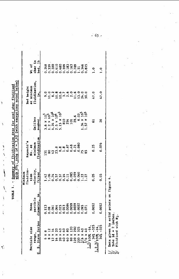
-' 65 ,-
I
w 1
3 3
~ m m m m d d V I m m V I m N V I d 49)- m 4 o o o o \ o h
000000000000 ". 9.9 7! 3 ? 9 3 9 9 9 3
3 4
3 P- d
d W
VI m 0
? 0
m VI 0
0 9
9 rl
? PI d
'0,
\o P- O
0
m
0 3
m In 0
0 9
*
8

- 66 - where prec ise d e f i n i t i o n of Umf was d i f f i c u l t . ga t ion was noted with the p a r t i c l e s i z e range i l l u s t r a t e d i n f igu re 6b, but t h i s could be overcome by going t o v e l o c i t i e s cons iderably higher than Umf where per- formance s t a b i l i z e d even with the r e l a t i v e l y high L/D r a t i o used i n t h i s t e s t .
b s i ~ n cons idera t ions . To design a fluid-bed chemical r eac to r , i t is genera l ly no t s u f f i c i e n t t o know only Umf because one must opera te a t a ve loc i ty s u f f i c i e n t t o give vigorous mixing and prevent the segrega t ion of p a r t i c l e s . p a r t i c l e s i ze ranges, i t was found that a gas v e l o c i t y twice t h a t of Umf was s u f f i c i e n t t o provide good mixing and t o prevent segrega t ion . above, f o r the wide p a r t i c l e size d i s t r i b u t i o n (100 percent -14 t o 34 percent -325) i n t ab le 1, i t was necessary t o opera te a t U/Umf>7 before complete mixing was achieved.
Appreciable channelling and segre-
With the narrow
However, as mentioned
To ca l cu la t e the mean s o l i d s residence time in a f lu id-bed r eac to r requi res knowing t h e amount of bed expansion as a func t ion of opera t ing condi t ions . The da ta below ind ica t e tha t the expansion r a t i o depends on the mean p a r t i c l e s i z e as well a s U / U m f . A summary of experimental r e s u l t s is shown in f igu re 7a and 7b where L/L,,,f is p lo t t ed aga ins t U/Umf f o r various p a r t i c l e s i z e s . decreases , so does the bed expansion r a t i o f o r a f ixed U/Umf u n t i l dp reaches about 0.025 i n . , below which f u r t h e r reduct ions i n p a r t i c l e s i z e do no t change the expan- s ion behavior. For wide p a r t i c l e s i z e ranges, the previously defined mean diameter determines the bed expansion as is ind ica ted i n f igu re 7b where expansion r a t i o s f o r f l u i d beds having cha r p a r t i c l e s from 14 to325 mesh a r e p lo t t ed . 7b, da t a a re shown f o r narrower p a r t i c l e s i z e d i s t r i b u t i o n tests made w i t h p a r t i c l e diameters below .025 inch .
A s the mean p a r t i c l e s i z e
Also i n f igure
CONCLUSIONS
The minimum f l u i d i z a t i o n ve loc i ty of coa l cha r s , phys ica l ly similar t o those studied he re , can be predic ted f o r var ious p a r t i c l e s i z e s and gas condi t ions by computing 7 t h e Gal i leo number and f i t t i n g it t o the c o r r e l a t i o n developed here . To ge t the Ca l i l eo number r e q u i r e s knowledge of mean p a r t i c l e s i z e , p a r t i c l e dens i ty , and gas dens i ty and v i s c o s i t y a t condi t ions f o r the des i r ed system. t o both narrow and wide p a r t i c l e size d i s t r i b u t i o n s and over a range of "Reynolds numbers a t minimum f l u i d i z a t i o n " from less than 0 .1 t o over 100. The minimum f l u i d i z a t i o n ve loc i ty p red ic t ed by our experimental c o r r e l a t i o n is considerably h igher than one would c a l c u l a t e from e x i s t i n g theory and from o the r co r re l a t ions because of small agglomerates i n the char which causeentanglement and thus requi re an add i t iona l energy inpu t t o e i t h e r s epa ra t e them o r f l u i d i z e the more massive combination. Cor re l a t ions are a l s o presented f o r f lu id-bed expansion tha t ind ica te t h a t the mean p a r t i c l e s i z e is the main f a c t o r i n determining how bed expansion w i l l
The c o r r e l a t i o n appl ies '
1
r vary with gas v e l o c i t y . /
NOTATION
U - s u p e r f i c i a l gas v e l o c i t y , f t / s e c
Umf = s u p e r f i c i a l gas v e l o c i t y , a t minimum f l u i d i z a t i o n , f t / s e c
op - dens i ty of f l u i d phase, lb/cu f t
ps - e f f e c t i v e dens i ty of s o l i d phase, lb/cu f t
:
= bulk dens i ty of bed, l b / cu f t
:t

- 67 -
dp mean p a r t i c l e diameter , f t - gas v i s c o s i t y , l b l f t - s e c
Ws = weight of s o l i d i n bed, l b
AT = c r o s s s e c t i o n a l area of tube , sq f t
AP = pressure drop a c r o s s bed, l b l s q f t
L - bed h e i g h t , f t
Lmf = bed h e i g h t a t minimum f l u i d i z a t i o n ,
DT - tube diameter , f t
g = a c c e l e r a t i o n of g r a v i t y , f t / s e c 2
N a = G a l i l e o number = dpPf(ps-pf) gp-2
d p i - p a r t i c l e d iameter , f t
X i = weight f r a c t i o n of p a r t i c l e s having diameter d p i '
?
t
( N R ~ ) = Reynold's number a t minimum f l u i d i z a t i o n
1.
2.
3 .
4.
5.
6.
REFERENCES
Wen, C . Y. and Y. H. Yu. Chem. Eng. Prog. Symposium S e r i e s , v . 62, No. 62, 1966, pp. 100-111.
Jones, J . F . , R. T. Eddinger, and L. S e g l i n . Proceedings of I n t e r n a t i o n a l Symposium on F l u i d i z a t i o n , Eindhoven Nether lands , N.U.P. Amsterdam, June 6-9, 1967, published by Nether lands Univers i ty , Amsterdam.
Curran, G. P., and E v e r e t t Gorin. S t u d i e s on Mechanics of Pluo-Sol ids Systems. Per iod July 1964 t o June 1968, R & D Report No. 16, I n t e r i m Report No. 3, Book 1, OCR Contract 14-01-0001-415, Consol ida t ion Coal Co., Research Div is ion , L i b r a r y , Pa.
Feldmann, H. P., W. H. Simons, J . A. M i m a , and R. W. Hiteshue . ACS Div. of Fuel Chem. P r e p r i n t s , v . 14, No. 4, P a r t 11, pp. 1-13, Sept . 1970.
Leva, Max. F l u i d i z a t i o n , M c G r a w H i l l Book Co., I n c . , N . Y . 1959, pp. 60, 61.
Ergun, Sabr i . Anal. Chem., v . 24(2):388 (1952).
ACKNOWLEDGEMENTS
The h e l p of Mr. David A . Williams and Mr. Joseph A. M i m a i n conduct ing t h e exper i - ments and the h e l p f u l advice of D r . C. Y . Wen are g r a t e f u l l y acknowledged.

- 68 -
FIGURE 1.- Cross S e c t i o n of T y p i c a l Char P a r t i c l e a t 220 Magn i f i ca t ion .

- 69 -
cn w .- W
0 0 N - u C E?Q
c n c a , o 0 E
In - 2 ? a r
C 0 .-
.- t .-
; ; o C
I- - 0 0 c In d- r
0
0
0
0
0
0 0 - - 0 N
E +4 /q l ‘sd‘AIISN3a a 110s


- n -

- 72 -

- 73 -
I 1 ’ 1 I I I I I I I I I ’ - AT
- - ----- F -x.*R--.mWI.X--. x x+
P’ - - -
y: =/I
-
- - i - -/K
- - - - - - - Particle site range, (14 x 20) -
Fluidizing gas=CO, x increasing velocity
- - - 0 decreasing velocity -
- - -
-
1 I I I I I 1 I I l l I I I I I I I 0.2 0.4 0.6 0.8 I 2 4 6
40
30
20
IO 9
Ow 8 7
O, € 6 a a 5
4
I
3
2
I
FIGURE 6 a . - Typical Pressure Drop-Velocity Curve, Narrow P a r t i c l e S i z e Range.
L- I22 33

- 74 -
40 I I 1 I I I I I I I I I ! I I I I I I I 30 -
*S - - -
g-0.. *Lho--~.+&f*qpp- x h % o 20 -
-
IO - - - - E 6 - - a a 5-
7
- 4 -
3 -
- Part ic le size range (100%-14,34”/ , -325)
Fluidiz ing gas= N, Fluidizing gos=CO,
increasing velocity o increasing velocity
- - -
2 - x decreasing velocity D decreasing velocity -
I ,
- -I
I I I I I I I I I I I 1 I I . I I 1 1 1 1
u,f t/sec
FIGURE 6 b . - Typica l Pressure Drop-Velocity Curve, Broad P a r t i c l e Size Range.
L-12234
r

- 7 5 - -

- 76 -
- 7 7 -
STUDIES ON THE PRODUCTION OF CARBON BLACK FROM COAL
M.S. Iyengar, R. Haque, R. K. Chakrabarti and M. Le Dutta
Regional Research Laboratory, Jorhat , ( A s s a m ) , India
\ ABSTRACT
Ear l ie r work revealed t h a t high v o l a t i l e , v i t r a i n r i ch and low ash coals could be converted t o carbon black equivalent t o thermal grade carbon black of commerce. In the present paper which is an extension of the e a r l i e r work some other coa ls have been used. It has been shown t h a t by changing the reac tor design and reaction var iables the carbon black obtained i s found t o have propert ies of rubber and ty re grade products. Propert ies and com- pounding tests of t h e carbon black in rubber m i x have been ca r r i ed out and compared with those of standard products. A cos t economics of the carbon black obtained from coal has a l so been discussed.
1
1
!

- 78 -
Coal has t r a d i t i o n a l l y been used as f u e l s and there are very Johnson and co- few studies describing the nonfuel use of coals.
workers (1,2) were the f i r s t t o repor t on the conversion of high v o l a t i l e coa ls i n t o thermal black. They obtained the black a s a byproduct i r ? thc ?reduction o f hydrocyanic acid from coal. In an e a r l i e r paper (3) the present authors have described the production of thennal black from r l ~ ~ a m coal. They adopted a t ransport reactor very much d i f f e r e n t t o t h a t used by the earlier workers and the i r main product was carbon black.
eu t thermal blacks f ind very l imited use. f o r rubber grade black f o r use i n the t y r e industry. paper describes s tud ies on obtaining improved grades of carbon black from three bituminous coa ls of India. techno-economic aspec ts of producing carbon black from coals.
auipment and t_h_e_ process:
!Mle the apparatus in the present s tud ies a r e similar t o tha t described earlier (?), the reactor , Powevcr, was designed t o handle 70 lb./bour of coal . t l d c k high a lw. ina b r i cks followed by a 6 in . layer of insulat ion br ick f o l l o w d by a L.3. sheet. The reac tor was 12 f t . high and 1 ft. i n diamc ter.
The major dpmand i s
The paper a l so describes the
The present
r
The inner wall of t he reactor was made of 9 i n .
A t yp ica l run tias carr ied out as follows:- r
CrUsk~eZ coal (40 per cent through 200 3 2 ) fed t o t h e reactor through 3 ro ta ry feeder i s coriveyed tnrough t h e transport reactor by LIe c a r r i e r gas air. 500 - becomes steady a t the above temperature, t he charging of coal i s s ta r ted . 1300°C maximm. constant a t 65 cu . f t . / lb . and the t i m e 'of residence of the coal p a r t i c l e s i n the reac tor i s about 1.3 secon'ds. The 'carbon blacl.: i s col lected ir! the temperatGre range of 1300 - 13OO0C. The char i s separated from carbon black i n a s t a in l e s s s t e e l cyclone separator. The carbon i s recovered by f i r s t scrubbing i t with water i n the scrubber and then by e l ec t ros t a t i c prec ip i ta t ion .
The product is then pe l l e t i s ed and dr ied a t 400 - 4 5 O O C . S t r i c t control of a i r / c o a l r a t i o and feed r a t e a r e important a s changes may lead t o existence of uncrc?cl:rd t a r i n the cerbon black. and de ter iora te i t s property o r lead to cxcessive combustion and g ive lower y i d d of the product. P i F r e 1 S.-OWS the un i t €or pro- d.ucin.5 carbon black from coal.
Experimental Le-silts and discussion - formed under widely varying geological conditions. t h e analysis of t h e coa l s used i n the study.
The reac tor i s i n i t i a l 1 h e a t e d t o
P a r t i a l conbuztion 05 . the ~02.1 raises the taqera tur .e t o
600°C by burning low ash firewood. &en t z e temperature
The a i r t n coal r a t i o of the charges is kept
The vork was cErri& out with three d i f f e ren t coa ls of India Table I s h o ~

I . - 79 - Though they are a l l high v o l a t i l e low rank coals , they d i f f e r
i n t h e i r caking c h a r a c t e r i s t i c s and ash content. of t h e t h i r d coal i s much lower than t h e two o the r coals. Reaction conditions were maintained i d e n t i c a l and average test r e s u l t of two or t h ree runs has been shown. blacks.
r e l a t ionsh ip with the hydrogen content of the coal . a l s o obtained such r e l a t i o n s (41, but d e t a i l s of t h e i r process are n o t avai lable .
. involves decomposition of coal t o tar and gaseous hydrocarbons which ul t imately undergoes dehydrogenation and aggregation to form carbon black. Theories on t h e carbon black formation d i f f e r mainly i n the rou te and order i n which these two e s s e n t i a l changes occur ( 5 ) .
product. only low ash carbon b h c k produced frcnn Baragolai c o l l i e r y coal , U per Assam. b!ack produced from Baragolai c o l l i e r y coal (a> and HAF black(b1. The study was ca r r i ed out using a magnification of 52700 t o de te r - mine the average p a r t i c l e s i z e and the s t ruc ture of the black. It i s observed that carbon black obtained from coal i s of high structwe and i s d i f f e r e n t from thermal black, which i s a l s o supported by i t s compounding test. The size of these p a r t i c l e s varies from 200 - 800° A comparable w i t h HAF blacks having particle size varying between 200 - 800OA. However, the frequency of d i s t r i b u t i o n of bigger p a r t i c l e s i n the HAF black i s much less than those i n carbon black prepared from coal.
Sulphur content
Table I1 shows t h e a n a l y s i s of carbon
Figure 2 shows that t h e y i e l d of carbon black bears a direct The iiussians
The formation of carbon black from coa l i n i t i a l l y \
Coals containing high mineral matter give a higher a sh i n the Consequently canpounding tests have been c a r r i e d o u t with
Figure 3 shows the e l ec t ron micrographs of carbon
\ Figure 4 shows the x-ray pa t t e rn of carbon blacks obtained fron , (1) Baragolai c o l l i e r y coal , (2) Pench Valle coal , and (3) Standard
Sam l e HhF. o a f s show bands of mineral matters, e spec ia l ly more prominent i n t h e case of sample 2 obtained p" rom Pench V d l e y coa l containing higher percentage of mineral matter. of sam l e s 1 and 2 d i f f e r i n i n t e n s i t y f r c a that of number 3 as the formatron of the latter takes place a t temperature Figher than those of 1 and 2. This may be a t t r i b u t e d t o the randomness in t h e degree of o r i en ta t ion of carbon p a r t i c l e s i n s m n l e s 1 and 2 whose formation takes place a t lower temperature than that of sample 3.
It may be observed that the car g on blaclcs obtained from r t z , which is
The carbon band
\\ ,
/ Prope r t i e s of t h e carbon black obtained from Bara o l a i c o l l i e r y coa l , Assam have been compared with two commercial c a r b n blacks i n Table 111.
Acetone e x t r a c t which ind ica t e s the presence of uncracked tar i n the product i s s l i g h t l y higher than those of t h e standard blacks. Iodine absorption values are ,=eater than even P3.F blacks. Surface area has been calculated from iodine absorption values (61, using t h e r e l a t ionsh ip SDd = 60,000, where S = surface area, D = density, d = a r t i c l e size. D.B.P. absorption i s very nea r ly equal t o the HAF h a c k s but greater than t h e 313 blacks pH of the product i s i n t h e mild a c i d i c range which may be a t t r i b u t e d t o t h e nature of s t a r t i n g material.
? ,'

- 80 -
Table I V shows the physical properties of rubber compounded with carbon black obtained from Barapolni co l l i e ry coal and com ared with those compounded with a standard d%F black. llooney viscosrty which is an iniportant propcrty of the polymer mix is d ondant mainly on the carbon black s t ruc ture and loading in most $reus. I n a 50 phr sample Nooncy viscosi ty 4 100a2 is found to be i g er than the 3!W blacks and I!ooney scorch time about 0.64 times tha t of SW blaclcs.
Rate of cure of the compound loaded with carbon black derived from coal is f a s t e r than compounds loaded with 513 blacks.
Physical rope r t i e s like t ens i l e streneth, elcngation a t break and 300% modurus of the compound loaded with carbon black f r an coal are i n l ine with A Y blacks, wilich shows it can subs t i tu te SRF blacks,
Cost economics:
t h e cos t of production is $ 70 per ton on the bas i s of 20 per cent conversion of coa l t o carbon black and price of coal being taken $ 7.5 per ton. The price of char produced i n the process (about 30 per cent) is taken as $ 10.00 per ton. This is qui te r a i s i n g as the market price of carbon black i n India va r i e s from ! 225 - 325 per ton.
Conclusion - By changing the design and material of construction and a l t e r ing
t h e reaction var iables the quali ty of the carbon black obtained from coal can be considerably improved t o approach those of t he rubber grade product. Though the physical pronert ies fib t e n s i l e strength, elongation a t break and 300 p e r cent moJulus of the compound loaded with carbon black f r m coal are lower than the compounds loaded with iciF blacks, they are i n l i n e with the SA.? b1acl.x. t o produce TZL' black.
.kkr.owl cd.%qze-; :
Limited, lhnbay and iTational I'hysical Laboratory, !:ew 3elhi for ass i s tancr and co-operatioc.
-------- A cost study of carbon black produced from coal revealed tha t
--
Some of tlic pro o r t i e s a re similar t o those of 'M.
hperiments are s t i l l underway
Gratei'ul ac laor~1ed~~; l len t i s made t o i ;/s Synthetics and Chemicals

- 81 -
- L i t e r a t u r e Zit&:
') I. Johnson, G.E. Decker, W.A., Forney, LJ., Field, 3.H. 158th National Meeting of American Chemical SOC. Division of Fuel Chemistry, N e w York, Sept. 7 - 12, 1969, Vol. 13, No. 3, pp.207-222.
2. Johnson, G , E , Deckar, V.A., Forney, A.J., Fie ld V.H. Rubber
3. Hague, R., Chakrabarti, R.K., mtta, M.L., Iyengar, M.S.
'Jorld, 156(3), 63-68, 1967.
publicat ion in J. Ind. h g . &em. R & D Section (under review). Sent for
-_ 4. Mischenlco, M.L., Bagdanov, I.F., Farberov, T.L., Urkovski,
I.M., Gilyazetdinov, L.P., Gugaev, B.I. (21, 139- 141 (Mar-Apr., 1969).
K h h , Tverd. Topl. 8
5. Caydon, A.G., "The Spectroscopy of flames". Chapman & Hall
6. Smith, V.X., Thornhill, F.S., Bray, R.I., Snd. '&go Chem.
Ltd., London, 1957, p. 189.
Indust. , 33, 1303 (1941).
Table I - Analysis of the coa l s used for production of carbon black.
1. Baragolai 2.7 1.8 4 2 . 3 57.7 81.4 5.6 2.5 10.5 Wghly ' c o l l i e r y , caking.
Upper Assam
' 2. Garo H i l l , 6.5 1.4 49.5 50.5 8 0 . 3 5.8 2.5 11.4 Weakly Lower Assam caking.
' 3 . Pench 23.4 4 . 5 35.0 65.0 82.5 5 . 2 0.7 11.6 Non- V a l 1 ey , caking. 1 14.P.

- a2 -
Table I1 - Analysis of carbon blacks produced from di f fe ren t
Coal feed rate - 70 lb , /h r .
Xirlcoal r a t i o - 65 cu. € t . / l b .
Tenperature range of col lect ion of carbon black - 1200 - 1300OC.
coa l s under react ion conditions. I
, -7 1 I 1 I 1 1 I Carbon black ob-XYieldXXsh LYois- XV.11.X F.C.1 C ta ined from X 7, X 2 Xture %I X X % X 7. X % X 'Z X d i f f . )
H X 3 X N+O (by
1. Baragolai 20 1.3 2.0 2.2 94.5 95.8 0.7 1.6 1.9 co l l i e ry , Upper Assam.
Lower Assam.
K.P.
2. Gar0 F i l l , 22 4.2 2.5 2.6 90.7 95.4 0.8 1.7 2.1
3. Pench Valley, 14.418.3 1.4 3.8 76.5 94.7 0.7 0.4 4.1
Table I11 - Propert ies of carbon black obtained from Assam coal compared with those of commer- cial carbon black.
2 UcetonelIodine . . . I I I Carbon black XextractXabsorptionIabsor- XParticleXSurfac5 pH obtained from X 7 Xvalues Xption valuesrsize, Xarea M I
1. Baragolai 1.9 89 10 6 200 - 800 68 6.5 t o '
- X mg./p. Xm11100n. X Or? X P;. x
colliery 7.0 coal , Upper Assam.
2. S?S black 0.4 30 70 - 80 600 - 800 25 - 30 6.0 - 6.5 J!,
3. HA1.' black 0.5 82 1034 200 - 800 74 -100 8.0 - - 9.0
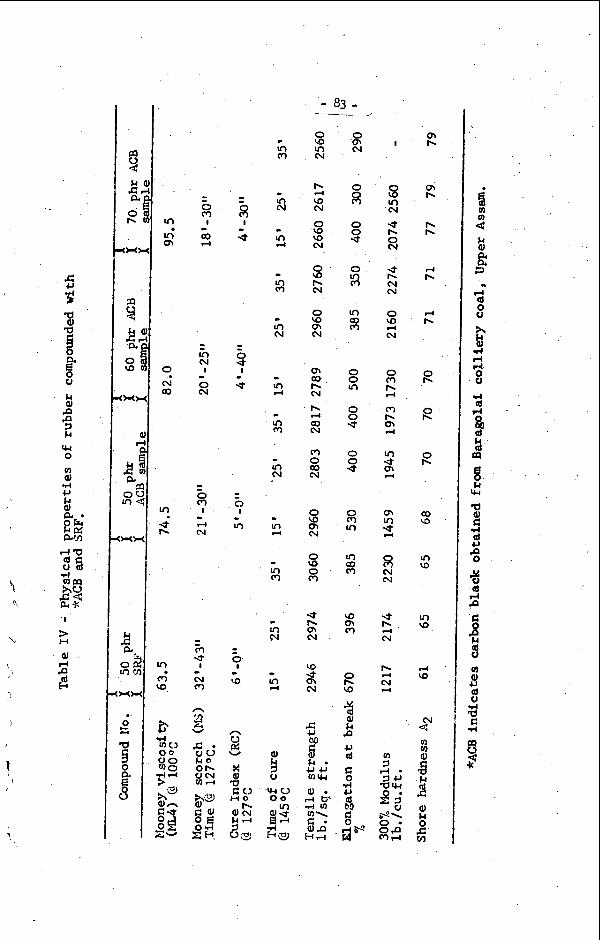
- 83 - -
0 QI hl
z 0 s 0 m rr)
In co m
0 0 m
0 0 * 0 0 .j
8 m
VI co m
\o m m
0 h \o
% 9) k P c, cd c 0 1-I u (d bO
4s W 5
m h
oi h
I h h
3 k rl h -
In m
d h -
m N
0 h -
0 N
0 h
0 h -
m N
I
d hl
- W a - In d
v, m I \\
In \o 0
m N \,
\
N c n U p: v 3 d
k 0 O h V h l v l d
9) k 0
6

- 8 4 -
W u 0 0 * ;I:
a
(1VO3 dO l M 3 3 Y 3 d ) m v i a N O Q Y V ~ JQ O ~ I A
(u
1'
,
J

- 85 -
\

- 86 -
( 3 )
t
Figure 4. X-ray diffraction patterns of t he carbon blacks obtained from (1) Baragolai coll iery coal, Upper Assam (2) Pench Valley coal, M.P., (3) HAF black.