The Jump Jacket MK4 - AP Diving · The Jump Jacket Mk4. has four independent gas supplies...
28
Version June 2008 The Jump Jacket MK4 Instruction Manual Produced by Gary Jones and A.P.Valves
Transcript of The Jump Jacket MK4 - AP Diving · The Jump Jacket Mk4. has four independent gas supplies...

Version June 2008
The Jump Jacket MK4 Instruction Manual
Produced by Gary Jones and A.P.Valves

Version June 2008 1
JUMP JACKET MK4
THE JUMP JACKET Mk4
INTRODUCTION
The Jump Jacket Mk.4 has been designed to be used in the commercial diving industry, specifically for surface air and mixed gas diving, to allow the diver total control of his buoyancy. The emphasis has been heavily placed on safety and efficiency, allowing the diver greater flexibility under water without drawing on emergency energy levels. Expanding on the safety features of the MK.3 Jacket, the general concept is to give the diver more control of his buoyancy and expand his options in an emergency situation.
GENERAL DESCRIPTION
The Mk.4 Jacket has been designed to be used in conjunction with a KMB.17 b/c diving helmet. As well as the normal buoyancy control and performance expected of the previous jackets, the Mk.4 offers direct feed supply to the jacket from the divers main gas supply, also an emergency supply from the diver’s bailout. Another safety feature is the ability to buddy breathe two divers from one umbilical supply in an emergency situation.
With the incorporation of a helmet safety harness, the Mk.4 Jump Jacket is the only stand alone commercial diver’s buoyancy control unit that incorporates a full recovery diver’s harness, helmet harness and bailout backpack.
The Mk.4 Jacket has been designed to be used with an umbilical supply, but can be used independently if required. The pressure relief /dump valves allow the Jacket to be passed in and out of diving systems without rupture or damage to the inner bladder and gives the diver total control of his buoyancy.

Version June 2008 2
JUMP JACKET MK4
CONTENTS
1. THE JACKET
1.1 Donning 1.2 Gas supply
1.2.1 Main Gas Supply (Umbilical) 1.2.2 Secondary Gas Supply (Pneumo Valve) 1.2.3 Emergency Bailout Gas Supply 1.2.4 Diver to diver (Umbilical cross connect) 1.2.5 Inflation Cylinder 0.4 lt.
2. OPERATION
2.1 Buoyancy control 2.2 The Harness 2.3 Diving Helmet Safety Harness
3. DIVER RECOVERY
3.1 Diver Recovery (Unconscious Diver) 3.2 Diver Recovery (Trapped Diver)
4. TRAINING
4.1 Training (Diver) 4.2 Training (Technician)
5. MAINTENANCE AND COMPONENTS
5 General 5.1 Outer Jacket 5.2 Inner Bladder 5.3 Harness 5.4 Main Supply Valve 5.5 Dump/Pressure Valve 5.6 Pneumo Valve (pre 1999) 5.7 Pneumo Valve (pre 2008) 5.8 Pneumo Valve (2008 on) 5.9 Helmet/Jacket Q.C. Fittings 5.10 Snap Connectors 5.11 Cam Buckle (Cylinder Quick Release)
5. PART NUMBERS

Version June 2008 3
JUMP JACKET MK4
INSTRUCTIONS FOR OPERATION AND USE
1. 1.1 DONNING
The Jump Jacket is designed to be worn as a single unit without the need for any other harnesses. With the jacket and bailout supported, the diver steps into the continuous loop leg straps and then passes his arms through the waistcoat jacket. Ensure that the primary lifting D ring is accessible between the diver’s shoulder blades. The waist, chest and leg straps can now be adjusted for a comfortable fit.
1.2 GAS SUPPLY
The Jump Jacket Mk4. has four independent gas supplies available:
1.2.1 MAIN GAS SUPPLY The main gas supply comes from the main umbilical via the helmet sideblock. A quick connect system is used to supply the gas down to the jacket supply valve, situated on the right hand wing of the jacket. This offers an unlimited gas supply to the jacket at any time.
1.2.2 SECONDARY GAS SUPPLY (PNEUMO VALVE) The second supply is from the Pneumo valve, which is connected to the Pneumo hose via an openended quick connect Swagelok fitting. This can be used anytime there is Pneumo gas supplied to the diver. It is recommended that the Pneumo hose is blown clear of water before injecting into the jacket, as this could result in water ingress into the jacket.
1.2.3 EMERGENCY BAILOUT GAS SUPPLY The third supply offers the option of using the diver’s bailout gas supply in an emergency. This is a oneoff supply to the jacket and should only be used in the event of losing the main gas supply or a severed umbilical. One inflation of the jacket from a fully charged bailout at a depth of 160 metres would reduce the bailout duration from 5mins 30s down to 4mins 56sec. A deficit of 34 seconds.

Version June 2008 4
JUMP JACKET MK4
INSTRUCTIONS FOR OPERATION AND USE (cont.)
1.2 GAS SUPPLY (continued)
1.2.4 DIVER TO DIVER (UMBILICAL CROSS CONNECT)
The umbilical cross connect is used in an emergency situation and allows two divers to buddy breathe from one umbilical gas supply. This is achieved by disconnecting the quick connect fitting from the jacket supply valve of one diver, disconnect the quick connect fitting on the second diver’s helmet and connecting in the first diver’s jacket supply hose to the second diver’s helmet. (See Fig. 1) The two divers are now able to breathe from the one umbilical. N.B. The quick connect fittings are supplied with core valves and so no loss of gas should be experienced during this operation.
Fig. 1
1.2.5 INFLATION CYLINDER 0.4 lt. An emergency 0.4lt cylinder is fitted to the rear right quarter of the jacket and can be used when surface orientated diving. This is not to be used when bell diving due to the possibility of gas contamination.

Version June 2008 5
JUMP JACKET MK4
INSTRUCTIONS FOR OPERATION AND USE (cont.)
2. OPERATION
2.1 BUOYANCY CONTROL
The Jump Jacket offers a maximum buoyancy of 22.72kg. Control of jacket buoyancy is achieved by a combination of the diver injecting gas from his chosen gas supply and dumping gas via either dump valve. Choice of gas supply would be dependent on the diving setup and the situation that the diver finds himself in.
As gas is injected, the diver should grasp one of the two dump cord toggles, situated on either shoulder of the jacket. By operating the gas supply and dump valves in sequence, the diver will be able to achieve his required state of buoyancy.
Operating either dump valve will empty all the gas from the Jacket in three seconds.
At typical working depths of 100150+m a fully inflated Jump Jacket will make the diver only slightly positively buoyant. In other words, there is no risk or danger to the diver of a rapid uncontrolled ascent occurring as a result of inflating the jacket. Buoyancy changes happen very slowly at depth.
To perform a controlled ascent, the diver increases his buoyancy to a positive state. As he starts to ascend the gas inside the jacket will expand in accordance with Boyles Law. To control this, the diver must manually dump gas out of the jacket to continue his ascent at the required rate. If the diver fails to dump gas and the jacket reaches full capacity, the pressure relief valves will operate and dump gas out of the jacket arresting the ascent. With a correctly maintained Mk4 Jump Jacket it is virtually impossible to achieve an uncontrolled ascent from depth to the surface.
A third dump/pressure relief valve is situated on the lower, left rear quarter of the jacket. This can be used to dump gas from the jacket if the diver finds himself in an inverted position. This valve can also be used to drain any water that may have entered the jacket at the end of each dive.
2.2 THE HARNESS
This is a new design diving safety harness. The main lifting point is positioned between the diver’s shoulder blades and is fitted with a large handle D ring to assist in the normal recovery of the diver. (See Fig. 2)

Version June 2008 6
JUMP JACKET MK4
INSTRUCTIONS FOR OPERATION AND USE (cont.)
A second lift point is provided by means of two harness extensions, positioned inside the front wings of the jacket and can be pulled together to form a front lifting point. (See Fig. 3)
Fig.2 Fig.3
The harness has two umbilical D ring positions and diver rigging D rings on the leg straps. For safety reasons the leg straps are permanently fitted through the roller/adjuster buckles, forming permanent loops that the diver will have to step into when dressing. This harness is only to be used in conjunction with the Jump Jacket and is not recommended for any other use.
2.3 DIVING HELMET SAFETY HARNESS
The provision for a diving helmet safety harness has been incorporated into the Mk.4 Jacket for those helmets fitted with the safety clips. This frees the diver from wearing any form of helmet harness. This attachment comes in the form of a set of D ring and webbing strops fitted to either shoulder of the jacket. The helmet safety clips are attached to this to prevent the diver losing his helmet should the Neckdam fail.
N.B. This is not designed as a helmet adjustment strap.

Version June 2008 7
JUMP JACKET MK4
INSTRUCTIONS FOR OPERATION AND USE (cont.)
3. DIVER RECOVERY
The Mk4 Jump Jacket has been designed to assist in the recovery of an injured, unconscious, or trapped diver.
3.1 DIVER RECOVERY (UNCONSCIOUS DIVER)
The use of the Mk.4 Jump Jacket to assist in an emergency diver recovery as been greatly advanced. The ability to float an unconscious diver back to a diving bell or recovery basket has proven to be a major safety feature. The bellman/standby diver is able to use the unconscious diver's Jump Jacket to lift him above the seabed or obstruction and then concentrate his efforts on the horizontal pull back to the recovery position.
An unconscious diver can first be recovered on the main primary lifting point into the bell, then be transferred onto a standing webbing strop clipped into the secondary front lifting position of the harness. As the main lift is slackened off, the weight will be taken on the secondary lift, causing the diver to pivot backwards, tilting his head and allowing his airway to open. (N.B. The diver’s Neckdam may be removed at this point). This position has been proved to be of greater benefit when administering EAR., cardiac massage and first aid and also in assisting in securing the diver in the bell after recovery. (See Fig.2)
When the diver recovers consciousness or at any time prior to this, the bailout cylinders maybe removed using the Jump Jacket’s quick release Cam buckles to allow better access and handling of the diver. (See Section. 5.1.0)
3.2 DIVER RECOVERY (TRAPPED DIVER)
A diver finding himself trapped by his umbilical at any time is a serious situation. The primary concern would be for the condition of the trapped diver and the integrity of his main gas supply. Secondary concerns would be hypothermia due to loss of hot water, unstable loads and Vessel D.P. runoff. Therefore, we can see it is very important to be able to remove the diver from this situation as quickly as possible. The gas supply to the Mk.4 Jump Jacket has been designed to assist in a two man dive, where one diver is able to recover the second diver back to safety, assuming the first diver is not trapped or injured. The first diver would approach the second diver and assess the situation. If the second diver has gone on to bailout gas supply or the main umbilical gas supply been interrupted, the buddy breathe crossconnect can be employed using the following method:

Version June 2008 8
JUMP JACKET MK4
INSTRUCTIONS FOR OPERATION AND USE (cont.)
a. The Recovery Diver would disconnect the quick connect fitting and jacket supply hose from the helmet side block of the Trapped Diver.
b. Disconnect the quick connect fitting from the Recovery Diver’s inflation valve to his jacket (See Right)
c. Pull out the extended inflation hose from the Recovery Diver’s jacket pouch and connect the jacket inflation hose into the Trapped Diver's helmet sideblock quickconnect fitting. The Trapped Diver is now breathing from the Recovery Diver’s main umbilical gas supply.
d. The Trapped Diver's main umbilical can now be cut to allow his recovery back to the bell.
N.B. During this operation, the gas supply from the Recovery Diver’s jacket supply hose and each diver’s helmet is protected by doubleend shutoff valves in the Swagelok quickconnect fittings. Therefore, the connections can be made and broken under pressure with no loss of gas to either diver.
4. TRAINING
It is recommended that each Company using the Jump Jackets should set up a training and maintenance program for diving and technical personnel to comply with the HSE Code of Competency. Training courses can be arranged through A.P. Valves. Contact: 01326 561040
4.1 TRAINING (DIVER)
It is very important that each diver is given a full briefing into the operation and use of the Jump Jacket prior to inwater use. For the diver’s first inwater dive with the jacket, it is recommended that he be accompanied by a diver who is fully conversant with the use of the Jump Jacket.

Version June 2008 9
JUMP JACKET MK4
INSTRUCTIONS FOR OPERATION AND USE (cont.)
Time must be allowed during a course of operational dives for those divers who are new to the Jump Jacket to explore the versatility of the jacket at their own pace. Each diver will experience a different learning curve before building up enough confidence to use the jacket to its full potential.
4.2 TRAINING (TECHNICIAN)
Equipment Technicians should be fully trained on all aspects of the Jump Jacket and be able to implement a full service and maintenance program. It is recommended that the following maintenance program be employed for the Jump Jacket:

Version June 2008 10
JUMP JACKET MK4
MAINTENANCE AND COMPONENTS
5. GENERAL
A regular maintenance program should be followed to ensure reliability of the jacket through its working life. It is recommended that the jacket be taken out of service and visually inspected for damage or wear approximately every 10 15 dives or in conjunction with the diving helmet maintenance program. The jacket can be hand washed in a mild soap water solution. A porosity test should be carried out to confirm integrity of the inner bladder and valves. All valves should be cleaned and serviced. Any damaged parts should be replaced immediately.
N.B. No liability can be accepted by the manufacturer if any unauthorised alterations are made to any part of the jacket, valves or harness.
DAILY (DIVER)
1. Check jacket for damage and wear. 2. Check harness for damage and wear 3. (Air diving only). Charge 0.4 lt. cylinder to 232 bar. 4. Inflate jacket via Pneumo valve. 5. Check operation of Pneumo valve. Rinse out with fresh water. 6. Check dump/pressure relief valves x 3. Rinse out with fresh water. 7. Check dump valve cords for wear. 8. Check jacket for leaks. 9. Drain any water from jacket via lower dump valve. 10. Carry out inwater check for leaks. 11. Flush Pneumo and dump valves with fresh water after each dive.
MONTHLY (TECHNICIAN)
1. Check 0.4 lt. cylinder Test Date. 2. Remove dump/pressure relief valves. Service them and refit to jacket. 3. Remove Pneumo valve. Service, replace orings and refit to jacket. 4. Flush inner bladder with fresh water via dump valve and Pneumo valve
ports while valves are removed.
SEMI ANNUAL (TECHNICIAN)
Return to base for Inspection.

Version June 2008 11
JUMP JACKET MK4
MAINTENANCE AND COMPONENTS (cont.)
5.1 OUTER JACKET FRONT
Adjustable Shoulder Buckle
AP5 Knob
Secondary gas supply via Pneumo valve JJ1
Main gas supply via helmet
Swagelok Snap Connector
Waistband adjustment JJH/1
Harness JJH
BACK
AP5 Exhaust Valves
Helmet Straps
Inflator Hose from KMB. 17bk helmet
BK15, BK16, BK17

Version June 2008 12
JUMP JACKET MK4
MAINTENANCE AND COMPONENTS (cont.)
5.2 INNER BLADDER

Version June 2008 13
JUMP JACKET MK4
MAINTENANCE AND COMPONENTS (cont.)
5.3 HARNESS

Version June 2008 14
JUMP JACKET MK4
MAINTENANCE AND COMPONENTS
5.4 MAIN SUPPLY VALVE
Manual Inflator Assembly:
Item Reference Description 1 RB05/01 Valve Body 2 RB05/02 Sticker 3 JJ13 Swagelok Stem 4 RB05/05 Insert 5 RB05/06 Spring 6 RB05/07 Button 7 AP15 Protector 8 AP35D Lock Ring 9 AP35E Cylinder Post Base 10 AP35L Inner Lock Ring 11 AP400/3 Spindle 12 AP400/4 Filter 13 BS.006N70 O Ring 14 BS.010N70 O Ring 15 BS.010N70 O Ring 16 BS.222N70 O Ring

Version June 2008 15
JUMP JACKET MK4
MAINTENANCE AND COMPONENTS (cont.)
5.5 DUMP/PRESSURE RELIEF VALVES
These valves are dismantled by unscrewing the top cover of the valve body while firmly gripping the valveretaining collar inside the jacket. This will now reveal the damper diaphragm and mushroom valve. Wash out with fresh water, ensuring no grit or debris is left behind. To remove the valveretaining collar complete, push it fully into the bladder and rotate through ninety degrees and withdraw it sideways through the bladder opening. If any damage is observed to the plastic sealing face under the mushroom valve or the valve will not seal, then the whole unit should be replaced. Replace the cord if it shows any signs of fraying or damage.
AP5 DUMP VALVE (fig.3)
AP5A CORD PULL
AP5B CORD
AP5C TOP COVER
AP5D SPRING
AP5E TOP HAT
AP5F DUMP VALVE DISK
AP5G PIP
AP5H NONRETURN VALVE DISK
AP15A RUBBER BOOT
AP5J VALVE BODY
Version June 2008 16
JUMP JACKET MK4
MAINTENANCE AND COMPONENTS (cont.)
5.6 PNEUMO VALVE (Discontinued Model)
The valve is removed from the jacket by unscrewing the whole valve while holding the valve retaining collar inside the jacket. The inner valveretaining collar is removed from the jacket via the lower rear dump valve orifice, in the same way as the dump valve retaining collar.
The Pneumo valve is dismantled by firstly removing the four screws from the button retaining ring. The ring can be removed and the inflator button withdrawn allowing the valve spring to be removed. The three BS.012 70sh. Orings can now be extracted with the aid of an Oring removal tool. These Orings have a short life span due to the harsh conditions of the marine environment and therefore should be regularly replaced.
To replace the Orings you can use the inflator button to locate them correctly. Insert its stem into the injection port at the bottom of the valve. Move the end of the stem to a position just below the middle Oring recess. This will prevent the Oring from overshooting its correct position. Insert the first Oring into the top of the valve bore and use an Oring removal tool or similar object to position the O ring into the middle recess. Move the stem up to the top Oring recess and repeat the process. For the lower Oring, remove the inflator button stem and insert it into the valve body the correct way, from the top. Position the end of the stem above the lower Oring recess and repeat the fitting process.
A grit filter has been fitted to the exhaust port to reduce the wear on the inner valve components. This is removed by unscrewing the filterretaining ring using an 11mm Hex Key.
Reassemble the valve in the reverse order. Care should be taken when threading the valve into the valveretaining ring to avoid damaging the thread.
Tighten up the valve so that the side stem is pointing in the correct position to the rear of the jacket and approximately 45 degrees down from the horizontal. This will offer the diver a good handgrip position and easy access for the Pneumo hose.
The Pneumo valve side stem should be visually checked for damage and replaced accordingly.

Version June 2008 17
JUMP JACKET MK4
MAINTENANCE AND COMPONENTS (cont.)
PNEUMO VALVE (pre 1999)

Version June 2008 18
JUMP JACKET MK4
MAINTENANCE AND COMPONENTS (cont.)
5.7 PNEUMO VALVE (pre 2008)

Version June 2008 19
JUMP JACKET MK4
MAINTENANCE AND COMPONENTS (cont.)
5.8 PNEUMO VALVE (2008 on)

Version June 2008 20
JUMP JACKET MK4
MAINTENANCE AND COMPONENTS (cont.)
5.9 HELMET/JACKET Q.C. FITTINGS
The Jump Jacket hose is connected to the helmet and Jump Jacket via two sets of quick fittings and a swivel elbow. This allows the diver to use the main umbilical/bailout gas supply to inflate the jacket. The Jump Jacket Mk.4 can only be used with a KMB. 17/18 b or c type diving helmet that is fitted with a DSI drilled “B” Sideblock.
RB05/JJ Inflator Assembly (c/w RB05, JJ13/1 & JJ15)
JJ15 Swagelok (female) JJ17 Elbow
JJ16 Swagelok (male)
JJ12/1 Hose Connector JJ13/1 Side Stem
JJ14 Hose Assembly (c/w AP50P3 and JJ12/1 ends)
JJ15 Swagelok (female)
JJ20 Hose Assembly AP50P3 JJ16 Swagelok (male) (c/w JJ14 Hose Assy & JJ16 male Swagelok ends)
JJ12/1 Hose Connector
AP50C LP Hose

Version June 2008 21
JUMP JACKET MK4
MAINTENANCE AND COMPONENTS (cont.)
HELMET SIDEBLOCK
This Sideblock can be retrofitted to any of the KMB. 17/18 helmets if not already supplied and is ordered complete from DSI. (Part number 505024)
On the Sideblock, the L.P. plug is removed and the JJ17 90 ◦ swivel with Oring fitted. A quick connect body (JJ15 Swagelok Q,C.) is fitted to the downstream end of the swivel. This allows the quick connect male (JJ16 Swagelok Q.C.) on the jacket supply hose to be connected to the Sideblock.
The supply hose is then taken over the right hand shoulder of the jacket and passed through the hoseretaining pocket next to the 0.4lt cylinder pocket. The end of the hose is then connected to the Supply valve, using the same arrangement of Swagelok Q.C. fittings as the Sideblock connection.
Excess hose is then coiled up and secured in the hoseretaining pocket so that it can be pulled out with ease in the event the diver needs to connect to another diver as detailed in 3.2
DSI SIDEBLOCK
Swagelok Q.C. DSI Sideblock (JJ16) (505024)
Swagelok Q.C. Swivel Elbow (JJ15) (JJ17)
Version June 2008 22
JUMP JACKET MK4
MAINTENANCE AND COMPONENTS (cont.)
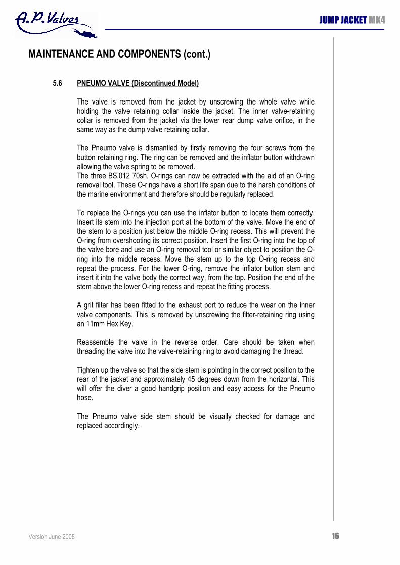
5.10 SNAP CONNECTOR
The Pneumo hose snap connector is fitted to the Pneumo hose with a no. 4 JIC female swivel hose end fitting.
The snap connector must be checked regularly to ensure it has free movement and easeoffit to the Pneumo valve side stem.
This is of vital importance as the secondary use of this hose is to provide emergency gas to the diver by disconnecting it from the Pneumo valve and inserting it under the divers neck seal into the helmet.
Version June 2008 23
JUMP JACKET MK4
MAINTENANCE AND COMPONENTS (cont.)
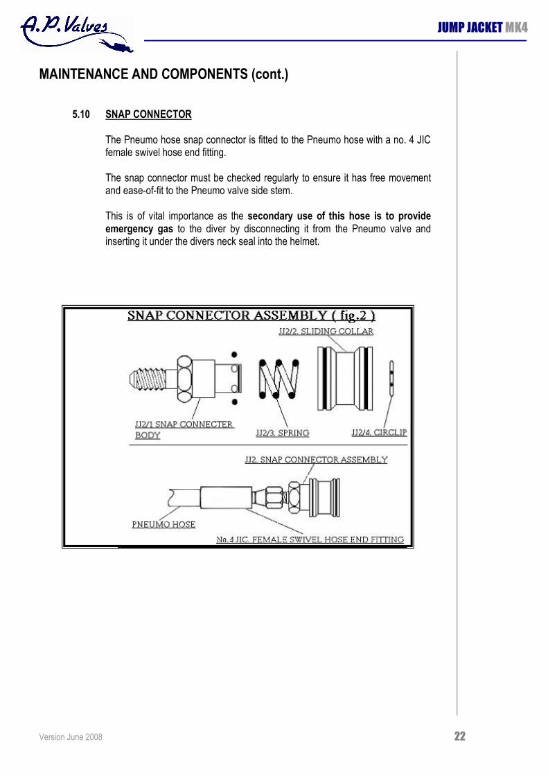
5.11 CAM BUCKLE (CYLINDER QUICK RELEASE)

Version June 2008 24
JUMP JACKET MK4
PART NUMBERS
JACKET SPARES
AP6. EMERGENCY 0.4 LT. CYLINDER AP8P PILLAR VALVE (TO FIT AP6 CYLINDER) AP35A CYLINDER POST JJH1 HARNESS BK6 BACK PLATE AP26N/04 INNER BLADDER JJ21 TOOL BAG
CYLINDER FITTING KITS
BK15 5.5" (140MM.) DIA. CYLINDER
BK16 7" (178MM.) DIA. CYLINDER
BK17 8" (203MM.) DIA. CYLINDER
DUMP VALVE
AP5 DUMP VALVE COMPLETE AP15A DUMP VALVE PROTECTOR AP5JJ DUMP VALVE TOP COVER WITH GRIT FILTER AP5B DUMP VALVE CORD
JJ1 PNEUMO VALVE (pre 1999)
JJ1 PNEUMO VALVE COMPLETE JJ1/1 VALVE BODY 4BA SCREW, COUNTERSUNK (STAINLESS) JJ1/2 BUTTON RETAINING RING JJ1/3 INFLATOR BUTTON JJ1/4 SIDE STEM JJ1/5 VALVE SPRING AP100/41 FILTER AP100/21JJ FILTER RETAINING RING AP15 PROTECTOR AP4B VALVE RETAINING COLLAR BS.012 70SH ORING
Version June 2008 25
JUMP JACKET MK4
PART NUMBERS (cont.)
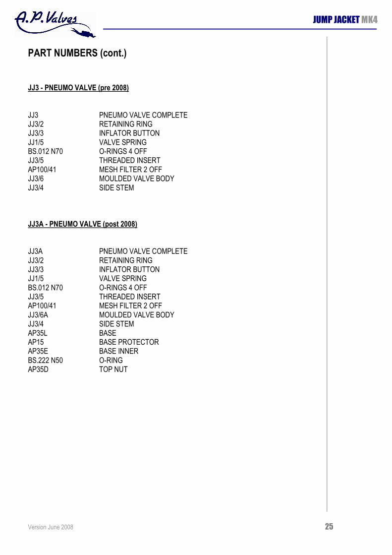
JJ3 PNEUMO VALVE (pre 2008)
JJ3 PNEUMO VALVE COMPLETE JJ3/2 RETAINING RING JJ3/3 INFLATOR BUTTON JJ1/5 VALVE SPRING BS.012 N70 ORINGS 4 OFF JJ3/5 THREADED INSERT AP100/41 MESH FILTER 2 OFF JJ3/6 MOULDED VALVE BODY JJ3/4 SIDE STEM
JJ3A PNEUMO VALVE (post 2008)
JJ3A PNEUMO VALVE COMPLETE JJ3/2 RETAINING RING JJ3/3 INFLATOR BUTTON JJ1/5 VALVE SPRING BS.012 N70 ORINGS 4 OFF JJ3/5 THREADED INSERT AP100/41 MESH FILTER 2 OFF JJ3/6A MOULDED VALVE BODY JJ3/4 SIDE STEM AP35L BASE AP15 BASE PROTECTOR AP35E BASE INNER BS.222 N50 ORING AP35D TOP NUT

Version June 2008 26
JUMP JACKET MK4
PART NUMBERS (cont.)
SNAP CONNECTOR
JJ2 SNAP CONNECTOR ASSEMBLY JJ2/1 SNAP CONNECTOR BODY JJ2/2 SLIDING COLLAR JJ2/3 SNAP CONNECTOR SPRING JJ2/4 CIRCLIP FOR SNAP CONNECTOR
MAIN SUPPLY VALVE
RB05/01 VALVE BODY STAT61 STICKER RB05/05 INSERT RB05/06 SPRING RB05/07 BUTTON AP15 PROTECTOR AP35D LOCK RING AP35E CYLINDER POST AP35L INNER LOCK RING AP400/3 SPINDLE AP400/4 FILTER BS .006N70 O RING BS .010N70 O RING 2 OFF BS .222N70 O RING

Version June 2008 27
JUMP JACKET MK4
PART NUMBERS (cont.)
SWAGELOK QUICK CONNECT FITTINGS
JJ16 MALE JJ15 FEMALE/BODY
HYDRASUN 90 ◦ SWIVEL ELBOW
JJ17 90 ◦ SWIVEL ELBOW
1.5M SUPPLY HOSE TO TAKE SWAGELOK FITTINGS
JJ14 HOSE ASSEMBLY WITH AP50P3 AND JJ12/1 FITTINGS JJ12/1 HOSE CONNECTOR AP50P3 HOSE COLLAR AP50C LP HOSE JJ20 JJ14 COMPLETE WITH JJ16 SWAGELOK MALE ENDS
SECONDARY LIFT EXTENSION
JJ19


![Mk4 Construction and Operation 3[1]](https://static.fdocuments.in/doc/165x107/577ce6451a28abf10392873a/mk4-construction-and-operation-31.jpg)