
THE JOINED WING SCALED DEMONSTRATOR RESULTS OF CFD · 2014-12-11 · XFLR5. Baseline airfoil...
9
1 Abstract The following work is a short revision of CFD analysis of unconventional aircraft configuration, that has been done in The Institute of Aviation during the contribution within MOSUPS consortium. Following article contains short description of tools used in CFD simulation, a sketch of methodology, sample of results of calculations and explanation of tendencies and influences of certain phenomena appearing on flow field. In assumption it is an example, what kind of information can be assessed using CFD tools, whichare not always from top of the shell, but are fast and reliable in given flight conditions. This work was supported by The National Centre for Research and Development under grant No. PBS/A6/14/2012 1. General Introduction The Joined Wing Concept has numerous advantages. There are two aerodynamic solutions that became crucial to create such configuration: the box wing and the staggered wings. The idea of box wing, proposed by Prandtl in 1924 [9], is based on assumption that using specific aerodynamic configuration of biplane, where upper wing and lower wing are connected at wingtip with plates, one can reduce significantly the induced drag of such aircraft. Using staggered wings, where one of the lifting surfaces in biplane configuration is moved forward, all benefits of aerodynamic interference: increased aircraft longitudinal stability, aerodynamic efficiency and maximum lift, can be also utilized. The idea of Joined Wing Concept is to move one of the wing in biplane configuration as much forward, as the horizontal stabilizer becomes unnecessary. Usually this is done that way, that one or both wings are swept. Then the induced drag is decreased by the wingtip plates. Fig. 1 The concept of joined wing demonstrator That configuration has numerous non- aerodynamic advantages: stiffness of connected wings is increased so the aircraft can be lighter or can withstand more load than the similar without wingtip connection. The wingtip connection from structural point of view causes static indeterminacy, which can be good, but causes some technological issues: the tolerances in connections have to be tighter than in classic configuration. That was the reason, that such configuration hasn’t been utilized in many designs. Another reason was aerodynamic complexity due to the close aerodynamic coupling [6]. Situation changes, when advanced computational tools become available. THE JOINED WING SCALED DEMONSTRATOR RESULTS OF CFD Adam Dziubiński*, Sara Kuprianowicz*, Katarzyna Surmacz*, Cezary Galiński*, Jerzy Żółtak* *Instytut Lotnictwa Keywords: computational aerodynamics, joined wing, simulation.
Transcript of THE JOINED WING SCALED DEMONSTRATOR RESULTS OF CFD · 2014-12-11 · XFLR5. Baseline airfoil...
1
Abstract
The following work is a short revision of CFD
analysis of unconventional aircraft
configuration, that has been done in The
Institute of Aviation during the contribution
within MOSUPS consortium. Following article
contains short description of tools used in CFD
simulation, a sketch of methodology, sample of
results of calculations and explanation of
tendencies and influences of certain phenomena
appearing on flow field. In assumption it is an
example, what kind of information can be
assessed using CFD tools, whichare not always
from top of the shell, but are fast and reliable in
given flight conditions. This work was supported
by The National Centre for Research and
Development under grant No. PBS/A6/14/2012
1. General Introduction
The Joined Wing Concept has numerous
advantages. There are two aerodynamic
solutions that became crucial to create such
configuration: the box wing and the staggered
wings. The idea of box wing, proposed by
Prandtl in 1924 [9], is based on assumption that
using specific aerodynamic configuration of
biplane, where upper wing and lower wing are
connected at wingtip with plates, one can reduce
significantly the induced drag of such aircraft.
Using staggered wings, where one of the lifting
surfaces in biplane configuration is moved
forward, all benefits of aerodynamic
interference: increased aircraft longitudinal
stability, aerodynamic efficiency and maximum
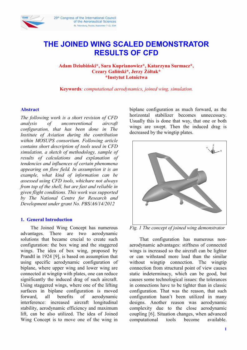
lift, can be also utilized. The idea of Joined
Wing Concept is to move one of the wing in
biplane configuration as much forward, as the
horizontal stabilizer becomes unnecessary.
Usually this is done that way, that one or both
wings are swept. Then the induced drag is
decreased by the wingtip plates.
Fig. 1 The concept of joined wing demonstrator
That configuration has numerous non-
aerodynamic advantages: stiffness of connected
wings is increased so the aircraft can be lighter
or can withstand more load than the similar
without wingtip connection. The wingtip
connection from structural point of view causes
static indeterminacy, which can be good, but
causes some technological issues: the tolerances
in connections have to be tighter than in classic
configuration. That was the reason, that such
configuration hasn’t been utilized in many
designs. Another reason was aerodynamic
complexity due to the close aerodynamic
coupling [6]. Situation changes, when advanced
computational tools become available.
THE JOINED WING SCALED DEMONSTRATOR RESULTS OF CFD
Adam Dziubiński*, Sara Kuprianowicz*, Katarzyna Surmacz*,
Cezary Galiński*, Jerzy Żółtak*
*Instytut Lotnictwa
Keywords: computational aerodynamics, joined wing, simulation.

Adam Dziubiński, Sara Kuprianowicz, Katarzyna Surmacz, Cezary Galiński, Jerzy Żółtak
2
Designers now have opportunity to use both
CFD and FEM tools in process of multicriterial
design. As new configuration is available, new
aerodynamic issues and uncertainties appear,
which also can be determined and solved using
CFD tools [3]. The presented paper concerns
about influence of selected design solutions on
aerodynamic characteristics of joined wing
configuration aircraft.
The Joined Wing Scaled Demonstrator
Program (MOSUPS), is a consortium created to
explore advantages of joined wing concept, and
The Institute of Aviation is a main contributor.
At actual stage, configuration of demonstrator is
chosen as a joined wing with positive stagger
(upper wing in front of the center of gravity,
lower at the back). Front wing and wingtip
plates are swept backward. The aircraft is
designed in pusher configuration with ducted
fan, and has a front-wheel type of landing gear.
This configuration is an effect of research and
experience achieved on previous designs created
in Warsaw University of Technology [8].
2. Analysis
In CFD analysis done in The Institute of
Aviation, a set of geometrical features has been
considered to obtain their influence on
aerodynamic characteristics. Since the wing
configuration and surfaces has been defined by
Warsaw University of Technology, our set has
been defined as follows: airfoils and twist
angles of both wings: front and rear, shape of a
fuselage, fillets between fuselage and wings,
shape of wingtip plates, influence of landing
gear, influence of connection between rear
wing, fuselage, and propeller duct. Shape of
centerbody (engine cover including propeller
spinner) and its influence on separation inside
the propeller duct has also been considered.
Almost all configurations have been tested to
obtain working propeller influence. In general
this information caused the designers to choose
which modifications are necessary, and which
are to be neglected in future works. Some
elements, as for example the connection
between duct wing and fuselage, has been
chosen to be tested in wind tunnel and on flying
model as one of the switchable modules.
Usually those elements are worth considering, if
their positive influence is not neglected by their
mass. Also a lot of uncertainties can be
understood and solved only after experimental
test. Later on both CFD analyses results and
wind tunnel tests are used to simulate behavior
of an airplane as shown in [7] with methods
presented in [4,5].
CFD simulations have been done using two
tools: XFLR5 and ANSYS Fluent. A freeware
XFLR5 software, an implementation of widely
recognized XFOIL created by M. Drela [2] to
analyze one-element airfoils, but its abilities
have been extended to use lifting line theory and
also vortex lattice and panel method to analyze
wings and whole airframe configurations (Fig.
2) in static conditions and in obtaining stability
data.
Fig. 2 XFLR5 screenshots (model and sample
result) of twist angle analysis for
simplified box wing configuration
XFLR5 to analyze a 2D airfoil uses a
potential panel method with influence of
boundary layer thickness. Turbulisation and
separation are taken into account using
secondary panel set, which are moved away
from airfoil surface by the offset equal to
boundary layer thickness in this area.
3
THE JOINED WING SCALED DEMONSTRATOR RESULTS OF CFD ANALYSIS
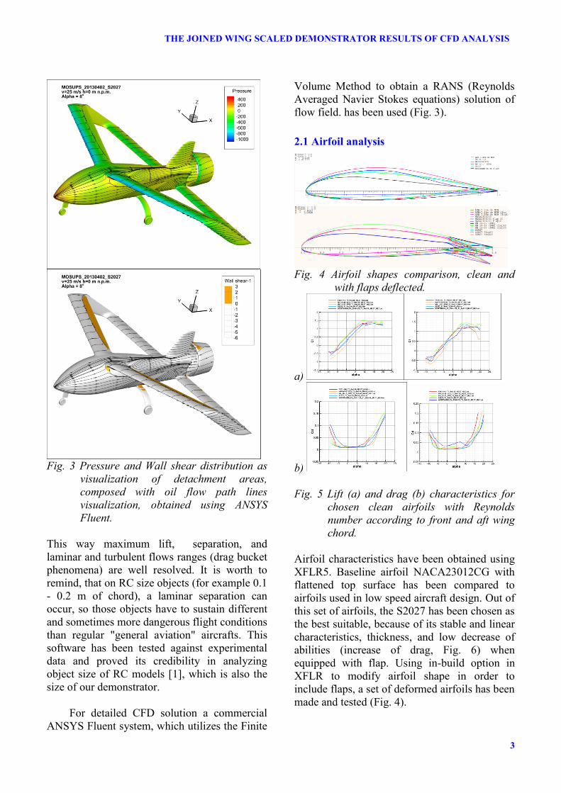
Fig. 3 Pressure and Wall shear distribution as
visualization of detachment areas,
composed with oil flow path lines
visualization, obtained using ANSYS
Fluent.
This way maximum lift, separation, and
laminar and turbulent flows ranges (drag bucket
phenomena) are well resolved. It is worth to
remind, that on RC size objects (for example 0.1
- 0.2 m of chord), a laminar separation can
occur, so those objects have to sustain different
and sometimes more dangerous flight conditions
than regular "general aviation" aircrafts. This
software has been tested against experimental
data and proved its credibility in analyzing
object size of RC models [1], which is also the
size of our demonstrator.
For detailed CFD solution a commercial
ANSYS Fluent system, which utilizes the Finite
Volume Method to obtain a RANS (Reynolds
Averaged Navier Stokes equations) solution of
flow field. has been used (Fig. 3).
2.1 Airfoil analysis
Fig. 4 Airfoil shapes comparison, clean and
with flaps deflected.
a)
b)
Fig. 5 Lift (a) and drag (b) characteristics for
chosen clean airfoils with Reynolds
number according to front and aft wing
chord.
Airfoil characteristics have been obtained using
XFLR5. Baseline airfoil NACA23012CG with
flattened top surface has been compared to
airfoils used in low speed aircraft design. Out of
this set of airfoils, the S2027 has been chosen as
the best suitable, because of its stable and linear
characteristics, thickness, and low decrease of
abilities (increase of drag, Fig. 6) when
equipped with flap. Using in-build option in
XFLR to modify airfoil shape in order to
include flaps, a set of deformed airfoils has been
made and tested (Fig. 4).

8TH
INTERNATIONAL SYMPOSIUM ON FLOW VISUALIZATION (1998)
-Błąd! Tylko dokument główny
Fig. 6 Comparison of draglift moment and lift over drag characteristics between baseline and chosen
airfoil for three different flap deflections.
a)
b)
c)
Fig. 7 a) size of mesh around an airplane, b)density distribution of mesh around ducted fan and c)
ducted fan with surface of symmetry and actuator disc. On both surfaces the size of boundary layer
mesh is visible.

5
THE JOINED WING SCALED DEMONSTRATOR RESULTS OF CFD ANALYSIS
Fig. 1 Comparison between longitudal aerodynamic characteristics for different extension of the
elevon and elevator.
2.2 Control surfaces effectiveness
In order to verify the control surfaces
effectiveness, comercial RANS CFD solver
using Spalart - Allmaras turbulence model has
been used as it is usually recommended for
external flow cases. 1.5 million elements
tetrahedral grid (fig. 7a) has been created to
model half of the aircraft (symmetry of
geometry and flowfield has been assumed) .
Around the model a few layers of hexahedral
mesh have been created to properly obtain the
influence of a boundary layer in terms of
separation (fig. 7c).
The propeller influence has been modeled
with actuator disc (constant pressure jump
surface). All configurations have been tested in
range of angle of attack between -10° and 20°,
for assumed cruise velocity of 25 m/s. The
model has been divided into functional parts
(for example: fuselage, landing gear, front
wing). The results obtained for whole range of
angle of attack, could be presented for chosen
elements or features as divided into parts. It
provides useful information on aerodynamic
interference of selected parts on each other, and
ranges of angles of attack where this influence
occurs.
In fig. 8 the qualitative results for different
extension of elevator and influence of equal
extension of elevon has been shown. On fig.9
and 10 respectively the separation areas and
pressure distribution over the wings has been
shown. The separation areas are simply
distributions of shear stress component in
flightwise direction. If the shear force is
negative, that means flow is against the flight
velocity, so the separation most probably
occurred. This method of course fails, when the
negative flow appears from the other reasons
than the flow detachment. For example at
stagnation area at the high angle of attack, when
the part of air near nose of airfoil flows against
the flight direction. But one could easily filter
out those areas knowing where to find them.
For each combination of extension a different
mesh has been created (Fig. 10). This approach
has been used because of best quality of mesh
and little if any complication for those cases in
comparison to moving/deflecting mesh
approach.

Adam Dziubiński, Sara Kuprianowicz, Katarzyna Surmacz, Cezary Galiński, Jerzy Żółtak
6
Fig. 10 Separation areas and pressure distribution for both elevon and elevator extended equally.
8TH
INTERNATIONAL SYMPOSIUM ON FLOW VISUALIZATION (1998)
-Błąd! Tylko dokument główny
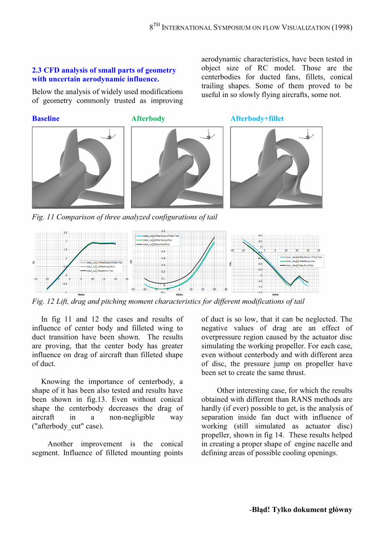
2.3 CFD analysis of small parts of geometry
with uncertain aerodynamic influence.
Below the analysis of widely used modifications
of geometry commonly trusted as improving
aerodynamic characteristics, have been tested in
object size of RC model. Those are the
centerbodies for ducted fans, fillets, conical
trailing shapes. Some of them proved to be
useful in so slowly flying aircrafts, some not.
Baseline
Afterbody
Afterbody+fillet
Fig. 11 Comparison of three analyzed configurations of tail
Fig. 12 Lift, drag and pitching moment characteristics for different modifications of tail
In fig 11 and 12 the cases and results of
influence of center body and filleted wing to
duct transition have been shown. The results
are proving, that the center body has greater
influence on drag of aircraft than filleted shape
of duct.
Knowing the importance of centerbody, a
shape of it has been also tested and results have
been shown in fig.13. Even without conical
shape the centerbody decreases the drag of
aircraft in a non-negligible way
("afterbody_cut" case).
Another improvement is the conical
segment. Influence of filleted mounting points
of duct is so low, that it can be neglected. The
negative values of drag are an effect of
overpressure region caused by the actuator disc
simulating the working propeller. For each case,
even without centerbody and with different area
of disc, the pressure jump on propeller have
been set to create the same thrust.
Other interesting case, for which the results
obtained with different than RANS methods are
hardly (if ever) possible to get, is the analysis of
separation inside fan duct with influence of
working (still simulated as actuator disc)
propeller, shown in fig 14. These results helped
in creating a proper shape of engine nacelle and
defining areas of possible cooling openings.

Adam Dziubiński, Sara Kuprianowicz, Katarzyna Surmacz, Cezary Galiński, Jerzy Żółtak
8
Fig. 13 Center body shape and fillets influence on aerodynamic drag of whole aircraft.
Fig. 14 Increase of separation area size on
internal surface of the duct and rear surface of
the engine nacelle with increase of angle of
attack. Velocity magnitude distribution with
pathlines.
3. Summary.
CFD again proved its functionality with
obtaining crucial information about small design
changes and its influence on aerodynamics
without building an expensive wind tunnel
model with many switchable modules. Great
advantage is the ability to introduce advanced
phenomena modeling at early stage of design
(for example the propeller influence), so the
design can become cheaper and more robust.
4. Acknowledgements.
This work was supported by The National
Centre for Research and Development under
grant No. PBS/A6/14/2012”
5. References.
[1] Deperrois A, About XFLR5 calculations and
experimental measurements Rev1.1 (2009),
www.xflr5.com [2] Drela M, XFOIL: An Analysis and Design System
for Low Reynolds Number Airfoils, Low Reynolds
Number Aerodynamics Proceedings of the
Conference, Notre Dame, Indiana, USA, 1989.
[3] Galiński C, Hajduk J, Kalinowski M, Wichulski M,
Stefanek Ł, Inverted Joined Wing Scaled
Demonstrator Programme, Proceedings of the
ICAS’2014 conference, ICAS, Petersburg, Russia,
2014, ICAS2014-1.10ST, in print
[4] Goetzendorf-Grabowski T, Mieszalski D,
Marcinkiewicz E.; Stability analysis using SDSA
tool, Progress in Aerospace Sciences, Vol: 47 Issue:
8 Special Issue: SI pp. 636-646 Published: NOV
2011
[5] Goraj Z, Flight dynamics models used in different
national and international projects Aircraft
Engineering and Aerospace Technology, Volume
86, issue 3, 2014, pp.166-178

9
THE JOINED WING SCALED DEMONSTRATOR RESULTS OF CFD ANALYSIS
[6] Goraj Z, Kulicki P, Lasek M, Aircraft Stability
Analysis For Strongly Coupled Aerodynamic
Configuration, Journal of Theoretical and Applied
Mechanics, Vol. 35, No. 1, 1997, pp.137-158.
[7] Lis M, Dziubiński A, Galiński C, Krysztofiak G,
Ruchała P, Surmacz K, Predicted Flight
Characteristics of the Inverted Joined Wing Scaled
Demonstrator, Proceedings of the ICAS’2014
conference, ICAS, Petersburg, Russia, 2014,
ICAS2014-P2.4.13, in print
[8] Mamla P, Galinski C, Basic Induced Drag Study of
the Joined-Wing Aircraft, Journal of Aircraft, Vol.
46, No. 4, 2009, pp. 1438-1440. [9] Prandtl L, Induced drag of multiplanes NACA TN
182, 1924.
6. Contact Author Email Address
mailto: [email protected]
Copyright Statement
The authors confirm that they, and/or their company or
organization, hold copyright on all of the original material
included in this paper. The authors also confirm that they
have obtained permission, from the copyright holder of
any third party material included in this paper, to publish
it as part of their paper. The authors confirm that they
give permission, or have obtained permission from the
copyright holder of this paper, for the publication and
distribution of this paper as part of the ICAS 2014
proceedings or as individual off-prints from the
proceedings.


![Blended Wing’ CFD Analysis: Aerodynamic Coefficients. · airfoils at low Reynolds numbers, such as the XFLR5 [5, 7]. Nevertheless, the values obtained through this software are](https://static.fdocuments.in/doc/165x107/5e68547c68b2a32bb7246be4/blended-winga-cfd-analysis-aerodynamic-airfoils-at-low-reynolds-numbers-such.jpg)