![TEE Sockets API Specification v1.0 - GlobalPlatform · TEE Sockets API Specification Annex A: TCP/IP Specification of TEE Sockets API Specification [Sockets TCP/IP] GPD_SPE_102 :](https://static.fdocuments.in/doc/165x107/60421070f2b21560856dea9a/tee-sockets-api-specification-v10-globalplatform-tee-sockets-api-specification.jpg)
The Java 3D API Specification - Oracle Specification Version 1.2, April 2000 ... 4.6 API for...
664
The Java 3D ™ API Specification Version 1.2, April 2000 901 San Antonio Road Palo Alto, CA 94303 USA 415 960-1300 fax 415 969-9131 A Sun Microsystems, Inc. Business JavaSoft
-
Upload
nguyenthien -
Category
Documents
-
view
224 -
download
1
Transcript of The Java 3D API Specification - Oracle Specification Version 1.2, April 2000 ... 4.6 API for...

The Java 3D™
API Specification
Version 1.2, April 2000
901 San Antonio RoadPalo Alto, CA 94303 USA415 960-1300 fax 415 969-9131
A Sun Microsystems, Inc. Business
JavaSoft

1997, 1998, 1999, 2000 Sun Microsystems, Inc.901 San Antonio Road, Palo Alto, California 94303 U.S.A.All rights reserved.
RESTRICTED RIGHTS LEGEND: Use, duplication, or disclosure by the United StatesGovernment is subject to the restrictions set forth in DFARS 252.227-7013 (c)(1)(ii) andFAR 52.227-19.
The release described in this document may be protected by one or more U.S. patents, for-eign patents, or pending applications.
Sun Microsystems, Inc. (SUN) hereby grants to you a fully paid, nonexclusive, nontrans-ferable, perpetual, worldwide limited license (without the right to sublicense) underSUN’s intellectual property rights that are essential to practice this specification. Thislicense allows and is limited to the creation and distribution of clean-room implementa-tions of this specification that (i) are complete implementations of this specification, (ii)pass all test suites relating to this specification that are available from SUN, (iii) do notderive from SUN source code or binary materials, and (iv) do not include any SUN binarymaterials without an appropriate and separate license from SUN.
Java, JavaScript, and Java 3D are trademarks of Sun Microsystems, Inc. Sun, Sun Micro-systems, the Sun logo, Java, and HotJava are trademarks or registered trademarks of SunMicrosystems, Inc. UNIX® is a registered trademark in the United States and other coun-tries, exclusively licensed through X/Open Company, Ltd. All other product names men-tioned herein are the trademarks of their respective owners.
THIS PUBLICATION IS PROVIDED “AS IS” WITHOUT WARRANTY OF ANYKIND, EITHER EXPRESS OR IMPLIED, INCLUDING, BUT NOT LIMITED TO, THEIMPLIED WARRANTIES OF MERCHANTABILITY, FITNESS FOR A PARTICULARPURPOSE, OR NON-INFRINGEMENT.
THIS PUBLICATION COULD INCLUDE TECHNICAL INACCURACIES OR TYPO-GRAPHICAL ERRORS. CHANGES ARE PERIODICALLY ADDED TO THE INFOR-MATION HEREIN; THESE CHANGES WILL BE INCORPORATED IN NEWEDITIONS OF THE PUBLICATION. SUN MICROSYSTEMS, INC. MAY MAKEIMPROVEMENTS AND/OR CHANGES IN THE PRODUCT(S) AND/OR THE PRO-GRAM(S) DESCRIBED IN THIS PUBLICATION AT ANY TIME.
. xv
xvii
1. . .1 . .2 .2. .2.3 . .4 .4 .5 .5. .5. .6. .6 . .6 .6. .8 .9
11. .11.12.125 .15. .16.16.1717
19. .19.19
Contents
Figures . . . . . . . . . . . . . . . . . . . . . . . . . . . . . . . . . . . . . . . . . . . . . . . . .
Preface . . . . . . . . . . . . . . . . . . . . . . . . . . . . . . . . . . . . . . . . . . . . . . . . .
1 Introduction to Java 3D . . . . . . . . . . . . . . . . . . . . . . . . . . . . . . . . . .1.1 Goals . . . . . . . . . . . . . . . . . . . . . . . . . . . . . . . . . . . . . . . . . . . . . . . . . 1.2 Programming Paradigm. . . . . . . . . . . . . . . . . . . . . . . . . . . . . . . . . . . .
1.2.1 The Scene Graph Programming Model . . . . . . . . . . . . . .1.2.2 Rendering Modes . . . . . . . . . . . . . . . . . . . . . . . . . . . . . . 1.2.3 Extensibility . . . . . . . . . . . . . . . . . . . . . . . . . . . . . . . . . . .
1.3 High Performance . . . . . . . . . . . . . . . . . . . . . . . . . . . . . . . . . . . . . . . .1.3.1 Layered Implementation. . . . . . . . . . . . . . . . . . . . . . . . . .1.3.2 Target Hardware Platforms . . . . . . . . . . . . . . . . . . . . . . .
1.4 Support for Building Applications and Applets . . . . . . . . . . . . . . . . . .1.4.1 Browsers . . . . . . . . . . . . . . . . . . . . . . . . . . . . . . . . . . . . . 1.4.2 Games . . . . . . . . . . . . . . . . . . . . . . . . . . . . . . . . . . . . . . .
1.5 Overview of Java 3D Object Hierarchy. . . . . . . . . . . . . . . . . . . . . . . . 1.6 Structuring the Java 3D Program. . . . . . . . . . . . . . . . . . . . . . . . . . . . .
1.6.1 Java 3D Application Scene Graph . . . . . . . . . . . . . . . . . .1.6.2 Recipe for a Java 3D Program . . . . . . . . . . . . . . . . . . . . 1.6.3 HelloUniverse: A Sample Java 3D Program . . . . . . . . . .
2 Java 3D Concepts . . . . . . . . . . . . . . . . . . . . . . . . . . . . . . . . . . . . . .2.1 Basic Scene Graph Concepts . . . . . . . . . . . . . . . . . . . . . . . . . . . . . . .
2.1.1 Constructing a Simple Scene Graph. . . . . . . . . . . . . . . . 2.1.2 A Place For Scene Graphs . . . . . . . . . . . . . . . . . . . . . . . 2.1.3 SimpleUniverse Utility . . . . . . . . . . . . . . . . . . . . . . . . . . .12.1.4 Processing a Scene Graph. . . . . . . . . . . . . . . . . . . . . . . .
2.2 Features of Java 3D . . . . . . . . . . . . . . . . . . . . . . . . . . . . . . . . . . . . . . 2.2.1 Bounds . . . . . . . . . . . . . . . . . . . . . . . . . . . . . . . . . . . . . . 2.2.2 Nodes . . . . . . . . . . . . . . . . . . . . . . . . . . . . . . . . . . . . . . . 2.2.3 Live and/or Compiled. . . . . . . . . . . . . . . . . . . . . . . . . . . .
3 Scene Graph Basics. . . . . . . . . . . . . . . . . . . . . . . . . . . . . . . . . . . . .3.1 Scene Graph Structure . . . . . . . . . . . . . . . . . . . . . . . . . . . . . . . . . . . .
3.1.1 Spatial Separation. . . . . . . . . . . . . . . . . . . . . . . . . . . . . .
iiiVersion 1.2, April 2000
CONTENTS
iv
2021 . 212326 . 277
27. 272828
282828
3131
. 3233
. 3333
3344366
3738
41. 41. 44. 45. 47. 47. 48 . 50
51. 51 . 515558
. 59. 6163
. 6668
3.1.2 State Inheritance . . . . . . . . . . . . . . . . . . . . . . . . . . . . . . .3.1.3 Rendering . . . . . . . . . . . . . . . . . . . . . . . . . . . . . . . . . . . .
3.2 Scene Graph Objects . . . . . . . . . . . . . . . . . . . . . . . . . . . . . . . . . . . . .3.2.1 Node Objects . . . . . . . . . . . . . . . . . . . . . . . . . . . . . . . . . .3.2.2 NodeComponent Objects . . . . . . . . . . . . . . . . . . . . . . . .
3.3 Scene Graph Superstructure Objects . . . . . . . . . . . . . . . . . . . . . . . . .3.3.1 VirtualUniverse Object . . . . . . . . . . . . . . . . . . . . . . . . . . 23.3.2 Locale Object . . . . . . . . . . . . . . . . . . . . . . . . . . . . . . . . .
3.4 Scene Graph Viewing Objects . . . . . . . . . . . . . . . . . . . . . . . . . . . . . . 3.4.1 Canvas3D Object. . . . . . . . . . . . . . . . . . . . . . . . . . . . . . .3.4.2 Screen3D Object . . . . . . . . . . . . . . . . . . . . . . . . . . . . . . .3.4.3 View Object. . . . . . . . . . . . . . . . . . . . . . . . . . . . . . . . . . .3.4.4 PhysicalBody Object . . . . . . . . . . . . . . . . . . . . . . . . . . . .3.4.5 PhysicalEnvironment Object. . . . . . . . . . . . . . . . . . . . . .
4 Scene Graph Superstructure . . . . . . . . . . . . . . . . . . . . . . . . . . . . .4.1 The Virtual Universe . . . . . . . . . . . . . . . . . . . . . . . . . . . . . . . . . . . . . .4.2 Establishing a Scene. . . . . . . . . . . . . . . . . . . . . . . . . . . . . . . . . . . . . .4.3 Loading a Virtual Universe . . . . . . . . . . . . . . . . . . . . . . . . . . . . . . . . .4.4 Coordinate Systems . . . . . . . . . . . . . . . . . . . . . . . . . . . . . . . . . . . . . .4.5 High-Resolution Coordinates . . . . . . . . . . . . . . . . . . . . . . . . . . . . . . . .
4.5.1 Java 3D High-Resolution Coordinates . . . . . . . . . . . . . .4.5.2 Java 3D Virtual World Coordinates . . . . . . . . . . . . . . . . 34.5.3 Details of High-Resolution Coordinates . . . . . . . . . . . . . 3
4.6 API for Superstructure Objects . . . . . . . . . . . . . . . . . . . . . . . . . . . . . .4.6.1 VirtualUniverse Object . . . . . . . . . . . . . . . . . . . . . . . . . . 34.6.2 Locale Object . . . . . . . . . . . . . . . . . . . . . . . . . . . . . . . . .4.6.3 HiResCoord Object . . . . . . . . . . . . . . . . . . . . . . . . . . . . .
5 Group Node Objects . . . . . . . . . . . . . . . . . . . . . . . . . . . . . . . . . . . .5.1 Group Node . . . . . . . . . . . . . . . . . . . . . . . . . . . . . . . . . . . . . . . . . . . . 5.2 BranchGroup Node. . . . . . . . . . . . . . . . . . . . . . . . . . . . . . . . . . . . . . . 5.3 TransformGroup Node . . . . . . . . . . . . . . . . . . . . . . . . . . . . . . . . . . . . 5.4 OrderedGroup Node . . . . . . . . . . . . . . . . . . . . . . . . . . . . . . . . . . . . . . 5.5 DecalGroup Node. . . . . . . . . . . . . . . . . . . . . . . . . . . . . . . . . . . . . . . . 5.6 Switch Node . . . . . . . . . . . . . . . . . . . . . . . . . . . . . . . . . . . . . . . . . . . . 5.7 SharedGroup Node . . . . . . . . . . . . . . . . . . . . . . . . . . . . . . . . . . . . . . .
6 Leaf Node Objects . . . . . . . . . . . . . . . . . . . . . . . . . . . . . . . . . . . . . .6.1 Leaf Node . . . . . . . . . . . . . . . . . . . . . . . . . . . . . . . . . . . . . . . . . . . . . . 6.2 Shape3D Node . . . . . . . . . . . . . . . . . . . . . . . . . . . . . . . . . . . . . . . . . .
6.2.1 OrientedShape3D Node. . . . . . . . . . . . . . . . . . . . . . . . . .6.3 BoundingLeaf Node . . . . . . . . . . . . . . . . . . . . . . . . . . . . . . . . . . . . . . .6.4 Background Node. . . . . . . . . . . . . . . . . . . . . . . . . . . . . . . . . . . . . . . . 6.5 Clip Node . . . . . . . . . . . . . . . . . . . . . . . . . . . . . . . . . . . . . . . . . . . . . . 6.6 ModelClip Node . . . . . . . . . . . . . . . . . . . . . . . . . . . . . . . . . . . . . . . . . .6.7 Fog Node . . . . . . . . . . . . . . . . . . . . . . . . . . . . . . . . . . . . . . . . . . . . . .
6.7.1 ExponentialFog Node . . . . . . . . . . . . . . . . . . . . . . . . . . .
The Java 3D API Specification
69 .7133
7476. .77.84.84.88 . .95.97 .99 .99102.102
105.10505
0710809
11013
1141515
19119191935
2728303336384045454649512
6.7.2 LinearFog Node . . . . . . . . . . . . . . . . . . . . . . . . . . . . . . . .6.8 Light Node. . . . . . . . . . . . . . . . . . . . . . . . . . . . . . . . . . . . . . . . . . . . . .
6.8.1 AmbientLight Node . . . . . . . . . . . . . . . . . . . . . . . . . . . . .76.8.2 DirectionalLight Node . . . . . . . . . . . . . . . . . . . . . . . . . . .76.8.3 PointLight Node . . . . . . . . . . . . . . . . . . . . . . . . . . . . . . . .6.8.4 SpotLight Node. . . . . . . . . . . . . . . . . . . . . . . . . . . . . . . . .
6.9 Sound Node . . . . . . . . . . . . . . . . . . . . . . . . . . . . . . . . . . . . . . . . . . . . 6.9.1 BackgroundSound Node. . . . . . . . . . . . . . . . . . . . . . . . . 6.9.2 PointSound Node . . . . . . . . . . . . . . . . . . . . . . . . . . . . . . 6.9.3 ConeSound Node . . . . . . . . . . . . . . . . . . . . . . . . . . . . . .
6.10 Soundscape Node. . . . . . . . . . . . . . . . . . . . . . . . . . . . . . . . . . . . . . . .6.11 ViewPlatform Node. . . . . . . . . . . . . . . . . . . . . . . . . . . . . . . . . . . . . . . 6.12 Behavior Node. . . . . . . . . . . . . . . . . . . . . . . . . . . . . . . . . . . . . . . . . . .6.13 Morph Node. . . . . . . . . . . . . . . . . . . . . . . . . . . . . . . . . . . . . . . . . . . . .6.14 Link Node . . . . . . . . . . . . . . . . . . . . . . . . . . . . . . . . . . . . . . . . . . . . . .6.15 AlternateAppearance Node . . . . . . . . . . . . . . . . . . . . . . . . . . . . . . . .
7 Reusing Scene Graphs . . . . . . . . . . . . . . . . . . . . . . . . . . . . . . . . .7.1 Sharing Subgraphs. . . . . . . . . . . . . . . . . . . . . . . . . . . . . . . . . . . . . . .
7.1.1 SharedGroup Node . . . . . . . . . . . . . . . . . . . . . . . . . . . . .17.1.2 Link Leaf Node. . . . . . . . . . . . . . . . . . . . . . . . . . . . . . . .1
7.2 Cloning Subgraphs. . . . . . . . . . . . . . . . . . . . . . . . . . . . . . . . . . . . . . . .7.2.1 References to Node Component Objects . . . . . . . . . . . .17.2.2 References to Other Scene Graph Nodes . . . . . . . . . . . .7.2.3 Dangling References. . . . . . . . . . . . . . . . . . . . . . . . . . . .17.2.4 Subclassing Nodes . . . . . . . . . . . . . . . . . . . . . . . . . . . . .7.2.5 NodeReferenceTable Object. . . . . . . . . . . . . . . . . . . . . .17.2.6 Example User Behavior Node . . . . . . . . . . . . . . . . . . . .1
8 Node Component Objects. . . . . . . . . . . . . . . . . . . . . . . . . . . . . . . 18.1 Node Component Objects: Attributes . . . . . . . . . . . . . . . . . . . . . . . . .
8.1.1 Alpha Object. . . . . . . . . . . . . . . . . . . . . . . . . . . . . . . . . .18.1.2 Appearance Object . . . . . . . . . . . . . . . . . . . . . . . . . . . . .18.1.3 ColoringAttributes Object . . . . . . . . . . . . . . . . . . . . . . .128.1.4 LineAttributes Object . . . . . . . . . . . . . . . . . . . . . . . . . . .128.1.5 PointAttributes Object . . . . . . . . . . . . . . . . . . . . . . . . . .18.1.6 PolygonAttributes Object . . . . . . . . . . . . . . . . . . . . . . . .18.1.7 RenderingAttributes Object . . . . . . . . . . . . . . . . . . . . . .18.1.8 TextureAttributes Object . . . . . . . . . . . . . . . . . . . . . . . .18.1.9 TransparencyAttributes Object. . . . . . . . . . . . . . . . . . . .18.1.10 Material Object . . . . . . . . . . . . . . . . . . . . . . . . . . . . . . . .18.1.11 Texture Object . . . . . . . . . . . . . . . . . . . . . . . . . . . . . . . .18.1.12 Texture2D Object . . . . . . . . . . . . . . . . . . . . . . . . . . . . . .18.1.13 Texture3D Object . . . . . . . . . . . . . . . . . . . . . . . . . . . . . .18.1.14 TexCoordGeneration Object. . . . . . . . . . . . . . . . . . . . . .18.1.15 TextureUnitState Object . . . . . . . . . . . . . . . . . . . . . . . . .18.1.16 MediaContainer Object. . . . . . . . . . . . . . . . . . . . . . . . . .18.1.17 AuralAttributes Object . . . . . . . . . . . . . . . . . . . . . . . . . .15
vVersion 1.2, April 2000
CONTENTS
vi
59626466676768687072747719091060677
08890
101114141515678
1819
222232627282323234
352366
2377
37
8.1.18 ImageComponent Object. . . . . . . . . . . . . . . . . . . . . . . . 18.1.19 ImageComponent2D Object . . . . . . . . . . . . . . . . . . . . . 18.1.20 ImageComponent3D Object . . . . . . . . . . . . . . . . . . . . . 18.1.21 DepthComponent Object. . . . . . . . . . . . . . . . . . . . . . . . 18.1.22 DepthComponentFloat Object. . . . . . . . . . . . . . . . . . . . 18.1.23 DepthComponentInt Object . . . . . . . . . . . . . . . . . . . . . 18.1.24 DepthComponentNative Object . . . . . . . . . . . . . . . . . . 18.1.25 Bounds Object . . . . . . . . . . . . . . . . . . . . . . . . . . . . . . . . 18.1.26 BoundingBox Object. . . . . . . . . . . . . . . . . . . . . . . . . . . 18.1.27 BoundingSphere Object . . . . . . . . . . . . . . . . . . . . . . . . 18.1.28 BoundingPolytope Object . . . . . . . . . . . . . . . . . . . . . . . 18.1.29 Transform3D Object . . . . . . . . . . . . . . . . . . . . . . . . . . . 1
8.2 Node Component Objects: Geometry . . . . . . . . . . . . . . . . . . . . . . . .8.2.1 GeometryArray Object . . . . . . . . . . . . . . . . . . . . . . . . . 18.2.2 GeometryUpdater Interface. . . . . . . . . . . . . . . . . . . . . . 28.2.3 PointArray Object . . . . . . . . . . . . . . . . . . . . . . . . . . . . . 28.2.4 LineArray Object. . . . . . . . . . . . . . . . . . . . . . . . . . . . . . 208.2.5 TriangleArray Object . . . . . . . . . . . . . . . . . . . . . . . . . . 208.2.6 QuadArray Object . . . . . . . . . . . . . . . . . . . . . . . . . . . . . 28.2.7 GeometryStripArray Object . . . . . . . . . . . . . . . . . . . . . 208.2.8 LineStripArray Object. . . . . . . . . . . . . . . . . . . . . . . . . . 208.2.9 TriangleStripArray Object. . . . . . . . . . . . . . . . . . . . . . . 218.2.10 TriangleFanArray Object . . . . . . . . . . . . . . . . . . . . . . . 28.2.11 IndexedGeometryArray Object . . . . . . . . . . . . . . . . . . . 28.2.12 IndexedPointArray Object. . . . . . . . . . . . . . . . . . . . . . . 28.2.13 IndexedLineArray Object . . . . . . . . . . . . . . . . . . . . . . . 28.2.14 IndexedTriangleArray Object . . . . . . . . . . . . . . . . . . . . 28.2.15 IndexedQuadArray Object . . . . . . . . . . . . . . . . . . . . . . 28.2.16 IndexedGeometryStripArray Object . . . . . . . . . . . . . . . 218.2.17 IndexedLineStripArray Object . . . . . . . . . . . . . . . . . . . 218.2.18 IndexedTriangleStripArray Object . . . . . . . . . . . . . . . . 218.2.19 IndexedTriangleFanArray Object . . . . . . . . . . . . . . . . . 28.2.20 CompressedGeometry Object . . . . . . . . . . . . . . . . . . . . 28.2.21 CompressedGeometryHeader Object . . . . . . . . . . . . . .8.2.22 Raster Object . . . . . . . . . . . . . . . . . . . . . . . . . . . . . . . . . 28.2.23 Font3D Object . . . . . . . . . . . . . . . . . . . . . . . . . . . . . . . . 28.2.24 FontExtrusion Object . . . . . . . . . . . . . . . . . . . . . . . . . . 28.2.25 Text3D Geometry Object . . . . . . . . . . . . . . . . . . . . . . . 2
8.3 Math Component Objects. . . . . . . . . . . . . . . . . . . . . . . . . . . . . . . . . .8.3.1 Tuple Objects . . . . . . . . . . . . . . . . . . . . . . . . . . . . . . . . 28.3.2 Matrix Objects. . . . . . . . . . . . . . . . . . . . . . . . . . . . . . . . 2
9 View Model. . . . . . . . . . . . . . . . . . . . . . . . . . . . . . . . . . . . . . . . . . . 29.1 Why a New Model? . . . . . . . . . . . . . . . . . . . . . . . . . . . . . . . . . . . . . .
9.1.1 The Physical Environment Influences the View . . . . . . 239.2 Separation of Physical and Virtual . . . . . . . . . . . . . . . . . . . . . . . . . . .
9.2.1 The Virtual World . . . . . . . . . . . . . . . . . . . . . . . . . . . . . 239.2.2 The Physical World . . . . . . . . . . . . . . . . . . . . . . . . . . . . 2
The Java 3D API Specification
389
041232433
454624649515153545555.25657257595926062264265
726768
69697027027071
2727274742855
898994
9596
9.3 The Objects That Define the View . . . . . . . . . . . . . . . . . . . . . . . . . . .29.4 ViewPlatform: A Place in the Virtual World . . . . . . . . . . . . . . . . . . .23
9.4.1 Moving through the Virtual World. . . . . . . . . . . . . . . . .249.4.2 Dropping in on a Favorite Place. . . . . . . . . . . . . . . . . . .29.4.3 View Attach Policy. . . . . . . . . . . . . . . . . . . . . . . . . . . . .249.4.4 Associating Geometry with a ViewPlatform . . . . . . . . .24
9.5 Generating a View . . . . . . . . . . . . . . . . . . . . . . . . . . . . . . . . . . . . . . . .9.5.1 Composing Model and Viewing Transformations . . . . .249.5.2 Multiple Locales . . . . . . . . . . . . . . . . . . . . . . . . . . . . . . .2
9.6 A Minimal Environment . . . . . . . . . . . . . . . . . . . . . . . . . . . . . . . . . . .29.7 The View Object . . . . . . . . . . . . . . . . . . . . . . . . . . . . . . . . . . . . . . . . .
9.7.1 Projection Policy. . . . . . . . . . . . . . . . . . . . . . . . . . . . . . .29.7.2 Clip Policies . . . . . . . . . . . . . . . . . . . . . . . . . . . . . . . . . .29.7.3 Projection and Clip Parameters . . . . . . . . . . . . . . . . . . .29.7.4 Frame Start Time, Duration, and Number . . . . . . . . . . .29.7.5 View Traversal and Behavior Scheduling . . . . . . . . . . .29.7.6 Scene Antialiasing . . . . . . . . . . . . . . . . . . . . . . . . . . . . .29.7.7 Depth Buffer . . . . . . . . . . . . . . . . . . . . . . . . . . . . . . . . . .2
9.8 The Screen3D Object. . . . . . . . . . . . . . . . . . . . . . . . . . . . . . . . . . . . . 9.8.1 Off-Screen Rendering. . . . . . . . . . . . . . . . . . . . . . . . . . .2
9.9 The Canvas3D Object . . . . . . . . . . . . . . . . . . . . . . . . . . . . . . . . . . . . .9.9.1 Window System–Provided Parameters . . . . . . . . . . . . .29.9.2 Off-Screen Rendering. . . . . . . . . . . . . . . . . . . . . . . . . . .29.9.3 Other Canvas3D Parameters. . . . . . . . . . . . . . . . . . . . . .9.9.4 GraphicsConfigTemplate3D Object . . . . . . . . . . . . . . . .2
9.10 The PhysicalBody Object . . . . . . . . . . . . . . . . . . . . . . . . . . . . . . . . . .9.11 The PhysicalEnvironment Object . . . . . . . . . . . . . . . . . . . . . . . . . . . .
10 Behaviors and Interpolators . . . . . . . . . . . . . . . . . . . . . . . . . . . . 2610.1 Behavior Object . . . . . . . . . . . . . . . . . . . . . . . . . . . . . . . . . . . . . . . . . .
10.1.1 Code Structure . . . . . . . . . . . . . . . . . . . . . . . . . . . . . . . .210.1.2 WakeupCondition Object . . . . . . . . . . . . . . . . . . . . . . . .210.1.3 WakeupCriterion Object. . . . . . . . . . . . . . . . . . . . . . . . .210.1.4 Composing WakeupCriterion Objects . . . . . . . . . . . . . .2
10.2 Composing Behaviors . . . . . . . . . . . . . . . . . . . . . . . . . . . . . . . . . . . . .10.3 Scheduling . . . . . . . . . . . . . . . . . . . . . . . . . . . . . . . . . . . . . . . . . . . . . .10.4 How Java 3D Performs Execution Culling . . . . . . . . . . . . . . . . . . . . .210.5 The Behavior API . . . . . . . . . . . . . . . . . . . . . . . . . . . . . . . . . . . . . . . .
10.5.1 The Behavior Node. . . . . . . . . . . . . . . . . . . . . . . . . . . . .210.5.2 WakeupCondition Object . . . . . . . . . . . . . . . . . . . . . . . .210.5.3 The WakeupCriterion Objects . . . . . . . . . . . . . . . . . . . .2
10.6 Interpolator Behaviors . . . . . . . . . . . . . . . . . . . . . . . . . . . . . . . . . . . . .10.6.1 Mapping Time to Alpha . . . . . . . . . . . . . . . . . . . . . . . . .2810.6.2 Acceleration of Alpha. . . . . . . . . . . . . . . . . . . . . . . . . . .210.6.3 The Alpha Class . . . . . . . . . . . . . . . . . . . . . . . . . . . . . . .210.6.4 The Interpolator Base Class . . . . . . . . . . . . . . . . . . . . . .210.6.5 PositionInterpolator Object. . . . . . . . . . . . . . . . . . . . . . .210.6.6 RotationInterpolator Object . . . . . . . . . . . . . . . . . . . . . .2
viiVersion 1.2, April 2000
CONTENTS
viii
9899001020305070810
101112
15315161731818
31819
322323324272828292930303131
323233
3353353636838
344
5345
10.6.7 ColorInterpolator Object . . . . . . . . . . . . . . . . . . . . . . . . 210.6.8 ScaleInterpolator Object . . . . . . . . . . . . . . . . . . . . . . . . 210.6.9 SwitchValueInterpolator Object . . . . . . . . . . . . . . . . . . 3010.6.10 TransparencyInterpolator Object. . . . . . . . . . . . . . . . . . 310.6.11 PathInterpolator Object . . . . . . . . . . . . . . . . . . . . . . . . . 310.6.12 PositionPathInterpolator Object . . . . . . . . . . . . . . . . . . 310.6.13 RotPosPathInterpolator Object . . . . . . . . . . . . . . . . . . . 310.6.14 RotPosScalePathInterpolator Object . . . . . . . . . . . . . . . 310.6.15 RotationPathInterpolator Object . . . . . . . . . . . . . . . . . . 3
10.7 Level-of-Detail Behaviors . . . . . . . . . . . . . . . . . . . . . . . . . . . . . . . . . 310.7.1 LOD Object . . . . . . . . . . . . . . . . . . . . . . . . . . . . . . . . . . 310.7.2 DistanceLOD Object . . . . . . . . . . . . . . . . . . . . . . . . . . . 3
10.8 Billboard Behavior . . . . . . . . . . . . . . . . . . . . . . . . . . . . . . . . . . . . . . . 3
11 Input Devices and Picking . . . . . . . . . . . . . . . . . . . . . . . . . . . . . . 311.1 InputDevice Interface . . . . . . . . . . . . . . . . . . . . . . . . . . . . . . . . . . . . .
11.1.1 The Abstract Interface . . . . . . . . . . . . . . . . . . . . . . . . . . 311.1.2 Instantiating and Registering a New Device . . . . . . . . . 3
11.2 Sensors . . . . . . . . . . . . . . . . . . . . . . . . . . . . . . . . . . . . . . . . . . . . . . . .11.2.1 Using and Assigning Sensors . . . . . . . . . . . . . . . . . . . . 311.2.2 Behind the (Sensor) Scenes. . . . . . . . . . . . . . . . . . . . . .11.2.3 The Sensor Object . . . . . . . . . . . . . . . . . . . . . . . . . . . . . 311.2.4 The SensorRead Object . . . . . . . . . . . . . . . . . . . . . . . . .
11.3 Picking . . . . . . . . . . . . . . . . . . . . . . . . . . . . . . . . . . . . . . . . . . . . . . . .11.3.1 SceneGraphPath Object. . . . . . . . . . . . . . . . . . . . . . . . .11.3.2 BranchGroup Node and Locale Node Pick Methods . . 311.3.3 PickShape Object . . . . . . . . . . . . . . . . . . . . . . . . . . . . . 311.3.4 PickBounds Object . . . . . . . . . . . . . . . . . . . . . . . . . . . . 311.3.5 PickPoint Object . . . . . . . . . . . . . . . . . . . . . . . . . . . . . . 311.3.6 PickRay Object . . . . . . . . . . . . . . . . . . . . . . . . . . . . . . . 311.3.7 PickSegment Object . . . . . . . . . . . . . . . . . . . . . . . . . . . 311.3.8 PickCone Object . . . . . . . . . . . . . . . . . . . . . . . . . . . . . . 311.3.9 PickConeRay Object . . . . . . . . . . . . . . . . . . . . . . . . . . . 311.3.10 PickConeSegment Object . . . . . . . . . . . . . . . . . . . . . . . 311.3.11 PickCylinder Object . . . . . . . . . . . . . . . . . . . . . . . . . . . 311.3.12 PickCylinderRay Object . . . . . . . . . . . . . . . . . . . . . . . . 311.3.13 PickCylinderSegment Object . . . . . . . . . . . . . . . . . . . . 3
12 Audio Devices. . . . . . . . . . . . . . . . . . . . . . . . . . . . . . . . . . . . . . . . .12.1 AudioDevice Interface . . . . . . . . . . . . . . . . . . . . . . . . . . . . . . . . . . . .
12.1.1 Initialization. . . . . . . . . . . . . . . . . . . . . . . . . . . . . . . . . . 312.1.2 Audio Playback . . . . . . . . . . . . . . . . . . . . . . . . . . . . . . . 312.1.3 Device-Driver-Specific Data. . . . . . . . . . . . . . . . . . . . . 33
12.2 AudioDevice3D Interface. . . . . . . . . . . . . . . . . . . . . . . . . . . . . . . . . . 312.3 Instantiating and Registering a New Device . . . . . . . . . . . . . . . . . . .
13 Execution and Rendering Model . . . . . . . . . . . . . . . . . . . . . . . . . 3413.1 Three Major Rendering Modes . . . . . . . . . . . . . . . . . . . . . . . . . . . . .
The Java 3D API Specification
454646347747
9494951.352545460
633636369757783909396041215171923
2430374553
5946046060
46146346546646768
13.1.1 Immediate Mode. . . . . . . . . . . . . . . . . . . . . . . . . . . . . . .313.1.2 Retained Mode . . . . . . . . . . . . . . . . . . . . . . . . . . . . . . . .313.1.3 Compiled-Retained Mode. . . . . . . . . . . . . . . . . . . . . . . .3
13.2 Instantiating the Render Loop . . . . . . . . . . . . . . . . . . . . . . . . . . . . . . .13.2.1 An Application-Level Perspective . . . . . . . . . . . . . . . . .3413.2.2 Retained and Compiled-Retained Rendering Modes . . .3
14 Immediate-Mode Rendering . . . . . . . . . . . . . . . . . . . . . . . . . . . . 3414.1 Two Styles of Immediate-Mode Rendering . . . . . . . . . . . . . . . . . . . .3
14.1.1 Pure Immediate-Mode Rendering . . . . . . . . . . . . . . . . .314.1.2 Mixed-Mode Rendering . . . . . . . . . . . . . . . . . . . . . . . . .3
14.2 Canvas3D Methods . . . . . . . . . . . . . . . . . . . . . . . . . . . . . . . . . . . . . . 14.3 API for Immediate Mode. . . . . . . . . . . . . . . . . . . . . . . . . . . . . . . . . . .3
14.3.1 GraphicsContext3D . . . . . . . . . . . . . . . . . . . . . . . . . . . .314.3.2 J3DGraphics2D . . . . . . . . . . . . . . . . . . . . . . . . . . . . . . .3
A Math Objects . . . . . . . . . . . . . . . . . . . . . . . . . . . . . . . . . . . . . . . . . 3A.1 Tuple Objects. . . . . . . . . . . . . . . . . . . . . . . . . . . . . . . . . . . . . . . . . . . .
A.1.1 Tuple2d Class . . . . . . . . . . . . . . . . . . . . . . . . . . . . . . . . .3A.1.2 Tuple2f Class . . . . . . . . . . . . . . . . . . . . . . . . . . . . . . . . .3A.1.3 Tuple3b Class . . . . . . . . . . . . . . . . . . . . . . . . . . . . . . . . .3A.1.4 Tuple3d Class . . . . . . . . . . . . . . . . . . . . . . . . . . . . . . . . .3A.1.5 Tuple3f Class . . . . . . . . . . . . . . . . . . . . . . . . . . . . . . . . .3A.1.6 Tuple3i Class . . . . . . . . . . . . . . . . . . . . . . . . . . . . . . . . .3A.1.7 Tuple4b Class . . . . . . . . . . . . . . . . . . . . . . . . . . . . . . . . .3A.1.8 Tuple4d Class . . . . . . . . . . . . . . . . . . . . . . . . . . . . . . . . .3A.1.9 Tuple4f Class . . . . . . . . . . . . . . . . . . . . . . . . . . . . . . . . .4A.1.10 Tuple4i Class . . . . . . . . . . . . . . . . . . . . . . . . . . . . . . . . .4A.1.11 AxisAngle4d Class . . . . . . . . . . . . . . . . . . . . . . . . . . . . .4A.1.12 AxisAngle4f Class . . . . . . . . . . . . . . . . . . . . . . . . . . . . .4A.1.13 GVector Class. . . . . . . . . . . . . . . . . . . . . . . . . . . . . . . . .4
A.2 Matrix Objects . . . . . . . . . . . . . . . . . . . . . . . . . . . . . . . . . . . . . . . . . . .4A.2.1 Matrix3f Class . . . . . . . . . . . . . . . . . . . . . . . . . . . . . . . .4A.2.2 Matrix3d Class . . . . . . . . . . . . . . . . . . . . . . . . . . . . . . . .4A.2.3 Matrix4f Class . . . . . . . . . . . . . . . . . . . . . . . . . . . . . . . .4A.2.4 Matrix4d Class . . . . . . . . . . . . . . . . . . . . . . . . . . . . . . . .4A.2.5 GMatrix Class. . . . . . . . . . . . . . . . . . . . . . . . . . . . . . . . .4
B 3D Geometry Compression . . . . . . . . . . . . . . . . . . . . . . . . . . . . . 4B.1 Compression . . . . . . . . . . . . . . . . . . . . . . . . . . . . . . . . . . . . . . . . . . . .B.2 Decompression . . . . . . . . . . . . . . . . . . . . . . . . . . . . . . . . . . . . . . . . . .B.3 Appendix Organization . . . . . . . . . . . . . . . . . . . . . . . . . . . . . . . . . . . .4B.4 Generalized Triangle Strip. . . . . . . . . . . . . . . . . . . . . . . . . . . . . . . . . .B.5 Generalized Triangle Mesh . . . . . . . . . . . . . . . . . . . . . . . . . . . . . . . . .B.6 Position Representation and Quantization. . . . . . . . . . . . . . . . . . . . . .B.7 Color Representation and Quantization. . . . . . . . . . . . . . . . . . . . . . . .B.8 Normal Representation and Quantization . . . . . . . . . . . . . . . . . . . . . .
B.8.1 Normals as Indices . . . . . . . . . . . . . . . . . . . . . . . . . . . . .4
ixVersion 1.2, April 2000
CONTENTS
x
691
744767677
7878798082838488898949001929292349393945496969696979899999999010150104
0909510100
10
B.8.2 Normal Encoding Parameterization . . . . . . . . . . . . . . . 4B.8.3 Special Warping Rules for Delta Normals . . . . . . . . . . 47
B.9 Modified Huffman Encoding . . . . . . . . . . . . . . . . . . . . . . . . . . . . . . . 4B.10 Compressed Geometry Instructions . . . . . . . . . . . . . . . . . . . . . . . . . .B.11 Bit Layout of Compressed Geometry Instructions. . . . . . . . . . . . . . . 4B.12 Compressed Geometry Instruction Bit Details. . . . . . . . . . . . . . . . . . 4
B.12.1 nop Instruction. . . . . . . . . . . . . . . . . . . . . . . . . . . . . . . . 4B.12.2 setState Instruction . . . . . . . . . . . . . . . . . . . . . . . . . . . . 4B.12.3 setTable Instruction . . . . . . . . . . . . . . . . . . . . . . . . . . . . 4B.12.4 mbr (meshBufferReference) Instruction . . . . . . . . . . . . 4B.12.5 Position Subinstruction . . . . . . . . . . . . . . . . . . . . . . . . . 4B.12.6 Color Subinstruction . . . . . . . . . . . . . . . . . . . . . . . . . . . 4B.12.7 Normal Subinstruction . . . . . . . . . . . . . . . . . . . . . . . . . 4B.12.8 vertex Instruction. . . . . . . . . . . . . . . . . . . . . . . . . . . . . . 4B.12.9 setNormal Instruction . . . . . . . . . . . . . . . . . . . . . . . . . . 4B.12.10 setColor Instruction . . . . . . . . . . . . . . . . . . . . . . . . . . . . 4
B.13 Semantics of Compressed Geometry Instructions . . . . . . . . . . . . . . .B.13.1 Header and Body to Variable-Length Instruction . . . . . 49B.13.2 Variable-Length Instruction to Instruction . . . . . . . . . . 49B.13.3 Delta Position to Position . . . . . . . . . . . . . . . . . . . . . . . 4B.13.4 Delta Color to Color . . . . . . . . . . . . . . . . . . . . . . . . . . . 4B.13.5 Encoded Delta Normal to Encoded Normal . . . . . . . . . 4B.13.6 Encoded Normal to Rectilinear Normal . . . . . . . . . . . . 49
B.14 Semantics of Vertices . . . . . . . . . . . . . . . . . . . . . . . . . . . . . . . . . . . . .B.14.1 Instruction to Vertex . . . . . . . . . . . . . . . . . . . . . . . . . . . 4B.14.2 Vertex to Intermediate Triangle . . . . . . . . . . . . . . . . . . 4B.14.3 Intermediate Triangle to Final Triangle . . . . . . . . . . . . 49
B.15 Outline of Geometry Process . . . . . . . . . . . . . . . . . . . . . . . . . . . . . . .B.15.1 Compressing Geometry Data . . . . . . . . . . . . . . . . . . . . 4B.15.2 Convert to Generalized Mesh Format . . . . . . . . . . . . . . 4B.15.3 Position . . . . . . . . . . . . . . . . . . . . . . . . . . . . . . . . . . . . . 4B.15.4 Normals . . . . . . . . . . . . . . . . . . . . . . . . . . . . . . . . . . . . . 4B.15.5 Colors . . . . . . . . . . . . . . . . . . . . . . . . . . . . . . . . . . . . . . 4B.15.6 Collect Delta Code Statistics. . . . . . . . . . . . . . . . . . . . . 4B.15.7 Position Delta Code Statistics . . . . . . . . . . . . . . . . . . . . 4B.15.8 Color Delta Code Statistics . . . . . . . . . . . . . . . . . . . . . . 4B.15.9 Normal Delta Code Statistics . . . . . . . . . . . . . . . . . . . . 4B.15.10 Assign Huffman Tags . . . . . . . . . . . . . . . . . . . . . . . . . . 5B.15.11 Assemble the Pieces into a Bit Stream . . . . . . . . . . . . . 5
B.16 Compressed Geometry Assembly Syntax . . . . . . . . . . . . . . . . . . . . .B.17 Compressed Geometry Instruction Verifier . . . . . . . . . . . . . . . . . . . . 5
C View Model Details . . . . . . . . . . . . . . . . . . . . . . . . . . . . . . . . . . . . 5C.1 An Overview of the Java 3D View Model . . . . . . . . . . . . . . . . . . . . . 5C.2 Physical Environments and Their Effects . . . . . . . . . . . . . . . . . . . . .
C.2.1 A Head-Mounted Example . . . . . . . . . . . . . . . . . . . . . . 5C.2.2 A Room-Mounted Example . . . . . . . . . . . . . . . . . . . . . 51C.2.3 Impact of Head Position and Orientation on the
Camera. . . . . . . . . . . . . . . . . . . . . . . . . . . . . . . . . . . . . . 5
The Java 3D API Specification

.511111314
514151667819199
.520212252223
23244
5255272900301
32
53753738
53853939
5404054054141542
43543
544.546
C.3 The Coordinate Systems . . . . . . . . . . . . . . . . . . . . . . . . . . . . . . . . . . C.3.1 Room-Mounted Coordinate Systems . . . . . . . . . . . . . . .5C.3.2 Head-Mounted Coordinate Systems. . . . . . . . . . . . . . . .5
C.4 The ViewPlatform Object . . . . . . . . . . . . . . . . . . . . . . . . . . . . . . . . . .5C.5 The View Object . . . . . . . . . . . . . . . . . . . . . . . . . . . . . . . . . . . . . . . . .
C.5.1 View Policy . . . . . . . . . . . . . . . . . . . . . . . . . . . . . . . . . .5C.5.2 Screen Scale Policy . . . . . . . . . . . . . . . . . . . . . . . . . . . .5C.5.3 Window Eyepoint Policy . . . . . . . . . . . . . . . . . . . . . . . .51C.5.4 Monoscopic View Policy . . . . . . . . . . . . . . . . . . . . . . . .51C.5.5 Visibility Policy . . . . . . . . . . . . . . . . . . . . . . . . . . . . . . .51C.5.6 Coexistence Centering Enable . . . . . . . . . . . . . . . . . . . .5C.5.7 Eyepoint in Coexistence . . . . . . . . . . . . . . . . . . . . . . . . .5C.5.8 Sensors and Their Location in the Virtual World. . . . . .51
C.6 The Screen3D Object. . . . . . . . . . . . . . . . . . . . . . . . . . . . . . . . . . . . . C.6.1 Screen3D Calibration Parameters. . . . . . . . . . . . . . . . . .5C.6.2 Accessing and Changing Head Tracker Coordinates . . .5
C.7 The Canvas3D Object . . . . . . . . . . . . . . . . . . . . . . . . . . . . . . . . . . . . .C.7.1 Scene Antialiasing . . . . . . . . . . . . . . . . . . . . . . . . . . . . .5C.7.2 Accessing and Modifying an Eye’s Image Plate
Position . . . . . . . . . . . . . . . . . . . . . . . . . . . . . . . . . . . . . .5C.7.3 Canvas Width and Height. . . . . . . . . . . . . . . . . . . . . . . .5C.7.4 Monoscopic View Policy . . . . . . . . . . . . . . . . . . . . . . . .52
C.8 The PhysicalBody Object . . . . . . . . . . . . . . . . . . . . . . . . . . . . . . . . . .C.9 The PhysicalEnvironment Object . . . . . . . . . . . . . . . . . . . . . . . . . . . .C.10 Viewing in Head-Tracked Environments . . . . . . . . . . . . . . . . . . . . . .5
C.10.1 A Room-Mounted Display with Head Tracking . . . . . .53C.10.2 A Head-Mounted Display with Head Tracking . . . . . . .53
C.11 Compatibility Mode. . . . . . . . . . . . . . . . . . . . . . . . . . . . . . . . . . . . . . .5C.11.1 Overview of the Camera-Based View Model. . . . . . . . .53C.11.2 Using the Camera-Based View Model . . . . . . . . . . . . . .5
D Exceptions . . . . . . . . . . . . . . . . . . . . . . . . . . . . . . . . . . . . . . . . . . .D.1 BadTransformException . . . . . . . . . . . . . . . . . . . . . . . . . . . . . . . . . . .D.2 CapabilityNotSetException . . . . . . . . . . . . . . . . . . . . . . . . . . . . . . . . .5D.3 DanglingReferenceException . . . . . . . . . . . . . . . . . . . . . . . . . . . . . . .D.4 IllegalRenderingStateException . . . . . . . . . . . . . . . . . . . . . . . . . . . . .D.5 IllegalSharingException . . . . . . . . . . . . . . . . . . . . . . . . . . . . . . . . . . .5D.6 MismatchedSizeException . . . . . . . . . . . . . . . . . . . . . . . . . . . . . . . . .D.7 MultipleParentException . . . . . . . . . . . . . . . . . . . . . . . . . . . . . . . . . . .5D.8 RestrictedAccessException . . . . . . . . . . . . . . . . . . . . . . . . . . . . . . . . .D.9 SceneGraphCycleException . . . . . . . . . . . . . . . . . . . . . . . . . . . . . . . .D.10 SingularMatrixException. . . . . . . . . . . . . . . . . . . . . . . . . . . . . . . . . . .5D.11 SoundException. . . . . . . . . . . . . . . . . . . . . . . . . . . . . . . . . . . . . . . . . .
E Equations . . . . . . . . . . . . . . . . . . . . . . . . . . . . . . . . . . . . . . . . . . . . 5E.1 Fog Equations . . . . . . . . . . . . . . . . . . . . . . . . . . . . . . . . . . . . . . . . . . .E.2 Lighting Equations. . . . . . . . . . . . . . . . . . . . . . . . . . . . . . . . . . . . . . . .E.3 Sound Equations . . . . . . . . . . . . . . . . . . . . . . . . . . . . . . . . . . . . . . . .
xiVersion 1.2, April 2000

CONTENTS
xii
4654
556568
6156156256356356464
5646556556556656656756768
56856856957157157272
573573
755755756
75778797982838484848585
E.3.1 Headphone Playback Equations . . . . . . . . . . . . . . . . . . 5E.3.2 Speaker Playback Equations . . . . . . . . . . . . . . . . . . . . . 5
E.4 Texture Mapping Equations . . . . . . . . . . . . . . . . . . . . . . . . . . . . . . . .E.4.1 Texture Lookup . . . . . . . . . . . . . . . . . . . . . . . . . . . . . . . 5E.4.2 Texture Application. . . . . . . . . . . . . . . . . . . . . . . . . . . . 55
F The Utility Packages . . . . . . . . . . . . . . . . . . . . . . . . . . . . . . . . . . . 5F.1 The Utility Packages. . . . . . . . . . . . . . . . . . . . . . . . . . . . . . . . . . . . . .F.2 Package Overview . . . . . . . . . . . . . . . . . . . . . . . . . . . . . . . . . . . . . . .F.3 audioengines Package. . . . . . . . . . . . . . . . . . . . . . . . . . . . . . . . . . . . .F.4 audioengines.javasound Package . . . . . . . . . . . . . . . . . . . . . . . . . . . .F.5 loaders Package . . . . . . . . . . . . . . . . . . . . . . . . . . . . . . . . . . . . . . . . .
F.5.1 Interfaces . . . . . . . . . . . . . . . . . . . . . . . . . . . . . . . . . . . . 5F.5.2 Classes. . . . . . . . . . . . . . . . . . . . . . . . . . . . . . . . . . . . . .F.5.3 Exceptions . . . . . . . . . . . . . . . . . . . . . . . . . . . . . . . . . . . 5
F.6 loaders.lw3d Package . . . . . . . . . . . . . . . . . . . . . . . . . . . . . . . . . . . . .F.7 loaders.objectfile Package . . . . . . . . . . . . . . . . . . . . . . . . . . . . . . . . .F.8 utils.applet Package . . . . . . . . . . . . . . . . . . . . . . . . . . . . . . . . . . . . . .F.9 utils.behaviors.interpolators Package . . . . . . . . . . . . . . . . . . . . . . . . .F.10 utils.behaviors.keyboard Package . . . . . . . . . . . . . . . . . . . . . . . . . . .F.11 utils.behaviors.mouse Package. . . . . . . . . . . . . . . . . . . . . . . . . . . . . .
F.11.1 Interfaces . . . . . . . . . . . . . . . . . . . . . . . . . . . . . . . . . . . . 5F.11.2 Classes. . . . . . . . . . . . . . . . . . . . . . . . . . . . . . . . . . . . . .
F.12 utils.compression Package . . . . . . . . . . . . . . . . . . . . . . . . . . . . . . . . .F.13 utils.geometry Package. . . . . . . . . . . . . . . . . . . . . . . . . . . . . . . . . . . .F.14 utils.image Package . . . . . . . . . . . . . . . . . . . . . . . . . . . . . . . . . . . . . .F.15 utils.picking Package . . . . . . . . . . . . . . . . . . . . . . . . . . . . . . . . . . . . .F.16 utils.picking.behaviors Package . . . . . . . . . . . . . . . . . . . . . . . . . . . . .
F.16.1 Interfaces . . . . . . . . . . . . . . . . . . . . . . . . . . . . . . . . . . . . 5F.16.2 Classes. . . . . . . . . . . . . . . . . . . . . . . . . . . . . . . . . . . . . .
F.17 utils.universe Package . . . . . . . . . . . . . . . . . . . . . . . . . . . . . . . . . . . .
G The Example Programs . . . . . . . . . . . . . . . . . . . . . . . . . . . . . . . . 5G.1 Introduction . . . . . . . . . . . . . . . . . . . . . . . . . . . . . . . . . . . . . . . . . . . .G.2 Running the Example Programs. . . . . . . . . . . . . . . . . . . . . . . . . . . . .
G.2.1 Running within a Browser. . . . . . . . . . . . . . . . . . . . . . . 57G.2.2 Running within Appletviewer . . . . . . . . . . . . . . . . . . . . 57
G.3 Program Descriptions . . . . . . . . . . . . . . . . . . . . . . . . . . . . . . . . . . . . .G.3.1 AWT_Interaction. . . . . . . . . . . . . . . . . . . . . . . . . . . . . . 57G.3.2 AlternateAppearance. . . . . . . . . . . . . . . . . . . . . . . . . . . 5G.3.3 Appearance . . . . . . . . . . . . . . . . . . . . . . . . . . . . . . . . . . 5G.3.4 AppearanceMixed . . . . . . . . . . . . . . . . . . . . . . . . . . . . . 5G.3.5 Background . . . . . . . . . . . . . . . . . . . . . . . . . . . . . . . . . . 5G.3.6 Billboard . . . . . . . . . . . . . . . . . . . . . . . . . . . . . . . . . . . . 5G.3.7 ConicWorld . . . . . . . . . . . . . . . . . . . . . . . . . . . . . . . . . . 5G.3.8 FourByFour . . . . . . . . . . . . . . . . . . . . . . . . . . . . . . . . . . 5G.3.9 GearTest . . . . . . . . . . . . . . . . . . . . . . . . . . . . . . . . . . . . 5G.3.10 GeometryByReference . . . . . . . . . . . . . . . . . . . . . . . . . 5
The Java 3D API Specification
8586868687878788898989919191
59393949494949595566
597
601
G.3.11 GeometryCompression . . . . . . . . . . . . . . . . . . . . . . . . . .5G.3.12 HelloUniverse. . . . . . . . . . . . . . . . . . . . . . . . . . . . . . . . .5G.3.13 LOD . . . . . . . . . . . . . . . . . . . . . . . . . . . . . . . . . . . . . . . .5G.3.14 Lightwave . . . . . . . . . . . . . . . . . . . . . . . . . . . . . . . . . . . .5G.3.15 ModelClip. . . . . . . . . . . . . . . . . . . . . . . . . . . . . . . . . . . .5G.3.16 Morphing . . . . . . . . . . . . . . . . . . . . . . . . . . . . . . . . . . . .5G.3.17 ObjLoad . . . . . . . . . . . . . . . . . . . . . . . . . . . . . . . . . . . . .5G.3.18 OffScreenCanvas3D . . . . . . . . . . . . . . . . . . . . . . . . . . . .5G.3.19 OrientedShape3D . . . . . . . . . . . . . . . . . . . . . . . . . . . . . .5G.3.20 PackageInfo . . . . . . . . . . . . . . . . . . . . . . . . . . . . . . . . . .5G.3.21 PickTest . . . . . . . . . . . . . . . . . . . . . . . . . . . . . . . . . . . . .5G.3.22 PickText3D. . . . . . . . . . . . . . . . . . . . . . . . . . . . . . . . . . .5G.3.23 PlatformGeometry . . . . . . . . . . . . . . . . . . . . . . . . . . . . .5G.3.24 PureImmediate . . . . . . . . . . . . . . . . . . . . . . . . . . . . . . . .5G.3.25 ReadRaster . . . . . . . . . . . . . . . . . . . . . . . . . . . . . . . . . . .G.3.26 Sound . . . . . . . . . . . . . . . . . . . . . . . . . . . . . . . . . . . . . . .5G.3.27 SphereMotion . . . . . . . . . . . . . . . . . . . . . . . . . . . . . . . . .5G.3.28 SplineAnim. . . . . . . . . . . . . . . . . . . . . . . . . . . . . . . . . . .5G.3.29 Text2D . . . . . . . . . . . . . . . . . . . . . . . . . . . . . . . . . . . . . .5G.3.30 Text3D . . . . . . . . . . . . . . . . . . . . . . . . . . . . . . . . . . . . . .5G.3.31 TextureByReference. . . . . . . . . . . . . . . . . . . . . . . . . . . .5G.3.32 TextureTest. . . . . . . . . . . . . . . . . . . . . . . . . . . . . . . . . . .5G.3.33 TickTockCollision . . . . . . . . . . . . . . . . . . . . . . . . . . . . .59G.3.34 TickTockPicking . . . . . . . . . . . . . . . . . . . . . . . . . . . . . .59G.3.35 VirtualInputDevice . . . . . . . . . . . . . . . . . . . . . . . . . . . . .59
Glossary . . . . . . . . . . . . . . . . . . . . . . . . . . . . . . . . . . . . . . . . . . . . . . . .
Index. . . . . . . . . . . . . . . . . . . . . . . . . . . . . . . . . . . . . . . . . . . . . . . . . . .
xiiiVersion 1.2, April 2000


. . .7
. . .7 . .13. .14.20. .29 .32. .41. .45. .52. .87 . .89 .93.93 .96 .106 .110. .111
113120. .153.190.231238240241244286nly86
Figures
Figure 1-1 Java 3D Object Hierarchy . . . . . . . . . . . . . . . . . . . . . . . . . . . . . . . . . . . Figure 1-2 Application Scene Graph . . . . . . . . . . . . . . . . . . . . . . . . . . . . . . . . . . . . Figure 2-1 A Simple Scene Graph . . . . . . . . . . . . . . . . . . . . . . . . . . . . . . . . . . . . . .Figure 2-2 Content Branch, View Branch, and Superstructure . . . . . . . . . . . . . . . . Figure 3-1 A Java 3D Scene Graph Is a DAG (Directed Acyclic Graph) . . . . . . . . . Figure 3-2 Viewing a Scene Graph . . . . . . . . . . . . . . . . . . . . . . . . . . . . . . . . . . . . . Figure 4-1 The Virtual Universe . . . . . . . . . . . . . . . . . . . . . . . . . . . . . . . . . . . . . . . .Figure 5-1 Group Node Hierarchy . . . . . . . . . . . . . . . . . . . . . . . . . . . . . . . . . . . . . . Figure 5-2 Altering the Scene Graph at Run Time . . . . . . . . . . . . . . . . . . . . . . . . . Figure 6-1 Leaf Node Hierarchy . . . . . . . . . . . . . . . . . . . . . . . . . . . . . . . . . . . . . . . Figure 6-2 PointSound Distance Gain Attenuation . . . . . . . . . . . . . . . . . . . . . . . . . Figure 6-3 ConeSound . . . . . . . . . . . . . . . . . . . . . . . . . . . . . . . . . . . . . . . . . . . . . . .Figure 6-4 ConeSound with a Single Distance Gain Attenuation Array . . . . . . . . . .Figure 6-5 ConeSound with Two Distance Gain Attenuation Arrays . . . . . . . . . . . . Figure 6-6 Multiple Soundscape Application Regions . . . . . . . . . . . . . . . . . . . . . . .Figure 7-1 Sharing a Subgraph. . . . . . . . . . . . . . . . . . . . . . . . . . . . . . . . . . . . . . . . .Figure 7-2 Referenced and Duplicated NodeComponent Objects . . . . . . . . . . . . . .Figure 7-3 References to Other Scene Graph Nodes . . . . . . . . . . . . . . . . . . . . . . . Figure 7-4 Updated Subgraph afterupdateNodeReferences Call . . . . . . . . . . . .112Figure 7-5 Dangling Reference: Bold Nodes Are Being Cloned. . . . . . . . . . . . . . . .Figure 8-1 Attribute Component Object Hierarchy . . . . . . . . . . . . . . . . . . . . . . . . . .Figure 8-2 Sound Reverberation Parameters . . . . . . . . . . . . . . . . . . . . . . . . . . . . . Figure 8-3 Geometry Component Object Hierarchy . . . . . . . . . . . . . . . . . . . . . . . . Figure 8-4 Various Text Alignments and Paths . . . . . . . . . . . . . . . . . . . . . . . . . . . . Figure 9-1 View Object, Its Component Objects, and Their Interconnection . . . . . .Figure 9-2 A Portion of a Scene Graph Containing a ViewPlatform Object . . . . . . .Figure 9-3 A Simple Scene Graph with View Control . . . . . . . . . . . . . . . . . . . . . . .Figure 9-4 Object and ViewPlatform Transformations . . . . . . . . . . . . . . . . . . . . . . .Figure 10-1 An Interpolator’s Generic Time-to-Alpha Mapping Sequence . . . . . . . .Figure 10-2 An Interpolator Set to a Loop Count of 1 with Mode Flags Set to Enable O
the Alpha-Increasing and Alpha-at-1 Portion of the Waveform . . . . . . .2
xvVersion 1.2, April 2000

FIGURES
xvi
nly87All287the88the88
289
290350364462464469
. 471472
475512514520520521521532534534535547548550550
Figure 10-3 An Interpolator Set to a Loop Count of 1 with Mode Flags Set to Enable Othe Alpha-Decreasing and Alpha-at-0 Portion of the Waveform . . . . . . 2
Figure 10-4 An Interpolator Set to a Loop Count of 1 with Mode Flags Set to EnablePortions of the Waveform . . . . . . . . . . . . . . . . . . . . . . . . . . . . . . . . . . . .
Figure 10-5 An Interpolator Set to Loop Infinitely and Mode Flags Set to Enable OnlyAlpha-Increasing and Alpha-at-1 Portion of the Waveform. . . . . . . . . . 2
Figure 10-6 An Interpolator Set to Loop Infinitely and Mode Flags Set to Enable OnlyAlpha-Decreasing and Alpha-at-0 Portion of the Waveform . . . . . . . . . 2
Figure 10-7 An Interpolator Set to Loop Infinitely and Mode Flags Set to Enable AllPortions of the Waveform . . . . . . . . . . . . . . . . . . . . . . . . . . . . . . . . . . . .
Figure 10-8 How an Alpha-Increasing Waveform Changes with Various Values ofincreasingAlphaRampDuration. . . . . . . . . . . . . . . . . . . . . . . . . . . . . . . .
Figure 14-1 Minimal Immediate-Mode Structure. . . . . . . . . . . . . . . . . . . . . . . . . . . .Figure A-1 Math Object Hierarchy . . . . . . . . . . . . . . . . . . . . . . . . . . . . . . . . . . . . . .Figure B-1 A Generalized Triangle Strip . . . . . . . . . . . . . . . . . . . . . . . . . . . . . . . . .Figure B-2 A Generalized Triangle Mesh . . . . . . . . . . . . . . . . . . . . . . . . . . . . . . . . .Figure B-3 Encoding of the Six Sextants of Each Octant of a Sphere . . . . . . . . . . .Figure B-4 Sextant Coordinates. . . . . . . . . . . . . . . . . . . . . . . . . . . . . . . . . . . . . . . . Figure B-5 Sextant Neighbors and Their Relationships . . . . . . . . . . . . . . . . . . . . . .Figure B-6 Bit Layout of Compressed Geometry Instructions . . . . . . . . . . . . . . . . .Figure C-1 Display Rigidly Attached to the Tracker Base . . . . . . . . . . . . . . . . . . . .Figure C-2 Display Rigidly Attached to the Head Tracker (Sensor). . . . . . . . . . . . .Figure C-3 A Portion of a Scene Graph Containing a Single Screen3D Object . . . .Figure C-4 A Single-Screen Display Environment . . . . . . . . . . . . . . . . . . . . . . . . . .Figure C-5 A Portion of a Scene Graph Containing Three Screen3D Objects . . . . .Figure C-6 A Three-Screen Display Environment . . . . . . . . . . . . . . . . . . . . . . . . . .Figure C-7 The Camera-Based View Model . . . . . . . . . . . . . . . . . . . . . . . . . . . . . . .Figure C-8 A Perspective Viewing Frustum . . . . . . . . . . . . . . . . . . . . . . . . . . . . . . .Figure C-9 Perspective View Model Arguments. . . . . . . . . . . . . . . . . . . . . . . . . . . .Figure C-10 Orthographic View Model . . . . . . . . . . . . . . . . . . . . . . . . . . . . . . . . . . .Figure E-1 Signal to Only One Ear Is Direct . . . . . . . . . . . . . . . . . . . . . . . . . . . . . .Figure E-2 Signals to Both Ears Are Indirect . . . . . . . . . . . . . . . . . . . . . . . . . . . . . .Figure E-3 ConeSound with a Single Distance Gain Attenuation Array . . . . . . . . .Figure E-4 ConeSound with Two Distance Attenuation Arrays . . . . . . . . . . . . . . . .
The Java 3D API Specification
omes a
ume. Thisll as
ssi-
and
rgin.on-
Preface
THIS document describes the Java 3D™ API, version 1.2, and presents sdetails on the implementation of the API. This specification is not intended aprogrammer’s guide.
This specification is written for 3D graphics application programmers. We assthat the reader has at least a rudimentary understanding of computer graphicsincludes familiarity with the essentials of computer graphics algorithms as wefamiliarity with basic graphics hardware and associated terminology.
Related Documentation
This specification is intended to be used in conjunction with the browser-acceble, javadoc-generated API reference.
Style Conventions
The following style conventions are used in this specification:
• Lucida type is used to represent computer code and the names of filesdirectories.
• Bold Lucida type is used for Java 3D API declarations.
• Bold type is used to represent variables.
• Italic type is used for emphasis and for equations.
Changes to the Java 3D API, version 1.2, are indicated by an icon in the maThe icon appears in the outside margin for all new methods and cstructors.
New in 1.2
xviiVersion 1.2, April 2000
PREFACE
xviii
isf thesis-ut
and
Programming Conventions
Java 3D uses the following programming conventions:
• The default coordinate system is right-handed, with +y being up, +xhorizontal to the right, and +z directed toward the viewer.
• All angles or rotational representations are in radians.
• All distances are expressed in units or fractions of meters.
Acknowledgments
We gratefully acknowledge Warren Dale for writing the Sound API portion of thspecification and Daniel Petersen for writing the scene graph sharing portion ospecification. We especially acknowledge Bruce Bartlett for his invaluable astance with the editing, formatting, and indexing of the specification. WithoBruce’s considerable help, this book would not have been possible.
We also thank the many individuals and companies that provided commentssuggestions. They have improved the Java 3D API.
Henry SowizralKevin RushforthMichael DeeringSun Microsystems, Inc.April 2000
The Java 3D API Specification
Version 1.2, April 2000
C H A P T E R 1
ngigh-
tingcan3D
3Dg itnetss to
ch-oundi-ceneonsid-ound
per-tionslar,was
Introduction to Java 3D
THE Java 3D API is an application programming interface used for writithree-dimensional graphics applications and applets. It gives developers hlevel constructs for creating and manipulating 3D geometry and for constructhe structures used in rendering that geometry. Application developersdescribe very large virtual worlds using these constructs, which provide Javawith enough information to render these worlds efficiently.
Java 3D delivers Java’s “write once, run anywhere” benefit to developers ofgraphics applications. Java 3D is part of the JavaMedia suite of APIs, makinavailable on a wide range of platforms. It also integrates well with the Interbecause applications and applets written using the Java 3D API have accethe entire set of Java classes.
The Java 3D API draws its ideas from existing graphics APIs and from new tenologies. Java 3D’s low-level graphics constructs synthesize the best ideas fin low-level APIs such as Direct3D, OpenGL, QuickDraw3D, and XGL. Simlarly, its higher-level constructs synthesize the best ideas found in several sgraph–based systems. Java 3D introduces some concepts not commonly cered part of the graphics environment, such as 3D spatial sound. Java 3D’s scapabilities help to provide a more immersive experience for the user.
1.1 Goals
Java 3D was designed with several goals in mind. Chief among them is highformance. Several design decisions were made so that Java 3D implementacan deliver the highest level of performance to application users. In particuwhen trade-offs were made, the alternative that benefited runtime executionchosen.
1
1.2 Programming Paradigm INTRODUCTION TO JAVA 3D
2
redcould
les
ateer-
icsucturere-
xibleains athe
d toaphing
ofa 3Dian-ren-
inederingopti-ke
Other important Java 3D goals are to
• Provide a rich set of features for creating interesting 3D worlds, tempeby the need to avoid nonessential or obscure features. Features thatbe layered on top of Java 3D were not included.
• Provide a high-level object-oriented programming paradigm that enabdevelopers to deploy sophisticated applications and applets rapidly.
• Provide support for runtime loaders. This allows Java 3D to accommoda wide variety of file formats, such as vendor-specific CAD formats, intchange formats, and VRML97.
1.2 Programming Paradigm
Java 3D is an object-oriented API. Applications construct individual graphelements as separate objects and connect them together into a treelike strcalled ascene graph. The application manipulates these objects using their pdefined accessor, mutator, and node-linking methods.
1.2.1 The Scene Graph Programming Model
Java 3D’s scene graph–based programming model provides a simple and flemechanism for representing and rendering scenes. The scene graph contcomplete description of the entire scene, or virtual universe. This includesgeometric data, the attribute information, and the viewing information neederender the scene from a particular point of view. Chapter 3, “Scene GrBasics,” provides more information on the Java 3D scene graph programmmodel.
The Java 3D API improves on previous graphics APIs by eliminating manythe bookkeeping and programming chores that those APIs impose. Javallows the programmer to think about geometric objects rather than about trgles—about the scene and its composition rather than about how to write thedering code for efficiently displaying the scene.
1.2.2 Rendering Modes
Java 3D includes three different rendering modes: immediate mode, retamode, and compiled-retained mode (see Chapter 13, “Execution and RendModel”). Each successive rendering mode allows Java 3D more freedom inmizing an application’s execution. Most Java 3D applications will want to ta
The Java 3D API Specification
INTRODUCTION TO JAVA 3D Extensibility 1.2.3
and
aphmme-e aare
n can
ecifycenehose
on-ange
hegraphsbearow-est
ethodslica-ver-tly,t
ever,e theerer
advantage of the convenience and performance benefits that the retainedcompiled-retained modes provide.
1.2.2.1 Immediate Mode
Immediate mode leaves little room for global optimization at the scene grlevel. Even so, Java 3D has raised the level of abstraction and accelerates idiate mode rendering on a per-object basis. An application must providJava 3D draw method with a complete set of points, lines, or triangles, whichthen rendered by the high-speed Java 3D renderer. Of course, the applicatiobuild these lists of points, lines, or triangles in any manner it chooses.
1.2.2.2 Retained Mode
Retained mode requires an application to construct a scene graph and spwhich elements of that scene graph may change during rendering. The sgraph describes the objects in the virtual universe, the arrangement of tobjects, and how the application animates those objects.
1.2.2.3 Compiled-Retained Mode
Compiled-retained mode, like retained mode, requires the application to cstruct a scene graph and specify which elements of the scene graph may chduring rendering. Additionally, the application can compile some or all of tsubgraphs that make up a complete scene graph. Java 3D compiles theseinto an internal format. The compiled representation of the scene graph maylittle resemblance to the original tree structure provided by the application, hever, it is functionally equivalent. Compiled-retained mode provides the highperformance.
1.2.3 Extensibility
Most Java 3D classes expose only accessor and mutator methods. Those moperate only on that object’s internal state, making it meaningless for an apption to override them. Therefore, Java 3D does not provide the capability to oride the behavior of Java 3D attributes. To make Java 3D work correcapplications must call “super.setXxxxx” for any attribute state set method thais overridden.
Applications can extend Java 3D’s classes and add their own methods. Howthey may not override Java 3D’s scene graph traversal semantics becausnodes do not contain explicit traversal and draw methods. Java 3D’s rendretains those semantics internally.
3Version 1.2, April 2000
1.3 High Performance INTRODUCTION TO JAVA 3D
4
er-uctson(see
e itsn ref-ime.del.
sks,forth,
ingate
D’salsotheow-Is.
en-ringder-imeeom-
ctorsvis-
f the3Dthats that
Java 3Ddoesprovide hooks for mixing Java 3D–controlled scene graph rending and user-controlled rendering using Java 3D’s immediate mode constr(see Section 14.1.2, “Mixed-Mode Rendering”). Alternatively, the applicatican stop Java 3D’s renderer and do all its drawing in immediate modeSection 14.1.1, “Pure Immediate-Mode Rendering”).
Behaviors require applications to extend the Behavior object and to overridmethods with user-written Java code. These extended objects should contaierences to those scene graph objects that they will manipulate at run tChapter 10, “Behaviors and Interpolators,” describes Java 3D’s behavior mo
1.3 High Performance
Java 3D’s programming model allows the Java 3D API to do the mundane tasuch as scene graph traversal, managing attribute state changes, and sothereby simplifying the application’s job. Java 3D does this without sacrificperformance. At first glance, it might appear that this approach would cremore work for the API; however, it actually has the opposite effect. Java 3higher level of abstraction changes not only the amount but, more important,the kind of work the API must perform. Java 3D does not need to imposesame type of constraints as do APIs with a lower level of abstraction, thus alling Java 3D to introduce optimizations not possible with these lower-level AP
Additionally, leaving the details of rendering to Java 3D allows it to tune the rdering to the underlying hardware. For example, relaxing the strict rendeorder imposed by other APIs allows parallel traversal as well as parallel rening. Knowing which portions of the scene graph cannot be modified at run tallows Java 3D to flatten the tree, pretransform geometry, or represent the getry in a native hardware format without the need to keep the original data.
1.3.1 Layered Implementation
Besides optimizations at the scene graph level, one of the more important fathat determines the performance of Java 3D is the time it takes to render theible geometry. Java 3D implementations are layered to take advantage onative, low-level API that is available on a given system. In particular, Javaimplementations that use Direct3D and OpenGL are available. This meansJava 3D rendering will be accelerated across the same wide range of systemare supported by these lower-level APIs.
The Java 3D API Specification
INTRODUCTION TO JAVA 3D Browsers 1.4.1
plat-end,cial-
mostangeeed
rmsportgo.
tead
tionelingxport
t geo-nd
hecon-
3Dthe
In3D
1.3.2 Target Hardware Platforms
Java 3D is aimed at a wide range of 3D-capable hardware and softwareforms, from low-cost PC game cards and software renderers at the lowthrough midrange workstations, all the way up to very high-performance speized 3D image generators.
Java 3D implementations are expected to provide useful rendering rates onmodern PCs, especially those with 3D graphics accelerator cards. On midrworkstations, Java 3D is expected to provide applications with nearly full-sphardware performance.
Finally, Java 3D is designed to scale as the underlying hardware platfoincrease in speed over time. Tomorrow’s 3D PC game accelerators will supmore complex virtual worlds than high-priced workstations of a few years aJava 3D is prepared to meet this increase in hardware performance.
1.4 Support for Building Applications and Applets
Java 3D neither anticipates nor directly supports every possible 3D need. Insit provides support for adding those features through Java code.
Objects defined using a computer-aided design (CAD) system or an animasystem may be included in a Java 3D-based application. Most such modpackages have an external format (sometimes proprietary). Designers can egeometry designed using an external modeler to a file. Java 3D can use thametric information, but only if an application provides a means for reading atranslating the modeler’s file format into Java 3D primitives.
Similarly, VRML loaders will parse and translate VRML files and generate tappropriate Java 3D objects and Java code necessary to support the file’stents.
1.4.1 Browsers
Today’s Internet browsers support 3D content by passing such data to plug-inviewers that render into their own window. It is anticipated that, over time,display of 3D content will become integrated into the main browser display.fact, some of today’s 3D browsers display 2D content as 2D objects within aworld.
5Version 1.2, April 2000
1.4.2 Games INTRODUCTION TO JAVA 3D
6
lastill-
rfor-gramd innd to
er’souldOneaveech-lop-
ulate aerallil for
tion.bject
erseh is astruc-
1.4.2 Games
Developers of 3D game software have typically attempted to wring out everyounce of performance from the hardware. Historically they have been quite wing to use hardware-specific, nonportable optimizations to get the best pemance possible. As such, in the past, game developers have tended to probelow the level of easy-to-use software such as Java 3D. However, the tren3D games today is to leverage general-purpose 3D hardware accelerators ause fewer “tricks” in rendering.
So, while Java 3D was not explicitly designed to match the game developevery expectation, Java 3D’s sophisticated implementation techniques shprovide more than enough performance to support many game applications.might argue that applications written using a general API like Java 3D may ha slight performance penalty over those employing special, nonportable tniques. However, other factors such as portability, time to market, and devement cost must be weighed against absolute peak performance.
1.5 Overview of Java 3D Object Hierarchy
Java 3D defines several basic classes that are used to construct and manipscene graph and to control viewing and rendering. Figure 1-1 shows the ovobject hierarchy used by Java 3D. Subsequent chapters provide more detaspecific portions of the hierarchy.
1.6 Structuring the Java 3D Program
This section illustrates how a developer might structure a Java 3D applicaThe simple application in this example creates a scene graph that draws an oin the middle of a window and rotates the object about its center point.
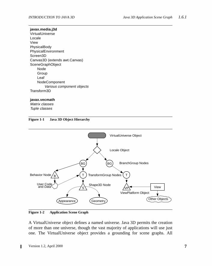
1.6.1 Java 3D Application Scene Graph
The scene graph for the sample application is shown in Figure 1-2.
The scene graph consists of superstructure components—a VirtualUnivobject and a Locale object—and a set of branch graphs. Each branch grapsubgraph that is rooted by a BranchGroup node that is attached to the superture. For more information, see Chapter 3, “Scene Graph Basics.”
The Java 3D API Specification
INTRODUCTION TO JAVA 3D Java 3D Application Scene Graph1.6.1
tionjustAll
Figure 1-1 Java 3D Object Hierarchy
Figure 1-2 Application Scene Graph
A VirtualUniverse object defines a named universe. Java 3D permits the creaof more than one universe, though the vast majority of applications will useone. The VirtualUniverse object provides a grounding for scene graphs.
javax.media.j3dVirtualUniverseLocaleViewPhysicalBodyPhysicalEnvironmentScreen3DCanvas3D (extends awt.Canvas)SceneGraphObject
NodeGroupLeafNodeComponent
Various component objectsTransform3D
javax.vecmathMatrix classesTuple classes
BG
VirtualUniverse Object
Locale Object
BranchGroup Nodes
BBehavior Node TT TransformGroup Nodes
SShape3D Node
Appearance Geometry
ViewPlatform Object
VPUser Code and Data
BG
View
Other Objects
7Version 1.2, April 2000
1.6.2 Recipe for a Java 3D Program INTRODUCTION TO JAVA 3D
8
yed.
nestualingle
5.2,ed a
to
des.of a
e for.
thateo-
fersTheour
eome-
roupitionns-ni-
thelat-a-that
raphand
Java 3D scene graphs must connect to a VirtualUniverse object to be displaFor more information, see Chapter 4, “Scene Graph Superstructure.”
Below the VirtualUniverse object is a Locale object. The Locale object defithe origin, in high-resolution coordinates, of its attached branch graphs. A viruniverse may contain as many Locales as needed. In this example, a sLocale object is defined with its origin at (0.0, 0.0, 0.0).
The scene graph itself starts with the BranchGroup nodes (see Section“BranchGroup Node”). A BranchGroup serves as the root of a subgraph, callbranch graph, of the scene graph. Only BranchGroup objects can attachLocale objects.
In this example there are two branch graphs and, thus, two BranchGroup noAttached to the left BranchGroup are two subgraphs. One subgraph consistsuser-extended Behavior leaf node. The Behavior node contains Java codmanipulating the transformation matrix associated with the object’s geometry
The other subgraph in this BranchGroup consists of a TransformGroup nodespecifies the position (relative to the Locale), orientation, and scale of the gmetric objects in the virtual universe. A single child, a Shape3D leaf node, reto two component objects: a Geometry object and an Appearance object.Geometry object describes the geometric shape of a 3D object (a cube insimple example). The Appearance object describes the appearance of the gtry (color, texture, material reflection characteristics, and so forth).
The right BranchGroup has a single subgraph that consists of a TransformGnode and a ViewPlatform leaf node. The TransformGroup specifies the pos(relative to the Locale), orientation, and scale of the ViewPlatform. This traformed ViewPlatform object defines the end user’s view within the virtual uverse.
Finally, the ViewPlatform is referenced by a View object that specifies all ofparameters needed to render the scene from the point of view of the ViewPform. Also referenced by the View object are other objects that contain informtion, such as the drawing canvas into which Java 3D renders, the screencontains the canvas, and information about the physical environment.
1.6.2 Recipe for a Java 3D Program
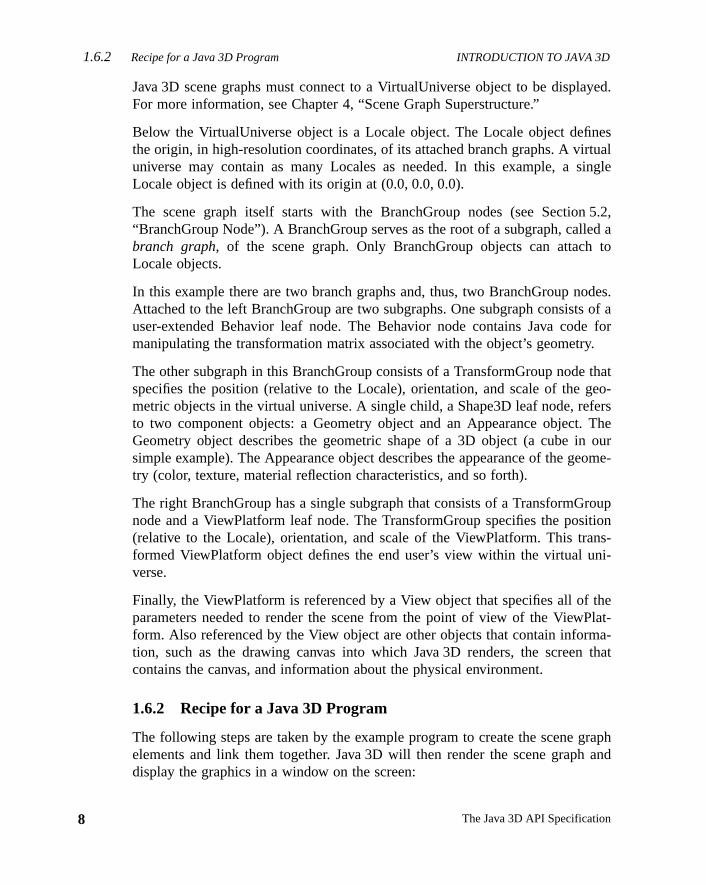
The following steps are taken by the example program to create the scene gelements and link them together. Java 3D will then render the scene graphdisplay the graphics in a window on the screen:
The Java 3D API Specification
INTRODUCTION TO JAVA 3D HelloUniverse: A Sample Java 3D Program1.6.3
ee
lat-
ph.
con-
s the
ludesh to
1. Create a Canvas3D object and add it to the Applet panel.
2. Create a BranchGroup as the root of the scene branch graph.
3. Construct a Shape3D node with a TransformGroup node above it.
4. Attach a RotationInterpolator behavior to the TransformGroup.
5. Call the simple universe utility function to do the following:
a. Establish a virtual universe with a single high-resolution Locale (sChapter 3, “Scene Graph Basics”).
b. Create the PhysicalBody, PhysicalEnvironment, View, and ViewPform objects.
c. Create a BranchGroup as the root of the view platform branch gra
d. Insert the view platform branch graph into the Locale.
6. Insert the scene branch graph into the simple universe’s Locale.
The Java 3D renderer then starts running in an infinite loop. The rendererceptually performs the following operations:
while(true) {Process inputIf (request to exit) breakPerform BehaviorsTraverse the scene graph and render visible objects
}Cleanup and exit
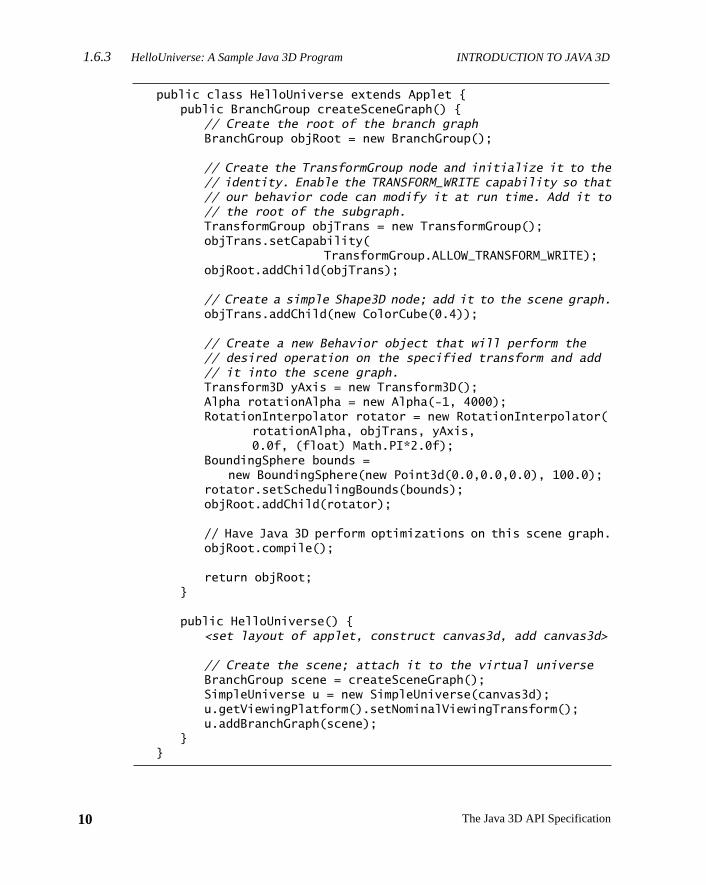
1.6.3 HelloUniverse: A Sample Java 3D Program
Following are code fragments from a simple program,HelloUniverse.java,that creates a cube and a RotationInterpolator behavior object that rotatecube at a constant rate ofπ/2 radians per second.
1.6.3.1 HelloUniverse Class
The HelloUniverse class, on the next page, creates the branch graph that incthe cube and the RotationInterpolator behavior. It then adds this branch grapthe Locale object generated by the SimpleUniverse utility.
9Version 1.2, April 2000
1.6.3 HelloUniverse: A Sample Java 3D Program INTRODUCTION TO JAVA 3D
10
public class HelloUniverse extends Applet {public BranchGroup createSceneGraph() {
// Create the root of the branch graphBranchGroup objRoot = new BranchGroup();
// Create the TransformGroup node and initialize it to the// identity. Enable the TRANSFORM_WRITE capability so that// our behavior code can modify it at run time. Add it to// the root of the subgraph.TransformGroup objTrans = new TransformGroup();objTrans.setCapability(
TransformGroup.ALLOW_TRANSFORM_WRITE);objRoot.addChild(objTrans);
// Create a simple Shape3D node; add it to the scene graph.objTrans.addChild(new ColorCube(0.4));
// Create a new Behavior object that will perform the// desired operation on the specified transform and add// it into the scene graph.Transform3D yAxis = new Transform3D();Alpha rotationAlpha = new Alpha(-1, 4000);RotationInterpolator rotator = new RotationInterpolator(
rotationAlpha, objTrans, yAxis,0.0f, (float) Math.PI*2.0f);
BoundingSphere bounds =new BoundingSphere(new Point3d(0.0,0.0,0.0), 100.0);
rotator.setSchedulingBounds(bounds);objRoot.addChild(rotator);
// Have Java 3D perform optimizations on this scene graph.objRoot.compile();
return objRoot;}
public HelloUniverse() {<set layout of applet, construct canvas3d, add canvas3d>
// Create the scene; attach it to the virtual universeBranchGroup scene = createSceneGraph();SimpleUniverse u = new SimpleUniverse(canvas3d);u.getViewingPlatform().setNominalViewingTransform();u.addBranchGraph(scene);
}}
The Java 3D API Specification
Version 1.2, April 2000
C H A P T E R 2
sly. Ittuto-this
videthe
impleam-
ome
hicalbjects.l howolds a. Leafscenellu-er toe notas the
ctings. A
Java 3D Concept
A specification serves to define objects, methods, and their actions preciseis not the best way to learn an API. Describing how to use an API belongs in arial or programmer’s reference manual—and that is well beyond the scope ofbook. However, a short introduction to the main concepts in Java 3D can prothe context for understanding the detailed, but isolated, specification found inremainder of this book.
This chapter introduces Java 3D concepts and illustrates them with some sprogram fragments. Appendix G, “The Example Programs” describes the exples included with the CD-ROM and highlights particular code segments for sexamples.
2.1 Basic Scene Graph Concepts
A scene graph is a “tree” structure that contains data arranged in a hierarcmanner. The scene graph consists of parent nodes, child nodes, and data oThe parent nodes, called Group nodes, organize and, in some cases, controJava 3D interprets their descendants. Group nodes serve as the glue that hscene graph together. Child nodes can be either Group nodes or Leaf nodesnodes have no children. They encode the core semantic elements of agraph— for example, what to draw (geometry), what to play (audio), how to iminate objects (lights), or what code to execute (behaviors). Leaf nodes refdata objects, called NodeComponent objects. NodeComponent objects arscene graph nodes, but they contain the data that Leaf nodes require, suchgeometry to draw or the sound sample to play.
A Java 3D application builds and manipulates a scene graph by construJava 3D objects and then later modifying those objects by using their method
11
2.1.1 Constructing a Simple Scene Graph JAVA 3D CONCEPTS
12
scene
cts insinglethenkingakear-
of atwo
arancenly aut anpe3Dn-
roupde,ctedsed in
ith it?cenerse.
Java 3D program first constructs a scene graph, then, once built, hands thatgraph to Java 3D for processing.
The structure of a scene graph determines the relationships among the objethe graph and determines which objects a programmer can manipulate as aentity. Group nodes provide a single point for handling or manipulating allnodes beneath it. A programmer can tune a scene graph appropriately by thiabout what manipulations an application will need to perform. He or she can ma particular manipulation easy or difficult by grouping or regrouping nodes in vious ways.
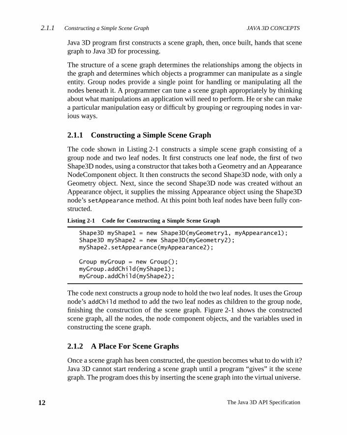
2.1.1 Constructing a Simple Scene Graph
The code shown in Listing 2-1 constructs a simple scene graph consistinggroup node and two leaf nodes. It first constructs one leaf node, the first ofShape3D nodes, using a constructor that takes both a Geometry and an AppeNodeComponent object. It then constructs the second Shape3D node, with oGeometry object. Next, since the second Shape3D node was created withoAppearance object, it supplies the missing Appearance object using the Shanode’ssetAppearance method. At this point both leaf nodes have been fully costructed.
The code next constructs a group node to hold the two leaf nodes. It uses the Gnode’saddChild method to add the two leaf nodes as children to the group nofinishing the construction of the scene graph. Figure 2-1 shows the construscene graph, all the nodes, the node component objects, and the variables uconstructing the scene graph.
2.1.2 A Place For Scene Graphs
Once a scene graph has been constructed, the question becomes what to do wJava 3D cannot start rendering a scene graph until a program “gives” it the sgraph. The program does this by inserting the scene graph into the virtual unive
Listing 2-1 Code for Constructing a Simple Scene Graph
Shape3D myShape1 = new Shape3D(myGeometry1, myAppearance1);Shape3D myShape2 = new Shape3D(myGeometry2);myShape2.setAppearance(myAppearance2);
Group myGroup = new Group();myGroup.addChild(myShape1);myGroup.addChild(myShape2);
The Java 3D API Specification
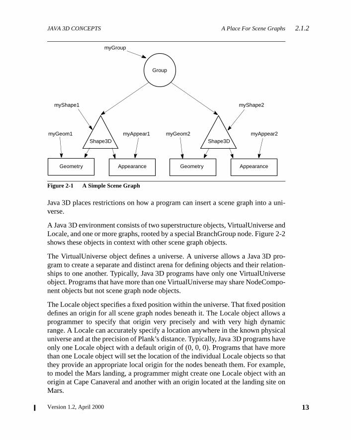
JAVA 3D CONCEPTS A Place For Scene Graphs2.1.2
uni-
ande 2-2
pro-tion-rse
mpo-
tionws aicical
haveorehatple,
h ane on
Figure 2-1 A Simple Scene Graph
Java 3D places restrictions on how a program can insert a scene graph into averse.
A Java 3D environment consists of two superstructure objects, VirtualUniverseLocale, and one or more graphs, rooted by a special BranchGroup node. Figurshows these objects in context with other scene graph objects.
The VirtualUniverse object defines a universe. A universe allows a Java 3Dgram to create a separate and distinct arena for defining objects and their relaships to one another. Typically, Java 3D programs have only one VirtualUniveobject. Programs that have more than one VirtualUniverse may share NodeConent objects but not scene graph node objects.
The Locale object specifies a fixed position within the universe. That fixed posidefines an origin for all scene graph nodes beneath it. The Locale object alloprogrammer to specify that origin very precisely and with very high dynamrange. A Locale can accurately specify a location anywhere in the known physuniverse and at the precision of Plank’s distance. Typically, Java 3D programsonly one Locale object with a default origin of (0, 0, 0). Programs that have mthan one Locale object will set the location of the individual Locale objects so tthey provide an appropriate local origin for the nodes beneath them. For examto model the Mars landing, a programmer might create one Locale object witorigin at Cape Canaveral and another with an origin located at the landing sitMars.
myGroup
Group
myShape1
myGeom1
Geometry
Shape3D Shape3DmyAppear1 myGeom2
Appearance Geometry Appearance
myAppear2
myShape2
13Version 1.2, April 2000
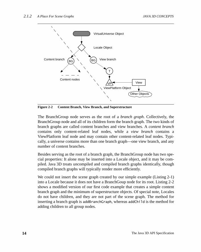
2.1.2 A Place For Scene Graphs JAVA 3D CONCEPTS
14
s of
ypi-d any
spe-om-ugh
2-1)2-2
ntentales
d for
Figure 2-2 Content Branch, View Branch, and Superstructure
The BranchGroup node serves as the root of abranch graph. Collectively, theBranchGroup node and all of its children form the branch graph. The two kindbranch graphs are called content branches and view branches. Acontent branchcontains only content-related leaf nodes, while aview branch contains aViewPlatform leaf node and may contain other content-related leaf nodes. Tcally, a universe contains more than one branch graph—one view branch, annumber of content branches.
Besides serving as the root of a branch graph, the BranchGroup node has twocial properties: It alone may be inserted into a Locale object, and it may be cpiled. Java 3D treats uncompiled and compiled branch graphs identically, thocompiled branch graphs will typically render more efficiently.
We could not insert the scene graph created by our simple example (Listinginto a Locale because it does not have a BranchGoup node for its root. Listingshows a modified version of our first code example that creates a simple cobranch graph and the minimum of superstructure objects. Of special note, Locdo not have children, and they are not part of the scene graph. The methoinserting a branch graph isaddBranchGraph, whereasaddChild is the method foradding children to all group nodes.
VirtualUniverse Object
Locale Object
View branch
T
ViewPlatform Object
VP
BG
View
Other Objects
BGContent branch
Content nodes
The Java 3D API Specification
JAVA 3D CONCEPTS Processing a Scene Graph2.1.4
nch
pli-otecase
as pos-ng as3Dall
2.1.3 SimpleUniverse Utility
Most Java 3D programs build an identical set of superstructure and view braobjects, so the Java 3D utility packages provide auniverse package for construct-ing and manipulating the objects in a view branch. The classes in theuniverse
package provide a quick means for building a single view (single window) apcation. Listing 2-3 shows a code fragment for using the SimpleUniverse class. Nthat the SimpleUniverse constructor takes a Canvas3D as an argument, in thisreferred to by the variablemyCanvas.
2.1.4 Processing a Scene Graph
When given a scene graph, Java 3D processes that scene graph as efficientlysible. How a Java 3D implementation processes a scene graph can vary, as lothe implementation conforms to the semantics of the API. In general, a Javaimplementation will render all visible objects, play all enabled sounds, execute
Listing 2-2 Code for Constructing a Scene Graph and Some Superstructure Objects
Shape3D myShape1 = new Shape3D(myGeometry1, myAppearance1);Shape3D myShape2 = new Shape3D(myGeometry2, myAppearance2);
BranchGroup myBranch = new BranchGroup();myBranch.addChild(myShape1);myBranch.addChild(myShape2);myBranch.compile();
VirtualUniverse myUniverse = new VirtualUniverse();Locale myLocale = new Locale(myUniverse);myLocale.addBranchGraph(myBranch);
Listing 2-3 Code for Constructing a Scene Graph Using the Universe Package
import com.sun.j3d.utils.universe.*;
Shape3D myShape1 = new Shape3D(myGeometry1, myAppearance1);Shape3D myShape2 = new Shape3D(myGeometry2, myAppearance2);
BranchGroup myBranch = new BranchGroup();myBranch.addChild(myShape1);myBranch.addChild(myShape2);myBranch.compile();
SimpleUniverse myUniv = new SimpleUniverse(myCanvas);myUniv.addBranchGraph(myBranch);
15Version 1.2, April 2000
2.2 Features of Java 3D JAVA 3D CONCEPTS
16
ener-
playjectfore itodes
wstrol
owsand
ntrolowsthey
res.ech-of anfirstiatedfying
threepace.
on-pingfallsentalmen-
light
triggered behaviors, process any identified input devices, and check for and gate appropriate collision events.
The order that a particular Java 3D implementation renders objects onto the disis carefully not defined. One implementation might render the first Shape3D oband then the second. Another might first render the second Shape3D node berenders the first one. Yet another implementation may render both Shape3D nin parallel.
2.2 Features of Java 3D
Java 3D allows a programmer to specify a broad range of information. It allocontrol over the shape of objects, their color, and transparency. It allows conover background effects, lighting, and environmental effects such as fog. It allcontrol over the placement of all objects (even nonvisible objects such as lightsbehaviors) in the scene graph and over their orientation and scale. It allows coover how those objects move, rotate, stretch, shrink, or morph over time. It allcontrol over what code should execute, what sounds should play, and howshould sound and change over time.
Java 3D provides different techniques for controlling the effect of various featuSome techniques act fairly locally, such as getting the color of a vertex. Other tniques have broader influence, such as changing the color or appearanceentire object. Still other techniques apply to a broad number of objects. In thetwo cases, the programmer can modify a particular object or an object assocwith the affected object. In the latter case, Java 3D provides a means for specimore than one object spatially.
2.2.1 Bounds
Bounds objects allow a programmer to define a volume in space. There areways to specify this volume: as a box, a sphere, or a set of planes enclosing a s
Bounds objects specify a volume in which particular operations apply. Envirmental effects such as lighting, fog, alternate appearance, and model clipplanes use bounds objects to specify their region of influence. Any object thatwithin the space defined by the bounds object has the particular environmeffect applied. The proper use of bounds objects can ensure that these environtal effects are applied only to those objects in a particular volume, such as aapplying only to the objects within a single room.
The Java 3D API Specification
JAVA 3D CONCEPTS Live and/or Compiled2.2.3
undsands thatro-
play.
iewle, thed for
ectsthatave aca-
nd,ith
ither
nodey thebestple
g
Bounds objects are also used to specify a region of action. Behaviors and soexecute or play only if they are close enough to the viewer. The use of behaviorsound bounds objects allows Java 3D to cull away those behaviors and soundare too far away to affect the viewer (listener). By using bounds properly, a pgrammer can ensure that only the relevant behaviors and sounds execute or
Finally, bounds objects are used to specify a region of application for per-voperations such as background, clip, and soundscape selection. For exampbackground node whose region of application is closest to the viewer is selectea given view.
2.2.2 Nodes
All scene graph nodes have an implicit location in space of (0, 0, 0). For objthat exist in space, this implicit location provides a local coordinate system forobject, a fixed reference point. Even abstract objects that may not seem to hwell-defined location, such as behaviors and ambient lights, have this implicit lotion. An object’s location provides an origin for its local coordinate system ajust as importantly, an origin for any bounding volume information associated wthat object.
2.2.3 Live and/or Compiled
All scene graph objects, including nodes and node component objects, are epart of an active universe or not. An object is said to belive if it is part of an activeuniverse. Additionally, branch graphs are eithercompiledor not. When a node iseither live or compiled, Java 3D enforces access restrictions to nodes andcomponent objects. Java 3D allows only those operations that are enabled bprogram before a node or node component becomes live or is compiled. It isto set capabilities when you build your content. Listing 2-4 shows an examwhere we create a TransformGroup node and enable it for writing.
By setting the capability to write the transform, Java 3D will allow the followincode to execute:
myTrans.setTransform3D(myT3D);
However, the following code will cause an exception:
myTrans.getTransform3D(myT3D);
Listing 2-4 Capabilities Example
TransformGroup myTrans = new TransformGroup();myTrans.setCapability(Transform.ALLOW_TRANSFORM_WRITE);
17Version 1.2, April 2000

2.2.3 Live and/or Compiled JAVA 3D CONCEPTS
18
ding
ssarys thetion
The reason for the exception is that the TransformGroup is not enabled for rea(ALLOW_TRANSFORM_READ).
It is important to ensure that all needed capabilities are set and that unnececapabilities are not set. The process of compiling a branch graph examinecapability bits and uses that information to reduce the amount of computaneeded to run a program.
The Java 3D API Specification
Version 1.2, April 2000
C H A P T E R 3
sm to arep-hs incene
noderoupThetionsnodends,cs of
. Thencur-jects.rticular
n therouptains
Scene Graph Basic
A scene graph consists of Java 3D objects, callednodes, arranged in a treestructure. The user creates one or more scene subgraphs and attaches thevirtual universe. The individual connections between Java 3D nodes alwaysresent a directed relationship: parent to child. Java 3D restricts scene grapone major way: Scene graphs may not contain cycles. Thus, a Java 3D sgraph is a directed acyclic graph (DAG). See Figure 3-1.
Java 3D refines the Node object class into two subclasses: Group and Leafobjects. Group node objects group together one or more child nodes. A gnode can point to zero or more children but can have only one parent.SharedGroup node cannot have any parents (although it allows sharing porof a scene graph, as described in Chapter 7, “Reusing Scene Graphs”). Leafobjects contain the actual definitions of shapes (geometry), lights, fog, souand so forth. A leaf node has no children and only one parent. The semantithe various group and leaf nodes are described in subsequent chapters.
3.1 Scene Graph Structure
A scene graph organizes and controls the rendering of its constituent objectsJava 3D renderer draws a scene graph in a consistent way that allows for corence. The Java 3D renderer can draw one object independently of other obJava 3D can allow such independence because its scene graphs have a paform and cannot share state among branches of a tree.
3.1.1 Spatial Separation
The hierarchy of the scene graph encourages a natural spatial grouping ogeometric objects found at the leaves of the graph. Internal nodes act to gtheir children together. A group node also defines a spatial bound that con
19
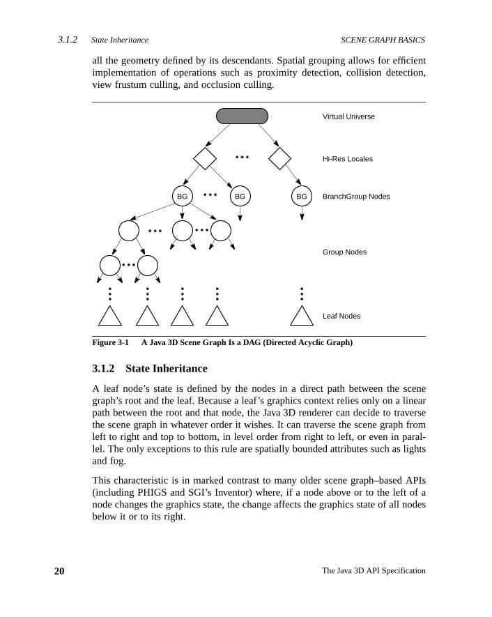
3.1.2 State Inheritance SCENE GRAPH BASICS
20
iention,
cenenearversefroml-ghts
APIsf anodes
all the geometry defined by its descendants. Spatial grouping allows for efficimplementation of operations such as proximity detection, collision detectview frustum culling, and occlusion culling.
Figure 3-1 A Java 3D Scene Graph Is a DAG (Directed Acyclic Graph)
3.1.2 State Inheritance
A leaf node’s state is defined by the nodes in a direct path between the sgraph’s root and the leaf. Because a leaf’s graphics context relies only on a lipath between the root and that node, the Java 3D renderer can decide to trathe scene graph in whatever order it wishes. It can traverse the scene graphleft to right and top to bottom, in level order from right to left, or even in paralel. The only exceptions to this rule are spatially bounded attributes such as liand fog.
This characteristic is in marked contrast to many older scene graph–based(including PHIGS and SGI’s Inventor) where, if a node above or to the left onode changes the graphics state, the change affects the graphics state of allbelow it or to its right.
BG BG BG
Virtual Universe
Hi-Res Locales
BranchGroup Nodes
Leaf Nodes
Group Nodes
The Java 3D API Specification

SCENE GRAPH BASICS Scene Graph Objects 3.2
thatroup.
nstit-ode
rmitserial
directect.es.
con-bjectsret class
com-
sired
bjects—via
tire2,
sseditlyrrapha
tion-is-s
The most common node object, along the path from the root to the leaf,changes the graphics state is the TransformGroup object. The TransformGobject can change the position, orientation, and scale of the objects below it
Most graphics state attributes are set by a Shape3D leaf node through its couent Appearance object, thus allowing parallel rendering. The Shape3D nalso has a constituent Geometry object that specifies its geometry—this pedifferent shape objects to share common geometry without sharing matattributes (or vice versa).
3.1.3 Rendering
The Java 3D renderer incorporates all graphics state changes made in apath from a scene graph root to a leaf object in the drawing of that leaf objJava 3D provides this semantic for both retained and compiled-retained mod
3.2 Scene Graph Objects
A Java 3D scene graph consists of a collection of Java 3D node objectsnected in a tree structure. These node objects reference other scene graph ocallednode component objects. All scene graph node and component objects asubclasses of a common SceneGraphObject class. The SceneGraphObjecis an abstract class that defines methods that are common among nodes andponent objects.
Scene graph objects are constructed by creating a new instance of the declass and are accessed and manipulated using the object’sset andget methods.Once a scene graph object is created and connected to other scene graph oto form a subgraph, the entire subgraph can be attached to a virtual universea high-resolution Locale object—making the objectlive (see Section 4.6.2,“Locale Object”). Prior to attaching a subgraph to a virtual universe, the ensubgraph can becompiled into an optimized, internal format (see Section 5.“BranchGroup Node”).
An important characteristic of all scene graph objects is that they can be acceor modified only during the creation of a scene graph, except where explicallowed. Access to mostset andget methods of objects that are part of a live ocompiled scene graph is restricted. Such restrictions provide the scene gcompiler with usage information it can use in optimally compiling or renderingscene graph. Each object has a set of capability bits that enable certain funcality when the object is live or compiled. By default, all capability bits are dabled (cleared). Only thoseset andget methods corresponding to capability bit
21Version 1.2, April 2000
3.2 Scene Graph Objects SCENE GRAPH BASICS
22
liveext.
cenebythatd to a
mod-bil-veryam-
or
that are explicitly enabled (set) prior to the object being compiled or madeare legal. The methods for setting and getting capability bits are described n
Constructors
The SceneGraphObject specifies one constructor.
public SceneGraphObject()
Constructs a new SceneGraphObject with default parameters:
Methods
The following methods are available on all scene graph objects:
public final boolean isCompiled()public final boolean isLive()
The first method returns a flag that indicates whether the node is part of a sgraph that has been compiled. If so, only those capabilities explicitly allowedthe object’s capability bits are allowed. The second method returns a flagindicates whether the node is part of a scene graph that has been attachevirtual universe via a high-resolution Locale object.
public final boolean getCapability(int bit)public final void setCapability(int bit)public final void clearCapability(int bit)
These three methods provide applications with the means for accessing andifying the capability bits of a scene graph object. The bit positions of the capaity bits are defined as public static final constants on a per-object basis. Einstance of every scene graph object has its own set of capability bits. An exple of a capability bit is theALLOW_BOUNDS_WRITE bit in node objects. Only thosemethods corresponding to capabilities that are enabledbefore the object is firstcompiled or made live are subsequently allowed for that object. ARestricted-
AccessException is thrown if an application callssetCapability or clearCap-ability on live or compiled objects. Note that only a single bit may be setcleared per method invocation—bits maynot be ORed together.
Parameters Default Values
capability bits clear (all bits)
isLive false
isCompiled false
userData null
The Java 3D API Specification
SCENE GRAPH BASICS Node Objects3.2.1
ceney be
—it isied
odesde’sering:
arede
ndi-live
th
ble
od(s)
public void setUserData(Object userData)public Object getUserData()
These methods access or modify the userData field associated with this sgraph object. The userData field is a reference to an arbitrary object and maused to store any user-specific data associated with this scene graph objectnot used by the Java 3D API. If this object is cloned, the userData field is copto the newly cloned object.
3.2.1 Node Objects
Node objects divide into group node objects and leaf node objects. Group nserve to group their child node objects together according to the group nosemantics. Leaf nodes specify the actual elements that Java 3D uses in rendspecifically, geometric objects, lights, and sounds. These node objectsdescribed in Chapter 5, “Group Node Objects” and Chapter 6, “Leaf NoObjects.”
Constants
Node object constants allow an application to enable runtime capabilities ividually. These capability bits are enforced only when the node is part of aor compiled scene graph.
public static final int ALLOW_BOUNDS_READpublic static final int ALLOW_BOUNDS_WRITE
These bits, when set using thesetCapability method, specify that the node willpermit an application to invoke thegetBounds andsetBounds methods, respec-tively. An application can choose to enable a particularset method but not theassociatedget method, or vice versa. The application can choose to enable bomethods or, by default, leave the method(s) disabled.
public static final int ALLOW_AUTO_COMPUTE_BOUNDS_READpublic static final int ALLOW_AUTO_COMPUTE_BOUNDS_WRITE
These bits, when set using thesetCapability method, specify that the node willpermit an application to invoke thegetBoundsAutoCompute and set-
BoundsAutoCompute methods, respectively. An application can choose to enaa particularset method but not the associatedget method, or vice versa. Theapplication can choose to enable both methods or, by default, leave the methdisabled.
23Version 1.2, April 2000
3.2.1 Node Objects SCENE GRAPH BASICS
24
By
ph-; itriorPath
ility
s-to-
Thees a
und-
public static final int ENABLE_PICK_REPORTING
This flag specifies that this node will be reported in a SceneGraphPath.default, this is disabled.
public static final int ALLOW_PICKABLE_READpublic static final int ALLOW_PICKABLE_WRITE
These flags specify that this Node can have its pickability read or changed.
public static final int ENABLE_COLLISION_REPORTING
This flag specifies that this Node will be reported in the collision SceneGraPath if a collision occurs. This capability is specifiable only for Group nodesis ignored for Leaf nodes. The default for Group nodes is false. Only intenodes that have this flag set to true will be reported in the SceneGraph(unless they are needed for uniqueness).
public static final int ALLOW_COLLIDABLE_READpublic static final int ALLOW_COLLIDABLE_WRITE
These flags specify that this Node allows read or write access to its collidabstate.
public static final int ALLOW_LOCAL_TO_VWORLD_READ
This flag specifies that this node allows read access to its local-coordinatevirtual-world-(Vworld)-coordinates transform.
Constructors
The Node object specifies the following constructor:
public Node()
This constructor constructs and initializes a Node object with default values.Node class provides an abstract class for all group and leaf nodes. It providcommon framework for constructing a Java 3D scene graph, specifically, boing volumes. The default values are:
Parameters Default Value
pickable true
collidable true
boundsAutoCompute true
bounds N/A (automatically computed)
The Java 3D API Specification
SCENE GRAPH BASICS Node Objects3.2.1
ities
df a
rans-ent.ds-eneec-
cep-ep-
omet-ad-
n bek-
Methods
The following methods are available on Node objects, subject to the capabilthat are enabled for live or compiled nodes:
public Node getParent()
Retrieves the parent of this node, ornull if this node has no parent. This methois valid only during the construction of the scene graph. If this object is part olive or compiled scene graph, aRestrictedAccessException will be thrown.
public Bounds getBounds()public void setBounds(Bounds bounds)
These methods access or modify this node’s geometric bounds.
public void getLocalToVworld(Transform3D t)public void getLocalToVworld(SceneGraphPath path, Transform3D t)
These methods access the local-coordinates-to-virtual-world-coordinates tform for this node and place the result into the specified Transform3D argumThe first form is used for nodes that arenot part of a shared subgraph; the seconform is used for nodes thatare part of a shared subgraph. The local-coordinateto-Vworld-coordinates transform is the composite of all transforms in the scgraph from the root down to this node (via the specified Link nodes, in the sond case). It is valid only for nodes that are part of a live scene graph. An extion will be thrown if the node is not part of a live scene graph or if thappropriate capability is not set. Additionally, the first form will throw an excetion if the node is part of a shared subgraph.
public void setBoundsAutoCompute(boolean autoCompute)public boolean getBoundsAutoCompute()
These methods set and get the value that determines whether the node’s geric bounds are computed automatically, in which case the bounds will be reonly, or are set manually, in which case the value specified bysetBounds will beused. The default is automatic.
public void setPickable(boolean pickable)public boolean getPickable()
These methods set and retrieve the flag indicating whether this node capicked. A setting offalse means that this node and its children are all unpicable.
25Version 1.2, April 2000
3.2.2 NodeComponent Objects SCENE GRAPH BASICS
26
ableode,odelueion
ibutesd in
faultmpo-
ref-
public void setCollidable(boolean collidable)public boolean getCollidable()
The set method sets the collidable value. The get method returns the collidvalue. This value determines whether this node and its children, if a group ncan be considered for collision purposes. If the value is false, neither this nnor any children nodes will be traversed for collision purposes. The default vais true. The collidable setting is the way that an application can perform collisculling.
3.2.2 NodeComponent Objects
Node component objects include the actual geometry and appearance attrused to render the geometry. These component objects are describeChapter 8, “Node Component Objects.”
Constructors
The NodeComponent object specifies the following constructor:
public NodeComponent()
This constructor constructs and initializes a NodeComponent object with deparameters. The NodeComponent class provides an abstract class for all conent objects. The default values are as follows:
Methods
The following methods are available on NodeComponent objects:
public void setDuplicateOnCloneTree(boolean duplicate)public boolean getDuplicateOnCloneTree()
These methods access or modify theduplicateOnCloneTree value of the Node-Component object. TheduplicateOnCloneTree value is used by thecloneTreemethod to determine if NodeComponent objects should be duplicated or justerenced in the cloned leaf object.
Parameters Default Value
duplicateOnCloneTree false
The Java 3D API Specification
SCENE GRAPH BASICS Scene Graph Viewing Objects3.4
andthe
cene
ec-willionsthinn.
ceneation
toaph
tualr of
f theg orsub-
cenes intoody,iew
3.3 Scene Graph Superstructure Objects
Java 3D defines two scene graph superstructure objects, VirtualUniverseLocale, which are used to contain collections of subgraphs that comprisescene graph. These objects are described in more detail in Chapter 4, “SGraph Superstructure.”
3.3.1 VirtualUniverse Object
A VirtualUniverse object consists of a list of Locale objects that contain a colltion of scene graph nodes that exist in the universe. Typically, an applicationneed only one VirtualUniverse, even for very large virtual databases. Operaton a VirtualUniverse include enumerating the Locale objects contained withe universe. See Section 4.6.1, “VirtualUniverse Object,” for more informatio
3.3.2 Locale Object
The Locale object acts as a container for a collection of subgraphs of the sgraph that are rooted by a BranchGroup node. A Locale also defines a locwithin the virtual universe using high-resolution coordinates (HiResCoord)specify its position. The HiResCoord serves as the origin for all scene grobjects contained within the Locale.
A Locale has no parent in the scene graph but is implicitly attached to a viruniverse when it is constructed. A Locale may reference an arbitrary numbeBranchGroup nodes but has no explicit children.
The coordinates of all scene graph objects are relative to the HiResCoord oLocale in which they are contained. Operations on a Locale include settingetting the HiResCoord of the Locale, adding a subgraph, and removing agraph (see Section 4.6.2, “Locale Object,” for more information).
3.4 Scene Graph Viewing Objects
Java 3D defines five scene graph viewing objects that are not part of the sgraph per se but serve to define the viewing parameters and to provide hookthe physical world. These objects are Canvas3D, Screen3D, View, PhysicalBand PhysicalEnvironment. They are described in more detail in Chapter 9, “VModel,” and Appendix C, “View Model Details.”
27Version 1.2, April 2000
3.4.1 Canvas3D Object SCENE GRAPH BASICS
28
win-n as theame
phys-en intion
aph.the
ofinctstive
h therth.
iatedkerment
3.4.1 Canvas3D Object
The Canvas3D object encapsulates all of the parameters associated with thedow being rendered into (see Section 9.9, “The Canvas3D Object”). WheCanvas3D object is attached to a View object, the Java 3D traverser renderspecified view onto the canvas. Multiple Canvas3D objects can point to the sView object.
3.4.2 Screen3D Object
The Screen3D object encapsulates all of the parameters associated with theical screen containing the canvas, such as the width and height of the screpixels, the physical dimensions of the screen, and various physical calibravalues (see Section 9.8, “The Screen3D Object”).
3.4.3 View Object
The View object specifies information needed to render the scene grFigure 3-2 shows a View object attached to a simple scene graph for viewingscene.
The View object is the central Java 3D object for coordinating all aspectsviewing (see Section 9.7, “The View Object”). All viewing parametersJava 3D are directly contained either within the View object or within objepointed to by a View object. Java 3D supports multiple simultaneously acView objects, each of which can render to one or more canvases.
3.4.4 PhysicalBody Object
The PhysicalBody object encapsulates all of the parameters associated witphysical body, such as head position, right and left eye position, and so fo(see Section 9.10, “The PhysicalBody Object”).
3.4.5 PhysicalEnvironment Object
The PhysicalEnvironment object encapsulates all of the parameters assocwith the physical environment, such as calibration information for the tracbase for the head or hand tracker (see Section 9.11, “The PhysicalEnvironObject”).
The Java 3D API Specification
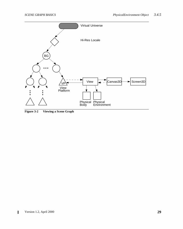
SCENE GRAPH BASICS PhysicalEnvironment Object3.4.5
Figure 3-2 Viewing a Scene Graph
Virtual Universe
Hi-Res Locale
BG
VP View Canvas3D Screen3D
ViewPlatform
PhysicalBody
PhysicalEnvironment
29Version 1.2, April 2000

Version 1.2, April 2000
C H A P T E R 4
reachhe
cene
hegatean be
a sin-
thanrsee.
thatslessigh-
levelorto a
ans-artic-on
Scene Graph Superstructu
JAVA 3D’s superstructure consists of one or more VirtualUniverse objects, eof which contains a set of one or more high-resolution Locale objects. TLocale objects, in turn, contain collections of subgraphs that comprise the sgraph (see Figure 4-1).
4.1 The Virtual Universe
Java 3D defines the concept of avirtual universeas a three-dimensional space witan associated set of objects. Virtual universes serve as the largest unit of aggrrepresentation, and can also be thought of as databases. Virtual universes cvery large, both in physical space units and in content. Indeed, in most casesgle virtual universe will serve an application’s entire needs.
Virtual universes are separate entities in that no node object may exist in moreone virtual universe at any one time. Likewise, the objects in one virtual univeare not visible in, nor do they interact with objects in, any other virtual univers
To support large virtual universes, Java 3D introduces the concept of Localeshavehigh-resolution coordinatesas an origin. Think of high-resolution coordinateas “tie-downs” that precisely anchor the locations of objects specified usingprecise floating-point coordinates that are within the range of influence of the hresolution coordinates.
A Locale, with its associated high-resolution coordinates, serves as the nextof representation down from a virtual universe. All virtual universes contain onemore high-resolution-coordinate Locales, and all other objects are attachedLocale. High-resolution coordinates act as an upper-level translation-only trform node. For example, the coordinates of all objects that are attached to a pular Locale are all relative to the location of that Locale’s high-resoluticoordinates.
31
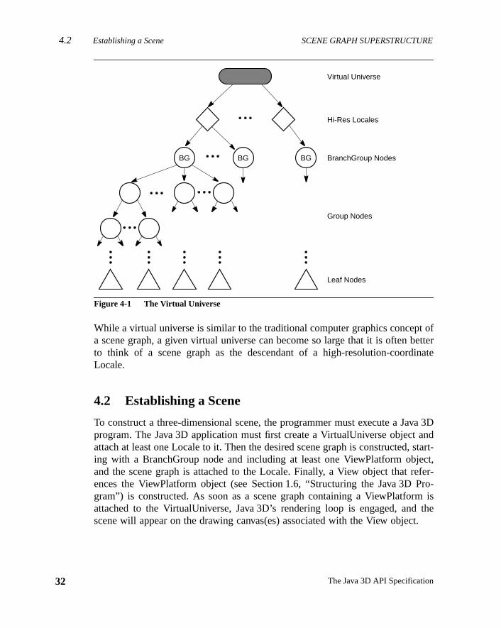
4.2 Establishing a Scene SCENE GRAPH SUPERSTRUCTURE
32
t ofetter
inate
va 3Dandstart-ct,
efer-Pro-m is
thet.
Figure 4-1 The Virtual Universe
While a virtual universe is similar to the traditional computer graphics concepa scene graph, a given virtual universe can become so large that it is often bto think of a scene graph as the descendant of a high-resolution-coordLocale.
4.2 Establishing a Scene
To construct a three-dimensional scene, the programmer must execute a Japrogram. The Java 3D application must first create a VirtualUniverse objectattach at least one Locale to it. Then the desired scene graph is constructed,ing with a BranchGroup node and including at least one ViewPlatform objeand the scene graph is attached to the Locale. Finally, a View object that rences the ViewPlatform object (see Section 1.6, “Structuring the Java 3Dgram”) is constructed. As soon as a scene graph containing a ViewPlatforattached to the VirtualUniverse, Java 3D’s rendering loop is engaged, andscene will appear on the drawing canvas(es) associated with the View objec
BG BG BG
Virtual Universe
Hi-Res Locales
BranchGroup Nodes
Leaf Nodes
Group Nodes
The Java 3D API Specification
SCENE GRAPH SUPERSTRUCTURE Java 3D High-Resolution Coordinates4.5.1
at.tualpro-or
tion
d-sentuni-riginintsore
ear
res-ents
ers,derseectsowe of
4.3 Loading a Virtual Universe
Java 3D is a runtime application programming interface (API), not a file formAs an API, Java 3D provides no direct mechanism for loading or storing a viruniverse. Constructing a scene graph involves the execution of a Java 3Dgram. However, loaders to convert a number of standard 3D file formats tofrom Java 3D virtual universes are expected to be generally available.
4.4 Coordinate Systems
By default, Java 3D coordinate systems are right-handed, with the orientasemantics being that +y is the local gravitational up, +x is horizontal to the right,and +z is directly toward the viewer. The default units are meters.
4.5 High-Resolution Coordinates
Double-precision floating-point, single-precision floating-point, or even fixepoint representations of three-dimensional coordinates are sufficient to repreand display rich 3D scenes. Unfortunately, scenes are not worlds, let aloneverses. If one ventures even a hundred miles away from the (0.0, 0.0, 0.0) ousing only single-precision floating-point coordinates, representable pobecome quite quantized, to at very best a third of an inch (and much mcoarsely than that in practice).
To “shrink” down to a small size (say the size of an IC transistor), even very n(0.0, 0.0, 0.0), the same problem arises.
If a large contiguous virtual universe is to be supported, some form of higher-olution addressing is required. Thus the choice of 256-bit positional componfor “high-resolution” positions.
4.5.1 Java 3D High-Resolution Coordinates
Java 3D high-resolution coordinates consist of three 256-bit fixed-point numbone each forx, y, andz. The fixed point is at bit 128, and the value 1.0 is defineto be exactly 1 meter. This coordinate system is sufficient to describe a univin excess of several hundred billion light years across, yet still define objsmaller than a proton (down to below the planck length). Table 4-1 shows hmany bits are needed above or below the fixed point to represent the ranginteresting physical dimensions.
33Version 1.2, April 2000
4.5.2 Java 3D Virtual World Coordinates SCENE GRAPH SUPERSTRUCTURE
34
ctly
onal. Incan
reethis
xed-pre-nates0 asningt isres-
A 256-bit fixed-point number also has the advantage of being able to direrepresent nearly any reasonable single-precision floating-point valueexactly.
High-resolution coordinates in Java 3D are used only to embed more traditifloating point coordinate systems within a much higher-resolution substratethis way a visually seamless virtual universe of any conceivable size or scalebe created, without worry about numerical accuracy.
4.5.2 Java 3D Virtual World Coordinates
Within a given virtual world coordinate system, positions are expressed by thfloating point numbers. The virtual world coordinate scale is in meters, butcan be affected by scale changes in the object hierarchy.
4.5.3 Details of High-Resolution Coordinates
High-resolution coordinates are represented as signed, two’s-complement, fipoint numbers consisting of 256 bits. Although Java 3D keeps the internal resentation of high-resolution coordinates opaque, users specify such coordiusing 8-element integer arrays. Java 3D treats the integer found at indexcontaining the most significant bits and the integer found at index 7 as contaithe least significant bits of the high-resolution coordinate. The binary poinlocated at bit position 128, or between the integers at index 3 and 4. A high-olution coordinate of 1.0 is 1 meter.
Table 4-1 Java 3D High-Resolution Coordinates
2n Meters Units
87.29 Universe (20 billion light years)
69.68 Galaxy (100,000 light years)
53.07 Light year
43.43 Solar system diameter
23.60 Earth diameter
10.65 Mile
9.97 Kilometer
0.00 Meter
–19.93 Micron
–33.22 Angstrom
–115.57 Planck length
The Java 3D API Specification
SCENE GRAPH SUPERSTRUCTURE Details of High-Resolution Coordinates4.5.3
p toingice is
ela-iont; ad then in
uterter-ence
the
eingnewraph) by
thentsialsolu-3D
ateuffi-i-
yes inriatepli-
itslydis-ce
The semantics of how file loaders deal with high-resolution coordinates is uthe individual file loader, as Java 3D does not directly define any file-loadsemantics. However, some general advice can be given (note that this advnot officially part of the Java 3D specification).
For “small” virtual universes (on the order of hundreds of meters across in rtive scale), a single Locale with high-resolution coordinates at locat(0.0, 0.0, 0.0) as the root node (below the VirtualUniverse object) is sufficienloader can automatically construct this node during the loading process, anpoint in high-resolution coordinates does not need any direct representatiothe external file.
Larger virtual universes are expected to be constructed usually like compdirectory hierarchies, that is, as a “root” virtual universe containing mostly exnal file references to embedded virtual universes. In this case, the file referobject (user-specific data hung off a Java 3D group or hi-res node) defineslocation for the data to be read into the current virtual universe.
The data file’s contents should be parented to the file object node while bread, thus inheriting the high-resolution coordinates of the file object as therelative virtual universe origin of the embedded scene graph. If this scene gitself contains high-resolution coordinates, it will need to be offset (translatedthe amount in the file object’s high-resolution coordinates and then added tolarger virtual universe as new high-resolution coordinates, with their contehung off below them. Once again, this procedure is not part of the officJava 3D specification, but some more details on the care and use of high-retion coordinates in external file formats will probably be available as a Javaapplication note.
Authoring tools that directly support high-resolution coordinates should creadditional high-resolution coordinates as a user creates new geometry “sciently” far away (or of different scale) from existing high-resolution coordnates.
Semantics of widely moving objects. Most fixed and nearly-fixed objects staattached to the same high-resolution Locale. Objects that make wide changposition or scale may periodically need to be reparented to a more approphigh-resolution Locale. If no appropriate high-resolution Locale exists, the apcation may need to create a new one.
Semantics of viewing. The ViewPlatform object and the associated nodes inhierarchy are very often widely moving objects. Applications will typicalattach the view platform to the most appropriate high-resolution Locale. Forplay, all objects will first have their positions translated by the differen
35Version 1.2, April 2000
4.6 API for Superstructure Objects SCENE GRAPH SUPERSTRUCTURE
36
's, no
ord
be
ni-
uni-ss ofas
thiss ofd
New in 1.2
New in 1.2
between the location of their high-resolution Locale and the view platformhigh-resolution Locale. (In the common case of the Locales being the sametranslation is necessary.)
4.6 API for Superstructure Objects
This section describes the API for the VirtualUniverse, Locale, and HiResCoobjects.
4.6.1 VirtualUniverse Object
The VirtualUniverse object consists of a set of Locale objects.
Constructors
The VirtualUniverse object has the following constructors:
public VirtualUniverse()
This constructs a new VirtualUniverse object. This VirtualUniverse can thenused to create Locale objects.
Methods
The VirtualUniverse object has the following methods:
public Enumeration getAllLocales()public int numLocales()
The first method returns the Enumeration object of all Locales in this virtual uverse. ThenumLocales method returns the number of Locales.
public void removeLocale(Locale locale)
This method removes a Locale and its associates branch graphs from thisverse. All branch graphs within the specified Locale are detached, regardlewhether theirALLOW_DETACH capability bits are set. The Locale is then markedbeing dead: No branch graphs may subsequently be attached.
public void removeAllLocales()
This method removes all Locales and their associates branch graphs fromuniverse. All branch graphs within each Locale are detached, regardleswhether theirALLOW_DETACH capability bits are set. Each Locale is then marke
The Java 3D API Specification
SCENE GRAPH SUPERSTRUCTURE Locale Object4.6.2
ethodits
fault
rdi-
peci-at
ified
rdi-
ds,
on-
ew in 1.2
ew in 1.2
as being dead: No branch graphs may subsequently be attached. This mshould be called by applications and applets to allow Java 3D to clean upresources.
public static void setJ3DThreadPriority(int priority)public static int getJ3DThreadPriority()
These methods set and retrieve the priority of all Java 3D threads. The devalue is the priority of the thread that started Java 3D.
4.6.2 Locale Object
The Locale object consists of a point, specified using high-resolution coonates, and a set of subgraphs, rooted by BranchGroup node objects.
Constructors
The Locale object has the following constructors:
public Locale(VirtualUniverse universe)public Locale(VirtualUniverse universe, int x[], int y[], int z[])public Locale(VirtualUniverse universe, HiResCoord hiRes)
These three constructors create a new high-resolution Locale object in the sfied VirtualUniverse. The first form constructs a Locale object located(0.0, 0.0, 0.0). The other two forms construct a Locale object using the spechigh-resolution coordinates. In the second form, the parametersx, y, andz arearrays of eight 32-bit integers that specify the respective high-resolution coonate.
Methods
The Locale object has the following methods. For the Locale picking methosee Section 11.3.2, “BranchGroup Node and Locale Node Pick Methods.”
public VirtualUniverse getVirtualUniverse()
This method retrieves the virtual universe within which this Locale object is ctained.
public void setHiRes(int x[], int y[], int z[])public void setHiRes(HiResCoord hiRes)public void getHiRes(HiResCoord hiRes)
These methods set or get the high-resolution coordinates of this Locale.
N
N
37Version 1.2, April 2000
4.6.3 HiResCoord Object SCENE GRAPH SUPERSTRUCTURE
38
cale.helast
rdi-ers.bit256-t sig-
reeluesreso-
.
the
public void addBranchGraph(BranchGroup branchGroup)public void removeBranchGraph(BranchGroup branchGroup)public void replaceBranchGraph(BranchGroup oldGroup, BranchGroup newGroup)public int numBranchGraphs()public Enumeration getAllBranchGraphs()
The first three methods add, remove, and replace a branch graph in this LoAdding a branch graph has the effect of making the branch graph “live.” Tfourth method retrieves the number of branch graphs in this Locale. Themethod retrieves an Enumeration object of all branch graphs.
4.6.3 HiResCoord Object
A HiResCoord object defines a point using a set of three high-resolution coonates, each of which consists of three two’s-complement fixed-point numbEach high-resolution number consists of 256 total bits with a binary point at128. Java 3D uses integer arrays of length eight to define or extract a singlebit coordinate value. Java 3D interprets the integer at index 0 as the 32 mosnificant bits and the integer at index 7 as the 32 least significant bits.
Constructors
The HiResCoord object has the following constructors:
public HiResCoord(int x[], int y[], int z[])public HiResCoord(HiResCoord hc)public HiResCoord()
The first constructor generates the high-resolution coordinate point from thinteger arrays of length eight. The integer arrays specify the coordinate vacorresponding with their name. The second constructor creates a new high-lution coordinate point by cloning the high-resolution coordinateshc. The thirdconstructor creates new high-resolution coordinates with value (0.0, 0.0, 0.0)
Methods
public void setHiResCoord(int x[], int y[], int z[])public void setHiResCoord(HiResCoord hiRes)public void setHiResCoordX(int x[])public void setHiResCoordY(int y[])public void setHiResCoordZ(int z[])
These five methods modify the value of high-resolution coordinatesthis. Thefirst method resets all three coordinate values with the values specified by
The Java 3D API Specification
SCENE GRAPH SUPERSTRUCTURE HiResCoord Object4.6.3
e-
ceshaveof the
and
rdi-
cales
-
thod
three integer arrays. The second method sets the value ofthis to that of high-resolution coordinateshiRes. The third, fourth, and fifth methods reset the corrsponding coordinate ofthis.
public void getHiResCoord(int x[], int y[], int z[])public void getHiResCoord(HiResCoord hc)public void getHiResCoordX(int x[])public void getHiResCoordY(int y[])public void getHiResCoordZ(int z[])
These five methods retrieve the value of the high-resolution coordinatesthis.The first method retrieves the high-resolution coordinates’ values and plathose values into the three integer arrays specified. All three arrays mustlength greater than or equal to eight. The second method updates the valuehigh-resolution coordinateshc to match the value ofthis. The third, fourth, andfifth methods retrieve the coordinate value that corresponds to their nameupdate the integer array specified, which must be of length eight or greater.
public void add(HiResCoord h1, HiResCoord h2)public void sub(HiResCoord h1, HiResCoord h2)
These two methods perform arithmetic operations on high-resolution coonates. The first method addsh1 to h2 and stores the result inthis. The secondmethod subtractsh2 from h1 and stores the result inthis.
public void scale(int scale, HiResCoord h1)public void scale(int scale)
These methods scale a high-resolution coordinate point. The first method sh1 by the scalar valuescale and places the scaled coordinates intothis. Thesecond method scalesthis by the scalar valuescale and places the scaled coordinates back intothis.
public void negate(HiResCoord h1)public void negate()
These two methods negate a high-resolution coordinate point. The first menegatesh1 and stores the result inthis. The second method negatesthis andstores its negated value back intothis.
39Version 1.2, April 2000
4.6.3 HiResCoord Object SCENE GRAPH SUPERSTRUCTURE
40
n
uble-
, it
a
inatethatnted
public void difference(HiResCoord h1, Vector3d v)
This method subtractsh1 from this and stores the resulting difference vector ithe double-precision floating-point vectorv. Note that although the individualhigh-resolution coordinate points cannot be represented accurately by doprecision numbers, this difference vector between themcan be accurately repre-sented by doubles for many practical purposes, such as viewing.
public boolean equals(HiResCoord h1)public boolean equals(Object o1)
The first method performs an arithmetic comparison betweenthis and h1. Itreturnstrue if the two high-resolution coordinate points are equal; otherwisereturnsfalse. The second method returns true if the Objecto1 is of type HiRes-Coord and all of the data members ofo1 are equal to the corresponding datmembers in this HiResCoord.
public double distance(HiResCoord h1)
This method computes the linear distance between high-resolution coordpoints this and h1 and returns this value expressed as a double. Notealthough the individual high-resolution coordinate points cannot be represeaccurately by double precision numbers, this distance between themcanbe accu-rately represented by a double for many practical purposes.
The Java 3D API Specification
Version 1.2, April 2000
C H A P T E R 5
s. Thedefi-s—asso-lesshooseer-
haven aner-ing,s of
Group Node Object
GROUP nodes are the glue elements used in constructing a scene graphfollowing subsections list the seven group nodes (see Figure 5-1) and theirnitions. All group nodes can have a variable number of child node objectincluding other group nodes as well as leaf nodes. These children have anciated index that allows operations to specify a particular child. However, unone of the special ordered group nodes is used, the Java 3D renderer can cto render a group node’s children in whatever order it wishes (including rending the children in parallel).
Figure 5-1 Group Node Hierarchy
5.1 Group Node
The Group node object is a general-purpose grouping node. Group nodesexactly one parent and an arbitrary number of children that are rendered iunspecified order (or in parallel). Null children are allowed; no operation is pformed on a null child node. Operations on Group node objects include addremoving, and enumerating the children of the Group node. The subclasseGroup node add additional semantics.
SceneGraphObjectNode
GroupBranchGroupOrderedGroup
DecalGroupSharedGroupSwitchTransformGroup
41
5.1 Group Node GROUP NODE OBJECTS
42
om-
thod
The
Constants
public static final int ALLOW_CHILDREN_READpublic static final int ALLOW_CHILDREN_WRITEpublic static final int ALLOW_CHILDREN_EXTEND
These flags, when enabled using thesetCapability method, specify that thisGroup node will allow the following methods, respectively:
• numChildren, getChild, getAllChildren
• setChild, insertChild, removeChild
• addChild, moveTo
These capability bits are enforced only when the node is part of a live or cpiled scene graph.
public static final int ALLOW_COLLISION_BOUNDS_READpublic static final int ALLOW_COLLISION_BOUNDS_WRITE
These flags, when enabled using thesetCapability method, specify that thisGroup node will allow reading and writing of its collision bounds.
Constructors
public Group()
Constructs and initializes a Group node object with default parameters:
collision bounds = nullalternate collision target = false
Methods
The Group node class defines the following methods:
public int numChildren()public Node getChild(int index)
The first method returns a count of the number of children. The second mereturns the child at the specified index.
public void setChild(Node child, int index)public void insertChild(Node child, int index)public void removeChild(int index)
The first method replaces the child at the specified index with a new child.
The Java 3D API Specification
GROUP NODE OBJECTS Group Node 5.1
Theup
y beet.
thisdes
thethis
leds.
argetlli-bit-
eithup
second method inserts a new child before the child at the specified index.third method removes the child at the specified index. Note that if this Gronode is part of a live or compiled scene graph, only BranchGroup nodes maadded to or removed from it—and only if the appropriate capability bits are s
public Enumeration getAllChildren()
This method returns an Enumeration object of all children.
public void addChild(Node child)
This method adds a new child as the last child in the group. Note that ifGroup node is part of a live or compiled scene graph, only BranchGroup nomay be added to it—and only if the appropriate capability bits are set.
public void moveTo(BranchGroup branchGroup)
This method moves the specified BranchGroup node from its old location inscene graph to the end of this group, in an atomic manner. Functionally,method is equivalent to the following lines:
branchGroup.detach();this.addChild(branchGroup);
If either this Group or the specified BranchGroup is part of a live or compiscene graph, the appropriate capability bits must be set in the affected node
public Bounds setCollisionBounds(Bounds bounds)public Bounds getCollisionBounds()
These methods set and retrieve the collision bounding object for a node.
public void setAlternateCollisionTarget(boolean target)public boolean getAlternateCollisionTarget()
The set method causes this Group node to be reported as the collision twhen collision is being used and this node or any of its children are in a cosion. The default is false. This method tries to set the capabilityNode.ENABLE_COLLISION_REPORTING. The get method returns the collision target state.
For collision with USE_GEOMETRY set, the collision traverser will check thgeometry of all the Group node’s leaf descendants. For collision wUSE_BOUNDS set, the collision traverser will check the bounds at this Gro
43Version 1.2, April 2000
5.2 BranchGroup Node GROUP NODE OBJECTS
44
the
as ain
ht of
s areeir
o a
beset.
ome
g is
node. In both cases, if there is a collision, this Group node will be reported ascolliding object in the SceneGraphPath.
5.2 BranchGroup Node
A BranchGroup is the root of a subgraph of a scene that may be compiledunit, attached to a virtual universe, or included as a child of a group nodeanother subgraph. A subgraph, rooted by a BranchGroup node, can be thougas a compile unit. The following may be done with BranchGroup:
• A BranchGroup may be compiled by calling itscompile method. Thiscauses the entire subgraph to be compiled. If any BranchGroup nodecontained within the subgraph, they are compiled as well (along with thdescendants).
• A BranchGroup may be inserted into a virtual universe by attaching it tLocale. The entire subgraph is then said to belive.
• A BranchGroup that is contained within another subgraph mayreparented or detached at run time if the appropriate capabilities areSee Figure 5-2.
Note that if a BranchGroup is included in another subgraph, as a child of sother group node, it may not be attached to a Locale.
Constants
The BranchGroup class adds the following new constant:
public static final int ALLOW_DETACH
This flag, when enabled using thesetCapability method, allows this Branch-Group node to be detached from its parent group node. This capability flaenforced only when the node is part of a live or compiled scene graph.
Constructors
public BranchGroup()
Constructs and initializes a new BranchGroup node object.
Methods
The BranchGroup class defines the following methods:
The Java 3D API Specification
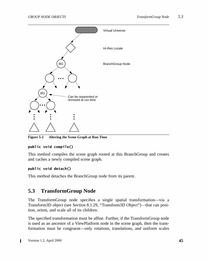
GROUP NODE OBJECTS TransformGroup Node 5.3
eates
a aosi-
odetrans-ales
Figure 5-2 Altering the Scene Graph at Run Time
public void compile()
This method compiles the scene graph rooted at this BranchGroup and crand caches a newly compiled scene graph.
public void detach()
This method detaches the BranchGroup node from its parent.
5.3 TransformGroup Node
The TransformGroup node specifies a single spatial transformation—viTransform3D object (see Section 8.1.29, “Transform3D Object”)—that can ption, orient, and scale all of its children.
The specified transformation must be affine. Further, if the TransformGroup nis used as an ancestor of a ViewPlatform node in the scene graph, then theformation must be congruent—only rotations, translations, and uniform sc
BG
Virtual Universe
Hi-Res Locale
BGCan be reparented orremoved at run time
BranchGroup Node
45Version 1.2, April 2000
5.3 TransformGroup Node GROUP NODE OBJECTS
46
n
for-ing
tena-thethatVir-ns-aree ofof aaluedingjects
rt of
esial-
are allowed in a direct path from a Locale to a ViewPlatform node. ABadTrans-
formException (see Section D.1, “BadTransformException”) is thrown if aattempt is made to specify an illegal transform.
Note: Even though arbitrary affine transformations are allowed, better permance will result if all matrices within a branch graph are congruent—containonly rotations, translation, anduniformscale.
The effects of transformations in the scene graph are cumulative. The concation of the transformations of each TransformGroup in a direct path fromLocale to a Leaf node defines a composite model transformation (CMT)takes points in that Leaf node’s local coordinates and transforms them intotual World (Vworld) coordinates. This composite transformation is used to traform points, normals, and distances into Vworld coordinates. Pointstransformed by the CMT. Normals are transformed by the inverse-transposthe CMT. Distances are transformed by the scale of the CMT. In the casetransformation containing a nonuniform scale or shear, the maximum scale vin any direction is used. This ensures, for example, that a transformed bounsphere, which is specified as a point and a radius, continues to enclose all obthat are also transformed using a nonuniform scale.
Constants
The TransformGroup class adds the following new flags:
public static final int ALLOW_TRANSFORM_READpublic static final int ALLOW_TRANSFORM_WRITE
These flags, when enabled using thesetCapability method, allow this node’sTransform3D to be read or written. They are used only when the node is paa live or compiled scene graph.
Constructors
public TransformGroup()public TransformGroup(Transform3D t1)
These construct and initialize a new TransformGroup. The first form initializthe node’s Transform3D to the identity transformation; the second form initizes the node’s Transform3D to a copy of the specified transform.
The Java 3D API Specification
GROUP NODE OBJECTS DecalGroup Node 5.5
opy-
d byoded
, theecur-set-
theirof the
roupther
ed in
Methods
The TransformGroup class defines the following methods:
public void setTransform(Transform3D t1)public void getTransform(Transform3D t1)
These methods retrieve or set this node’s attached Transform3D object by cing the transform to or from the specified object.
public Node cloneNode(boolean forceDuplicate)public void duplicateNode(Node originalNode, boolean forceDuplicate)
The first method creates a new instance of the node. This method is callecloneTree to duplicate the current node. The second method copies all the ninformation from theoriginalNode into the current node. This method is callefrom thecloneNode method, which in turn is called by thecloneTree method.
For each NodeComponent object contained by the object being duplicatedNodeComponent’sduplicateOnCloneTree flag is used to determine whether thNodeComponent should be duplicated in the new node or a reference to therent node should be placed in the new node. This flag can be overridden byting theforceDuplicate parameter in thecloneTree method totrue.
5.4 OrderedGroup Node
The OrderedGroup node guarantees that Java 3D will render its children inindex order. Only the OrderedGroup node and its subclasses make any useorder of their children during rendering.
Constructors
public OrderedGroup()
Constructs and initializes a new OrderedGroup node object.
5.5 DecalGroup Node
The DecalGroup node is a subclass of the OrderedGroup node. The DecalGnode is an ordered group node used for defining decal geometry on top of ogeometry. The DecalGroup node specifies that its children should be render
47Version 1.2, April 2000
5.6 Switch Node GROUP NODE OBJECTS
48
inted
renoth-
h offirstse,opla-
uescesdis-
oup
allychil-renct-
nly
index order and that they generate coplanar objects. Examples include padecals or text on surfaces and a checkerboard layered on top of a table.
The first child, at index 0, defines the surface on top of which all other childare rendered. The geometry of this child must encompass all other children;erwise, incorrect rendering may result. The polygons contained within eacthe children must be facing the same way. If the polygons defined by thechild are front facing, then all other surfaces should be front facing. In this cathe polygons are rendered in order. The renderer can use knowledge of the cnar nature of the surfaces to avoidZ-buffer collisions. (If, for example, the under-lying implementation supports stenciling or polygon offset, then these techniqmay be employed.) If the main surface is back facing, then all other surfashould be back facing and need not be rendered (even if back-face culling isabled).
Note that using the DecalGroup node does not guarantee thatZ-buffer collisionsare avoided. An implementation of Java 3D may fall back to treating DecalGrnode as an ordinary OrderedGroup node.
Constructors
public DecalGroup()
Constructs and initializes a new DecalGroup node object.
5.6 Switch Node
The Switch group node allows a Java 3D application to choose dynamicamong a number of subgraphs. The Switch node contains an ordered list ofdren and a switch value. The switch value determines which child or childJava 3D will render. Note that the index order of children is used only for seleing the appropriate child or children—it does not specify rendering order.
Constants
public static final int ALLOW_SWITCH_READpublic static final int ALLOW_SWITCH_WRITE
These flags, when enabled using thesetCapability method, allow reading andwriting of the values that specify the child-selection criteria. They are used owhen the node is part of a live or compiled scene graph.
The Java 3D API Specification
GROUP NODE OBJECTS Switch Node 5.6
icateof
rate
ers.
willr it
t the
public static final int CHILD_NONEpublic static final int CHILD_ALLpublic static final int CHILD_MASK
These values, when used in place of a nonnegative integer index value, indwhich children of the Switch node are selected for rendering. A valueCHILD_NONE indicates that no children are rendered. A value ofCHILD_ALL indi-cates that all children are rendered, effectively making this Switch node opeas an ordinary Group node. A value ofCHILD_MASK indicates that thechildMaskBitSet is used to select the children that are rendered.
Constructors
public Switch()
Constructs a Switch node with default parameters:
public Switch(int whichChild)public Switch(int whichChild, BitSet childMask)
These constructors initialize a new Switch node using the specified paramet
Methods
The Switch node class defines the following methods:
public void setWhichChild(int whichChild)public int getWhichChild()
These methods access or modify the index of the child that the Switch objectdraw. The value may be a nonnegative integer, indicating a specific child, omay be one of the following constants:CHILD_NONE, CHILD_ALL, or CHILD_MASK.If the specified value is out of range, then no children are drawn.
public void setChildMask(BitSet childMask)public BitSet getChildMask()
These methods access or modify the mask used to select the children thaSwitch object will draw when thewhichChild parameter isCHILD_MASK. Thisparameter is ignored during rendering if thewhichChild parameter is a valueother thanCHILD_MASK.
Parameters Default Values
child selection index CHILD_NONE
child selection mask false (for all children)
49Version 1.2, April 2000
5.7 SharedGroup Node GROUP NODE OBJECTS
50
ph inoup
public Node currentChild()
This method returns the currently selected child. IfwhichChild is out of range,or is set toCHILD_MASK, CHILD_ALL, or CHILD_NONE, thennull is returned.
5.7 SharedGroup Node
A SharedGroup node provides a mechanism for sharing the same subgradifferent parts of the tree via a Link node. See Section 7.1.1, “SharedGrNode,” for a description of this node.
The Java 3D API Specification
Version 1.2, April 2000
C H A P T E R 6
The
chil-kingformhe
st ofonent
Theolor,for
Leaf Node Objects
L EAF nodes define atomic entities such as geometry, lights, and sounds.leaf nodes and their associated meanings follow.
6.1 Leaf Node
The Leaf node is an abstract class for all scene graph nodes that have nodren. Leaf nodes specify lights, geometry, and sounds; provide special linand instancing capabilities for sharing scene graphs; and provide a view platfor positioning and orienting a view in the virtual world. Figure 6-1 shows tLeaf node object hierarchy.
Constructors
public Leaf()
Constructs and initializes a new Leaf object.
6.2 Shape3D Node
The Shape3D leaf node object specifies all geometric objects. It contains a lione or more Geometry component objects and a single Appearance compobject. The Geometry objects define the shape node’s geometric data.Appearance object specifies that object’s appearance attributes, including cmaterial, texture, and so on. See Chapter 8, “Node Component Objects”details of the Geometry and Appearance objects.
51
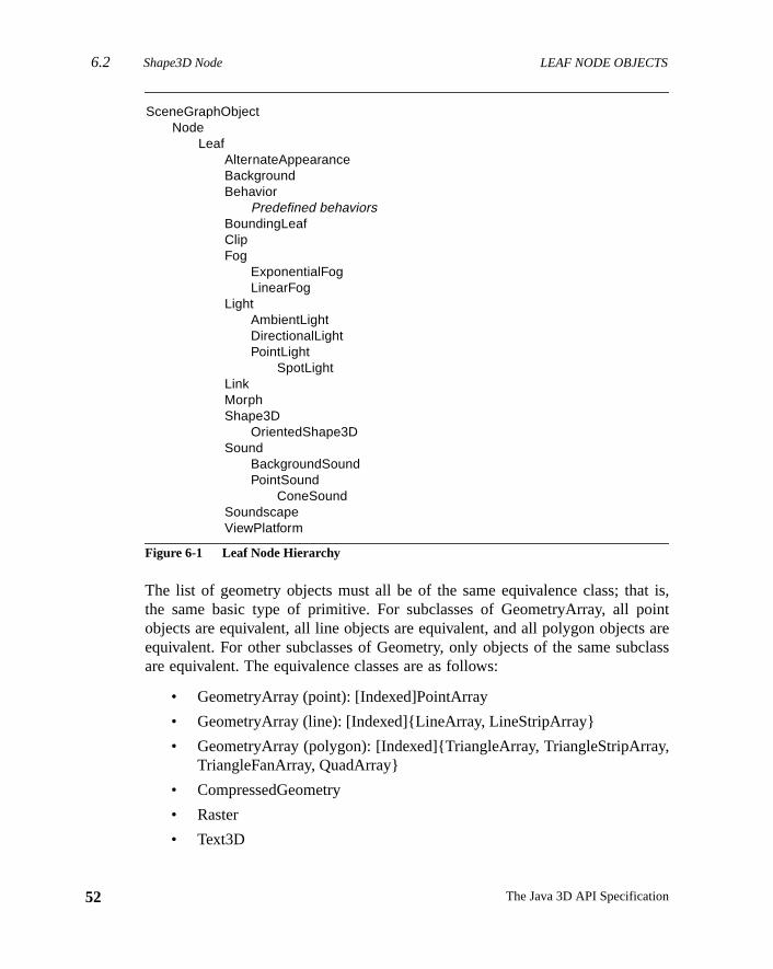
6.2 Shape3D Node LEAF NODE OBJECTS
52
t is,oint
areclass
,
Figure 6-1 Leaf Node Hierarchy
The list of geometry objects must all be of the same equivalence class; thathe same basic type of primitive. For subclasses of GeometryArray, all pobjects are equivalent, all line objects are equivalent, and all polygon objectsequivalent. For other subclasses of Geometry, only objects of the same subare equivalent. The equivalence classes are as follows:
• GeometryArray (point): [Indexed]PointArray
• GeometryArray (line): [Indexed]{LineArray, LineStripArray}
• GeometryArray (polygon): [Indexed]{TriangleArray, TriangleStripArrayTriangleFanArray, QuadArray}
• CompressedGeometry
• Raster
• Text3D
SceneGraphObjectNode
LeafAlternateAppearanceBackgroundBehavior
Predefined behaviorsBoundingLeafClipFog
ExponentialFogLinearFog
LightAmbientLightDirectionalLightPointLight
SpotLightLinkMorphShape3D
OrientedShape3DSound
BackgroundSoundPointSound
ConeSoundSoundscapeViewPlatform
The Java 3D API Specification
LEAF NODE OBJECTS Shape3D Node 6.2
ionflags
entifiesfault
ifiedcified
s isan
ew in 1.2
ew in 1.2
Constants
The Shape3D node object defines the following flags:
public static final int ALLOW_GEOMETRY_READpublic static final int ALLOW_GEOMETRY_WRITEpublic static final int ALLOW_APPEARANCE_READpublic static final int ALLOW_APPEARANCE_WRITEpublic static final int ALLOW_COLLISION_BOUNDS_WRITEpublic static final int ALLOW_COLLISION_BOUNDS_READpublic static final int ALLOW_APPEARANCE_OVERRIDE_WRITEpublic static final int ALLOW_APPEARANCE_OVERRIDE_READ
These flags, when enabled using thesetCapability method, allow reading andwriting of the Geometry and Appearance component objects, the collisbounds, and the appearance override enable, respectively. These capabilityare enforced only when the node is part of a live or compiled scene graph.
Constructors
The Shape3D node object defines the following constructors:
public Shape3D()
Constructs a Shape3D node with default parameters:
The list of geometry components is initialized with a null geometry componas the single element with an index of 0. A null geometry component specthat no geometry is drawn. A null appearance component specifies that devalues are used for all appearance attributes.
public Shape3D(Geometry geometry, Appearance appearance)public Shape3D(Geometry geometry)
The first form constructs and initializes a new Shape3D object with the specgeometry and appearance components. The second form uses the spegeometry and anull appearance component. The list of geometry componentinitialized with the specified geometry component as the single element withindex of 0. If the geometry component isnull, no geometry is drawn. A null
Parameter Default Value
appearance null (default values are used for all appearance attributes)
geometry { null }
collisionBounds null
appearanceOverrideEnable false
N
N
53Version 1.2, April 2000
6.2 Shape3D Node LEAF NODE OBJECTS
54
rance
d with-the
om-tingeom-gon,
de’s
t of
from
om-po-
lencehers.fied
ode’stheoint,
New in 1.2
New in 1.2
New in 1.2
New in 1.2
New in 1.2
appearance component specifies that default values are used for all appeaattributes.
Methods
The Shape3D node object defines the following methods:
public void setGeometry(Geometry geometry)public void setGeometry(Geometry geometry, int index)public Geometry getGeometry()public Geometry getGeometry(int index)
These methods access or modify the Geometry component object associatethis Shape3D node. The firstsetGeometry method replaces the geometry component at index 0 in this Shape3D node’s list of geometry components withspecified geometry component. The secondsetGeometry method replaces thegeometry component at the specified index in this Shape3D node’s list of geetry components with the specified geometry component. If there are exisgeometry components in the list (besides the one being replaced), the new getry component must be of the same equivalence class (point, line, polyCompressedGeometry, Raster, Text3D) as the others. The firstgetGeometry
method retrieves the geometry component at index 0 from this Shape3D nolist of geometry components. The secondgetGeometry method retrieves thegeometry component at the specified index from this Shape3D node’s lisgeometry components.
public void insertGeometry(Geometry geometry, int index)public void removeGeometry(int index)
These methods insert and remove the specified geometry component into orthis Shape3D node’s list of geometry components. TheinsertGeometry methodinserts the specified geometry component into this Shape3D node’s list of geetry components at the specified index. If there are existing geometry comnents in the list, the new geometry component must be of the same equivaclass (point, line, polygon, CompressedGeometry, Raster, Text3D) as the otThe removeGeometry method removes the geometry component at the speciindex from this Shape3D node’s list of geometry components.
public void addGeometry(Geometry geometry)
This method appends the specified geometry component to this Shape3D nlist of geometry components. If there are existing geometry components inlist, the new geometry component must be of the same equivalence class (pline, polygon, CompressedGeometry, Raster, Text3D) as the others.
The Java 3D API Specification
LEAF NODE OBJECTS OrientedShape3D Node6.2.1
etry
ode’stheoint,
ciated
nder
pear-errid-
5,
spec-tion
this
ew in 1.2
ew in 1.2
ew in 1.2
ew in 1.2
ew in 1.2
public Enumeration getAllGeometries()
This method returns an enumeration of this Shape3D node’s list of geomcomponents.
public int numGeometries()
This method appends the specified geometry component to this Shape3D nlist of geometry components. If there are existing geometry components inlist, the new geometry component must be of the same equivalence class (pline, polygon, CompressedGeometry, Raster, Text3D) as the others.
public void setAppearance(Appearance appearance)public Appearance getAppearance()
These methods access or modify the Appearance component object assowith this Shape3D node. Setting it tonull results in default attribute use.
public void setCollisionBounds(Bounds bounds)public Bounds getCollisionBounds()
These methods set and retrieve the collision bounds for this node.
public boolean intersect(SceneGraphPath path, PickShape pickShape)public boolean intersect(SceneGraphPath path, PickRay pickRay, double[] dist)
These two methods check if the geometry component of this shape node upath intersects with the pickShape.
public void setAppearanceOverrideEnable(boolean flag)public boolean getAppearanceOverrideEnable()
These methods set and retrieve the flag that indicates whether this node’s apance can be overridden. If the flag is true, this node’s appearance may be ovden by an AlternateAppearance leaf node, regardless of the value of theALLOW_
APPEARANCE_WRITE capability bit. The default value is false. See Section 6.1“AlternateAppearance Node.”
6.2.1 OrientedShape3D Node
The OrientedShape3D leaf node is a Shape3D node that is oriented along aified axis or about a specified point. It defines an alignment mode and a rotapoint or axis. This will cause the local +z axis of the object to point at theviewer’s eye position. This is done regardless of the transforms aboveOrientedShape3D node in the scene graph.
N
N
N
N
N
55Version 1.2, April 2000
6.2.1 OrientedShape3D Node LEAF NODE OBJECTS
56
iorentoup.
winghat
n,of a
ren’s
New in 1.2
New in 1.2
New in 1.2
New in 1.2
New in 1.2
New in 1.2
New in 1.2
New in 1.2
The OrientedShape3D node is similar in functionality to the Billboard behav(see Section 10.8, “Billboard Behavior”), but OrientedShape3D nodes will orithemselves correctly for each view, and they can be used within a SharedGr
If the alignment mode isROTATE_AXIS, the rotation will be around the specifiedaxis. If the alignment mode isROTATE_ABOUT_POINT, the rotation will be aboutthe specified point, with an additional rotation to align the +y axis of the Trans-formGroup with the +y axis in the View.
OrientedShape3D nodes are ideal for drawing screen-aligned text or for draroughly symmetrical objects. A typical use might consist of a quadrilateral tcontains a texture of a tree.
Constants
The OrientedShape3D node object defines the following flags:
public static final int ALLOW_MODE_READpublic static final int ALLOW_MODE_WRITEpublic static final int ALLOW_AXIS_READpublic static final int ALLOW_AXIS_WRITEpublic static final int ALLOW_POINT_READpublic static final int ALLOW_POINT_WRITE
These flags, when enabled using thesetCapability method, allow reading andwriting of the alignment mode, alignment axis, and rotation point informatiorespectively. These capability flags are enforced only when the node is partlive or compiled scene graph.
public static final int ROTATE_ABOUT_AXIS
Specifies that rotation should be about the specified axis.
public static final int ROTATE_ABOUT_POINT
Specifies that rotation should be about the specified point and that the childy-axis should match the view object’sy-axis.
Constructors
The OrientedShape3D node specifies the following constructors:
The Java 3D API Specification
LEAF NODE OBJECTS OrientedShape3D Node6.2.1
t val-
ifiedd con-com-
s one
hich
hich
ew in 1.2
ew in 1.2
ew in 1.2
ew in 1.2
ew in 1.2
ew in 1.2
ew in 1.2
ew in 1.2
ew in 1.2
ew in 1.2
ew in 1.2
public OrientedShape3D()
Constructs an OrientedShape3D node with default parameters. The defaulues are as follows:
public OrientedShape3D(Geometry geometry, Appearance appearance, int mode, Vector3f axis)public OrientedShape3D(Geometry geometry, Appearance appearance, int mode, Point3f point)
The first constructor constructs an OrientedShape3D node with the specgeometry component, appearance component, mode, and axis. The seconstructor constructs an OrientedShape3D node with the specified geometryponent, appearance component, mode, and rotation point.
Methods
public void setAlignmentMode(int mode)public int getAlignmentMode()
These methods set and retrieve the alignment mode. The alignment mode iof ROTATE_ABOUT_AXIS or ROTATE_ABOUT_POINT.
public void setAlignmentAxis(Vector3f axis)public void setAlignmentAxis(float x, float y, float z)public void getAlignmentAxis(Vector3f axis)
These methods set and retrieve the alignment axis. This is the ray about wthis OrientedShape3D rotates when the mode isROTATE_ABOUT_AXIS.
public void setRotationPoint(Point3f point)public void setRotationPoint(float x, float y, float z)public void getRotationPoint(Point3f point)
These methods set and retrieve the rotation point. This is the point about wthe OrientedShape3D rotates when the mode isROTATE_ABOUT_POINT.
Parameter Default Value
alignmentMode ROTATE_ABOUT_AXIS
alignmentAxis y-axis (0,1,0)
rotationPoint (0,0,1)
N
N
N
N
N
N
N
N
N
N
N
57Version 1.2, April 2000
6.3 BoundingLeaf Node LEAF NODE OBJECTS
58
ncedacti-gionrdi-canned
temocalf howachlocalthem-
ocalof a
ion
6.3 BoundingLeaf Node
The BoundingLeaf node defines a bounding region object that can be refereby other leaf nodes to define a region of influence (Fog and Light nodes), anvation region (Background, Clip, and Soundscape nodes), or a scheduling re(Sound and Behavior nodes). The bounding region is defined in the local coonate system of the BoundingLeaf node. A reference to a BoundingLeaf nodebe used in place of a locally defined bounds object for any of the aforementioregions.
This allows an application to specify a bounding region in one coordinate sys(the local coordinate system of the BoundingLeaf node) other than the lcoordinate system of the node that references the bounds. For an example othis might be used, consider a closed room with a number of track lights. Elight can move independently of the other lights and, as such, needs its owncoordinate system. However, the bounding volume is used by all the lights inboundary of the room, which doesn’t move when the lights move. In this exaple, the BoundingLeaf node allows the bounding region to be defined in the lcoordinate system of the room, rather than in the local coordinate systemparticular light. All lights can then share this single bounding volume.
Constants
The BoundingLeaf node object defines the following flags:
public static final int ALLOW_REGION_READpublic static final int ALLOW_REGION_WRITE
These flags, when enabled using thesetCapability method, allow an applica-tion to invoke methods that respectively read and write the bounding regobject.
Constructors
The BoundingLeaf node object defines the following constructors:
public BoundingLeaf()
Constructs a BoundingLeaf node with a null (empty) bounding region.
public BoundingLeaf(Bounds region)
Constructs a BoundingLeaf node with the specified bounding region.
The Java 3D API Specification
LEAF NODE OBJECTS Background Node 6.4
ack-me.. Alat-
ck-are
, theare
Methods
public void setRegion(Bounds region)public Bounds getRegion()
These methods set and retrieve the BoundingLeaf node’s bounding region.
6.4 Background Node
The Background leaf node defines either a solid background color or a bground image that is used to fill the window at the beginning of each new fraIt also specifies an application region in which this Background node is activeBackground node is active when its application region intersects the ViewPform’s activation volume. If multiple Background nodes are active, the Baground node that is “closest” to the eye will be used. If no Background nodesactive, then the window is cleared to black.
Constants
The Background node object defines the following flags:
public static final int ALLOW_APPLICATION_BOUNDS_READpublic static final int ALLOW_APPLICATION_BOUNDS_WRITEpublic static final int ALLOW_IMAGE_READpublic static final int ALLOW_IMAGE_WRITEpublic static final int ALLOW_COLOR_READpublic static final int ALLOW_COLOR_WRITEpublic static final int ALLOW_GEOMETRY_READpublic static final int ALLOW_GEOMETRY_WRITE
These flags, when enabled using thesetCapability method, allow an applica-tion to invoke methods that respectively read and write the application regionimage, the color, and the background geometry. These capability flagsenforced only when the node is part of a live or compiled scene graph.
Constructors
The Background node object defines the following constructors:
public Background()
Constructs a Background leaf node with default parameters:
59Version 1.2, April 2000
6.4 Background Node LEAF NODE OBJECTS
60
lor.age.ry.
not
e. Ifr orThe
public Background(Color3f color)public Background(float r, float g, float b)public Background(ImageComponent2D image)public Background(Branchgroup branch)
The first two forms construct a Background leaf node with the specified coThe second form constructs a Background leaf node with the specified 2D imThe final form constructs a Background leaf node with the specified geomet
Methods
The Background node object defines the following methods:
public void getColor(Color3f color)public void setColor(Color3f color)public void setColor(float r, float g, float b)
These three methods access or modify the background color.
public ImageComponent2D getImage()public void setImage(ImageComponent2D image)
These two methods access or modify the background image. If the image isnull then it is used in place of the color.
public void setGeometry(BranchGroup branch)public BranchGroup getGeometry()
These two methods access or modify the Background geometry. ThesetGeome-
try method sets the background geometry to the specified BranchGroup nodnon-null, this background geometry is drawn on top of the background coloimage using a projection matrix that essentially puts the geometry at infinity.geometry should be pretessellated onto a unit sphere.
Parameter Default Value
color black (0,0,0)
image null
geometry null
applicationBounds null
applicationBoundingLeaf null
The Java 3D API Specification
LEAF NODE OBJECTS Clip Node 6.5
nds.leaf
i-
und-
vir-is
lat-is
Cliptive,
andpart
public void setApplicationBounds(Bounds region)public Bounds getApplicationBounds()
These two methods access or modify the Background node’s application bouThis bounds is used as the application region when the application boundingis set tonull. ThegetApplicationBounds method returns a copy of the assocated bounds.
public void setApplicationBoundingLeaf(BoundingLeaf region)public BoundingLeaf getApplicationBoundingLeaf()
These two methods access or modify the Background node’s application boing leaf. When set to a value other thannull, this bounding leaf overrides theapplication bounds object and is used as the application region.
6.5 Clip Node
The Clip leaf node defines the far clipping plane used to clip objects in thetual universe. It also specifies an application region in which this Clip nodeactive. A Clip node is active when its application region intersects the ViewPform’s activation volume. If multiple Clip nodes are active, the Clip node that“closest” to the eye will be used. The back distance value specified by thisnode overrides the value specified in the View object. If no Clip nodes are acthen the back clip distance is used from the View object.
Constants
public static final int ALLOW_APPLICATION_BOUNDS_READpublic static final int ALLOW_APPLICATION_BOUNDS_WRITEpublic static final int ALLOW_BACK_DISTANCE_READpublic static final int ALLOW_BACK_DISTANCE_WRITE
These flags, when enabled using thesetCapability method, allow an applica-tion to invoke methods that respectively read and write the application regionthe back distance. These capability flags are enforced only when the node isof a live or compiled scene graph.
Constructors
The Clip node object defines the following constructors:
61Version 1.2, April 2000
6.5 Clip Node LEAF NODE OBJECTS
62
e, in
ode.m ofcount.7.3,
Thisaf isd
leaf.n
public Clip()
Constructs a Clip node with default parameters:
public Clip(double backDistance)
Constructs a Clip leaf node with the rear clip plane at the specified distancthe local coordinate system, from the eye.
Methods
The Clip node object defines the following methods:
public void setBackDistance(double backDistance)public double getBackDistance()
These methods access or modify the back-clipping distances in the Clip nThis distance specifies the back-clipping plane in the local coordinate systethe node. There are several considerations that need to be taken into acwhen choosing values for the front and back clip distances. See Section 9“Projection and Clip Parameters,” for details.
public void setApplicationBounds(Bounds region)public Bounds getApplicationBounds()
These two methods access or modify the Clip node’s application bounds.bounds is used as the application region when the application bounding leset tonull. ThegetApplicationBounds method returns a copy of the associatebounds.
public void setApplicationBoundingLeaf(BoundingLeaf region)public BoundingLeaf getApplicationBoundingLeaf()
These two methods access or modify the Clip node’s application boundingWhen set to a value other thannull, this bounding leaf overrides the applicatiobounds object and is used as the application region.
Parameter Default Value
backDistance 100
applicationBounds null
applicationBoundingLeaf null
The Java 3D API Specification
LEAF NODE OBJECTS ModelClip Node 6.6
vir-this
es a
rar-deisder
ct to
ys-thegen-
bledted.andered.
nds
ew in 1.2
ew in 1.2
ew in 1.2
ew in 1.2
ew in 1.2
ew in 1.2
ew in 1.2
ew in 1.2
6.6 ModelClip Node
The ModelClip leaf node defines a set of six arbitrary clipping planes in thetual universe. The planes are specified in the local coordinate system ofnode, and may be individually enabled or disabled. This node also specifiregion of influence in which this set of planes is active.
A ModelClip node also contains a list of Group nodes that specifies the hiechical scope of this ModelClip. If the scope list is empty, the ModelClip nohasuniverse scope; all nodes within the region of influence are affected by thModelClip node. If the scope list is nonempty, then only those Leaf nodes unthe Group nodes in the scope list are affected by this ModelClip node (subjethe influencing bounds).
If the regions of influence of multiple ModelClip nodes overlap, the Java 3D stem will choose a single set of model clip planes for those objects that lie inintersection. This is done in an implementation-dependent manner, but ineral, the ModelClip node that is “closest” to the object is chosen.
The individual planes specify a half space defined by the following equation:
Ax + By + Cz + D ≤ 0
where A, B, C, and D are the parameters that specify the plane.
The parameters are passed in thex, y, z, andw fields, respectively, of a Vector4dobject. The intersection of the set of half spaces corresponding to the enaplanes in this ModelClip node defines a region in which points are accepPoints in this acceptance region will be rendered (subject to view clippingother attributes). Points that are not in the acceptance region will not be rend
Constants
The ModelClip node object defines the following flags:
public static final int ALLOW_INFLUENCING_BOUNDS_READpublic static final int ALLOW_INFLUENCING_BOUNDS_WRITEpublic static final int ALLOW_PLANE_READpublic static final int ALLOW_PLANE_WRITEpublic static final int ALLOW_ENABLE_READpublic static final int ALLOW_ENABLE_WRITEpublic static final int ALLOW_SCOPE_READpublic static final int ALLOW_SCOPE_WRITE
These flags, when enabled using thesetCapability method, allow an applica-tion to invoke methods that respectively read and write the influencing bou
N
N
N
N
N
N
N
N
63Version 1.2, April 2000
6.6 ModelClip Node LEAF NODE OBJECTS
64
s are
usesecifiedalues
his
New in 1.2
New in 1.2
New in 1.2
New in 1.2
New in 1.2
and bounding leaf, planes, enable, and scope flags. These capability flagenforced only when the node is part of a live or compiled scene graph.
Constructors
The ModelClip node object defines the following constructors:
public ModelClip()
Constructs a ModelClip node with default parameters:
public ModelClip(Vector4d[] planes, boolean[] enables)public ModelClip(Vector4d[] planes)
These constructors construct a new ModelClip node. The first constructorthe specified planes and enable flags. The second constructor uses the spparameters and uses defaults for those parameters not specified. Default vare described above.
Methods
The ModelClip node object defines the following methods:
public void setInfluencingBounds(Bounds region)public Bounds getInfluencingBounds()
These methods access or modify the ModelClip node’s influencing region. Tis used when the influencing bounding leaf is set to null.
Parameter Default Value
planes[0] x ≤ 1 (1,0,0,–1)
planes[1] –x ≤ 1 (–1,0,0,–1)
planes[2] y ≤ 1 (0,1,0,–1)
planes[3] –y ≤ 1 (0–1,0–1)
planes[4] z ≤ 1 (0,0,1,–1)
planes[5] –z ≤ 1 (0,0,–1,–1)
enables all planes enabled
scope empty (universe scope)
influencingBounds null
influencingBoundingLeaf null
The Java 3D API Specification
LEAF NODE OBJECTS ModelClip Node 6.6
hen
nes.y theinto
. The
de’sarether
Clip
t ofy bydes
de’sthis
ew in 1.2ew in 1.2
ew in 1.2
ew in 1.2
ew in 1.2
ew in 1.2
ew in 1.2
ew in 1.2
ew in 1.2
ew in 1.2
ew in 1.2
ew in 1.2
ew in 1.2
ew in 1.2
public void setInfluencingBoundingLeaf(BoundingLeaf region)public BoundingLeaf getInfluencingBoundingLeaf()
These methods access or modify the ModelClip node’s influencing region. Wset to a value other than null, this overrides the influencing bounds object.
public void setPlanes(Vector4d[] planes)public void setPlane(int planeNum, Vector4d plane)public void getPlanes(Vector4d[] planes)public void getPlane(int planeNum, Vector4d plane)
These methods access or modify the specified ModelClip node’s clipping plaThe planes are an array of six model clipping planes. The set methods copindividual planes into this node. The get methods copy the individual planesthe specified planes, which must be allocated by the caller.
public void setEnables(boolean[] enables)public void setEnable(int planeNum, boolean enable)public void getEnables(boolean[] enables)public boolean getEnable(int planeNum)
These methods access or modify the specified ModelClip node’s enable flagenables are an array of six booleans.
public void setScope(Group scope, int index)
This method replaces the node at the specified index in this ModelClip nolist of scopes with the specified Group node. By default, ModelClip nodesscoped only by their influencing bounds. This allows them to be scoped furby a list of nodes in the hierarchy.
public Group getScope(int index)
This method retrieves the Group node at the specified index from this Modelnode’s list of scopes.
public void insertScope(Group scope, int index)
This method inserts the specified Group node into this ModelClip node’s lisscopes at the specified index. By default, ModelClip nodes are scoped onltheir influencing bounds. This allows them to be scoped further by a list of noin the hierarchy.
public void removeScope(int index)
This method removes the node at the specified index from this ModelClip nolist of scopes. If this operation causes the list of scopes to become empty,
NN
N
N
N
N
N
N
N
N
N
N
N
N
65Version 1.2, April 2000
6.7 Fog Node LEAF NODE OBJECTS
66
ill
t ofingchy.
es.ni-el-
s thateter
nflu-
nceThecopeand’s
temter-l, the
New in 1.2
New in 1.2
New in 1.2
ModelClip will have universe scope; all nodes within the region of influence wbe affected by this ModelClip node.
public Enumeration getAllScopes()
This method returns an enumeration of this ModelClip node’s list of scopes.
public void addScope(Group scope)
This method appends the specified Group node to this ModelClip node’s lisscopes. By default, ModelClip nodes are scoped only by their influencbounds. This allows them to be scoped further by a list of nodes in the hierar
public int numScopes()
This method returns the number of nodes in this ModelClip node’s list of scopIf this number is 0, the list of scopes is empty and this ModelClip node has uverse scope: All nodes within the region of influence are affected by this ModClip node.
6.7 Fog Node
The Fog leaf node is an abstract class that defines a common set of attributecontrol fog, or depth cueing, in the scene. The Fog node includes a paramthat specifies the fog color and a Bounds object that specifies the region of ience for the Fog node.
Objects whose bounding volumes intersect the Fog node’s region of influehave fog applied to their color after lighting and texturing have been applied.Fog node also contains a list of Group nodes that indicates the hierarchical sof this fog. If the list of scoping nodes is empty, the fog has universe scopewill apply to all nodes in the virtual universe that are within the Fog noderegion of influence.
If the regions of influence of multiple Fog nodes overlap, the Java 3D syswill choose a single set of fog parameters for those objects that lie in the insection. This is done in an implementation-dependent manner, but in generaFog node that is “closest” to the object is chosen.
Constants
The Fog node object defines the following flags:
The Java 3D API Specification
LEAF NODE OBJECTS Fog Node 6.7
ce,ilityph.
efaulteters
cribed
will
public static final int ALLOW_INFLUENCING_BOUNDS_READpublic static final int ALLOW_INFLUENCING_BOUNDS_WRITEpublic static final int ALLOW_COLOR_READpublic static final int ALLOW_COLOR_WRITEpublic static final int ALLOW_SCOPE_READpublic static final int ALLOW_SCOPE_WRITE
These flags, when enabled using thesetCapability method, allow an applica-tion to invoke methods that respectively read and write the region of influenread and write color, and read and write scope information. These capabflags are enforced only when the node is part of a live or compiled scene gra
Constructors
The Fog node object defines the following constructors:
public Fog()
Constructs a Fog node with default parameters:
public Fog(float r, float g, float b)public Fog(Color3f color)
These constructors construct a new Fog node. The first constructor uses dvalues for all parameters. The second constructor uses the specified paramand uses defaults for those parameters not specified. Default values are desabove.
Methods
The Fog node object defines the following methods:
public void setColor(float r, float g, float b)public void setColor(Color3f color)public void getColor(Color3f color)
These three methods access or modify the Fog node’s color. An applicationtypically set this to the same value as the background color.
Parameter Default Value
color black (0,0,0)
scope empty (universe scope)
influencingBounds null
influencingBoundingLeaf null
67Version 1.2, April 2000
6.7.1 ExponentialFog Node LEAF NODE OBJECTS
68
undst to
nce.
leaf.t,
fault,llowicallive
nsityfog
ctual
public void setInfluencingBounds(Bounds region)public Bounds getInfluencingBounds()
These methods access or modify the Fog node’s influencing bounds. This bois used as the region of influence when the influencing bounding leaf is senull. The Fog node operates on all objects that intersect its region of influeThegetInfluencingBounds method returns a copy of the associated bounds.
public void setInfluencingBoundingLeaf(BoundingLeaf region)public BoundingLeaf getInfluencingBoundingLeaf()
These methods access or modify the Fog node’s influencing boundingWhen set to a value other thannull, this overrides the influencing bounds objecand it is used as the region of influence.
public void setScope(Group scope, int index)public Group getScope(int index)public void addScope(Group scope)public void insertScope(Group scope, int index)public void removeScope(int index)public int numScopes()public Enumeration getAllScopes()
These methods access or modify the Fog node’s hierarchical scope. By deFog nodes are scoped only by their regions of influence. These methods athem to be scoped further by a Group node in the hierarchy. The hierarchscoping of a Fog node cannot be accessed or modified if the node is part of aor compiled scene graph.
6.7.1 ExponentialFog Node
The ExponentialFog leaf node extends the Fog leaf node by adding a fog dethat is used as the exponent of the fog equation. For more information on theequation, see Appendix E, “Equations.”
The density is defined in the local coordinate system of the node, but the afog equation will ideally take place in eye coordinates.
Constants
The ExponentialFog node object defines the following flags:
The Java 3D API Specification
LEAF NODE OBJECTS LinearFog Node 6.7.2
heseiled
peci-
ct.
anceally
f theFor
public static final int ALLOW_DENSITY_READpublic static final int ALLOW_DENSITY_WRITE
These flags, when enabled using thesetCapability method, allow an applica-tion to invoke methods that respectively read and write the density values. Tcapability flags are enforced only when the node is part of a live or compscene graph.
Constructors
The ExponentialFog node object defines the following constructors:
public ExponentialFog()
Constructs an ExponentialFog node with default parameters:
public ExponentialFog(float r, float g, float b)public ExponentialFog(Color3f color)public ExponentialFog(float r, float g, float b, float density)public ExponentialFog(Color3f color, float density)
Each of these constructors creates a new ExponentialFog node using the sfied parameters and use defaults for those parameters not specified.
Methods
The ExponentialFog node object defines the following methods:
public void setDensity(float density)public float getDensity()
These two methods access or modify the density in the ExponentialFog obje
6.7.2 LinearFog Node
The LinearFog leaf node extends the Fog leaf node by adding a pair of distvalues, inz, at which fog should start obscuring the scene and should maximobscure the scene.
The front and back fog distances are defined in the local coordinate system onode, but the actual fog equation will ideally take place in eye coordinates.more information on the fog equation, see Appendix E, “Equations.”
Parameter Default Value
density 1.0
69Version 1.2, April 2000
6.7.2 LinearFog Node LEAF NODE OBJECTS
70
heseiled
eters
ear-ringects.
Constants
The LinearFog node object defines the following flags:
public static final int ALLOW_DISTANCE_READpublic static final int ALLOW_DISTANCE_WRITE
These flags, when enabled using thesetCapability method, allow an applica-tion to invoke methods that respectively read and write the distance values. Tcapability flags are enforced only when the node is part of a live or compscene graph.
Constructors
The LinearFog node object defines the following constructors:
public LinearFog()
Constructs a LinearFog node with default parameters:
public LinearFog(float r, float g, float b)public LinearFog(Color3f color)public LinearFog(float r, float g, float b, double frontDistance, double backDistance)public LinearFog(Color3f color, double frontDistance, double backDistance)
These constructors construct a new LinearFog node with the specified paramand use defaults for those parameters not specified.
Methods
The LinearFog node object defines the following methods:
public void setFrontDistance(float frontDistance)public float getFrontDistance()public void setBackDistance(float backDistance)public float getBackDistance()
These four methods access or modify the front and back distances in the LinFog object. The front distance is the distance at which the fog starts obscuobjects; the back distance is the distance at which the fog fully obscures obj
Parameter Default Value
frontDistance 0.1
backDistance 1.0
The Java 3D API Specification
LEAF NODE OBJECTS Light Node 6.8
jects
to allorht.ncethehashe
del.
ion,of a
Objects drawn closer than the front fog distance are not affected by fog. Obdrawn farther than the back fog distance are drawn entirely in the fog color.
6.8 Light Node
The Light leaf node is an abstract class that defines the properties commonLight nodes. A light has associated with it a color, a state (whether it is onoff), and a Bounds object that specifies the region of influence for the ligObjects whose bounding volumes intersect the Light node’s region of influeare lit by this light. The Light node also contains a Group node that indicateshierarchical scope of this light. If no scoping node is specified, then the lightuniverse scopeand applies to all nodes in the virtual universe that are within tlight’s region of influence.
The Java 3D lighting model is based on a subset of the OpenGL lighting mo
Constants
The Light node object defines the following flags:
public static final int ALLOW_INFLUENCING_BOUNDS_READpublic static final int ALLOW_INFLUENCING_BOUNDS_WRITEpublic static final int ALLOW_STATE_READpublic static final int ALLOW_STATE_WRITEpublic static final int ALLOW_COLOR_READpublic static final int ALLOW_COLOR_WRITEpublic static final int ALLOW_SCOPE_READpublic static final int ALLOW_SCOPE_WRITE
These flags, when enabled using thesetCapability method, allow reading andwriting of the region of influence, the state, the color, and the scope informatrespectively. These capability flags are enforced only when the node is partlive or compiled scene graph.
Constructors
The Light node object defines the following constructors:
public Light()
Constructs and initializes a light with the following default values:
71Version 1.2, April 2000
6.8 Light Node LEAF NODE OBJECTS
72
es.
light
Thisaf isofd
f. Aas
public Light(Color3f color)public Light(boolean lightOn, Color3f color)
These two constructors construct and initialize a light with the specified valu
Methods
The Light node object defines the following methods:
public void setEnable(boolean state)public boolean getEnable()
These methods access or modify the state of this light (that is, whether theis enabled).
public void setColor(Color3f color)public void getColor(Color3f color)
These methods access or modify the current color of this light.
public setInfluencingBounds(Bounds region)public Bounds getInfluencingBounds()
These methods access or modify the Light node’s influencing bounds.bounds is used as the region of influence when the influencing bounding leset tonull. The Light node operates on all objects that intersect its regioninfluence. ThegetInfluencingBounds method returns a copy of the associatebounds.
public setInfluencingBoundingLeaf(BoundingLeaf region)public BoundingLeaf getInfluencingBoundingLeaf()
These methods access or modify the Light node’s influencing bounding leavalue other thannull overrides the influencing bounds object and it is usedthe region of influence.
Parameter Default Value
enable true
color white (1,1,1)
scope empty (universe scope)
influencingBounds null
influencingBoundingLeaf null
The Java 3D API Specification
LEAF NODE OBJECTS DirectionalLight Node 6.8.2
fault,hods
utes
ingnew
sr to
public void setScope(Group scope, int index)public Group getScope(int index)public void addScope(Group scope)public void insertScope(Group scope, int index)public void removeScope(int index)public int numScopes()public Enumeration getAllScopes()
These methods access or modify the Light node’s hierarchical scope. By deLight nodes are scoped only by their regions of influence bounds. These metallow them to be scoped further by a node in the hierarchy.
6.8.1 AmbientLight Node
An AmbientLight node defines an ambient light source. It has the same attribas the abstract Light node.
Constructors
The AmbientLight node defines the following constructors:
public AmbientLight()public AmbientLight(Color3f color)public AmbientLight(boolean lightOn, Color3f color)
The first constructor constructs and initializes a new AmbientLight node usdefault parameters. The next two constructors construct and initialize aAmbientLight node using the specified parameters. Thecolor parameter is thecolor of the light source. ThelightOn flag indicates whether this light is on oroff.
6.8.2 DirectionalLight Node
A DirectionalLight node defines an oriented light with an origin at infinity. It hathe same attributes as a Light node, with the addition of a direction vectospecify the direction in which it shines.
Constants
The DirectionalLight node object defines the following flags:
73Version 1.2, April 2000
6.8.3 PointLight Node LEAF NODE OBJECTS
74
tion.om-
em
ters
and
me-
public static final int ALLOW_DIRECTION_READpublic static final int ALLOW_DIRECTION_WRITE
These flags, when enabled using thesetCapability method, allow an applica-tion to invoke methods that respectively read or write the associated direcThese capability flags are enforced only when the node is part of a live or cpiled scene graph.
The DirectionalLight’s direction vector is defined in the local coordinate systof the node.
Constructors
The DirectionalLight node object defines the following constructors:
public DirectionalLight()
Constructs and initializes a directional light with default parameters:
public DirectionalLight(Color3f color, Vector3f direction)public DirectionalLight(boolean LightOn, Color3f color, Vector3f direction)
These constructors construct and initialize a directional light with the parameprovided.
Methods
The DirectionalLight node object defines the following methods:
public void setDirection(Vector3f direction)public void setDirection(float x, float y, float z)public void getDirection(Vector3f direction)
These methods access or modify the light’s current direction.
6.8.3 PointLight Node
A PointLight node defines a point light source located at some point in spaceradiating light in all directions (also known as apositional light). It has the sameattributes as a Light node, with the addition of location and attenuation paraters.
Parameter Default Value
direction (0,0,–1)
The Java 3D API Specification
LEAF NODE OBJECTS PointLight Node 6.8.3
e.
ten-s are
e-
am-
The PointLight’s position is defined in the local coordinate system of the nod
Constants
The PointLight node object defines the following flags:
public static final int ALLOW_POSITION_READpublic static final int ALLOW_POSITION_WRITEpublic static final int ALLOW_ATTENUATION_READpublic static final int ALLOW_ATTENUATION_WRITE
These flags, when enabled using thesetCapability method, allow an applica-tion to invoke methods that respectively read position, write position, read atuation parameters, and write attenuation parameters. These capability flagenforced only when the node is part of a live or compiled scene graph.
Constructors
The PointLight Node defines the following constructors:
public PointLight()
Constructs and initializes a point light source with the following default paramters:
public PointLight(Color3f color, Point3f position, Point3f attenuation)public PointLight(boolean lightOn, Color3f color, Point3f position, Point3f attenuation)
These constructors construct and initialize a point light with the specified pareters.
Methods
The PointLight node object defines the following methods:
public void setPosition(Point3f position)public void setPosition(float x, float y, float z)public void getPosition(Point3f position)
These methods access or modify the point light’s current position.
Parameter Default Value
position (0,0,0)
attenuation (1,0,0)
75Version 1.2, April 2000
6.8.4 SpotLight Node LEAF NODE OBJECTS
76
luesmial,
andode,its,atesdia-
ntra-e is
rdi-
public void setAttenuation(Point3f attenuation)public void setAttenuation(float constant, float linear, float quadratic)public void getAttenuation(Point3f attenuation)
These methods access or modify the point light’s current attenuation. The vapresented to the methods specify the coefficients of the attenuation polynowith constant providing the constant term,linear providing the linear coeffi-cient, andquadratic providing the quadratic coefficient.
6.8.4 SpotLight Node
A SpotLight node defines a point light source located at some point in spaceradiating in a specific direction. It has the same attributes as a PointLight nwith the addition of a direction of radiation, a spread angle to specify its limand a concentration factor that specifies how quickly the light intensity attenuas a function of the angle of radiation as measured from the direction of ration.
Constants
The SpotLight node object defines the following flags:
public static final int ALLOW_SPREAD_ANGLE_READpublic static final int ALLOW_SPREAD_ANGLE_WRITEpublic static final int ALLOW_CONCENTRATION_READpublic static final int ALLOW_CONCENTRATION_WRITEpublic static final int ALLOW_DIRECTION_READpublic static final int ALLOW_DIRECTION_WRITE
These flags, when enabled using thesetCapability method, allow an applica-tion to invoke methods that respectively read and write spread angle, concetion, and direction. These capability flags are enforced only when the nodpart of a live or compiled scene graph.
The SpotLight’s direction vector and spread angle are defined in the local coonate system of the node.
Constructors
The SpotLight node object defines the following constructors:
The Java 3D API Specification
LEAF NODE OBJECTS Sound Node 6.9
ht.
to allcon-
notings dis-sound
to
public SpotLight()
Constructs and initializes a new spotlight with the default values:
public SpotLight(Color3f color, Point3f position,Point3f attenuation, Vector3f direction, float spreadAngle,
float concentration)public SpotLight(boolean lightOn, Color3f color, Point3f position,
Point3f attenuation, Vector3f direction, float spreadAngle, float concentration)
These construct and initialize a new spotlight with the parameters specified.
Methods
The SpotLight node object defines the following methods:
public void setSpreadAngle(float spreadAngle)public float getSpreadAngle()
These methods access or modify the spread angle, in radians, of this spotlig
public void setConcentration(float concentration)public float getConcentration()
These methods access or modify the concentration of this spotlight.
public void setDirection(float x, float y, float z)public void setDirection(Vector3f direction)public void getDirection(Vector3f direction)
These methods access or modify the direction of this spotlight.
6.9 Sound Node
The Sound leaf node is an abstract class that defines the properties commonSound nodes. A scene graph can contain multiple sounds. Each Sound nodetains a reference to the sound data, an amplitude scale factor, a release flag dethat the sound associated with this node is to play to the end when the sound iabled, the number of times the sound is to be repeated, a state (whether theis on or off), a scheduling region, a priority, and a flag denoting if the sound is
Parameter Default Value
direction (0,0 –1)
spreadAngle π radians
concentration 0.0
77Version 1.2, April 2000
6.9 Sound Node LEAF NODE OBJECTS
78
in
itialag,ra-
are
set.
fall-
continue playing “silently” even while it is inactive. Whenever the listener is withthe Sound node’s scheduling bounds, the sound is potentially audible.
Constants
The Sound object contains the following flags:
public static final int ALLOW_SOUND_DATA_READpublic static final int ALLOW_SOUND_DATA_WRITEpublic static final int ALLOW_INITIAL_GAIN_READpublic static final int ALLOW_INITIAL_GAIN_WRITEpublic static final int ALLOW_LOOP_READpublic static final int ALLOW_LOOP_WRITEpublic static final int ALLOW_RELEASE_READpublic static final int ALLOW_RELEASE_WRITEpublic static final int ALLOW_CONT_PLAY_READpublic static final int ALLOW_CONT_PLAY_WRITEpublic static final int ALLOW_ENABLE_READpublic static final int ALLOW_ENABLE_WRITEpublic static final int ALLOW_SCHEDULING_BOUNDS_READpublic static final int ALLOW_SCHEDULING_BOUNDS_WRITEpublic static final int ALLOW_PRIORITY_READpublic static final int ALLOW_PRIORITY_WRITEpublic static final int ALLOW_DURATION_READpublic static final int ALLOW_CHANNELS_USED_READpublic static final int ALLOW_IS_PLAYING_READpublic static final int ALLOW_IS_READY_READ
These flags, when enabled using thesetCapability method, allow an applica-tion to invoke methods that respectively read and write the sound data, the ingain information, the loop information, the release flag, the continuous play flthe sound on/off switch, the scheduling region, the prioritization value, the dution information, and the sound playing information. These capability flagsenforced only when the node is part of a live or compiled scene graph.
public static final float NO_FILTER
This constant defines a floating point value that denotes that no filter value isFilters are described in Section 6.9.3, “ConeSound Node.”
public static final int DURATION_UNKNOWN
This constant denotes that the sound’s duration could not be calculated; aback forgetDuration of a noncached sound.
The Java 3D API Specification
LEAF NODE OBJECTS Sound Node 6.9
ing
anditlyound
eter
ith ad orent,
Constructors
The Sound node object defines the following constructors:
public Sound()
Constructs and initializes a new Sound node object that includes the followdefaults for its fields:
public Sound(MediaContainer soundData, float initialGain)
Constructs and initializes a new Sound node object using the provided datagain parameter values and defaults for all other fields. This constructor implicloads the sound data associated with this node if the implementation uses scaching.
public Sound(MediaContainer soundData, float initialGain, int loopCount, boolean release, boolean continuous, boolean enable, Bounds region, float priority)
Constructs and initializes a new Sound node object using the provided paramvalues.
Methods
The Sound node object defines the following methods:
public void setSoundData(MediaContainer soundData)public MediaContainer getSoundData()
These methods provide a way to associate different types of audio data wSound node. This data can be cached (buffered) or noncached (unbufferestreaming). If the AudioDevice has been attached to the PhysicalEnvironm
Parameter Default Value
soundData null
initialGain 1.0
loop 0
releaseEnable flag false
continuousEnable flag false
enable false
schedulingBounds null (cannot be scheduled)
schedulingBoundingLeaf null
priority 1.0
79Version 1.2, April 2000
6.9 Sound Node LEAF NODE OBJECTS
80
t bedis-mple-fully
this
loopr of
dntso notf thecase,
andpor-
andes
f 0alue
l notew
notheis
the sound data is made ready to begin playing. Certain functionality cannoapplied to true streaming sound data: sound duration is unknown, looping isabled, and the sound cannot be restarted. Furthermore, depending on the imentation of the AudioDevice used, streaming, noncached data may not bespatialized.
public void setInitialGain(float amplitude)public float getInitialGain()
This gain is a scale factor that is applied to the sound data associated withsound source to increase or decrease its overall amplitude.
public void setLoop(int loopCount)public int getLoop()
Data for nonstreaming sound (such as a sound sample) can contain twopoints marking a section of the data that is to be looped a specific numbetimes. Thus, sound data can be divided into three segments: theattack (beforethe begin loop point), thesustain(between the begin and end loop points), anthe release(after the end loop point). If there are no loop begin and end poidefined as part of the sound data (say for Java Media Player types that dcontain sound samples), then the begin loop point is set at the beginning osound data, and the end loop point at the end of the sound data. If this is thelooping the sound means repeating the whole sound. However, these beginend loop points can be placed anywhere within the sound data, allowing ation in the middle of the sound to be looped.
A sound can be looped a specified number of times after it is activatedbefore it is completed. The loop count value explicitly sets the number of timthe sound is looped. Any nonnegative number is a valid value. A value odenotes that the looped section is not repeated but is played only once. A vof –1 denotes that the loop is repeated indefinitely.
Changing the loop count of a sound after the sound has been started wildynamically affect the loop count currently used by the sound playing. The nloop count will be used the next time the sound is enabled.
public void setReleaseEnable(boolean state)public boolean getReleaseEnable()
When a sound is disabled, its playback would normally stop immediatelymatter what part of the sound data was currently being played. By settingRelease flag totrue for nodes with nonstreaming sound data, the sound
The Java 3D API Specification
LEAF NODE OBJECTS Sound Node 6.9
ataing.
ueks
had
ying
Thisis seter-
leaf.g
rankore
h theundenorityange
undightgin
und
allowed to play from its current position in the sound data to the end of the d(without repeats), thus playing the release portion of the sound before stopp
public void setContinuousEnable(boolean state)public boolean getContinuousEnable()
For some applications, it’s useful to turn a sound source “off” but to continplaying the sound “silently” so that when it is turned back “on,” the sound picup playing in the same location (over time) it would have played if the soundnever been disabled (turned off). Setting the continuous flag totrue causes thesound renderer to keep track of where (over time) the sound would be plaeven when the sound is disabled.
public setSchedulingBounds(Bounds region)public Bounds getSchedulingBounds()
These two methods access or modify the Sound node’s scheduling bounds.bounds is used as the scheduling region when the scheduling bounding leafto null. A sound is scheduled for activation when its scheduling region intsects the ViewPlatform’s activation volume. ThegetSchedulingBounds methodreturns a copy of the associated bounds.
public void setSchedulingBoundingLeaf(BoundingLeaf region)public BoundingLeaf getSchedulingBoundingLeaf()
These two methods access or modify the Sound node’s scheduling boundingWhen set to a value other thannull, this bounding leaf overrides the schedulinbounds object and is used as the scheduling region.
public void setPriority(float ranking)public float getPriority()
These methods access or modify the Sound node’s priority, which is used toconcurrently playing sounds in order of importance during playback. When msounds are started than the AudioDevice can handle, the Sound node witlowest priority ranking is deactivated. If a sound is deactivated (due to a sowith a higher priority being started), it is automatically reactivated whresources become available (for example, when a sound with a higher prifinishes playing) or when the ordering of sound nodes is changed due to a chin a Sound node’s priority.
If a sound cannot be played due to a lack of channels, a lower priority sorequiring fewer channels will be played. For example, assume we have echannels available for playing sounds. After ordering four sounds, we beplaying them in order, checking if the required channels to play a given so
81Version 1.2, April 2000
6.9 Sound Node LEAF NODE OBJECTS
82
oundthird
l. Theeight
uirestarts
nlyome
ts a
of aable
t is,d andntroluousundlly)can
tingnd by
rtedi-r a
redisings a
are actually available before the sound is played. Furthermore, say the first sneeds three channels to play, the second sound needs four channels, thesound needs three channels, and the fourth sound needs only one channefirst and second sounds can be started because they require seven of theavailable channels. The third sound cannot be audibly started because it reqthree channels and only one is still available. Consequently, the third sound splaying “silently.” The fourth sound can and will be started since it requires oone channel. The third sound will be made audible when three channels becavailable (that is, when the first or second sound is finished playing).
Sounds given the same priority are ordered randomly. If the application wanspecific ordering it must assign unique priorities to each sound.
Methods to determine what audio output resources are required for playbackSound node on a particular AudioDevice and to determine the currently availaudio output resources are described in Chapter 12, “Audio Devices.”
public void setEnable(boolean state)public boolean getEnable()
These two methods access or modify the playing state of this sound (thawhether the sound is enabled). When enabled, the sound source is startethus can potentially be heard, depending on its activation state, gain coparameters, continuation state, and spatialization parameters. If the continstate istrue and the sound is not active, enabling the sound starts the sosilently “playing” so that when the sound is activated, the sound is (potentiaheard from somewhere in the middle of the sound data. The activation statechange from active to inactive any number of times without stopping or starthe sound. To restart a sound at the beginning of its data, re-enable the soucalling setEnable with a value oftrue.
Setting the enable flag totrue during construction will act as a request to stathe sound playing “as soon as it can” be started. This could be close to immately in limited cases, but several conditions, following, must be meet fosound to be ready to be played.
public boolean isReady()
This method retrieves the sound’s “ready” status. If this sound is fully prepafor playing (either audibly or silently) on all initialized audio devices, thmethod returnstrue. Sound data associated with a Sound node, either durconstruction (when the MediaContainer is passed into the constructor aparameter) or by callingsetSoundData(), it can be prepared to begin playingonly after the following conditions are satisfied:
The Java 3D API Specification
LEAF NODE OBJECTS Sound Node 6.9
n-
ple-t of
data.
acti-is
lic-
on
dias its
isite
ectednelsh the
• The Sound node has non-null sound data associated with it.
• The Sound node is live.
• There is an active View in the Universe.
• There is an initialized AudioDevice associated with the PhysicalEnviroment.
Depending on the type of MediaContainer the sound data is and on the immentation of the AudioDevice used, sound data preparation could consisopening, attaching, loading, or copying into memory the associated soundThe query method,isReady(), returnstrue when the sound is fully prepro-cessed so that it is playable (audibly if active, silently if not active).
public boolean isPlaying()
A sound source will not be heard unless it is both enabled (turned on) andvated. If this sound is audibly playing on any initialized audio device, thmethod will return a status oftrue.
When the sound finishes playing its sound data (including all loops), it is impitly disabled.
public boolean isPlayingSilently()
This method returns the sound’s silent status. If this sound is silently playingany initialized audio device, this method returnstrue.
public long getDuration()
This method returns the length of time (in milliseconds) that the sound meassociated with the sound source could run (including the number of timeloop section is repeated) if it plays to completion. If the sound media typestreaming or if the sound is looped indefinitely, a value of –1 (implying infinlength) is returned.
public int getNumberOfChannelsUsed()
When a sound is started it could use more than one channel on the selAudioDevice it is to be played on. This method retrieves the number of chanthat are being used to render this sound on the audio device associated witVirtualUniverse’s primary view. The method returns 0 if sound is not playing.
83Version 1.2, April 2000
6.9.1 BackgroundSound Node LEAF NODE OBJECTS
84
ource. Thisse-liken be
s for
thecon-, theta isdis-tion
e uni-as ace-
teners ofe fac-
6.9.1 BackgroundSound Node
A BackgroundSound node defines an unattenuated, nonspatialized sound sthat has no position or direction. It has the same attributes as a Sound nodetype of sound is simply added to the sound mix without modification and is uful for playing a mono or stereo music track or an ambient sound effect. Una Background (visual) node, more than one BackgroundSound node casimultaneously enabled and active.
Constructors
The BackgroundSound node specifies the following constructor:
public BackgroundSound()
Constructs a BackgroundSound node object using the default parameterSound nodes.
public BackgroundSound(MediaContainer soundData, float initialGain)public BackgroundSound(MediaContainer soundData, float initialGain, int loopCount, boolean release, boolean continuous, boolean enable, Bounds region, float priority)
The first constructor constructs a new BackgroundSound node using onlyprovided parameter values for the sound data and initial gain. The secondstructor uses the provided parameter values for the sound data, initial gainnumber of times the loop is looped, a flag denoting whether the sound daplayed to the end, a flag denoting whether the sound plays silently whenabled, a flag denoting whether sound is switched on or off, the sound activaregion, and a priority value denoting the playback priority ranking.
6.9.2 PointSound Node
The PointSound node defines a spatially located sound whose waves radiatformly in all directions from some point in space. It has the same attributesSound object, with the addition of a location and the specification of distanbased gain attenuation for listener positions between an array of distances.
The sound’s amplitude is attenuated based on the distance between the lisand the sound source position. A piecewise linear curve (defined in termpairs consisting of a distance and a gain scale factor) specifies the gain scaltor slope.
The Java 3D API Specification
LEAF NODE OBJECTS PointSound Node6.9.2
local
dis-part
und
theThe
usesters
The PointSound’s location and attenuation distances are defined in thecoordinate system of the node.
Constants
The PointSound object contains the following flags:
public static final int ALLOW_POSITION_READpublic static final int ALLOW_POSITION_WRITEpublic static final int ALLOW_DISTANCE_GAIN_READpublic static final int ALLOW_DISTANCE_GAIN_WRITE
These flags, when enabled using thesetCapability method, allow an applica-tion to invoke methods that respectively read and write the position and thetance gain array. These capability flags are enforced only when the node isof a live or compiled scene graph.
Constructors
The PointSound node object defines the following constructors:
public PointSound()
Constructs a PointSound node object that includes the defaults for a Soobject plus the following defaults for its own fields:
public PointSound(MediaContainer soundData, float initialGain, Point3f position)public PointSound(MediaContainer soundData, float initialGain, float posX, float posY, float posZ)
Both of these constructors construct a PointSound node object using onlyprovided parameter values for sound data, sample gain, and position.remaining fields are set to the default values specified earlier. The first formvectors as input for its position; the second form uses individual float paramefor the elements of the position vector.
Parameter Default Value
position (0.0, 0.0, 0.0)
distanceGain null (no attenuation performed)
85Version 1.2, April 2000
6.9.2 PointSound Node LEAF NODE OBJECTS
86
idedtion.ts ofdis-and acom-. See
ound
t set,actor
public PointSound(MediaContainer soundData, float initialGain, int loopCount, boolean release, boolean continuous, boolean enable, Bounds region, float priority, Point3f position, Point2f distanceGain[])public PointSound(MediaContainer soundData, float initialGain, int loopCount, boolean release, boolean continuous, boolean enable, Bounds region, float priority, float posX, float posY, float posZ, Point2f distanceGain[])public PointSound(MediaContainer soundData, float initialGain, int loopCount, boolean release, boolean continuous, boolean enable, Bounds region, float priority, Point3f position, float attenuationDistance[], float attenuationGain[])public PointSound(MediaContainer soundData, float initialGain, int loopCount, boolean release, boolean continuous, boolean enable, Bounds region, float priority, float posX, float posY, float posZ, float attenuationDistance[], float attenuationGain[])
These four constructors construct a PointSound node object using the provparameter values. The first and third forms use points as input for the posiThe second and fourth forms use individual float parameters for the elementhe position. The first and second forms accept an array of Point2f for thetance attenuation values where each pair in the array contains a distancegain scale factor. The third and fourth forms accept separate arrays for theponents of distance attenuation, namely, the distance and gain scale factorsthe description for thesetDistanceGain method, below, for details on how theseparate arrays are interpreted.
Methods
The PointSound node object defines the following methods:
public void setPosition(Point3f position)public void setPosition(float x, float y, float z)public void getPosition(Point3f position)
These methods set and retrieve the position in 3D space from which the sradiates.
public void setDistanceGain(Point2f attenuation[])public void setDistanceGain(float distance[], float gain[])public int getDistanceGainLength()public void getDistanceGain(Point2f attenuation[])public void getDistanceGain(float distance[], float gain[])
These methods set and retrieve the sound’s distance attenuation. If this is nono distance gain attenuation is performed (equivalent to using a gain scale f
The Java 3D API Specification
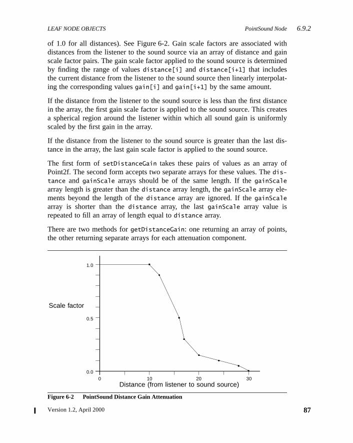
LEAF NODE OBJECTS PointSound Node6.9.2
withgainined
olat-
anceatesly
dis-
of
,
of 1.0 for all distances). See Figure 6-2. Gain scale factors are associateddistances from the listener to the sound source via an array of distance andscale factor pairs. The gain scale factor applied to the sound source is determby finding the range of valuesdistance[i] and distance[i+1] that includesthe current distance from the listener to the sound source then linearly interping the corresponding valuesgain[i] andgain[i+1] by the same amount.
If the distance from the listener to the sound source is less than the first distin the array, the first gain scale factor is applied to the sound source. This crea spherical region around the listener within which all sound gain is uniformscaled by the first gain in the array.
If the distance from the listener to the sound source is greater than the lasttance in the array, the last gain scale factor is applied to the sound source.
The first form ofsetDistanceGain takes these pairs of values as an arrayPoint2f. The second form accepts two separate arrays for these values. Thedis-
tance and gainScale arrays should be of the same length. If thegainScalearray length is greater than thedistance array length, thegainScale array ele-ments beyond the length of thedistance array are ignored. If thegainScalearray is shorter than thedistance array, the lastgainScale array value isrepeated to fill an array of length equal todistance array.
There are two methods forgetDistanceGain: one returning an array of pointsthe other returning separate arrays for each attenuation component.
Figure 6-2 PointSound Distance Gain Attenuation
Scale factor
Distance (from listener to sound source)
1.0
0.5
0.00 10 20 30
87Version 1.2, April 2000
6.9.3 ConeSound Node LEAF NODE OBJECTS
88
t ofainm-
be
list.
ts, adis-actortheould
in
rce isd bythe
on isoundtten-lter
of ae (infil-
foraxis)
ance
Distance elements in this array of Point2f are a monotonically increasing sefloating-point numbers measured from the location of the sound source. Gscale factor elements in this list of pairs can be any positive floating-point nubers. While for most applications this list of gain scale factors will usuallymonotonically decreasing, they do not have to be.
Figure 6-2 shows a graphical representation of a distance gain attenuationThe values given for distance/gain pairs would be
( (10.0, 1.0), (12.0, 0.9), (16.0, 0.5), (17.0, 0.3), (20.0, 0.16), (24.0, 0.12), (28.0, 0.05), (30.0, 0.0) )
Thus if the current distance from the listener to the sound source is 22 uniscale factor of 0.14 would be applied to the sound amplitude. If the currenttance from the listener to the sound source is less than 10 units, the scale fof 1.0 would be applied to the sound amplitude. If the current distance fromlistener to the sound source is greater than 30 units, the scale factor of 0.0 wbe applied to the sound amplitude.
The getDistanceGainLength method returns the length of the distance gaattenuation arrays. Arrays passed intogetDistanceGain methods should all beat least this size.
6.9.3 ConeSound Node
The ConeSound node object defines a PointSound node whose sound soudirected along a specific vector in space. A ConeSound source is attenuategain scale factors and filters based on the angle between the vector fromsource to the listener, and the ConeSound’s direction vector. This attenuatieither a single spherical distance gain attenuation (as for a general PointSsource) or dual front and back distance gain attenuations defining elliptical auation volumes. The angular filter and the active AuralAttribute component fidefine what filtering is applied to the sound source.
This node has the same attributes as a PointSound node, with the additiondirection vector and an array of points that each contain an angular distancradians), a gain scale factor, and a filter (which for now consists of a lowpasster cutoff frequency). Similar to the definition of the distance gain arrayPointSounds, a piecewise linear curve (defined in terms of radians from thespecifies the slope of these additional attenuation values.
Figure 6-3 shows an approximation of angular attenuation (disregarding distattenuation).
The Java 3D API Specification
LEAF NODE OBJECTS ConeSound Node6.9.3
thenode
ound
Figure 6-3 ConeSound
Constants
The ConeSound object contains the following flags:
public static final int ALLOW_DIRECTION_READpublic static final int ALLOW_DIRECTION_WRITEpublic static final int ALLOW_ANGULAR_ATTENUATION_READpublic static final int ALLOW_ANGULAR_ATTENUATION_WRITE
These flags, when enabled using thesetCapability method, allow an applica-tion to invoke methods that respectively read and write the direction andangular attenuation array. These capability flags are enforced only when theis part of a live or compiled scene graph.
Constructors
The ConeSound node object defines the following constructors:
public ConeSound()
Constructs a ConeSound node object that includes the defaults for a PointSobject plus the following defaults for its own fields:
DistanceGain[1]
angularAttenuation[3]
angularAttenuation[0]
Sound Direction (axis)
Attenuated Values
DistanceGain[0]
89Version 1.2, April 2000
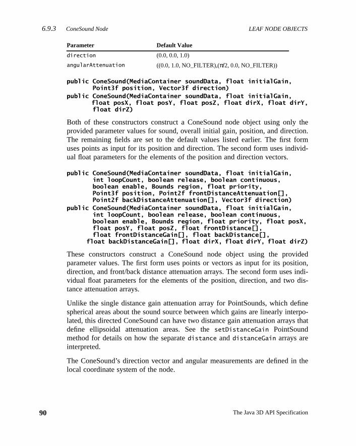
6.9.3 ConeSound Node LEAF NODE OBJECTS
90
theion.ormivid-
idedtion,indi-dis-
fineerpo-s that
in the
public ConeSound(MediaContainer soundData, float initialGain, Point3f position, Vector3f direction)public ConeSound(MediaContainer soundData, float initialGain,
float posX, float posY, float posZ, float dirX, float dirY, float dirZ)
Both of these constructors construct a ConeSound node object using onlyprovided parameter values for sound, overall initial gain, position, and directThe remaining fields are set to the default values listed earlier. The first fuses points as input for its position and direction. The second form uses indual float parameters for the elements of the position and direction vectors.
public ConeSound(MediaContainer soundData, float initialGain, int loopCount, boolean release, boolean continuous, boolean enable, Bounds region, float priority, Point3f position, Point2f frontDistanceAttenuation[], Point2f backDistanceAttenuation[], Vector3f direction)public ConeSound(MediaContainer soundData, float initialGain, int loopCount, boolean release, boolean continuous, boolean enable, Bounds region, float priority, float posX, float posY, float posZ, float frontDistance[], float frontDistanceGain[], float backDistance[],
float backDistanceGain[], float dirX, float dirY, float dirZ)
These constructors construct a ConeSound node object using the provparameter values. The first form uses points or vectors as input for its posidirection, and front/back distance attenuation arrays. The second form usesvidual float parameters for the elements of the position, direction, and twotance attenuation arrays.
Unlike the single distance gain attenuation array for PointSounds, which despherical areas about the sound source between which gains are linearly intlated, this directed ConeSound can have two distance gain attenuation arraydefine ellipsoidal attenuation areas. See thesetDistanceGain PointSoundmethod for details on how the separatedistance anddistanceGain arrays areinterpreted.
The ConeSound’s direction vector and angular measurements are definedlocal coordinate system of the node.
Parameter Default Value
direction (0.0, 0.0, 1.0)
angularAttenuation ((0.0, 1.0, NO_FILTER),(π/2, 0.0, NO_FILTER))
The Java 3D API Specification
LEAF NODE OBJECTS ConeSound Node6.9.3
idedrray.gle
tion,
ular
ntly
factortance,
public ConeSound(MediaContainer soundData, float initialGain, int loopCount, boolean release, boolean continuous, boolean enable, Bounds region, float priority, Point3f position, Point2f distanceAttenuation[], Vector3f direction, Point3f angularAttenuation[])public ConeSound(MediaContainer soundData, float initialGain, int loopCount, boolean release, boolean continuous, boolean enable, Bounds region, float priority, float posX, float posY, float posZ, float distance[], float distanceGain[], float dirX, float dirY, float dirZ,
float angle[], float angularGain[], float frequencyCutoff[])
These constructors construct a ConeSound node object using the provparameter values, which include a single spherical distance attenuation aThe first form uses points and vectors as input for its position, direction, sinspherical distanceAttenuation array, andangularAttenuation array. Thesecond form uses individual float parameters for the elements of the posidirection,distanceAttenuation array, andangularAttenuation array.
The first form accepts arrays of points for the distance attenuation and angvalues. Each Point2f in thedistanceAttenuation array contains a distance anda gain scale factor. Each Point3f in theangularAttenuation array contains anangular distance, a gain scale factor, and a filtering value (which is curredefined as a simple cutoff frequency).
The second form accepts separate arrays for the distance and gain scalecomponents of distance attenuation, and separate arrays for the angular disangular gain, and filtering components of angular attenuation. See thesetDis-
tanceGain PointSound method for details on how the separatedistance anddistanceGain arrays are interpreted. See thesetAngularAttenuation Cone-Sound method for details on how the separateangularDistance, angularGain,andfilter arrays are interpreted.
public ConeSound(MediaContainer soundData, float initialGain, int loopCount, boolean release, boolean continuous, boolean enable, Bounds region, float priority, Point3f position, Point2f frontDistanceAttenuation[], Point2f backDistanceAttenuation[], Vector3f direction, Point3f angularAttenuation[])public ConeSound(MediaContainer soundData, float initialGain, int loopCount, boolean release, float priority, boolean continuous, boolean enable, Bounds region, float posX, float posY, float posZ, float frontDistance[], float frontDistanceGain[], float backDistance[],
float backDistanceGain[], float dirX, float dirY, float dirZ,float angle[], float angularGain[], float frequencyCutoff[])
91Version 1.2, April 2000
6.9.3 ConeSound Node LEAF NODE OBJECTS
92
idedlipti-inputivid-
ef-the
rrays.singy isback(see
cesncethet be
al
These constructors construct a ConeSound node object using the provparameter values, which include two distance attenuation arrays defining elcal distance attenuation regions. The first form uses points and vectors asfor its position, direction, and attenuation arrays. The second form uses indual float parameters for these same elements.
These two constructors differ from the previous two constructors only in the dinition of the two distinct front and back distance attenuation arrays. SeesetDistanceGain ConeSound method for details on how the separatedistance
and distanceGain arrays are interpreted. See thesetAngularAttenuationConeSound method for details on how the separateangularDistance, angular-Gain, andfilter arrays are interpreted.
Methods
The ConeSound node object defines the following methods:
public void setDistanceGain(Point2f frontAttenuation[], Point2f backAttenuation[])public void setDistanceGain(float frontDistance[], float frontGain[], float backDistance[], float backGain[])public void setBackDistanceGain(Point2f attenuation[])public void setBackDistanceGain(float distance[], float gain[])public void getDistanceGain(Point2f frontAttenuation[], Point2f backAttenuation[])public void getDistanceGain(float frontDistance[], float frontGain[], float backDistance[], float backGain[])
These methods set and retrieve the ConeSound’s two distance attenuation aIf these are not set, no distance gain attenuation is performed (equivalent to ua distance gain of 1.0 for all distances). If only one distance attenuation arraset, spherical attenuation is assumed (see Figure 6-4). If both a front anddistance attenuation are set, elliptical attenuation regions are definedFigure 6-5). Use the PointSoundsetDistanceGain method to set the front dis-tance attenuation array separately from the back distance attenuation array.
A front distance attenuation array defines monotonically increasing distanfrom the sound source origin along the position direction vector. A back distaattenuation array (if given) defines monotonically increasing distances fromsound source origin along the negative direction vector. The two arrays musof the same length. ThebackDistance[i] gain values must be less than or equto frontDistance[i] gain values.
The Java 3D API Specification
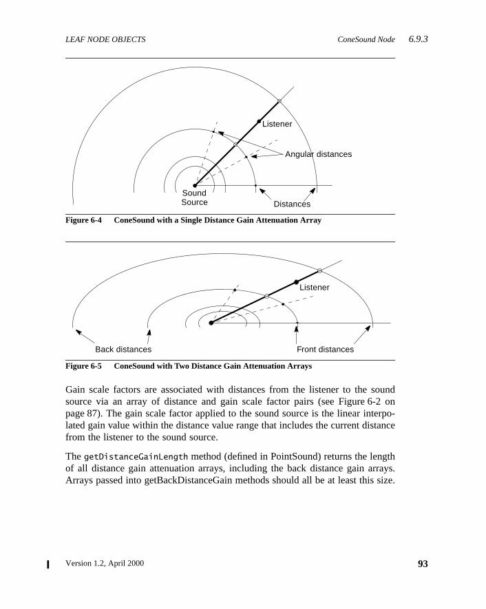
LEAF NODE OBJECTS ConeSound Node6.9.3
ound2 onrpo-
ance
thrays.size.
Figure 6-4 ConeSound with a Single Distance Gain Attenuation Array
Figure 6-5 ConeSound with Two Distance Gain Attenuation Arrays
Gain scale factors are associated with distances from the listener to the ssource via an array of distance and gain scale factor pairs (see Figure 6-page 87). The gain scale factor applied to the sound source is the linear intelated gain value within the distance value range that includes the current distfrom the listener to the sound source.
ThegetDistanceGainLength method (defined in PointSound) returns the lengof all distance gain attenuation arrays, including the back distance gain arArrays passed into getBackDistanceGain methods should all be at least this
Listener
Angular distances
DistancesSoundSource
Listener
Front distancesBack distances
93Version 1.2, April 2000
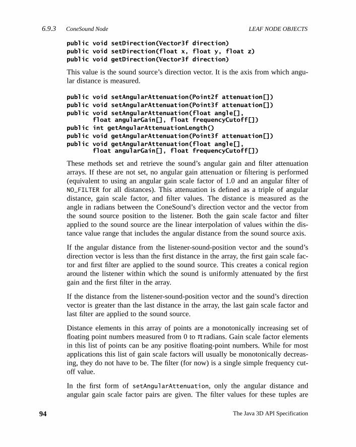
6.9.3 ConeSound Node LEAF NODE OBJECTS
94
gu-
ationmedr oflars thefromfilterdis-axis.
nd’sfac-gionrst
tionr and
t ofsst
as-ut-
are
public void setDirection(Vector3f direction)public void setDirection(float x, float y, float z)public void getDirection(Vector3f direction)
This value is the sound source’s direction vector. It is the axis from which anlar distance is measured.
public void setAngularAttenuation(Point2f attenuation[])public void setAngularAttenuation(Point3f attenuation[])public void setAngularAttenuation(float angle[], float angularGain[], float frequencyCutoff[])public int getAngularAttenuationLength()public void getAngularAttenuation(Point3f attenuation[])public void getAngularAttenuation(float angle[], float angularGain[], float frequencyCutoff[])
These methods set and retrieve the sound’s angular gain and filter attenuarrays. If these are not set, no angular gain attenuation or filtering is perfor(equivalent to using an angular gain scale factor of 1.0 and an angular filteNO_FILTER for all distances). This attenuation is defined as a triple of angudistance, gain scale factor, and filter values. The distance is measured aangle in radians between the ConeSound’s direction vector and the vectorthe sound source position to the listener. Both the gain scale factor andapplied to the sound source are the linear interpolation of values within thetance value range that includes the angular distance from the sound source
If the angular distance from the listener-sound-position vector and the soudirection vector is less than the first distance in the array, the first gain scaletor and first filter are applied to the sound source. This creates a conical rearound the listener within which the sound is uniformly attenuated by the figain and the first filter in the array.
If the distance from the listener-sound-position vector and the sound’s direcvector is greater than the last distance in the array, the last gain scale factolast filter are applied to the sound source.
Distance elements in this array of points are a monotonically increasing sefloating point numbers measured from 0 toπ radians. Gain scale factor elementin this list of points can be any positive floating-point numbers. While for moapplications this list of gain scale factors will usually be monotonically decreing, they do not have to be. The filter (for now) is a single simple frequency coff value.
In the first form of setAngularAttenuation, only the angular distance andangular gain scale factor pairs are given. The filter values for these tuples
The Java 3D API Specification
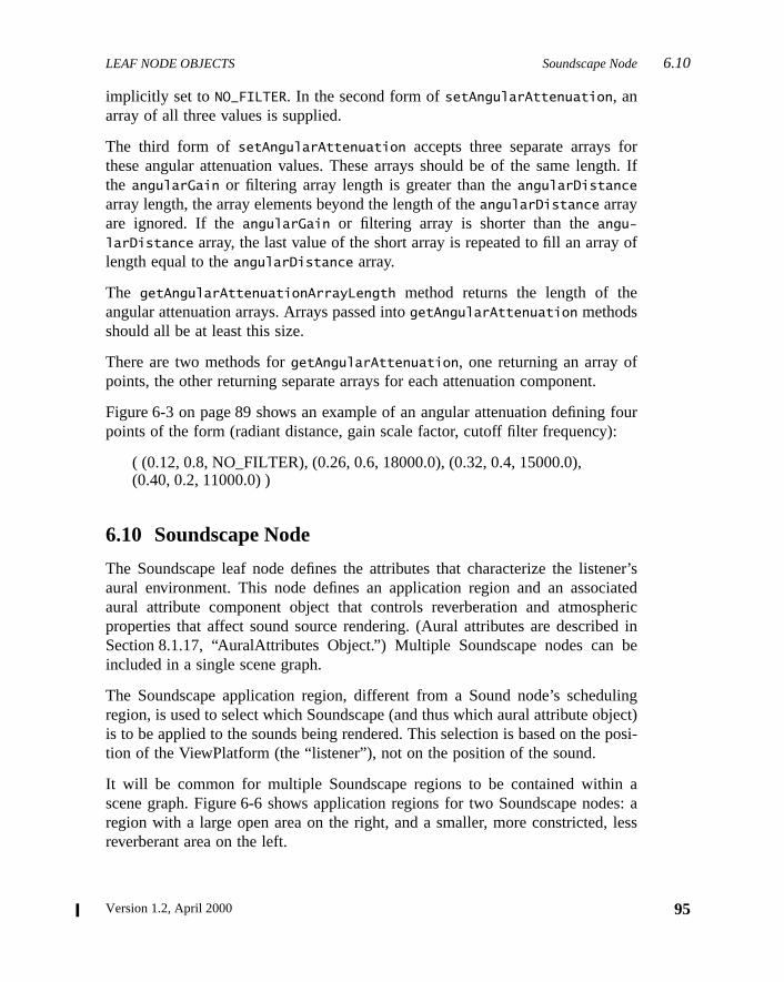
LEAF NODE OBJECTS Soundscape Node6.10
rgth. If
of
four
ner’siatedericd inbe
lingject)posi-
aes: aless
implicitly set toNO_FILTER. In the second form ofsetAngularAttenuation, anarray of all three values is supplied.
The third form of setAngularAttenuation accepts three separate arrays fothese angular attenuation values. These arrays should be of the same lenthe angularGain or filtering array length is greater than theangularDistancearray length, the array elements beyond the length of theangularDistance arrayare ignored. If theangularGain or filtering array is shorter than theangu-larDistance array, the last value of the short array is repeated to fill an arraylength equal to theangularDistance array.
The getAngularAttenuationArrayLength method returns the length of theangular attenuation arrays. Arrays passed intogetAngularAttenuation methodsshould all be at least this size.
There are two methods forgetAngularAttenuation, one returning an array ofpoints, the other returning separate arrays for each attenuation component.
Figure 6-3 on page 89 shows an example of an angular attenuation definingpoints of the form (radiant distance, gain scale factor, cutoff filter frequency):
( (0.12, 0.8, NO_FILTER), (0.26, 0.6, 18000.0), (0.32, 0.4, 15000.0),(0.40, 0.2, 11000.0) )
6.10 Soundscape Node
The Soundscape leaf node defines the attributes that characterize the listeaural environment. This node defines an application region and an assocaural attribute component object that controls reverberation and atmosphproperties that affect sound source rendering. (Aural attributes are describeSection 8.1.17, “AuralAttributes Object.”) Multiple Soundscape nodes canincluded in a single scene graph.
The Soundscape application region, different from a Sound node’s scheduregion, is used to select which Soundscape (and thus which aural attribute obis to be applied to the sounds being rendered. This selection is based on thetion of the ViewPlatform (the “listener”), not on the position of the sound.
It will be common for multiple Soundscape regions to be contained withinscene graph. Figure 6-6 shows application regions for two Soundscape nodregion with a large open area on the right, and a smaller, more constricted,reverberant area on the left.
95Version 1.2, April 2000
6.10 Soundscape Node LEAF NODE OBJECTS
96
theirg on
ande is
r its
Figure 6-6 Multiple Soundscape Application Regions
The reverberation attributes for these two regions could be set to representphysical differences so that active sounds are rendered differently dependinwhich region the listener is in.
Constants
The Soundscape node object defines the following flags:
public static final int ALLOW_APPLICATION_BOUNDS_READpublic static final int ALLOW_APPLICATION_BOUNDS_WRITEpublic static final int ALLOW_ATTRIBUTES_READpublic static final int ALLOW_ATTRIBUTES_WRITE
These flags, when enabled using thesetCapability method, allow an applica-tion to invoke methods that respectively read and write the application regionthe aural attributes. These capability flags are enforced only when the nodpart of a live or compiled scene graph.
Constructors
The Soundscape node object defines the following constructors:
public Soundscape()
Constructs a Soundscape node object that includes the following defaults foelements:
Application region 1 Application region 2
The Java 3D API Specification
LEAF NODE OBJECTS ViewPlatform Node 6.11
ation
unds.leafd tothe
und-
. Set-
y as int isir-
e the
public Soundscape(Bounds region, AuralAttributes attributes)
This method constructs a Soundscape node object using the specified applicregion and aural attributes.
Methods
The Soundscape node object defines the following methods:
public void setApplicationBounds(Bounds region)public Bounds getApplicationBounds()
These two methods access or modify the Soundscape node’s application boThis bounds is used as the application region when the application boundingis set tonull. The aural attributes associated with this Soundscape are userender the active sounds when this application region intersectsViewPlatform’s activation volume. ThegetApplicationBounds method returnsa copy of the associated bounds.
public void setApplicationBoundingLeaf(BoundingLeaf region)public BoundingLeaf getApplicationBoundingLeaf()
These two methods access or modify the Soundscape node’s application boing leaf. When set to a value other thannull, this bounding leaf overrides theapplication bounds object and is used as the application region.
public void setAuralAttributes(AuralAttributes attributes)public AuralAttributes getAuralAttributes()
These two methods access or modify the aural attributes of this Soundscapeting it to null results in default attribute use.
6.11 ViewPlatform Node
The ViewPlatform node object defines a viewing platform that is referenced bView object. The location, orientation, and scale of the composite transformthe scene graph from the root to the ViewPlatform specify where the viewpoinlocated and in which direction it is pointing. A viewer navigates through the vtual universe by changing the transform in the scene graph hierarchy abovViewPlatform.
Parameter Default Value
applicationBounds null (no active region)
auralAttributes null (uses default aural attributes)
97Version 1.2, April 2000
6.11 ViewPlatform Node LEAF NODE OBJECTS
98
licy.om-
ult
f theandjects
r-et ofore
s the
ulingbe
Constants
The ViewPlatform node object defines the following flags:
public static final int ALLOW_POLICY_READpublic static final int ALLOW_POLICY_WRITE
These flags, when enabled using thesetCapability method, allow an applica-tion to invoke methods that respectively read and write the view attach poThese capability flags are enforced only when the node is part of a live or cpiled scene graph.
Constructors
public ViewPlatform()
Constructs and initializes a new ViewPlatform leaf node object with defaparameters:
Methods
The ViewPlatform node object defines the following methods:
public void setActivationRadius(float activationRadius)public float getActivationRadius()
The activation radius defines an activation volume surrounding the center oViewPlatform. This activation volume intersects with the scheduling regionsapplication regions of other leaf node objects to determine which of those obmay affect rendering.
Different leaf objects interact with the ViewPlatform’s activation volume diffeently. The Background, Clip, and Soundscape leaf objects each define a sattributes and an application region in which those attributes are applied. If mthan one node of a given type (Background, Clip, or Soundscape) intersectViewPlatform’s activation volume, the “most appropriate” node is selected.
Sound leaf objects begin playing their associated sounds when their schedregion intersects a ViewPlatform’s activation volume. Multiple sounds mayactive at the same time.
Parameter Default Value
viewAttachPolicy View.NOMINAL_HEAD
activationRadius 62
The Java 3D API Specification
LEAF NODE OBJECTS Morph Node 6.13
dul-atesan10,
eyefor
t runhav-lassesser.
me-y ofodeeome-e
Behavior objects act somewhat differently. Those Behavior objects with scheing regions that intersect a ViewPlatform’s activation volume become candidfor scheduling. Effectively, a ViewPlatform’s activation volume becomesadditional qualifier on the scheduling of all Behavior objects. See Chapter“Behaviors and Interpolators,” for more details.
public void setViewAttachPolicy(int policy)public int getViewAttachPolicy()
The view attach policy determines how Java 3D places the user’s virtualpoint as a function of head position. See Section 9.4.3, “View Attach Policy,”details.
6.12 Behavior Node
The Behavior leaf node allows an application to manipulate a scene graph atime. Behavior is an abstract class that defines properties common to all Beior objects in Java 3D. There are several predefined behaviors that are subcof Behavior. Additionally, a Behavior leaf node may be subclassed by the uBehaviors are described in Chapter 10, “Behaviors and Interpolators.”
6.13 Morph Node
The Morph leaf node permits an application to morph between multiple GeotryArrays. The Morph node contains a single Appearance node, an arraGeometryArray objects, and an array of corresponding weights. The Morph ncombines these GeometryArrays into an aggregate shape based on each GtryArray’s corresponding weight. Typically, Behavior nodes will modify thweights to achieve various morphing effects.
Constants
The Morph node specifies the following flags:
public static final int ALLOW_GEOMETRY_ARRAY_READpublic static final int ALLOW_GEOMETRY_ARRAY_WRITEpublic static final int ALLOW_APPEARANCE_READpublic static final int ALLOW_APPEARANCE_WRITEpublic static final int ALLOW_WEIGHTS_READpublic static final int ALLOW_WEIGHTS_WRITEpublic static final int ALLOW_COLLISION_BOUNDS_READpublic static final int ALLOW_COLLISION_BOUNDS_WRITE
99Version 1.2, April 2000
6.13 Morph Node LEAF NODE OBJECTS
100
ofrance
of
rance
off theays
r
achates.e
New in 1.2New in 1.2
public static final int ALLOW_APPEARANCE_OVERRIDE_READpublic static final int ALLOW_APPEARANCE_OVERRIDE_WRITE
These flags, when enabled using thesetCapability method, allow an applica-tion to invoke methods that respectively read and write the node’s arrayGeometryArray objects, appearance, weights, collision Bounds, and appeaoverride enable components.
Constructors
The Morph node specifies the following constructors:
public Morph(GeometryArray geometryArrays[])
Constructs and initializes a new Morph leaf node with the specified arrayGeometryArray objects. Default values are used for all other parameters:
A null appearance object specifies that default values are used for all appeaattributes.
public Morph(GeometryArray geometryArrays[], Appearance appearance)
Constructs and initializes a new Morph leaf node with the specified arrayGeometryArray objects and the specified Appearance object. The length ogeometryArrays parameter determines the number of weighted geometry arrin this Morph node. IfgeometryArrays is null, then aNullPointerExceptionis thrown. If the Appearance component isnull, then default values are used foall appearance attributes.
Methods
The Morph node specifies the following methods:
public void setGeometryArrays(GeometryArray geometryArrays[])
This method sets the array of GeometryArray objects in the Morph node. EGeometryArray component specifies colors, normals, and texture coordinThe length of thegeometryArrays parameter must be equal to the length of th
Parameter Default Value
appearance null
weights [1, 0, 0, 0, ...]
collisionBounds null
appearanceOverrideEnable false
The Java 3D API Specification
LEAF NODE OBJECTS Morph Node 6.13
node.ent,
thisby
e
path
pear-errid-
5,
ew in 1.2
ew in 1.2
array with which this Morph node was created; otherwise, anIllegal-
ArgumentException is thrown.
public GeometryArray getGeometryArray(int index)
This method retrieves a single geometry array from the Morph node. Theindex
parameter specifies which array is returned.
public void setAppearance(Appearance appearance)public Appearance getAppearance()
These methods set and retrieve the Appearance component of this MorphThe Appearance component specifies material, texture, texture environmtransparency, or other rendering parameters. Setting it tonull results in defaultattribute use.
public void setWeights(double weights[])public double[] getWeights()
These methods set and retrieve the morph weight vector component ofMorph node. The Morph node “weights” the corresponding GeometryArraythe amount specified. The length of theweights parameter must be equal to thlength of the array with which this Morph node was created; otherwise, anIlle-
galArgumentException is thrown.
public void setCollisionBounds(Bounds bounds)public Bounds getCollisionBounds()
These methods set and retrieve the collision bounding object of this node.
public boolean intersect(SceneGraphPath path, PickShape pickShape)public boolean intersect(SceneGraphPath path, PickRay pickRay, double[] dist)
These methods check if the geometry component of this morph node underintersects with the pickShape.
public void setAppearanceOverrideEnable(boolean flag)public boolean getAppearanceOverrideEnable()
These methods set and retrieve the flag that indicates whether this node’s apance can be overridden. If the flag is true, this node’s appearance may be ovden by an AlternateAppearance leaf node, regardless of the value of theALLOW_
APPEARANCE_WRITE capability bit. The default value is false. See Section 6.1“AlternateAppearance Node.”
N
N
101Version 1.2, April 2000
6.14 Link Node LEAF NODE OBJECTS
102
oteder of“Link
om-nd aer-hier-then ofnon-ected
idingteAp-theiras noo be
thes that, butsen.
New in 1.2
New in 1.2
New in 1.2
New in 1.2
New in 1.2
New in 1.2
6.14 Link Node
The Link leaf node allows an application to reference a shared subgroup, roby a SharedGroup node, from within a branch of the scene graph. Any numbLink nodes can refer to the same SharedGroup node. See Section 7.1.2,Leaf Node,” for a description of this node.
6.15 AlternateAppearance Node
The AlternateAppearance leaf node is used for overriding the Appearance cponent of selected nodes. It defines an Appearance component object aregion of influence in which this AlternateAppearance node is active. An AltnateAppearance node also contains a list of Group nodes that specifies thearchical scope of this AlternateAppearance. If the scope list is empty,AlternateAppearance node has universe scope; all nodes within the regioinfluence are affected by this AlternateAppearance node. If the scope list isempty, only those Leaf nodes under the Group nodes in the scope list are affby this AlternateAppearance node (subject to the influencing bounds).
An AlternateAppearance node affects Shape3D and Morph nodes by overrtheir appearance component with the appearance component in this Alternapearance node. Only those Shape3D and Morph nodes that explicitly allowappearance to be overridden are affected. The AlternateAppearance node heffect on Shape3D and Morph nodes that do not allow their appearance toverridden.
If the regions of influence of multiple AlternateAppearance nodes overlap,Java 3D system will choose a single alternate appearance for those objectlie in the intersection. This is done in an implementation-dependent mannerin general, the AlternateAppearance node that is “closest” to the object is cho
Constants
The AlternateAppearance node specifies the following flags:
public static final int ALLOW_INFLUENCING_BOUNDS_READpublic static final int ALLOW_INFLUENCING_BOUNDS_WRITEpublic static final int ALLOW_APPEARANCE_READpublic static final int ALLOW_APPEARANCE_WRITEpublic static final int ALLOW_SCOPE_READpublic static final int ALLOW_SCOPE_WRITE
The Java 3D API Specification
LEAF NODE OBJECTS AlternateAppearance Node6.15
ingnfor-
fault
node.nodes
on toet to
ew in 1.2
ew in 1.2
ew in 1.2
ew in 1.2
ew in 1.2
ew in 1.2
ew in 1.2
ew in 1.2
These flags, when enabled using thesetCapability method, allow an applica-tion to invoke methods that respectively read and write the node’s influencbounds and bounds leaf information, appearance information, and scope imation components.
Constructors
The AlternateAppearance node specifies the following constructors:
public AlternateAppearance()
Constructs an AlternateAppearance node with default parameters. The devalues are as follows:
public AlternateAppearance(Appearance appearance)
Constructs an AlternateAppearance node with the specified appearance.
Methods
The AlternateAppearance node specifies the following methods:
public void setAppearance(Appearance appearance)public Appearance getAppearance()
These methods set and retrieve the appearance of this AlternateAppearanceThis appearance overrides the appearance in those Shape3D and Morphaffected by this AlternateAppearance node.
public void setInfluencingBounds(Bounds region)public Bounds getInfluencingBounds()
These methods set and retrieve the AlternateAppearance’s influencing regithe specified bounds. This is used when the influencing bounding leaf is snull.
public void setInfluencingBoundingLeaf(BoundingLeaf region)public BoundingLeaf getInfluencingBoundingLeaf()
Parameter Default Value
appearance null
scope empty (universe scope)
influencingBounds null
influencingBoundingLeaf null
N
N
N
N
N
N
N
N
103Version 1.2, April 2000
6.15 AlternateAppearance Node LEAF NODE OBJECTS
104
on toides
ear-thodnce
ly bydes
ncenodethisranceted
arether
t of
ancely bydes
s listAp-e are
New in 1.2
New in 1.2
New in 1.2
New in 1.2
New in 1.2
New in 1.2
New in 1.2
These methods set and retrieve the AlternateAppearance’s influencing regithe specified bounding leaf. When set to a value other than null, this overrthe influencing bounds object.
public void setScope(Group scope, int index)public Group getScope(int index)
The first method replaces the node at the specified index in this AlternateAppance node’s list of scopes with the specified Group node. The second meretrieves the Group node at the specified index from this AlternateAppearanode’s list of scopes. By default, AlternateAppearance nodes are scoped ontheir influencing bounds. This allows them to be scoped further by a list of noin the hierarchy.
public void insertScope(Group scope, int index)public void removeScope(int index)
The first method inserts the specified Group node into this AlternateAppearanode’s list of scopes at the specified index. The second method removes theat the specified index from this AlternateAppearance node’s list of scopes. Ifoperation causes the list of scopes to become empty, this AlternateAppeawill have universe scope; all nodes within the region of influence will be affecby this AlternateAppearance node. By default, AlternateAppearance nodesscoped only by their influencing bounds. This allows them to be scoped furby a list of nodes in the hierarchy.
public Enumeration getAllScopes()
This method returns an enumeration of this AlternateAppearance node’s lisscopes.
public void addScope(Group scope)
This method appends the specified Group node to this AlternateAppearnode’s list of scopes. By default, AlternateAppearance nodes are scoped ontheir influencing bounds. This allows them to be scoped further by a list of noin the hierarchy.
public int numScopes()
This method returns the number of nodes in this AlternateAppearance node’of scopes. If this number is 0, the list of scopes is empty and this Alternatepearance node has universe scope; all nodes within the region of influencaffected by this AlternateAppearance node.
The Java 3D API Specification
Version 1.2, April 2000
C H A P T E R 7
ss-raph.still
e firstto thein one
eneiatedd sub-rpo-
(see
nyraph
oup
Reusing Scene Graph
JAVA 3D provides application programmers with two different means for reuing scene graphs. First, multiple scene graphs can share a common subgSecond, the node hierarchy of a common subgraph can be cloned, whilesharing large component objects such as geometry and texture objects. In thcase, changes in the shared subgraph affect all scene graphs that refershared subgraph. In the second case, each instance is unique—a changeinstance does not affect any other instance.
7.1 Sharing Subgraphs
An application that wishes to share a subgraph from multiple places in a scgraph must do so through the use of the Link leaf node and an assocSharedGroup node. The SharedGroup node serves as the root of the sharegraph. The Link leaf node refers to the SharedGroup node. It does not incorate the shared scene graph directly into its scene graph.
7.1.1 SharedGroup Node
A SharedGroup node allows multiple Link leaf nodes to share its subgraphFigure 7-1) according to the following semantics:
• A SharedGroup may be referenced by one or more Link leaf nodes. Aruntime changes to a node or component object in this shared subgaffect all graphs that refer to this subgraph.
• A SharedGroup may be compiled by calling itscompile method prior tobeing referenced by any Link leaf nodes.
• Only Link leaf nodes may refer to SharedGroup nodes. A SharedGrnode cannot have parents or be attached to a Locale.
105
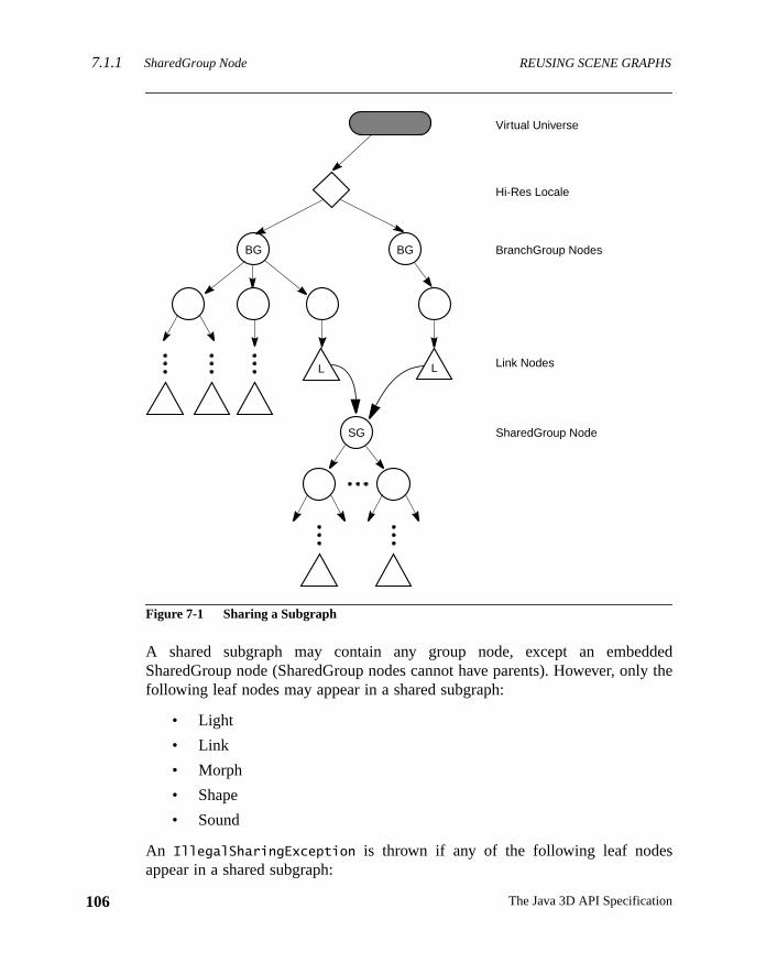
7.1.1 SharedGroup Node REUSING SCENE GRAPHS
106
ddedly the
Figure 7-1 Sharing a Subgraph
A shared subgraph may contain any group node, except an embeSharedGroup node (SharedGroup nodes cannot have parents). However, onfollowing leaf nodes may appear in a shared subgraph:
• Light
• Link
• Morph
• Shape
• Sound
An IllegalSharingException is thrown if any of the following leaf nodesappear in a shared subgraph:
BG
Virtual Universe
Hi-Res Locale
BG
L
SG
Link Nodes
SharedGroup Node
BranchGroup Nodes
L
The Java 3D API Specification
REUSING SCENE GRAPHS Link Leaf Node7.1.2
t and
d by. Seeme
ode
• AlternateAppearance
• Background
• BoundingLeaf
• Behavior
• Clip
• Fog
• ModelClip
• Soundscape
• ViewPlatform
Constructors
public SharedGroup()
Constructs and initializes a new SharedGroup node object.
Methods
The SharedGroup node defines the following methods:
public void compile()
This method compiles the source SharedGroup associated with this objeccreates and caches a newly compiled scene graph.
7.1.2 Link Leaf Node
The Link leaf node allows an application to reference a shared graph, rootea SharedGroup node, from within a branch graph or another shared graphFigure 7-1 on page 106. Any number of Link nodes can refer to the saSharedGroup node.
Constants
The Link node object defines two flags.
public static final int ALLOW_SHARED_GROUP_READpublic static final int ALLOW_SHARED_GROUP_WRITE
These flags, when enabled using thesetCapability method, allow an applica-tion to invoke methods that respectively read and write the SharedGroup n
107Version 1.2, April 2000
7.2 Cloning Subgraphs REUSING SCENE GRAPHS
108
the
ats to
h this
om-ate ahe
, andtypeiouseachtance
nentthe
pointed to by this Link node. These capability flags are enforced only whennode is part of a live or compiled scene graph.
Constructors
The Link node object defines two constructors.
public Link()public Link(SharedGroup sharedGroup)
The first form constructs a Link node object that does not yet point toSharedGroup node. The second form constructs a Link node object that pointhe specified SharedGroup node.
Methods
The Link node object defines two methods.
public void setSharedGroup(SharedGroup sharedGroup)public SharedGroup getSharedGroup()
These methods access and modify the SharedGroup node associated witLink leaf node.
7.2 Cloning Subgraphs
An application developer may wish to reuse a common subgraph without cpletely sharing that subgraph. For example, the developer may wish to creparking lot scene consisting of multiple cars, each with a different color. Tdeveloper might define three basic types of cars, such as convertible, trucksedan. To create the parking lot scene, the application will instantiate eachof car several times. Then the application can change the color of the varinstances to create more variety in the scene. Unlike shared subgraphs,instance is a separate copy of the scene graph definition: Changes to one insdo not affect any other instance.
Java 3D provides thecloneTree method for this purpose. ThecloneTreemethod allows the programmer to change some attributes (NodeCompoobjects) in a scene graph, while at the same time sharing the majority ofscene graph data—the geometry.
The Java 3D API Specification
REUSING SCENE GRAPHS References to Node Component Objects7.2.1
eir.1,
a. Set-
-d on
ng
lingrth).nentleaf
g theode
theref-
tion
ew in 1.2
ew in 1.2
ew in 1.2
Methods
public Node cloneTree()public Node cloneTree(boolean forceDuplicate)public Node cloneTree(boolean forceDuplicate, boolean allowDanglingReferences)public Node cloneTree(NodeReferenceTable referenceTable)public Node cloneTree(NodeReferenceTable referenceTable, boolean forceDuplicate)public Node cloneTree(NodeReferenceTable referenceTable, boolean forceDuplicate, boolean allowDanglingReferences)
These methods start the cloning of the subgraph. The optionalforceDuplicate
parameter, when set totrue, causes leaf NodeComponent objects to ignore thduplicateOnCloneTree value and always be duplicated (see Section 7.2“References to Node Component Objects”). TheallowDanglingReferencesparameter, when set totrue, will permit the cloning of a subgraph even whendangling reference is generated (see Section 7.2.3, “Dangling References”)ting forceDuplicate andallowDanglingReferences to false is the equivalentof calling cloneTree without any parameters. This will result in NodeComponent objects being either duplicated or referenced in the cloned node, basetheir duplicateOnCloneTree value. A DanglingReferenceException will bethrown if a dangling reference is encountered.
When thecloneTree method is called on a node, that node is duplicated alowith its entire internal state. If the node is a Group node,cloneTree is thencalled on each of the node’s children.
ThecloneTree method cannot be called on a live or compiled scene graph.
7.2.1 References to Node Component Objects
WhencloneTree reaches a leaf node, there are two possible actions for handthe leaf node’s NodeComponent objects (such as Material, Texture, and so foFirst, the cloned leaf node can reference the original leaf node’s NodeCompoobject—the NodeComponent object itself is not duplicated. Since the clonednode shares the NodeComponent object with the original leaf node, changindata in the NodeComponent object will effect a change in both nodes. This mwould also be used for objects that are read-only at run time.
Alternatively, the NodeComponent object can be duplicated, in which casenew leaf node would reference the duplicated object. This mode allows dataerenced by the newly created leaf node to be modified without that modificaaffecting the original leaf node.
N
N
N
109Version 1.2, April 2000
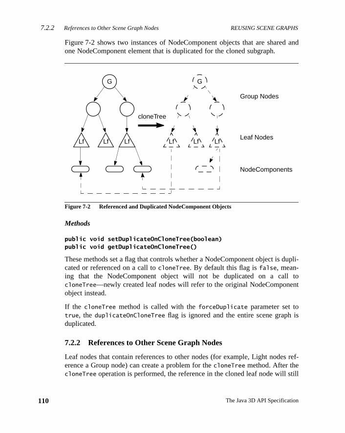
7.2.2 References to Other Scene Graph Nodes REUSING SCENE GRAPHS
110
and
upli-
tont
is
ref-
till
Figure 7-2 shows two instances of NodeComponent objects that are sharedone NodeComponent element that is duplicated for the cloned subgraph.
Figure 7-2 Referenced and Duplicated NodeComponent Objects
Methods
public void setDuplicateOnCloneTree(boolean)public void getDuplicateOnCloneTree()
These methods set a flag that controls whether a NodeComponent object is dcated or referenced on a call tocloneTree. By default this flag isfalse, mean-ing that the NodeComponent object will not be duplicated on a callcloneTree—newly created leaf nodes will refer to the original NodeComponeobject instead.
If the cloneTree method is called with theforceDuplicate parameter set totrue, the duplicateOnCloneTree flag is ignored and the entire scene graphduplicated.
7.2.2 References to Other Scene Graph Nodes
Leaf nodes that contain references to other nodes (for example, Light nodeserence a Group node) can create a problem for thecloneTree method. After thecloneTree operation is performed, the reference in the cloned leaf node will s
G
Leaf Nodes
Group Nodes
LfLfLf
NodeComponents
cloneTree
G
LfLfLf
The Java 3D API Specification
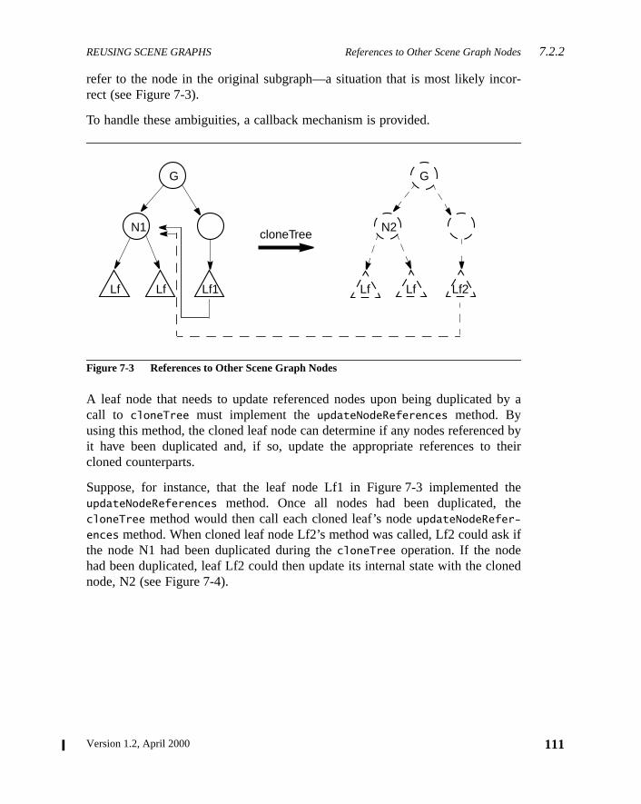
REUSING SCENE GRAPHS References to Other Scene Graph Nodes7.2.2
or-
by a
d bytheir
thehe
k if
ned
refer to the node in the original subgraph—a situation that is most likely increct (see Figure 7-3).
To handle these ambiguities, a callback mechanism is provided.
Figure 7-3 References to Other Scene Graph Nodes
A leaf node that needs to update referenced nodes upon being duplicatedcall to cloneTree must implement theupdateNodeReferences method. Byusing this method, the cloned leaf node can determine if any nodes referenceit have been duplicated and, if so, update the appropriate references tocloned counterparts.
Suppose, for instance, that the leaf node Lf1 in Figure 7-3 implementedupdateNodeReferences method. Once all nodes had been duplicated, tcloneTree method would then call each cloned leaf’s nodeupdateNodeRefer-
ences method. When cloned leaf node Lf2’s method was called, Lf2 could asthe node N1 had been duplicated during thecloneTree operation. If the nodehad been duplicated, leaf Lf2 could then update its internal state with the clonode, N2 (see Figure 7-4).
G G
cloneTreeN1 N2
Lf Lf Lf1 Lf Lf Lf2
111Version 1.2, April 2000
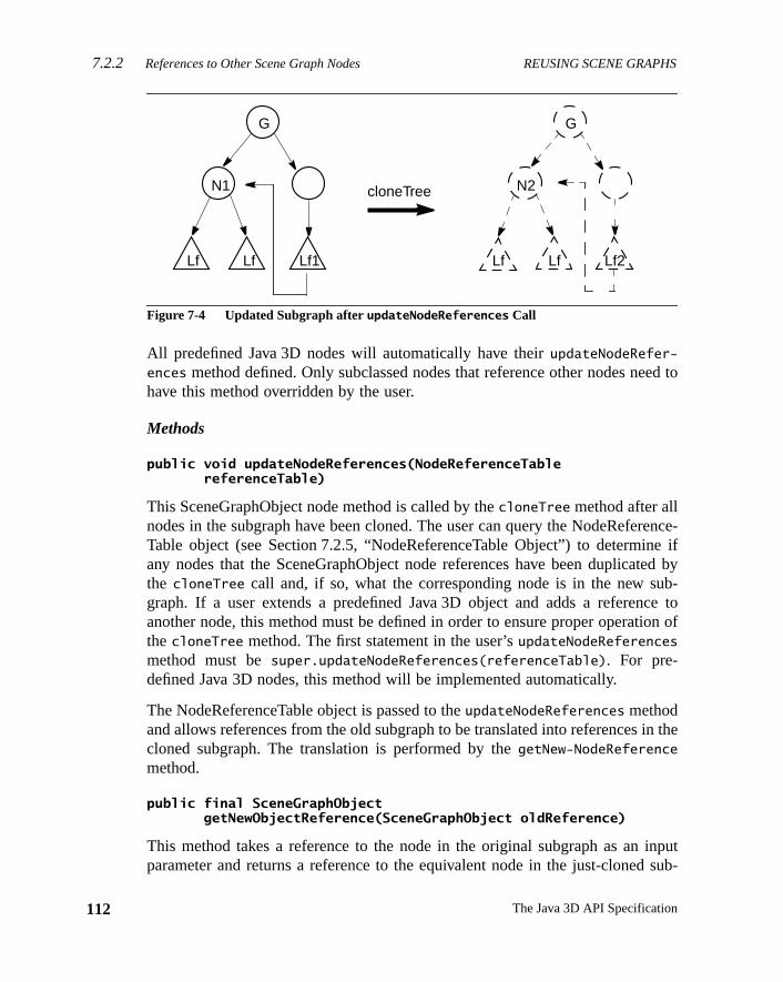
7.2.2 References to Other Scene Graph Nodes REUSING SCENE GRAPHS
112
ed to
rence-e if
ted byb-ce toon of
in the
inputsub-
Figure 7-4 Updated Subgraph afterupdateNodeReferences Call
All predefined Java 3D nodes will automatically have theirupdateNodeRefer-
ences method defined. Only subclassed nodes that reference other nodes nehave this method overridden by the user.
Methods
public void updateNodeReferences(NodeReferenceTable referenceTable)
This SceneGraphObject node method is called by thecloneTree method after allnodes in the subgraph have been cloned. The user can query the NodeRefeTable object (see Section 7.2.5, “NodeReferenceTable Object”) to determinany nodes that the SceneGraphObject node references have been duplicathe cloneTree call and, if so, what the corresponding node is in the new sugraph. If a user extends a predefined Java 3D object and adds a referenanother node, this method must be defined in order to ensure proper operatithecloneTree method. The first statement in the user’supdateNodeReferences
method must besuper.updateNodeReferences(referenceTable). For pre-defined Java 3D nodes, this method will be implemented automatically.
The NodeReferenceTable object is passed to theupdateNodeReferences methodand allows references from the old subgraph to be translated into referencescloned subgraph. The translation is performed by thegetNew-NodeReference
method.
public final SceneGraphObject getNewObjectReference(SceneGraphObject oldReference)
This method takes a reference to the node in the original subgraph as anparameter and returns a reference to the equivalent node in the just-cloned
Lf Lf Lf1
N1
G G
Lf Lf Lf2
N2cloneTree
The Java 3D API Specification
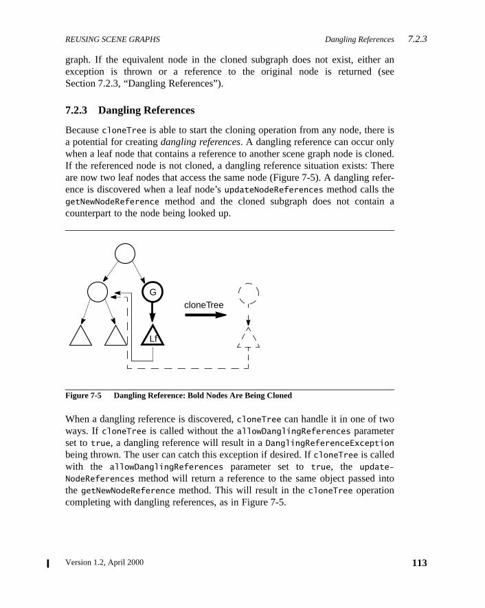
REUSING SCENE GRAPHS Dangling References7.2.3
r ansee
is
loned.hereefer-
a
nto
graph. If the equivalent node in the cloned subgraph does not exist, eitheexception is thrown or a reference to the original node is returned (Section 7.2.3, “Dangling References”).
7.2.3 Dangling References
BecausecloneTree is able to start the cloning operation from any node, therea potential for creatingdangling references. A dangling reference can occur onlywhen a leaf node that contains a reference to another scene graph node is cIf the referenced node is not cloned, a dangling reference situation exists: Tare now two leaf nodes that access the same node (Figure 7-5). A dangling rence is discovered when a leaf node’supdateNodeReferences method calls thegetNewNodeReference method and the cloned subgraph does not containcounterpart to the node being looked up.
Figure 7-5 Dangling Reference: Bold Nodes Are Being Cloned
When a dangling reference is discovered,cloneTree can handle it in one of twoways. If cloneTree is called without theallowDanglingReferences parameterset totrue, a dangling reference will result in aDanglingReferenceExceptionbeing thrown. The user can catch this exception if desired. IfcloneTree is calledwith the allowDanglingReferences parameter set totrue, the update-
NodeReferences method will return a reference to the same object passed ithe getNewNodeReference method. This will result in thecloneTree operationcompleting with dangling references, as in Figure 7-5.
G
Lf
cloneTree
113Version 1.2, April 2000
7.2.4 Subclassing Nodes REUSING SCENE GRAPHS
114
uto-sub-
st be
-spe-
define
s nec-
New in 1.2
7.2.4 Subclassing Nodes
All Java 3D predefined nodes (for example, Interpolators and LOD nodes) amatically handle all node reference and duplication operations. When a userclasses a Leaf object or a NodeComponent object, certain methods muprovided in order to ensure the proper operation ofcloneTree.
Leaf node subclasses (for example, Behaviors) that contain any user nodecific data that needs to be duplicated during acloneTree operation must definethe following two methods:
Node cloneNode(boolean forceDuplicate);void duplicateNode(Node n, boolean forceDuplicate)
ThecloneNode method consists of three lines:
UserSubClass usc = new UserSubClass();usc.duplicateNode(this, forceDuplicate);return usc;
TheduplicateNode method must first callsuper.duplicateNode before dupli-cating any necessary user-specific data or setting any user-specific state.
NodeComponent subclasses that contain any user node-specific data mustthe following two methods:
NodeComponent cloneNodeComponent();void duplicateNodeComponent(NodeComponent nc, boolean forceDuplicate);
ThecloneNodeComponent method consists of three lines:
UserNodeComponent unc = new UserNodeComponent();unc.duplicateNodeComponent(this, forceDuplicate);return un;
The duplicateNodeComponent must first callsuper.duplicateNodeComponentand then can duplicate any user-specific data or set any user-specific state aessary.
The Java 3D API Specification
REUSING SCENE GRAPHS Example User Behavior Node7.2.6
psThis
refer-3D.
inputsub-
r ansee
erly
ew in 1.2
7.2.5 NodeReferenceTable Object
The NodeReferenceTable object is used by a leaf node’supdateNodeReferences
method called by thecloneTree operation. The NodeReferenceTable manodes from the original subgraph to the new nodes in the cloned subgraph.information can than be used to update any cloned leaf node references toence nodes in the cloned subgraph. This object can be created only by Java
Constructors
public NodeReferenceTable()
Constructs an empty NodeReferenceTable.
Methods
public SceneGraphObject getNewObjectReference(SceneGraphObject oldReference)
This method takes a reference to the node in the original subgraph as anparameter and returns a reference to the equivalent node in the just-clonedgraph. If the equivalent node in the cloned subgraph does not exist, eitheexception is thrown or a reference to the original node is returned (Section 7.2.3, “Dangling References”).
7.2.6 Example User Behavior Node
The following is an example of a user-defined Behavior object to show prophow to define a node to be compatible with thecloneTree operation.
class RotationBehavior extends Behavior {TransformGroup objectTransform;WakeupOnElapsedFrames w;
Matrix4d rotMat = new Matrix4d();Matrix4d objectMat = new Matrix4d();Transform3D t = new Transform3D();
// Override Behavior's initialize method to set up wakeup// criteriapublic void initialize() {
// Establish initial wakeup criteriawakeupOn(w);
}
N
115Version 1.2, April 2000
7.2.6 Example User Behavior Node REUSING SCENE GRAPHS
116
// Override Behavior's stimulus method to handle the eventpublic void processStimulus(Enumeration criteria) {
// Rotate by another PI/120.0 radiansobjectMat.mul(objectMat, rotMat);t.set(objectMat);objectTransform.setTransform(t);
// Set wakeup criteria for next timewakeupOn(w);
}
// Constructor for rotation behavior.public RotationBehavior(TransformGroup tg, int numFrames) {
w = new WakeupOnElapsedFrames(numFrames);objectTransform = tg;objectMat.setIdentity();
// Create a rotation matrix that rotates PI/120.0// radians per framerotMat.rotX(Math.PI/120.0);
// Note: When this object is duplicated via cloneTree,// the cloned RotationBehavior node needs to point to// the TransformGroup in the just-cloned tree.
}
// Sets a new TransformGroup.public void setTransformGroup(TransformGroup tg) {
objectTransform = tg;}
// The next two methods are needed for cloneTree to operate// correctly.// cloneNode is needed to provide a new instance of the user// derived subclass.public Node cloneNode(boolean forceDuplicate) {
// Get all data from current node needed for// the constructorint numFrames = w.getElapsedFrameCount();
The Java 3D API Specification
REUSING SCENE GRAPHS Example User Behavior Node7.2.6
RotationBehavior r =new RotationBehavior(objectTransform, numFrames);
r.duplicateNode(this, forceDuplicate);return r;
}// duplicateNode is needed to duplicate all super class// data as well as all user data.public void duplicateNode(Node originalNode, boolean forceDuplicate) {
super.duplicateNode(originalNode, forceDuplicate);// Nothing to do here - all unique data was handled// in the constructor in the cloneNode routine.
}
// duplicateNode is needed to duplicate all super class// data as well as all user data.public void duplicateNode(Node originalNode, boolean forceDuplicate) {
super.duplicateNode(originalNode, forceDuplicate);// Nothing to do here - all unique data was handled// in the constructor in the cloneNode routine.
}
// Callback for when this leaf is cloned. For this object// we want to find the cloned TransformGroup node that this// clone Leaf node should reference.public void updateNodeReferences(NodeReferenceTable t) {
super.updateNodeReferences(t);
// Update node's TransformGroup to proper referenceTransformGroup newTg = (TransformGroup)t.getNewObjectReference(
objectTransform);setTransformGroup(newTg);
}}
117Version 1.2, April 2000

Version 1.2, April 2000
C H A P T E R 8
tsnce
con-a-
alue.plex
te
g a10.6,
es allin ae
Node Component Objec
NODE component objects include the actual geometry and appearaattributes used to render the geometry.
8.1 Node Component Objects: Attributes
Node objects by themselves do not fully specify their exact semantics. Theytain information that further refines their exact meaning. Some of that informtion is specified as an attribute and an associated floating-point or integer vIn many cases, however, the information consists of references to more comentities callednode component objects. Node component objects encapsularelated state information in a single entity. See Figure 8-1.
8.1.1 Alpha Object
The Alpha node component object provides common methods for convertintime value into an alpha value (a value in the range 0.0 to 1.0). See Section“Interpolator Behaviors,” for a description of the Alpha object.
8.1.2 Appearance Object
The Appearance object is a component object of a Shape3D node that definrendering state attributes for that shape node. If the Appearance objectShape3D node isnull, default values will be used for all rendering statattributes.
Constants
The Appearance component object defines the following flags:
119
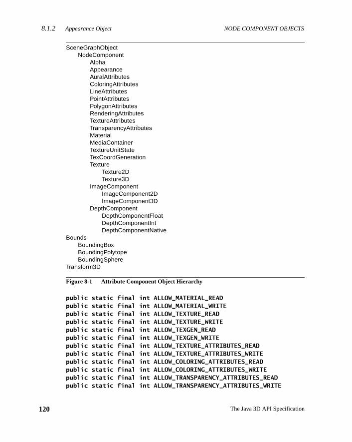
8.1.2 Appearance Object NODE COMPONENT OBJECTS
120
Figure 8-1 Attribute Component Object Hierarchy
public static final int ALLOW_MATERIAL_READpublic static final int ALLOW_MATERIAL_WRITEpublic static final int ALLOW_TEXTURE_READpublic static final int ALLOW_TEXTURE_WRITEpublic static final int ALLOW_TEXGEN_READpublic static final int ALLOW_TEXGEN_WRITEpublic static final int ALLOW_TEXTURE_ATTRIBUTES_READpublic static final int ALLOW_TEXTURE_ATTRIBUTES_WRITEpublic static final int ALLOW_COLORING_ATTRIBUTES_READpublic static final int ALLOW_COLORING_ATTRIBUTES_WRITEpublic static final int ALLOW_TRANSPARENCY_ATTRIBUTES_READpublic static final int ALLOW_TRANSPARENCY_ATTRIBUTES_WRITE
SceneGraphObjectNodeComponent
AlphaAppearanceAuralAttributesColoringAttributesLineAttributesPointAttributesPolygonAttributesRenderingAttributesTextureAttributesTransparencyAttributesMaterialMediaContainerTextureUnitStateTexCoordGenerationTexture
Texture2DTexture3D
ImageComponentImageComponent2DImageComponent3D
DepthComponentDepthComponentFloatDepthComponentIntDepthComponentNative
BoundsBoundingBoxBoundingPolytopeBoundingSphere
Transform3D
The Java 3D API Specification
NODE COMPONENT OBJECTS Appearance Object8.1.2
fer-heseled
vari-
ing.
. Set-al
tion)will
ew in 1.2
ew in 1.2
public static final int ALLOW_RENDERING_ATTRIBUTES_READpublic static final int ALLOW_RENDERING_ATTRIBUTES_WRITEpublic static final int ALLOW_POLYGON_ATTRIBUTES_READpublic static final int ALLOW_POLYGON_ATTRIBUTES_WRITEpublic static final int ALLOW_LINE_ATTRIBUTES_READpublic static final int ALLOW_LINE_ATTRIBUTES_WRITEpublic static final int ALLOW_POINT_ATTRIBUTES_READpublic static final int ALLOW_POINT_ATTRIBUTES_WRITEpublic static final int ALLOW_TEXTURE_UNIT_STATE_READpublic static final int ALLOW_TEXTURE_UNIT_STATE_WRITE
These flags, when enabled using thesetCapability method, allow an applica-tion to invoke methods that read and write the specified component object reence (material, texture, texture coordinate generation, and so forth). Tcapability flags are enforced only when the object is part of a live or compiscene graph.
Constructors
The Appearance object has the following constructor:
public Appearance()
Constructs and initializes an Appearance object using defaults for all stateables. All component object references are initialized to null.
Methods
The Appearance object has the following methods:
public void setMaterial(Material material)public Material getMaterial()
The Material object specifies the desired material properties used for lightSetting it tonull disables lighting.
public void setTexture(Texture texture)public Texture getTexture()
The Texture object specifies the desired texture map and texture parametersting it to null disables texture mapping. Applications must not set individutexture component objects (texture, textureAttributes, or texCoordGeneraand the texture unit state array in the same Appearance object. Doing soresult in an exception being thrown.
N
N
121Version 1.2, April 2000
8.1.2 Appearance Object NODE COMPONENT OBJECTS
122
m-tex-an
it to
public void setTextureAttributes(TextureAttributes textureAttributes)public TextureAttributes getTextureAttributes()
These methods set and retrieve the TextureAttributes object. Setting it tonull
results in default attribute use. Applications must not set individual texture coponent objects (texture, textureAttributes, or texCoordGeneration) and theture unit state array in the same Appearance object. Doing so will result inexception being thrown.
public void setColoringAttributes(ColoringAttributes coloringAttributes)public ColoringAttributes getColoringAttributes()
These methods set and retrieve the ColoringAttributes object. Setting it tonull
results in default attribute use.
public void setTransparencyAttributes( TransparencyAttributes transparencyAttributes)public TransparencyAttributes getTransparencyAttributes()
These methods set and retrieve the TransparencyAttributes object. Settingnull results in default attribute use.
public void setRenderingAttributes(RenderingAttributes renderingAttributes)public RenderingAttributes getRenderingAttributes()
These methods set and retrieve the RenderingAttributes object. Setting it tonull
results in default attribute use.
public void setPolygonAttributes(PolygonAttributes polygonAttributes)public PolygonAttributes getPolygonAttributes()
These methods set and retrieve the PolygonAttributes object. Setting it tonull
results in default attribute use.
public void setLineAttributes(LineAttributes lineAttributes)public LineAttributes getLineAttributes()
These methods set and retrieve the LineAttributes object. Setting it tonull
results in default attribute use.
public void setPointAttributes(PointAttributes pointAttributes)public PointAttributes getPointAttributes()
The Java 3D API Specification
NODE COMPONENT OBJECTS ColoringAttributes Object8.1.3
bjectturecesthere-thodturerre-Ar-ctstateeing
ear-tureof 0
ew in 1.2
ew in 1.2
ew in 1.2
ew in 1.2
ew in 1.2
These methods set and retrieve the PointAttributes object. Setting it tonull
results in default attribute use.
public void setTexCoordGeneration(TexCoordGeneration texCoordGeneration)public TexCoordGeneration getTexCoordGeneration()
These methods set and retrieve the TexCoordGeneration object. Setting it tonull
disables texture coordinate generation.
public void setTextureUnitState(TextureUnitState[] stateArray)public void setTextureUnitState(int index, TextureUnitState state)public TextureUnitState[] getTextureUnitState()public TextureUnitState getTextureUnitState(int index)
These methods set and retrieve the texture-unit state for this Appearance o(see Section 8.1.15, “TextureUnitState Object”). The first method sets the texunit state array to the specified array. A shallow copy of the array of referento the TextureUnitState objects is made. If the specified array is null or iflength of the array is 0, multitexture is disabled. Within the array, a null TextuUnitState element disables the corresponding texture unit. The second mesets the texture unit state array object at the specified index within the texunit state array to the specified object. If the specified object is null, the cosponding texture unit is disabled. The index must be within the range [0, stateray.length–1]. Applications must not set individual texture component obje(texture, textureAttributes, or texCoordGeneration) and the texture unit sarray in the same Appearance object. Doing so will result in an exception bthrown.
public int getTextureUnitCount()
This method retrieves the length of the texture unit state array from this Appance object. The length of this array specifies the maximum number of texunits that will be used by this appearance object. If the array is null, a countis returned.
8.1.3 ColoringAttributes Object
The ColoringAttributes object defines attributes that apply to color mapping.
N
N
N
N
N
123Version 1.2, April 2000
8.1.3 ColoringAttributes Object NODE COMPONENT OBJECTS
124
and
es.
om-d,lor.
ed in
om-
Constants
public static final int ALLOW_COLOR_READpublic static final int ALLOW_COLOR_WRITEpublic static final int ALLOW_SHADE_MODEL_READpublic static final int ALLOW_SHADE_MODEL_WRITE
These flags, when enabled using thesetCapability method, allow an applica-tion to invoke methods that respectively read and write its color componentshade model component information.
Constructors
public ColoringAttributes()
Constructs a ColoringAttributes node with default parameters:
public ColoringAttributes(Color3f color, int shadeModel)public ColoringAttributes(float red, float green, float blue, int shadeModel)
These constructors create a ColoringAttributes object with the specified valu
Methods
public void setColor(Color3f color)public void setColor(float r, float g, float b)public void getColor(Color3f color)
These methods set and retrieve the intrinsic color of this ColoringAttributes cponent object. This color is used only for unlit geometry. If lighting is enablethe material colors are used in the lighting equation to produce the final coWhen vertex colors are present in unlit geometry, those vertex colors are usplace of this ColoringAttributes color unless the vertex colors are ignored.
public void setShadeModel(int shadeModel)public int getShadeModel()
These methods set and retrieve the shade model for this ColoringAttributes cponent object. The shade model is one of the following:
• FASTEST: Uses the fastest available method for shading.
Parameter Default Value
color white (1,1,1)
shadeModel SHADE_GOURAUD
The Java 3D API Specification
NODE COMPONENT OBJECTS LineAttributes Object8.1.4
g.
ex
or-
ght
ne
ern
• NICEST: Uses the nicest (highest quality) available method for shadin
• SHADE_FLAT: Does not interpolate color across the primitive.
• SHADE_GOURAUD: Smoothly interpolates the color at each vertacross the primitive.
8.1.4 LineAttributes Object
The LineAttributes object defines attributes that apply to line primitives.
Constants
The LineAttributes object specifies the following variables:
public static final int ALLOW_WIDTH_READpublic static final int ALLOW_WIDTH_WRITEpublic static final int ALLOW_PATTERN_READpublic static final int ALLOW_PATTERN_WRITEpublic static final int ALLOW_ANTIALIASING_READpublic static final int ALLOW_ANTIALIASING_WRITE
These flags, when enabled using thesetCapability method, allow an applica-tion to invoke methods that read and write its individual component field infmation.
public static final int PATTERN_SOLID
Draws a solid line with no pattern.
public static final int PATTERN_DASH
Draws a dashed line. Ideally, this will be drawn with a repeating pattern of eipixels on and eight pixels off.
public static final int PATTERN_DOT
Draws a dotted line. Ideally, this will be drawn with a repeating pattern of opixel on and seven pixels off.
public static final int PATTERN_DASH_DOT
Draws a dashed-dotted line. Ideally, this will be drawn with a repeating pattof seven pixels on, four pixels off, one pixel on, and four pixels off.
125Version 1.2, April 2000
8.1.4 LineAttributes Object NODE COMPONENT OBJECTS
126
th a
rn,
ine-
At-
m-g.
New in 1.2
public static final int PATTERN_USER_DEFINEDDraws lines with a user-defined line pattern. The line pattern is specified wipattern mask and a scale factor.
Constructors
public LineAttributes()
Constructs a LineAttributes object with default parameters:
public LineAttributes(float lineWidth, int linePattern, boolean lineAntialiasing)
Constructs a LineAttributes object with specified values of line width, patteand whether antialiasing is enabled or disabled.
Methods
public void setLineWidth(float lineWidth)public float getLineWidth()
These methods respectively set and retrieve the line width, in pixels, for this LAttributes component object.
public void setLinePattern(int linePattern)public int getLinePattern()
These methods respectively set and retrieve the line pattern for this Linetributes component object. ThelinePattern value describes the line pattern tobe used, which is one of the following:PATTERN_SOLID, PATTERN_DASH,PATTERN_DOT, or PATTERN_DASH_DOT.
public void setLineAntialiasingEnable(boolean state)public boolean getLineAntialiasingEnable()
Theset method enables or disables line antialiasing for this LineAttributes coponent object. Theget method retrieves the state of the line antialiasing flaThe flag istrue if line antialiasing is enabled,false if line antialiasing is dis-abled.
Parameter Default Value
lineWidth 1
linePattern PATTERN_SOLID
lineAntialiasing false
The Java 3D API Specification
NODE COMPONENT OBJECTS PointAttributes Object8.1.5
pat-
d offe orheding
isatinges
. Itthe
e lineine-
manysk ofelsare
ew in 1.2ew in 1.2
ew in 1.2
ew in 1.2
public void setPatternMask(int mask)public int getPatternMask()
These methods respectively set and retrieve the line pattern mask. The linetern mask is used when the linePattern attribute is set toPATTERN_USER_
DEFINED.
In this mode, the pattern is specified using a 16-bit mask that specifies on ansegments. Bit 0 in the pattern mask corresponds to the first pixel of the linline strip primitive. A value of 1 for a bit in the pattern mask indicates that tcorresponding pixel is drawn, while a value of 0 indicates that the corresponpixel is not drawn. After all 16 bits in the pattern are used, the patternrepeated. For example, a mask of 0x00ff defines a dashed line with a repepattern of eight pixels on followed by eight pixels off. A value of 0x0101 defina dotted line with a repeating pattern of one pixel on and seven pixels off.
The pattern continues around individual line segments of a line strip primitiveis restarted at the beginning of each new line strip. For line array primitives,pattern is restarted at the beginning of each line.
public void setPatternScaleFactor(int scaleFactor)public int getPatternScaleFactor()
These methods respectively set and retrieve the line pattern scale factor. Thpattern scale factor is used in conjunction with the patternMask when the lPattern attribute is set toPATTERN_USER_DEFINED. The pattern is multiplied bythe scale factor such that each bit in the pattern mask corresponds to thatconsecutive pixels. For example, a scale factor of 3 applied to a pattern ma0x001f would produce a repeating pattern of 15 pixels on followed by 33 pixoff. The valid range for this attribute is [1,15]. Values outside this rangeclamped.
8.1.5 PointAttributes Object
The PointAttributes object defines attributes that apply to point primitives.
Constants
The PointAttributes object specifies the following variables:
public static final int ALLOW_SIZE_READpublic static final int ALLOW_SIZE_WRITE
NN
N
N
127Version 1.2, April 2000
8.1.6 PolygonAttributes Object NODE COMPONENT OBJECTS
128
or-
com-
tesg
es.
public static final int ALLOW_ANTIALIASING_READpublic static final int ALLOW_ANTIALIASING_WRITE
These flags, when enabled using thesetCapability method, allow an applica-tion to invoke methods that read and write its individual component field infmation.
Constructors
public PointAttributes()
Constructs a PointAttributes object with default parameters:
public PointAttributes(float pointSize, boolean pointAntialiasing)
Constructs a PointAttributes object with specified values.
Methods
public void setPointSize(float pointSize)public float getPointSize()
These methods set and retrieve the point size, in pixels, for this Appearanceponent object.
public void setPointAntialiasingEnable(boolean state)public boolean getPointAntialiasingEnable()
The set method enables or disables point antialiasing for this PointAttribucomponent object. Theget method retrieves the state of the point antialiasinflag. The flag istrue if point antialiasing is enabled;false if point antialiasingis disabled.
8.1.6 PolygonAttributes Object
The PolygonAttributes object defines attributes for rendering polygon primitiv
Constants
The PolygonAttributes object specifies the following variables:
Parameter Default Value
pointSize 1
pointAntialiasingEnable false
The Java 3D API Specification
NODE COMPONENT OBJECTS PolygonAttributes Object8.1.6
or-
val-
tes
ew in 1.2
public static final int ALLOW_CULL_FACE_READpublic static final int ALLOW_CULL_FACE_WRITEpublic static final int ALLOW_MODE_READpublic static final int ALLOW_MODE_WRITEpublic static final int ALLOW_OFFSET_READpublic static final int ALLOW_OFFSET_WRITEpublic static final int ALLOW_NORMAL_FLIP_READpublic static final int ALLOW_NORMAL_FLIP_WRITE
These flags, when enabled using thesetCapability method, allow an applica-tion to invoke methods that read and write its individual component field infmation.
Constructors
public PolygonAttributes()
Constructs a PolygonAttributes object with default parameters:
public PolygonAttributes(int polygonMode, int cullFace, float polygonOffset)public PolygonAttributes(int polygonMode, int cullFace, float polygonOffset, boolean backFaceNormalFlip)public PolygonAttributes(int polygonMode, int cullFace, float polygonOffset, boolean backFaceNormalFlip, float polygonOffsetFactor)
These constructors create a new PolygonAttributes object with the specifiedues.
Methods
public void setCullFace(int cullFace)public int getCullFace()
These methods set and retrieve the face culling flag for this PolygonAttribucomponent object. The face culling flag is one of the following:
Parameter Default Value
cullFace CULL_BACK
backFaceNormalFlip false
polygonMode POLYGON_FILL
polygonOffset 0.0
polygonOffsetFactor 0.0
N
129Version 1.2, April 2000
8.1.7 RenderingAttributes Object NODE COMPONENT OBJECTS
130
atested)ed,als.
ear-ing:
he
en
f
space
lied
all
New in 1.2
New in 1.2
• CULL_NONE: Performs no face culling.
• CULL_FRONT: Culls all front-facing polygons.
• CULL_BACK: Culls all back-facing polygons.
public void setBackFaceNormalFlip(boolean backFaceNormalFlip)public boolean getBackFaceNormalFlip()
These methods set and retrieve the back-face normal flip flag. This flag indicwhether vertex normals of back-facing polygons should be flipped (negaprior to lighting. When this flag is set to true and back-face culling is disablpolygons are rendered as if the polygon had two sides with opposing normThis feature is disabled by default.
public void setPolygonMode(int polygonMode)public int getPolygonMode()
These methods set and retrieve the polygon rasterization mode for this Appance component object. The polygon rasterization mode is one of the follow
• POLYGON_POINT: Renders polygonal primitives as points drawn at tvertices of the polygon.
• POLYGON_LINE: Renders polygonal primitives as lines drawn betweconsecutive vertices of the polygon.
• POLYGON_FILL: Renders polygonal primitives by filling the interior othe polygon.
public void setPolygonOffset(float polygonOffset)public float getPolygonOffset()
These methods set and retrieve the constant polygon offset. This screen-offset is added to the final, device coordinatez value of polygon primitives.
public void setPolygonOffsetFactor(float polygonOffsetFactor)public float getPolygonOffsetFactor()
These methods set and retrieve the polygon offset factor. This factor is multipby the slope of the polygon and then added to the final device coordinatez valueof polygon primitives.
8.1.7 RenderingAttributes Object
The RenderingAttributes object defines common rendering attributes forprimitive types.
The Java 3D API Specification
NODE COMPONENT OBJECTS RenderingAttributes Object8.1.7
lue
ew in 1.2
ew in 1.2
ew in 1.2
ew in 1.2
ew in 1.2
ew in 1.2
ew in 1.2
Constants
public static final int ALLOW_ALPHA_TEST_VALUE_READpublic static final int ALLOW_ALPHA_TEST_VALUE_WRITEpublic static final int ALLOW_ALPHA_TEST_FUNCTION_READpublic static final int ALLOW_ALPHA_TEST_FUNCTION_WRITEpublic static final int ALLOW_DEPTH_ENABLE_READpublic static final int ALLOW_VISIBLE_READpublic static final int ALLOW_VISIBLE_WRITEpublic static final int ALLOW_IGNORE_VERTEX_COLORS_READpublic static final int ALLOW_IGNORE_VERTEX_COLORS_WRITEpublic static final int ALLOW_RASTER_OP_READpublic static final int ALLOW_RASTER_OP_WRITE
These flags, when enabled using thesetCapability method, allow an applica-tion to invoke methods that respectively read and write its individual test vaand function information.
Constructors
public RenderingAttributes()
Constructs a RenderingAttributes object with default parameters:
public RenderingAttributes(boolean depthBufferEnable, boolean depthBufferWriteEnable, float alphaTestValue, int alphaTestFunction)public RenderingAttributes(boolean depthBufferEnable, boolean depthBufferWriteEnable, float alphaTestValue, int alphaTestFunction, boolean visible, boolean ignoreVertexColors, boolean rasterOpEnable, int rasterOp)
Constructs a RenderingAttributes object with specified values.
Parameter Default Value
depthBufferEnable true
depthBufferWriteEnable true
alphaTestFunction ALWAYS
alphaTestValue 0.0
visible true
ignoreVertexColors false
rasterOpEnable false
rasterOp ROP_COPY
N
N
N
N
N
N
N
131Version 1.2, April 2000
8.1.7 RenderingAttributes Object NODE COMPONENT OBJECTS
132
gAt-,
der-
func-
ion is
al-
lue.
he
ot
the
is
ter
l-
Methods
public void setDepthBufferEnable(boolean state)public boolean getDepthBufferEnable()
These methods set and retrieve the depth buffer enable flag for this Renderintributes component object. The flag istrue if the depth buffer mode is enabledfalse if disabled.
public void setDepthBufferWriteEnable(boolean state)public boolean getDepthBufferWriteEnable()
These methods set and retrieve the depth buffer write enable flag for this ReningAttributes component object. The flag istrue if the depth buffer mode iswritable,false if the depth buffer is read-only.
public void setAlphaTestValue(float value)public float getAlphaTestValue()
These methods set and retrieve the alpha test value used by the alpha testtion. This value is compared to the alpha value of each rendered pixel.
public void setAlphaTestFunction(int function)public int getAlphaTestFunction()
These methods set and retrieve the alpha test function. The alpha test functone of the following:
• ALWAYS: Indicates pixels are always drawn irrespective of the alpha vue. This effectively disables alpha testing.
• NEVER: Indicates pixels are never drawn irrespective of the alpha va
• EQUAL: Indicates pixels are drawn if the pixel alpha value is equal to talpha test value.
• NOT_EQUAL: Indicates pixels are drawn if the pixel alpha value is nequal to the alpha test value.
• LESS: Indicates pixels are drawn if the pixel alpha value is less thanalpha test value.
• LESS_OR_EQUAL: Indicates pixels are drawn if the pixel alpha valueless than or equal to the alpha test value.
• GREATER: Indicates pixels are drawn if the pixel alpha value is greathan the alpha test value.
• GREATER_OR_EQUAL: Indicates pixels are drawn if the pixel alpha vaue is greater than or equal to the alpha test value.
The Java 3D API Specification
NODE COMPONENT OBJECTS TextureAttributes Object8.1.8
tespol-
s are
, tak-. Ift-ht-is
gAt-tionslyastertheis
ring-
.
ew in 1.2ew in 1.2
ew in 1.2
ew in 1.2
ew in 1.2
ew in 1.2
ew in 1.2
ew in 1.2
public void setVisible(boolean visible)public boolean getVisible()
These methods set and retrieve the visibility flag for this RenderingAttribucomponent object. Invisible objects are not rendered (subject to the visibilityicy for the current view), but they can be picked or collided with.
public void setIgnoreVertexColors(boolean ignoreVertexColors)public boolean getIgnoreVertexColors()
These methods set and retrieve the flag that indicates whether vertex colorignored for this RenderingAttributes object. IfignoreVertexColors is false,per-vertex colors are used, when present in the associated Geometry objectsing precedence over the ColoringAttributes color and Material diffuse colorignoreVertexColors is true, per-vertex colors are ignored. In this case, if lighing is enabled, the Material diffuse color will be used as the object color. If liging is disabled, the ColoringAttributes color will be used. The default valuefalse.
public void setRasterOpEnable(boolean rasterOpEnable)public boolean getRasterOpEnable()
These methods set and retrieve the rasterOp enable flag for this Renderintributes component object. When set to true, this enables logical raster operaas specified by thesetRasterOp method. Enabling raster operations effectivedisables alpha blending, which is used for transparency and antialiasing. Roperations, especially XOR mode, are primarily useful when rendering tofront buffer in immediate mode. Most applications will not wish to enable thmode.
public void setRasterOp(int rasterOp)public int getRasterOp()
These methods set and retrieve the raster operation function for this RendeAttributes component object. The rasterOp is one of the following:
• ROP_COPY:DST = SRC
• ROP_XOR:DST = SRC ^ DST
8.1.8 TextureAttributes Object
The TextureAttributes object defines attributes that apply to texture mapping
NN
N
N
N
N
N
N
133Version 1.2, April 2000
8.1.8 TextureAttributes Object NODE COMPONENT OBJECTS
134
ent
ified
ture-
New in 1.2
New in 1.2
Constants
public static final int ALLOW_MODE_READpublic static final int ALLOW_MODE_WRITEpublic static final int ALLOW_BLEND_COLOR_READpublic static final int ALLOW_BLEND_COLOR_WRITEpublic static final int ALLOW_TRANSFORM_READpublic static final int ALLOW_TRANSFORM_WRITEpublic static final int ALLOW_COLOR_TABLE_READpublic static final int ALLOW_COLOR_TABLE_WRITE
These flags, when enabled using thesetCapability method, allow an applica-tion to invoke methods that respectively read and write its individual componfield information.
Constructors
public TextureAttributes()
Constructs a TextureAttributes object with default parameters:
public TextureAttributes(int textureMode, Transform3D transform, Color4f textureBlendColor, int perspCorrectionMode)
These constructors create a new TextureAttributes object with the specparameters.
Methods
public void setTextureMode(int textureMode)public int getTextureMode()
These methods set and retrieve the texture mode parameter for this TexAttributes component object. The texture mode is one of the following:
• MODULATE: Modulates the object color with the texture color.
• DECAL: Applies the texture color to the object as a decal.
Parameter Default Value
textureMode REPLACE
textureBlendColor black (0,0,0,0)
transform identity
perspectiveCorrectionMode NICEST
textureColorTable null
The Java 3D API Specification
NODE COMPONENT OBJECTS TextureAttributes Object8.1.8
utesram-
ualnent
itherr
olorsize
era-
thenolor
rray.t beat is,
ture
ew in 1.2
ew in 1.2
ew in 1.2
• BLEND: Blends the texture blend color with the object color.
• REPLACE: Replaces the object color with the texture color.
public void setTextureBlendColor(Color4f textureBlendColor)public void setTextureBlendColor(float r, float g, float b, float a)public void getTextureBlendColor(Color4f textureBlendColor)
These methods set and retrieve the texture blend color for this TextureAttribcomponent object. The texture blend color is used when the texture mode paeter isBLEND.
public void setTextureColorTable(int[][] table)
This method sets the texture color table from the specified table. The individinteger array elements are copied. The array is indexed first by color compo(r, g, b, anda, respectively) and then by color value;table.length defines thenumber of color components, andtable[0].length defines the texture colortable size. If the table is non-null, the number of color components must be ethree, forrgb data, or four, forrgba data. The size of each array for each colocomponent must be the same and must be a power of 2. Iftable is null or if thetexture color table size is 0, the texture color table is disabled. If the texture ctable size is greater than the device-dependent maximum texture color tablefor a particular Canvas3D, the texture color table is ignored for that canvas.
When enabled, the texture color table is applied after the texture filtering option and before texture application. Each of ther, g, b, and a components isclamped to the range [0,1], multiplied bytextureColorTableSize–1, androunded to the nearest integer. The resulting value for each component isused as an index into the respective table for that component. If the texture ctable contains three components, alpha is passed through unmodified.
public void getTextureColorTable(int[][] table)
This method retrieves the texture color table and copies it into the specified aIf the current texture color table is null, no values are copied. The array musallocated by the caller and must be large enough to hold the entire table (thint[numTextureColorTableComponents][textureColorTableSize]).
public int getNumTextureColorTableComponents()
This method retrieves the number of color components in the current texcolor table. A value of 0 is returned if the texture color table is null.
N
N
N
135Version 1.2, April 2000
8.1.9 TransparencyAttributes Object NODE COMPONENT OBJECTS
136
0 is
formthis
d fore is
ure
pec-
par-
ent
New in 1.2
New in 1.2
New in 1.2
public int getTextureColorTableSize()
This method retrieves the size of the current texture color table. A value ofreturned if the texture color table is null.
public void setTextureTransform(Transform3D transform)public void getTextureTransform(Transform3D transform)
These methods set and retrieve the texture transform object used to transtexture coordinates. A copy of the specified Transform3D object is stored inTextureAttributes object.
public void setPerspectiveCorrectionMode(int mode)public int getPerspectiveCorrectionMode()
These methods set and retrieve the perspective correction mode to be usecolor and texture coordinate interpolation. The perspective correction modone of the following:
• NICEST: Uses the nicest (highest quality) available method for textmapping perspective correction.
• FASTEST: Uses the fastest available method for texture mapping perstive correction.
8.1.9 TransparencyAttributes Object
The TransparencyAttributes object defines all attributes affecting the transency of the object.
Constants
public static final int ALLOW_MODE_READpublic static final int ALLOW_MODE_WRITEpublic static final int ALLOW_VALUE_READpublic static final int ALLOW_VALUE_WRITEpublic static final int ALLOW_BLEND_FUNCTION_READpublic static final int ALLOW_BLEND_FUNCTION_WRITE
These flags, when enabled using thesetCapability method, allow an applica-tion to invoke methods that respectively read and write its individual componfield information.
The Java 3D API Specification
NODE COMPONENT OBJECTS TransparencyAttributes Object8.1.9
com-
g anap-er.
is
. The1.0
ew in 1.2
Constructors
public TransparencyAttributes()
Constructs a new TransparencyAttributes object with default values:
public TransparencyAttributes(int tMode, float tVal)public TransparencyAttributes(int tMode, float tVal, int srcBlendFunction, int dstBlendFunction)
Constructs a new TransparencyAttributes object with specified values.
Methods
public void setTransparencyMode(int transparencyMode)public int getTransparencyMode()
These methods set and retrieve the transparency mode for this Appearanceponent object. The transparency mode is one of the following:
• FASTEST: Uses the fastest available method for transparency.
• NICEST: Uses the nicest available method for transparency.
• SCREEN_DOOR: Uses screen-door transparency. This is done usinon/off stipple pattern in which the percentage of transparent pixels isproximately equal to the value specified by the transparency paramet
• BLENDED: Uses alpha blended transparency. The blend equationspecified by thesrcBlendFunction and dstBlendFunction attributes.The default equation is:alpha*src + (1-alpha)*dst, wherealpha is1 – transparency.
• NONE: No transparency; opaque object.
public void setTransparency(float transparency)public float getTransparency()
These methods set and retrieve this Appearance object’s transparency valuetransparency value is in the range [0.0, 1.0], with 0.0 being fully opaque andbeing fully transparent.
Parameter Default Value
transparencyMode NONE
transparencyValue 0.0
srcBlendFunction BLEND_SRC_ALPHA
dstBlendFunction BLEND_ONE_MINUS_SRC_ALPHA
N
137Version 1.2, April 2000
8.1.10 Material Object NODE COMPONENT OBJECTS
138
trans-r thatsti-
is
ndeds theod-unc-
finesan
t
ent
New in 1.2New in 1.2
New in 1.2
New in 1.2
public void setSrcBlendFunction(int blendFunction)public int getSrcBlendFunction()
These methods set and retrieve the source blend function used in blendedparency and antialiasing operations. The source function specifies the factois multiplied by the source color. This value is added to the product of the denation factor and the destination color. The default source blend functionBLEND_SRC_ALPHA. The source blend function is one of the following:
• BLEND_ZERO: The blend function isf = 0.
• BLEND_ONE: The blend function isf = 1.
• BLEND_SRC_ALPHA: The blend function isf = alphasrc.
• BLEND_ONE_MINUS_SRC_ALPHA: The blend function isf = 1 – alphasrc.
public void setDstBlendFunction(int blendFunction)public int getDstBlendFunction()
These methods set and retrieve the destination blend function used in bletransparency and antialiasing operations. The destination function specifiefactor that is multiplied by the destination color. This value is added to the pruct of the source factor and the source color. The default destination blend ftion is BLEND_ONE_MINUS_SRC_ALPHA.
8.1.10 Material Object
The Material object is a component object of an Appearance object that dethe material properties used when lighting is enabled. If the Material object inAppearance object isnull, lighting is disabled for all nodes that use thaAppearance object.
Constants
The Material object defines two flags.
public static final int ALLOW_COMPONENT_READpublic static final int ALLOW_COMPONENT_WRITE
These flags, when enabled using thesetCapability method, allow an applica-tion to invoke methods that respectively read and write its individual componfield information.
The Java 3D API Specification
NODE COMPONENT OBJECTS Material Object8.1.10
tes.
ters.ess
ient
his
Constructors
The Material object has the following constructors:
public Material()
Constructs and initializes a Material object using default values for all attribuThe default values are as follows:
public Material(Color3f ambientColor, Color3f emissiveColor,Color3f diffuseColor, Color3f specularColor, float shininess)
Constructs and initializes a new Material object using the specified parameThe ambient color, emissive color, diffuse color, specular color, and shininparameters are specified.
Methods
The Material object has the following methods:
public void setAmbientColor(Color3f color)public void setAmbientColor(float r, float g, float b)public void getAmbientColor(Color3f color)
This parameter specifies this material’s ambient color, that is, how much amblight is reflected by the material’s surface.
public void setEmissiveColor(Color3f color)public void setEmissiveColor(float r, float g, float b)public void getEmissiveColor(Color3f color)
This parameter specifies the color of light, if any, that the material emits. Tcolor is added to the color produced by applying the lighting equation.
Parameter Default Value
lightingEnable true
ambientColor (0.2, 0.2, 0.2)
emissiveColor (0.0, 0.0, 0.0)
diffuseColor (1.0, 1.0, 1.0)
specularColor (1.0, 1.0, 1.0)
shininess 64
139Version 1.2, April 2000
8.1.11 Texture Object NODE COMPONENT OBJECTS
140
ghte isertexd inare
ss. Itiny
ene
finesture
llss. Asor a
public void setDiffuseColor(Color3f color)public void setDiffuseColor(float r, float g, float b)public void setDiffuseColor(float r, float g, float b, float a)public void getDiffuseColor(Color3f color)
This parameter specifies the color of the material when illuminated by a lisource. In addition to the diffuse color (red, green, and blue), the alpha valuused to specify transparency such that transparency = (1 – alpha). When vcolors are present in geometry that is being lit, those vertex colors are useplace of this diffuse color in the lighting equation unless the vertex colorsignored.
public void setSpecularColor(Color3f color)public void setSpecularColor(float r, float g, float b)public void getSpecularColor(Color3f color)
This parameter specifies the specular highlight color of the material.
public void setShininess(float shininess)public float getShininess()
This parameter specifies a material specular scattering exponent, or shininetakes a floating-point number in the range [1.0, 128.0], with 1.0 being not shand 128.0 being very shiny.
public void setLightingEnable(boolean state)public boolean getLightingEnable()
These methods set and retrieve the current state of the lighting enable flag (true
or false) for this Appearance component object.
public String toString()
This method returns a string representation of this Material’s values. If the scgraph is live, only those values with their capability bit set will be displayed.
8.1.11 Texture Object
The Texture object is a component object of an Appearance object that dethe texture properties used when texture mapping is enabled. If the Texobject in an Appearance object isnull, then texture mapping is disabled for anodes that use that Appearance object. The Texture object is an abstract clasuch, all texture objects must be created as either a Texture2D objectTexture3D object.
The Java 3D API Specification
NODE COMPONENT OBJECTS Texture Object8.1.11
po-ber
The
ew in 1.2
ew in 1.2
ew in 1.2
Constants
The Texture object defines the following flags:
public static final int ALLOW_ENABLE_READpublic static final int ALLOW_ENABLE_WRITEpublic static final int ALLOW_BOUNDARY_MODE_READpublic static final int ALLOW_FILTER_READpublic static final int ALLOW_IMAGE_READpublic static final int ALLOW_IMAGE_WRITEpublic static final int ALLOW_MIPMAP_MODE_READpublic static final int ALLOW_BOUNDARY_COLOR_READpublic static final int ALLOW_FORMAT_READpublic static final int ALLOW_SIZE_READ
These flags, when enabled using thesetCapability method, allow an applica-tion to invoke methods that read, and in some cases write, its individual comnent field information. The size information includes width, height, and numof mipmap levels.
Constructors
The Texture object has the following constructor:
public Texture()
This constructor is not very useful as the default width and height are 0.other default values are as follows:
Parameter Default Value
enable Flag true
width 0
height 0
mipMapMode BASE_LEVEL
format RGB
boundaryModeS WRAP
boundaryModeT WRAP
minificationFilter BASE_LEVEL_POINT
magnificationFilter BASE_LEVEL_POINT
boundaryColor black (0,0,0,0)
array of images null
N
N
N
141Version 1.2, April 2000
8.1.11 Texture Object NODE COMPONENT OBJECTS
142
vel
-s,
a
d an
n this
ant
public Texture(int mipMapMode, int format, int width, int height)
Constructs an empty Texture object with specifiedmipmapMode format, width,and height. Defaults are used for all other parameters. IfmipMapMode is set toBASE_LEVEL, the image at level 0 must be set by the application using theset-
Image method or thesetImages method. IfmipMapMode is set toMULTI_LEVEL_MIPMAP, then images for all levels must be set. ThemipmapMode can be one of thefollowing:
• BASE_LEVEL: Indicates that this Texture object has only a base-leimage. If multiple levels are needed, they will be implicitly computed.
• MULTI_LEVEL_MIPMAP: Indicates that this Texture object has multiple images—one for each mipmap level (that ilog2(max(width,height)) + 1 separate images). IfmipmapMode is set toMULTI_LEVEL_MIPMAP, images forall levels must be set.
Theformat is the data of textures saved in this object. Theformat can be one ofthe following:
• INTENSITY: Specifies Texture contains only intensity values.
• LUMINANCE: Specifies Texture contains only luminance values.
• ALPHA: Specifies Texture contains only alpha values.
• LUMINANCE_ALPHA: Specifies Texture contains luminance and alphvalues.
• RGB: Specifies Texture contains red, green, and blue color values.
• RGBA: Specifies Texture contains red, green, and blue color values analpha value.
Methods
The Texture object has the following methods:
public void setBoundaryModeS(int boundaryModeS)public int getBoundaryModeS()public void setBoundaryModeT(int boundaryModeT)public int getBoundaryModeT()
These parameters specify the boundary mode for the S and T coordinates iTexture object. The boundary mode is as follows:
• CLAMP: Clamps texture coordinates to be in the range [0, 1]. A constboundary color is used for U,V values that fall outside this range.
The Java 3D API Specification
NODE COMPONENT OBJECTS Texture Object8.1.11
out-tes
edmini-
y.
re
r
ap.
sedtexel.
y.
re
r
vel 0
• WRAP: Repeats the texture by wrapping texture coordinates that areside the range [0, 1]. Only the fractional portion of the texture coordinais used; the integer portion is discarded.
public void setMinFilter(int minFilter)public int getMinFilter()
This parameter specifies the minification filter function. This function is uswhen the pixel being rendered maps to an area greater than one texel. Thefication filter is one of the following:
• FASTEST: Uses the fastest available method for processing geometr
• NICEST: Uses the nicest available method for processing geometry.
• BASE_LEVEL_POINT: Selects the nearest texel in the level 0 textumap.
• BASE_LEVEL_LINEAR: Performs a bilinear interpolation on the founearest texels in the level 0 texture map.
• MULTI_LEVEL_POINT: Selects the nearest texel in the nearest mipm
• MULTI_LEVEL_LINEAR: Performs trilinear interpolation of texels be-tween four texels each from the two nearest mipmap levels.
public void setMagFilter(int magFilter)public int getMagFilter()
This parameter specifies the magnification filter function. This function is uwhen the pixel being rendered maps to an area less than or equal to oneThe value is one of the following:
• FASTEST: Uses the fastest available method for processing geometr
• NICEST: Uses the nicest available method for processing geometry.
• BASE_LEVEL_POINT: Selects the nearest texel in the level 0 textumap.
• BASE_LEVEL_LINEAR: Performs a bilinear interpolation on the founearest texels in the level 0 texture map.
public void setImage(int level, ImageComponent image)public ImageComponent getImage(int level)
These methods set and retrieve the image for a specified mipmap level. Leis the base level.
143Version 1.2, April 2000
8.1.11 Texture Object NODE COMPONENT OBJECTS
144
The
E_the
ture
this
ture
New in 1.2New in 1.2
New in 1.2
New in 1.2
New in 1.2
New in 1.2
public void setImages(ImageComponent[] images)public ImageComponent[] getImages()
These methods set and retrieve the array of images for all mipmap levels.
public void setBoundaryColor(Color4f boundaryColor)public void setBoundaryColor(float r, float g, float b, float a)public void getBoundaryColor(Color4f boundaryColor)
This parameter specifies the texture boundary color for this Texture object.texture boundary color is used whenboundaryModeS or boundaryModeT is set toCLAMP. The magnification filter affects the boundary color as follows: For BASLEVEL_POINT, the boundary color is ignored since the filter size is 1 andborder is unused. For BASE_LEVEL_LINEAR, the boundary color is used.
public void setEnable(boolean state)public boolean getEnable()
These methods set and retrieve the state of texture mapping for this Texobject. A value oftrue means that texture mapping is enabled;false means thattexture mapping is disabled.
public void setMipMapMode(int mipMapMode)public int getMipMapMode()
These methods set and retrieve the mipmap mode for texture mapping forTexture object. The mipmap mode is eitherBASE_LEVEL or MULTI_LEVEL_MIP_MAP.
public int numMipMapLevels()
This method retrieves the number of mipmap levels needed for this Texobject.
public int getFormat()
This method retrieves the format of this Texture object.
public int getWidth()
This method retrieves the width of this Texture object.
public int getHeight()
This method retrieves the height of this Texture object.
The Java 3D API Specification
NODE COMPONENT OBJECTS Texture3D Object8.1.13
xture
The
xturettinglar
The
8.1.12 Texture2D Object
The Texture2D object is a subclass of the Texture class. It extends the Teclass by adding a constructor for setting a 2D texture image.
Constructors
The Texture2D object has the following constructors:
public Texture2D()
This constructor is not very useful as the default width and height are 0.
public Texture2D(int mipmapMode, int format, int width, int height)
Constructs and initializes a Texture2D object with the specified attributes.mipmapMode parameter is eitherBASE_LEVEL or MULTI_LEVEL_MIPMAP. Thefor-mat parameter is one of the following:INTENSITY, LUMINANCE, ALPHA, LUMI-
NANCE_ALPHA, RGB, or RGBA.
8.1.13 Texture3D Object
The Texture3D object is a subclass of the Texture class. It extends the Teclass by adding a third texture coordinate and by adding a constructor for sea 3D texture image. If 3D texture mapping is not supported on a particuCanvas3D, 3D texture mapping is ignored for that canvas.
Constructors
The Texture3D object has the following constructors:
public Texture3D()
Constructs a Texture3D object with default parameters.
public Texture3D(int mipmapMode, int format, int width, int height, int depth)
Constructs and initializes a Texture3D object using the specified attributes.mipmapMode parameter is eitherBASE_LEVEL or MULTI_LEVEL_MIPMAP. Thefor-mat parameter is one ofINTENSITY, LUMINANCE, ALPHA, LUMINANCE_ALPHA, RGB,or RGBA. The default value for a Texture3D object is as follows:
Parameter Default Value
depth 0
boundaryModeR WRAP
145Version 1.2, April 2000
8.1.14 TexCoordGeneration Object NODE COMPONENT OBJECTS
146
ture
ant
out-tes
bjectled. If
po-
New in 1.2
Methods
The Texture3D object has the following methods:
public void setBoundaryModeR(int boundaryModeR)public int getBoundaryModeR()
This parameter specifies the boundary mode for the R coordinate in this Texobject. The boundary mode is as follows:
• CLAMP: Clamps texture coordinates to be in the range [0, 1]. A constboundary color is used for R values that fall outside this range.
• WRAP: Repeats the texture by wrapping texture coordinates that areside the range [0, 1]. Only the fractional portion of the texture coordinais used; the integer portion is discarded.
public int getDepth()
This method retrieves the depth of this Texture3D object.
8.1.14 TexCoordGeneration Object
The TexCoordGeneration object is a component object of an Appearance othat defines the parameters used when texture coordinate generation is enabthe TexCoordGeneration object in an Appearance object isnull, texture coordi-nate generation is disabled for all nodes that use that Appearance object.
Constants
The TexCoordGeneration object specifies the following variables:
public static final int ALLOW_ENABLE_READpublic static final int ALLOW_ENABLE_WRITEpublic static final int ALLOW_FORMAT_READpublic static final int ALLOW_MODE_READpublic static final int ALLOW_PLANE_READ
These flags, when enabled using thesetCapability method, allow an applica-tion to invoke methods that read, and in some cases write, its individual comnent field information.
Parameter Default Value
boundaryModeR WRAP
The Java 3D API Specification
NODE COMPONENT OBJECTS TexCoordGeneration Object8.1.14
ordi-
rs:
the
public static final int OBJECT_LINEAR
Generates texture coordinates as a linear function in object coordinates.
public static final int EYE_LINEAR
Generates texture coordinates as a linear function in eye coordinates.
public static final int SPHERE_MAP
Generates texture coordinates using a spherical reflection mapping in eye conates.
public static final int TEXTURE_COORDINATE_2
Generates 2D texture coordinates (S and T).
public static final int TEXTURE_COORDINATE_3
Generates 3D texture coordinates (S, T, and R).
Constructors
The TexCoordGeneration object has the following constructors:
public TexCoordGeneration()
Constructs a TexCoordGeneration object with the following default paramete
public TexCoordGeneration(int genMode, int format)public TexCoordGeneration(int genMode, int format, Vector4f planeS)public TexCoordGeneration(int genMode, int format, Vector4f planeS, Vector4f planeT)public TexCoordGeneration(int genMode, int format, Vector4f planeS, Vector4f planeT, Vector4f planeR)
These constructors construct a TexCoordGeneration object by initializing
Parameter Default Value
enable true
genMode OBJECT_LINEAR
format TEXTURE_COORDINATE_2
planeS (1,0,0,0)
planeT (0,1,0,0)
planeR (0,0,0,0)
147Version 1.2, April 2000
8.1.14 TexCoordGeneration Object NODE COMPONENT OBJECTS
148
ed in
pear-
coor-
ue is
ion is
specified fields. Default values are used for those state variables not specifithe constructor. The parameters are as follows:
• genMode: Texture generation mode. One ofOBJECT_LINEAR, EYE_LINEAR,or SPHERE_MAP.
• format: Texture format (2D or 3D). EitherTEXTURE_COORDINATE_2 orTEXTURE_COORDINATE_3.
• planeS: Plane equation for the S coordinate.
• planeT: Plane equation for the T coordinate.
• planeR: Plane equation for the R coordinate.
Methods
The TexCoordGeneration object has the following methods:
public void setEnable(boolean state)public boolean getEnable()
This parameter enables or disables texture coordinate generation for this Apance component object. The value istrue if texture coordinate generation isenabled,false if texture coordinate generation is disabled.
public void setFormat(int format)public int getFormat()
This parameter specifies the format, or dimension, of the generated texturedinates. The format value is eitherTEXTURE_COORDINATE_2 or TEXTURE_COORD-INATE_3.
public void setGenMode(int genMode)public int getGenMode()
This parameter specifies the texture coordinate generation mode. The valone ofOBJECT_LINEAR, EYE_LINEAR, or SPHERE_MAP.
public void setPlaneS(Vector4f planeS)public void getPlaneS(Vector4f planeS)
This parameter specifies the S coordinate plane equation. This plane equatused to generate the S coordinate inOBJECT_LINEAR and EYE_LINEAR texturegeneration modes.
The Java 3D API Specification
NODE COMPONENT OBJECTS TextureUnitState Object8.1.15
ion is
ion is
tures tosists
tex-ject.
ing,ctiveject.
tureis en-tione R,Tex-
, or
ew in 1.2
ew in 1.2
ew in 1.2
public void setPlaneT(Vector4f planeT)public void getPlaneT(Vector4f planeT)
This parameter specifies the T coordinate plane equation. This plane equatused to generate the T coordinate inOBJECT_LINEAR and EYE_LINEAR texturegeneration modes.
public void setPlaneR(Vector4f planeR)public void getPlaneR(Vector4f planeR)
This parameter specifies the R coordinate plane equation. This plane equatused to generate the R coordinate inOBJECT_LINEAR and EYE_LINEAR texturegeneration modes.
8.1.15 TextureUnitState Object
The TextureUnitState object defines all texture mapping state for a single texunit. An Appearance object contains an array of texture unit state objectdefine the state for multiple texture mapping units. The texture unit state conof the following:
• Texture: Defines the texture image and filtering parameters used whenture mapping is enabled. These attributes are defined in a Texture ob
• Texture attributes: Defines the attributes that apply to texture mappsuch as the texture mode, texture transform, blend color, and perspecorrection mode. These attributes are defined in a TextureAttributes ob
• Texture coordinate generation: Defines the attributes that apply to texcoordinate generation, such as whether texture coordinate generationabled; coordinate format (2D or 3D coordinates); coordinate generamode (object linear, eye linear, or spherical reflection mapping); and thS, and T coordinate plane equations. These attributes are defined in aCoordGeneration object.
Constants
The TextureUnitState object has the following flags:
public static final int ALLOW_STATE_READpublic static final int ALLOW_STATE_WRITE
These flags, when enabled using thesetCapability method, allow an applica-tion to invoke methods that read or write this object’s texture, texture attributetexture coordinate generation component information.
N
N
N
149Version 1.2, April 2000
8.1.15 TextureUnitState Object NODE COMPONENT OBJECTS
150
ruc-ini-
s.
rationts.
tex-ct.
willure-
nullthis
New in 1.2
New in 1.2
New in 1.2
New in 1.2
New in 1.2
New in 1.2
New in 1.2
New in 1.2
New in 1.2
Constructors
The TextureUnitState object has the following constructors:
public TextureUnitState()public TextureUnitState(Texture texture, TextureAttributes textureAttributes, TexCoordGeneration texCoordGeneration)
Construct and initialize a TextureUnitState component object. The first consttor uses defaults for all state variables. All component object references aretialized to null. The second constructor uses the specified component object
Methods
The TextureUnitState object has the following methods:
public void set(Texture texture, TextureAttributes textureAttributes, TexCoordGeneration texCoordGeneration)
This method sets the texture, texture attributes, and texture coordinate genecomponents in this TextureUnitState object to the specified component objec
public void setTexture(Texture texture)public Texture getTexture()
These methods set and retrieve the texture object. Setting it to null disablesture mapping for the texture unit corresponding to this TextureUnitState obje
public void setTextureAttributes(TextureAttributes textureAttributes)public TextureAttributes getTextureAttributes()
These methods set and retrieve the textureAttributes object. Setting it to nullresult in default attribute usage for the texture unit corresponding to this TextUnitState object.
public void setTexCoordGeneration(TexCoordGeneration texCoordGeneration)public TexCoordGeneration getTexCoordGeneration()
These methods set and retrieve the texCoordGeneration object. Setting it todisables texture coordinate generation for the texture unit corresponding toTextureUnitState object.
The Java 3D API Specification
NODE COMPONENT OBJECTS MediaContainer Object8.1.16
soci-threeof
tan
s nothis
ing
ew in 1.2
8.1.16 MediaContainer Object
The MediaContainer object defines all sound data: cached state flag and asated sound media. Currently, this references the sound media in one offorms: URL string, URL object, or InputStream object. In a future releaseJava 3D, media data will include references to Java Media Player objects.
Only one type of sound media data specified usingsetURLString, setURLOb-ject, or setInputStream may be non-null (or they may all be null). An attempto set more than one of these attributes to a non-null reference will result inexception being thrown. If all sound media data references are null, there isound associated with this MediaContainer, and Sound nodes referencingobject cannot be played.
Constants
The MediaContainer object has the following flags:
public static final int ALLOW_CACHE_READpublic static final int ALLOW_CACHE_WRITEpublic static final int ALLOW_URL_READpublic static final int ALLOW_URL_WRITE
These flags, when enabled using thesetCapability method, allow an applica-tion to invoke methods that read or write its cached flag and its URL string.
Constructors
The MediaContainer object has the following constructors:
public MediaContainer()
Constructs and initializes a new MediaContainer object using the followdefault values:
public MediaContainer(String path)public MediaContainer(URL url)public MediaContainer(InputStream stream)
Parameter Default Value
URLString data null
URLObject data null
inputStream data null
cacheEnable true
N
151Version 1.2, April 2000
8.1.17 AuralAttributes Object NODE COMPONENT OBJECTS
152
am-
rence
.
data.
thathesetrol-ler
malroxi-
New in 1.2
New in 1.2
New in 1.2
New in 1.2
New in 1.2
New in 1.2
Construct and initialize a new MediaContainer object using the specified pareters.
Methods
The Sound object has the following methods:
public void setCacheEnable(boolean flag)public boolean getCacheEnable()
This parameter specifies whether this component contains a noncached refeto the sound data or explicit cached sound data.
public void setURL(String path)public void setURL(URL url)public String getURL()
These methods are deprecated in Java 3D version 1.2. Use thesetURLString,setURLObject, andgetURLString methods instead.
public void setURLString(String path)public String getURLString()
These methods set and retrieve the string of URL containing the sound data
public void setURLObject(URL url)public URL getURLObject()
These methods set and retrieve the URL containing the sound data.
public void setInputStream(InputStream stream)public InputStream getInputStream()
These methods set and retrieve the input stream object containing the sound
8.1.17 AuralAttributes Object
The AuralAttributes object is a component object of a Soundscape nodedefines environmental audio parameters that affect sound rendering. Tattributes include gain scale factor; atmospheric rolloff; and parameters conling reverberation, distance frequency filtering, and velocity-activated Doppeffect.
8.1.17.1 Attribute Gain Rolloff
The rolloff scale factor is used to model atmospheric changes from the norspeed of sound. The base value, 0.344 meters per millisecond used to app
The Java 3D API Specification
NODE COMPONENT OBJECTS AuralAttributes Object8.1.17
thiscula-al-ough
s to
it.
all
is
the
rox-ver-theents
mate the speed of sound through air at room temperature, is multiplied byscale factor whenever the speed of sound is applied during spatialization caltions. Valid values are≥ 0.0. Values > 1.0 increase the speed of sound, while vues < 1.0 decrease its speed. A value of zero makes the sound silent (alththe sound continues to play).
8.1.17.2 Reverberation
Within Java 3D’s simple model for auralization, there are three componentsound reverberation for a particular listening space:
• Delay time: Approximates the time from the start of a sound untilreaches the listener, after reflecting once off the surfaces in the region
• Reflection coefficient: Attenuates the reverberated sound uniformly (forfrequencies) as it bounces off surfaces.
• Feedback loop: Controls the maximum number of times a soundreflected off the surfaces.
None of these parameters is affected by sound position. Figure 8-2 showsinteraction of these parameters.
Figure 8-2 Sound Reverberation Parameters
The reflection coefficient for reverberation is a single scale factor used to appimate the overall reflective or absorptive characteristics of the surfaces in a reberation region in which the listener is located. This scale factor is applied tosound’s amplitude regardless of the sound’s position. A value of 1.0 repres
Decay time
Reverberation (late reflections)(Early) reflections
Direct signal
Reverb delay
Am
plitu
de
Effective zeroTime
ReflectionCoeff
1.0
153Version 1.2, April 2000
8.1.17 AuralAttributes Object NODE COMPONENT OBJECTS
154
full
tlyted).plica-
iter-effi-rally)eatessig-
the
oundfre-ased
f fre-the
s to
caletersen
-
complete (unattenuated) sound reflection, while a value of 0.0 representsabsorption (reverberation is disabled).
The reverberation delay time is set either explicitly (in milliseconds) or impliciby supplying an additional bounds volume (so the delay time can be calculaThe bounds of the reverberation space do not have to be the same as the aption region of the Soundscape node using this object.
The reverberation order defines the number of reverberation (feedback) loopations to be executed while a sound is played. As long as the reflection cocient is small enough, the reverberated sound decreases (as it would natueach successive iteration. A value of 0 disables reverberation, a value of 1 cra single echo (given that the reverb delay is long enough), and a value of –1nifies that reverberation is to loop until it reaches an amplitude ofeffective zero(>60 dB or 1/1000 of sound amplitude). All other positive values are used asnumber of loop iterations.
8.1.17.3 Doppler Effect
Doppler effect can be used to create a greater sense of movement of ssources and can help unambiguate front-to-back localization errors. Thequency of sound waves emanating from the source are raised or lowered bon the speed of the source in relation to the listener and on severalAuralAt-
tributes parameters.
The frequency scale factor can be used to increase or reduce the change oquency associated with the normal Doppler calculation or to shift the pitch ofsound directly if Doppler-effect is disabled. Values must be > 0.0 for soundbe heard. If the value is 0.0, sounds affected by thisAuralAttributes object arepaused.
To simulate Doppler effect, the relative velocity (change in distance in the locoordinate system between the sound source and the listener over time, in mper second) is calculated. This calculated velocity is multiplied by the givvelocity scale factor. Values must be≥ 0.0. If the scale factor value is 0.0, Doppler effect is not calculated or applied to the sound.
Constants
The AuralAttributes object has the following flags:
public static final int ALLOW_ATTRIBUTE_GAIN_READpublic static final int ALLOW_ATTRIBUTE_GAIN_WRITEpublic static final int ALLOW_ROLLOFF_READ
The Java 3D API Specification
NODE COMPONENT OBJECTS AuralAttributes Object8.1.17
ng
public static final int ALLOW_ROLLOFF_WRITEpublic static final int ALLOW_REFLECTION_COEFFICIENT_READpublic static final int ALLOW_REFLECTION_COEFFICIENT_WRITEpublic static final int ALLOW_REVERB_DELAY_READpublic static final int ALLOW_REVERB_DELAY_WRITEpublic static final int ALLOW_REVERB_ORDER_READpublic static final int ALLOW_REVERB_ORDER_WRITEpublic static final int ALLOW_DISTANCE_FILTER_READpublic static final int ALLOW_DISTANCE_FILTER_WRITEpublic static final int ALLOW_FREQUENCY_SCALE_FACTOR_READpublic static final int ALLOW_FREQUENCY_SCALE_FACTOR_WRITEpublic static final int ALLOW_VELOCITY_SCALE_FACTOR_READpublic static final int ALLOW_VELOCITY_SCALE_FACTOR_WRITE
These flags, when enabled using thesetCapability method, allow an applica-tion to invoke methods that read or write the associated parameters.
Constructors
The AuralAttributes object has the following constructors:
public AuralAttributes()
Constructs and initializes a new AuralAttributes object using the followidefault values:
public AuralAttributes(float gain, float rolloff, float reflectionCoefficient, float reverbDelay, int reverbOrder, Point2f distanceFilter[], float frequencyScaleFactor, float velocityScaleFactor)
Parameter Default Value
attributeGain 1.0
rolloff 1.0
reflectionCoeff 0.0
reverbDelay 0.0
reverbBounds null
reverbOrder 0
distanceFilter null (no filtering performed)
frequencyScaleFactor 1.0
velocityScaleFactor 1.0
155Version 1.2, April 2000
8.1.17 AuralAttributes Object NODE COMPONENT OBJECTS
156
me-
pli-ted/
mald tospa-
ofes to
imatees inudeffer-.0 toe ofption
hile
public AuralAttributes(float gain, float rolloff, float reflectionCoefficient, float reverbDelay, int reverbOrder, float distance[], float frequencyCutoff, float frequencyScaleFactor, float velocityScaleFactor)
Construct and initialize a new AuralAttributes object using the specified paraters.
Methods
The AuralAttributes object has the following methods:
public void setAttributeGain(float gain)public float getAttributeGain()
This parameter specifies an amplitude scale factor applied to all sounds amtude active within this region. This factor attenuates both direct and reflecreverberated amplitudes. Valid values are≥ 0.0.
public void setRolloff(float rolloff)public float getRolloff()
The rolloff scale factor is used to model atmospheric changes from the norspeed of sound. The base value of 0.344 meters per millisecond is useapproximate the speed factor whenever the speed of sound is applied duringtialization calculations. Valid values are≥ 0.0. Values > 1.0 increase the speedsound; a value of 0.0 makes the sound silent (although the sound continuplay).
public void setReflectionCoefficient(float coefficient)public float getReflectionCoefficient()
This parameter specifies an average amplitude scale factor used to approxthe average reflective or absorptive characteristics of the composite surfacthe region the listener is in. This scale factor is applied to the sound’s amplitregardless of the sound’s position. There is currently no method to assign dient reflective audio properties to individual surfaces. The range of values is 01.0. A value of 1.0 denotes that reflections are unattenuated—the amplitudreflected sound waves is not decreased. A value of 0.0 represents full absorof reflections by the surfaces in the listening space.
public void setReverbDelay(float reverbDelay)public float getReverbDelay()
This parameter specifies the delay time between each order of reflection wreverberation is being rendered. In the first form ofsetReverbDelay, an explicit
The Java 3D API Specification
NODE COMPONENT OBJECTS AuralAttributes Object8.1.17
ndsnew
thetimethe
licit
era-
of 0er of
notr of-lues.
list.pliedm in
ew in 1.2
ew in 1.2
delay time is given in milliseconds. In the second form, a reverberation bouvolume is specified, and then the delay time is calculated, becoming thereverb time delay. A value of 0.0 for delay time disables reverberation.
public void setReverbDelay(Bounds reverbVolume)
This method is deprecated in Java 3D 1.2. UsesetReverbBounds(Bounds)
method instead.
public void setReverbBounds(Bounds reverbVolume)public Bounds getReverbBounds()
These methods set and retrieve the reverberation bounds volume. In this formreverberation bounds volume parameter is used to calculate the reverb delayand the reverb decay. Specification of a non-null bounding volume causesexplicit values given for reverb delay and decay to be overridden by the impvalues calculated from these bounds.
public void setReverbOrder(int reverbOrder)public int getReverbOrder()
This parameter limits the number of times reflections are added to the reverbtion being rendered. When the amplitude of thenth reflection reaches effectivezero, no further reverberations need be added to the sound image. A valuedisables reverberation. A nonpositive value specifies an unbounded numbreflections.
public void setDistanceFilter(Point2f attenuation[])public void setDistanceFilter(float distance[], float frequencyCutoff[])public int getDistanceFilterLength()public void getDistanceFilter(Point2f attenuation[])public void getDistanceFilter(float distance[], float frequencyCutoff[])
This parameter specifies a (distance, filter) attenuation pairs array. If this isset, no distance filtering is performed (equivalent to using a distance filteSound.NO_FILTER for all distances). Currently, this filter is a low-pass cutoff frequency. This array of pairs defines a piecewise linear slope for a range of vaThis attenuation array is similar to the PointSound node’sdistanceAttenuation
pair array, except that frequency values are paired with distances in thisUsing these pairs, distance-based, low-pass frequency filtering can be apduring sound rendering. Distances, specified in the local coordinate systemeters, must be > 0. Frequencies (in Hz) must be > 0.
N
N
157Version 1.2, April 2000
8.1.17 AuralAttributes Object NODE COMPONENT OBJECTS
158
ancericalthe
isund
of
to
rt
t ofFre-forng,
uringusedthisound
nd’s
If the distance from the listener to the sound source is less than the first distin the array, the first filter is applied to the sound source. This creates a spheregion around the listener within which a sound is uniformly attenuated byfirst filter in the array. If the distance from the listener to the sound sourcegreater than the last distance in the array, the last filter is applied to the sosource.
The first form ofsetDistanceFilter takes these pairs of values as an arrayPoint2f. The second form accepts two separate arrays for these values. Thedis-
tance and frequencyCutoff arrays should be of the same length. If thefre-
quencyCutoff array length is greater than thedistance array length, thefrequencyCutoff array elements beyond the length of thedistance array areignored. If thefrequencyCutoff array is shorter than thedistance array, thelast frequencyCutoff array value is repeated to fill an array of length equalthedistance array.
The getDistanceFilterLength method returns the length of the distance filtearrays. Arrays passed intogetDistanceFilter methods should all be at leasthis size.
There are two methods forgetDistanceFilter: one returning an array ofpoints, the other returning separate arrays for each attenuation component.
Distance elements in this array of pairs are a monotonically increasing sefloating-point numbers measured from the location of the sound source.quency cutoff elements in this list of pairs can be any positive float. Whilemost applications this list of values will usually be monotonically decreasithey do not have to be.
public void setFrequencyScaleFactor(float frequencyScaleFactor)public float getFrequencyScaleFactor()
This parameter specifies a scale factor applied to the frequency of sound drendering playback. If the Doppler effect is disabled, this scale factor can beto increase or decrease the original pitch of the sound. During rendering,scale factor expands or contracts the usual frequency shift applied to the ssource due to Doppler-effect calculations. Valid values are≥ 0.0; a value of 0.0pauses the sound.
public void setVelocityScaleFactor(float velocityScaleFactor)public float getVelocityScaleFactor()
This parameter specifies a scale factor applied to therelative velocityof thesound relative to the listener’s position and movement in relation to the sou
The Java 3D API Specification
NODE COMPONENT OBJECTS ImageComponent Object8.1.18
cu-er-
city
. Ther 3D
ays:ref-
datany
ct af-
a touse
isde-
t,Im-
cisefiede un-edpo-
ions,
ager-eft)orethe
position and movement over time. This scale factor is multiplied by the callated velocity portion of the Doppler-effect equation used during sound rending. This allows the application to exaggerate or reduce the relative velocalculated by the standard Doppler equation. Valid values are≥ 0.0. A value of0.0 disables any Doppler calculation.
8.1.18 ImageComponent Object
The ImageComponent classes are used for texture and background imagesImageComponent object is an abstract class that is used to define 2D oImageComponent classes used in a Java 3D scene graph.
Image data may be passed to this ImageComponent object in one of two wby copying the image data into this object or by accessing the image data byerence.
• By copying: By default, the set and get image methods copy the imageinto or out of this ImageComponent object. This is appropriate for maapplications since the application may reuse the RenderedImage objeter copying it to the ImageComponent.
• By reference: A new feature in Java 3D version 1.2 allows image datbe accessed by reference, directly from the RenderedImage object. Tothis feature, you need to construct an ImageComponent object with theby-
Reference flag set to true. In this mode, a reference to the input datasaved but the data itself is not necessarily copied (although it may be,pending on the value of theyUp flag, the format of the ImageComponenand the format of the RenderedImage). Image data referenced by anageComponent object must not be modified. Applications must exercare not to violate this rule. If any referenced RenderedImage is modiafter it has been passed to an ImageComponent object, the results ardefined. Another restriction in by-reference mode is that if the specifiRenderedImage is not an instance of BufferedImage, this ImageComnent cannot be used for readRaster or off-screen rendering operatsince these operations modify the ImageComponent data.
An image component object also specifies whether the orientation of its imdata is “y-up” or “y-down” (the default).y-up mode causes images to be intepreted as having their origin at the lower left (rather than the default upper lof a texture or raster image with successive scan lines moving up. This is mconsistent with texture mapping data onto a surface, and maps directly intoway textures are used in OpenGL and other 3D APIs. Setting theyUp flag to true
159Version 1.2, April 2000
8.1.18 ImageComponent Object NODE COMPONENT OBJECTS
160
doesage-e
s areolorsn be
2Dpixel
red,
reen,
red,
in conjunction with setting thebyReference flag to true makes it possible forJava 3D to avoid copying the texture map in some cases.
Note that all color fields are treated as unsigned values, even though Javanot directly support unsigned variables. This means, for example, that an ImComponent using a format ofFORMAT_RGB5 can represent red, green, and bluvalues between 0 and 31, while an ImageComponent using a format ofFORMAT_
RGB8 can represent color values between 0 and 255. Even when byte valueused to create a RenderedImage with 8-bit color components, the resulting c(bytes) are interpreted as if they were unsigned. Values greater than 127 caassigned to a byte variable using a type cast. For example,
byteVariable = (byte) intValue;// intValue can be > 127
If intValue is greater than 127,byteVariable will be negative. The correctvalue will be extracted when it is used (by masking off the upper bits).
Constants
The ImageComponent object has the following flags:
public static final int ALLOW_SIZE_READpublic static final int ALLOW_FORMAT_READpublic static final int ALLOW_IMAGE_READ
These flags, when enabled using thesetCapability method, allow an applica-tion to invoke methods that read the associated parameters.
The ImageComponent object specifies the following variables, used to defineor 3D ImageComponent classes. These variables specify the format of thedata.
public static final int FORMAT_RGB
Specifies that each pixel contains three eight-bit channels, one each forgreen, and blue. This is the same asFORMAT_RGB8.
public static final int FORMAT_RGBA
Specifies that each pixel contains four eight-bit channels, one each for red, gblue, and alpha. This is the same asFORMAT_RGBA8.
public static final int FORMAT_RGB8
Specifies that each pixel contains three eight-bit channels, one each forgreen, and blue. This is the same asFORMAT_RGB.
The Java 3D API Specification
NODE COMPONENT OBJECTS ImageComponent Object8.1.18
reen,
reen,
reen,
reen,
reen,
nce
ance
and
used
public static final int FORMAT_RGBA8
Specifies that each pixel contains four eight-bit channels, one each for red, gblue, and alpha. This is the same asFORMAT_RGBA.
public static final int FORMAT_RGB5
Specifies that each pixel contains three five-bit channels, one each for red, gand blue.
public static final int FORMAT_RGB5_A1
Specifies that each pixel contains three five-bit channels, one each for red, gand blue, and a one-bit channel for alpha.
public static final int FORMAT_RGB4
Specifies that each pixel contains three four-bit channels, one each for red, gand blue.
public static final int FORMAT_RGBA4
Specifies that each pixel contains four four-bit channels, one each for red, gblue, and alpha.
public static final int FORMAT_LUM4_ALPHA4
Specifies that each pixel contains two four-bit channels, one each for luminaand alpha.
public static final int FORMAT_LUM8_ALPHA8
Specifies that each pixel contains two eight-bit channels, one each for luminand alpha.
public static final int FORMAT_R3_G3_B2
Specifies that each pixel contains two three-bit channels, one each for redgreen, and a two-bit channel for blue.
public static final int FORMAT_CHANNEL8
Specifies that each pixel contains one eight-bit channel. The channel can beonly for luminance, alpha, or intensity.
Constructors
The ImageComponent object defines the following constructor:
161Version 1.2, April 2000
8.1.19 ImageComponent2D Object NODE COMPONENT OBJECTS
162
singther
nent
t.
d forodes.o anepts
New in 1.2
New in 1.2
New in 1.2
New in 1.2
public ImageComponent(int format, int width, int height)
This constructor constructs and initializes a new ImageComponent object uthe specified format, width, and height. Default values are used for all oparameters. The default values are as follows:
public ImageComponent(int format, int width, int height, boolean byReference, boolean yUp)
Constructs an image component object using the specifiedformat, width,height, byReference flag, andyUp flag.
Methods
The ImageComponent object defines the following methods:
public int getWidth()public int getHeight()public int getFormat()
These methods retrieve the width, height, and format of this image compoobject.
public boolean isByReference()
This method retrieves the data access mode for this ImageComponent objec
public void setYUp(boolean yUp)
This method sets they-orientation of this ImageComponent object toy-up or y-down.
public boolean isYUp()
This method retrieves they-orientation for this ImageComponent object.
8.1.19 ImageComponent2D Object
The ImageComponent2D class defines a 2D image component. This is usetexture images, background images, and raster components of Shape3D nPrior to Java 3D 1.2, only BufferedImage objects could be used as the input tImageComponent2D object. As of Java 3D 1.2, an ImageComponent2D acc
Parameter Default Value
byReference false
yUp false
The Java 3D API Specification
NODE COMPONENT OBJECTS ImageComponent2D Object8.1.19
en-e leftper-m-
jectthirdthe
ified-
the
ew in 1.2
ew in 1.2
ew in 1.2
ew in 1.2
any RenderedImage object (BufferedImage is an implementation of the RderedImage interface). The methods that set/get a BufferedImage object arin for compatibility. The new methods that set/get a RenderedImage are a suset of the old methods. In particular, the two set methods in the following exaple are equivalent:
BufferedImage bi;RenderedImage ri = bi;ImageComponent2D ic;
// Set the image to the specified BufferedImageic.set(bi);
// Set the image to the specified RenderedImageic.set(ri);
Constructors
The ImageComponent2D object defines the following constructors:
public ImageComponent2D(int format, int width, int height)public ImageComponent2D(int format, BufferedImage image)public ImageComponent2D(int format, RenderedImage image)
The first constructor constructs and initializes a 2D image component obusing the specified format, width, height, and a null image. The second andconstructors construct and initialize a 2D image component object usingspecified format and image. A copy of the image is made.
public ImageComponent2D(int format, int width, int height, boolean byReference, boolean yUp)public ImageComponent2D(int format, BufferedImage image, boolean byReference, boolean yUp)public ImageComponent2D(int format, int width, int height, boolean byReference, boolean yUp)
The first constructor constructs a 2D image component object using the specformat, width, height, byReference flag, yUp flag, and a null image. The second and third constructors construct a 2D image component object usingspecifiedformat, image, byReference flag, andyUp flag.
Methods
The ImageComponent2D object defines the following methods:
N
N
N
N
163Version 1.2, April 2000
8.1.20 ImageComponent3D Object NODE COMPONENT OBJECTS
164
cifiedefer--ref-
pied.
thedata
d forsed
age-dIm-t set/hate two
New in 1.2
New in 1.2
public void set(BufferedImage image)public void set(RenderedImage image)
These methods set the image in this ImageComponent2D object to the speBufferedImage or RenderedImage object. If the data access mode is not by-rence, the image data is copied into this object. If the data access mode is byerence, a reference to the image is saved, but the data is not necessarily co
public BufferedImage getImage()public RenderedImage getRenderedImage()
These methods retrieve the image from this ImageComponent2D object. Ifdata access mode is not by-reference, a copy of the image is made. If theaccess mode is by-reference, the reference is returned.
8.1.20 ImageComponent3D Object
The ImageComponent3D class defines a 3D image component. This is usetexture images. Prior to Java 3D 1.2, only BufferedImage objects could be uas the input to an ImageComponent3D object. As of Java 3D 1.2, an ImComponent3D accepts an array of arbitrary RenderedImage object (Buffereage is an implementation of the RenderedImage interface). The methods thaget a BufferedImage object are left in for compatibility. The new methods tset/get a RenderedImage are a superset of the old methods. In particular, thset methods in the following example are equivalent:
BufferedImage bi;RenderedImage ri = bi;ImageComponent3D ic;
// Set image 0 to the specified BufferedImageic.set(0, bi);
// Set image 0 to the specified RenderedImageic.set(0, ri);
Constructors
The ImageComponent3D object defines the following constructors:
The Java 3D API Specification
NODE COMPONENT OBJECTS ImageComponent3D Object8.1.20
rs.
jectall
ified
peci-
cifiedde isde is
ew in 1.2
ew in 1.2
ew in 1.2
ew in 1.2
ew in 1.2
public ImageComponent3D(int format, int width, int height, int depth)
Constructs and initializes a 3D image component object using the specifiedfor-
mat, width, height, anddepth. Default values are used for all other parameteThe default values are as follows:
public ImageComponent3D(int format, BufferedImage[] images)public ImageComponent3D(int format, RenderedImage[] images)
These two constructors construct and initialize a 3D image component obusing the specifiedformat and array of images. Default values are used forother parameters.
public ImageComponent3D(int format, int width, int height, int depth, boolean byReference, boolean yUp)
This constructor constructs a 3D image component object using the specformat, width, height, depth, byReference flag, andyUp flag. Default valuesare used for all other parameters.
public ImageComponent3D(int format, BufferedImage[] images, boolean byReference, boolean yUp)public ImageComponent3D(int format, RenderedImage[] images, boolean byReference, boolean yUp)
These two constructors construct a 3D image component object using the sfied format, BufferedImage or RenderedImage array,byReference flag, andyUpflag. Default values are used for all other parameters.
Methods
The ImageComponent3D object defines the following methods:
public int getDepth()
This method retrieves the depth of this 3D image component object.
public void set(RenderedImage[] images)public void set(BufferedImage[] images)
These methods set the array of images in this image component to the spearray of RenderedImage or BufferedImage objects. If the data access monot by-reference, the data is copied into this object. If the data access mo
Parameter Default Value
array of images null
N
N
N
N
N
165Version 1.2, April 2000
8.1.21 DepthComponent Object NODE COMPONENT OBJECTS
166
ade,
nt3Dade.
ject.If the
cifiedefer-ence,
ray of
New in 1.2
New in 1.2
New in 1.2
by-reference, a shallow copy of the array of references to the objects is mbut the data is not necessarily copied.
public RenderedImage[] getRenderedImage()public RenderedImage getRenderedImage(int index)
These methods retrieve the images or image from this ImageComponeobject. If the data access mode is not by-reference, a copy of the images is mIf the data access mode is by-reference, the references are returned.
public BufferedImage[] getImage()public BufferedImage getImage(int index)
These methods retrieve a copy of the images in this ImageComponent3D obIf the data access mode is not by-reference, a copy of the images is made.data access mode is by-reference, the references are returned.
public void set(int index, RenderedImage image)public void set(int index, BufferedImage image)
These methods set this image component at the specified index to the speRenderedImage or BufferedImage object. If the data access mode is not by-rence, the data is copied into this object. If the data access mode is by-refera reference to the image is saved, but the data is not necessarily copied.
8.1.21 DepthComponent Object
The DepthComponent object is an abstract base class that defines a 2D ardepth (z) values.
Constants
The DepthComponent object has the following flags:
public static final int ALLOW_SIZE_READpublic static final int ALLOW_DATA_READ
These flags, when enabled using thesetCapability method, allow an applica-tion to invoke methods that read the associated parameters.
Methods
public int getWidth()public int getHeight()
These methods get the width and height of this object.
The Java 3D API Specification
NODE COMPONENT OBJECTS DepthComponentInt Object8.1.23
and.-
-
fines
8.1.22 DepthComponentFloat Object
The DepthComponentFloat object extends the DepthComponent objectdefines a 2D array of depth (z) values in floating-point format in the range [0, 1]A value of 0.0 indicates the closestz value to the user, while a value of 1.0 indicates the farthestz value.
Constructors
The DepthComponentFloat object defines the following constructors:
public DepthComponentFloat(int width, int height)
Constructs a new floating-point depth (z-buffer) component object with the specified width and height.
Methods
public void setDepthData(float depthData[])public void getDepthData(float depthData[])
These methods set and retrieve the specified depth data for this object.
8.1.23 DepthComponentInt Object
The DepthComponentInt object extends the DepthComponent object and dea 2D array of depth (z) values in integer format. Values are in the range [0, (2n) –1], wheren is thez-buffer pixel depth.
Constructors
The DepthComponentInt object defines the following constructor:
public DepthComponentInt(int width, int height)
Constructs a new integer depth (z-buffer) component object with the specifiedwidth and height.
Methods
public void setDepthData(int depthData[])public void getDepthData(int depthData[])
These methods set and retrieve the specified depth data for this object.
167Version 1.2, April 2000
8.1.24 DepthComponentNative Object NODE COMPONENT OBJECTS
168
andanly to
thesendsoly-
und-
8.1.24 DepthComponentNative Object
The DepthComponentNative object extends the DepthComponent objectdefines a 2D array of depth (z) values stored in the most efficient format forparticular device. Values are not accessible by the user and may be used oread thez values and subsequently to write them back.
Constructors
The DepthComponentNative object defines the following constructor:
public DepthComponentNative(int width, int height)
Constructs a new native depth (z-buffer) component object with the specifiedwidth and height.
8.1.25 Bounds Object
Bounds objects define three varieties of containing volumes. Java 3D usescontaining volumes to support various culling operations. The types of bouinclude an axis-aligned-box volume, a spherical volume, and a bounding ptope.
Constructors
The Bounds object defines the following constructor:
public Bounds()
Constructs a new Bounds object.
Methods
The Bounds object defines the following methods:
public abstract Object clone()
Clones this object.
public abstract void set(Bounds boundsObject)
This method sets the value of this Bounds object to enclose the specified boing object.
The Java 3D API Specification
NODE COMPONENT OBJECTS Bounds Object8.1.25
oint,
ding
y of
theec-
mbers
aluesataocode
ew in 1.2
ew in 1.2
public abstract boolean intersect(Point3d origin, Point3d direction)public abstract boolean intersect(Point3d point)public abstract boolean intersect(Bounds boundsObject)public abstract boolean intersect(Bounds boundsObjects[])
These methods test for the intersection of this Bounds object with a ray, a panother Bounds object, or an array of Bounds objects, respectively.
public abstract Bounds closestIntersection(Bounds boundsObjects[])
This method finds the closest bounding object that intersects this bounobject.
public abstract void combine(Bounds boundsObject)public abstract void combine(Bounds boundsObjects[])public abstract void combine(Point3d point)public abstract void combine(Point3d points[])
These methods combine this Bounds object with a bounding object, an arrabounding objects, a point, or an array of points, respectively.
public abstract void transform(Bounds bounds, Transform3D trans)public abstract void transform(Transform3D trans)
The first method tranforms a Bounds object so that it bounds a volume that isresult of transforming the given bounding object by the given transform. The sond method transforms the Bounds object by the given transform.
public abstract boolean equals(Object bounds)
This method indicates whether the specifiedbounds object is equal to thisBounds object. They are equal if both the specifiedbounds object and thisBounds are instances of the same Bounds subclass and all of the data meof bounds are equal to the corresponding data members in this Bounds.
public abstract int hashCode()
This method returns a hash code for this Bounds object based on the data vin this object. Two different Bounds objects of the same type with identical dvalues (that is,Bounds.equals returns true) will return the same hash code. TwBounds objects with different data members may return the same hashvalue, although this is not likely.
N
N
169Version 1.2, April 2000
8.1.26 BoundingBox Object NODE COMPONENT OBJECTS
170
is
thethe
dn-
ect.
public abstract boolean isEmpty()
This method tests whether the bounds is empty. A bounds is empty if it isnull
(either by construction or as the result of a null intersection) or if its volumenegative. A bounds with a volume of zero isnot empty.
8.1.26 BoundingBox Object
BoundingBox objects are axis-aligned bounding box volumes.
Constructors
The BoundingBox object defines the following constructors:
public BoundingBox()public BoundingBox(Point3d lower, Point3d upper)public BoundingBox(Bounds boundsObject)public BoundingBox(Bounds bounds[])
The first constructor constructs and initializes a 2X unity BoundingBox aboutorigin. The second constructor constructs and initializes a BoundingBox fromgiven minimum and maximum inx, y, andz. The third constructor constructs aninitializes a BoundingBox from a bounding object. The fourth constructor costructs and initializes a BoundingBox from an array of bounding objects.
Methods
The BoundingBox object defines the following methods:
public void getLower(Point3d p1)public void setLower(Point3d p1)public void setLower(double xmin, double ymin, double zmin)
This parameter specifies the lower corner of this bounding box.
public void getUpper(Point3d p1)public void setUpper(Point3d p1)public void setUpper(double xmax, double ymax, double zmax)
This parameter specifies the upper corner of this bounding box.
public void set(Bounds boundsObject)
Sets the value of this bounding region to enclose the specified bounding obj
The Java 3D API Specification
NODE COMPONENT OBJECTS BoundingBox Object8.1.26
y of
theec-
int,
d byof
ox.
ew in 1.2
public Object clone()
Creates a copy of this bounding box.
public void combine(Bounds boundsObject)public void combine(Bounds boundsObjects[])public void combine(Point3d point)public void combine(Point3d points[])
These methods combine this bounding box with a bounding object, an arrabounding objects, a point, or an array of points, respectively.
public void transform(Bounds boundsObject, Transform3D matrix)public void transform(Transform3D matrix)
The first method transforms a bounding box so that it bounds a volume that isresult of transforming the given bounding object by the given transform. The sond method transforms the bounding box by the given transform.
public boolean intersect(Point3d origin, Vector3d direction)public boolean intersect(Point3d point)public boolean intersect(Bounds boundsObject)public boolean intersect(Bounds boundsObjects[])
These methods test for the intersection of this bounding box with a ray, a poanother Bounds object, and an array of Bounds objects, respectively.
public boolean intersect(Bounds boundsObject, BoundingBox newBoundBox)public boolean intersect(Bounds boundsObjects[], BoundingBox newBoundBox)
These methods compute a new BoundingBox that bounds the volume createthe intersection of this BoundingBox with another Bounds object or arrayBounds objects.
public Bounds closestIntersection(Bounds boundsObjects[])
This method finds the closest bounding object that intersects this bounding b
public boolean equals(Object bounds)
This method indicates whether the specifiedbounds object is equal to thisBoundingBox object. They are equal if the specifiedbounds object is an instanceof BoundingBox and all of the data members ofbounds are equal to the corre-sponding data members in this BoundingBox.
N
171Version 1.2, April 2000
8.1.27 BoundingSphere Object NODE COMPONENT OBJECTS
172
n theataethe
ptyits
two
nitys andcon-on-
ding
New in 1.2
public int hashCode()This method returns a hash code value for this BoundingBox object based odata values in this object. Two different BoundingBox objects with identical dvalues (that is,BoundingBox.equals returns true) will return the same hash codvalue. Two BoundingBox objects with different data members may returnsame hash code value, although this is not likely.
public boolean isEmpty()
This method tests whether the bounding box is empty. A bounding box is emif it is null (either by construction or as the result of a null intersection) or ifvolume is negative. A bounding box with a volume of zero isnot empty.
8.1.27 BoundingSphere Object
The BoundingSphere object defines a spherical bounding volume. It hasassociated values: the center point and the radius of the sphere.
Constructors
The BoundingSphere object defines the following constructors:
public BoundingSphere()public BoundingSphere(Point3D center, double radius)public BoundingSphere(Bounds boundsObject)public BoundingSphere(Bounds boundsObjects[])
The first constructor constructs and initializes a BoundingSphere to u(radius = 1.0 and center at 0.0, 0.0, 0.0). The second constructor constructinitializes a BoundingSphere from a center and radius. The third constructorstructs and initializes a BoundingSphere from a bounding object. The fourth cstructor constructs and initializes a BoundingSphere from an array of bounobjects.
Methods
The BoundingSphere object defines the following methods:
public double getRadius()public void setRadius(double r)
This parameter specifies the bounding sphere radius.
The Java 3D API Specification
NODE COMPONENT OBJECTS BoundingSphere Object8.1.27
the
array
iven
eatedrray
ding
at is
public void getCenter(Point3d center)public void setCenter(Point3d center)
This parameter defines the position of the bounding sphere.
public void set(Bounds boundsObject)
Sets the value of this bounding sphere to enclose the volume specified byBounds object.
public Object clone()
Creates a copy of the bounding sphere.
public void combine(Bounds boundsObject)public void combine(Bounds boundsObjects[])public void combine(Point3d point)public void combine(Point3d points[])
These methods combine this bounding sphere with a bounding object, anof bounding objects, a point, or an array of points, respectively.
public boolean intersect(Point3d origin, Point3d direction)public boolean intersect(Point3d point)public boolean intersect(Bounds boundsObject)public boolean intersect(Bounds boundsObjects[])
These methods test for the intersection of this bounding sphere with the gray, point, another Bounds object, or an array of Bounds objects.
public boolean intersect(Bounds boundsObject, BoundingSphere newBoundSphere)public boolean intersect(Bounds boundsObjects[], BoundingSphere newBoundSphere)
These methods compute a new BoundingSphere that bounds the volume crby the intersection of this BoundingSphere with another Bounds object or aof Bounds objects.
public Bounds closestIntersection(Bounds boundsObjects[])
This method finds the closest bounding object that intersects this bounsphere.
public void transform(Bounds boundsObject, Transform3D matrix)public void transform(Transform3D matrix)
The first method transforms a bounding sphere so that it bounds a volume th
173Version 1.2, April 2000
8.1.28 BoundingPolytope Object NODE COMPONENT OBJECTS
174
Thethat
g aqual
form
d onnti-
bers
re isn)
ter-tope
qua-
New in 1.2
New in 1.2
the result of transforming the given bounding object by the given transform.second method transforms the bounding sphere by the given transform. Notewhen transforming a bounding sphere by a transformation matrix containinnonuniform scale or a shear, the result is a bounding sphere with a radius eto the maximal scale in any direction—the bounding sphere does not transinto an ellipsoid.
public boolean equals(Object bounds)
This method indicates whether the specifiedbounds object is equal to thisBoundingSphere object. They are equal if the specifiedbounds object is aninstance of BoundingSphere and all of the data members ofbounds are equal tothe corresponding data members in this BoundingSphere.
public int hashCode()
This method returns a hash code value for this BoundingSphere object basethe data values in this object. Two different BoundingSphere objects with idecal data values (that is,BoundingSphere.equals returns true) will return thesame hash code value. Two BoundingSphere objects with different data memmay return the same hash code value, although this is not likely.
public String toString()
This method returns a string representation of this class.
public boolean isEmpty()
This method tests whether the bounding sphere is empty. A bounding spheempty if it is null (either by construction or as the result of a null intersectioor if its volume is negative. A bounding sphere with a volume of zero isnotempty.
8.1.28 BoundingPolytope Object
A BoundingPolytope object defines a polyhedral bounding region using the insection of three or more half spaces. The region defined by a BoundingPolyis always convex and must be closed.
Each plane in the BoundingPolytope specifies a half space defined by the etion:
Ax + By + Cz + D ≤ 0
where A, B, C, D are the parameters that specify the plane.
The Java 3D API Specification
NODE COMPONENT OBJECTS BoundingPolytope Object8.1.28
es in
sixs
rrayund-heitial-opects.
tope
The parameters are passed in thex, y, z, andw fields, respectively, of a Vector4dobject. The intersection of the set of half spaces corresponding to the planthis BoundingPolytope defines the bounding region.
Constructors
The BoundingPolytope object defines the following constructors:
public BoundingPolytope()
This constructor constructs and initializes a BoundingPolytope to a set ofplanes that define a cube, such that –1≤ x,y,z ≤ 1. The values of the planes are afollows:
public BoundingPolytope(Vector4d planes[])public BoundingPolytope(Bounds boundsObject)public BoundingPolytope(Bounds boundsObjects[])
The first constructor constructs and initializes a BoundingPolytope from an aof bounding planes. The second constructor constructs and initializes a BoingPolytope from a Bounds object. The new polytope will circumscribe tregion specified by the input bounds. The final constructor constructs and inizes a BoundingPolytope from an array of Bounds objects. The new polytwill circumscribe the union of the regions specified by the input bounds obje
Methods
The BoundingPolytope object defines the following methods:
public void setPlanes(Vector4d planes[])public void getPlanes(Vector4d planes[])
These methods set and retrieve the bounding planes for this BoundingPolyobject.
planes[0] x ≤ 1 (1,0,0,–1)
planes[1] –x ≤ 1 (–1,0,0,–1)
planes[2] y ≤ 1 (0,1,0,–1)
planes[3] –y ≤ 1 (0,–1,0,–1)
planes[4] z ≤ 1 (0,0,1,–1)
planes[5] –z ≤ 1 (0,0,–1,–1)
175Version 1.2, April 2000
8.1.28 BoundingPolytope Object NODE COMPONENT OBJECTS
176
pe.
rents to
rray
thatrm..
iven
cre-t or
public int getNumPlanes()
This method returns the number of bounding planes for this bounding polyto
public void set(Bounds boundsObject)
This method sets the planes for this BoundingPolytope by keeping its curnumber and direction of the planes and by computing new plane positionenclose the given Bounds object.
public Object clone()
This method creates a copy of the BoundingPolytope object.
public void combine(Bounds boundsObject)public void combine(Bounds boundsObjects[])public void combine(Point3d point)public void combine(Point3d points[])
These methods combine this BoundingPolytope with a bounding object, an aof bounding objects, a point, or an array of points, respectively.
public void transform(Bounds bounds, Transform3D matrix)public void transform(Transform3D matrix)
The first method tranforms a bounding polytope so that it bounds a volumeis the result of transforming the given bounding object by the given transfoThe second method transforms the bounding polytope by the given transform
public boolean intersect(Point3d origin, Vector3d direction)public boolean intersect(Point3d point)public boolean intersect(Bounds boundsObject)public boolean intersect(Bounds boundsObjects[])
These methods test for the intersection of this BoundingPolytope with the gray, point, another Bounds object, or array of Bounds objects, respectively.
public boolean intersect(Bounds boundsObject, BoundingPolytope newBoundPolytope)public boolean intersect(Bounds boundsObjects[], BoundingPolytope newBoundPolytope)
These methods compute a new BoundingPolytope that bounds the volumeated by the intersection of this BoundingPolytope with another Bounds objecarray of Bounds objects.
The Java 3D API Specification
NODE COMPONENT OBJECTS Transform3D Object8.1.29
oly-
asedith
data
open)
per-pre-
cs.
ew in 1.2
ew in 1.2
public Bounds closestIntersection(Bounds boundsObjects[])
This method finds the closest bounding object that intersects this bounding ptope.
public boolean equals(Object bounds)
This method indicates whether the specifiedbounds object is equal to thisBoundingPolytope object. They are equal if the specifiedbounds object is aninstance of BoundingPolytope and all of the data members ofbounds are equalto the corresponding data members in this BoundingPolytope.
public int hashCode()
This method returns a hash code value for this BoundingPolytope object bon the data values in this object. Two different BoundingPolytope objects widentical data values (that is,BoundingPolytope.equals returns true) will returnthe same hash code value. Two BoundingPolytope objects with differentmembers may return the same hash code value, although this is not likely.
public boolean isEmpty()
This method tests whether the bounding polytope is empty. A bounding polytis empty if it isnull (either by construction or as the result of a null intersectioor if its volume is negative. A bounding polytope with a volume of zero isnotempty.
8.1.29 Transform3D Object
Transformations are represented by matrix multiplication and include such oations as rotation, scaling, and translation. The Transform3D object is resented internally as a 4× 4 double-precision floating-point matrix. Themathematical representation is row major, as in traditional matrix mathemati
Constants
public static final int ZEROpublic static final int IDENTITYpublic static final int SCALEpublic static final int TRANSLATIONpublic static final int ORTHOGONALpublic static final int RIGIDpublic static final int CONGRUENT
N
N
177Version 1.2, April 2000
8.1.29 Transform3D Object NODE COMPONENT OBJECTS
178
thetrixen-
ypeatrix
or
le
rixnity,
a-
ingountbe-s.
al-but
t.nion
public static final int AFFINEpublic static final int NEGATIVE_DETERMINANT
A Transform3D has an associated type that is internally computed whentransform object is constructed and updated any time it is modified. A mawill typically have multiple types. For example, the type associated with an idtity matrix is the result of ORing all of the types, except forZERO andNEGATIVE_DETERMINANT, together. There are public methods available to get the ORed tof the transformation, the sign of the determinant, and the least general mtype. The matrix type flags are defined as follows:
• ZERO: Zero matrix.
• IDENTITY: Identity matrix.
• SCALE: This matrix is a uniform scale matrix—there are no rotationaltranslation components.
• TRANSLATION: This matrix has translation components only. The scais unity, and there are no rotational components.
• ORTHOGONAL: The four row vectors that make up an orthogonal matform a basis, meaning that they are mutually orthogonal. The scale is uand there are no translation components.
• RIGID: The upper 3× 3 of the matrix is orthogonal, and there is a transltion component—the scale is unity.
• CONGRUENT: This is an angle- and length-preserving matrix, meanthat it can translate, rotate, and reflect about an axis and scale by an amthat is uniform in all directions. These operations preserve the distancetween any two points and the angle between any two intersecting line
• AFFINE: An affine matrix can translate, rotate, reflect, scale anisotropicly, and shear. Lines remain straight, and parallel lines remain parallel,the angle between intersecting lines can change.
A matrix is also classified by the sign of its determinant:
• NEGATIVE_DETERMINANT: This matrix has a negative determinanAn orthogonal matrix with a positive determinant is a rotation matrix. Aorthogonal matrix with a negative determinant is a reflection and rotatmatrix.
The Java 3D model for 4× 4 transformations is
The Java 3D API Specification
NODE COMPONENT OBJECTS Transform3D Object8.1.29
for-
fied
iononalf
Note: When transforming a Point3f or a Point3d, the inputw is set to 1. Whentransforming a Vector3f or Vector3d, the inputw is set to 0.
Constructors
The Transform3D object defines the following constructors:
public Transform3D()
This constructs and initializes a new Transform3D object to the identity transmation.
public Transform3D(Transform3D t1)
This constructs and initializes a new Transform3D object from the specitransform.
public Transform3D(Matrix3f m1, Vector3d t1, double s)public Transform3D(Matrix3d m1, Vector3d t1, double s)public Transform3D(Matrix3f m1, Vector3f t1, float s)
These construct and initialize a new Transform3D object from the rotatmatrix, translation, and scale values. The scale is applied only to the rotaticomponent of the matrix (upper 3× 3) and not to the translational components othe matrix.
public Transform3D(Matrix4f m1)public Transform3D(Matrix4d m1)
These construct and initialize a new Transform3D object from the 4× 4 matrix.The type of the constructed transform is classified automatically.
m00 m01 m02 m03
m10 m11 m12 m13
m20 m21 m22 m23
m30 m31 m32 m33
x
y
z
w
⋅
x ′y ′z ′w′
=
x ′ m00 x m01 y m02+ z m03 w⋅+⋅ ⋅+⋅=y ′ m10 x m11 y m12+ z m13 w⋅+⋅ ⋅+⋅=z ′ m20 x m21 y m22+ z m23 w⋅+⋅ ⋅+⋅=w′ m30 x m31 y m32+ z m33 w⋅+⋅ ⋅+⋅=
179Version 1.2, April 2000
8.1.29 Transform3D Object NODE COMPONENT OBJECTS
180
gthay,
l-
then
ero.
f all
eral-
ationthex
public Transform3D(float matrix[])public Transform3D(double matrix[])
These construct and initialize a new Transform3D object from the array of len16. The top row of the matrix is initialized to the first four elements of the arrand so on. The type of the constructed transform is classified automatically.
public Transform3D(Quat4d q1, Vector3d t1, double s)public Transform3D(Quat4f q1, Vector3d t1, double s)public Transform3D(Quat4f q1, Vector3f t1, float s)
These construct and initialize a new Transform3D object from the quaternionq1,the translationt1, and the scales. The scale is applied only to the rotationacomponents of the matrix (the upper 3× 3) and not to the translational components of the matrix.
public Transform3D(GMatrix m1)
This constructs and initializes a new Transform3D object and initializes it toupper 4× 4 of the specified GMatrix. If the specified matrix is smaller tha4 × 4, the remaining elements in the transformation matrix are assigned to z
Methods
The Transform3D object defines the following methods:
public final int getType()
This method retrieves the type of this matrix. The type is an ORed bitmask oof the type classifications to which it belongs.
public final int getBestType()
This method retrieves the least general type of this matrix. The order of genity from least to most is as follows:ZERO, IDENTITY, SCALE, TRANSLATION,ORTHOGONAL, RIGID, CONGRUENT, andAFFINE. If the matrix isORTHOGONAL, call-ing the methodgetDeterminantSign will yield more information.
public final void setAutoNormalize(boolean autoNormalize)public final boolean getAutoNormalize()
These methods set and retrieve the state of autonormalization. Autonormalizperforms an automatic singular value decomposition (SVD) normalization ofrotational components (upper 3× 3) of this matrix after every subsequent matrioperation on this object, unless the boolean is subsequently set tofalse. Thedefault value for this parameter isfalse.
The Java 3D API Specification
NODE COMPONENT OBJECTS Transform3D Object8.1.29
of
t isoth
. In
areper
le is
ts ofon
erion,
public final boolean getDeterminantSign()
This method returns the sign of the determinant of this matrix. A return valuetrue indicates a positive determinant; a return value offalse indicates a nega-tive determinant. In general, an orthogonal matrix with a positive determinana pure rotation matrix; an orthogonal matrix with a negative determinant is ba rotation and a reflection matrix.
public final void setIdentity()
This method sets this transform to the identity matrix.
public final void setZero()
This method sets this transform to all zeros.
public final void setEuler(Vector3d euler)
This method sets the rotational component (upper 3× 3) of this transform to therotation matrix converted from the Euler angles provided. Theeuler parameteris a Vector3d consisting of three rotation angles applied first about thex, then they, then thez axis. These rotations are applied using a static frame of referenceother words, the orientation of they rotation axis is not affected by thex rotationand the orientation of thez rotation axis is not affected by thex or y rotation.
public final void setRotation(Matrix3d m1)public final void setRotation(Matrix3f m1)
These methods set the rotational component (upper 3× 3) of this transform to thevalues in the specified matrix; the other elements of this transformunchanged. A singular value decomposition is performed on this object’s up3 × 3 matrix to factor out the scale, then this object’s upper 3× 3 matrix compo-nents are replaced by the input rotational components, and finally the scareapplied to the rotational components.
public final void setRotation(Quat4f q1)public final void setRotation(Quat4d q1)
These methods set the rotational component (upper 3× 3) of this transform to theappropriate values derived from the specified quaternion; the other elementhis transform are unchanged. A singular value decomposition is performedthis object’s upper 3× 3 matrix to factor out the scale, then this object’s upp3 × 3 matrix components are replaced by the matrix equivalent of the quaternand finally the scale is reapplied to the rotational components.
181Version 1.2, April 2000
8.1.29 Transform3D Object NODE COMPONENT OBJECTS
182
ts ofon
ergle,
theale.teon-ed.
rentorele
ris
public final void setRotation(AxisAngle4d a1)public final void setRotation(AxisAngle4f a1)
These methods set the rotational component (upper 3× 3) of this transform to theappropriate values derived from the specified axis angle; the other elementhis transform are unchanged. A singular value decomposition is performedthis object’s upper 3× 3 matrix to factor out the scale, then this object's upp3 × 3 matrix components are replaced by the matrix equivalent of the axis anand finally the scale is reapplied to the rotational components.
public final void setScale(double scale)public final double getScale()
The set method sets the scale component of this transform by factoring outcurrent scale from the rotational component and multiplying by the new scThe get method performs an SVD normalization of this transform to calculaand return the scale factor; this transform is not modified. If the matrix has nuniform scale factors, the largest of the x, y, and z scale factors will be return
public final void setScale(Vector3d scale)public final void getScale(Vector3d scale)
The set method sets the possibly nonuniform scale component to the curtransform. Any existing scale is first factored out of the existing transform befthe new scale is applied. Theget method returns the possibly no-uniform scacomponents of the current transform and places them into the scale vector.
public final void setNonUniformScale(double xScale, double yScale, double zScale)
This is a deprecated method; usesetScale(Vector3d) instead. Note that thesetScale method modifies only the scale component.
public final void scaleAdd(double s, Transform3D t1, Transform3D t2)public final void scaleAdd(double s, Transform3D t1)
The first method scales transformt1 by a uniform scale matrix with scale factos, then adds transformt2 (this = S * t1 + t2). The second method scales thtransform by a uniform scale matrix with scale factors, then adds transform t1(this = S * this + t1).
public final void setRotationScale(Matrix3f m1)public final void setRotationScale(Matrix3d m1)public final void getRotationScale(Matrix3f m1)
The Java 3D API Specification
NODE COMPONENT OBJECTS Transform3D Object8.1.29
cond
osesnot
t theirec-
public final void getRotationScale(Matrix3d m1)
Theset methods replace the upper 3× 3 matrix values of this transform with thevalues in the matrixm1. Theget methods retrieve the upper 3× 3 matrix valuesof this transform and place them in the matrixm1.
public String toString()
This method returns the matrix elements of this transform as a string.
public final void add(Transform3D t1)public final void add(Transform3D t1, Transform3D t2)public final void sub(Transform3D t1)public final void sub(Transform3D t1, Transform3D t2)
The firstadd method adds this transform to the transformt1 and places the resultback into this. The secondadd method adds the transformst1 and t2 andplaces the result intothis. The firstsub method subtracts transformt1 from thistransform and places the result back intothis. The secondsub method subtractstransformt2 from t1 and places the result intothis.
public final void add(double scalar)public final void add(double scalar, Transform3D t1)
The first method adds a scalar to each component of this transform. The semethod adds a scalar to each component of the transformt1 and places the resultinto this. Transformt1 is not modified.
public final void transpose()public final void transpose(Transform3D t1)
The first method transposes this matrix in place. The second method transptransformt1 and places the value into this transform. The transform t1 ismodified.
public void rotX(double angle)public void rotY(double angle)public void rotZ(double angle)
These three methods set the value of this matrix to a rotation matrix abouspecified axis. The matrices rotate in a counter-clockwise (right-handed) dtion. The angle to rotate is specified in radians.
183Version 1.2, April 2000
8.1.29 Transform3D Object NODE COMPONENT OBJECTS
184
val-
the
the
ctorform
atrix;od-
ype,
val-
public final void setTranslation(Vector3f trans)public final void setTranslation(Vector3d trans)
This method modifies the translational components of this transform to theues of the argument. The other values of this transform are not modified.
public final void set(Quat4f q1)public final void set(Quat4d q1)
These methods set the value of this transform to the matrix conversion ofquaternion argument.
public final void set(Quat4d q1, Vector3d t1, double s)public final void set(Quat4f q1, Vector3d t1, double s)public final void set(Quat4f q1, Vector3f t1, float s)
These methods set the value of this matrix from the rotation expressed byquaternionq1, the translationt1, and the scales.
public final void set(Vector3d trans)public final void set(Vector3f trans)
These methods set the translational value of this matrix to the specified veparameter values and set the other components of the matrix as if this transwere an identity matrix.
public final void set(Vector3d v1, double scale)public final void set(Vector3f v1, float scale)
These methods set the value of this transform to a scale and translation mthe translation is scaled by the scale factor, and all of the matrix values are mified.
public final void set(Transform3D t1)
This method sets the matrix, type, and state of this transform to the matrix, tand state of the transformt1.
public final void set(double matrix[])public final void set(float matrix[])
These methods set the matrix values of this transform to the specified matrixues.
The Java 3D API Specification
NODE COMPONENT OBJECTS Transform3D Object8.1.29
theormand
the
al-
the
the
trix
public final void set(double scale)public final void set(double scale, Vector3d v1)public final void set(float scale, Vector3f v1)
The first method sets the value of this transform to a uniform scale; all ofmatrix values are modified. The next two methods set the value of this transfto a scale and translation matrix; the scale is not applied to the translation,all of the matrix values are modified.
public final void set(Matrix4d m1)public final void set(Matrix4f m1)
These methods set the matrix values of this transform to the matrix values inspecified matrix.
public final void set(Matrix3f m1)public final void set(Matrix3d m1)
These methods set the rotational and scale components (upper 3× 3) of thistransform to the matrix values in the specified matrix. The remaining matrix vues are set to the identity matrix. All values of the matrix are modified.
public final void set(Matrix3f m1, Vector3f t1, float s)public final void set(Matrix3f m1, Vector3d t1, double s)public final void set(Matrix3d m1, Vector3d t1, double s)
These methods set the value of this matrix from the rotation expressed byrotation matrixm1, the translationt1, and the scales. The scale is applied only tothe rotational component of the matrix (upper 3× 3) and not to the translationalcomponent of the matrix.
public final void set(GMatrix matrix)
These methods set the matrix values of this transform to the matrix values inspecified matrix. The GMatrix object must specify a 4× 4, 3× 4, or 3× 3 matrix.
public final void set(AxisAngle4f a1)public final void set(AxisAngle4d a1)
These methods set the rotational component (upper 3× 3) of this transform to thematrix conversion of the specified axis-angle argument. The remaining mavalues are set to the identity matrix. All values of the matrix are modified.
185Version 1.2, April 2000
8.1.29 Transform3D Object NODE COMPONENT OBJECTS
186
x ofhe
into
into
or-
thelues
public final void get(double matrix[])public final void get(float matrix[])
These methods place the values of this transform into the specified matrilength 16. The first four elements of the array will contain the top row of ttransform matrix, and so on.
public final void get(Matrix4d matrix)public final void get(Matrix4f matrix)
These methods place the values of this transform into thematrix argument.
public final void get(Matrix3d m1)public final void get(Matrix3f m1)
These methods place the normalized rotational component of this transformthe 3× 3 matrix argument.
public final double get(Matrix3d m1, Vector3d t1)public final float get(Matrix3f m1, Vector3f t1)public final double get(Matrix3f m1, Vector3d t1)
These methods place the normalized rotational component of this transformthem1 parameter and the translational component into thet1 parameter.
public final void get(Quat4d q1)public final void get(Quat4f q1)
These methods perform an SVD normalization of this matrix to acquire the nmalized rotational component. The values are placed into the quaternionq1
parameter.
public final double get(Quat4d q1, Vector3d t1)public final float get(Quat4f q1, Vector3f t1)public final double get(Quat4f q1, Vector3d t1)
These methods perform an SVD normalization of this transform to calculaterotation as a quaternion, the translation, and the scale. None of the matrix vais modified.
public final void get(Vector3d trans)public final void get(Vector3f trans)
These methods retrieve the translational components of this transform.
The Java 3D API Specification
NODE COMPONENT OBJECTS Transform3D Object8.1.29
the
ns-
elfis
ondinto
ond
s
public final void invert()public final void invert(Transform3D t1)
The first method inverts this transform in place. The second method setsvalue of this transform to the inverse of the transformt1. Both of these methodsuse the transform type to determine the optimal algorithm for inverting the traform.
public final double determinant()
This method calculates and returns the determinant ofthis transform.
public final void mul(Transform3D t1)public final void mul(Transform3D t1, Transform3D t2)
The first method sets the value of this transform to the result of multiplying itswith transformt1 (this = this * t1). The second method sets the value of thtransform to the result of multiplying transformt1 by transform t2
(this = t1 * t2).
public final void mul(double scalar)public final void mul(double scalar, Transform3D t1)
The first method multiplies this transform by the scalar constant. The secmethod multiplies transform t1 by the scalar constant and places the valuethis transform.
public final void mulInverse(Transform3D t1)public final void mulInverse(Transform3D t1, Transform3D t2)
The first method multiplies this transform by the inverse of transformt1 andplaces the result intothis transform (this = this * t1–1). The second method mul-tiplies transformt1 by the inverse of transformt2 and places the result intothistransform (this = t1 * t2–1).
public final void mulTransposeRight(Transform3D t1,Transform3D t2)public final void mulTransposeLeft(Transform3D t1, Transform3D t2)public final void mulTransposeBoth(Transform3D t1, Transform3D t2)
The first method multiplies the transformt1 by the transpose of transformt2and places the result into this transform (this = t1 * transpose(t2)). The secmethod multiplies the transpose of transformt1 by transformt2 and places theresult intothis transform (this = transpose(t1) * t2). The third method multipliethe transpose of transformt1 by the transpose oft2 and places the result intothis transform (this = transpose(t1) * transpose(t2)).
187Version 1.2, April 2000
8.1.29 Transform3D Object NODE COMPONENT OBJECTS
188
rs
s-rns
. Two
ash
public final void normalize()public final void normalize(Transform3D t1)
Both of these methods use an SVD normalization. The firstnormalize methodnormalizes the rotational components (upper 3× 3) of matrix this and placesthe results back intothis. The secondnormalize method normalizes the rota-tional components (upper 3× 3) of transformt1 and places the result inthis.
public final void normalizeCP()public final void normalizeCP(Transform3D t1)
Both of these methods use a cross-product (CP) normalization. The firstnormal-
izeCP method normalizes the rotational components (upper 3× 3) of this trans-form and places the result into this transform. The secondnormalizeCP methodnormalizes the rotational components (upper 3× 3) of transformt1 and placesthe result intothis transform.
public boolean equals(Transform3D t1)public boolean equals(Object o1)
The first method returnstrue if all of the data members of transformt1 areequal to the corresponding data members inthis transform. The second methodreturns true if the Objecto1 is of type Transform3D and all of the data membeof o1 are equal to the corresponding data members in this Transform3D.
public boolean epsilonEquals(Transform3D t1, double epsilon)
This method returnstrue if the L∞ distance between this transform and tranform m1 is less than or equal to the epsilon parameter; otherwise, it retufalse. The L∞ distance is equal to
MAX[i=0,1,2,3 ; j=0,1,2,3 ; abs[(this.m(i,j) – m1.m(i,j)]
public int hashCode()
This method returns a hash number based on the data values in this objectdifferent Transform3D objects with identical data values (that is,true is returnedfor trans.equals(Transform3D)) will return the same hash number. TwoTransform3D objects with different data members may return the same hvalue, although this is not likely.
public final void transform(Vector4d vec, vector4d vecOut)public final void transform(Vector4f vec, Vector4f vecOut)public final void transform(Vector4d vec)public final void transform(Vector4f vec)
The Java 3D API Specification
NODE COMPONENT OBJECTS Transform3D Object8.1.29
e
inge
hinew’sin
aral-likeset
The first two methods transform the vectorvec by this transform and place theresult intovecOut. The last two methods transform the vectorvec by this trans-form and place the result back intovec.
public final void transform(Point3d point, Point3d pointOut)public final void transform(Point3f point, point3f pointOut)public final void transform(Point3d point)public final void transform(Point3f point)
The first two methods transform thepoint parameter by this transform and placthe result intopointOut. The last two methods transform thepoint parameterby this transform and place the result back intopoint. In both cases, the fourthelement of thepoint input parameter is assumed to be 1.
public final void transform(Vector3d normal, Vector3d normalOut)public final void transform(Vector3f normal, Vector3f normalOut)public final void transform(Vector3d normal)public final void transform(Vector3f normal)
The first two methods transform thenormal parameter by this transform andplace the value intonormalOut. The third and fourth methods transform thenor-
mal parameter by this transform and place the value back intonormal.
8.1.29.1 View Model Compatibility Mode Methods: Viewing Matrix
public void lookAt(Point3d eye, Point3d center, Vector3d up)
This is a utility method that specifies the position and orientation of a viewtransformation. It works very much like the similar function in OpenGL. Thinverse of this transform can be used to control the ViewPlatform object witthe scene graph. Alternatively, this transform can be passed directly to the ViVpcToEc transform via the compatibility mode viewing functions definedSection C.11.2, “Using the Camera-Based View Model.”
8.1.29.2 View Model Compatibility Mode Methods: Projection Matrix
public void frustum(double left, double right, double bottom, double top, double near, double far)public void perspective(double fovx, double aspect, double zNear, double zFar)public void ortho(double left, double right, double bottom, double top, double near, double far)
These three utility methods allow an application to create a perspective or plel (orthographic) projection matrix. These three methods work very muchthe similar functions in OpenGL. The resulting Transform3D can be used to
189Version 1.2, April 2000
8.2 Node Component Objects: Geometry NODE COMPONENT OBJECTS
190
tyails.
nenttheetry
etry,etricas a
directly the View’s left and right projection transforms when in compatibilimode. See Section C.11.2, “Using the Camera-Based View Model,” for detThefovx parameter specifies the field of view in thex direction in radians.
8.2 Node Component Objects: Geometry
A Geometry object is an abstract class that specifies the geometry compoinformation required by a Shape3D node. Geometry objects describe bothgeometry and topology of the Shape3D nodes that reference them. Geomobjects consist of four generic geometric types: CompressedGeomGeometryArray, Raster, and Text3D (see Figure 8-3). Each of these geomtypes defines a visible object or set of objects. A Geometry object is usedcomponent object of a Shape3D leaf node.
Figure 8-3 Geometry Component Object Hierarchy
Constants
The Geometry object defines the following constant:
SceneGraphObjectNodeComponent
GeometryCompressedGeometryRasterText3DGeometryArray
GeometryStripArrayLineStripArrayTriangleStripArrayTriangleFanArray
LineArrayPointArrayQuadArrayTriangleArrayIndexedGeometryArray
IndexedGeometryStripArrayIndexedLineStripArrayIndexedTriangleStripArrayIndexedTriangleFanArray
IndexedLineArrayIndexedPointArrayIndexedQuadArrayIndexedTriangleArray
The Java 3D API Specification
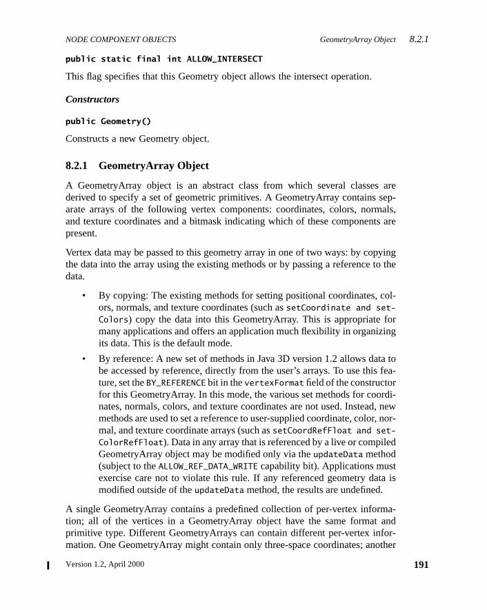
NODE COMPONENT OBJECTS GeometryArray Object8.2.1
areep-als,
s are
yingto the
ol-
orng
a tofea-
di-, new, nor-
d
a is
a-andr-ther
public static final int ALLOW_INTERSECT
This flag specifies that this Geometry object allows the intersect operation.
Constructors
public Geometry()
Constructs a new Geometry object.
8.2.1 GeometryArray Object
A GeometryArray object is an abstract class from which several classesderived to specify a set of geometric primitives. A GeometryArray contains sarate arrays of the following vertex components: coordinates, colors, normand texture coordinates and a bitmask indicating which of these componentpresent.
Vertex data may be passed to this geometry array in one of two ways: by copthe data into the array using the existing methods or by passing a referencedata.
• By copying: The existing methods for setting positional coordinates, cors, normals, and texture coordinates (such assetCoordinate and set-
Colors) copy the data into this GeometryArray. This is appropriate fmany applications and offers an application much flexibility in organiziits data. This is the default mode.
• By reference: A new set of methods in Java 3D version 1.2 allows datbe accessed by reference, directly from the user’s arrays. To use thisture, set theBY_REFERENCE bit in thevertexFormat field of the constructorfor this GeometryArray. In this mode, the various set methods for coornates, normals, colors, and texture coordinates are not used. Insteadmethods are used to set a reference to user-supplied coordinate, colormal, and texture coordinate arrays (such assetCoordRefFloat and set-
ColorRefFloat). Data in any array that is referenced by a live or compileGeometryArray object may be modified only via theupdateData method(subject to theALLOW_REF_DATA_WRITE capability bit). Applications mustexercise care not to violate this rule. If any referenced geometry datmodified outside of theupdateData method, the results are undefined.
A single GeometryArray contains a predefined collection of per-vertex informtion; all of the vertices in a GeometryArray object have the same formatprimitive type. Different GeometryArrays can contain different per-vertex infomation. One GeometryArray might contain only three-space coordinates; ano
191Version 1.2, April 2000
8.2.1 GeometryArray Object NODE COMPONENT OBJECTS
192
ates;
al-thegthned
rip-n
th-imi-s
of
of
of
of
might contain per-vertex coordinates, normals, colors, and texture coordinyet another might contain any subset of the previous example.
All colors used in the GeometryArray object must be in the range [0.0, 1.0]. Vues outside this range will cause undefined results. All normals used inGeometryArray object must be unit length vectors; that is, their geometric lenmust be 1.0. Normals that are not unit length vectors will cause undefiresults.
Note that the termcoordinate, as used in the method names and method desctions, actually refers to a set ofx, y, andz coordinates representing the positioof a single vertex. The termcoordinates(plural) is used to indicate sets ofx, y,andz coordinates for multiple vertices. This is somewhat at odds with the maematical definition of a coordinate but is used as a convenient shorthand. Slarly, the termtexture coordinateis used to indicate a set of texture coordinatefor a single vertex, while the termtexture coordinates(plural) is used to indicatesets of texture coordinates for multiple vertices.
Constants
The GeometryArray object defines the following flags:
public static final int ALLOW_COORDINATE_READpublic static final int ALLOW_COORDINATE_WRITE
These flags specify that the GeometryArray object allows reading or writingthe array of coordinates.
public static final int ALLOW_COLOR_READpublic static final int ALLOW_COLOR_WRITE
These flags specify that the GeometryArray object allows reading or writingthe array of colors.
public static final int ALLOW_NORMAL_READpublic static final int ALLOW_NORMAL_WRITE
These flags specify that the GeometryArray object allows reading or writingthe array of normals.
public static final int ALLOW_TEXCOORD_READpublic static final int ALLOW_TEXCOORD_WRITE
These flags specify that the GeometryArray object allows reading or writingthe array of texture coordinates.
The Java 3D API Specification
NODE COMPONENT OBJECTS GeometryArray Object8.2.1
ofthe
for-
m-writ-used
a for
a forrrayem-
andx
as aThe
ew in 1.2
ew in 1.2
ew in 1.2
ew in 1.2
ew in 1.2
public static final int ALLOW_COUNT_READpublic static final int ALLOW_COUNT_WRITE
These flags specify that the GeometryArray object allows reading or writingany count or initial index data (such as the vertex count) associated withGeometryArray.
public static final int ALLOW_FORMAT_READ
This flag specifies that the GeometryArray object allows reading the vertexmat associated with the GeometryArray.
public static final int ALLOW_REF_DATA_READpublic static final int ALLOW_REF_DATA_WRITE
These flags specify that this GeometryArray allows reading or writing the geoetry data reference information for this object. The second flag also enablesing the referenced data itself, via the GeometryUpdater interface. These areonly in by-reference geometry mode.
public static final int BY_REFERENCE
This flag specifies that the position, color, normal, and texture coordinate datthis GeometryArray are accessed by reference.
public static final int INTERLEAVED
This flag specifies that the position, color, normal, and texture coordinate datthis GeometryArray are accessed via a single interleaved, floating-point areference. All of the data values for each vertex are stored in consecutive mory locations. This is valid only in conjunction with theBY_REFERENCE flag.
Constructors
The GeometryArray object has the following constructors:
public GeometryArray(int vertexCount, int vertexFormat)
Constructs an empty GeometryArray object with the specified vertex formatnumber of vertices. ThevertexCount parameter specifies the number of verteelements in this array. ThevertexFormat parameter is a mask indicating whichvertex components are present in each vertex. The vertex format is specifiedset of flags that are bitwise ORed together to describe the per-vertex data.following vertex formats are supported:
N
N
N
N
N
193Version 1.2, April 2000
8.2.1 GeometryArray Object NODE COMPONENT OBJECTS
194
his
a.
orspre-
D
x-
n by
gle
rti-inate
New in 1.2
• COORDINATES: Specifies that this vertex array contains coordinates. Tbit must be set.
• NORMALS: Specifies that this vertex array contains normals.
• COLOR_3: Specifies that this vertex array contains colors without alphColors are specified as floating-point values in the range [0.0, 1.0].
• COLOR_4: Specifies that this vertex array contains colors with alpha. Colare specified as floating-point values in the range [0.0, 1.0]. This takescedence overCOLOR_3.
• TEXTURE_COORDINATE_2: Specifies that this vertex array contains 2texture coordinates (S and T).
• TEXTURE_COORDINATE_3: Specifies that this vertex array contains 3D teture coordinates (S, T, and R). This takes precedence overTEXTURE_
COORDINATE_2.
• BY_REFERENCE: Indicates that the data is passed by reference rather thacopying.
• INTERLEAVED: Indicates that the referenced data is interleaved in a sinarray.
The GeometryArray object is constructed with the following default values:
public GeometryArray(int vertexCount, int vertexFormat, int texCoordSetCount, int[] texCoordSetMap)
Constructs an empty GeometryArray object with the specified number of veces, vertex format, number of texture coordinate sets, and texture coordmapping array. Defaults are used for all other parameters.
Parameter Default Value
texCoordSetCount 1
texCoordSetMap { 0 }
validVertexCount vertexCount
initialVertexIndex 0
initialCoordIndex 0
initialColorIndex 0
initialNormalIndex 0
initialTexCoordIndex 0
all data array values 0.0
all data array references null
The Java 3D API Specification
NODE COMPONENT OBJECTS GeometryArray Object8.2.1
te
ateturetex-
rre-an
set
entsextureit inates:pinggen-ate
of
r as
The texCoordSetCount parameter specifies the number of texture coordinasets in this GeometryArray object. If thevertexFormat parameter does notinclude one ofTEXTURE_COORDINATE_2 or TEXTURE_COORDINATE_3, the texCo-
ordSetCount parameter is not used.
The texCoordSetMap parameter specifies an array that maps texture coordinsets to texture units. The array is indexed by texture unit number for each texunit in the associated Appearance object. The values in the array specify theture coordinate set within this GeometryArray object that maps to the cosponding texture unit. All elements within the array must be less thtexCoordSetCount. A negative value specifies that no texture coordinatemaps to the texture unit corresponding to the index.
If there are more texture units in any associated Appearance object than elemin the mapping array, the extra elements are assumed to be –1. The same tcoordinate set may be used for more than one texture unit. Each texture unevery associated Appearance must have a valid source of texture coordinEither a nonnegative texture coordinate set must be specified in the maparray, or texture coordinate generation must be enabled. Texture coordinateeration will take precedence for those texture units for which a texture coordinset is specified and texture coordinate generation is enabled. IfvertexFormat
does not include one ofTEXTURE_COORDINATE_2 or TEXTURE_COORDINATE_3, thetexCoordSetMap array is not used. The following example illustrates the usethetexCoordSetMap array.
Methods
GeometryArray methods provide access (get and set methods) to individualvertex component arrays in two different modes: as individual elements oarrays of multiple elements.
public int getVertexCount()
Retrieves the number of vertices in the GeometryArray.
Index Element Description
0 1 Use texture coordinate set 1 for texture unit 0
1 –1 Use no texture coordinate set for texture unit 1
2 0 Use texture coordinate set 0 for texture unit 2
3 1 Reuse texture coordinate set 1 for texture unit 3
195Version 1.2, April 2000
8.2.1 GeometryArray Object NODE COMPONENT OBJECTS
196
. Thisct torrayvia
ple,ally
unttions
hisd inini-etry
y.rdi-
New in 1.2
New in 1.2
New in 1.2
New in 1.2
New in 1.2
public int getVertexFormat()
Retrieves the vertex format of the GeometryArray.
public void updateData(GeometryUpdater updater)
This method updates geometry array data that is accessed by referencemethod calls the updateData method of the specified GeometryUpdater objesynchronize updates to vertex data that is referenced by this GeometryAobject. Applications that wish to modify such data must perform all updatesthis method.
This method may also be used to set multiple references atomically (for examto coordinate and color arrays) or to change multiple data values atomicthrough the geometry data copying methods.
public void setValidVertexCount(int validVertexCount)public int getValidVertexCount()
Sets or retrieves the valid vertex count for this GeometryArray object. This cospecifies the number of vertices actually used in rendering or other operasuch as picking and collision. This attribute is initialized tovertexCount.
public void setInitialVertexIndex(int initialVertexIndex)public int getInitialVertexIndex()
Sets or retrieves the initial vertex index for this GeometryArray object. Tindex specifies the first vertex within this geometry array that is actually userendering or other operations such as picking and collision. This attribute istialized to 0. This attribute is used only when the data mode for this geomarray object is notBY_REFERENCE.
public void setCoordinate(int index, float coordinate[])public void getCoordinate(int index, float coordinate[])public void setCoordinate(int index, double coordinate[])public void getCoordinate(int index, double coordinate[])
Sets or retrieves the coordinate associated with the vertex at the specifiedindex
of this object. Theindex parameter is the vertex index in this geometry arraThecoordinate parameter is an array of three values containing the new coonate.
public void setCoordinate(int index, Point3f coordinate)public void getCoordinate(int index, Point3f coordinate)public void setCoordinate(int index, Point3d coordinate)public void getCoordinate(int index, Point3d coordinate)
The Java 3D API Specification
NODE COMPONENT OBJECTS GeometryArray Object8.2.1
spec-ry
-
spec-ryi-s
t thedexx
Sets or retrieves the coordinate associated with the vertex at the specifiedindex.Theindex parameter is the vertex index in this geometry array. Thecoordinate
parameter is a vector containing the new coordinate.
public void setCoordinates(int index, float coordinates[])public void getCoordinates(int index, float coordinates[])public void setCoordinates(int index, double coordinates[])public void getCoordinates(int index, double coordinates[])
Sets or retrieves the coordinates associated with the vertices starting at theified index. The index parameter is the starting vertex index in this geometarray. Thecoordinates parameter is an array of 3n values containingn newcoordinates. The length of thecoordinates array determines the number of vertices copied.
public void setCoordinates(int index, Point3f coordinates[])public void getCoordinates(int index, Point3f coordinates[])public void setCoordinates(int index, Point3d coordinates[])public void getCoordinates(int index, Point3d coordinates[])
Sets or retrieves the coordinates associated with the vertices starting at theified index. The index parameter is the starting vertex index in this geometarray. Thecoordinates parameter is an array of points containing new coordnates. The length of thecoordinates array determines the number of verticecopied.
public void setCoordinates(int index, Point3d coordinates[], int start, int length)public void setCoordinates(int index, Point3f coordinates[], int start, int length)public void setCoordinates(int index, float coordinates[], int start, int length)public void setCoordinates(int index, double coordinates[], int start, int length)
These methods set the coordinates associated with the vertices starting aspecified index for this object, using coordinate data starting from vertex instart for length vertices. Theindex parameter is the starting destination verteindex in this geometry array.
197Version 1.2, April 2000
8.2.1 GeometryArray Object NODE COMPONENT OBJECTS
198
The
The
cifieday.
cifieday.he
public void setColor(int index, float color[])public void getColor(int index, float color[])public void setColor(int index, byte color[])public void getColor(int index, byte color[])
Sets or retrieves the color associated with the vertex at the specified index.index parameter is the vertex index in this geometry array. Thecolor parameteris an array of three or four values containing the new color.
public void setColor(int index, Color3f color)public void getColor(int index, Color3f color)public void setColor(int index, Color4f color)public void getColor(int index, Color4f color)public void setColor(int index, Color3b color)public void getColor(int index, Color3b color)public void setColor(int index, Color4b color)public void getColor(int index, Color4b color)
Sets or retrieves the color associated with the vertex at the specified index.index parameter is the vertex index in this geometry array. Thecolor parameteris a vector containing the new color.
public void setColors(int index, float colors[])public void getColors(int index, float colors[])public void setColors(int index, byte colors[])public void getColors(int index, byte colors[])
Sets or retrieves the colors associated with the vertices starting at the speindex. Theindex parameter is the starting vertex index in this geometry arrThe colors parameter is an array of 3n or 4n values containingn new colors.The length of thecolors array determines the number of vertices copied.
public void setColors(int index, Color3f colors[])public void getColors(int index, Color3f colors[])public void setColors(int index, Color4f colors[])public void getColors(int index, Color4f colors[])public void setColors(int index, Color3b colors[])public void getColors(int index, Color3b colors[])public void setColors(int index, Color4b colors[])public void getColors(int index, Color4b colors[])
Sets or retrieves the colors associated with the vertices starting at the speindex. Theindex parameter is the starting vertex index in this geometry arrThe colors parameter is an array of vectors containing the new colors. Tlength of thecolors array determines the number of vertices copied.
The Java 3D API Specification
NODE COMPONENT OBJECTS GeometryArray Object8.2.1
cified
m-
cified
m-.
. The
. The
cifieday.
public void setColors(int index, float colors[], int start, int length)public void setColors(int index, byte colors[], int start, int length)
These methods set the colors associated with the vertices starting at the speindex for this object, using data incolors starting at indexstart for length
colors. Theindex parameter is the starting destination vertex index in this geoetry array. Thecolors parameter is an array of 3n or 4n values containingn newcolors.
public void setColors(int index, Color3f colors[], int start, int length)public void setColors(int index, Color4f colors[], int start, int length)public void setColors(int index, Color3b colors[], int start, int length)public void setColors(int index, Color4b colors[], int start, int length)
These methods set the colors associated with the vertices starting at the speindex for this object, using data incolors starting at indexstart for length
colors. Theindex parameter is the starting destination vertex index in this geoetry array. Thecolors parameter is an array of vectors containing new colors
public void setNormal(int index, float normal[])public void getNormal(int index, float normal[])
Sets or retrieves the normal associated with the vertex at the specified indexindex parameter is the vertex index in this geometry array. Thenormal parame-ter is the new normal.
public void setNormal(int index, Vector3f normal)public void getNormal(int index, Vector3f normal)
Sets or retrieves the normal associated with the vertex at the specified indexindex parameter is the vertex index in this geometry array. Thenormal parame-ter is a vector containing the new normal.
public void setNormals(int index, float normals[])public void getNormals(int index, float normals[])
Sets or retrieves the normals associated with the vertices starting at the speindex. Theindex parameter is the starting vertex index in this geometry arrThe normals parameter is an array of 3n values containingn new normals. Thelength of thenormals array determines the number of vertices copied.
199Version 1.2, April 2000
8.2.1 GeometryArray Object NODE COMPONENT OBJECTS
200
cifieday.he
speci-
n
etry-
y of
om-
ertex
New in 1.2
New in 1.2
New in 1.2
New in 1.2
New in 1.2
New in 1.2
New in 1.2
New in 1.2
New in 1.2
public void setNormals(int index, Vector3f normals[])public void getNormals(int index, Vector3f normals[])
Sets or retrieves the normals associated with the vertices starting at the speindex. Theindex parameter is the starting vertex index in this geometry arrThe normals parameter is an array of vectors containing new normals. Tlength of thenormals array determines the number of vertices copied.
public void setNormals(int index, float normals[], int start, int length)public void setNormals(int index, Vector3f normals[], int start, int length)
These methods set the normals associated with the vertices starting at thefied index for this object, using data innormals starting at indexstart and end-ing at index start+length. The index parameter is the starting destinatiovertex index in this geometry array.
public int getTexCoordSetCount()
This method retrieves the number of texture coordinate sets in this GeomArray object.
public int getTexCoordSetMapLength()
This method retrieves the length of the texture coordinate set mapping arrathis GeometryArray object.
public void getTexCoordSetMap(int[] texCoordSetMap)
This method retrieves the texture coordinate set mapping array from this GeetryArray object.
public void setTextureCoordinate(int texCoordSet, int index, float[] texCoord)public void setTextureCoordinate(int texCoordSet, int index, TexCoord2f texCoord)public void setTextureCoordinate(int texCoordSet, int index, TexCoord3f texCoord)public void getTextureCoordinate(int texCoordSet, int index, float[] texCoord)public void getTextureCoordinate(int texCoordSet, int index, TexCoord2f texCoord)public void getTextureCoordinate(int texCoordSet, int index, TexCoord3f texCoord)
These methods set and retrieve the texture coordinate associated with the vat the specified index in the specified texture coordinate set for this object.
The Java 3D API Specification
NODE COMPONENT OBJECTS GeometryArray Object8.2.1
verti-this
. Forer of
verti-this
dex
ew in 1.2
ew in 1.2
ew in 1.2
ew in 1.2
ew in 1.2
ew in 1.2
ew in 1.2
ew in 1.2
ew in 1.2
public void setTextureCoordinates(int texCoordSet, int index, float[] texCoords)public void setTextureCoordinates(int texCoordSet, int index, TexCoord2f[] texCoords)public void setTextureCoordinates(int texCoordSet, int index, TexCoord3f[] texCoords)public void getTextureCoordinates(int texCoordSet, int index, float[] texCoords)public void getTextureCoordinates(int texCoordSet, int index, TexCoord2f[] texCoords)public void getTextureCoordinates(int texCoordSet, int index, TexCoord3f[] texCoords)
These methods set and retrieve the texture coordinates associated with theces starting at the specified index in the specified texture coordinate set forobject. The set methods copy the entire source array to this geometry arraythe get methods, the length of the destination array determines the numbtexture coordinates copied.
public void setTextureCoordinates(int texCoordSet, int index, float[] texCoords, int start, int length)public void setTextureCoordinates(int texCoordSet, int index, TexCoord2f[] texCoords, int start, int length)public void setTextureCoordinates(int texCoordSet, int index, TexCoord3f[] texCoords, int start, int length)
These methods set and retrieve the texture coordinates associated with theces starting at the specified index in the specified texture coordinate set forobject using data in texCoords starting at index start and ending at instart+length.
public void setTextureCoordinate(int index, float texCoord[])public void getTextureCoordinate(int index, float texCoord[])public void setTextureCoordinate(int index, Point2f texCoord)public void getTextureCoordinate(int index, Point2f texCoord)public void setTextureCoordinate(int index, Point3f texCoord)public void getTextureCoordinate(int index, Point3f texCoord)public void setTextureCoordinates(int index, float texCoords[])public void getTextureCoordinates(int index, float texCoords[])public void setTextureCoordinates(int index, Point2f texCoords[])public void getTextureCoordinates(int index, Point2f texCoords[])public void setTextureCoordinates(int index, Point3f texCoords[])public void getTextureCoordinates(int index, Point3f texCoords[])public void setTextureCoordinates(int index, float texCoords[], int start, int length)public void setTextureCoordinates(int index, Point2f texCoords[], int start, int length)
N
N
N
N
N
N
N
N
N
201Version 1.2, April 2000
8.2.1 GeometryArray Object NODE COMPONENT OBJECTS
202
hisd byuch
ed
extryand
he
histhish asly
oor-ureetryand
he
New in 1.2
New in 1.2
New in 1.2
New in 1.2
New in 1.2
New in 1.2
New in 1.2
New in 1.2
New in 1.2
New in 1.2
New in 1.2
public void setTextureCoordinates(int index, Point3f texCoords[], int start, int length)
These methods are deprecated in Java 3D version 1.2.
public void setInitialCoordIndex(int initialCoordIndex)public int getInitialCoordIndex()
Sets or retrieves the initial coordinate index for this GeometryArray object. Tindex specifies the first coordinate within the array of coordinates referencethis geometry array that is actually used in rendering or in other operations sas picking and collision. This attribute is initialized to 0. This attribute is usonly when the data mode for this geometry array object isBY_REFERENCE.
public void setInitialColorIndex(int initialColorIndex)public int getInitialColorIndex()
Sets or retrieves the initial color index for this GeometryArray object. This indspecifies the first color within the array of colors referenced by this geomearray that is actually used in rendering or other operations such as pickingcollision. This attribute is initialized to 0. This attribute is used only when tdata mode for this geometry array object isBY_REFERENCE.
public void setInitialNormalIndex(int initialNormalIndex)public int getInitialNormalIndex()
Sets or retrieves the initial normal index for this GeometryArray object. Tindex specifies the first normal within the array of normals referenced bygeometry array that is actually used in rendering or other operations sucpicking and collision. This attribute is initialized to 0. This attribute is used onwhen the data mode for this geometry array object isBY_REFERENCE.
public void setInitialTexCoordIndex(int texCoordSet, int initialTexCoordIndex)public int getInitialTexCoordIndex(int texCoordSet)
Sets or retrieves the initial texture coordinate index for the specified texture cdinate set for this GeometryArray object. This index specifies the first textcoordinate within the array of texture coordinates referenced by this geomarray that is actually used in rendering or other operations such as pickingcollision. This attribute is initialized to 0. This attribute is used only when tdata mode for this geometry array object isBY_REFERENCE.
public void setCoordRefFloat(float[] coords)public float[] getCoordRefFloat()public void setCoordRefDouble(double[] coords)
The Java 3D API Specification
NODE COMPONENT OBJECTS GeometryArray Object8.2.1
array
sulttherph
array
-nuller-any
con-
ofwn.For-
etry
ew in 1.2
ew in 1.2
ew in 1.2
ew in 1.2
ew in 1.2
ew in 1.2
ew in 1.2
ew in 1.2
ew in 1.2
ew in 1.2
ew in 1.2
ew in 1.2
ew in 1.2
public double[] getCoordRefDouble()
Sets or retrieves the coordinate array reference to the specified array. Thecontainsx, y, andz values for each vertex (for a total of 3*n values, wheren isthe number of vertices). Only one ofcoordRefFloat, coordRefDouble,coordRef3f, or coordRef3d may be non-null (or they may all be null). Anattempt to set more than one of these attributes to a non-null reference will rein an exception being thrown. If all coordinate array references are null,entire geometry array object is treated as if it were null—any Shape3D or Monode that uses this geometry array will not be drawn.
public void setCoordRef3f(Point3f[] coords)public Point3f[] getCoordRef3f()public void setCoordRef3d(Point3d[] coords)public Point3d[] getCoordRef3d()
Sets or retrieves the coordinate array reference to the specified array. Thecontains a Point3f or Point3d object for each vertex. Only one ofcoordRef-
Float, coordRefDouble, coordRef3f, or coordRef3d may be non-null (or theymay all be null). An attempt to set more than one of these attributes to a nonreference will result in an exception being thrown. If all coordinate array refences are null, the entire geometry array object is treated as if it were null—Shape3D or Morph node that uses this geometry array will not be drawn.
public void setColorRefFloat(float[] colors)public float[] getColorRefFloat()public void setColorRefByte(byte[] colors)public byte[] getColorRefByte()
Sets or retrieves the color array reference to the specified array. The arraytainsred, green, blue, and, optionally,alphavalues for each vertex (for a total of3*n or 4*n values, wheren is the number of vertices). Only one ofcolorRef-Float, colorRefByte, colorRef3f, colorRef4f, colorRef3b, or colorRef4bmay be non-null (or they may all be null). An attempt to set more than onethese attributes to a non-null reference will result in an exception being throIf all color array references are null and colors are enabled (that is, the vertexmat includes eitherCOLOR_3 or COLOR_4), the entire geometry array object istreated as if it were null—any Shape3D or Morph node that uses this geomarray will not be drawn.
public void setColorRef3f(Color3f[] colors)public Color3f[] getColorRef3f()public void setColorRef4f(Color4f[] colors)public Color4f[] getColorRef4f()
N
N
N
N
N
N
N
N
N
N
N
N
N
203Version 1.2, April 2000
8.2.1 GeometryArray Object NODE COMPONENT OBJECTS
204
con-ne
retiont is,
this
array
retionbled
etry
con-
retionbled
etry
New in 1.2New in 1.2
New in 1.2
New in 1.2
New in 1.2
New in 1.2
New in 1.2
New in 1.2
New in 1.2
New in 1.2
public void setColorRef3b(Color3b[] colors)public Color3b[] getColorRef3b()public void setColorRef4b(Color4b[] colors)public Color4b[] getColorRef4b()
Sets or retrieves the color array reference to the specified array. The arraytains a Color 3f, Color4f, Color3b, or Color4b object for each vertex. Only oof colorRefFloat, colorRefByte, colorRef3f, colorRef4f, colorRef3b, orcolorRef4b may be non-null (or they may all be null). An attempt to set mothan one of these attributes to a non-null reference will result in an excepbeing thrown. If all color array references are null and colors are enabled (thathe vertexFormat includes eitherCOLOR_3 or COLOR_4), the entire geometry arrayobject is treated as if it were null—any Shape3D or Morph node that usesgeometry array will not be drawn.
public void setNormalRefFloat(float[] normals)public float[] getNormalRefFloat()
Sets or retrieves the float normal array reference to the specified array. Thecontains floating-pointnx, ny, andnz values for each vertex (for a total of 3*nvalues, wheren is the number of vertices). Only one ofnormalRefFloat ornormalRef3f may be non-null (or they may all be null). An attempt to set mothan one of these attributes to a non-null reference will result in an excepbeing thrown. If all normal array references are null and normals are ena(that is, the vertexFormat includesNORMAL), the entire geometry array object istreated as if it were null—any Shape3D or Morph node that uses this geomarray will not be drawn.
public void setNormalRef3f(Vector3f[] normals)public Vector3f[] getNormalRef3f()
Sets or retrieves the normal array reference to the specified array. The arraytains a Vector3f object for each vertex. Only one ofnormalRefFloat ornormalRef3f may be non-null (or they may all be null). An attempt to set mothan one of these attributes to a non-null reference will result in an excepbeing thrown. If all normal array references are null and normals are ena(that is, the vertexFormat includesNORMAL), the entire geometry array object istreated as if it were null—any Shape3D or Morph node that uses this geomarray will not be drawn.
public void setTexCoordRefFloat(int texCoordSet, float[] texCoords)public float[] getTexCoordRefFloat(int texCoordSet)
The Java 3D API Specification
NODE COMPONENT OBJECTS GeometryArray Object8.2.1
tex-
setcep-rdi-
etry
te sett for
ofwn.(that
—.
. Theorderoseertexbled,
rr ver-ose
ew in 1.2
ew in 1.2
ew in 1.2
ew in 1.2
ew in 1.2
ew in 1.2
Sets or retrieves the float texture coordinate array reference for the specifiedture coordinate set to the specified array. The array contains floating-points, t,and, optionally,r values for each vertex (for a total of 2*n or 3*n values, wheren is the number of vertices). Only one oftexCoordRefFloat, texCoordRef2f,or texCoordRef3f may be non-null (or they may all be null). An attempt tomore than one of these attributes to a non-null reference will result in an extion being thrown. If all texCoord array references are null and texture coonates are enabled (that is, the vertexFormat includes eitherTEXTURE_
COORDINATE_2 or TEXTURE_COORDINATE_3), the entire geometry array object istreated as if it were null—any Shape3D or Morph node that uses this geomarray will not be drawn.
public void setTexCoordRef2f(int texCoordSet, TexCoord2f[] texCoords)public TexCoord2f[] getTexCoordRef2f(int texCoordSet)public void setTexCoordRef3f(int texCoordSet, TexCoord3f[] texCoords)public TexCoord3f[] getTexCoordRef3f(int texCoordSet)
Sets the texture coordinate array reference for the specified texture coordinato the specified array. The array contains a TexCoord2f or TexCoord3f objeceach vertex. Only one oftexCoordRefFloat, texCoordRef2f, or texCoordRef3fmay be non-null (or they may all be null). An attempt to set more than onethese attributes to a non-null reference will result in an exception being throIf all texCoord array references are null and texture coordinates are enabledis, the vertexFormat includes eitherTEXTURE_COORDINATE_2 or TEXTURE_
COORDINATE_3), the entire geometry array object is treated as if it were nullany Shape3D or Morph node that uses this geometry array will not be drawn
public void setInterleavedVertices(float[] vertexData)public float[] getInterleavedVertices()
Sets or retrieves the interleaved vertices array reference to the specified arrayvertex components must be stored in a predetermined order in the array. Theis texture coordinates, colors, normals, and positional coordinates. Only thcomponents that are enabled appear in the vertex. The number of words per vdepends on which vertex components are enabled. Texture coordinates, if enause two words per vertex forTEXTURE_COORDINATE_2 or three words per vertex forTEXTURE_COORDINATE_3. Colors, if enabled, use three words per vertex forCOLOR_
3 or four words per vertex forCOLOR_4. Normals, if enabled, use three words pevertex. Positional coordinates, which are always enabled, use three words petex. For example, the format of interleaved data for a GeometryArray object whvertexFormat includesCOORDINATES, COLOR_3, andNORMALS would bered, green,
N
N
N
N
N
N
205Version 1.2, April 2000
8.2.2 GeometryUpdater Interface NODE COMPONENT OBJECTS
206
rythe
t isseechclass
hod iseh to
n it.
eth-
nd
New in 1.2
New in 1.2
blue, Nx, Ny, Nz, x, y, z. All components of a vertex are stored in adjacent memolocations. The first component of vertex 0 is stored beginning at index 0 inarray. The first component of vertex 1 is stored beginning at indexwords_per_ver-texin the array. The total number of words needed to storen vertices iswords_per_vertex*n.
8.2.2 GeometryUpdater Interface
The GeometryUpdater interface is used in updating geometry data thaaccessed by reference from a live or compiled GeometryArray object (Section 8.2.1, “GeometryArray Object”). Applications that wish to modify sudata must define a class that implements this interface. An instance of thatis then passed to theupdateData method of the GeometryArray object to bemodified.
Methods
public void updateData(Geometry geometry)
This method updates geometry data that is accessed by reference. This metcalled by theupdateData method of a GeometryArray object to effect safupdates to vertex data that is referenced by that object. Applications that wismodify such data must implement this method and perform all updates withi
Note: Applications should not call this method directly.
8.2.3 PointArray Object
The PointArray object extends GeometryArray and provides no additional mods. Objects of this class draw the array of vertices as individual points.
Constructors
public PointArray(int vertexCount, int vertexFormat)
Constructs an empty PointArray object with the specified vertex format anumber of vertices.
public PointArray(int vertexCount, int vertexFormat, int texCoordSetCount, int[] texCoordSetMap)
The Java 3D API Specification
NODE COMPONENT OBJECTS TriangleArray Object8.2.5
es,ping
th-nts.
m-
ver-ping
nalles.
and
es,ping
ew in 1.2
ew in 1.2
Constructs an empty PointArray object with the specified number of verticvertex format, number of texture coordinate sets, and texture coordinate maparray.
8.2.4 LineArray Object
The LineArray object extends GeometryArray and provides no additional meods. Objects of this class draw the array of vertices as individual line segmeEach pair of vertices defines a line segment to be drawn.
Constructors
public LineArray(int vertexCount, int vertexFormat)
Constructs an empty LineArray object with the specified vertex format and nuber of vertices.
public LineArray(int vertexCount, int vertexFormat, int texCoordSetCount, int[] texCoordSetMap)
Constructs an empty LineArray object with the specified number of vertices,tex format, number of texture coordinate sets, and texture coordinate maparray.
8.2.5 TriangleArray Object
The TriangleArray object extends GeometryArray and provides no additiomethods. Objects of this class draw the array of vertices as individual triangEach group of three vertices defines a triangle to be drawn.
Constructors
public TriangleArray(int vertexCount, int vertexFormat)
Constructs an empty TriangleArray object with the specified vertex formatnumber of vertices.
public TriangleArray(int vertexCount, int vertexFormat, int texCoordSetCount, int[] texCoordSetMap)
Constructs an empty TriangleArray object with the specified number of verticvertex format, number of texture coordinate sets, and texture coordinate maparray.
N
N
207Version 1.2, April 2000
8.2.6 QuadArray Object NODE COMPONENT OBJECTS
208
eth-rals.eralren-the
and
ces,ping
nethe
e-ifies
r of
hes theified
New in 1.2
8.2.6 QuadArray Object
The QuadArray object extends GeometryArray and provides no additional mods. Objects of this class draw the array of vertices as individual quadrilateEach group of four vertices defines a quadrilateral to be drawn. A quadrilatmust be planar and convex or results are undefined. A quadrilateral may bedered as a pair of triangles with either diagonal line arbitrarily chosen to splitquad.
Constructors
public QuadArray(int vertexCount, int vertexFormat)
Constructs an empty QuadArray object with the specified vertex formatnumber of vertices.
public QuadArray(int vertexCount, int vertexFormat, int texCoordSetCount, int[] texCoordSetMap)
Constructs an empty QuadArray object with the specified number of vertivertex format, number of texture coordinate sets, and texture coordinate maparray.
8.2.7 GeometryStripArray Object
GeometryStripArray is an abstract class from which all strip primitives (listrip, triangle strip, and triangle fan) are derived. In addition to specifyingarray of vertex elements, which is inherited from GeometryArray, the GeomtryStripArray class specifies an array of per-strip vertex counts that specwhere the separate strips appear in the vertex array.
Constructors
The GeometryStripArray object has the following constructors:
public GeometryStripArray(int vertexCount, int vertexFormat, int stripVertexCounts[])
Constructs an empty GeometryStripArray object with the specified numbevertices, vertex format, and an array of vertex counts per strip. ThevertexCount
parameter specifies the number of vertex elements in this array.
The stripVertexCounts parameter is an array that specifies the count of tnumber of vertices for each separate strip. The length of this array specifienumber of separate strips. The sum of the vertex counts for all strips, as spec
The Java 3D API Specification
NODE COMPONENT OBJECTS LineStripArray Object8.2.8
s
r ofnate
nald linetripswithrevi-
es,
es,ping
ew in 1.2
ew in 1.2
by the stripVertexCounts array, must equal the total count of all vertices aspecified by thevertexCount parameter.
public GeometryStripArray(int vertexCount, int vertexFormat, int texCoordSetCount, int[] texCoordSetMap, int[] stripVertexCounts)
Constructs an empty GeometryStripArray object with the specified numbevertices, vertex format, number of texture coordinate sets, texture coordimapping array, and array of per-strip vertex counts.
Methods
The GeometryStripArray object has the following methods:
public int getNumStrips()
This method returns the number of strips in the GeometryStripArray.
public void getStripVertexCounts(int stripVertexCounts[])
This method gets an array containing a list of vertex counts for each strip.
8.2.8 LineStripArray Object
The LineStripArray extends GeometryStripArray and provides no additiomethods. Objects of this class draw an array of vertices as a set of connectestrips. An array of per-strip vertex counts specifies where the separate sappear in the vertex array. For every strip in the set, each vertex, beginningthe second vertex in the array, defines a line segment to be drawn from the pous vertex to the current vertex.
Constructors
public LineStripArray(int vertexCount, int vertexFormat, int stripVertexCounts[])
Constructs an empty LineStripArray object with the specified number of verticvertex format, and array of vertex counts per strip.
public LineStripArray(int vertexCount, int vertexFormat, int texCoordSetCount, int[] texCoordSetMap, int[] stripVertexCounts)
Constructs an empty LineStripArray object with the specified number of verticvertex format, number of texture coordinate sets, texture coordinate maparray, and array of per-strip vertex counts.
N
N
209Version 1.2, April 2000
8.2.9 TriangleStripArray Object NODE COMPONENT OBJECTS
210
nald tri-rateningrent
er-
er-ap-
nald tri-stripsningrentcol-
rti-
New in 1.2
8.2.9 TriangleStripArray Object
The TriangleStripArray extends GeometryStripArray and provides no additiomethods. Objects of this class draw an array of vertices as a set of connecteangle strips. An array of per-strip vertex counts specifies where the sepastrips appear in the vertex array. For every strip in the set, each vertex, beginwith the third vertex in the array, defines a triangle to be drawn using the curvertex and the two previous vertices.
Constructors
public TriangleStripArray(int vertexCount, int vertexFormat, int stripVertexCounts[])
Constructs an empty TriangleStripArray object with the specified number of vtices, vertex format, and array of vertex counts per strip.
public TriangleStripArray(int vertexCount, int vertexFormat, int texCoordSetCount, int[] texCoordSetMap, int[] stripVertexCounts)
Constructs an empty TriangleStripArray object with the specified number of vtices, vertex format, number of texture coordinate sets, texture coordinate mping array, and array of per-strip vertex counts.
8.2.10 TriangleFanArray Object
The TriangleFanArray extends GeometryStripArray and provides no additiomethods. Objects of this class draw an array of vertices as a set of connecteangle fans. An array of per-strip vertex counts specifies where the separate(fans) appear in the vertex array. For every strip in the set, each vertex, beginwith the third vertex in the array, defines a triangle to be drawn using the curvertex, the previous vertex, and the first vertex. This can be thought of as alection of convex polygons.
Constructors
public TriangleFanArray(int vertexCount, int vertexFormat, int stripVertexCounts[])
Constructs an empty TriangleFanArray object with the specified number of veces, vertex format, and array of vertex counts per strip.
The Java 3D API Specification
NODE COMPONENT OBJECTS IndexedGeometryArray Object8.2.11
rti-ping
etry-to
tes—rre-ture
or
or
or
or
ew in 1.2
public TriangleFanArray(int vertexCount, int vertexFormat, int texCoordSetCount, int[] texCoordSetMap, int[] stripVertexCounts)Constructs an empty TriangleFanArray object with the specified number of veces, vertex format, number of texture coordinate sets, texture coordinate maparray, and array of per-strip vertex counts.
8.2.11 IndexedGeometryArray Object
An IndexedGeometryArray object is an abstract class that extends GeomArray to allow vertex data to be accessed via a level of indirection. In additionthe separate arrays of coordinates, colors, normals, and texture coordinainherited from GeometryArray—an IndexedGeometryArray object adds cosponding arrays of coordinate indices, color indices, normal indices, and texcoordinate indices.
Constants
The IndexedGeometryArray object defines the following flags:
public static final int ALLOW_COORDINATE_INDEX_READpublic static final int ALLOW_COORDINATE_INDEX_WRITE
These flags specify that the IndexedGeometryArray object allows readingwriting of the array of coordinate indices.
public static final int ALLOW_COLOR_INDEX_READpublic static final int ALLOW_COLOR_INDEX_WRITE
These flags specify that the IndexedGeometryArray object allows readingwriting of the array of color indices.
public static final int ALLOW_NORMAL_INDEX_READpublic static final int ALLOW_NORMAL_INDEX_WRITE
These flags specify that the IndexedGeometryArray object allows readingwriting of the array of normal indices.
public static final int ALLOW_TEXCOORD_INDEX_READpublic static final int ALLOW_TEXCOORD_INDEX_WRITE
These flags specify that the IndexedGeometryArray object allows readingwriting of the array of texture coordinate indices.
N
211Version 1.2, April 2000
8.2.11 IndexedGeometryArray Object NODE COMPONENT OBJECTS
212
ame
r ofthe
e all
r ofnatedexd to
theele-
cified
at the
dex.
New in 1.2
Constructors
The IndexedGeometryArray object has two constructors that accept the sparameters as GeometryArray.
public IndexedGeometryArray(int vertexCount, int vertexFormat, int indexCount)
Constructs an empty IndexedGeometryArray object with the specified numbevertices, vertex format, and number of indices. The index values in each offour index arrays (coordinates, colors, normals, and texture coordinates) arinitialized to 0.
public IndexedGeometryArray(int vertexCount, int vertexFormat,int texCoordSetCount, int[] texCoordSetMap, int indexCount)
Constructs an empty IndexedGeometryArray object with the specified numbevertices, vertex format, number of texture coordinate sets, texture coordimapping array, and number of indices. The index values in each of the four inarrays (coordinates, colors, normals, and texture coordinates) are all initializezero.
Methods
IndexedGeometryArray methods provide access (get and set methods) to theindividual vertex component index arrays that are used when renderinggeometry. This access is allowed in two different modes: as individual indexments or as arrays of multiple index elements.
public void setCoordinateIndex(int index, int coordinateIndex)public int getCoordinateIndex(int index)
Sets or retrieves the coordinate index associated with the vertex at the speindex.
public void setCoordinateIndices(int index, int coordinateIndices[])public void getCoordinateIndices(int index, int coordinateIndices[])
Sets or retrieves the coordinate indices associated with the vertices startingspecified index.
public void setColorIndex(int index, int colorIndex)public int getColorIndex(int index)
Sets or retrieves the color index associated with the vertex at the specified in
The Java 3D API Specification
NODE COMPONENT OBJECTS IndexedGeometryArray Object8.2.11
spec-
ified
t the
th theject.
th thet for
ew in 1.2
ew in 1.2
ew in 1.2
ew in 1.2
public void setColorIndices(int index, int colorIndices[])public void getColorIndices(int index, int colorIndices[])
Sets or retrieves the color indices associated with the vertices starting at theified index.
public void setNormalIndex(int index, int normalIndex)public int getNormalIndex(int index)
Sets or retrieves the normal index associated with the vertex at the specindex.
public void setnormalIndices(int index, int normalIndices[])public void getNormalIndices(int index, int normalIndices[])
Sets or retrieves the normal indices associated with the vertices starting aspecified index.
public void setTextureCoordinateIndex(int texCoordSet, int index, int texCoordIndex)public int getTextureCoordinateIndex(int texCoordSet, int index)
These methods set and retrieve the texture coordinate index associated wivertex at the specified index in the specified texture coordinate set for this ob
public void setTextureCoordinateIndices(int texCoordSet, int index, int[] texCoordIndices)public void getTextureCoordinateIndices(int texCoordSet, int index, int[] texCoordIndices)
These methods set and retrieve the texture coordinate indices associated wivertices starting at the specified index in the specified texture coordinate sethis object.
public void setTextureCoordinateIndex(int index, int texCoordIndex)public int getTextureCoordinateIndex(int index)public void setTextureCoordinateIndices(int index, int texCoordIndices[])public void getTextureCoordinateIndices(int index, int texCoordIndices[])
These methods are deprecated in Java 3D version 1.2.
public int getIndexCount()
Retrieves the number of indices for this IndexedGeometryArray.
N
N
N
N
213Version 1.2, April 2000
8.2.12 IndexedPointArray Object NODE COMPONENT OBJECTS
214
s nodual
ver-rip-.
ver-ap-
nodual
ver-
(seetex
New in 1.2
New in 1.2
8.2.12 IndexedPointArray Object
The IndexedPointArray object extends IndexedGeometryArray and provideadditional methods. Objects of this class draw the array of vertices as indivipoints.
Constructors
The IndexedPointArray object has the following constructors:
public IndexedPointArray(int vertexCount, int vertexFormat, int indexCount)
Constructs an empty IndexedPointArray object with the specified number oftices, vertex format (see Section 8.2.1, “GeometryArray Object,” for a desction of the supported vertex formats), and the number of indices in this array
public IndexedPointArray(int vertexCount, int vertexFormat,int texCoordSetCount, int[] texCoordSetMap, int indexCount)
Constructs an empty IndexedPointArray object with the specified number oftices, vertex format, number of texture coordinate sets, texture coordinate mping array, and number of indices.
8.2.13 IndexedLineArray Object
The IndexedLineArray object extends IndexedGeometryArray and providesadditional methods. Objects of this class draw the array of vertices as indiviline segments. Each pair of vertices defines a line segment to be drawn.
Constructors
The IndexedLineArray object has the following constructors:
public IndexedLineArray(int vertexCount, int vertexFormat, int indexCount)
Constructs an empty IndexedLineArray object with the specified number oftices, vertex format, and the number of indices in this array. ThevertexFormat
is a mask indicating which components are present in each vertexSection 8.2.1, “GeometryArray Object,” for a description of the supported verformats).
public IndexedLineArray(int vertexCount, int vertexFormat,int texCoordSetCount, int[] texCoordSetMap, int indexCount)
The Java 3D API Specification
NODE COMPONENT OBJECTS IndexedQuadArray Object8.2.15
ver-ap-
idesivid-
r of
(seetex
r ofnate
s nodualn. Ateralsen
ew in 1.2
Constructs an empty IndexedLineArray object with the specified number oftices, vertex format, number of texture coordinate sets, texture coordinate mping array, and number of indices.
8.2.14 IndexedTriangleArray Object
The IndexedTriangleArray object extends IndexedGeometryArray and provno additional methods. Objects of this class draw the array of vertices as indual triangles. Each group of three vertices defines a triangle to be drawn.
Constructors
The IndexedTriangleArray object has the following constructors:
public IndexedTriangleArray(int vertexCount, int vertexFormat, int indexCount)
Constructs an empty IndexedTriangleArray object with the specified numbevertices, vertex format, and the number of indices in this array. ThevertexFor-
mat is a mask indicating which components are present in each vertexSection 8.2.1, “GeometryArray Object,” for a description of the supported verformats).
public IndexedTriangleArray(int vertexCount, int vertexFormat,int texCoordSetCount, int[] texCoordSetMap, int indexCount)
Constructs an empty IndexedTriangleArray object with the specified numbevertices, vertex format, number of texture coordinate sets, texture coordimapping array, and number of indices.
8.2.15 IndexedQuadArray Object
The IndexedQuadArray object extends IndexedGeometryArray and provideadditional methods. Objects of this class draw the array of vertices as indiviquadrilaterals. Each group of four vertices defines a quadrilateral to be drawquadrilateral must be planar and convex or results are undefined. A quadrilamay be rendered as a pair of triangles with either diagonal line arbitrarily choto split the quad.
Constructors
The IndexedQuadArray object has the following constructors:
N
215Version 1.2, April 2000
8.2.16 IndexedGeometryStripArray Object NODE COMPONENT OBJECTS
216
ver-rip-.
ver-ap-
esingthe
unts
um-y ofr-
aratem of
New in 1.2
New in 1.2
public IndexedQuadArray(int vertexCount, int vertexFormat, int indexCount)
Constructs an empty IndexedQuadArray object with the specified number oftices, vertex format (see Section 8.2.1, “GeometryArray Object,” for a desction of the supported vertex formats), and the number of indices in this array
public IndexedQuadArray(int vertexCount, int vertexFormat,int texCoordSetCount, int[] texCoordSetMap, int indexCount)
Constructs an empty IndexedQuadArray object with the specified number oftices, vertex format, number of texture coordinate sets, texture coordinate mping array, and number of indices.
8.2.16 IndexedGeometryStripArray Object
IndexedGeometryStripArray is an abstract class from which all strip primitiv(line strip, triangle strip, and triangle fan) are derived. In addition to specifythe array of vertex elements, which is inherited from IndexedGeometryArray,IndexedGeometryArrayStrip class specifies an array of per-strip index cothat specifies where the separate strips appear in the indexed vertex array.
Constructors
The IndexedGeometryStripArray object has the following constructors:
public IndexedGeometryStripArray(int vertexCount, int vertexFormat, int indexCount, int stripIndexCounts[])
Constructs an empty IndexedGeometryStripArray object with the specified nber of vertices, vertex format, number of indices in the array, and an arraindex counts per strip. ThevertexCount parameter specifies the number of vetex elements in this array. ThevertexFormat parameter is a mask indicatingwhich vertex components are present in each vertex. TheindexCount parameterspecifies the number of indices in this array. ThestripIndexCounts parameteris an array that specifies the count of the number of indices for each sepstrip. The length of this array specifies the number of separate strips. The suthe index counts for all strips, as specified by thestripIndexCounts array, mustequal the total count of all indices as specified by theindexCount parameter.
public IndexedGeometryStripArray(int vertexCount, int vertexFormat, int texCoordSetCount, int[] texCoordSetMap, int indexCount, int[] stripIndexCounts)
The Java 3D API Specification
NODE COMPONENT OBJECTS IndexedLineStripArray Object8.2.17
um-rdi-
deset ofsep-ver-
o be
rti-s the
e orrtexup-
Constructs an empty IndexedGeometryStripArray object with the specified nber of vertices, vertex format, number of texture coordinate sets, texture coonate mapping array, number of indices, and array of per-strip index counts.
Methods
The IndexedGeometryArrayStrip object has the following methods:
public int getNumStrips()
Gets the number of strips in the IndexedGeometryStripArray.
public void getStripIndexCounts(int stripIndexCounts[])
Gets a list of theindexCounts for each strip.
8.2.17 IndexedLineStripArray Object
The IndexedLineStripArray extends IndexedGeometryStripArray and provino additional methods. Objects of this class draw an array of vertices as a sconnected line strips. An array of per-strip index counts specifies where thearate strips appear in the indexed vertex array. For every strip in the set, eachtex, beginning with the second vertex in the array, defines a line segment tdrawn from the previous vertex to the current vertex.
Constructors
The IndexedLineStripArray object has the following constructors:
public IndexedLineStripArray(int vertexCount, int vertexFormat, int indexCount, int stripIndexCounts[])
Constructs an empty IndexedLineStrip object with the specified number of veces, vertex format, number of indices in this array, and an array that specifienumber of indices for each strip. ThevertexFormat parameter is a mask indicat-ing which components are present in each vertex. This is specified as onmore individual flags that are bitwise ORed together to describe the per-vedata (see Section 8.2.1, “GeometryArray Object,” for a description of the sported vertex formats).
217Version 1.2, April 2000
8.2.18 IndexedTriangleStripArray Object NODE COMPONENT OBJECTS
218
r ofnate
ro-as aifiesin thele to
berdex-idual(seetex
bernate
ideset of
New in 1.2
New in 1.2
public IndexedLineStripArray(int vertexCount, int vertexFormat,int texCoordSetCount, int[] texCoordSetMap, int indexCount,
int[] stripIndexCounts)
Constructs an empty IndexedLineStripArray object with the specified numbevertices, vertex format, number of texture coordinate sets, texture coordimapping array, number of indices, and array of per-strip index counts.
8.2.18 IndexedTriangleStripArray Object
The IndexedTriangleStripArray extends IndexedGeometryStripArray and pvides no additional methods. Objects of this class draw an array of verticesset of connected triangle strips. An array of per-strip index counts specwhere the separate strips appear in the indexed vertex array. For every stripset, each vertex, beginning with the third vertex in the array, defines a triangbe drawn using the current vertex and the two previous vertices.
Constructors
The IndexedTriangleStripArray object has the following constructors:
public IndexedTriangleStripArray(int vertexCount, int vertexFormat, int indexCount, int stripIndexCounts[])
Constructs an empty IndexedTriangleStripArray object with the specified numof vertices, vertex format, number of indices in this array, and an array of incounts per strip. ThevertexFormat parameter is a mask indicating which components are present in each vertex. This is specified as one or more indivflags that are bitwise ORed together to describe the per-vertex dataSection 8.2.1, “GeometryArray Object,” for a description of the supported verformats).
public IndexedTriangleStripArray(int vertexCount, int vertexFormat, int texCoordSetCount, int[] texCoordSetMap, int indexCount, int[] stripIndexCounts)
Constructs an empty IndexedTriangleStripArray object with the specified numof vertices, vertex format, number of texture coordinate sets, texture coordimapping array, number of indices, and array of per-strip index counts.
8.2.19 IndexedTriangleFanArray Object
The IndexedTriangleFanArray extends IndexedGeometryStripArray and provno additional methods. Objects of this class draw an array of vertices as a s
The Java 3D API Specification
NODE COMPONENT OBJECTS CompressedGeometry Object8.2.20
thee set,
becan
berdex-idual(seetex
bernate
d for-omet-ughbele, a
in onetor
ew in 1.2
connected triangle fans. An array of per-strip index counts specifies whereseparate strips (fans) appear in the indexed vertex array. For every strip in theach vertex, beginning with the third vertex in the array, defines a triangle todrawn using the current vertex, the previous vertex, and the first vertex. Thisbe thought of as a collection of convex polygons.
Constructors
The IndexedTriangleFanArray object has the following constructors:
public IndexedTriangleFanArray(int vertexCount, int vertexFormat, int indexCount, int stripIndexCounts[])
Constructs an empty IndexedTriangleFanArray object with the specified numof vertices, vertex format, number of indices in this array, and an array of incounts per strip. ThevertexFormat parameter is a mask indicating which components are present in each vertex. This is specified as one or more indivflags that are bitwise ORed together to describe the per-vertex dataSection 8.2.1, “GeometryArray Object,” for a description of the supported verformats).
public IndexedTriangleFanArray(int vertexCount, int vertexFormat,int texCoordSetCount, int[] texCoordSetMap, int indexCount,
int[] stripIndexCounts)
Constructs an empty IndexedTriangleFanArray object with the specified numof vertices, vertex format, number of texture coordinate sets, texture coordimapping array, number of indices, and array of per-strip index counts.
8.2.20 CompressedGeometry Object
The CompressedGeometry object is used to store geometry in a compressemat. CompressedGeometry objects use a special format for representing geric information in one order of magnitude less space. The representation, tholossy, preserves significant object quality during compression. There willparameters to allow the user to specify the degree of lossy-ness (for exampspace versus quality knob).
For more information, see Appendix B, “3D Geometry Compression.”
Compressed geometry may be passed to this CompressedGeometry objectof two ways: by copying the data into this object using the existing construcor by passing a reference to the data.
N
219Version 1.2, April 2000
8.2.20 CompressedGeometry Object NODE COMPONENT OBJECTS
220
theob-
rify
1.2ectlyom-
nec-piedom-eom-ot toified
etrynce
cified
-try
d byn of
New in 1.2
• By copying: The existing CompressedGeometry constructor copiesbuffer of compressed geometry data into this CompressedGeometryject. This is appropriate for many applications and allows Java 3D to vethe data once and then not to worry about it again.
• By reference: A new constructor and set of methods in Java 3D versionallows compressed geometry data to be accessed by reference, dirfrom the user’s array. To use this feature, you need to construct a CpressedGeometry object with thebyReference flag set totrue. In thismode, a reference to the input data is saved, but the data itself is notessarily copied. Note that the compressed geometry header is still cointo this compressed geometry object. Data referenced by a CpressedGeometry object must not be modified after the CompressedGetry object has been constructed. Applications must exercise care nviolate this rule. If any referenced compressed geometry data is modafter construction, the results are undefined.
Constants
The CompressedGeometry object specifies the following variables:
public static final int ALLOW_COUNT_READpublic static final int ALLOW_HEADER_READpublic static final int ALLOW_GEOMETRY_READ
These flags, when enabled using thesetCapability method, allow an applica-tion to invoke methods that read its individual component field information.
public static final int ALLOW_REF_DATA_READ
This flag specifies that this CompressedGeometry allows reading the geomdata reference information for this object. This is used only in by-referegeometry mode.
Constructors
public CompressedGeometry(CompressedGeometryHeader hdr, byte geometry[])
Constructs a CompressedGeometry NodeComponent by copying the specompressed geometry data into this object. Thehdr field is copied into the Com-pressedGeometry object. Thegeometry parameter must conform to the compressed geometry format as described in Appendix B, “3D GeomeCompression.” If the version number of compressed geometry, as specifiethe CompressedGeometryHeader, is incompatible with the supported versio
The Java 3D API Specification
NODE COMPONENT OBJECTS CompressedGeometry Object8.2.20
ome-
com-ence.om-om-
metry
(seepied
om-om-
thisnce
ay of
bject.
ew in 1.2
ew in 1.2
ew in 1.2
compressed geometry in the current version of Java 3D, the compressed getry object will not be rendered.
public CompressedGeometry(CompressedGeometryHeader hdr, byte[] compressedGeometry, boolean byReference)
Creates a new CompressedGeometry NodeComponent. The specifiedpressed geometry data is either copied into this object or accessed by referIf the version number of compressed geometry, as specified by the CpressedGeometryHeader, is incompatible with the supported version of cpressed geometry in the current version of Java 3D, the compressed geoobject will not be rendered.
Methods
public int getByteCount()
This method retrieves the size, in bytes, of the compressed geometry buffer.
public void getCompressedGeometryHeader (CompressedGeometryHeader hdr)
This method retrieves the header for this CompressedGeometry objectSection 8.2.21, “CompressedGeometryHeader Object”). The header is cointo the CompressedGeometryHeader object provided.
public void getCompressedGeometry(byte compGeom[])
This method retrieves the compressed geometry associated with the CpressedGeometry object. It copies the compressed geometry from the CpressedGeometry object into the given array.
public byte[] getCompressedGeometryRef()
This method retrieves the compressed geometry data reference with whichCompressedGeometry object was constructed. It is valid only in by-referemode.
public Shape3D[] decompress()
This method decompresses the compressed geometry. It returns an arrShape nodes containing the decompressed geometry objects.
public boolean isByReference()
This method retrieves the data access mode for this CompressedGeometry o
N
N
N
221Version 1.2, April 2000
8.2.21 CompressedGeometryHeader Object NODE COMPONENT OBJECTS
222
om-infor-the
in thebers
nd all
idual
ial-
thever-
sionssed
one
r) is. If a
8.2.21 CompressedGeometryHeader Object
The CompressedGeometryHeader object is used in conjunction with the CpressedGeometry object. The CompressedGeometryHeader object containsmation specific to the compressed geometry data stored inCompressedGeometry NodeComponent object. This header is used to aidprocessing of the compressed geometry by decompression routines. All memin the CompressedGeometryHeader node are public, so noget or set routinesare provided. The CompressedGeometryHeader object should be created, avalues should be set, by the geometry compression utility.
Constants
public static final int POINT_BUFFERpublic static final int LINE_BUFFERpublic static final int TRIANGLE_BUFFER
These flags indicate whether the compressed geometry is made up of indivpoints, line segments, or triangles.
public static final int COLOR_IN_BUFFERpublic static final int ALPHA_IN_BUFFERpublic static final int NORMAL_IN_BUFFER
These flags indicate whether RGB, alpha color, or normal information is initized in the compressed geometry buffer.
public int majorVersionNumberpublic int minorVersionNumberpublic int minorMinorVersionNumber
These flags indicate the major, minor, and minor-minor version numbers forcompressed geometry format that was used to compress the geometry. If thesion number of compressed geometry is incompatible with the supported verof compressed geometry in the current version of Java 3D, the compregeometry object will not be rendered.
public int bufferType
This flag describes the type of data in the compressed geometry buffer. Onlytype may be present in any given compressed geometry buffer.
public int bufferDataPresent
This flag indicates whether a particular data component (for example, colopresent in the compressed geometry buffer, preceding any geometric data
The Java 3D API Specification
NODE COMPONENT OBJECTS Raster Object8.2.22
the
to beetry
etry
s ofr. IfJavased
flag
of apub-
ult
at isointthatrence
rheg, a
ew in 1.2
ew in 1.2
particular data type is not present then this information will be inherited fromAppearance object.
public int size
This flag indicates the size of the compressed geometry, in bytes, that needsapplied to every point in the compressed geometry buffer to restore the geomto its original (uncompressed) position.
public int start
This flag contains the offset in bytes of the start of the compressed geomfrom the beginning of the compressed geometry buffer.
public Point3d lowerBoundpublic Point3d upperBound
These two flags specify two points that specify the upper and lower boundthex, y, andz components for all positions in the compressed geometry buffenull, a lower bound of (–1,–1,–1) and an upper bound of (1,1,1) is assumed.3D will use this information to construct a bounding box around compresgeometry objects that are used in nodes for which the auto compute boundsis true. The default value for both points is null.
Constructor
public CompressedGeometryHeader()
Creates a new CompressedGeometryHeader object used for the creationCompressedGeometry NodeComponent object. All instance data is declaredlic, and noget or set methods are provided. All values are set to 0 by defaand must be filled in by the application.
8.2.22 Raster Object
The Raster object extends Geometry to allow drawing a raster image thattached to a 3D location in the virtual world. The Raster object contains a pthat is defined in the local object coordinate system of the Shape3D nodereferences the Raster. The Raster object also contains a type specifier, a refeto an ImageComponent2D object or a DepthComponent object, an integex,yoffset, and a size (width, height) to allow reading or writing of a portion of treferenced image. In addition to being used as a type of geometry for drawinRaster object may be used to read back pixel data (color andz-buffer) from theframe buffer in immediate mode.
N
N
223Version 1.2, April 2000
8.2.22 Raster Object NODE COMPONENT OBJECTS
224
ras-ster
is
osi-
t ref-
-
ject,nent
The geometric extent of a Raster object is a single 3D point, specified by theter position. This means that geometry-based picking or collision with a Raobject will intersect the object only at this single point; the 2D raster imageneither pickable nor collidable.
Constants
The Raster object defines the following flags:
public static final int ALLOW_POSITION_READpublic static final int ALLOW_POSITION_WRITEpublic static final int ALLOW_OFFSET_READpublic static final int ALLOW_OFFSET_WRITEpublic static final int ALLOW_IMAGE_READpublic static final int ALLOW_IMAGE_WRITEpublic static final int ALLOW_DEPTH_COMPONENT_READpublic static final int ALLOW_DEPTH_COMPONENT_WRITEpublic static final int ALLOW_SIZE_READpublic static final int ALLOW_SIZE_WRITEpublic static final int ALLOW_TYPE_READ
These flags specify that the Raster object allows reading or writing of the ption, offset, image, depth component, or size, or reading of the type.
public static final int RASTER_COLOR
Specifies a Raster object with color data. In this mode, the ImageComponenerence must point to a valid ImageComponent object.
public static final int RASTER_DEPTH
Specifies a Raster object with depth (z-buffer) data. In this mode, the depth component reference must point to a valid DepthComponent object.
public static final int RASTER_COLOR_DEPTH
Specifies a Raster object with both color and depth (z-buffer) data. In this mode,the image component reference must point to a valid ImageComponent oband the depth component reference must point to a valid DepthCompoobject.
Constructors
public Raster()
Constructs and initializes a new Raster object with default values:
The Java 3D API Specification
NODE COMPONENT OBJECTS Raster Object8.2.22
ster.r-left
h to
pixel
public Raster(Point3f pos, int type, int xOffset, int yOffset, int width, int height, ImageComponent2D image, DepthComponent depthComponent)public Raster(Point3f pos, int type, Point offset, Dimension size, ImageComponent2D image, DepthComponent depthComponent)
Constructs and initializes a new Raster object with the specified values.
Methods
public void setPosition(Point3f pos)public void getPosition(Point3f pos)
These methods set and retrieve the position, in object coordinates, of this raThis position is transformed into device coordinates and is used as the uppecorner of the raster.
public void setType(int type)public int getType()
These methods set and retrieve the type of this Raster object. Thetype is one ofthe following:RASTER_COLOR, RASTER_DEPTH, or RASTER_COLOR_DEPTH.
public void setOffset(int xOffset, int yOffset)public void setOffset(Point offset)public void getOffset(Point offset)
These methods set and retrieve the offset within the array of pixels at whicstart copying.
public void setSize(int width, int height)public void setSize(Dimension size)public void getSize(Dimension size)
These methods set and retrieve the number of pixels to be copied from thearray.
Parameter Default Value
type RASTER_COLOR
position (0,0,0)
offset (0,0)
size (0,0)
image null
depthComponent null
225Version 1.2, April 2000
8.2.23 Font3D Object NODE COMPONENT OBJECTS
226
m aR_
to or
esejectthe
sion
cts,fol-
ins, the
cts,(see
New in 1.2
public void setImage(ImageComponent2D image)public ImageComponent2D getImage()
These methods set and retrieve the pixel array used to copy pixels to or froCanvas3D. This is used when the type is RASTER_COLOR or RASTECOLOR_DEPTH.
public void setDepthComponent(DepthComponent depthComponent)public DepthComponent getDepthComponent()
These methods set and retrieve the DepthComponent used to copy pixelsfrom a Canvas3D. This is used when thetype is RASTER_DEPTH or RASTER_
COLOR_DEPTH.
8.2.23 Font3D Object
The Font3D object is used to contain 3D glyphs used in rendering 3D text. Th3D glyphs are constructed from a Java 2D font object and a FontExtrusion ob(see Section 8.2.24, “FontExtrusion Object”). To ensure correct rendering,2D font object should be created with the default transform.
A 3D Font consists of a Java 2D font, a tessellation tolerance, and an extrupath. The extrusion path describes how the edge of a glyph varies in thez axis.
Constructors
public Font3D(java.awt.Font font, FontExtrusion extrudePath)
Creates a Font3D object from the specified Font and FontExtrusion objeusing the default value for the tesselation tolerance. The default value is aslows:
The FontExtrusion object (see Section 8.2.24, “FontExtrusion Object”) contathe extrusion path to use on the 2D font glyphs. To ensure correct renderingfont must be created with the default AffineTransform. Passing in anull Font-Extrusion object results in no extrusion being done.
public Font3D(Font font, double tessellationTolerance, FontExtrusion extrudePath)
Creates a Font3D object from the specified Font and FontExtrusion objeusing the specified tessellation tolerance. The FontExtrusion object
Parameter Default Value
tesselationTolerance0.01
The Java 3D API Specification
NODE COMPONENT OBJECTS FontExtrusion Object8.2.24
thethe
bjecttru-
cre-
t3Don-
f 3Dori-on-sths or
eters
ew in 1.2
Section 8.2.24, “FontExtrusion Object”) contains the extrusion path to use on2D Font glyphs. To ensure correct rendering, the font must be created withdefault AffineTransform. Passing in anull FontExtrusion object results in noextrusion being done. ThetessellationTolerance parameter corresponds totheflatness parameter in thejava.awt.Shape.getPathIterator method.
Methods
public void getBoundingBox(int glyphCode, BoundingBox bounds)
This method returns the 3D bounding box of the specified glyph code.
public Font getFont()
This method returns the Java 2D font used to create this Font3D object.
public void getFontExtrusion(FontExtrusion extrudePath)
This method retrieves the FontExtrusion object used to create this Font3D oand copies it into the specified parameter. For information about the FontExsion object, see Section 8.2.24, “FontExtrusion Object.”
public double getTessellationTolerance()
This method returns the tessellation tolerance with which this Font3D wasated.
8.2.24 FontExtrusion Object
The FontExtrusion object is used to describe the extrusion path for a Fonobject (see Section 8.2.23, “Font3D Object”). The extrusion path is used in cjunction with a Font2D object. The extrusion path defines the edge contour otext. This contour is perpendicular to the face of the text. The contour has itsgin at the edge of the glyph, with 1.0 being the height of the tallest glyph. Ctour must be monotonic inx. The user is responsible for data sanity and mumake sure that extrusionShape does not cause intersection of adjacent glypwithin a single glyph, otherwise undefined output may be generated.
Constructors
public FontExtrusion()
Creates a FontExtrusion object with default parameters. The default paramare as follows:
N
227Version 1.2, April 2000
8.2.25 Text3D Geometry Object NODE COMPONENT OBJECTS
228
ght
thett at
tes-r of at bee
ntEx-a 3De-
was
Theance
New in 1.2
New in 1.2
A null extrusion shape specifies that a straight line from 0.0 to 0.2 (straibevel) is used.
public FontExtrusion(java.awt.Shape extrusionShape)
Creates a FontExtrusion object with the specified extrusion shape, usingdefault tesselation tolerance. TheextrusionShape parameter is used to constructhe edge contour of a Font3D object. Each shape begins with an implicit poin0.0. Contour must be monotonic inx. An IllegalArgumentException is thrown ifmultiple contours inextrusionShape, contour is not monotonic, or leastx-valueof a contour point is not 0.0f.
public FontExtrusion(Shape extrusionShape, double tessellationTolerance)
Creates a FontExtrusion object with the specified shape, using the specifiedsellation tolerance. The specified shape is used to construct the edge contouFont3D object. Each shape begins with an implicit point at 0.0. Contour musmonotonic in x. ThetessellationTolerance parameter corresponds to thflatness parameter in thejava.awt.Shape.getPathIterator method.
Methods
public void setExtrusionShape(java.awt.Shape extrusionShape)public java.awt.Shape getExtrusionShape()
These methods set and retrieve the 2D shape object associated with this Fotrusion object. The Shape object describes the extrusion path used to createglyph from a 2D glyph. Theset method sets the FontExtrusion’s shape paramter. Theget method gets the FontExtrusion’s shape parameter.
public double getTessellationTolerance()
This method returns the tessellation tolerance with which this FontExtrusioncreated.
8.2.25 Text3D Geometry Object
A Text3D object is a text string that has been converted to 3D geometry.Font3D object (see Section 8.2.23, “Font3D Object”) determines the appear
Parameter Default Value
extrusionShape null
tesselationTolerance0.01
The Java 3D API Specification
NODE COMPONENT OBJECTS Text3D Geometry Object8.2.25
n—acede3D.2.1,
ture
ionue,
of the Text3D NodeComponent object. Each Text3D object has a text positioa point in 3D space where the text should be placed. The 3D text can be plaround this position using different alignments and paths. An OrientedShapnode may also be used for drawing screen-aligned text (see Section 6“OrientedShape3D Node”).
If 3D texture mapping is not supported on a particular Canvas3D, 3D texmapping is ignored for that canvas.
Constants
The Text3D object defines the following flags:
public static final int ALLOW_FONT3D_READpublic static final int ALLOW_FONT3D_WRITEpublic static final int ALLOW_STRING_READpublic static final int ALLOW_STRING_WRITEpublic static final int ALLOW_POSITION_READpublic static final int ALLOW_POSITION_WRITEpublic static final int ALLOW_ALIGNMENT_READpublic static final int ALLOW_ALIGNMENT_WRITEpublic static final int ALLOW_PATH_READpublic static final int ALLOW_PATH_WRITEpublic static final int ALLOW_CHARACTER_SPACING_READpublic static final int ALLOW_CHARACTER_SPACING_WRITEpublic static final int ALLOW_BOUNDING_BOX_READ
These flags control reading and writing of the Font3D component informatfor Font3D, the String object, the text position value, the text alignment valthe text path value, the character spacing, and the bounding box.
Constructors
public Text3D()
Creates a new Text3D object with the following default parameters:
Parameter Default Value
font3D null
string null
position (0,0,0)
alignment ALIGN_FIRST
path PATH_RIGHT
characterSpacing 0.0
229Version 1.2, April 2000
8.2.25 Text3D Geometry Object NODE COMPONENT OBJECTS
230
bject.
xt3D
nc-d in
om-
.
on
nt.
public Text3D(Font3D font3D)public Text3D(Font3D font3D, String string)public Text3D(Font3D font3D, String string, Point3f position)public Text3D(Font3D font3D, String string, Point3f position, int alignment, int path)
Create a new Text3D object with the defined parameters.
Methods
public Font3D getFont3D()public void setFont3D(Font3D font3d)
These methods get and set the Font3D object associated with this Text3D o
public String getString()public void setString(String string)
These methods get and set the character string associated with this Teobject.
public void getPosition(Point3f position)public void setPosition(Point3f position)
These methods get and set the text position. Theposition parameter is used todetermine the initial placement of the string. The text position is used in conjution with the alignment and path to determine how the glyphs are to be placethe scene. The default value is (0.0, 0.0, 0.0).
public void setAlignment(int alignment)public int getAlignment()
These methods set and get the text alignment policy for this Text3D NodeCponent object (see Figure 8-4). Thealignment parameter is used to specify howglyphs in the string are placed in relation to theposition field. Valid values forthe alignment field are
• ALIGN_CENTER: places the center of the string on the position point
• ALIGN_FIRST: places the first character of the string on the positipoint.
• ALIGN_LAST: places the last character of the string on the position poi
The default value of this field isALIGN_FIRST.
The Java 3D API Specification
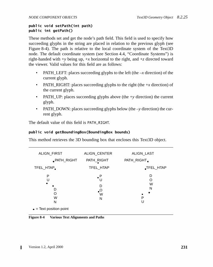
NODE COMPONENT OBJECTS Text3D Geometry Object8.2.25
how(seet3Ds”) is
.
public void setPath(int path)public int getPath()
These methods set and get the node’s path field. This field is used to specifysucceeding glyphs in the string are placed in relation to the previous glyphFigure 8-4). The path is relative to the local coordinate system of the Texnode. The default coordinate system (see Section 4.4, “Coordinate Systemright-handed with +y being up, +x horizontal to the right, and +z directed towardthe viewer. Valid values for this field are as follows:
• PATH_LEFT: places succeeding glyphs to the left (the –x direction) of thecurrent glyph.
• PATH_RIGHT: places succeeding glyphs to the right (the +x direction) ofthe current glyph.
• PATH_UP: places succeeding glyphs above (the +y direction) the currentglyph.
• PATH_DOWN: places succeeding glyphs below (the –y direction) the cur-rent glyph.
The default value of this field isPATH_RIGHT.
public void getBoundingBox(BoundingBox bounds)
This method retrieves the 3D bounding box that encloses this Text3D object
Figure 8-4 Various Text Alignments and Paths
..
.
.. .
ALIGN_FIRST ALIGN_CENTER ALIGN_LAST
PATH_RIGHT PATH_RIGHT PATH_RIGHT
TFEL_HTAP TFEL_HTAP TFEL_HTAP
= Text position point
PU
PU
PU
DOWN
DOWN
DOWN
231Version 1.2, April 2000
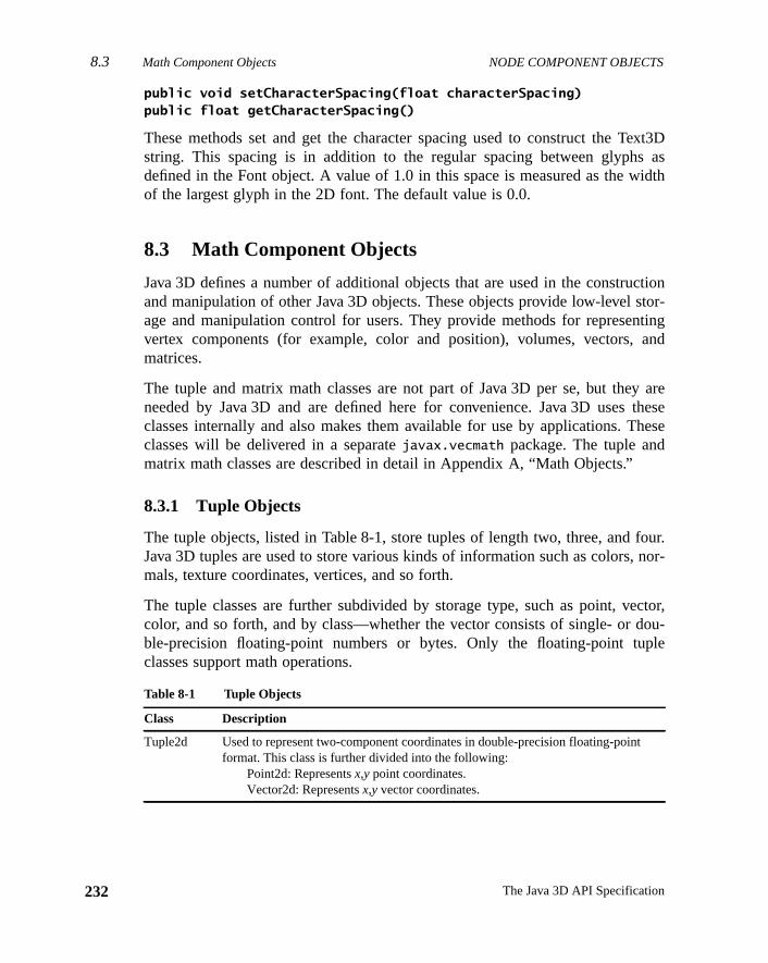
8.3 Math Component Objects NODE COMPONENT OBJECTS
232
ext3Das
idth
ctiontor-tingand
y arethesehese
our.nor-
ctor,ou-
ple
t
public void setCharacterSpacing(float characterSpacing)public float getCharacterSpacing()
These methods set and get the character spacing used to construct the Tstring. This spacing is in addition to the regular spacing between glyphsdefined in the Font object. A value of 1.0 in this space is measured as the wof the largest glyph in the 2D font. The default value is 0.0.
8.3 Math Component Objects
Java 3D defines a number of additional objects that are used in the construand manipulation of other Java 3D objects. These objects provide low-level sage and manipulation control for users. They provide methods for represenvertex components (for example, color and position), volumes, vectors,matrices.
The tuple and matrix math classes are not part of Java 3D per se, but theneeded by Java 3D and are defined here for convenience. Java 3D usesclasses internally and also makes them available for use by applications. Tclasses will be delivered in a separatejavax.vecmath package. The tuple andmatrix math classes are described in detail in Appendix A, “Math Objects.”
8.3.1 Tuple Objects
The tuple objects, listed in Table 8-1, store tuples of length two, three, and fJava 3D tuples are used to store various kinds of information such as colors,mals, texture coordinates, vertices, and so forth.
The tuple classes are further subdivided by storage type, such as point, vecolor, and so forth, and by class—whether the vector consists of single- or dble-precision floating-point numbers or bytes. Only the floating-point tuclasses support math operations.
Table 8-1 Tuple Objects
Class Description
Tuple2d Used to represent two-component coordinates in double-precision floating-poinformat. This class is further divided into the following:
Point2d: Representsx,y point coordinates.Vector2d: Representsx,y vector coordinates.
The Java 3D API Specification
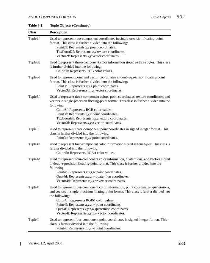
NODE COMPONENT OBJECTS Tuple Objects8.3.1
class
t
, ande
This
ss is
tored
ons,to
his
Tuple2f Used to represent two-component coordinates in single-precision floating-pointformat. This class is further divided into the following:
Point2f: Representsx,y point coordinates.TexCoord2f: Representsx,y texture coordinates.Vector2f: Representsx,y vector coordinates.
Tuple3b Used to represent three-component color information stored as three bytes. Thisis further divided into the following:
Color3b: Represents RGB color values.
Tuple3d Used to represent point and vector coordinates in double-precision floating-poinformat. This class is further divided into the following:
Point3d: Representsx,y,z point coordinates.Vector3d: Representsx,y,z vector coordinates.
Tuple3f Used to represent three-component colors, point coordinates, texture coordinatesvectors in single-precision floating-point format. This class is further divided into thfollowing:
Color3f: Represents RGB color values.Point3f: Representsx,y,z point coordinates.TexCoord3f: Representsx,y,z texture coordinates.Vector3f: Representsx,y,z vector coordinates.
Tuple3i Used to represent three-component point coordinates in signed integer format. class is further divided into the following:
Point3i: Representsx,y,z point coordinates.
Tuple4b Used to represent four-component color information stored as four bytes. This clafurther divided into the following:
Color4b: Represents RGBα color values.
Tuple4d Used to represent four-component color information, quaternions, and vectors sin double-precision floating-point format. This class is further divided into thefollowing:
Point4d: Representsx,y,z,w point coordinates.Quat4d: Representsx,y,z,w quaternion coordinates.Vector4d: Representsx,y,z,w vector coordinates.
Tuple4f Used to represent four-component color information, point coordinates, quaterniand vectors in single-precision floating-point format. This class is further divided inthe following:
Color4f: Represents RGBα color values.Point4f: Representsx,y,z,w point coordinates.Quat4f: Representsx,y,z,w quaternion coordinates.Vector4f: Representsx,y,z,w vector coordinates.
Tuple4i Used to represent four-component point coordinates in signed integer format. Tclass is further divided into the following:
Point4i: Representsx,y,z,w point coordinates.
Table 8-1 Tuple Objects (Continued)
Class Description
233Version 1.2, April 2000
8.3.2 Matrix Objects NODE COMPONENT OBJECTS
234
one
ision
sion
ass.
These are described in more detail in Appendix A, “Math Objects.”
8.3.2 Matrix Objects
The matrix objects, listed in Table 8-2, define a complete 3× 3 or 4× 4 floating-point transformation matrix. All the vector subclasses operate using thismatrix type.
These are described in more detail in Appendix A, “Math Objects.”
AxisAngle4d Used to represent four-component axis-angle rotations consisting of double-precfloating-pointx, y, andz coordinates and a rotation angle in radians.
AxisAngle4f Used to represent four-component axis-angle rotations consisting of single-precifloating pointx, y, andz coordinates and a rotation angle in radians.
GVector Used to represent a general, dynamically resizeable, one-dimensional vector cl
Table 8-2 Matrix Objects
Class Description
Matrix3d Used to represent a double-precision floating-point 3× 3 matrix.
Matrix3f Used to represent a single-precision floating-point 3× 3 matrix.
Matrix4d Used to represent a double-precision floating-point 4× 4 matrix.
Matrix4f Used to represent a single-precision floating-point 4× 4 matrix.
GMatrix A double-precision, general, dynamically resizeableN × M matrix class.
Table 8-1 Tuple Objects (Continued)
Class Description
The Java 3D API Specification
Version 1.2, April 2000
C H A P T E R 9
e,s-of-ery-ttenplaylayh. Itren-
ker to
tualtionvir-hat’sthisent,
omeates
thea
hetor’s
View Model
JAVA 3D introduces a new view model that takes Java’s vision of “write oncrun anywhere” and generalizes it to include display devices and six-degreefreedom input peripherals such as head trackers. This “write once, view evwhere” nature of the new view model means that an application or applet wriusing the Java 3D view model can render images to a broad range of disdevices, including standard computer displays, multiple-projection disprooms, and head-mounted displays, without modification of the scene grapalso means that the same application, once again without modification, cander stereoscopic views and can take advantage of the input from a head traccontrol the rendered view.
Java 3D’s view model achieves this versatility by cleanly separating the virand the physical world. This model distinguishes between how an applicapositions, orients, and scales a ViewPlatform object (a viewpoint) within thetual world and how the Java 3D renderer constructs the final view from tviewpoint’s position and orientation. The application controls the ViewPlatformposition and orientation; the renderer computes what view to render usingposition and orientation, a description of the end-user’s physical environmand the user’s position and orientation within the physical environment.
This chapter first explains why Java 3D chose a different view model and sof the philosophy behind that choice. It next describes how that model operin the simple case of a standard computer screen without head tracking—most common case. Finally, it presents the relevant parts of the API fromdeveloper’s perspective. Appendix C, “View Model Details,” describes tJava 3D view model from an advanced developer and Java 3D implemenperspective.
235
9.1 Why a New Model? VIEW MODEL
236
trolppli-plica-s aseven
manlate
noion
t andera-ereo
ys-s.
theionforvary
as ad aer’senentrs,
s ofill
es
9.1 Why a New Model?
Camera-based view models, as found in low-level APIs, give developers conover all rendering parameters. This makes sense when dealing with custom acations, less sense when dealing with systems that wish to have broader apbility: systems such as viewers or browsers that load and display whole worlda single unit or systems where the end users view, navigate, display, andinteract with the virtual world.
Camera-based view models emulate a camera in the virtual world, not a huin a virtual world. Developers must continuously reposition a camera to emu“a human in the virtual world.”
The Java 3D view model incorporates head tracking directly, if present, withadditional effort from the developer, thus providing end users with the illusthat they actually exist inside a virtual world.
The Java 3D view model, when operating in a non-head-tracked environmenrendering to a single, standard display, acts very much like a traditional cambased view model, with the added functionality of being able to generate stviews transparently.
9.1.1 The Physical Environment Influences the View
Letting the application control all viewing parameters is not reasonable in stems in which the physical environment dictates some of the view parameter
One example of this is a head-mounted display (HMD), where the optics ofhead-mounted display directly determine the field of view that the applicatshould use. Different HMDs have different optics, making it unreasonableapplication developers to hard-wire such parameters or to allow end users tothat parameter at will.
Another example is a system that automatically computes view parametersfunction of the user’s current head position. The specification of a world anpredefined flight path through that world may not exactly specify an end-usview. HMD users would expect to look and thus see to their left or right evwhen following a fixed path through the environment—imagine an amusempark ride with vehicles that follow fixed paths to present content to their visitobut visitors can continue to move their heads while on those rides.
Depending on the physical details of the end-user’s environment, the valuethe viewing parameters, particularly the viewing and projection matrices, wvary widely. The factors that influence the viewing and projection matric
The Java 3D API Specification
VIEW MODEL The Physical World 9.2.2
er’sthreeanddel
ationenvi-input
ysicall-actionctiv-
alcaletstiveen-raph
ineadocaled.
iffer-dif-re isdi-er (if
include the size of the physical display, how the display is mounted (on the ushead or on a table), whether the computer knows the user’s head location inspace, the head mount’s actual field of view, the display’s pixels per inch,other such parameters. For more information, see Appendix C, “View MoDetails.”
9.2 Separation of Physical and Virtual
The Java 3D view model separates the virtual environment, where the applicprogrammer has placed objects in relation to one another, from the physicalronment, where the user exists, sees computer displays, and manipulatesdevices.
Java 3D also defines a fundamental correspondence between the user’s phworld and the virtual world of the graphic application. This physical-to-virtuaworld correspondence defines a single common space, a space where antaken by an end user affects objects within the virtual world and where any aity by objects in the virtual world affects the end user’s view.
9.2.1 The Virtual World
The virtual world is a common space in which virtual objects exist. The virtuworld coordinate system exists relative to a high-resolution Locale—each Loobject defines the origin of virtual world coordinates for all of the objecattached to that Locale. The Locale that contains the currently acViewPlatform object defines the virtual world coordinates that are used for rdering. Java3D eventually transforms all coordinates associated with scene gelements into this common virtual world space.
9.2.2 The Physical World
The physical world is just that—the real, physical world. This is the spacewhich the physical user exists and within which he or she moves his or her hand hands. This is the space in which any physical trackers define their lcoordinates and in which several calibration coordinate systems are describ
The physical world is a space, not a common coordinate system between dent execution instances of Java 3D. So while two different computers at twoferent physical locations on the globe may be running at the same time, theno mechanism directly within Java 3D to relate their local physical world coornate systems with each other. Because of calibration issues, the local track
237Version 1.2, April 2000
9.3 The Objects That Define the View VIEW MODEL
238
ular
cally,ject,ject.
sid-
Fortualardtails
hein
any) defines the local physical world coordinate system known to a particinstance of Java 3D.
9.3 The Objects That Define the View
Java 3D distributes its view model parameters across several objects, specifithe View object and its associated component objects, the PhysicalBody obthe PhysicalEnvironment object, the Canvas3D object, and the Screen3D obFigure 9-1 shows graphically the central role of the View object and the subiary role of its component objects.
Figure 9-1 View Object, Its Component Objects, and Their Interconnection
The view-related objects shown in Figure 9-1 and their roles are as follows.each of these objects, the portion of the API that relates to modifying the virworld and the portion of the API that is relevant to non-head-tracked standdisplay configurations are derived in this chapter. The remainder of the deare described in Appendix C, “View Model Details.”
• ViewPlatform: A leaf node that locates a view within a scene graph. TViewPlatform’s parents specify its location, orientation, and scale with
Virtual universe
Hi-res locale
BG
View Canvas3D Screen3D
ViewPlatform
VP
PhysicalBody
PhysicalEnvironment
The Java 3D API Specification
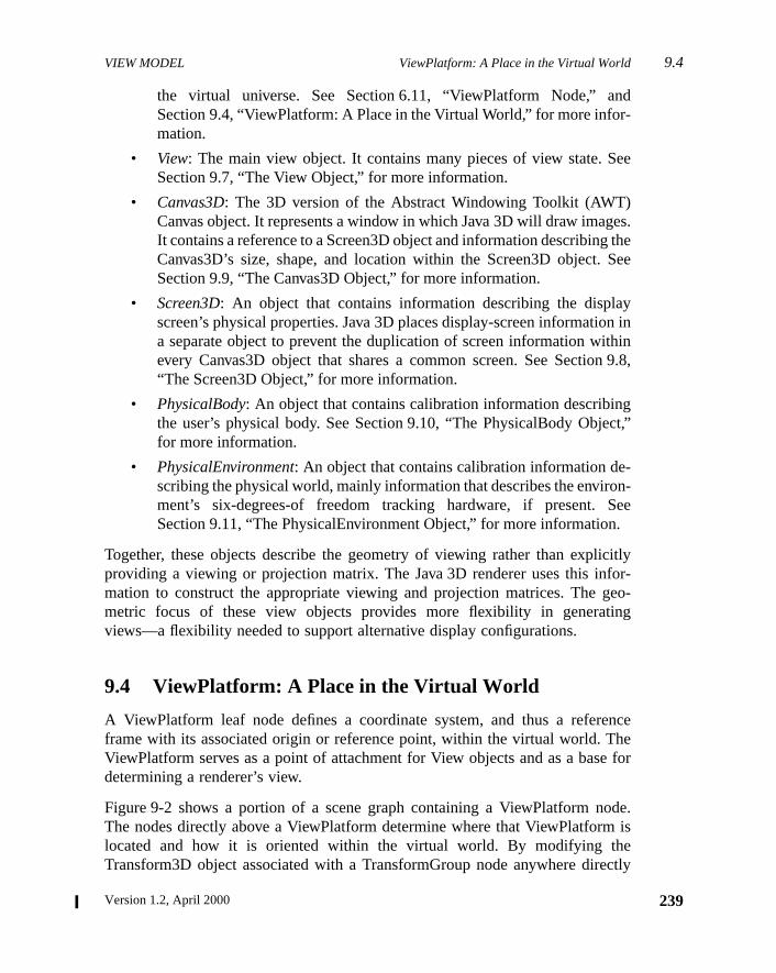
VIEW MODEL ViewPlatform: A Place in the Virtual World 9.4
nd-
ee
es.the
See
yn inhinn 9.8,
gct,”
-n-ee.
citlyfor-eo-
ng
ncehee for
de.is
ectly
the virtual universe. See Section 6.11, “ViewPlatform Node,” aSection 9.4, “ViewPlatform: A Place in the Virtual World,” for more information.
• View: The main view object. It contains many pieces of view state. SSection 9.7, “The View Object,” for more information.
• Canvas3D: The 3D version of the Abstract Windowing Toolkit (AWT)Canvas object. It represents a window in which Java 3D will draw imagIt contains a reference to a Screen3D object and information describingCanvas3D’s size, shape, and location within the Screen3D object.Section 9.9, “The Canvas3D Object,” for more information.
• Screen3D: An object that contains information describing the displascreen’s physical properties. Java 3D places display-screen informatioa separate object to prevent the duplication of screen information witevery Canvas3D object that shares a common screen. See Sectio“The Screen3D Object,” for more information.
• PhysicalBody: An object that contains calibration information describinthe user’s physical body. See Section 9.10, “The PhysicalBody Objefor more information.
• PhysicalEnvironment: An object that contains calibration information describing the physical world, mainly information that describes the enviroment’s six-degrees-of freedom tracking hardware, if present. SSection 9.11, “The PhysicalEnvironment Object,” for more information
Together, these objects describe the geometry of viewing rather than expliproviding a viewing or projection matrix. The Java 3D renderer uses this inmation to construct the appropriate viewing and projection matrices. The gmetric focus of these view objects provides more flexibility in generativiews—a flexibility needed to support alternative display configurations.
9.4 ViewPlatform: A Place in the Virtual World
A ViewPlatform leaf node defines a coordinate system, and thus a refereframe with its associated origin or reference point, within the virtual world. TViewPlatform serves as a point of attachment for View objects and as a basdetermining a renderer’s view.
Figure 9-2 shows a portion of a scene graph containing a ViewPlatform noThe nodes directly above a ViewPlatform determine where that ViewPlatformlocated and how it is oriented within the virtual world. By modifying thTransform3D object associated with a TransformGroup node anywhere dire
239Version 1.2, April 2000
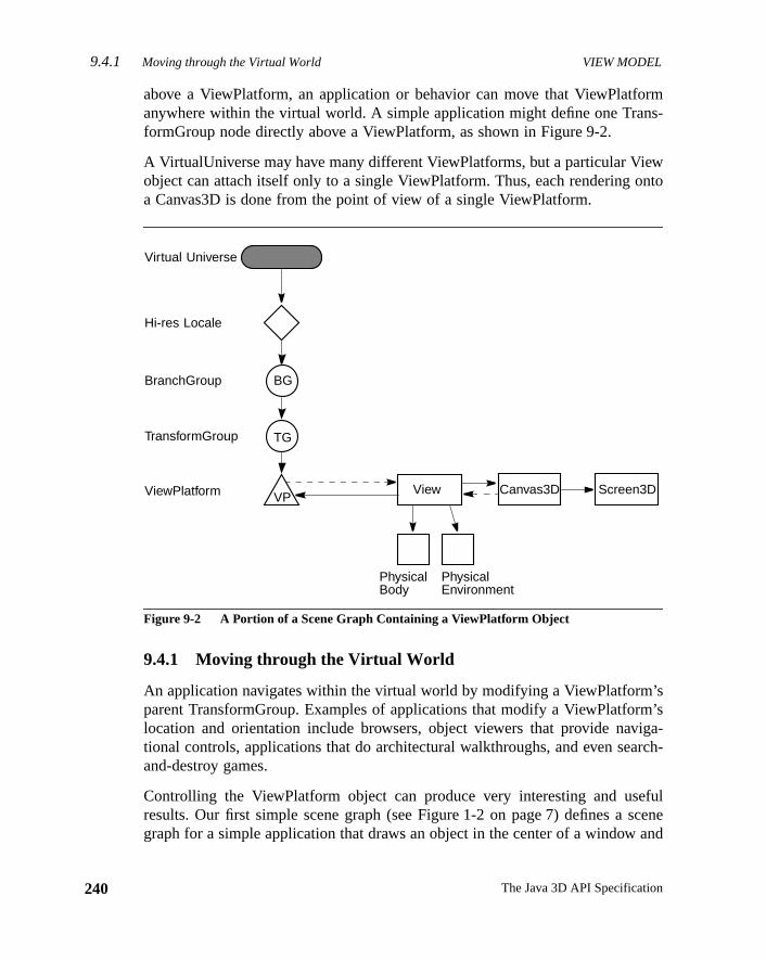
9.4.1 Moving through the Virtual World VIEW MODEL
240
rms-
wnto
’sm’siga-rch-
fulsceneand
above a ViewPlatform, an application or behavior can move that ViewPlatfoanywhere within the virtual world. A simple application might define one TranformGroup node directly above a ViewPlatform, as shown in Figure 9-2.
A VirtualUniverse may have many different ViewPlatforms, but a particular Vieobject can attach itself only to a single ViewPlatform. Thus, each rendering oa Canvas3D is done from the point of view of a single ViewPlatform.
Figure 9-2 A Portion of a Scene Graph Containing a ViewPlatform Object
9.4.1 Moving through the Virtual World
An application navigates within the virtual world by modifying a ViewPlatformparent TransformGroup. Examples of applications that modify a ViewPlatforlocation and orientation include browsers, object viewers that provide navtional controls, applications that do architectural walkthroughs, and even seaand-destroy games.
Controlling the ViewPlatform object can produce very interesting and useresults. Our first simple scene graph (see Figure 1-2 on page 7) defines agraph for a simple application that draws an object in the center of a window
PhysicalBody
PhysicalEnvironment
BG
View Screen3D
TG
Canvas3DVP
Virtual Universe
Hi-res Locale
BranchGroup
TransformGroup
ViewPlatform
The Java 3D API Specification
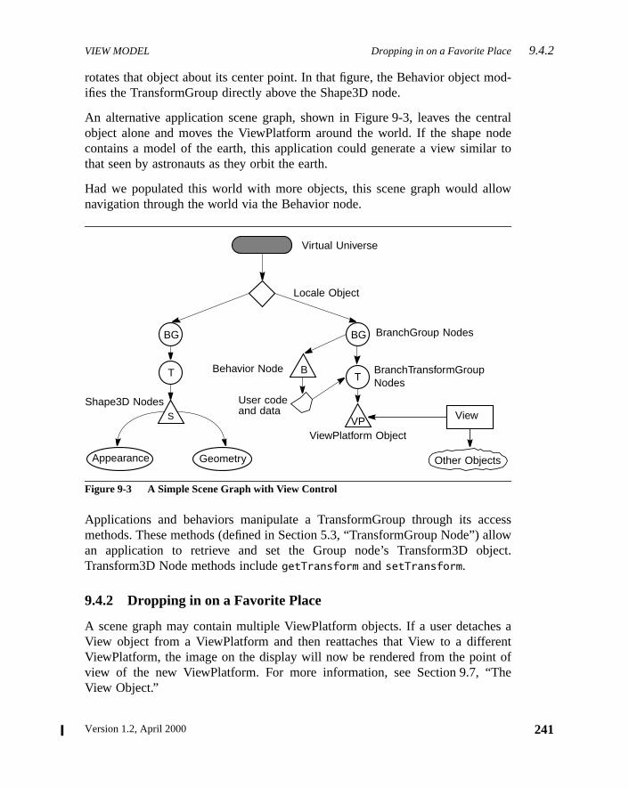
VIEW MODEL Dropping in on a Favorite Place 9.4.2
od-
ntraloder to
low
cessllowect.
es antof
he
rotates that object about its center point. In that figure, the Behavior object mifies the TransformGroup directly above the Shape3D node.
An alternative application scene graph, shown in Figure 9-3, leaves the ceobject alone and moves the ViewPlatform around the world. If the shape ncontains a model of the earth, this application could generate a view similathat seen by astronauts as they orbit the earth.
Had we populated this world with more objects, this scene graph would alnavigation through the world via the Behavior node.
Figure 9-3 A Simple Scene Graph with View Control
Applications and behaviors manipulate a TransformGroup through its acmethods. These methods (defined in Section 5.3, “TransformGroup Node”) aan application to retrieve and set the Group node’s Transform3D objTransform3D Node methods includegetTransform andsetTransform.
9.4.2 Dropping in on a Favorite Place
A scene graph may contain multiple ViewPlatform objects. If a user detachView object from a ViewPlatform and then reattaches that View to a differeViewPlatform, the image on the display will now be rendered from the pointview of the new ViewPlatform. For more information, see Section 9.7, “TView Object.”
S
Virtual Universe
Locale Object
BranchGroup Nodes
BranchTransformGroupNodes
Behavior Node
Shape3D Nodes
Appearance Geometry
User codeand data
ViewPlatform Object
View
Other Objects
BG
T
BG
BT
VP
241Version 1.2, April 2000
9.4.3 View Attach Policy VIEW MODEL
242
olicyes
licy.
he
i-o-
iseed
alatethe
ysal-int.by
10,
-est.e-l vir-by
9.4.3 View Attach Policy
The actual view that Java 3D’s renderer draws depends on the view attach pspecified within the currently attached ViewPlatform. The ViewPlatform definthe following methods for setting and retrieving the view attach policy:
Methods
public void setViewAttachPolicy(int policy)public int getViewAttachPolicy()
These methods set and retrieve the coexistence center in virtual world poThe default attach policy isView.NOMINAL_HEAD. A ViewPlatform’sview attachpolicy determines how Java 3D places the virtual eyepoint within tViewPlatform. The policy can have one of the following values:
• View.NOMINAL_HEAD: Ensures that the end user’s nominal eye postion in the physical world corresponds to the virtual eye’s nominal eye psition in the virtual world (the ViewPlatform’s origin). In essence, thpolicy tells Java 3D to position the virtual eyepoint relative to thViewPlatform origin in the same way as the physical eyepoint is positionrelative to its nominal physical-world origin. Deviations in the physiceye’s position and orientation from nominal in the physical world genercorresponding deviations of the virtual eye’s position and orientation invirtual world.
• View.NOMINAL_FEET: Ensures that the end user’s virtual feet alwatouch the virtual ground. This policy tells Java 3D to compute the physicto-virtual-world correspondence in a way that enforces this constraJava 3D does so by appropriately offsetting the physical eye’s positionthe end-user’s physical height. Java 3D uses thenominalEyeHeightFrom-
Ground parameter found in the PhysicalBody object (see Section 9.“The PhysicalBody Object”) to perform this computation.
• View.NOMINAL_SCREEN: Allows an application always to have the virtual eyepoint appear at some “viewable” distance from a point of interThis policy tells Java 3D to compute the physical-to-virtual-world corrspondence in a way that ensures that the renderer moves the nominatual eyepoint away from the point of interest by the amount specifiedthenominalEyeOffsetFromNominalScreen parameter found in the Phys-icalBody object (see Section 9.10, “The PhysicalBody Object”).
The Java 3D API Specification

VIEW MODEL Composing Model and Viewing Transformations9.5.1
sta-
ucts.
roupr theode
ouldn alnow
sys-
g oniron-puta-uterel
tualionererctionng
a 3Dtionom-
and—the
9.4.4 Associating Geometry with a ViewPlatform
Java 3D does not have any built-in semantics for displaying a visible manifetion of a ViewPlatform within the virtual world (anavatar). However, a devel-oper can construct and manipulate an avatar using standard Java 3D constr
A developer can construct a small scene graph consisting of a TransformGnode, a behavior leaf node, and a shape node and insert it directly undeBranchGroup node associated with the ViewPlatform object. The shape nwould contain a geometric model of the avatar’s head. The behavior node wchange the TransformGroup’s transform periodically to the value stored iView object’s UserHeadToVworld parameter (see Appendix C, “View ModeDetails”). The avatar’s virtual head, represented by the shape node, willmove around in lock-step with the ViewPlatform’s TransformGroupandany rel-ative position and orientation changes of the user’s actual physical head (if atem has a head tracker).
9.5 Generating a View
Java 3D generates viewing matrices in one of a few different ways, dependinwhether the end user has a head-mounted or a room-mounted display envment and whether head tracking is enabled. This section describes the comtion for a non-head-tracked, room-mounted display—a standard compdisplay. Other environments are described in Appendix C, “View ModDetails.”
In the absence of head tracking, the ViewPlatform’s origin specifies the vireye’s location and orientation within the virtual world. However, the eye locatprovides only part of the information needed to render an image. The rendalso needs a projection matrix. In the default mode, Java 3D uses the projepolicy, the specified field-of-view information, and the front and back clippidistances to construct a viewing frustum.
9.5.1 Composing Model and Viewing Transformations
Figure 9-4 shows a simple scene graph. To draw the object labeled “S,” Javinternally constructs the appropriate model, view platform, eye, and projecmatrices. Conceptually, the model transformation for a particular object is cputed by concatenating all the matrices in a direct path between the objectthe VirtualUniverse. The view matrix is then computed—again, conceptuallyby concatenating all the matrices between the VirtualUniverse object and
243Version 1.2, April 2000
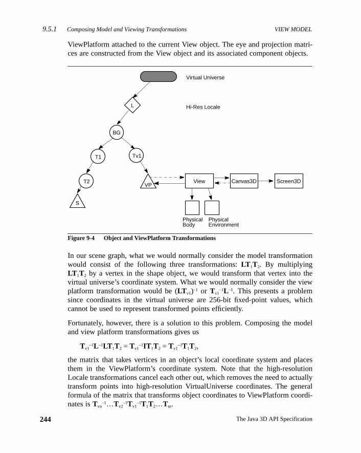
9.5.1 Composing Model and Viewing Transformations VIEW MODEL
244
tri-cts.
tion
theiew
ich
odel
acesiontuallyeraldi-
ViewPlatform attached to the current View object. The eye and projection maces are constructed from the View object and its associated component obje
Figure 9-4 Object and ViewPlatform Transformations
In our scene graph, what we would normally consider the model transformawould consist of the following three transformations:LT 1T2. By multiplyingLT 1T2 by a vertex in the shape object, we would transform that vertex intovirtual universe’s coordinate system. What we would normally consider the vplatform transformation would be (LT v1)–1 or Tv1
–1L –1. This presents a problemsince coordinates in the virtual universe are 256-bit fixed-point values, whcannot be used to represent transformed points efficiently.
Fortunately, however, there is a solution to this problem. Composing the mand view platform transformations gives us
Tv1–1L –1LT 1T2 = Tv1
–1IT 1T2 = Tv1–1T1T2,
the matrix that takes vertices in an object’s local coordinate system and plthem in the ViewPlatform’s coordinate system. Note that the high-resolutLocale transformations cancel each other out, which removes the need to actransform points into high-resolution VirtualUniverse coordinates. The genformula of the matrix that transforms object coordinates to ViewPlatform coornates isTvn
–1…Tv2–1Tv1
–1T1T2…Tm.
BG
VP
Virtual Universe
Hi-Res Locale
View Canvas3D Screen3D
PhysicalBody
PhysicalEnvironment
T1
T2
S
Tv1
L
The Java 3D API Specification
VIEW MODEL Multiple Locales 9.5.2
for-
sys-teder-
calesthat
s theles
am-the
es in
ns-irtu-
y
iven, the
s.
olu-e areques
As mentioned earlier, the View object contains the remainder of the view inmation, specifically, the eye matrix,E, that takes points in the ViewPlatform’slocal coordinate system and translates them into the user’s eye coordinatetem, and the projection matrix,P, that projects objects in the eye’s coordinasystem into clipping coordinates. The final concatenation of matrices for rening our shape object “S” on the specified Canvas3D isPETv1
–1T1T2. In generalthis isPETvn
–1…Tv2–1Tv1
–1T1T2…Tm.
The details of how Java 3D constructs the matricesE andP in different end-userconfigurations are described in Appendix C, “View Model Details.”
9.5.2 Multiple Locales
Java 3D supports multiple high-resolution Locales. In some cases, these Loare close enough to each other that they can “see” each other, meaningobjects can be rendered even though they are not in the same Locale aViewPlatform object that is attached to the View. Java 3D automatically handthis case without the application having to do anything. As in the previous exple, where the ViewPlatform and the object being rendered are attached tosame Locale, Java 3D internally constructs the appropriate matrices for caswhich the ViewPlatform and the object being rendered arenot attached to thesame Locale.
Let’s take two Locales, L1 and L2, with the View attached to a ViewPlatform inL1. According to our general formula, the modeling transformation—the traformation that takes points in object coordinates and transforms them into ValUniverse coordinates—isLT 1T2…Tm. In our specific example, a point inLocale L2 would be transformed into VirtualUniverse coordinates bL 2T1T2…Tm. The view platform transformation would be (L 1Tv1Tv1…Tvn)–1 orTvn
–1…Tv2–1Tv1
–1L 1–1. Composing these two matrices gives us
Tvn–1…Tv2
–1Tv1–1L 1
–1L 2T1T2…Tm.
Thus, to render objects in another Locale, it is sufficient to computeL 1–1L 2 and
use that as the starting matrix when composing the model transformations. Gthat a Locale is represented by a single high-resolution coordinate positiontransformationL 1
–1L 2 is a simple translation byL 2 – L 1. Again, it is not actuallynecessary to transform points into high-resolution VirtualUniverse coordinate
In general, Locales that are close enough that the difference in their high-restion coordinates can be represented in double precision by a noninfinite valuclose enough to be rendered. In practice, more sophisticated culling technican be used to render only those Locales that really are “close enough.”
245Version 1.2, April 2000
9.6 A Minimal Environment VIEW MODEL
246
canustent
ion
s allrminets. Itew.
ewiew
e-
9.6 A Minimal Environment
An application must create a minimal set of Java 3D objects before Java 3Drender to a display device. In addition to a Canvas3D object, the application mcreate a View object, with its associated PhysicalBody and PhysicalEnvironmobjects, and the following scene graph elements:
• A VirtualUniverse object
• A high-resolution Locale object
• A BranchGroup node object
• A TransformGroup node object with associated transform
• A ViewPlatform leaf node object that defines the position and orientatwithin the virtual universe for generating views
9.7 The View Object
The View object coordinates all aspects of the rendering process. It containthe parameters or references to objects containing the parameters that detehow to render images to the windows represented by its Canvas3D objecalso contains the set of canvases that represent various “windows” onto a vi
Java 3D allows applications to specify multiple simultaneously active Viobjects, each controlling its own set of canvases. For more details on a Vobject’s internals, see Section C.5, “The View Object.”
Constructors
The View object specifies the following constructor:
public View()
Constructs and initializes a new View object with the following default paramters:
Parameter Default Value
view policy SCREEN_VIEW
projection policy PERSPECTIVE_PROJECTION
screen scale policy SCALE_SCREEN_SIZE
window resize policy PHYSICAL_WORLD
window movement policy PHYSICAL_WORLD
window eyepoint policy RELATIVE_TO_FIELD_OF_VIEW
The Java 3D API Specification

VIEW MODEL The View Object 9.7
Methods
The View object specifies the following methods:
monoscopic view policy(deprecated in this class)
CYCLOPEAN_EYE_VIEW
front clip policy PHYSICAL_EYE
back clip policy PHYSICAL_EYE
visibility policy VISIBILITY_DRAW_VISIBLE
coexistence centering flag true
compatibility mode false
left projection identity
right projection identity
vpc to ec transform identity
physical body null
physical environment null
screen scale 1.0
field of view π/4
left manual eye in coexistence (-0.033, 0.0, 0.4572)
right manual eye in coexistence (0.033, 0.0, 0.4572)
front clip distance 0.1
back clip distance 10.0
tracking enable false
user head to vworld enable false
list of Canvas3D objects empty
depth buffer freeze transparent true
scene antialiasing false
local eye lighting false
view platform null
behavior scheduler running true
view running true
minimum frame duration 0
Parameter Default Value
247Version 1.2, April 2000
9.7 The View Object VIEW MODEL
248
Seeal-
Seehe
ist-e-iew
g a
ulta-was
livea-
bjectthinion
public void setPhysicalBody(PhysicalBody physicalBody)public PhysicalBody getPhysicalBody()
These methods set and retrieve the View’s PhysicalBody object.Section 9.10, “The PhysicalBody Object,” for more information on the PhysicBody object.
public void setPhysicalEnvironment(PhysicalEnvironment physicalEnvironment)public PhysicalEnvironment getPhysicalEnvironment()
These methods set and retrieve the View’s PhysicalEnvironment object.Section 9.11, “The PhysicalEnvironment Object,” for more information on tPhysicalEnvironment object.
public void attachViewPlatform(ViewPlatform vp)
This method attaches a ViewPlatform leaf node to this View, replacing the exing ViewPlatform. If the ViewPlatform is part of a live scene graph, or is subsquently made live, the scene graph is rendered into all canvases in this Vobject’s list of Canvas3D objects. To remove a ViewPlatform without attachinnew one—causing the View to no longer be rendered—anull reference may bepassed to this method. In this case, the behavior is as if rendering were simneously stopped on all canvases attached to the View—the last frame thatrendered in each remains visible until the View is again attached to aViewPlatform object. See Section 6.11, “ViewPlatform Node,” for more informtion on ViewPlatform objects.
public ViewPlatform getViewPlatform()
This method retrieves the currently attached ViewPlatform object.
public Canvas3D getCanvas3D(int index)public void setCanvas3D(Canvas3D canvas3D, int index)public void addCanvas3D(Canvas3D canvas3D)public void insertCanvas3D(Canvas3D canvas3D, int index)public void removeCanvas3D(int index)public void removeCanvas3D(Canvas3D canvas3D)
These methods set, retrieve, add to, insert after, and remove a Canvas3D ofrom this View. The index specifies the reference to the Canvas3D object withe View object. See Section 9.9, “The Canvas3D Object” for more informaton Canvas3D objects.
The Java 3D API Specification
VIEW MODEL Projection Policy 9.7.1
ro-iew
iew.
a
te a
atesjec-n
us-t
dow
le.
ew in 1.2
public int numCanvas3Ds()This method returns the the number of Canvas3Ds in this View.
public Enumeration getAllCanvas3Ds()
This method gets the Enumeration object of all the Canvas3Ds.
9.7.1 Projection Policy
The projection policy informs Java 3D whether it should generate a parallel pjection or a perspective projection. This policy is attached to the Java 3D Vobject.
Methods
public void setProjectionPolicy(int policy)public int getProjectionPolicy()
These two methods set and retrieve the current projection policy for this vThe projection policies are as follows:
• PARALLEL_PROJECTION: Specifies that Java 3D should computeparallel projection.
• PERSPECTIVE_PROJECTION: Specifies that Java 3D should compuperspective projection. This is the default setting.
public void setLocalEyeLightingEnable(boolean flag)public boolean getLocalEyeLightingEnable()
These methods set and retrieve the local eye lighting flag, which indicwhether the local eyepoint is used in lighting calculations for perspective protions. If this flag is set totrue, the view vector is calculated per vertex based othe direction from the actual eyepoint to the vertex. If this flag is set tofalse, asingle view vector is computed from the eyepoint to the center of the view frtum. This is calledinfinite eye lighting. Local eye lighting is disabled by defauland is ignored for parallel projections.
9.7.1.1 Window Sizing and Movement
When users resize or move windows, Java 3D can choose to think of the winas attached either to the physical world or to the virtual world. Thewindowresize policyallows an application to specify how the view model will handresizing requests. The window resize policies are specified by two constants
N
249Version 1.2, April 2000
9.7.1 Projection Policy VIEW MODEL
250
d in
rtual
win-gdsingdow
r aain
omesfault
nc-
rges,. Aein-
angesin
Constants
public static final int PHYSICAL_WORLD
This variable specifies the policy for resizing and moving windows and is usespecifying windowResizePolicy and windowMovementPolicy. This variablespecifies that the specified action takes place only in the physical world.
public static final int VIRTUAL_WORLD
This variable specifies that Java 3D applies the associated policy in the viworld.
Methods
public void setWindowResizePolicy(int policy)public int getWindowResizePolicy()
This variable specifies how Java 3D modifies the view when a user resizes adow. A value ofPHYSICAL_WORLD states that Java 3D will treat window resizinoperations as happeningonly in the physical world. This implies that rendereobjects continue to fill the same percentage of the newly sized window, umore or fewer pixels to draw those objects, depending on whether the wingrew or shrank in size. A value ofVIRTUAL_WORLD states that Java 3D will treatwindow resizing operations as also happening in the virtual world wheneveresizing occurs in the physical world. This implies that rendered objects remthe same size (use the same number of pixels), but since the window beclarger or smaller, the user sees more or less of the virtual world. The devalue isPHYSICAL_WORLD.
public void setWindowMovementPolicy(int policy)public int getWindowMovementPolicy()
This variable specifies what part of the virtual world Java 3D will draw as a fution of the window location on the display screen. A value ofPHYSICAL_WORLD
states that the window acts as if it movesonly on the physical screen. As the usemoves the window on the screen, the window’s position on the screen chanbut Java 3D continues to draw exactly the same image within that windowvalue ofVIRTUAL_WORLD states that the window acts as if it also moves within thvirtual world. As the user moves the window on the physical screen, the wdow’s position on the screen changes, and the image that Java 3D draws chas well to match what would be visible in the virtual world from a windowthat new position. The default value isPHYSICAL_WORLD.
The Java 3D API Specification
VIEW MODEL Projection and Clip Parameters 9.7.3
theyinge vir-lative
ne.
ne.
e’s
theters).
al
hetes.
and
9.7.2 Clip Policies
The clip policies determine how Java 3D interprets clipping distances to bothnear and far clip planes. The policies can contain one of four values specifwhether a distance measurement should be interpreted in the physical or thtual world and whether that distance measurement should be interpreted reto the physical eyepoint or the physical screen.
Methods
public void setFrontClipPolicy(int policy)public int getFrontClipPolicy()public void setBackClipPolicy(int policy)public int getBackClipPolicy()
The front clip policy determines where Java 3D places the front clipping plaThe value is one of the following:PHYSICAL_EYE, PHYSICAL_SCREEN, VIRTUAL_EYE, or VIRTUAL_SCREEN. The default value isPHYSICAL_EYE.
The back clip policydetermines where Java 3D places the back clipping plaThe value is one of the following:PHYSICAL_EYE, PHYSICAL_SCREEN, VIRTUAL_EYE, or VIRTUAL_SCREEN. The default value isPHYSICAL_EYE.
These policies are defined as follows.
• PHYSICAL_EYE: Specifies that the plane is located relative to the eyposition as measured in the physical space (in meters).
• PHYSICAL_SCREEN: Specifies that the plane is located relative toscreen (that is, the image plate) as measured in physical space (in me
• VIRTUAL_EYE: Specifies that the plane is located relative to the virtueyepoint as measured in virtual world coordinates.
• VIRTUAL_SCREEN: Specifies that the plane is located relative to tscreen (that is, the image plate) as measured in virtual world coordina
9.7.3 Projection and Clip Parameters
The projection and clip parameters determine the view model’s field of viewthe front and back clipping distances.
251Version 1.2, April 2000
9.7.3 Projection and Clip Parameters VIEW MODEL
252
ori-islicy
ronting.arepec-
acking.is-
rtual)ct’sode
hoos-
rdi-
atys-
less
e in
eyeut
public void setFieldOfView(double fieldOfView)public double getFieldOfView()
In the default non-head-tracked mode, this value specifies the view model’s hzontal field of view in radians. This value is ignored when the view modeloperating in head-tracked mode or when the Canvas3D’s window eyepoint pois set to a value other than the default setting ofRELATIVE_TO_FIELD_OF_VIEW
(see Section C.5.3, “Window Eyepoint Policy”).
public void setFrontClipDistance(double distance)public double getFrontClipDistance()
This value specifies the distance away from the clip origin, specified by the fclip policy variable, in the direction of gaze where objects stop disappearObjects closer than the clip origin (eye or screen) plus the front clip distancenot drawn. Measurements are done in the space (physical or virtual) that is sified by the associated front clip policy parameter.
public void setBackClipDistance(double distance)public double getBackClipDistance()
This value specifies the distance away from the clip origin (specified by the bclip policy variable) in the direction of gaze where objects begin disappearObjects farther away from the clip origin (eye or screen) plus the back clip dtance are not drawn. Measurements are done in the space (physical or vithat is specified by the associated back clip policy parameter. The View objeback clip distance is ignored if the scene graph contains an active Clip leaf n(see Section 6.5, “Clip Node”).
There are several considerations that need to be taken into account when cing values for the front and back clip distances.
• The front clip distance must be greater than 0.0 in physical eye coonates.
• The front clipping plane must be in front of the back clipping plane; this, the front clip distance must be less than the back clip distance in phical eye coordinates.
• The front and back clip distances, in physical eye coordinates, must bethan the largest positive single-precision floating-point value,Float.MAX_
VALUE. In practice, since these physical eye coordinate distances armeters, the values should bemuch less than that.
• The ratio of the back distance divided by the front distance, in physicalcoordinates, affectsz-buffer precision. This ratio should be less than abo
The Java 3D API Specification
VIEW MODEL Frame Start Time, Duration, and Number9.7.4
ll
es,
and
d. ItMT.e is
tedw isf the
can-pointme
ts at
r ofran-
dtheon.
3000 to accommodate 16-bitz-buffers. Values of 100 to less than 1000 wiproduce better results.
Violating any of the above rules will result in undefined behavior. In many casno picture will be drawn.
9.7.4 Frame Start Time, Duration, and Number
The following methods are used to get information about system executionperformance:
public long getCurrentFrameStartTime()
This method returns the time at which the most recent rendering frame starteis defined as the number of milliseconds since January 1, 1970, 00:00:00 GSince multiple canvases might be attached to this View, the start of a framdefined as the point just prior to clearing any canvas attached to this View.
public long getLastFrameDuration()
This method returns the duration, in milliseconds, of the most recently complerendering frame. The time taken to render all canvases attached to this Viemeasured. This duration is computed as the difference between the start omost recently completed frame and the end of that frame. Since multiplevases might be attached to this View, the start of a frame is defined as thejust prior to clearing any canvas attached to this View, while the end of a frais defined as the point just after swapping the buffer for all canvases.
public long getFrameNumber()
This method returns the frame number for this view. The frame number star0 and is incremented prior to clearing all the canvases attached to this view.
public static int getMaxFrameStartTimes()
This method retrieves the implementation-dependent maximum numbeframes whose start times will be recorded by the system. This value is guateed to be at least 10 for all implementations of the Java 3D API.
public long getFrameStartTimes(long times[])
This method copies the lastk frame start-time values into the user-specifiearray. The most recent frame start time is copied to location 0 of the array,next most recent frame start time is copied into location 1 of the array, and soIf times.length is smaller than maxFrameStartTimes, only the last
253Version 1.2, April 2000
9.7.5 View Traversal and Behavior Scheduling VIEW MODEL
254
nds,ach.
n of
uledn ther isand
theedulerates
eneciatedg thisview.
run-
tiontrol.
New in 1.2
New in 1.2
times.length values are copied. Iftimes.length is greater thanmaxFrame-StartTimes, all array elements after indexmaxFrameStartTimes – 1 are set to 0.
public void setMinimumFrameCycleTime(long duration)public long getMinimumFrameCycleTime()
These methods set and retrieve the minimum frame cycle time, in millisecofor this view. The Java 3D renderer will ensure that the duration between eframe is at least the specified number of milliseconds. The default value is 0
9.7.5 View Traversal and Behavior Scheduling
The following methods control the traversal, the rendering, and the executiothe behavior scheduler for this view:
public final long[] stopBehaviorScheduler()public final void startBehaviorScheduler()public final boolean isBehaviorSchedulerRunning()
The first method stops the behavior scheduler after all currently schedbehaviors are executed. Any frame-based behaviors scheduled to wake up onext frame will be executed at least once before the behavior schedulestopped. The method returns a pair of integers that specify the beginningending time (in milliseconds since January 1, 1970, 00:00:00 GMT) ofbehavior scheduler’s last pass. The second method starts the behavior schrunning after it has been stopped. The third method retrieves a flag that indicwhether the behavior scheduler is currently running.
public final void stopView()public final void startView()public final boolean isViewRunning()
The first method stops traversing this view after the current state of the scgraph is reflected on all canvases attached to this view. The renderers assowith these canvases are also stopped. The second method starts traversinview and starts the renderers associated with all canvases attached to thisThe third method returns a flag indicating whether the traverser is currentlyning on this view.
Note: The above six methods are heavy-weight methods intended for verificaand image capture (recording). They are not intended to be used for flow con
The Java 3D API Specification
VIEW MODEL Depth Buffer 9.7.7
d is
ossi-If the
aill
wing
ing isbential-
tial-rior
forderedleduffer-his
ew in 1.2
ew in 1.2
public void renderOnce()
This method renders one frame for a stopped View. Functionally, this methoequivalent tostartView() followed by stopview(), except that it is atomic,which guarantees that only one frame is rendered.
public void repaint()
This method requests that this View be scheduled for rendering as soon as pble. The repaint method may return before the frame has been rendered.view is stopped or if the view is continuously running (for example, due tofree-running interpolator), this method will have no effect. Most applications wnot need to call this method, since any update to the scene graph or to vieparameters will automatically cause all affected views to be rendered.
9.7.6 Scene Antialiasing
public void setSceneAntialiasingEnable(boolean flag)public boolean getSceneAntialiasingEnable()
These methods set and retrieve the scene antialiasing flag. Scene antialiaseither enabled or disabled for this view. If enabled, the entire scene willantialiased on each canvas in which scene antialiasing is available. Scene aiasing is disabled by default.
Note: Line and point antialiasing are independent of scene antialiasing. If aniasing is enabled for lines and points, the lines and points will be antialiased pto scene antialiasing.
9.7.7 Depth Buffer
public void setDepthBufferFreezeTransparent(boolean flag)public boolean getDepthBufferFreezeTransparent()
The set method enables or disables automatic freezing of the depth bufferobjects rendered during the transparent rendering pass (that is, objects renusing alpha blending) for this view. If enabled, depth buffer writes are disabduring the transparent rendering pass regardless of the value of the depth-bwrite-enable flag in the RenderingAttributes object for a particular node. Tflag is enabled by default. Theget method retrieves this flag.
N
N
255Version 1.2, April 2000
9.8 The Screen3D Object VIEW MODEL
256
on-tivetipletputthe
ysi-tem.thecal
ibra-
bjectas by
e-
ingrs.
Theject.
New in 1.2
9.8 The Screen3D Object
The Screen3D object provides a 3D version of the AWT screen object. It ctains the screen’s physical properties. Java 3D will support multiple acScreen3D objects as soon as AWT support is available. Of course, mulscreens are available only if the machine configuration has multiple ouscreens. Java 3D primarily needs to know the physical size (in meters) ofScreen3D’s visible, addressable raster (theimage plate) and, in head-trackingmode, the position and orientation of this raster relative to a well-defined phcal world coordinate system, specifically, the tracker base coordinate sysJava 3D also needs to know how many pixels the raster can display in bothxandy dimensions. This information allows Java 3D to calculate a pixel’s physidimension.
Calibration utilities can change a Screen3D’s physical characteristics or caltion transforms. See Section C.6, “The Screen3D Object.”
The Screen3D object has no public constructors. Instead, the Screen3D oassociated with a particular Canvas3D object can be obtained from the canvcalling thegetScreen3D method. See Section 9.9.3, “Other Canvas3D Paramters.”
Default values for Screen3D parameters are as follows:
Methods
These methods provide applications with information concerning the underlydisplay hardware, such as the screen’s width and height in pixels or in mete
public Dimension getSize()public Dimension getSize(Dimension rv)
These methods retrieve the width and height (in pixels) of this Screen3D.second method copies the width and height into the specified Dimension ob
Parameter Default Value
physical screen width 0.0254/90.0 * screen width (in pixels)
physical screen height 0.0254/90.0 * screen height (in pixels)
tracker base to image plate transform identity
head tracker to left image plate transform identity
head tracker to right image plate transform identity
off-screen size (0,0)
The Java 3D API Specification
VIEW MODEL The Canvas3D Object 9.9
ht in
ory
3D.
r ton an
tionste-r forto a
phys-sizethe
ren-likeon-
as3Dsono-
ew in 1.2
ew in 1.2
public double getPhysicalScreenWidth()public double getPhysicalScreenHeight()
These methods retrieve the screen’s (image plate’s) physical width and heigmeters.
9.8.1 Off-Screen Rendering
New for Java 3D 1.2 is an off-screen mode that allows rendering to a memimage, which is possibly larger than the screen.
public void setSize(int width, int height)public void setSize(Dimension d)
These methods set the width and height (in pixels) of this off-screen ScreenThe default size for off-screen Screen3D objects is (0,0).
Note: The off-screen size, physical width, and physical height must be set priorendering to the associated off-screen canvas. Failure to do so will result iexception.
9.9 The Canvas3D Object
The Canvas3D object extends thejava.awt.Canvas object to include 3D-relatedinformation such as the size of the canvas in pixels, the Canvas3D’s loca(also in pixels) within a Screen3D object, and whether or not the canvas hasreo enabled. The Canvas3D class is used either for on-screen rendering ooff-screen rendering. Because all Canvas3D objects contain a referenceScreen3D object and because Screen3D objects define the size of a pixel inical units, Java 3D can convert a Canvas3D size in pixels to a physical worldin meters. It can also determine the Canvas3D’s position and orientation inphysical world.
The Canvas3D class is used either for on-screen rendering or for off-screendering. On-screen Canvas3Ds are added to AWT or Swing Container objectsany other canvas. Java 3D automatically and continuously renders to allscreen canvases that are attached to an active View object. On-screen Canvcan be either single or double buffered and they can be either stereo or mscopic.
N
N
257Version 1.2, April 2000
9.9 The Canvas3D Object VIEW MODEL
258
rs to
uff-reenff-ap”
nderas
nder
heem-
pec-
New in 1.2
Off-screen Canvas3Ds must not be added to any Container. Java 3D rendeoff-screen canvases in response to therenderOffScreenBuffer method (seeSection 9.9.2, “Off-Screen Rendering”). Off-screen Canvas3Ds are single bered. However, on many systems, the actual rendering is done to an off-schardware buffer or to a 3D library-specific buffer and copied only to the oscreen buffer of the Canvas when the rendering is complete, at “buffer swtime. Off-screen Canvas3Ds are monoscopic.
Constructors
The Canvas3D object specifies the following constructors:
public Canvas3D(GraphicsConfiguration graphicsConfiguration)
This constructs and initializes a new Canvas3D object that Java 3D can reinto. The following Canvas3D parameters are initialized to default valuesshown:
public Canvas3D(GraphicsConfiguration graphicsConfiguration, boolean offScreen)
This constructs and initializes a new Canvas3D object that Java 3D can reinto.
Java 3D can render into this Canvas3D object. If thegraphicsConfiguration
argument isnull, a GraphicsConfiguration object will be constructed using tdefault GraphicsConfigTemplate3D (see Section 9.9.4, “GraphicsConfigTplate3D Object”).
For more information on the GraphicsConfiguration object, see the Java 2D sification, which is part of the AWT in JDK 1.2.
Parameter Default Value
left manual eye in image plate (0.142, 0.135, 0.4572)
right manual eye in image plate (0.208, 0.135, 0.4572)
stereo enable true
double buffer enable true
monoscopic view policy View.CYCLOPEAN_EYE_VIEW
off-screen mode false
off-screen buffer null
off-screen location (0,0)
The Java 3D API Specification
VIEW MODEL Off-Screen Rendering 9.9.2
tionto
s3D’s
ory
ifiedge-
riteduffer
n3Dp-
reenchs3D
r theren-
ew in 1.2
ew in 1.2
ew in 1.2
ew in 1.2
9.9.1 Window System–Provided Parameters
Java 3D specifies the size of a Canvas3D in pixels. It extracts this informadirectly from the AWT’s window system. Java 3D allows applications onlyaccess these values, not to change them.
public Dimension getLocationOnScreen()public Dimension getSize()
These methods, inherited from the parent Canvas class, retrieve the Canvascreen position and size in pixels.
9.9.2 Off-Screen Rendering
New for Java 3D 1.2 is an off-screen mode that allows rendering to a memimage, which is possibly larger than the screen.
public boolean isOffScreen()
This method retrieves the state of the renderer for this Canvas3D object.
public void setOffScreenBuffer(ImageComponent2D buffer)public ImageComponent2D getOffScreenBuffer()
The first method sets the off-screen buffer for this Canvas3D. The specimage is written into by the Java 3D renderer. The size of the specified ImaComponent determines the size, in pixels, of this Canvas3D—the size inhefrom Component is ignored. The second method retrieves the off-screen bfor this Canvas3D.
Note: The size, physical width, and physical height of the associated Screemust be set explicitly prior to rendering. Failure to do so will result in an excetion.
public void renderOffScreenBuffer()
This method schedules the rendering of a frame into this Canvas3D’s off-scbuffer. The rendering is done from the point of view of the View object to whithis Canvas3D has been added. No rendering is performed if this Canvaobject has not been added to an active View. This method does not wait forendering to actually happen. An application that wishes to know when thedering is complete must either subclass Canvas3D and override thepostSwap
method or callwaitForOffScreenRendering. An IllegalStateException is
N
N
N
N
259Version 1.2, April 2000
9.9.3 Other Canvas3D Parameters VIEW MODEL
260
hes
hissren-hiseen
s therre-thata-
n iscor-that
ndul if
ntial
New in 1.2
New in 1.2
New in 1.2
New in 1.2
New in 1.2
thrown if this Canvas3D is not in off-screen mode, if either the width or theight of the associated Screen3D’s size is≤ 0, or if the associated Screen3D’physical width or height is≤ 0.
public void waitForOffScreenRendering()
This method waits for this Canvas3D’s off-screen rendering to be done. Tmethod will wait until thepostSwap method of this off-screen Canvas3D hacompleted. If this Canvas3D has not been added to an active view or if thederer is stopped for this Canvas3D, this method will return immediately. Tmethod must not be called from a render callback method of an off-scrCanvas3D.
public void setOffScreenLocation(int x, int y)public void setOffScreenLocation(Point p)
These methods set the location of this off-screen Canvas3D. The location iupper-left corner of the Canvas3D relative to the upper-left corner of the cosponding off-screen Screen3D. The function of these methods is similar toof Component.setLocation for on-screen Canvas3D objects. The default loction is (0,0).
public Point getOffScreenLocation()public Point getOffScreenLocation(Point rv)
These methods retrieve the location of this off-screen Canvas3D. The locatiothe upper-left corner of the Canvas3D relative to the upper-left corner of theresponding off-screen Screen3D. The function of these methods is similar toof Component.getLocation for on-screen Canvas3D objects. The secomethod stores the location in the specified Point object. This method is usefthe caller wants to avoid allocating a new Point object on the heap.
9.9.3 Other Canvas3D Parameters
public boolean getStereoAvailable()
This method specifies whether the underlying hardware supports field-sequestereo on this canvas. This is equivalent to
((Boolean)queryProperties().get("stereoAvailable")).booleanValue()
The Java 3D API Specification
VIEW MODEL Other Canvas3D Parameters 9.9.3
s ste-f the
ffer-
dou-fera 3D
level
thatcts.ring
ew in 1.2
public boolean getStereoEnable()public void setStereoEnable(boolean flag)
These methods set or retrieve the flag indicating whether this Canvas3D hareo enabled. If enabled, Java 3D generates left and right eye images. ICanvas3D’sStereoAvailable flag isfalse, Java 3D displays only theleft eye’sview even if an application setsStereoEnable to true. This parameter allowsapplications to enable or disable stereo on a canvas-by-canvas basis.
public void getDoubleBufferAvailable()
This method specifies whether the underlying hardware supports double buing on this canvas. This is equivalent to
((Boolean)queryProperties().get("doubleBufferAvailable")).booleanValue()
public boolean getDoubleBufferEnable()public void setDoubleBufferEnable(boolean flag)
These methods set or retrieve the flag indicating whether this Canvas3D hasble buffering enabled. If disabled, all drawing is to the front buffer, and no bufswap will be done between frames. It should be stressed that running Javwith double buffering disabled is not recommended.
public boolean getSceneAntialiasingAvailable()
This method specifies whether the underlying hardware supports scene-antialiasing on this canvas. This is equivalent to
((Boolean)queryProperties().get("sceneAntialiasingAvailable")).booleanValue()
public View getView()
Retrieves the View object that points to this Canvas3D.
public Screen3D getScreen3D()
Retrieves the Screen3D object to which this Canvas3D is attached.
public final Map queryProperties()
This method returns a read-only Map object containing key-value pairsdefine various properties for this Canvas3D. All of the keys are String objeThe values are key-specific, but most will be Boolean, Integer, Double, or Stobjects. The currently-defined keys are
N
261Version 1.2, April 2000
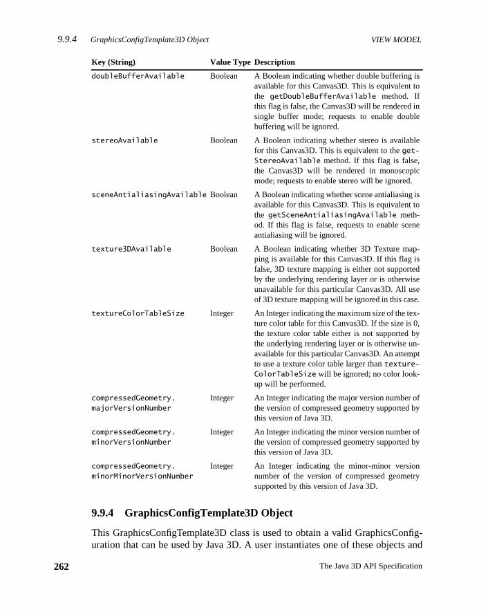
9.9.4 GraphicsConfigTemplate3D Object VIEW MODEL
262
nfig-s and
e
s
e
-
-
fy
fy
y
9.9.4 GraphicsConfigTemplate3D Object
This GraphicsConfigTemplate3D class is used to obtain a valid GraphicsCouration that can be used by Java 3D. A user instantiates one of these object
Key (String) Value Type Description
doubleBufferAvailable Boolean A Boolean indicating whether double buffering isavailable for this Canvas3D. This is equivalent tothe getDoubleBufferAvailable method. Ifthis flag is false, the Canvas3D will be rendered insingle buffer mode; requests to enable doublebuffering will be ignored.
stereoAvailable Boolean A Boolean indicating whether stereo is availablfor this Canvas3D. This is equivalent to theget-StereoAvailable method. If this flag is false,the Canvas3D will be rendered in monoscopicmode; requests to enable stereo will be ignored.
sceneAntialiasingAvailable Boolean A Boolean indicating whether scene antialiasing iavailable for this Canvas3D. This is equivalent tothe getSceneAntialiasingAvailable meth-od. If this flag is false, requests to enable scenantialiasing will be ignored.
texture3DAvailable Boolean A Boolean indicating whether 3D Texture mapping is available for this Canvas3D. If this flag isfalse, 3D texture mapping is either not supportedby the underlying rendering layer or is otherwiseunavailable for this particular Canvas3D. All useof 3D texture mapping will be ignored in this case.
textureColorTableSize Integer An Integer indicating the maximum size of the texture color table for this Canvas3D. If the size is 0,the texture color table either is not supported bythe underlying rendering layer or is otherwise un-available for this particular Canvas3D. An attemptto use a texture color table larger thantexture-ColorTableSize will be ignored; no color look-up will be performed.
compressedGeometry.majorVersionNumber
Integer An Integer indicating the major version number othe version of compressed geometry supported bthis version of Java 3D.
compressedGeometry.minorVersionNumber
Integer An Integer indicating the minor version number othe version of compressed geometry supported bthis version of Java 3D.
compressedGeometry.minorMinorVersionNumber
Integer An Integer indicating the minor-minor versionnumber of the version of compressed geometrsupported by this version of Java 3D.
The Java 3D API Specification
VIEW MODEL GraphicsConfigTemplate3D Object 9.9.4
eds
lues
lues
are
alues
then sets all nondefault attributes as desired. ThegetGraphicsConfiguration
method found in thejava.awt.GraphicsDevice class is then called with thisGraphicsConfigTemplate. A valid GraphicsConfiguration that meets or excewhat was requested in thejava.awt.GraphicsConfigTemplate is returned.
Constructors
public GraphicsConfigTemplate3D()
This constructor constructs a new GraphicsConfigTemplate3D and sets all vato their default:
Methods
public void setDoubleBuffer(int value)public int getDoubleBuffer()
These methods set and retrieve the double-buffering attribute. The valid vaareREQUIRED, PREFERRED, andUNNECESSARY.
public void setStereo(int value)public int getStereo()
These methods set and retrieve the stereo attribute. The valid valuesREQUIRED, PREFERRED, andUNNECESSARY.
public void setSceneAntialiasing(int value)public int getSceneAntialiasing()
These methods set and retrieve the scene antialiasing attribute. The valid vareREQUIRED, PREFERRED, andUNNECESSARY.
Parameter Default Value
doubleBuffer REQUIRED
stereo UNNECESSARY
sceneAntialiasing UNNECESSARY
depthSize 16
redSize 2
greenSize 2
blueSize 2
263Version 1.2, April 2000
9.10 The PhysicalBody Object VIEW MODEL
264
ested
teria
ura-ethodacescre-
thespec-
nter-Thead-
public void setDepthSize(int value)public int getDepthSize()
These methods set and retrieve the depth buffer size requirement.
public void setRedSize(int value)public int getRedSize()public void setGreenSize(int value)public int getGreenSize()public void setBlueSize(int value)public int getBlueSize()
These methods set and retrieve the number of red, green, and blue bits requby this template.
public java.awt.GraphicsConfiguration getBestConfiguration(java.awt.GraphicsConfiguration[] gc)
This method returns the “best” possible configuration that passes the cridefined in the GraphicsConfigTemplate3D.
public boolean isGraphicsConfigSupported(java.awt.GraphicsConfiguration gc)
This method returns a boolean indicating whether the given GraphicsConfigtion can be used to create a drawing surface that can be rendered to. This mreturns true if this GraphicsConfiguration object can be used to create surfthat can be rendered to, false if the GraphicsConfiguration cannot be used toate a drawing surface usable by this API.
9.10 The PhysicalBody Object
Java 3D defines a PhysicalBody object that contains information concerningend user’s physical characteristics. The head parameters allow end users toify their own head’s characteristics, such as the location of the eyes and the ipupilary distance. See Section C.8, “The PhysicalBody Object,” for details.default values are sufficient for applications that are running in a non-hetracked environment and do not manually set the eyepoint.
Constructors
public PhysicalBody()
This constructor constructs and initializes a default PhysicalBody object.
The Java 3D API Specification

VIEW MODEL The PhysicalEnvironment Object 9.11
ed inienton-
9.11 The PhysicalEnvironment Object
The PhysicalEnvironment object defines several methods that are describSection C.9, “The PhysicalEnvironment Object.” The default values are sufficfor applications that do not use continuous input devices that are run in a nhead-tracked display environment.
Constructors
public PhysicalEnvironment()
Constructs and initializes a default PhysicalEnvironment object.
265Version 1.2, April 2000

Version 1.2, April 2000
C H A P T E R 10
sey-pick
ode’sa 3Dcom-
. Forivelyate.and
: an
iory its
ed-
t’s
teial-
vir-
Behaviors and Interpolator
BEHAVIOR nodes provide the means for animating objects, processing kboard and mouse inputs, reacting to movement, and enabling and processingevents. Behavior nodes contain Java code and state variables. A Behavior nJava code can interact with Java objects, change node values within a Javscene graph, change the behavior’s internal state—in general, perform anyputation it wishes.
Simple behaviors can add surprisingly interesting effects to a scene graphexample, one can animate a rigid object by using a Behavior node to repetitmodify the TransformGroup node that points to the object one wishes to animAlternatively, a Behavior node can track the current position of a mousemodify portions of the scene graph in response.
10.1 Behavior Object
A Behavior leaf node object contains a scheduling region and two methodsinitialize method called once when the behavior becomes “live” and apro-
cessStimulus method called whenever appropriate by the Java 3D behavscheduler. The Behavior object also contains the state information needed binitialize andprocessStimulus methods.
The scheduling regiondefines a spatial volume that serves to enable the schuling of Behavior nodes. A Behavior node isactive (can receive stimuli) when-ever a ViewPlatform’s activation volume intersects a Behavior objecscheduling region. Only active behaviors can receive stimuli.
The initialize method allows a Behavior object to initialize its internal staand specify its initial wakeup condition(s). Java 3D invokes a behavior’s initize code when the behavior’s containing BranchGroup node is added to thetual universe. Java 3D does not invoke theinitialize method in a new thread.
267
10.1.1 Code Structure BEHAVIORS AND INTERPOLATORS
268
else
es-
iorfied.lyD toally
, itba-canilitiesstrict
cenero-eatess to
waysasic
mer-
ion.
dul-
Thus, for Java 3D to regain control, theinitialize method must not execute aninfinite loop: It must return. Furthermore, a wakeup condition must be set orthe behavior’sprocessStimulus method is never executed.
TheprocessStimulus method receives and processes a behavior’s ongoing msages. The Java 3D behavior scheduler invokes a Behavior node’sprocessStim-
ulus method when a ViewPlatform’s activation volume intersects a Behavobject’s scheduling region and all of that behavior’s wakeup criteria are satisThe processStimulus method performs its computations and actions (possibincluding the registration of state change information that could cause Java 3wake other Behavior objects), establishes its next wakeup condition, and finexits.
10.1.1 Code Structure
When the Java 3D behavior scheduler invokes a Behavior object’sprocessStim-
ulus method, that method may perform any computation it wishes. Usuallywill change its internal state and specify its new wakeup conditions. Most probly, it will manipulate scene graph elements. However, the behavior codechange only those aspects of a scene graph element permitted by the capabassociated with that scene graph element. A scene graph’s capabilities rebehavioral manipulation to those manipulations explicitly allowed.
The application must provide the Behavior object with references to those sgraph elements that the Behavior object will manipulate. The application pvides those references as arguments to the behavior’s constructor when it crthe Behavior object. Alternatively, the Behavior object itself can obtain accesthe relevant scene graph elements either when Java 3D invokes itsinitialize
method or each time Java 3D invokes itsprocessStimulus method.
Behavior methods have a very rigid structure. Java 3D assumes that they alrun to completion (if needed, they can spawn threads). Each method’s bstructure consists of the following:
• Code to decode and extract references from the WakeupCondition enuation that caused the object’s awakening.
• Code to perform the manipulations associated with the WakeupCondit
• Code to establish this behavior’s new WakeupCondition.
• A path to Exit (so that execution returns to the Java 3D behavior scheer).
The Java 3D API Specification
BEHAVIORS AND INTERPOLATORS WakeupCriterion Object10.1.3
rentple
ndi-aviorenu-
e inuse
bject
bject
any
iateusu-Thus,
10.1.2 WakeupCondition Object
A WakeupCondition object is an abstract class specialized to fourteen diffeWakeupCriterion objects and to four combining objects containing multiWakeupCriterion objects.
A Behavior node provides the Java 3D behavior scheduler with a WakeupCotion object. When that object’s WakeupCondition has been satisfied, the behscheduler hands that same WakeupCondition back to the Behavior via anmeration.
10.1.3 WakeupCriterion Object
Java 3D provides a rich set of wakeup criteria that Behavior objects can usspecifying a complex WakeupCondition. These wakeup criteria can caJava 3D’s behavior scheduler to invoke a behavior’sprocessStimulus methodwhenever
• The center of a ViewPlatform enters a specified region.
• The center of a ViewPlatform exits a specified region.
• A behavior is activated.
• A behavior is deactivated.
• A specified TransformGroup node’s transform changes.
• Collision is detected between a specified Shape3D node’s Geometry oand any other object.
• Movement occurs between a specified Shape3D node’s Geometry oand any other object with which it collides.
• A specified Shape3D node’s Geometry object no longer collides withother object.
• A specified Behavior object posts a specific event.
• A specified AWT event occurs.
• A specified time interval elapses.
• A specified number of frames have been drawn.
• The center of a specified Sensor enters a specified region.
• The center of a specified Sensor exits a specified region.
A Behavior object constructs a WakeupCriterion by constructing the approprcriterion object. The Behavior object must provide the appropriate arguments (ally a reference to some scene graph object and possibly a region of interest).
269Version 1.2, April 2000
10.1.4 Composing WakeupCriterion Objects BEHAVIORS AND INTERPOLATORS
270
ion
oreosite
at
ts
bys as
mentsific
heirdoord the
rces0 orcon-ated
to specify a WakeupOnViewPlatformEntry, a behavior would specify the regthat will cause the behavior to execute if a ViewPlatform enters it.
10.1.4 Composing WakeupCriterion Objects
A Behavior object can combine multiple WakeupCriterion objects into a mpowerful, composite WakeupCondition. Java 3D behaviors construct a compWakeupCondition in one of the following ways:
• WakeupAnd: An array of WakeupCriterion objects ANDed together.
WakeupCriterion && WakeupCriterion && ...
• WakeupOr: An array of WakeupCriterion objects ORed together.
WakeupCriterion || WakeupCriterion || ...
• WakeupAndOfOrs: An array of WakeupOr WakeupCondition objects thare then ANDed together.
WakeupOr && WakeupOr && ...
• WakeupOrOfAnds: An array of WakeupAnd WakeupCondition objecthat are then ORed together.
WakeupAnd || WakeupAnd || ...
10.2 Composing Behaviors
Behavior objects can condition themselves to awaken only when signaledanother Behavior node. The WakeupOnBehaviorPost WakeupCriterion takearguments a reference to a Behavior node and an integer. These two arguallow a behavior to limit its wakeup criterion to a specific post by a specbehavior.
The WakeupOnBehaviorPost WakeupCriterion permits behaviors to chain tcomputations, allowing parenthetical computations—one behavior opens aand the second closes the same door, or one behavior highlights an object ansecond unhighlights the same object.
10.3 Scheduling
As a virtual universe grows large, Java 3D must carefully husband its resouto ensure adequate performance. In a 10,000-object virtual universe with 40so Behavior nodes, a naive implementation of Java 3D could easily end upsuming the majority of its compute cycles in executing the behaviors associ
The Java 3D API Specification
BEHAVIORS AND INTERPOLATORS How Java 3D Performs Execution Culling10.4
the
uni-000-ouldsso-few
igh-nly
pro-lec-tely
con-g allmainrform
rming
aeup
he
ift
with the 400 Behavior objects before it draws a frame. In such a situation,frame rate could easily drop to unacceptable levels.
Behavior objects are usually associated with geometric objects in the virtualverse. In our example of 400 Behavior objects scattered throughout a 10,object virtual universe, only a few of these associated geometric objects wbe visible at a given time. A sizable fraction of the Behavior nodes—those aciated with nonvisible objects—need not be executed. Only those relativelyBehavior objects that are associated with visible objects must be executed.
Java 3D mitigates the problem of a large number of Behavior nodes in a hpopulation virtual universe through execution culling—choosing to invoke othose behaviors that have high relevance.
Java 3D requires each behavior to have ascheduling regionand to post a wakeupcondition. Together a behavior’s scheduling region and wakeup conditionvide Java 3D’s behavior scheduler with sufficient domain knowledge to setively prune behavior invocations and invoke only those behaviors that absoluneed to be executed.
10.4 How Java 3D Performs Execution Culling
Java 3D finds all scheduling regions associated with Behavior nodes andstructs a scheduling/volume tree. It also creates an AND/OR tree containinthe Behavior node wakeup criteria. These two data structures provide the doknowledge Java 3D needs to prune unneeded behavior execution (to pe“execution triage”).
Java 3D must track a behavior’s wakeup conditions only if a ViewPlatfoobject’s activation volume intersects with that Behavior object’s schedulregion. If the ViewPlatform object’s activation volume does not intersect withbehavior’s scheduling region, Java 3D can safely ignore that behavior’s wakcriteria.
In essence, the Java 3D scheduler performs the following checks:
• Find all Behavior objects with scheduling regions that intersect tViewPlatform object’s activation volume.
• For each Behavior object within the ViewPlatform’s activation volume,that behavior’s WakeupCondition istrue, schedule that Behavior objecfor execution.
271Version 1.2, April 2000
10.5 The Behavior API BEHAVIORS AND INTERPOLATORS
272
been
thethe
r all
thethat
dulerend
Java 3D’s behavior scheduler executes those Behavior objects that havescheduled by calling the behavior’sprocessStimulus method.
10.5 The Behavior API
The Java 3D behavior API spreads its functionality across three objects:Behavior leaf node, the WakeupCondition object and its subclasses, andWakeupCriterion objects.
10.5.1 The Behavior Node
The Behavior object is an abstract class that contains the framework fobehavioral components in Java 3D.
Constructor
The Behavior leaf node class defines the following constructor:
public Behavior()
Constructs a Behavior node with default parameters:
Methods
The Behavior leaf node class defines the following methods:
public abstract void initialize()
This method, invoked by Java 3D’s behavior scheduler, is used to initializebehavior’s state variables and to establish its WakeupConditions. Classesextend Behavior must provide their owninitialize method. Applicationsshouldnot call this method.
public abstract void processStimulus(Enumeration criteria)
This method processes stimuli destined for this behavior. The behavior scheinvokes this method if its WakeupCondition is satisfied. Classes that ext
Parameter Default Value
enable flag true
schedulingBounds null
schedulingBoundingLeafnull
The Java 3D API Specification
BEHAVIORS AND INTERPOLATORS The Behavior Node10.5.1
nds.leaf
onend
ding-
lled
f theave
hodonthery”is
ori-me
Behavior must provide their ownprocessStimulus method. Applications shouldnot call this method.
public void setSchedulingBounds(Bounds region)public Bounds getSchedulingBounds()
These two methods access or modify the Behavior node’s scheduling bouThis bounds is used as the scheduling region when the scheduling boundingis set tonull. A behavior is scheduled for activation when its scheduling regiintersects the ViewPlatform’s activation volume (if its wakeup criteria have besatisfied). ThegetSchedulingBounds method returns a copy of the associatebounds.
public void setSchedulingBoundingLeaf(BoundingLeaf region)public BoundingLeaf getSchedulingBoundingLeaf()
These two methods access or modify the Behavior node’s scheduling bounleaf. When set to a value other thannull, this bounding leaf overrides the scheduling bounds object and is used as the scheduling region.
protected void wakeupOn(WakeupCondition criteria)
This method defines this behavior’s wakeup criteria. This method may be caonly from a Behavior object’sinitialize or processStimulus methods to(re)arm the next wakeup. It should be the last thing done by those methods.
public void postId(int postId)
This method, when invoked by a behavior, informs the Java 3D scheduler oidentified event. The scheduler will schedule other Behavior objects that hregistered interest in this posting.
protected View getView()
This method returns the primary view associated with this behavior. This metis useful with certain types of behaviors, such as Billboard and LOD, that relyper-View information and with behaviors in general in regards to scheduling (distance from the view platform determines the active behaviors). The “primaview is defined to be the first View attached to a live ViewPlatform, if theremore than one active View. So, for instance, Billboard behaviors would beented toward this primary view, in the case of multiple active views into the sascene graph.
273Version 1.2, April 2000
10.5.2 WakeupCondition Object BEHAVIORS AND INTERPOLATORS
274
rion,. Aand.
nu-
pCon-tiallytion.those
Eachiateded ahat
vior
10.5.2 WakeupCondition Object
WakeupCondition is an abstract class that is extended by the WakeupCriteWakeupOr, WakeupAnd, WakeupOrOfAnds, and WakeupAndOfOr classesBehavior node hands a WakeupCondition object to the behavior scheduler,the behavior scheduler hands back an enumeration of that WakeupCondition
Methods
The Java 3D API provides two methods for constructing WakeupCondition emerations:
public Enumeration allElements()public Enumeration triggeredElements()
These two methods create enumerators that sequentially access this Wakeudition’s wakeup criteria. The first method creates an enumerator that sequenpresents all wakeup criteria that were used to construct this WakeupCondiThe second method creates an enumerator that sequentially presents onlywakeup criteria that have been satisfied.
10.5.3 The WakeupCriterion Objects
WakeupCriterion is an abstract class that consists of several subclasses.subclass specifies one particular wakeup criterion, that criterion’s assocarguments (if any), and either a flag that indicates whether this criterion causBehavior object to awaken or a return field containing the information tcaused the Behavior object to awaken.
Methods
public boolean hasTriggered()
This predicate method returnstrue if this WakeupCriterion contributed to wak-ing a Behavior object.
10.5.3.1 WakeupOnAWTEvent
This WakeupCriterion object specifies that Java 3D should awaken a behawhen the specified AWT event occurs.
The Java 3D API Specification
BEHAVIORS AND INTERPOLATORS The WakeupCriterion Objects10.5.3
WTe-e
thiscan
theon.ted.
vior
hav-
Constructors
public WakeupOnAWTEvent(int AWTId)public WakeupOnAWTEvent(long eventMask)
The first constructor creates a WakeupOnAWTEvent object thatinforms theJava 3D scheduler to wake up the specified Behavior object whenever the Aevent specified byAWTId occurs. The second constructor creates a WakupOnAWTEvent object thatinforms the Java 3D scheduler to wake up thspecified Behavior object whenever any of the specified AWTEVENT_MASK
events occur. TheeventMask consists of an ORed collection ofEVENT_MASK val-ues.
Methods
public AWTEvent[] getAWTEvent()
This method returns the array of consecutive AWT events that triggeredWakeupCriterion to awaken the Behavior object. The Behavior objectretrieve theAWTEvent array and process it in any way it wishes.
10.5.3.2 WakeupOnActivation
The WakeupOnActivation object specifies a wakeup the first timeViewPlatform’s activation region intersects with this object’s scheduling regiThis gives the behavior an explicit means of executing code when it is activa
Constructors
public WakeupOnActivation()
This constructor creates a WakeupOnActivation criterion.
10.5.3.3 WakeupOnBehaviorPost
This WakeupCriterion object specifies that Java 3D should awaken this behawhen the specified behavior posts the specified ID.
Constructors
public WakeupOnBehaviorPost(Behavior behavior, int postId)
This constructor creates a WakeupOnBehaviorPost object thatinforms theJava 3D scheduler to wake up this Behavior object whenever the specified beior posts the specifiedpostId. A postId of 0 specifies that this behavior should
275Version 1.2, April 2000
10.5.3 The WakeupCriterion Objects BEHAVIORS AND INTERPOLATORS
276
peci-
ostidwill
hav-the
of ad-n it
viorthatn bepsed-
awaken on any post from the specified behavior. Specifying anull behaviorimplies that this behavior should awaken whenever any behavior posts the sfied postId.
Methods
public int getPostId()
This method returns thepostId used in creating this WakeupCriterion.
public Behavior getBehavior()
This method returns the behavior specified in this object’s constructor.
public int getTriggeringPostId()
This method returns the postid that caused the behavior to wake up. If the pused to construct this wakeup criterion was not zero, the triggering postidalways be equal to the postid used in the constructor.
public Behavior getTriggeringBehavior()
This method returns the behavior that triggered this wakeup. If the arming beior used to construct this object was not null, the triggering behavior will besame as the arming behavior.
10.5.3.4 WakeupOnDeactivation
The WakeupOnDeactivation object specifies a wakeup on the first detectionViewPlatform’s activation region no longer intersecting with this object’s scheuling region. This gives the behavior an explicit means of executing code wheis deactivated.
Constructors
public WakeupOnDeactivation()
This constructor creates a new WakeupOnDeactivation criterion.
10.5.3.5 WakeupOnElapsedFrames
This WakeupCriterion object specifies that Java 3D should awaken this behaafter it has rendered the specified number of frames. A value of 0 impliesJava 3D will awaken this behavior at the next frame. The wakeup criterion caeither passive or nonpassive. If a behavior uses a nonpassive WakeupOnElaFrames, the rendering system will run continuously.
The Java 3D API Specification
BEHAVIORS AND INTERPOLATORS The WakeupCriterion Objects10.5.3
ter it
theen
this
truct-
vior
ified
berually
ew in 1.2
ew in 1.2
Constructors
public WakeupOnElapsedFrames(int frameCount)
This constructor creates a nonpassive WakeupOnElapsedFrames object thainforms the Java 3D scheduler to wake up the specified Behavior object afthas drawnframeCount frames. AframeCount value ofN means wake up at theend of frameN, where the current frame is 0. AframeCount value of 0 meanswake up at the end of the current frame.
public WakeupOnElapsedFrames(int frameCount, boolean passive)
This constructor creates a WakeupOnElapsedFrames criterion. Thepassive flagindicates whether this behavior is passive. A nonpassive behavior will causerendering system to run continuously. A passive behavior will run only whsome other event causes a frame to be run.
Methods
public int getElapsedFrameCount()
This method returns the frame count that was specified when constructingobject.
public boolean isPassive()
This method retrieves the state of the passive flag that was used when consing this object.
10.5.3.6 WakeupOnElapsedTime
This WakeupCriterion object specifies that Java 3D should awaken this behaafter an elapsed number of milliseconds.
Constructors
public WakeupOnElapsedTime(long milliseconds)
This constructor creates a WakeupOnElapsedTime object thatinforms theJava 3D scheduler to wake up the specified Behavior object after the specnumber of milliseconds.
Note: The Java 3D scheduler will schedule the object after the specified numof milliseconds have elapsed, not before. However, the elapsed time may actbe slightly greater than the time specified.
N
N
277Version 1.2, April 2000
10.5.3 The WakeupCriterion Objects BEHAVIORS AND INTERPOLATORS
278
s.
vior
t an
cts a
n.
viorion.
rre-
New in 1.2
Methods
public long getElapsedFrameTime()
This method returns the WakeupCriterion’s elapsed time value in millisecond
10.5.3.7 WakeupOnSensorEntry
This WakeupCriterion object specifies that Java 3D should awaken this behawhen any sensor enters the specified region.
Note: There can be situations in which a sensor may enter and then exiarmed region so rapidly that neither the Entry nor Exit condition is engaged.
Constructors
public WakeupOnSensorEntry(Bounds region)
This constructor creates a WakeupOnSensorEntry object thatinforms theJava 3D scheduler to wake up the specified Behavior object whenever it detesensor within the specifiedregion for the first time.
Methods
public Bounds getBounds()
This method returns the Bounds object used in creating this WakeupCriterio
public Sensor getTriggeringSensor()
This method retrieves he Sensor object that caused the wakeup.
10.5.3.8 WakeupOnSensorExit
This WakeupCriterion object specifies that Java 3D should awaken this behawhen any sensor, already marked as within the region, is no longer in that reg
Note: This semantic guarantees that an Exit condition is engaged if its cosponding Entry condition was engaged.
The Java 3D API Specification
BEHAVIORS AND INTERPOLATORS The WakeupCriterion Objects10.5.3
e it
n.
ake-her
orphs are
ifiedny
ew in 1.2
Constructors
public WakeupOnSensorExit(Bounds region)
This constructor creates a WakeupOnSensorExit object thatinforms theJava 3D scheduler to wake up the specified Behavior object the first timdetects that a sensor has left the specifiedregion.
Methods
public Bounds getBounds()
This method returns the Bounds object used in creating this WakeupCriterio
public Sensor getTriggeringSensor()
This method retrieves the Sensor object that caused the wakeup.
10.5.3.9 WakeupOnCollisionEntry
This WakeupCriterion object specifies that Java 3D should awaken the WupOnCollisionEntry behavior when the specified object collides with any otobject in the scene graph.
Constants
public static final int USE_GEOMETRYpublic static final int USE_BOUNDS
These constants specify whether collision against a Group, Shape, or Mnode is done using the actual geometry or whether the geometric boundused as an approximation.
Constructors
public WakeupOnCollisionEntry(SceneGraphPath armingPath)public WakeupOnCollisionEntry(SceneGraphPath armingPath, int speedHint)public WakeupOnCollisionEntry(Node armingNode)public WakeupOnCollisionEntry(Node armingNode, int speedHint)public WakeupOnCollisionEntry(Bounds armingBounds)
These constructors create a WakeupOnCollisionEntry object thatinforms theJava 3D scheduler to wake up the specified Behavior object if the spec“armed” node’s geometry or the specified “armed” bounds collides with a
N
279Version 1.2, April 2000
10.5.3 The WakeupCriterion Objects BEHAVIORS AND INTERPOLATORS
280
ying
ake-ith
orphs are
ifiedes
other object in the scene graph. ThespeedHint flag is eitherUSE_GEOMETRY orUSE_BOUNDS.
Methods
public SceneGraphPath getArmingPath()public Bounds getArmingBounds()
These methods return the “collidable” path or bounds object used in specifthe collision detection.
public SceneGraphPath getTriggeringPath()public Bounds getTriggeringBounds()
These methods return the path or bounds object that caused the collision.
10.5.3.10 WakeupOnCollisionExit
This WakeupCriterion object specifies that Java 3D should awaken the WupOnCollisionExit behavior when the specified object no longer collides wany other object in the scene graph.
Constants
public static final int USE_GEOMETRYpublic static final int USE_BOUNDS
These constants specify whether collision against a Group, Shape, or Mnode is done using the actual geometry or whether the geometric boundused as an approximation.
Constructors
public WakeupOnCollisionExit(SceneGraphPath armingPath)public WakeupOnCollisionExit(SceneGraphPath armingPath, int speedHint)public WakeupOnCollisionExit(Node armingNode)public WakeupOnCollisionExit(Node armingNode, int speedHint)public WakeupOnCollisionExit(Bounds armingBounds)
These constructors create a WakeupOnCollisionExit object thatinforms theJava 3D scheduler to wake up the specified Behavior object if the spec“armed” node’s geometry or the specified “armed” bounds no longer collidwith any other object in the scene graph. ThespeedHint flag is eitherUSE_GEOMETRY or USE_BOUNDS.
The Java 3D API Specification

BEHAVIORS AND INTERPOLATORS The WakeupCriterion Objects10.5.3
ying
ake-n a
orphs are
ifiedthe
Methods
public SceneGraphPath getArmingPath()public Bounds getArmingBounds()
These methods return the “collidable” path or bounds object used in specifthe collision detection.
public SceneGraphPath getTriggeringPath()public Bounds getTriggeringBounds()
These methods return the path or bounds object that caused the collision.
10.5.3.11 WakeupOnCollisionMovement
This WakeupCriterion object specifies that Java 3D should awaken the WupOnCollisionMovement behavior when the specified object moves while istate of collision with any other object in the scene graph.
Constants
public static final int USE_GEOMETRYpublic static final int USE_BOUNDS
These constants specify whether collision against a Group, Shape, or Mnode is done using the actual geometry or whether the geometric boundused as an approximation.
Constructors
public WakeupOnCollisionMovement(SceneGraphPath armingPath)public WakeupOnCollisionMovement(SceneGraphPath armingPath, int speedHint)public WakeupOnCollisionMovement(Node armingNode)public WakeupOnCollisionMovement(Node armingNode, int speedHint)public WakeupOnCollisionMovement(Bounds armingBounds)
These constructors create a WakeupOnCollisionMovement object thatinformsthe Java 3D scheduler to wake up the specified Behavior object if the specnode’s geometry or the specified bounds collides with any other object inscene graph. ThespeedHint flag is eitherUSE_GEOMETRY or USE_BOUNDS.
281Version 1.2, April 2000
10.5.3 The WakeupCriterion Objects BEHAVIORS AND INTERPOLATORS
282
ying
ake-ed
exited.
er it
n.
ake-as
rre-
Methods
public SceneGraphPath getArmingPath()public Bounds getArmingBounds()
These methods return the “collidable” path or bounds object used in specifthe collision detection.
public SceneGraphPath getTriggeringPath()public Bounds getTriggeringBounds()
These methods return the path or bounds object that caused the collision.
10.5.3.12 WakeupOnViewPlatformEntry
This WakeupCriterion object specifies that Java 3D should awaken the WupOnViewPlatformEntry behavior when any ViewPlatform enters the specifiregion.
Note: There can be situations in which a ViewPlatform may enter and thenan armed region so rapidly that neither the Entry nor Exit condition is engag
Constructors
public WakeupOnViewPlatformEntry(Bounds region)
This constructor creates a WakeupOnViewPlatformEntry object thatinformsthe Java 3D scheduler to wake up the specified Behavior object whenevdetects a ViewPlatform center within the specifiedregion for the first time.
Methods
public Bounds getBounds()
This method returns the Bounds object used in creating this WakeupCriterio
10.5.3.13 WakeupOnViewPlatformExit
This WakeupCriterion object specifies that Java 3D should awaken the WupOnViewPlatformExit behavior when any ViewPlatform, already markedwithin the region, is no longer in that region.
Note: This semantic guarantees that an Exit condition gets engaged if its cosponding Entry condition was engaged.
The Java 3D API Specification
BEHAVIORS AND INTERPOLATORS The WakeupCriterion Objects10.5.3
e it
n.
form
Cri-
edthis
me
the
Constructors
public WakeupOnViewPlatformExit(Bounds region)
This constructor creates a WakeupOnViewPlatformExit object thatinforms theJava 3D scheduler to wake up the specified Behavior object the first timdetects that a ViewPlatform has left the specifiedregion.
Methods
public Bounds getBounds()
This method returns the Bounds object used in creating this WakeupCriterio
10.5.3.14 WakeupOnTransformChange
The WakeupOnTransformChange object specifies a wakeup when the transwithin a specified TransformGroup changes.
Constructors
public WakeupOnTransformChange(TransformGroup node)
This constructor creates a new WakeupOnTransformChange criterion.
Methods
public TransformGroup getTransformGroup()
This method returns the TransformGroup node used in creating this Wakeupterion.
10.5.3.15 WakeupAnd
The WakeupAnd class specifies any number of wakeup conditions ANDtogether. This WakeupCondition object specifies that Java 3D should awakenBehavior when all of the WakeupCondition’s constituent wakeup criteria becovalid.
Constructors
public WakeupAnd(WakeupCriterion conditions[])
This constructor creates a WakeupAnd object thatinforms the Java 3D sched-uler to wake up this Behavior object when all the conditions specified inarray of WakeupCriterion objects have become valid.
283Version 1.2, April 2000
10.5.3 The WakeupCriterion Objects BEHAVIORS AND INTERPOLATORS
284
ther.hav-es
rof
ionsuld
pOr
ons
onsouldeup
ndi-
10.5.3.16 WakeupOr
The WakeupOr class specifies any number of wakeup conditions ORed togeThis WakeupCondition object specifies that Java 3D should awaken this Beior when any of the WakeupCondition’s constituent wakeup criteria becomvalid.
Constructors
public WakeupOr(WakeupCriterion conditions[])
This constructor creates a WakeupOr object thatinforms the Java 3D scheduleto wake up this Behavior object when any condition specified in the arrayWakeupCriterion objects becomes valid.
10.5.3.17 WakeupAndOfOrs
The WakeupAndOfOrs class specifies any number of OR wakeup conditANDed together. This WakeupCondition object specifies that Java 3D shoawaken this Behavior when all of the WakeupCondition’s constituent Wakeuconditions become valid.
Constructors
public WakeupAndOfOrs(WakeupOr conditions[])
This constructor creates a WakeupAndOfOrs object thatinforms the Java 3Dscheduler to wake up this Behavior object when all of the WakeupOr conditispecified in the array of WakeupOr objects become valid.
10.5.3.18 WakeupOrOfAnds
The WakeupOrOfAnds class specifies any number of AND wakeup conditiORed together. This WakeupCondition object specifies that Java 3D shawaken this Behavior when any of the WakeupCondition’s constituent WakAnd conditions becomes valid.
Constructors
public WakeupOrOfAnds(WakeupAnd conditions[])
This constructor creates a WakeupOrOfAnds object thatinforms the Java 3Dscheduler to wake up this Behavior object when any of the WakeupAnd cotions specified in the array of WakeupAnd objects becomes valid.
The Java 3D API Specification
BEHAVIORS AND INTERPOLATORS Mapping Time to Alpha10.6.1
aremeioral
ingde,
ecify-torsd a
gethee of, anlpha
the
ap-rent
givenicatentsistent
ing.rticale to
orme,ange.
10.6 Interpolator Behaviors
This section describes Java 3D’s predefined Interpolator behaviors. Theycalled interpolatorsbecause they smoothly interpolate between the two extrevalues that an interpolator can produce. Interpolators perform simple behavacts, yet they provide broad functionality.
The Java 3D API provides interpolators for a number of functions: manipulattransforms within a TransformGroup, modifying the values of a Switch noand modifying Material attributes such as color and transparency.
These predefined Interpolator behaviors share the same mechanism for sping and later for converting a temporal value into an alpha value. Interpolaconsist of two portions: a generic portion that all interpolators share andomain-specific portion.
The generic portion maps time in milliseconds onto a value in the ran[0.0, 1.0] inclusive. The domain-specific portion maps an alpha value inrange [0.0, 1.0] onto a value appropriate to the predefined behavior’s rangoutputs. An alpha value of 0.0 generates an interpolator’s minimum valuealpha value of 1.0 generates an interpolator’s maximum value, and an avalue somewhere in between generates a value proportionally in betweenminimum and maximum values.
10.6.1 Mapping Time to Alpha
Several parameters control the mapping of time onto an alpha value. That mping is deterministic as long as its parameters do not change. Thus, two diffeinterpolators with the same parameters will generate the same alpha valuethe same time value. This means that two interpolators that do not communcan still precisely coordinate their activities, even if they reside in differethreads or even different processors—as long as those processors have conclocks.
Figure 10-1 shows the components of an interpolator’s time-to-alpha mappTime is represented on the horizontal axis. Alpha is represented on the veaxis. As we move from left to right, we see the alpha value start at 0.0, ris1.0, and then decline back to 0.0 on the right-hand side.
On the left-hand side, the trigger time defines when this interpolator’s wavefbegins in milliseconds. The region directly to the right of the trigger timlabeled Phase Delay, defines a time period where the waveform does not ch
285Version 1.2, April 2000
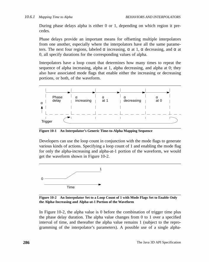
10.6.1 Mapping Time to Alpha BEHAVIORS AND INTERPOLATORS
286
pre-
torsame-
t the; theyasing
rateflaguld
luscifiedpro-ha-
During phase delays alpha is either 0 or 1, depending on which region itcedes.
Phase delays provide an important means for offsetting multiple interpolafrom one another, especially where the interpolators have all the same parters. The next four regions, labeledα increasing,α at 1, α decreasing, andα at0, all specify durations for the corresponding values of alpha.
Interpolators have a loop count that determines how many times to repeasequence of alpha increasing, alpha at 1, alpha decreasing, and alpha at 0also have associated mode flags that enable either the increasing or decreportions, or both, of the waveform.
Figure 10-1 An Interpolator’s Generic Time-to-Alpha Mapping Sequence
Developers can use the loop count in conjunction with the mode flags to genevarious kinds of actions. Specifying a loop count of 1 and enabling the modefor only the alpha-increasing and alpha-at-1 portion of the waveform, we woget the waveform shown in Figure 10-2.
Figure 10-2 An Interpolator Set to a Loop Count of 1 with Mode Flags Set to Enable Onlythe Alpha-Increasing and Alpha-at-1 Portion of the Waveform
In Figure 10-2, the alpha value is 0 before the combination of trigger time pthe phase delay duration. The alpha value changes from 0 to 1 over a speinterval of time, and thereafter the alpha value remains 1 (subject to the regramming of the interpolator’s parameters). A possible use of a single alp
Phasedelay
αat 1
αincreasing
αdecreasing
αat 0
Trigger
α
Time
0
1
The Java 3D API Specification
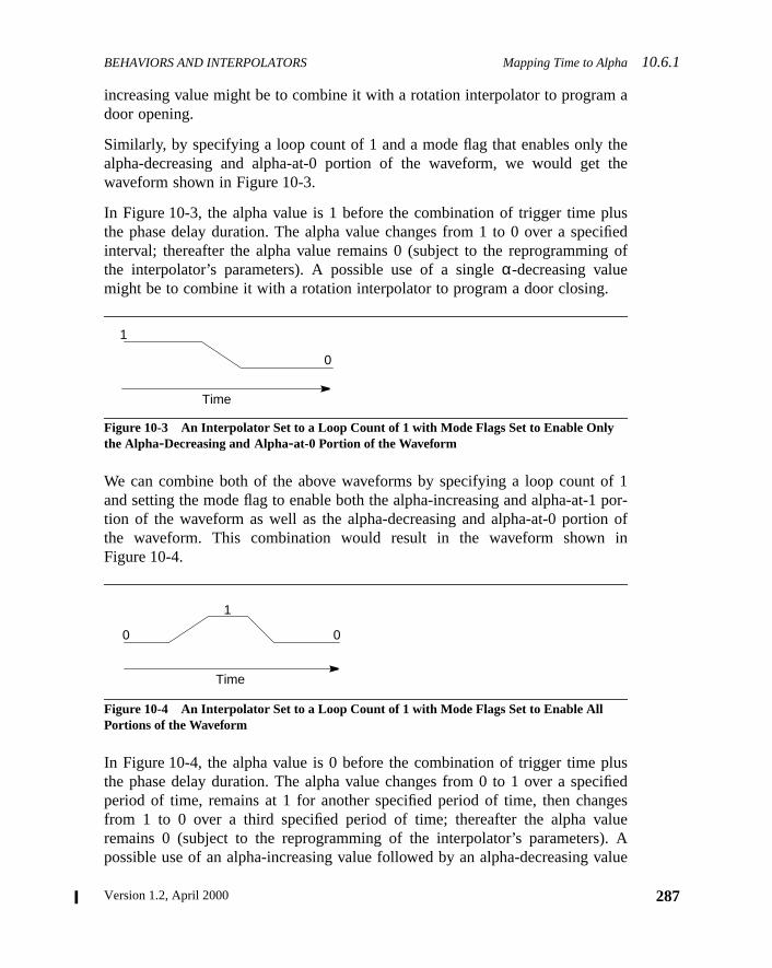
BEHAVIORS AND INTERPOLATORS Mapping Time to Alpha10.6.1
a
thethe
luscifiedg of
f 1por-
n ofin
luscifiedgeslue). Avalue
increasing value might be to combine it with a rotation interpolator to programdoor opening.
Similarly, by specifying a loop count of 1 and a mode flag that enables onlyalpha-decreasing and alpha-at-0 portion of the waveform, we would getwaveform shown in Figure 10-3.
In Figure 10-3, the alpha value is 1 before the combination of trigger time pthe phase delay duration. The alpha value changes from 1 to 0 over a speinterval; thereafter the alpha value remains 0 (subject to the reprogramminthe interpolator’s parameters). A possible use of a singleα-decreasing valuemight be to combine it with a rotation interpolator to program a door closing.
Figure 10-3 An Interpolator Set to a Loop Count of 1 with Mode Flags Set to Enable Onlythe Alpha-Decreasing and Alpha-at-0 Portion of the Waveform
We can combine both of the above waveforms by specifying a loop count oand setting the mode flag to enable both the alpha-increasing and alpha-at-1tion of the waveform as well as the alpha-decreasing and alpha-at-0 portiothe waveform. This combination would result in the waveform shownFigure 10-4.
Figure 10-4 An Interpolator Set to a Loop Count of 1 with Mode Flags Set to Enable AllPortions of the Waveform
In Figure 10-4, the alpha value is 0 before the combination of trigger time pthe phase delay duration. The alpha value changes from 0 to 1 over a speperiod of time, remains at 1 for another specified period of time, then chanfrom 1 to 0 over a third specified period of time; thereafter the alpha varemains 0 (subject to the reprogramming of the interpolator’s parameterspossible use of an alpha-increasing value followed by an alpha-decreasing
Time
1
0
Time
0
1
0
287Version 1.2, April 2000
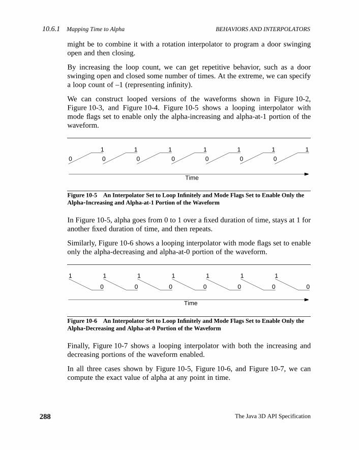
10.6.1 Mapping Time to Alpha BEHAVIORS AND INTERPOLATORS
288
ng
doorecify
0-2,ithf the
for
ble
nd
can
might be to combine it with a rotation interpolator to program a door swingiopen and then closing.
By increasing the loop count, we can get repetitive behavior, such as aswinging open and closed some number of times. At the extreme, we can spa loop count of –1 (representing infinity).
We can construct looped versions of the waveforms shown in Figure 1Figure 10-3, and Figure 10-4. Figure 10-5 shows a looping interpolator wmode flags set to enable only the alpha-increasing and alpha-at-1 portion owaveform.
Figure 10-5 An Interpolator Set to Loop Infinitely and Mode Flags Set to Enable Only theAlpha-Increasing and Alpha-at-1 Portion of the Waveform
In Figure 10-5, alpha goes from 0 to 1 over a fixed duration of time, stays at 1another fixed duration of time, and then repeats.
Similarly, Figure 10-6 shows a looping interpolator with mode flags set to enaonly the alpha-decreasing and alpha-at-0 portion of the waveform.
Figure 10-6 An Interpolator Set to Loop Infinitely and Mode Flags Set to Enable Only theAlpha-Decreasing and Alpha-at-0 Portion of the Waveform
Finally, Figure 10-7 shows a looping interpolator with both the increasing adecreasing portions of the waveform enabled.
In all three cases shown by Figure 10-5, Figure 10-6, and Figure 10-7, wecompute the exact value of alpha at any point in time.
1
0
1
0
1
0
1
0
1
0
1
0
1
0
Time
Time
1
0
1
0
1
0
1
0
1
0
1
0
1
0
The Java 3D API Specification
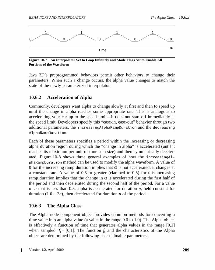
BEHAVIORS AND INTERPOLATORS The Alpha Class10.6.3
theirch the
d upus to
attwo
asingtil iteler-
oft
singfalue
g aject0,1]
Figure 10-7 An Interpolator Set to Loop Infinitely and Mode Flags Set to Enable AllPortions of the Waveform
Java 3D’s preprogrammed behaviors permit other behaviors to changeparameters. When such a change occurs, the alpha value changes to matstate of the newly parameterized interpolator.
10.6.2 Acceleration of Alpha
Commonly, developers want alpha to change slowly at first and then to speeuntil the change in alpha reaches some appropriate rate. This is analogoaccelerating your car up to the speed limit—it does not start off immediatelythe speed limit. Developers specify this “ease-in, ease-out” behavior throughadditional parameters, theincreasingAlphaRampDuration and thedecreasingAlphaRampDuration.
Each of these parameters specifies a period within the increasing or decrealpha duration region during which the “change in alpha” is accelerated (unreaches its maximum per-unit-of-time step size) and then symmetrically decated. Figure 10-8 shows three general examples of how theincreasingAl-
phaRampDuration method can be used to modify the alpha waveform. A value0 for the increasing ramp duration implies thatα is not accelerated; it changes aa constant rate. A value of 0.5 or greater (clamped to 0.5) for this increaramp duration implies that the change inα is accelerated during the first half othe period and then decelerated during the second half of the period. For a vof n that is less than 0.5, alpha is accelerated for durationn, held constant forduration (1.0 – 2n), then decelerated for durationn of the period.
10.6.3 The Alpha Class
The Alpha node component object provides common methods for convertintime value into an alpha value (a value in the range 0.0 to 1.0). The Alpha obis effectively a function of time that generates alpha values in the range [when sampled:ft = [0,1]. The functionft and the characteristics of the Alphaobject are determined by the following user-definable parameters:
1
00
1
0
1
0
1
0
Time
289Version 1.2, April 2000
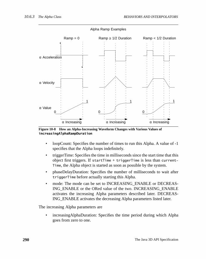
10.6.3 The Alpha Class BEHAVIORS AND INTERPOLATORS
290
-1
this
fter
S-
AS-
ha
Figure 10-8 How an Alpha-Increasing Waveform Changes with Various Values ofincreasingAlphaRampDuration
• loopCount: Specifies the number of times to run this Alpha. A value ofspecifies that the Alpha loops indefinitely.
• triggerTime: Specifies the time in milliseconds since the start time thatobject first triggers. IfstartTime + triggerTime is less thancurrent-Time, the Alpha object is started as soon as possible by the system.
• phaseDelayDuration: Specifies the number of milliseconds to wait atriggerTime before actually starting this Alpha.
• mode: The mode can be set to INCREASING_ENABLE or DECREAING_ENABLE or the ORed value of the two. INCREASING_ENABLEactivates the increasing Alpha parameters described later. DECREING_ENABLE activates the decreasing Alpha parameters listed later.
The increasing Alpha parameters are
• increasingAlphaDuration: Specifies the time period during which Alpgoes from zero to one.
•
•
Alpha Ramp Examples
Ramp = 0 Ramp ≥ 1/2 Duration Ramp < 1/2 Duration
α Acceleration
α Velocity
α Value
α Increasing
0
1
α Increasing
0
1
0
1
α Increasing
The Java 3D API Specification
BEHAVIORS AND INTERPOLATORS The Alpha Class10.6.3
ich
ac-in-mp.n-p).
e.
ha
ich
tionhepa-
the
ro.
asing
• increasingAlphaRampDuration: Specifies the time period during whthe Alpha step size increases at the beginning of theincreasingAlphaDu-
ration and, correspondingly, decreases at the end of theincreasingAl-
phaDuration. This parameter is clamped to half ofincreasing-AlphaDuration. When this parameter is nonzero, one gets constantceleration while it is in effect; constant positive acceleration at the begning of the ramp and constant negative acceleration at the end of the raIf this parameter is zero, the effective velocity of the Alpha value is costant and the acceleration is zero (that is, linearly increasing alpha ram
• alphaAtOneDuration: Specifies the time period that Alpha stays at on
The decreasing Alpha parameters are
• decreasingAlphaDuration: Specifies the time period during which Alpgoes from one to zero.
• decreasingAlphaRampDuration: Specifies the time period during whthe Alpha step size increases at the beginning of thedecreasingAlphaDu-
ration and, correspondingly, decreases at the end of thedecreasingAl-
phaDuration. This parameter is clamped to half ofdecreasingAlpha-Duration. When this parameter is nonzero, one gets constant accelerawhile it is in effect—constant positive acceleration at the beginning of tramp and constant negative acceleration at the end of the ramp. If thisrameter is zero, the effective velocity of the Alpha value is constant andacceleration is zero (that is, a linearly-decreasing alpha ramp).
• alphaAtZeroDuration: Specifies the time period that Alpha stays at ze
Constants
public static final int INCREASING_ENABLEpublic static final int DECREASING_ENABLE
These flags specify that this alpha’s mode is to use the increasing or decrecomponent of the alpha, respectively.
Constructors
public Alpha()
Constructs an Alpha object with the following default parameters:
Parameter Default Value
loopCount –1
mode INCREASING_ENABLE
291Version 1.2, April 2000
10.6.3 The Alpha Class BEHAVIORS AND INTERPOLATORS
292
alpha
ed onthodor analuee is
ative
.
public Alpha(int loopCount, long increasingAlphaDuration) public Alpha(int loopCount, long triggerTime, long phaseDelayDuration, long increasingAlphaDuration, long increasingAlphaRampDuration, long alphaAtOneDuration)public Alpha(int loopCount, int mode, long triggerTime, long phaseDelayDuration, long increasingAlphaDuration, long increasingAlphaRampDuration, long alphaAtOneDuration, long decreasingAlphaDuration,
long decreasingAlphaRampDuration, long alphaAtZeroDuration)
Constructs a new Alpha object using the specified parameters to define thephases for the object.
Methods
public float value()public float value(long atTime)
These methods return the alpha value (between 0.0 and 1.0 inclusive) basthe time-to-alpha parameters established for this interpolator. The first mereturns the alpha for the current time. The second method returns the alpha farbitrary given time. If the alpha mapping has not started, the starting alpha vis returned. If the alpha mapping has completed, the ending alpha valureturned.
public void setStartTime(long startTime)public long getStartTime()
These methods set and retrieve this alpha’s start time, the base for all reltime specifications. The default value ofstartTime is the system start time,defined to be a global time base representing the start of Java 3D execution
triggerTime 0
phaseDelayDuration 0
increasingAlphaDuration 1000
increasingAlphaRampDuration 0
alphaAtOneDuration 0
decreasingAlphaDuration 0
decreasingAlphaRampDuration 0
alphaAtZeroDuration 0
Parameter Default Value
The Java 3D API Specification
BEHAVIORS AND INTERPOLATORS The Alpha Class10.6.3
f the
d
selay
public void setLoopCount(int loopCount)public int getLoopCount()
These methods set and retrieve this alpha’s loop count.
public void setMode(int mode)public int getMode()
These methods set and retrieve this alpha’s mode, which defines which oalpha regions are active. The mode is one of the following values:INCREASING_
ENABLE, DECREASING_ENABLE, or both (when both of these modes are ORetogether).
If the mode isINCREASING_ENABLE, the increasingAlphaDuration, increas-ingAlphaRampDuration, and alphaAtOneDuration are active. If the mode isDECREASING_ENABLE, the decreasingAlphaDuration, decreasingAlphaRamp-
Duration, andalphaAtZeroDuration are active. If the mode is both constantORed, all regions are active. Active regions are all preceded by the phase dregion.
public void setTriggerTime(long triggerTime)public long getTriggerTime()
These methods set and retrieve this alpha’s trigger time.
public void setPhaseDelayDuration(long phaseDelayDuration)public long getPhaseDelayDuration()
These methods set and retrieve this alpha’s phase delay duration.
public void setIncreasingAlphaDuration(long increasingAlphaDuration)public long getIncreasingAlphaDuration()
These methods set and retrieve this alpha’sincreasingAlphaDuration.
public void setIncreasingAlphaRampDuration(long increasingAlphaRampDuration)public long getIncreasingAlphaRampDuration()
These methods set and retrieve this alpha’sincreasingAlphaRampDuration.
public long getAlphaAtOneDuration()
This method sets and retrieves this alpha’salphaAtOneDuration.
293Version 1.2, April 2000
10.6.4 The Interpolator Base Class BEHAVIORS AND INTERPOLATORS
294
,
arethe
thespe-
eed-
public void setDecreasingAlphaDuration(long decreasingAlphaDuration)public long getDecreasingAlphaDuration()
These methods set and retrieve this alpha’sdecreasingAlphaDuration.
public void setDecreasingAlphaRampDuration(long decreasingAlphaRampDuration)public long getDecreasingAlphaRampDuration()
These methods set and retrieve this alpha’sdecreasingAlphaRampDuration.
public long getAlphaAtZeroDuration()
This method sets and retrieves this alpha’salphaAtZeroDuration.
public boolean finished()
This method returnstrue if this Alpha object is past its activity window—that isif it has finished all its looping activity. This method returnsfalse if this Alphaobject is still active.
10.6.4 The Interpolator Base Class
Interpolator is an abstract behavior class from which several subclassesderived. The base Interpolator class contains an Alpha object that providesmeans for converting a time value (in milliseconds) into an alpha value inrange [0.0, 1.0] inclusive. Its subclasses map this alpha value into domain-cific values in their range.
Constants
protected WakeupCriterion defaultWakeupCriterion
This is the default WakeupCondition for all interpolators. ThewakeupOn methodof Behavior, which takes a WakeupCondition as the method parameter, will nto be called at the end of theprocessStimulus method of any class that subclasses Interpolator. This is done with the following method call:
wakeupOn(defaultWakeupCriterion);
Constructors
The Interpolator behavior class has the following constructors:
The Java 3D API Specification
BEHAVIORS AND INTERPOLATORS PositionInterpolator Object10.6.5
hisof
ult is
onalpairect).
the
public Interpolator()
Constructs and initializes a new Interpolator with a null alpha value.
public Interpolator(Alpha alpha)
Constructs and initializes a new Interpolator with the specified alpha value. Tconstructor provides the common initialization code for all specializationsInterpolator.
Methods
public void setAlpha(Alpha alpha)public Alpha getAlpha()
These methods set and retrieve this interpolator’s Alpha object. Setting it tonull
causes the Interpolator to stop running.
public void setEnable(boolean state)public boolean getEnable()
These methods set and retrieve this Interpolator’s enabled state—the defaenabled.
public void initialize()
This is the generic predefined interpolatorinitialize method. It schedules thebehavior to awaken at the next frame.
10.6.5 PositionInterpolator Object
The PositionInterpolator class extends Interpolator. It modifies the translaticomponent of its target TransformGroup by linearly interpolating between aof specified positions (using the value generated by the specified Alpha objThe interpolated position is used to generate a translation transform alonglocal X-axis of this interpolator.
Constructors
The PositionInterpolator object specifies the following constructors:
public PositionInterpolator(Alpha alpha, TransformGroup target)
Constructs a trivial position interpolator with a specified target, anaxisOf-
Translation set to the identity transformation, astartPosition of 0.0, and anendPosition of 1.0 along theX-axis.
295Version 1.2, April 2000
10.6.6 RotationInterpolator Object BEHAVIORS AND INTERPOLATORS
296
ans-
calone
de.
lphaes anode
nalpair. The
public PositionInterpolator(Alpha alpha, TransformGroup target, Transform3D axisOfTranslation, float startPosition, float endPosition)
Constructs and initializes a new PositionInterpolator that varies the target TrformGroup node’s translational component (startPosition andendPosition).TheaxisOfTranslation parameter specifies the transform that defines the locoordinate system in which this interpolator operates. The translation is dalong theX-axis of this local coordinate system.
Methods
The PositionInterpolator object specifies the following methods:
public void setStartPosition(float position)public float getStartPosition()
These two methods set and get the Interpolator’s start position.
public void setEndPosition(float position)public float getEndPosition()
These two methods set and get the Interpolator’s end position.
public void setTarget(TransformGroup target)public TransformGroup getTarget()
These two methods set and get the Interpolator’s target TransformGroup no
public void setAxisOfTranslation(Transform3D axis)public Transform3D getAxisOfTranslation()
These two methods set and get the Interpolator’s axis of translation.
public void processStimulus(Enumeration criteria)
This method is invoked by the behavior scheduler every frame. It maps the avalue that corresponds to the current time into a translation value, computtransform based on this value, and updates the specified TransformGroupwith this new transform.
10.6.6 RotationInterpolator Object
The RotationInterpolator class extends Interpolator. It modifies the rotatiocomponent of its target TransformGroup by linearly interpolating between aof specified angles (using the value generated by the specified Alpha object)
The Java 3D API Specification
BEHAVIORS AND INTERPOLATORS RotationInterpolator Object10.6.6
of
oup,
m in
, in
, in
e.
interpolated angle is used to generate a rotation transform about the localY-axisof this interpolator.
Constructors
public RotationInterpolator(Alpha alpha, TransformGroup target)
Constructs a trivial rotation interpolator with a specifiedtarget, an axisOf-
Rotation set to identity, a minimum angle of 0 radians, and a maximum angle2π radians.
public RotationInterpolator(Alpha alpha, TransformGroup target, Transform3D axisOfRotation, float minimumAngle, float maximumAngle)
Constructs a new rotation interpolator that varies the target TransformGrnode’s rotational component. TheminimumAngle parameter is the starting anglein radians;maximumAngle is the ending angle, in radians. TheaxisOfRotationparameter specifies the transform that defines the local coordinate systewhich this interpolator operates. The rotation is done about theY-axis of thislocal coordinate system.
Methods
public void setMinimumAngle(float angle)public float getMinimumAngle()
These two methods set and get the interpolator’s minimum rotation angleradians.
public void setMaximumAngle(float angle)public float getMaximumAngle()
These two methods set and get the interpolator’s maximum rotation angleradians.
public void setAxisOfRotation(Transform3D axis)public Transform3D getAxisOfRotation()
These two methods set and get the interpolator’s axis of rotation.
public void setTarget(TransformGroup target)public TransformGroup getTarget()
These two methods set and get the interpolator’s target TransformGroup nod
297Version 1.2, April 2000
10.6.7 ColorInterpolator Object BEHAVIORS AND INTERPOLATORS
298
lpharans-with
r ofcol-
of
tar-
nent
public void processStimulus(Enumeration criteria)
This method is invoked by the behavior scheduler every frame. It maps the avalue that corresponds to the current time into a rotation angle, computes a tform based on this angle, and updates the specified TransformGroup nodethis new transform.
10.6.7 ColorInterpolator Object
The ColorInterpolator class extends Interpolator. It modifies the diffuse coloits target material object by linearly interpolating between a pair of specifiedors (using the value generated by the specified Alpha object).
Constructors
public ColorInterpolator(Alpha alpha, Material target)
Constructs a trivial color interpolator with a specified target, a start colorblack, and an end color of white.
public ColorInterpolator(Alpha alpha, Material target, Color3f startColor, color3f endColor)
Constructs a new ColorInterpolator object that varies the diffuse color of theget material between two color values (startColor andendColor).
Methods
public void setStartColor(Color3f color)public void getStartColor(Color3f color)
These two methods set and get the interpolator’s start color.
public void setEndColor(Color3f color)public void getEndColor(Color3f color)
These two methods set and get the interpolator’s end color.
public void setTarget(Material target)public Material getTarget()
These two methods set and get the interpolator’s target Material compoobject.
The Java 3D API Specification
BEHAVIORS AND INTERPOLATORS ScaleInterpolator Object10.6.8
lphadif-
calepairlphain the
odeix, a
roup
calt the
public void processStimulus(Enumeration criteria)
This method is invoked by the behavior scheduler every frame. It maps the avalue that corresponds to the current time into a color value and updates thefuse color of the target Material object with this new color value.
10.6.8 ScaleInterpolator Object
The ScaleInterpolator class extends Interpolator. It modifies the uniform scomponent of its target TransformGroup by linearly interpolating between aof specified scale values (using the value generated by the specified Aobject). The interpolated scale value is used to generate a scale transformlocal coordinate system of this interpolator.
Constructors
public ScaleInterpolator(Alpha alpha, TransformGroup target)
Constructs a trivial scale interpolator that varies its target TransformGroup nbetween the two scale values, using the specified alpha, an identity matrminimum scale of 0.1, and a maximum scale of 1.0.
public ScaleInterpolator(Alpha alpha, TransformGroup target, Transform3D axisOfScale, float minimumScale, float maximumScale)
Constructs a new ScaleInterpolator object that varies the target TransformGnode’s scale component between two scale values (minimumScale andmaximum-Scale). TheaxisOfScale parameter specifies the transform that defines the locoordinate system in which this interpolator operates. The scale is done abouorigin of this local coordinate system.
Methods
public void setMinimumScale(float scale)public float getMinimumScale()
These two methods set and get the interpolator’s minimum scale.
public void setMaximumScale(float scale)public float getMaximumScale()
These two methods set and get the interpolator’s maximum scale.
299Version 1.2, April 2000
10.6.9 SwitchValueInterpolator Object BEHAVIORS AND INTERPOLATORS
300
e.
lpharans-with
ctedci-
ect).
itch
public void setAxisOfScale(Transform3D axis)public Transform3D getAxisOfScale()
These two methods set and get the interpolator’s axis of scale.
public void setTarget(TransformGroup target)public TransformGroup getTarget()
These two methods set and get the interpolator’s target TransformGroup nod
public void processStimulus(Enumeration criteria)
This method is invoked by the behavior scheduler every frame. It maps the avalue that corresponds to the current time into a scale value, computes a tform based on this value, and updates the specified TransformGroup nodethis new transform.
10.6.9 SwitchValueInterpolator Object
The SwitchValueInterpolator class extends Interpolator. It modifies the selechild of the target Switch node by linearly interpolating between a pair of spefied child index values (using the value generated by the specified Alpha obj
Constructors
public SwitchValueInterpolator(Alpha alpha, Switch target)public SwitchValueInterpolator(Alpha alpha, Switch target, int firstChildIndex, int lastChildIndex)
Constructs a new SwitchValueInterpolator object that varies the target Swnode’s child index between the two values provided (firstChildIndex, theindex of the first children in the Switch node to select; andlastChildIndex, theindex of the last children in the Switch node to select).
Methods
public void setFirstChildIndex(int firstIndex)public int getFirstChildIndex()
These two methods set and get the interpolator’s first child index.
public void setLastChildIndex(int lastIndex)public int getLastChildIndex()
These two methods set and get the interpolator’s last child index.
The Java 3D API Specification
BEHAVIORS AND INTERPOLATORS TransparencyInterpolator Object10.6.10
lphaates
spar-eencified
um
rial’s
public void setTarget(Switch target)public Switch getTarget()
These two methods set and get the interpolator’s target Switch node.
public void processStimulus(Enumeration criteria)
This method is invoked by the behavior scheduler every frame. It maps the avalue that corresponds to the current time into a child index value and updthe specified Switch node with this new child index value.
10.6.10 TransparencyInterpolator Object
The TransparencyInterpolator class extends Interpolator. It modifies the tranency of its target TransparencyAttributes object by linearly interpolating betwa pair of specified transparency values (using the value generated by the speAlpha object).
Constructors
public TransparencyInterpolator(Alpha alpha, TransparencyAttributes target)
Constructs a trivial transparency interpolator with a specified target, a minimtransparency of 0.0 and a maximum transparency of 1.0.
public TransparencyInterpolator(Alpha alpha, TransparencyAttributes target, float minimumTransparency, float maximumTransparency)
Constructs a new TransparencyInterpolator object that varies the target matetransparency between the two transparency values (minimumTransparency, thestarting transparency; andmaximumTransparency, the ending transparency).
Methods
public void setMinimumTransparency(float transparency)public float getMinimumTransparency()
These two methods set and get the interpolator’s minimum transparency.
public void setMaximumTransparency(float transparency)public float getMaximumTransparency()
These two methods set and get the interpolator’s maximum transparency.
301Version 1.2, April 2000
10.6.11PathInterpolator Object BEHAVIORS AND INTERPOLATORS
302
utes
lphadates.
class
d bydi-ex
usenl-
lphause
le, a
public void setTarget(TransparencyAttributes target)public TransparencyAttributes getTarget()
These two methods set and get the interpolator’s target TransparencyAttribcomponent object.
public void processStimulus(Enumeration criteria)
This method is invoked by the behavior scheduler every frame. It maps the avalue that corresponds to the current time into a transparency value and upthe specified TransparencyAttributes object with this new transparency value
10.6.11 PathInterpolator Object
The PathInterpolator class extends Interpolator. This class defines the basefor all path interpolators. Subclasses have access to thecomputePathInterpola-
tion method, which computes thecurrentInterpolationValue given the cur-rent time and alpha. The method also computes thecurrentKnotIndex, which isbased on thecurrentInterpolationValue.
The currentInterpolationValue is calculated by linearly interpolating amonga series of predefined knot and orientation, pairs (using the value generatethe specifiedAlpha object). The last knot must have a value of 1.0; an intermeate knot with indexk must have a value strictly greater than any knot with indless thank.
Constants
protected float currentInterpolationValue
This value is the ratio between knot values indicated by thecurrentKnotIndex
variable. So if a subclass wanted to interpolate between knot values, it wouldthe currentKnotIndex to get the bounding knots for the “real” value and theuse thecurrentInterpolationValue to interpolate between the knots. To caculate this variable, a subclass needs to call thecomputePathInterpolation
method from the subclass’sprocessStimulus method. Then this variable willhold a valid value that can be used in further calculations by the subclass.
protected int currentKnotIndex
This value is the index of the current base knot value, as determined by the afunction. A subclass wishing to interpolate between bounding knots wouldthis index and the one following it and would use thecurrentInterpolation-
Value variable as the ratio between these indices. To calculate this variabsubclass needs to call thecomputePathInterpolation method from the sub-
The Java 3D API Specification
BEHAVIORS AND INTERPOLATORS PositionPathInterpolator Object10.6.12
t
-
the
ola-
lacesy ofrge
cur-e noo 0.
rans-g acified
ew in 1.2
ew in 1.2
class’sprocessStimulus method. Then this variable will hold a valid value thacan be used in further calculations by the subclass.
Constructors
public PathInterpolator(Alpha alpha, float knots[])
Constructs a newPathInterpolator object that varies the target TransformGroup node’s transform.
Methods
public int getArrayLengths()
This method retrieves the length of the knot and position arrays (which aresame length).
public void setKnot(int index, float knot)public float getKnot(int index)
These methods set and retrieve the knot at the specified index for this interptor.
protected void setKnots(float[] knots)public void getKnots(float[] knots)
These methods set and retrieve an array of knot values. The set method repthe existing array with the specified array. The get method copies the arraknots from this interpolator into the specified array. The array must be laenough to hold all of the knots.
protected void computePathInterpolation()
This method computes the base knot index and interpolation value, given therent value of alpha and the knots[] array. If the index is 0 and there should binterpolation, both the index variable and the interpolation variable are set tOtherwise,currentKnotIndex is set to the lower index of the two boundingknot points, and thecurrentInterpolationValue variable is set to the ratio ofthe alpha value between these two bounding knot points.
10.6.12 PositionPathInterpolator Object
The PositionPathInterpolator class extends PathInterpolator. It modifies the tlational component of its target TransformGroup by linearly interpolating amonseries of predefined knot/position pairs (using the value generated by the spe
N
N
303Version 1.2, April 2000
10.6.12PositionPathInterpolator Object BEHAVIORS AND INTERPOLATORS
304
form
1.0.y
arget
per-s ahe
theThe
ect.
New in 1.2
Alpha object). The interpolated position is used to generate a translation transin the local coordinate system of this interpolator.
The first knot must have a value of 0.0. The last knot must have a value ofAn intermediate knot with indexk must have a value strictly greater than anknot with index less thank.
Constructors
public PositionPathInterpolator(Alpha alpha, TransformGroup target, Transform3D axisOfTranslation, float knots[], Point3f positions[])
Constructs a new PositionPathInterpolator that varies the translation of the tTransformGroup’s transform. TheaxisOfTranslation parameter specifies thetransform that defines the local coordinate system in which this interpolator oates. Theknots parameter specifies an array of knot values that specifiespline. Thepositions parameter specifies an array of position values at tknots.
Methods
public void setPosition(int index, Point3f position)public void getPosition(int index, Point3f position)
These two methods set and get the interpolator’s indexed position.
public void getPositions(Point3f[] positions)
This method copies the array of position values from this interpolator intospecified array. The array must be large enough to hold all of the positions.individual array elements must be allocated by the caller.
public void setAxisOfTranslation(Transform3D axis)public Transform3D getAxisOfTranslation()
These two methods set and get the interpolator’s axis of translation.
public void setTarget(TransformGroup target)public TransformGroup getTarget()
These two methods set and get the interpolator’s target TransformGroup obj
The Java 3D API Specification
BEHAVIORS AND INTERPOLATORS RotPosPathInterpolator Object10.6.13
withnter-
lphaes anode
rota-rly
tionlatedinate
1.0.y
ation
m intr-n
ew in 1.2
public void setPathArrays(float[] knots, Point3f[] positions)This method replaces the existing arrays of knot values and position valuesthe specified arrays. The arrays of knots and positions are copied into this ipolator object.
public void processStimulus(Enumeration criteria)
This method is invoked by the behavior scheduler every frame. It maps the avalue that corresponds to the current time into a translation value, computtransform based on this value, and updates the specified TransformGroupwith this new transform.
10.6.13 RotPosPathInterpolator Object
The RotPosPathInterpolator class extends PathInterpolator. It modifies thetional and translational components of its target TransformGroup by lineainterpolating among a series of predefined knot/position and knot/orientapairs (using the value generated by the specified Alpha object). The interpoposition and orientation are used to generate a transform in the local coordsystem of this interpolator.
The first knot must have a value of 0.0. The last knot must have a value ofAn intermediate knot with indexk must have a value strictly greater than anknot with index less thank.
Constructors
public RotPosPathInterpolator(Alpha alpha, TransformGroup target, Transform3D axisOfRotPos, float knots[], Quat4f quats[], Point3f positions[])
This constructor constructs a new RotPosPathInterpolator that varies the rotand translation of the target TransformGroup’s transform. TheaxisOfRotPos
parameter specifies the transform that defines the local coordinate systewhich this interpolator operates. Theknots parameter specifies an array of knovalues that specifies a spline. Thequats parameter specifies an array of quatenion values at the knots. Thepositions parameter specifies an array of positiovalues at the knots.
N
305Version 1.2, April 2000
10.6.13RotPosPathInterpolator Object BEHAVIORS AND INTERPOLATORS
306
theindi-
theThe
tion.
ect.
, andosi-
lphaues,Trans-
New in 1.2
New in 1.2
New in 1.2
Methods
public void setQuat(int index, Quat4f quat)public void getQuat(int index, Quat4f quat)
These two methods set and get the interpolator’s indexed quaternion value.
public void getQuats(Quat4f[] quats)
This method copies the array of quaternion values from this interpolator intospecified array. The array must be large enough to hold all of the quats. Thevidual array elements must be allocated by the caller.
public void setPosition(int index, Point3f position)public void getPosition(int index, Point3f position)
These two methods set and get the interpolator’s indexed position.
public void getPositions(Point3f[] positions)
This method copies the array of position values from this interpolator intospecified array. The array must be large enough to hold all of the positions.individual array elements must be allocated by the caller.
public void setAxisOfRotPos(Transform3D axisOfRotPos)public Transform3D getAxisOfRotPos()
These two methods set and get the interpolator’s axis of rotation and transla
public void setTarget(TransformGroup target)public TransformGroup getTarget()
These two methods set and get the interpolator’s target TransformGroup obj
public void setPathArrays(float[] knots, Quat4f[] quats, Point3f[] positions)
This method replaces the existing arrays of knot values, quaternion valuesposition values with the specified arrays. The arrays of knots, quats, and ptions are copied into this interpolator object.
public void processStimulus(Enumeration criteria)
This method is invoked by the behavior scheduler every frame. It maps the avalue that corresponds to the current time into translation and rotation valcomputes a transform based on these values, and updates the specifiedformGroup node with this new transform.
The Java 3D API Specification
BEHAVIORS AND INTERPOLATORS RotPosScalePathInterpolator Object10.6.14
s thep byta-
lphaate a
1.0.y
s theThecal
e
pec-
ew in 1.2
10.6.14 RotPosScalePathInterpolator Object
The RotPosScalePathInterpolator class extends PathInterpolator. It varierotational, translational, and scale components of its target TransformGroulinearly interpolating among a series of predefined knot/position, knot/oriention, and knot/scale pairs (using the value generated by the specified Aobject). The interpolated position, orientation, and scale are used to genertransform in the local coordinate system of this interpolator.
The first knot must have a value of 0.0. The last knot must have a value ofAn intermediate knot with indexk must have a value strictly greater than anknot with index less thank.
Constructors
public RotPosScalePathInterpolator(Alpha alpha, TransformGroup target, Transform3D axisOfRotPosScale, float knots[], Quat4f quats[], Point3f positions[], float scales[])
This constructor constructs a new RotPosScalePathInterpolator that varierotation, translation, and scale of the target TransformGroup’s transform.axisOfRotPosScale parameter specifies the transform that defines the locoordinate system in which this interpolator operates. Theknots parameter spec-ifies an array of knot values that specifies a spline. Thequats parameter specifiesan array of quaternion values at the knots. Thepositions parameter specifies anarray of position values at the knots. Thescale parameter specifies the scalcomponent value.
Methods
public void setScale(int index, float scale)public float getScale(int index)
These two methods set and get the interpolator’s indexed scale value.
public void getScales(float[] scales)
This method copies the array of scale values from this interpolator into the sified array. The array must be large enough to hold all of the scales.
public void setQuat(int index, Quat4f quat)public void getQuat(int index, Quat4f quat)
These two methods set and get the interpolator’s indexed quaternion value.
N
307Version 1.2, April 2000
10.6.15RotationPathInterpolator Object BEHAVIORS AND INTERPOLATORS
308
theindi-
theThe
and
ect.
posi-uats,
lphaval-
ecified
ariesingd by
New in 1.2
New in 1.2
New in 1.2
public void getQuats(Quat4f[] quats)
This method copies the array of quaternion values from this interpolator intospecified array. The array must be large enough to hold all of the quats. Thevidual array elements must be allocated by the caller.
public void setPosition(int index, Point3f position)public void getPosition(int index, Point3f position)
These two methods set and get the interpolator’s indexed position.
public void getPositions(Point3f[] positions)
This method copies the array of position values from this interpolator intospecified array. The array must be large enough to hold all of the positions.individual array elements must be allocated by the caller.
public void setAxisOfRotPosScale(Transform3D axisOfRotPosScale)public Transform3D getAxisOfRotPosScale()
These two methods set and get the interpolator’s axis of rotation, translation,scale.
public void setTarget(TransformGroup target)public TransformGroup getTarget()
These two methods set and get the interpolator’s target TransformGroup obj
public void setPathArrays(float[] knots, Quat4f[] quats, Point3f[] positions, float[] scales)
This method replaces the existing arrays of knot values, quaternion values,tion values, and scale values with the specified arrays. The arrays of knots, qpositions, and scales are copied into this interpolator object.
public void processStimulus(Enumeration criteria)
This method is invoked by the behavior scheduler every frame. It maps the avalue that corresponds to the current time into translation, rotation, and scaleues; computes a transform based on these values; and updates the spTransformGroup node with this new transform.
10.6.15 RotationPathInterpolator Object
The RotationPathInterpolator class extends the PathInterpolator class. It vthe rotational component of its target TransformGroup by linearly interpolatamong a series of predefined knot/orientation pairs (using the value generate
The Java 3D API Specification
BEHAVIORS AND INTERPOLATORS RotationPathInterpolator Object10.6.15
te a
1.0.y
s the
rpo-atat
ect.
luesnter-
ew in 1.2
the specified Alpha object). The interpolated orientation is used to generarotation transform in the local coordinate system of this interpolator.
The first knot must have a value of 0.0. The last knot must have a value ofAn intermediate knot with indexk must have a value strictly greater than anknot with index less thank.
Constructors
public RotationPathInterpolator(Alpha alpha, TransformGroup target, Transform3D axisOfRotation, float knots[], Quat4f quats[])
This constructor constructs a new RotationPathInterpolator object that varietarget TransformGroup node’s transform. TheaxisOfRotation parameter speci-fies the transform that defines the local coordinate system in which this intelator operates. Theknots parameter specifies an array of knot values thspecifies a spline. Thequats parameter specifies an array of quaternion valuesthe knots.
Methods
public void setQuat(int index, Quat4f quat)public void getQuat(int index, Quat4f quat)
These two methods set and get the interpolator’s indexed quaternion value.
public void setAxisOfRotation(Transform3D axisOfRotation)public Transform3D getAxisOfRotation()
These two methods set and get the interpolator’s axis of rotation.
public void setTarget(TransformGroup target)public TransformGroup getTarget()
These two methods set and get the interpolator’s target TransformGroup obj
public void setPathArrays(float[] knots, Quat4f[] quats)
This method replaces the existing arrays of knot values and quaternion vawith the specified arrays. The arrays of knots and quats are copied into this ipolator object.
N
309Version 1.2, April 2000
10.7 Level-of-Detail Behaviors BEHAVIORS AND INTERPOLATORS
310
theindi-
lpharans-with
atesdes.-of-
mentria
New in 1.2
public void getQuats(Quat4f[] quats)This method copies the array of quaternion values from this interpolator intospecified array. The array must be large enough to hold all of the quats. Thevidual array elements must be allocated by the caller.
public void processStimulus(Enumeration criteria)
This method is invoked by the behavior scheduler every frame. It maps the avalue that corresponds to the current time into a rotation angle, computes a tform based on this angle, and updates the specified TransformGroup nodethis new transform.
10.7 Level-of-Detail Behaviors
The LOD (Level of Detail) leaf node is an abstract behavior class that operon a list of Switch group nodes to select one of the children of the Switch noSpecializations of the LOD abstract behavior node implement various leveldetail policies.
10.7.1 LOD Object
The LOD behavior node is an abstract class that is subclassed to impleselection among two or more levels of detail using an LOD selection critedefined by the subclass.
Constructors
public LOD()
Constructs and initializes a new LOD node.
Methods
The LOD node class defines the following methods:
public void addSwitch(Switch switchNode)public void setSwitch(Switch switchNode, int index)public void insertSwitch(Switch switchNode, int index)public void removeSwitch(int index)public Switch getSwitch(int index)public int numSwitches()
The Java 3D API Specification
BEHAVIORS AND INTERPOLATORS DistanceLOD Object10.7.2
ofhe
d.
y. Itode
iatedtOD
for
the
et to
fault
The addSwitch method appends the specified Switch node to this LOD’s listswitches. ThesetSwitch method replaces the specified Switch node with tSwitch node provided. TheinsertSwitch method inserts the specified Switchnode at the specified index. TheremoveSwitch method removes the Switch nodeat the specified index. ThegetSwitch method returns the Switch node specifieby the index. ThenumSwitches method returns a count of this LOD’s switches
public Enumeration getAllSwitches()
This method returns the Enumeration object of all switches.
10.7.2 DistanceLOD Object
The DistanceLOD behavior node implements a distance-based LOD policoperates on a Switch group node to select one of the children of that Switch nbased on the distance of this LOD node from the viewer. An array ofn monoton-ically increasing distance values is specified, such that distances[0] is assocwith the highest level of detail, and distances[n–1] is associated with the loweslevel of detail. Based on the actual distance from the viewer to this DistanceLnode, thesen distance values [0,n–1] select from amongn+1 levels of detail[0, n]. If d is the distance from the viewer to the LOD node, then the equationdetermining which level of detail (child of the Switch node) is selected is
0, if d ≤ distances[0]
i, if distances[i–1] < d ≤ distances[i]
n, if d > distances[n–1]
Both the position of this node and the array of LOD distances are defined inlocal coordinate system of this node.
Constructors
public DistanceLOD()
This constructor creates a DistanceLOD object with a single distance value s0.0 and is, therefore, not very useful.
public DistanceLOD(float distances[])public DistanceLOD(float distances[], Point3f position)
Construct and initialize a new DistanceLOD node. Thedistances parameterspecifies a vector of doubles representing LOD cutoff distances. Theposition
parameter specifies the position of this node in local coordinates. The deposition is (0,0,0).
311Version 1.2, April 2000
10.8 Billboard Behavior BEHAVIORS AND INTERPOLATORS
312
the
off.
e theis
de in
tricmap
ee
Methods
public void setPosition(Point3f position)public void getPosition(Point3f position)
These methods set and retrieve theposition parameter for this DistanceLODnode. This position is specified in the local coordinates of this node, and isposition from which the distance to the viewer is computed.
public int numDistances()public double getDistance(int whichDistance)public void setDistance(int whichDistance, double distance)
ThenumDistances method returns a count of the number of LOD distance cutparameters. ThegetDistance method returns a particular LOD cutoff distanceThesetDistance method sets a particular LOD cutoff distance.
public void initialize()
This method sets up the initial wakeup criteria.
public void processStimulus(Enumeration criteria)
This method computes the appropriate level of detail.
10.8 Billboard Behavior
The Billboard behavior node operates on the TransformGroup node to causlocal +z axis of the TransformGroup to point at the viewer’s eye position. Thisdone regardless of the transforms above the specified TransformGroup nothe scene graph.
Billboard nodes provide the most benefit for complex, roughly symmeobjects. A typical use might consist of a quadrilateral that contains a textureof a tree.
The Billboard node is similar in functionality to the OrientedShape3D node. Salso Section 6.2.1, “OrientedShape3D Node.”
Constants
The Billboard class adds the following new constants:
public static final int ROTATE_ABOUT_AXIS
Specifies that rotation should be about the specified axis.
The Java 3D API Specification
BEHAVIORS AND INTERPOLATORS Billboard Behavior10.8
ren’s
peci-
me-
and
public static final int ROTATE_ABOUT_POINT
Specifies that rotation should be about the specified point and that the childy-axis should match the ViewPlatform’sY-axis.
Constructors
The Billboard class specifies the following constructors:
public Billboard()
Constructs a Billboard node with the following default parameters:
public Billboard(TransformGroup tg)
Constructs a Billboard node with default parameters that operates on the sfied TransformGroup node. The default alignment mode isROTATE_ABOUT_AXIS
rotation with the axis pointing along they-axis.
public Billboard(TransformGroup tg, int mode, Vector3f axis)public Billboard(TransformGroup tg, int mode, Point3f point)
The first constructor constructs a Billboard behavior node with default paraters that operates on the specified targetTransformGroup node. The defaultalignment mode isROTATE_ABOUT_AXIS, with the axis along theY-axis. The nexttwo constructors construct a Billboard behavior node with the specified axismode that operate on the specified TransformGroup node. Theaxis parameterspecifies the ray about which the billboard rotates. Thepoint parameter specifiesthe position about which the billboard rotates. Themode parameter is the align-ment mode and is eitherROTATE_ABOUT_AXIS or ROTATE_ABOUT_POINT.
Methods
The Billboard class defines the following methods:
Parameter Default Value
alignmentMode ROTATE_ABOUT_AXIS
alignmentAxis y-axis (0,1,0)
rotationPoint (0,0,1)
target transform group null
313Version 1.2, April 2000
10.8 Billboard Behavior BEHAVIORS AND INTERPOLATORS
314
ither
et or
oard
tion
public void setAlignmentMode(int mode)public int getAlignmentMode()
These methods, if enabled by the appropriate flag, permit an application to eretrieve or set the Billboard node’s alignment mode, one ofROTATE_ABOUT_AXIS
or ROTATE_ABOUT_POINT.
public void setAlignmentAxis(Vector3f axis)public void setAlignmentAxis(float x, float y, float z)public void getAlignmentAxis(Vector3f axis)
These methods, if enabled by the appropriate flag, permit an application to sretrieve the Billboard node’s alignment axis.
public void setTarget(TransformGroup tg)public TransformGroup getTarget()
These methods set or retrieve the target TransformGroup node for this Billbobject.
public void setRotationPoint(float x, float y, float z)public void setRotationPoint(Point3f point)public void getRotationPoint(Point3f point)
The first two methods set the rotation point. The third method gets the rotapoint and sets the parameter to this value.
public void initialize()
This method sets up the initial wakeup criteria.
public void processStimulus(Enumeration criteria)
This method computes the appropriate transform.
The Java 3D API Specification
Version 1.2, April 2000
C H A P T E R 11
gAPIvari-kers
ned3D
ousationthe
sis-er ofstant
r cannsputncor-ust
pe-per
-to-uble
Input Devices and Pickin
JAVA 3D provides access to keyboards and mice using the standard Javafor keyboard and mouse support. Additionally, Java 3D provides access to aety of continuous-input devices such as six-degrees-of-freedom (6DOF) tracand joysticks.
Continuous-input devices like 6DOF trackers and joysticks have well-deficontinuous inputs. Trackers produce a position and orientation that Javastores internally as a transformation matrix. Joysticks produce two continuvalues in the range [–1.0, 1.0] that Java 3D stores internally as a transformmatrix with an identity rotation (no rotation) and one of the joystick values asx translation and the other value as they translation component.
Unfortunately, continuous-input devices do not have the same level of contency when it comes to their associated switches or buttons. Still, the numbbuttons or switches attached to a particular sensing element remains conacross all sensing elements associated with a single device.
11.1 InputDevice Interface
The InputDevice interface specifies an abstract input device that a developeuse in implementing a device driver for a particular device. All implementatioof an InputDevice interface must implement all of its methods. Java 3D’s indevice scheduler uses these methods to interact with specific devices and iporate their input. In addition to the generic methods that all InputDevices mprovide, implementations of an InputDevice will contain whatever device-scific information and methods are necessary to maintain that device’s profunctioning.
All input devices consist of a number of Sensor objects that have a direct oneone relationship with that device’s physical detectors. Sensor objects serve do
315
11.1.1 The Abstract Interface INPUT DEVICES AND PICKING
316
e ascan
ensor
on,verific
the
he-Theed-
will
duty. Not only do they represent actual physical detectors, but they also servabstract six-degrees-of-freedom transformations that a Java 3D applicationaccess. The Sensor class is described in more detail in Section 11.2.3, “The SObject.”
11.1.1 The Abstract Interface
All input devices implement a consistent interface that allows the initializatiprocessing of input, and finalization of a particular input device. A device-driprogrammer would implement the following methods in whatever device-specmanner is necessary to perform the specified operations:
Constants
public static final int BLOCKINGpublic static final int NON_BLOCKINGpublic static final int DEMAND_DRIVEN
These three flags control how Java 3D schedules reads. TheBLOCKING flag signi-fies that the driver for a device is ablocking driverand that it should be sched-uled for regular reads by Java 3D. A blocking driver is a driver that can causethread accessing the driver (the Java 3D implementation thread calling thepoll-
AndProcessInput method) to block while the data is being accessed from tdriver. TheNON_BLOCKING flag signifies that the driver for a device is a nonblocking driver and that it should be scheduled for regular reads by Java 3D.DEMAND_DRIVEN flag signifies that the Java 3D implementation should not schule regular reads on the sensors of this device; the Java 3D implementationcall only pollAndProcessInput when the getRead method for one of thedevice’s sensors is called. ADEMAND_DRIVEN driver must always provide the cur-rent value of the sensor on demand wheneverpollAndProcessInput is called.This means thatDEMAND_DRIVEN drivers are nonblocking by definition.
Methods
public abstract boolean initialize()
This method initializes the device. It returnstrue if initialization succeeded,false otherwise.
public abstract void setProcessingMode(int mode)public abstract int getProcessingMode()
These methods set and retrieve this device’s processing mode, one ofBLOCKING,NON_BLOCKING, or DEMAND_DRIVEN.
The Java 3D API Specification
INPUT DEVICES AND PICKING Instantiating and Registering a New Device11.1.2
e.
ice’sela-fin-
alues
lues.
be
. ThisD via
cificavail-serend
jectvice
public int getSensorCount()
This method returns the number of Sensor objects associated with this devic
public Sensor getSensor(int sensorIndex)
This method returns the specified Sensor associated with this device.
public abstract void setNominalPositionAndOrientation()
This method sets the device’s current position and orientation as the devnominal position and orientation (that is, it establishes its reference frame rtive to the “tracker base” reference frame). This method is most useful in deing a nominal pose in immersive head-tracked situations.
public abstract void pollAndProcessInput()
This method first polls the device for data values and then processes the vreceived from the device. ForBLOCKING andNON_BLOCKING drivers, this methodis called regularly and the Java 3D implementation can cache the sensor vaFor DEMAND_DRIVEN drivers, this method is called each time one of theSen-
sor.getRead methods is called; it is not otherwise called.
public abstract void processStreamInput()
This method will not be called by the Java 3D implementation and shouldimplemented as an empty method.
public abstract void close()
This method cleans up the device and relinquishes the associated resourcesmethod should be called after the device has been unregistered from Java 3thePhysicalEnvironment.removeInputDevice(InputDevice) method.
11.1.2 Instantiating and Registering a New Device
A browser or applications developer must instantiate whatever system-speinput devices that he or she needs and whatever exists on the system. Thisable-device information typically exists in a site configuration file. The browor application will instantiate the viewing environment as requested by theuser.
The API for instantiating devices is site-specific, but it consists of a device obwith a constructor and at least all of the methods specified in the Input-Deinterface.
317Version 1.2, April 2000
11.2 Sensors INPUT DEVICES AND PICKING
318
thed in
3D
thanept ofd thee. Ainate
nts,fromDOF
writes. Theh or
hesetion
enti-iblyite
At ationay
ation
Once instantiated, the browser or application must register the device withJava 3D input device scheduler. The API for registering devices is specifieSection 9.7, “The View Object.” TheaddInputDevice method introduces newdevices to the Java 3D environment, and theallInputDevices method producesan enumeration that allows examination of all available devices within a Javaenvironment.
11.2 Sensors
The Java 3D API provides only an abstract concept of a device. Ratherfocusing on issues of devices and device models, it instead defines the conca sensor. A sensor consists of a timestamped sequence of input values anstate of the buttons or switches at the time that Java 3D sampled the valusensor also contains a hotspot offset specified in that sensor’s local coordsystem. If not specified, the hotspot is (0.0, 0.0, 0.0).
Since a typical hardware environment contains multiple sensing elemeJava 3D maintains an array of sensors. Users can access a sensor directlytheir Java code or they can assign a sensor to one of Java 3D’s predefined 6entities such as UserHead.
11.2.1 Using and Assigning Sensors
Using a sensor is as easy as accessing an object. The application developerJava code to extract the associated sensor value from the array of sensorsdeveloper can then directly apply that value to an element in a scene grapprocess the sensor values in whatever way necessary.
Java 3D includes three special six-degrees-of-freedom (6DOF) entities. Tinclude UserHead, DominantHand, and NondominantHand. An applicadeveloper can assign or change which sensor drives one of these predefinedties. Java 3D uses the specified sensor to drive the 6DOF entity—most visthe View. Application developers should use this facility carefully, as it is queasy to get the effect of a WristCam—and very disconcerting as well.
11.2.2 Behind the (Sensor) Scenes
Java 3D does not provide raw tracker or joystick-generated data in a sensor.minimum, Java 3D normalizes the raw data using the registration and calibraparameters either provided by or provided for the end user. Additionally, it mfilter and process the data to remove noise and improve latency. The applicprogrammer can suppress this latter effect on a sensor-by-sensor basis.
The Java 3D API Specification
INPUT DEVICES AND PICKING The Sensor Object11.2.3
r beon a
ensoriateds.
edic-next
e nodict-nsor
ucted
me-
Unfortunately, tracker or sensor hardware may not always be available ooperational. Thus, Java 3D provides both an available and an enable flagper-sensor basis.
11.2.3 The Sensor Object
Java 3D stores its sensor array in the PhysicalEnvironment object. Each Sin the array consists of a fixed number of SensorRead objects. Also assocwith each SensorRead is its timestamp and the state of that sensor’s button
Constants
The Sensor object specifies the following constants:
public static final int PREDICT_NONEpublic static final int PREDICT_NEXT_FRAME_TIME
These flags define the Sensor’s predictor type. The first flag defines no prtion. The second flag specifies to generate the value to correspond with theframe time.
public static final int NO_PREDICTORpublic static final int HEAD_PREDICTORpublic static final int HAND_PREDICTOR
These flags define the Sensor’s predictor policy. The first flag specifies to usprediction policy. The second flag specifies to assume that the sensor is preing head position or orientation. The third flag specifies to assume that the seis predicting hand position or orientation.
public static final int DEFAULT_SENSOR_READ_COUNT
This constant specifies the default number of SensorRead objects constrwhen no SensorRead count is specified.
Constructors
The Sensor object specifies the following constructors:
public Sensor(InputDevice device)
Constructs a Sensor object for the specified input device using default paraters:
319Version 1.2, April 2000
11.2.3 The Sensor Object INPUT DEVICES AND PICKING
320
cified
the
cified
in the
ciatedh thet Sen-
speci-
public Sensor(InputDevice device, int sensorReadCount)public Sensor(InputDevice device, int sensorReadCount, int sensorButtonCount)
These methods construct a new Sensor object associated with the spedevice. They consist of either a default number of SensorReads orsensorRead-
Count number of SensorReads and a hot spot at (0.0, 0.0, 0.0) specified insensor’s local coordinate system. The default forsensorButtonCount is zero.
public Sensor(InputDevice device, Point3d hotspot)public Sensor(InputDevice device, int sensorReadCount, Point3d hotspot)public Sensor(InputDevice device, int sensorReadCount, int sensorButtonCount, Point3d hotspot)
These methods construct a new Sensor object associated with the spedevice and consist of eithersensorReadCount number of SensorReads or adefault number of SensorReads and an offset defining the sensor’s hot spotsensor’s local coordinate system. The default forsensorButtonCount is zero.
Methods
public void setSensorReadCount(int count)public int getSensorReadCount()public int getSensorButtonCount()
These methods set and retrieve the number of SensorRead objects assowith this sensor and the number of buttons associated with this sensor. Botnumber of SensorRead objects and the number of buttons are determined asor construction time.
public void getHotspot(Point3d hotspot)public void setHotspot(Point3d hotspot)
These methods set and retrieve the sensor’s hotspot offset. The hotspot isfied in the sensor’s local coordinate system.
Parameter Default Value
sensorReadCount 0
sensorButtonCount 0
hotspot (0,0,0)
predictor PREDICT_NONE
predictionPolicy NO_PREDICTOR
The Java 3D API Specification
INPUT DEVICES AND PICKING The Sensor Object11.2.3
sen-
pol-e
ading
into-centmeth-
olicy
pe is
public void lastRead(Transform3D read)public void lastRead(Transform3D read, int kth)
These methods extract the most recent sensor reading and thekth most recentsensor reading from the Sensor object. In both cases, the methods copy thesor value into the specified argument.
public void getRead(Transform3D read)public void getRead(Transform3D read, long deltaT)
The first method computes the sensor reading consistent with the predictionicy and copies that value into theread matrix. The second method computes thsensor reading consistent as of timedeltaT in the future and copies that valueinto theread matrix. All times are in milliseconds.
public long lastTime()public long lastTime(int k)
These methods return the time associated with the most recent sensor reand with thekth most recent sensor reading, respectively.
public int lastButtons(int values[])public void lastButtons(int k, int values[])
The first method places the most recent sensor reading value for each buttonthe array parameter. The second method places thekth most recent sensor reading value for each button into the array parameter, where 0 is the most resensor reading, 1 is the next most recent sensor reading, and so on. Theseods will throw an ArrayIndexOutOfBoundsException ifvalues.length is lessthan the number of buttons.
public void setPredictor(int predictor)public int getPredictor()
These methods set and retrieve the sensor’s predictor policy. The predictor pis eitherPREDICT_NONE or PREDICT_NEXT_FRAME_TIME.
public void setPredictionPolicy(int policy)public int getPredictionPolicy()
These methods set and retrieve the sensor’s predictor type. The predictor tyone of the following:NO_PREDICTOR, HEAD_PREDICTOR, or HAND_PREDICTOR.
public void setDevice(InputDevice device)public InputDevice getDevice()
These methods set and retrieve the sensor’s input device.
321Version 1.2, April 2000
11.2.4 The SensorRead Object INPUT DEVICES AND PICKING
322
e val-thodsttonscond
g the
ingletton
d on
public SensorRead getCurrentSensorRead()
This method returns the current number of SensorRead objects per sensor.
public void setNextSensorRead(long time, Transform3D transform, int[] values)public void setNextSensorRead(SensorRead read)
The first method sets the next sensor read to the specified values; once thesues are set via this method, they become the current values returned by mesuch as lastRead(), lastTime() and lastButtons(): Note that if there are no buassociated with this sensor, then values can just be an empty array. The semethod sets the next SensorRead object to the specified values, includinnext SensorRead’s associated time, transformation, and button state array.
11.2.4 The SensorRead Object
A SensorRead object encapsulates all the information associated with a sreading of a sensor, including a timestamp, a transform, and, optionally, buvalues.
Constants
public static final int MAXIMUM_SENSOR_BUTTON_COUNT
This flag determines the maximum number of sensor-attached buttons trackea per-sensor basis.
Constructors
The SensorRead object specifies the following constructor:
public SensorRead()
Constructs a SensorRead object with the following default parameters:
public SensorRead(int numButtons)
Constructs a SensorRead object with the specified number of buttons.
Parameter Default Value
numButtons 0
button values 0 (for all array elements)
transform identity
time current time
The Java 3D API Specification
INPUT DEVICES AND PICKING Picking 11.3
llow abject
llow acon-
Theynsor-ns.
ead
ingsingrs”).
oot angon. A
ken
er of
ew in 1.2
Methods
public void set(Transform3D t1)public void get(Transform3D result)
These methods set and retrieve the SensorRead object’s transform. They adevice to store a new rotation and orientation value into the SensorRead oand a consumer of that value to access it.
public void setTime(long time)public long getTime()
These methods set and retrieve the SensorRead object’s timestamp. They adevice to store a new timestamp value into the SensorRead object and asumer of that value to access it.
public void setButtons(int values[])public void getButtons(int values[])
These methods set and retrieve the SensorRead object’s button values.allow a device to store an integer that encodes the button values into the SeRead object and a consumer of those values to access the state of the butto
public int getNumButtons()
This method returns the number of buttons associated with this SensorRobject.
11.3 Picking
Behavior nodes provide the means for building developer-specific picksemantics. An application developer can define custom picking semantics uJava 3D’s behavior mechanism (see Chapter 10, “Behaviors and InterpolatoThe developer might wish to define pick semantics that use a mouse to shray into the virtual universe from the current viewpoint, find the first object alothat ray, and highlight that object when the end user releases the mouse butttypical scenario follows:
1. The application constructs a Behavior node that arms itself to awawhen AWT detects a left-mouse-button-down event.
2. Upon awakening from a left-mouse-button-down event, the behavior
a. Updates a Switch node to draw a ray that emanates from the centthe screen.
N
323Version 1.2, April 2000
11.3.1 SceneGraphPath Object INPUT DEVICES AND PICKING
324
the
ts.
the
ts.
the
the
de to
tric
hatcts
dis-
c-
.
rsiones the
de inay ofter-Path
b. Changes that ray’s TransformGroup node so that the ray points indirection of the current mouse position.
c. Declares its interest in mouse-move or left-mouse-button-up even
3. Upon awakening from a mouse-move event, the behavior
a. Changes that ray’s TransformGroup node so that the ray points indirection of the current mouse position.
b. Declares its interest in mouse-move or left-mouse-button-up even
4. Upon awakening from a left-mouse-button-up event, the behavior
a. Changes that ray’s TransformGroup node so that the ray points indirection of the current mouse position.
b. Intersects the ray with all the objects in the virtual universe to findfirst object that the ray intersects.
c. Changes the appearance component of that object’s shape nohighlight the selected object.
d. Declares its interest in left-mouse-button-down events.
Java 3D includes helping functions that aid in intersecting various geomeobjects with objects in the virtual universe by
• Intersecting an oriented ray with all the objects in the virtual universe. Tfunction can return the first object intersected along that ray, all the objethat intersect that ray, or a list of all the objects along that ray sorted bytance from the ray’s origin.
• Intersecting a volume with all the objects in the virtual universe. That funtion returns a list of all the objects contained in that volume.
• Discovering which vertex within an object is closest to a specified ray
Note: Picking and scene graph update are not synchronized. In Java 3D ve1.2, the elapsed time between a scene graph update and a pick (that usupdated scene graph) is about three frames.
11.3.1 SceneGraphPath Object
A SceneGraphPath object represents the path from a Locale to a terminal nothe scene graph. This path consists of a Locale, a terminal node, and an arrinternal nodes that are in the path from the Locale to the terminal node. Theminal node may be either a Leaf node or a Group node. A valid SceneGraph
The Java 3D API Specification
INPUT DEVICES AND PICKING SceneGraphPath Object11.3.1
thatf the, the
ist ofph-A
as an
thede atodes.
ceneiding
ll the
Link
tby
s ofr-
must uniquely identify a specific instance of the terminal node. For nodesare not under a SharedGroup, the minimal SceneGraphPath consists oLocale and the terminal node itself. For nodes that are under a SharedGroupminimal SceneGraphPath consists of the Locale, the terminal node, and a lall Link nodes in the path from the Locale to the terminal node. A SceneGraPath may optionally contain other interior nodes that are in the path.SceneGraphPath is verified for correctness and uniqueness when it is sentargument to other methods of Java 3D.
In the array of internal nodes, the node at index 0 is the node closest toLocale. The indices increase along the path to the terminal node, with the noindex length-1 being the node closest to the terminal node. The array of ndoes not contain either the Locale (which is not a node) or the terminal node
During picking and intersection tests, the user specifies the subtree of the sgraph that should be tested. The whole tree for a Locale is searched by provthe Locale to the picking or intersection tests.
The SceneGraphPath object returned by the picking methods represents acomponents in the subgraph that have the capabilityENABLE_PICK_REPORTING
set between the root of the subtree and the picked or intersected object. Allnodes are implicitly enabled for pick reporting. Note thatENABLE_PICK_REPORT-
ING andENABLE_COLLISION_REPORTING are disabled by default. This means thathe picking and collision methods will return the minimal SceneGraphPathdefault.
When a SceneGraphPath is returned from the picking or collision methodJava 3D, it will also contain the value of the LocalToVworld transform of the teminal node that was in effect at the time the pick or collision occurred.
Constructors
public SceneGraphPath()
Constructs and initializes a new SceneGraphPath object with default values:
Parameter Default Value
rootLocale null
object null
nodeCount null
transform identity
325Version 1.2, April 2000
11.3.1 SceneGraphPath Object INPUT DEVICES AND PICKING
326
pec-ormues-
ype
r val-third
pe3Dwithll of
ath’s
sec-
o theforms nocking
public SceneGraphPath(Locale root, Node object)public SceneGraphPath(Locale root, Node nodes[], Node object)
These construct and initialize a new SceneGraphPath object. The first form sifies the path’s Locale object and the object in question. The second fincludes an array of nodes that fall in between the Locale and the object in qtion, and which nodes have theirENABLE_PICK_REPORTING capability bit set. Theobject parameter may be a Group, Shape3D, or Morph node. If any other tof leaf node is specified, anIllegalArgumentException is thrown.
Methods
public final void set(SceneGraphPath newPath)public final void setLocale(Locale newLocale)public final void setObject(Node object)public final void setNode(int index, Node newNode)public final void setNodes(Node nodes[])
These methods set the path’s values. The first method sets the path’s interioues. The second method sets the path’s Locale to the specified Locale. Themethod sets the path’s object to the specified object (a Group node, or a Shaor Morph leaf node). The fourth method replaces the link node associatedthe specified index with the specified newLink. The last method replaces athe link nodes with the new list of link nodes.
public final Locale getLocale()public final Node getObject()
The first method returns the path’s Locale; the second method returns the pobject.
public final int nodeCount()public final Node getNode(int index)
The first method returns the number of intermediate nodes in this path; theond method returns the node associated with the specified index.
public final void setTransform(Transform3D trans)public final Transform3D getTransform()
The set method sets the transform component of this SceneGraphPath tvalue of the passed transform. The get method returns a copy of the transassociated with this SceneGraphPath. The method returns null if there itransform associated. If this SceneGraphPath was returned by a Java 3D pi
The Java 3D API Specification
INPUT DEVICES AND PICKING BranchGroup Node and Locale Node Pick Methods11.3.2
for
samernalred.
econdehis
. Two
h this
s the
cale
inglefrom
1.3.3,
and collision method, the local-coordinate-to-virtual-coordinate transformthis scene graph object at the time of the pick or collision is recorded.
public final boolean isSamePath(SceneGraphPath testPath)
This method determines whether two SceneGraphPath objects represent thepath in the scene graph. Either object might include a different subset of intenodes; only the internal link nodes, the Locale, and the Node itself are compaThe paths are not validated for correctness or uniqueness.
public boolean equals(SceneGraphPath testPath)public boolean equals(Object o1)
The first method returnstrue if all of the data members of pathtestPath areequal to the corresponding data members in this SceneGraphPath. The smethod returns true if the Objecto1 is of type SceneGraphPath and all of thdata members ofo1 are equal to the corresponding data members in tSceneGraphPath and if the values of the transforms are equal.
public int hashCode()
This method returns a hash number based on the data values in this objectdifferent SceneGraphPath objects with identical data values (that is,trans.-
equals(SceneGraphPath) returnstrue) will return the same hash number. Twopaths with different data members may return the same hash value, althougis not likely.
public String toString()
This method returns a string representation of this object. The string containclass names of all nodes in the SceneGraphPath.
11.3.2 BranchGroup Node and Locale Node Pick Methods
The following methods are in both the BranchGroup node class and the Lonode class:
public SceneGraphPath[] pickAll(PickShape pickShape)public SceneGraphPath[] pickAllSorted(PickShape pickShape)public SceneGraphPath pickClosest(PickShape pickShape)public SceneGraphPath pickAny(PickShape pickShape)
These methods return either an array of SceneGraphPath objects or a sSceneGraphPath object. A SceneGraphPath object describes the entire patha Locale to a node that intersects the specified PickShape (see Section 1
327Version 1.2, April 2000
11.3.3 PickShape Object INPUT DEVICES AND PICKING
328
thectsint.that
atterting
usedt isick-lin-ded
andcale
null.
“PickShape Object”). The methods that return an array return either allpicked objects or all the picked objects in sorted order starting with the obje“closest” to the eyepoint and ending with the objects farthest from the eyepoMethods that return a single SceneGraphPath return a single path objectspecifies either the object closest to the eyepoint or any picked object (this lmethod also implements the fastest pick operation possible). All ties in tesfor closest objects intersected result in an indeterminate order.
11.3.3 PickShape Object
The PickShape object is an abstract class for describing a shape that can bewith the BranchGroup and Locale pick methods. The PickShape objecextended by PickBounds, PickCone, PickCylinder, PickPoint, PickRay, and PSegment objects. The PickCylinder object is further extended by the PickCyder and PickCylinderSegment objects. The PickCone object is further extenby the PickConeRay and PickConeSegment objects.
Constructors
public PickShape()
Constructs a PickShape object.
11.3.4 PickBounds Object
The PickBounds object provides a bounds to supply to the BranchGroupLocale pick methods. See also Section 11.3.2, “BranchGroup Node and LoNode Pick Methods.”
Constructors
public PickBounds()public PickBounds(Bounds boundsObject)
The first constructor creates a PickBounds initialized with the bounds set toThe second constructor creates a PickBounds with the bounds set toboundsOb-
ject.
Methods
public void set(Bounds boundsObject)public Bounds get()
These methods set and retrieve theboundsObject of this PickBounds.
The Java 3D API Specification

INPUT DEVICES AND PICKING PickRay Object11.3.6
aleode
on-
eth-ode
of
11.3.5 PickPoint Object
The PickPoint object provides a point to supply to the BranchGroup and Locpick methods. See also Section 11.3.2, “BranchGroup Node and Locale NPick Methods.”
Constructors
public PickPoint()public PickPoint(Point3d location)
The first constructor creates a PickPoint initialized to (0,0,0). The second cstructor creates a PickPoint at the specified location.
Methods
public void set(Point3d location)public void get(Point3d location)
These methods set and retrieve the position of this PickPoint.
11.3.6 PickRay Object
The PickRay object is an encapsulation of a ray that is passed to the pick mods in BranchGroup and Locale. See also Section 11.3.2, “BranchGroup Nand Locale Node Pick Methods.”
Constructors
public PickRay()public PickRay(Point3d origin, Vector3d direction)
The first constructor creates a PickRay initialized with an origin and direction(0,0,0). The second constructor creates a PickRay from the specifiedorigin anddirection.
Methods
public void set(Point3d origin, Vector3d direction)public void get(Point3d origin, Vector3d direction)
These methods set and retrieve theorigin and direction of this PickRayobject.
329Version 1.2, April 2000
11.3.7 PickSegment Object INPUT DEVICES AND PICKING
330
to thench-
f thement
Cone
tial-
ick-
New in 1.2
New in 1.2
New in 1.2
New in 1.2
11.3.7 PickSegment Object
The PickSegment object is an encapsulation of a segment that is passedpick methods in BranchGroup and Locale. See also Section 11.3.2, “BraGroup Node and Locale Node Pick Methods.”
Constructors
public PickSegment()public PickSegment(Point3d start, Point3d end)
The first constructor creates a PickSegment object with the start and end osegment initialized to (0,0,0). The second constructor creates a PickSegobject from the specifiedstart andend points.
Methods
public void set(Point3d start, Point3d end)public void get(Point3d start, Point3d end)
These methods set and retrieve thestart and end points of this PickSegmentobject.
11.3.8 PickCone Object
The PickCone object is the abstract base class for all cone pick shapes. Pickis extended by the PickConeRay and PickConeSegment classes.
Constructors
public PickCone()
Constructs an empty PickCone. The origin and direction of the cone are iniized to (0,0,0). The spread angle is initialized toπ/64.
Methods
public void getOrigin(Point3d origin)public void getDirection(Vector3d direction)public double getSpreadAngle()
These three methods return the origin, direction, and spread angle of this PCone, respectively.
The Java 3D API Specification
INPUT DEVICES AND PICKING PickConeSegment Object11.3.10
s an
n of
ified
used
end
peci-
ew in 1.2
ew in 1.2
ew in 1.2
ew in 1.2
ew in 1.2
ew in 1.2
ew in 1.2
ew in 1.2
11.3.9 PickConeRay Object
The PickConeRay object is an infinite cone pick ray shape. It can be used aargument to the picking methods in BranchGroup and Locale.
Constructors
public PickConeRay()public PickConeRay(Point3d origin, Vector3d direction, double spreadAngle)
The first constructor creates an empty PickConeRay. The origin and directiothe cone are initialized to (0,0,0). The spread angle is initialized toπ/64 radian.The second constructor creates an infinite cone pick shape from the specparameters.
Methods
public void set(Point3d origin, Vector3d direction, double spreadAngle)
This method sets the parameters of this PickCone to the specified values.
11.3.10 PickConeSegment Object
The PickConeSegment object is a finite cone segment pick shape. It can beas an argument to the picking methods in BranchGroup and Locale.
Constructors
public PickConeSegment()public PickConeSegment(Point3d origin, Point3d end, double spreadAngle)
The first constructor creates an empty PickConeSegment. The origin andpoint of the cone are initialized to (0,0,0). The spread angle is initialized toπ/64radians. The second constructor creates a finite cone pick shape from the sfied parameters.
Methods
public void set(Point3d origin, Point3d end, double spreadAngle)
This method sets the parameters of this PickCone to the specified values.
N
N
N
N
N
N
N
N
331Version 1.2, April 2000
11.3.11PickCylinder Object INPUT DEVICES AND PICKING
332
es.
ini-
der
be
tioneeci-
lues.
New in 1.2
New in 1.2
New in 1.2
New in 1.2
New in 1.2
New in 1.2
New in 1.2
New in 1.2
New in 1.2
public void getEnd(Point3d end)
This method gets the end point of this PickConeSegment.
11.3.11 PickCylinder Object
The PickCylinder object is the abstract base class of all cylindrical pick shap
Constructors
public PickCylinder()
This constructor creates an empty PickCylinder. The origin of the cylinder istialized to (0,0,0). The radius is initialized to 0.
Methods
public void getOrigin(Point3d origin)public double getRadius()public void getDirection(Vector3d direction)
These three methods return the origin, radius, and direction of this PickCylinobject.
11.3.12 PickCylinderRay Object
The PickCylinderRay object is an infinite cylindrical ray pick shape. It canused as an argument to the picking methods in BranchGroup and Locale.
Constructors
public PickCylinderRay()public PickCylinderRay(Point3d origin, Vector3d direction, double radius)
The first constructor creates an empty PickCylinderRay. The origin and direcof the cylindrical ray are initialized to (0,0,0). The radius is initialized to 0. Thsecond constructor creates an infinite cylindrical ray pick shape from the spfied parameters.
Methods
public void set(Point3d origin, Vector3d direction, double radius)
This method sets the parameters of this PickCylinderRay to the specified va
The Java 3D API Specification
INPUT DEVICES AND PICKING PickCylinderSegment Object11.3.13
can.
endal-
ified
ew in 1.2
ew in 1.2
ew in 1.2
ew in 1.2
11.3.13 PickCylinderSegment Object
The PickCylinderSegment object is a finite cylindrical segment pick shape. Itbe used as an argument to the picking methods in BranchGroup and Locale
Constructors
public PickCylinderSegment()public PickCylinderSegment(Point3d start, Point3d end, double radius)
The first constructor creates an empty PickCylinderSegment. The start andpoints of the cylindrical segment are initialized to (0,0,0). The radius is initiized to 0.
Methods
public void set(Point3d start, Point3d end, double radius)
This method sets the parameters of this PickCylinderSegment to the specvalues.
public void getEnd(Point3d end)
This method returns the end point of this PickCylinderSegment.
N
N
N
N
333Version 1.2, April 2000

Version 1.2, April 2000
C H A P T E R 12
eralerer.d cardratedaudiocards.ughmusted.
pe ofThe
ort to
nvi-pli-usertics.for ant’s.
atorssesple-
zing,
Audio Devices
A Java 3D application running on a particular machine could have one of sevoptions available to it for playing the audio image created by the sound rendPerhaps the machine on which Java 3D is executing has more than one soun(for example, one that is a wave table synthesis card and the other with accelesound spatialization hardware). Furthermore, suppose there are Java 3Ddevice drivers that execute Java 3D audio methods on each of these specificThe application would therefore have at least two audio device drivers throwhich the audio could be produced. For such a case the Java 3D applicationchoose the audio device driver with which sound rendering is to be performOnce this audio device is chosen, the application can additionally select the tyaudio playback on which device the rendered sound image is to be output.playback device (headphones or speaker(s)) is physically connected to the pwhich the selected device driver outputs.
12.1 AudioDevice Interface
The selection of this device driver is done through methods in the PhysicalEronment object (see Section C.9, “The PhysicalEnvironment Object”). The apcation queries how many audio devices are available. For each device, thecan get the AudioDevice object that describes it and query its characterisOnce a decision is made about which of the available audio devices to usePhysicalEnvironment, the particular device is set into this PhysicalEnvironmefields. Each PhysicalEnvironment object may use only a single audio device
The AudioDevice object interface specifies an abstract audio device that creof Java 3D class libraries would implement for a particular device. Java 3D useveral methods to interact with specific devices. Since all audio devices imment this consistent interface, the user could have a portable means of initiali
335
12.1.1 Initialization AUDIO DEVICES
336
s for
ance
ance
d beple-
en-
le-ver
f thewill
setting particular audio device elements, and querying generic characteristicany audio device.
Constants
public static final int HEADPHONES
Specifies that audio playback will be through stereo headphones.
public static final int MONO_SPEAKER
Specifies that audio playback will be through a single speaker some distaway from the listener.
public static final int STEREO_SPEAKERS
Specifies that audio playback will be through stereo speakers some distaway from, and at some angle to, the listener.
12.1.1 Initialization
Each audio device driver must be initialized. The chosen device driver shoulinitialized before any Java 3D Sound methods are executed because the immentation of the Sound methods, in general, is potentially device-driver depdent.
Methods
public abstract boolean initialize()
Initializes the audio device. Exactly what occurs during initialization is impmentation dependent. This method provides explicit control by the user owhen this initialization occurs.
public abstract boolean close()
Closes the audio device, releasing resources associated with this device.
12.1.2 Audio Playback
Methods to set and retrieve the audio playback parameters are part oAudioDevice object. The audio playback information specifies that playbackbe through one of the following:
• Stereo headphones.
The Java 3D API Specification
AUDIO DEVICES Audio Playback12.1.2
glere
can-s is
3D
-
r (thener’senerlaced
fromcenteren 10
ent
• A monaural speaker.
• A pair of speakers, equally distant from the listener, both at some anfrom the head coordinate systemz-axis. It’s assumed that the speakers aat the same elevation and oriented symmetrically about the listener.
The type of playback chosen affects the sound image generated. Cross-talkcellation is applied to the audio image if playback over stereo speakerselected.
Methods
The following methods affect the playback of sound processed by the Javasound renderer:
public abstract void setAudioPlaybackType(int type)public abstract int getAudioPlaybackType()
These methods set and retrieve the type of audio playback device (HEADPHONES,MONO_SPEAKER, or STEREO_SPEAKERS) used to output the analog audio from rendering Java 3D Sound nodes.
public abstract void setCenterEarToSpeaker(float distance)public abstract float getCenterEarToSpeaker()
These methods set and retrieve the distance in meters from the center eamidpoint between the left and right ears) and one of the speakers in the listeenvironment. For monaural speaker playback, a typical distance from the listto the speaker in a workstation cabinet is 0.76 meters. For stereo speakers pat the sides of the display, this might be 0.82 meters.
public abstract void setAngleOffsetToSpeaker(float angle)public abstract float getAngleOffsetToSpeaker()
These methods set and retrieve the angle, in radians, between the vectorsthe center ear to each of the speaker transducers and the vectors from theear parallel to the head coordinate’sz-axis. Speakers placed at the sides of thcomputer display typically range between 0.175 and 0.350 radians (betweeand 20 degrees).
public abstract PhysicalEnvironment getPhysicalEnvironment()
This method returns a reference to the AudioDevice’s PhysicalEnvironmobject.
337Version 1.2, April 2000
12.1.3 Device-Driver-Specific Data AUDIO DEVICES
338
therle-redwill
nd(dur-tics
3D
um-es.
ed tonelsatter
forr af its
nr live,osen
12.1.3 Device-Driver-Specific Data
While the sound image created for final output to the playback system is eionly monaural or stereo (for this version of Java 3D), most device-driver impmentations will mix the left and right image signals generated for each rendesound source before outputting the final playback image. Each sound sourceuseN input channels of this internal mixer.
Each implemented Java 3D audio device driver will have its own limitations adriver-specific characteristics. These include channel availability and usageing rendering). Methods for querying these device-driver-specific characterisfollow.
Methods
public abstract int getTotalChannels()
This method retrieves the maximum number of channels available for Javasound rendering for all sound sources.
public abstract int getChannelsAvailable()
During rendering, when Sound nodes are playing, this method returns the nber of channels still available to Java 3D for rendering additional Sound nod
public abstract int getChannelsUsedForSound(Sound node)
This method queries the number of channels that are used or would be usrender a particular sound node. This method returns the number of channeeded to render a particular Sound node. The return value is the same no mif the Sound is currently active and enabled (being played) or is inactive.
12.2 AudioDevice3D Interface
The AudioDevice3D Class extends the AudioDevice interface. The intent isthis interface to be implemented by AudioDevice driver developers (whetheJava 3D licensee or not). Each implementation will use a sound engine ochoice.
The methods in this interface shouldnot be called an application. The methods ithis interface are referenced by the core Java 3D Sound classes to rendescheduled sound on the AudioDevice chosen by the application or the use chby the application or user.
The Java 3D API Specification
AUDIO DEVICES AudioDevice3D Interface 12.2
andudio
ice.
ound
les.
nodeone-ect it.
sed asta to
slynot
ata.-
to theypeienta-andual
Methods in this interface provide the Java 3D core a generic way to setquery the audio device on which the application has chosen to perform arendering. Methods in this interface include
• Set up and clear the sound as a sample on the device.
• Start, stop, pause, unpause, mute, and unmute of sample on the dev
• Set parameters for each sample corresponding to the fields in the Snode.
• Set the current active aural parameters that affect all positional samp
Constants
public static final int BACKGROUND_SOUNDpublic static final int POINT_SOUNDpublic static final int CONE_SOUND
These constants specify the sound types. Sound types match the Soundclasses defined for Java 3D core for BackgroundSound, PointSound, and CSound. The type of sound a sample is loaded as determines which methods aff
public static final int STREAMING_AUDIO_DATApublic static final int BUFFERED_AUDIO_DATA
These constants specify the sound data types. Samples can be processtreaming or buffered data. Fully spatializing sound sources may require dabe buffered.
Sound data specified asstreamingis not copied by the AudioDevice diver imple-mentation. It is up to the application to ensure that this data is continuouaccessible during sound rendering. Futhermore, full sound spatialization maybe possible, for all AudioDevice3D implementations on unbuffered sound dSound data specified asbufferedis copied by the AudioDevice driver implementation.
Methods
public abstract void setView(View reference)
This method accepts a reference to the current View and passes referencecurrent View Object. The PhysicalEnvironment parameters (with playback tand speaker placement) and the PhysicalBody parameters (position and ortion of ears) can be obtained from this object and from the transformations tofrom ViewPlatform coordinate (the space the listener’s head is in) and VirtWorld coordinates (the space the sounds are in).
339Version 1.2, April 2000
12.2 AudioDevice3D Interface AUDIO DEVICES
340
r that. Theack-
men-ing,
, this
cificthe
rces
ationturns
mbert isfirst
or
ren-
g up
public abstract int prepareSound(int soundType, MediaContainer soundData)
Prepares the sound. This method accepts a reference to the MediaContainecontains a reference to sound data and information about the type of data it issoundType parameter defines the type of sound associated with this sample (Bground, Point, or Cone).
Depending on the type of MediaContainer the sound data is and on the impletation of the AudioDevice used, sound data preparation could consist of openattaching, or loading sound data into the device. Unless the cached is truesound data shouldnot be copied, if possible, into host or device memory.
Once this preparation is complete for the sound sample, an AudioDevice-speindex, used to reference the sample in future method calls, is returned. Allrest of the methods that follow require this index as a parameter.
public abstract void clearSound(int index)
Clears the sound. This method requests that the AudioDevice free all resouassociated with the sample withindex id.
public abstract long getSampleDuration(int index)
Queries sample duration. If it can be determined, this method returns the durin milliseconds of the sound sample. For noncached streams, this method reSound.DURATION_UNKNOWN.
public abstract int getNumberOfChannelsUsed(int index)public abstract int getNumberOfChannelsUsed(int index, boolean muted)
Query the number of channels used by Sound. These methods return the nuof channels (on the executing audio device) that this sound is using if ialready playing or those it is expected to use if it were to begin playing. Themethod takes the sound’s current state (including whether it is mutedunmuted) into account. The second method uses themuted parameter to makethe determination.
For some AudioDevice3D implementations
• Muted sounds take up channels on the systems mixer (because they’redered as samples playing with gain zero).
• A single sound could be rendered using multiple samples, each takinmixer channels.
The Java 3D API Specification
AUDIO DEVICES AudioDevice3D Interface 12.2
and
rns a
thel benot
d to. The
the
nua-yso alln thers are
one-
rre-tive
tance
public abstract int startSample(int index)
Starts sample. This method begins a sound playing on the AudioDevicereturns a flag indicating whether the sample was started.
public abstract int stopSample(int index)
Stops sample. This method stops the sound on the AudioDevice and retuflag indicating whether the sample was stopped.
public abstract long getStartTime(int index)
Queries the last start time for this sound on the device. This method returnssystem time of when the sound was last “started.” Note that this start time wilas accurate as the AudioDevice implementation can make it, but that it isguaranteed to be exact.
public abstract void setSampleGain(int index, float scaleFactor)
Sets gain scale factor. This method sets the overall gain scale factor appliedata associated with this source to increase or decrease its overall amplitudegain scaleFactor value passed into this method is the combined value ofSound node’s initial gain and the current AuralAttribute gain scale factors.
public abstract void setDistanceGain(int index,double[] frontDistance, float[] frontAttenuationScaleFactor,
double[] backDistance, float[] backAttenuationScaleFactor)
Sets distance gain. This method sets this sound’s distance gain elliptical attetion (not including the filter cutoff frequency) by defining corresponding arracontaining distances from the sound’s origin and gain scale factors applied tactive positional sounds. The gain scale factor is applied to sound based odistance the listener is from the sound source. These attenuation parameteignored for BackgroundSound nodes. ThebackAttenuationScaleFactorparameter is ignored for PointSound nodes.
For a full description of the attenuation parameters, see Section 6.9.3, “CSound Node.”
public abstract void setDistanceFilter(int filterType, double[] distance, float[] filterCutoff)
Sets AuralAttributes distance filter. This method sets the distance filter cosponding arrays containing distances and frequency cutoff applied to all acpositional sounds. The gain scale factor is applied to sound based on the dis
341Version 1.2, April 2000
12.2 AudioDevice3D Interface AUDIO DEVICES
342
and
ringthe
thodsam-
plele to
fromgan
ethodle’se its ini-
n the
rom
nate
nateds.
the listener is from the sound source. For a full description of this parameterhow it is used, see Section 8.1.17, “AuralAttributes Object.”
public abstract void setLoop(int index, int count)
Sets loop count. This method sets the number of times sound is looped duplay. For a complete description of this method, see the description forSound.setLoop method in Section 6.9, “Sound Node.”
public abstract void muteSample(int index)public abstract void unmuteSample(int index)
These methods mute and unmute a playing sound sample. The first memakes a sample play silently. The second method makes a silently playingple audible. Ideally, the muting of a sample is implemented by stopping a samand freeing channel resources (rather than just setting the gain of the sampzero). Ideally, the unmuting of a sample restarts the muted sample by offsetthe beginning by the number of milliseconds since the time the sample beplaying.
public abstract void pauseSample(int index)public abstract void unpauseSample(int index)
These methods pause and unpause a playing sound sample. The first mtemporarily stops a cached sample from playing without resetting the sampcurrent pointer back to the beginning of the sound data so that at a later timcan be un-paused from the same location in the sample when the pause watiated. The second method restarts the paused sample from the location isample where it was paused.
public abstract void setPosition(int index, Point3d position)
Sets position. This method sets this sound’s location (in Local coordinates) fthe providedposition.
public abstract void setDirection(int index, Vector3d direction)
Sets direction. This method sets this sound’s direction from the local coordivector provided. For a full description of thedirection parameter, seeSection 6.9.3, “ConeSound Node.”
public abstract void setVworldXfrm(int index, Transform3D trans)
Sets virtual world transform. This method passes a reference to the concatetransformation to be applied to local sound position and direction parameter
The Java 3D API Specification
AUDIO DEVICES AudioDevice3D Interface 12.2
For.17,
ationets
allthethe
9.3,
e orrrentsed,
imeplic-n..17,
mess anand
ctord to
ue to
public abstract void setRolloff(float rolloff)
Sets AuralAttributes gain rolloff. This method sets the speed-of-sound factor.a full description of this parameter and how it is used, see Section 8.1“AuralAttributes Object.”
public abstract void setAngularAttenuation(int index, int filterType, double[] angle, float[] attenuationScaleFactor, float[] filterCutoff)
Sets angular attenuation. This method sets this sound’s angular gain attenu(including filter) by defining corresponding arrays containing angular offsfrom the sound’s axis, gain scale factors, and frequency cutoff applied toactive directional sounds. Gain scale factor is applied to sound based onangle between the sound’s axis and the ray from the sound source origin tolistener. The form of the attenuation parameter is fully described in Section 6.“ConeSound Node.”
public abstract void setReflectionCoefficient(float coefficient)
Sets AuralAttributes reverberation coefficient. This method sets the reflectivabsorptive characteristics of the surfaces in the region defined by the cuSoundscape region. For a full description of this parameter and how it is usee Section 8.1.17, “AuralAttributes Object.”
public abstract void setReverbDelay(float reverbDelay)
Sets AuralAttributes reverberation delay. This method sets the delay tbetween each order of reflection (while reverberation is being rendered) exitly given in milliseconds. A value for delay time of 0.0 disables reverberatioFor a full description of this parameter and how it is used, see Section 8.1“AuralAttributes Object.”
public abstract void setReverbOrder(int reverbOrder)
Sets AuralAttributes reverberation order. This method sets the number of tireflections are added to reverberation being calculated. A value of –1 specifieunbounded number of reverberations. For a full description of this parameterhow it is used, see Section 8.1.17, “AuralAttributes Object.”
public abstract void setFrequencyScaleFactor(float frequencyScaleFactor)
Sets AuralAttributes frequency scale factor. This method specifies a scale faapplied to the frequency (or wavelength). This parameter can also be useexpand or contract the usual frequency shift applied to the sound source d
343Version 1.2, April 2000
12.3 Instantiating and Registering a New Device AUDIO DEVICES
344
it is
calend
or isur-ed,
plic-avese tote offt as
cificevicea-
jectice
thementD
atSee
Doppler effect calculations. Valid values are≥ 0.0. A value greater than 1.0 willincrease the playback rate. For a full description of this parameter and howused, see Section 8.1.17, “AuralAttributes Object.”
public abstract void setVelocityScaleFactor(float velocityScaleFactor)
Sets AuralAttributes velocity scale factor. This method specifies a velocity sfactor applied to the velocity of sound relative to the listener’s position amovement in relation to the sound’s position and movement. This scale factmultiplied by the calculated velocity portion of Doppler effect equation used ding sound rendering. For a full description of this parameter and how it is ussee Section 8.1.17, “AuralAttributes Object.”
public abstract void updateSample(int index)
Explicitly updates a sample. This method is called when a Sound is to be exitly updated. It is called only when all of a sound’s parameters are known to hbeen passed to the audio device. In this way, an implementation can chooperform lazy evaluation of a sample, rather than updating the rendering stathe sample after every individual parameter changed. This method can be lea null method if the implementor so chooses.
12.3 Instantiating and Registering a New Device
A browser or applications developer must instantiate whatever system-speaudio devices that he or she needs and that exist on the system. This dinformation typically exists in a site configuration file. The browser or appliction will instantiate the physical environment as requested by the end user.
The API for instantiating devices is site-specific, but it consists of a device obwith a constructor and at least all of the methods specified in the AudioDevinterface.
Once instantiated, the browser or application must register the device withJava 3D sound scheduler by associating this device with a PhysicalEnvironobject. ThesetAudioDevice method introduces new devices to the Java 3environment, and theallAudioDevices method produces an enumeration thallows examination of all available devices within a Java 3D environment.Section C.9, “The PhysicalEnvironment Object,” for more details.
The Java 3D API Specification
Version 1.2, April 2000
C H A P T E R 13
grtu-inimalate-
av-des,lly it
ode,port-the-
ed.ctureetrypen-
Theng.”
Execution and RenderinModel
JAVA 3D’s execution and rendering model assumes the existence of a VialUniverse object and an attached scene graph. This scene graph can be mand not noticeable from an application’s perspective when using immedimode rendering, but it must exist.
Java 3D’s execution model intertwines with its rendering modes and with behiors and their scheduling. This chapter first describes the three rendering mothen describes how an application starts up a Java 3D environment, and finadiscusses how the various rendering modes work within this framework.
13.1 Three Major Rendering Modes
Java 3D supports three different modes for rendering scenes: immediate mretained mode, and compiled-retained mode. These three levels of API suprepresent a potentially large variation in graphics processing speed and in onfly restructuring.
13.1.1 Immediate Mode
Immediate mode allows maximum flexibility at some cost in rendering speThe application programmer can either use or ignore the scene graph struinherent in Java 3D’s design. The programmer can choose to draw geomdirectly or to define a scene graph. Immediate mode can be either used indedently or mixed with retained and/or compiled-retained mode rendering.immediate-mode API is described in Chapter 14, “Immediate-Mode Renderi
345
13.1.2 Retained Mode EXECUTION AND RENDERING MODEL
346
odectsitself
eneined
ty.
jects
ects,jectsr hasform
ansys-
umtate
m-res-.
ing.with
ed inct oro thess tocon-
resaximalcener ofal
13.1.2 Retained Mode
Retained mode allows a great deal of the flexibility provided by immediate mwhile also providing a substantial increase in rendering speed. All objedefined in the scene graph are accessible and manipulable. The scene graphis fully manipulable. The application programmer can rapidly construct the scgraph, create and delete nodes, and instantly “see” the effect of edits. Retamode also allows maximal access to objects through a general pick capabili
Java 3D’s retained mode allows a programmer to construct objects, insert obinto a database, compose objects, and add behaviors to objects.
In retained mode, Java 3D knows that the programmer has defined objknows how the programmer has combined those objects into compound obor scene graphs, and knows what behaviors or actions the programmeattached to objects in the database. This knowledge allows Java 3D to permany optimizations. It can construct specialized data structures that holdobject’s geometry in a manner that enhances the speed at which the Java 3Dtem can render it. It can compile object behaviors so that they run at maximspeed when invoked. It can flatten transformation manipulations and schanges where possible in the scene graph.
13.1.3 Compiled-Retained Mode
Compiled-retained mode allows the Java 3D API to perform an arbitrarily coplex series of optimizations including, but not restricted to, geometry compsion, scene graph flattening, geometry grouping, and state change clustering
Compiled-retained mode provides hooks for end-user manipulation and pickPick operations return the closest object (in scene graph space) associatedthe picked geometry.
Java 3D’s compiled-retained mode ensures effective graphics rendering speyet one more way. A programmer can request that Java 3D compile an objea scene graph. Once it is compiled, the programmer has minimal access tinternal structure of the object or scene graph. Capability flags provide accespecified components that the application program may need to modify on atinuing basis.
A compiled object or scene graph consists of whatever internal structuJava 3D wishes to create to ensure that objects or scene graphs render at mrates. Because Java 3D knows that the majority of the compiled object’s or sgraph’s components will not change, it can perform an extraordinary numbeoptimizations, including the fusing of multiple objects into one conceptu
The Java 3D API Specification
EXECUTION AND RENDERING MODEL Retained and Compiled-Retained Rendering Modes13.2.2
bjectinto
sly.cenen-
Thecessple-
ctinginedref-
h touse
rsepro-ple-
erse,
es.ode,ossi-
object, turning an object into compressed geometry or even breaking an oup into like-kind components and reassembling the like-kind componentsnew “conceptual objects.”
13.2 Instantiating the Render Loop
From an application’s perspective, Java 3D’s render loop runs continuouWhenever an application adds a scene branch to the virtual world, that sbranch is instantly visible. This high-level view of the render loop permits cocurrent implementations of Java 3D as well as serial implementations.remainder of this section describes the Java 3D render loop bootstrap profrom a serialized perspective. Differences that would appear in concurrent immentations are noted as well.
13.2.1 An Application-Level Perspective
First the application must construct its scene graphs. It does this by construscene graph nodes and component objects and linking them into self-contatrees with a BranchGroup node as a root. The application next must obtain aerence to any constituent nodes or objects within that branch that it may wismanipulate. It sets the capabilities of all the objects to match their anticipatedand only then compiles the branch using the BranchGroup’scompile method.Whether it compiles the branch, the application can add it to the virtual univeby adding the BranchGroup to a Locale object. The application repeats thiscess for each branch it wishes to create. Note that for concurrent Java 3D immentations, whenever an application adds a branch to the active virtual univthat branch becomes visible.
13.2.2 Retained and Compiled-Retained Rendering Modes
This initialization process is identical for retained and compiled-retained modIn both modes, the application builds a scene graph. In compiled-retained mthe application compiles the scene graph. Then the application inserts the (pbly compiled) scene graph into the virtual universe.
347Version 1.2, April 2000

Version 1.2, April 2000
C H A P T E R 14
gs inring.ibil-
raphdom,ode,om-nly
edi-andnvas.om
thatuchphi-and
jectste a
Immediate-Mode Renderin
JAVA 3D is fundamentally a scene graph–based API. Most of the constructthe API are biased toward retained mode and compiled-retained mode rendeHowever, there are some applications that want both the control and the flexity that immediate-mode rendering offers.
Immediate-mode applications can either use or ignore Java 3D’s scene gstructure. By using immediate mode, end-user applications have more freebut this freedom comes at the expense of performance. In immediate mJava 3D has no high-level information concerning graphical objects or their cposition. Because it has minimal global knowledge, Java 3D can perform olocalized optimizations on behalf of the application programmer.
14.1 Two Styles of Immediate-Mode Rendering
Use of Java 3D’s immediate mode falls into one of two categories: pure immate-mode rendering and mixed-mode rendering in which immediate moderetained or compiled-retained mode interoperate and render to the same caThe Java 3D renderer is idle in pure immediate mode, distinguishing it frmixed-mode rendering.
14.1.1 Pure Immediate-Mode Rendering
Pure immediate-mode rendering provides for those applications and appletsdo not want Java 3D to do any automatic rendering of the scene graph. Sapplications may not even wish to build a scene graph to represent their gracal data. However, they use Java 3D’s attribute objects to set graphics stateJava 3D’s geometric objects to render geometry.
A pure immediate mode application must create a minimal set of Java 3D obbefore rendering. In addition to a Canvas3D object, the application must crea
349
14.1.1 Pure Immediate-Mode Rendering IMMEDIATE-MODE RENDERING
350
cts,olu-jecthatthe
lf oflica-
serally,ibil-
thectrm
View object, with its associated PhysicalBody and PhysicalEnvironment objeand the following scene graph elements: a VirtualUniverse object, a high-restion Locale object, a BranchGroup node object, a TransformGroup node obwith associated transform, and, finally, a ViewPlatform leaf node object tdefines the position and orientation within the virtual universe that generatesview (see Figure 14-1).
Figure 14-1 Minimal Immediate-Mode Structure
Java 3D provides utility functions that create much of this structure on behaa pure immediate-mode application, making it less noticeable from the apption’s perspective—but the structure must exist.
All rendering is done completely under user control. It is necessary for the uto clear the 3D canvas, render all geometry, and swap the buffers. Additionrendering the right and left eye for stereo viewing becomes the sole responsity of the application.
In pure immediate mode, the user must stop the Java 3D renderer, viaCanvas3D objectstopRenderer() method, prior to adding the Canvas3D objeto an active View object (that is, one that is attached to a live ViewPlatfoobject).
PhysicalBody
PhysicalEnvironment
BG
View Screen3D
TG
Canvas3DVP
Virtual Universe
Hi-res Locale
BranchGroup
TransformGroup
ViewPlatform
The Java 3D API Specification
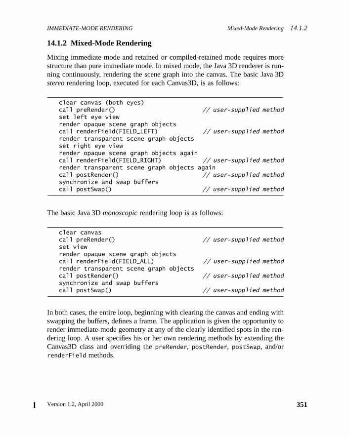
IMMEDIATE-MODE RENDERING Mixed-Mode Rendering14.1.2
orerun-a 3D
withty toren-the
14.1.2 Mixed-Mode Rendering
Mixing immediate mode and retained or compiled-retained mode requires mstructure than pure immediate mode. In mixed mode, the Java 3D renderer isning continuously, rendering the scene graph into the canvas. The basic Javstereorendering loop, executed for each Canvas3D, is as follows:
clear canvas (both eyes)call preRender() // user-supplied methodset left eye viewrender opaque scene graph objectscall renderField(FIELD_LEFT) // user-supplied methodrender transparent scene graph objectsset right eye viewrender opaque scene graph objects againcall renderField(FIELD_RIGHT) // user-supplied methodrender transparent scene graph objects againcall postRender() // user-supplied methodsynchronize and swap bufferscall postSwap() // user-supplied method
The basic Java 3Dmonoscopicrendering loop is as follows:
clear canvascall preRender() // user-supplied methodset viewrender opaque scene graph objectscall renderField(FIELD_ALL) // user-supplied methodrender transparent scene graph objectscall postRender() // user-supplied methodsynchronize and swap bufferscall postSwap() // user-supplied method
In both cases, the entire loop, beginning with clearing the canvas and endingswapping the buffers, defines a frame. The application is given the opportunirender immediate-mode geometry at any of the clearly identified spots in thedering loop. A user specifies his or her own rendering methods by extendingCanvas3D class and overriding thepreRender, postRender, postSwap, and/orrenderField methods.
351Version 1.2, April 2000
14.2 Canvas3D Methods IMMEDIATE-MODE RENDERING
352
are
Thisren-
ode,
D is
withist. Itnder-
. ASee
nyokesne for
New in 1.2
14.2 Canvas3D Methods
The Canvas3D methods that directly affect immediate-mode renderingdescribed here.
When a Canvas3D object is created, it is initially marked as being started.means that as soon as the Canvas3D is added to an active View object, thedering loop will render the scene graph to the canvas. In pure immediate mthe renderer must be stopped (via a call tostopRenderer) prior to adding thecanvas to an active View object.
Constants
public static final int FIELD_LEFTpublic static final int FIELD_RIGHTpublic static final int FIELD_ALL
These constants specify the field that the rendering loop for this Canvas3rendering. TheFIELD_LEFT and FIELD_RIGHT values indicate the left and rightfields of a field-sequential stereo rendering loop, respectively. TheFIELD_ALL
value indicates a monoscopic or single-pass stereo rendering loop.
Methods
public GraphicsContext3D getGraphicsContext3D()
This method retrieves the immediate-mode 3D graphics context associatedthis Canvas3D. It creates a new graphics context if one does not already exreturns a GraphicsContext3D object that can be used for immediate mode reing to this Canvas3D.
public J3DGraphics2D getGraphics2D()
This method returns the 2D graphics object associated with this Canvas3Dnew 2D graphics object is created if one does not already exist.Section 14.3.2, “J3DGraphics2D.”
public void preRender()
Applications that wish to perform operations in the rendering loop prior to aactual rendering must override this method. The Java 3D rendering loop invthis method after clearing the canvas and before any rendering has been dothis frame. Applications shouldnot call this method.
The Java 3D API Specification
IMMEDIATE-MODE RENDERING Canvas3D Methods 14.2
nyokesfore
ingthodiatedatrideffer
ver-ice,opic
sys-anyroup
iled-
merce.
If the
neren-
this
public void postRender()
Applications that wish to perform operations in the rendering loop following aactual rendering must override this method. The Java 3D rendering loop invthis method after completing all rendering to the canvas for this frame and bethe buffer swap. Applications shouldnot call this method.
public void postSwap()
Applications that wish to perform operations at the very end of the renderloop must override this method. The Java 3D rendering loop invokes this meafter completing all rendering to this canvas, and all other canvases assocwith the current view, for this frame following the buffer swap. Applications thwish to perform operations at the very end of the rendering loop may overthis function. In off-screen mode, all rendering is copied to the off-screen bubefore this method is called. Applications shouldnot call this method.
public void renderField(int fieldDesc)
Applications that wish to perform operations during the rendering loop must oride this function. The Java 3D rendering loop invokes this method, possibly twduring the loop. It is called once for each field (once per frame on a monoscsystem or once each for the right eye and left eye on a field-sequential stereotem). This method is called after all opaque objects are rendered and beforetransparent objects are rendered (subject to restrictions imposed by OrderedGnodes). This is intended for use by applications that want to mix retained/compretained mode rendering with some immediate-mode rendering. ThefieldDesc
parameter is the field description:FIELD_LEFT, FIELD_RIGHT, or FIELD_ALL.Applications that wish to work correctly in stereo mode should render the saimage for bothFIELD_LEFT andFIELD_RIGHT calls. If Java 3D calls the renderewith FIELD_ALL, the immediate-mode rendering needs to be done only onApplications shouldnot call this method.
public final void startRenderer()public final void stopRenderer()
These methods start or stop the Java 3D renderer for this Canvas3D object.Java 3D renderer is currently running whenstopRenderer is called, the render-ing will be synchronized before being stopped. No further rendering will be doto this canvas by Java 3D until the renderer is started again. If the Java 3Dderer is not currently running whenstartRenderer is called, any rendering toother Canvas3D objects sharing the same View will be synchronized beforeCanvas3D’s renderer is (re)started.
353Version 1.2, April 2000
14.3 API for Immediate Mode IMMEDIATE-MODE RENDERING
354
r thishas
uffer.h-hod
andceneo the
3Dt. Astate
edi-thehe
New in 1.2
public final boolean isRendererRunning()This method retrieves the state of the renderer for this Canvas3D object.
public void swap()
This method synchronizes and swaps buffers on a double-buffered canvas foCanvas3D object. This method should be called only if the Java 3D rendererbeen stopped. In the normal case, the renderer automatically swaps the bThis method calls theflush(true) methods of the associated 2D and 3D grapics contexts, if they have been allocated. If the application invokes this metand the canvas has a running Java 3D renderer, aRestrictedAccessException
exception is thrown. AnIllegalStateException is thrown if this Canvas3D isin off-screen mode.
14.3 API for Immediate Mode
The Java 3D immediate mode allows an application to set attributes directlydraw three-dimensional geometry using the same objects as in Java 3D sgraphs. An immediate-mode application renders by passing these objects tset anddraw methods of a GraphicsContext3D object.
14.3.1 GraphicsContext3D
The GraphicsContext3D object is used for immediate-mode rendering into acanvas. It is created by, and associated with, a specific Canvas3D objecGraphicsContext3D class defines methods that manipulate 3D graphicsattributes and draw 3D geometric primitives.
Note that the drawing methods in this class are not necessarily executed immately. They may be buffered up for future execution. Applications must callflush(boolean) method to ensure that the rendering actually happens. Tflush method is implicitly called in the following cases:
• ThereadRaster method callsflush(true).
• TheCanvas3D.swap method callsflush(true).
• The Java 3D renderer callsflush(true) prior to swapping the buffer fora double-buffered on-screen Canvas3D.
• The Java 3D renderer callsflush(true) prior to copying into the off-screen buffer of an off-screen Canvas3D.
• The Java 3D renderer callsflush(false) after calling thepreRender,renderField, postRender, andpostSwap Canvas3D callback methods.
The Java 3D API Specification
IMMEDIATE-MODE RENDERING GraphicsContext3D14.3.1
right
lica-ich
lica-
ew in 1.2
ew in 1.2
ew in 1.2
A single-buffered, pure-immediate mode application must explicitly callflush
to ensure that the graphics will be rendered to the Canvas3D.
Constants
public static final int STEREO_LEFTpublic static final int STEREO_RIGHTpublic static final int STEREO_BOTH
These constants specify whether rendering is done to the left eye, to theeye, or to both eyes.
Constructors
There are no publicly accessible constructors of GraphicsContext3D. An apption obtains a 3D graphics context object from the Canvas3D object into whthe application wishes to render by using thegetGraphicsContext3D method.
The Canvas3D object creates a new GraphicsContext3D the first time an apption invokesgetGraphicsContext3D. A new GraphicsContext3D initializes itsstate variables to the following defaults:
Methods
public Canvas3D getCanvas3D()
This method gets the Canvas3D that created this GraphicsContext3D.
Parameters Default Values
Background object null
Fog object null
ModelClip object null
Appearance object null
List of Light objects empty
High-Res coordinates (0, 0, 0,)
modelTransform identity
AuralAttributes object null
List of Sound objects empty
buffer override false
front buffer rendering false
stereo mode STEREO_BOTH
N
N
N
355Version 1.2, April 2000
14.3.1 GraphicsContext3D IMMEDIATE-MODE RENDERING
356
t usedspec-ualobjectbjectt of a
econ-
usedspec-ck-
nodet becene-tolica-
is 3DFogtheThe
y be
ren-
public void setAppearance(Appearance appearance)public Appearance getAppearance()
These methods access or modify the current Appearance component objecby this 3D graphics context. The graphics context stores a reference to theified Appearance object. This means that the application may modify individappearance attributes by using the appropriate methods on the Appearance(see Section 8.1.2, “Appearance Object”). The Appearance component omust not be part of a live scene graph, nor may it subsequently be made parlive scene graph—anIllegalSharingException is thrown in such cases. If theAppearance object isnull, default values will be used for all appearancattributes—it is as if an Appearance node were created using the defaultstructor.
public void setBackground(Background background)public Background getBackground()
These methods access or modify the current Background leaf node objectby this 3D graphics context. The graphics context stores a reference to theified Background node. This means that the application may modify the baground color or image by using the appropriate methods on the Backgroundobject (see Section 6.4, “Background Node”). The Background node must nopart of a live scene graph, nor may it subsequently be made part of a live sgraph—anIllegalSharingException is thrown in such cases. If the Background object isnull, the default background color of black (0,0,0) is usedclear the canvas prior to rendering a new frame. The Background node’s apption region is ignored for immediate-mode rendering.
public void setFog(Fog fog)public Fog getFog()
These methods access or modify the current Fog leaf node object used by thgraphics context. The graphics context stores a reference to the specifiednode. This means that the application may modify the fog attributes usingappropriate methods on the Fog node object (see Section 6.7, “Fog Node”).Fog node must not be part of a live scene graph, nor may it subsequentlmade part of a live scene graph—anIllegalSharingException is thrown insuch cases. If the Fog object isnull, fog is disabled. Both the region of influenceand the hierarchical scope of the Fog node are ignored for immediate-modedering.
The Java 3D API Specification
IMMEDIATE-MODE RENDERING GraphicsContext3D14.3.1
con-e
ex.ro-hehe
hts.the6.8,eh—an
ode
hicshod,h-
edpeci-
public void addLight(Light light)public void insertLight(Light light, int index)public void setLight(Light light, int index)public Light getLight(int index)public void removeLight(int index)public int numLights()public Enumeration getAllLights()
These methods access or modify the list of lights used by this 3D graphicstext. TheaddLight method adds a new light to the end of the list of lights. ThinsertLight method inserts a new light before the light at the specified indThesetLight method replaces the light at the specified index with the light pvided. TheremoveLight method removes the light at the specified index. TnumLights method returns a count of the number of lights in the list. TgetLight method returns the light at the specified index. ThegetAllLights
method retrieves the Enumeration object of all lights.
The graphics context stores a reference to each light object in the list of ligThis means that the application may modify the light attributes for any oflights using the appropriate methods on that Light node object (see Section“Light Node”). None of the Light nodes in the list of lights may be part of a livscene graph, nor may they subsequently be made part of a live scene grapIllegalSharingException is thrown in such cases. Adding anull Light objectto the list will result in aNullPointerException. Both the region of influenceand the hierarchical scope of all lights in the list are ignored for immediate-mrendering.
public void setHiRes(int x[], int y[], int z[])public void setHiRes(HiResCoord hiRes)public void getHiRes(HiResCoord hiRes)
These methods access or modify the high-resolution coordinates of this grapcontext to the location specified by the parameters provided. In the first metthe parametersx, y, andz are arrays of eight 32-bit integers that specify the higresolution coordinates point.
public void setModelTransform(Transform3D t)public void multiplyModelTransform(Transform3D t)public void getModelTransform(Transform3D t)
These methods access or modify the current model transform. Themultiply-
ModelTransform method multiplies the current model transform by the specifitransform and stores the result back into the current model transform. The sfied transformation must be affine. ABadTransformException is thrown (see
357Version 1.2, April 2000
14.3.1 GraphicsContext3D IMMEDIATE-MODE RENDERING
358
lle-
feringthis
modeis
s
e ren-into.
the
thodefer-od-lip
mayptionis-Clip
New in 1.2
New in 1.2
New in 1.2
New in 1.2
New in 1.2
New in 1.2
New in 1.2
New in 1.2
Section D.1, “BadTransformException”) if an attempt is made to specify an igal Transform3D.
public void setBufferOverride(boolean bufferOverride)public boolean getBufferOverride()
These methods set and retrieve a flag that specifies whether the double bufand stereo mode from the Canvas3D are overridden. When set to true,attribute enables thefrontBufferRendering andstereoMode attributes.
public void setFrontBufferRendering(boolean frontBufferRendering)public boolean getFrontBufferRendering()
These methods set and retrieve a flag that enables or disables immediaterendering into the front buffer of a double buffered Canvas3D. This attributeused only when thebufferOverride flag is enabled. Note that this attribute hano effect if double buffering is disabled or is not available on the Canvas3D.
public void setStereoMode(int stereoMode)public int getStereoMode()
These methods set and retrieve the current stereo mode for immediate moddering. The parameter specifies which stereo buffer or buffers are renderedThis attribute is used only when thebufferOverride flag is enabled. The stereomode is one of the following:STEREO_LEFT, STEREO_RIGHT, or STEREO_BOTH.Note that this attribute has no effect if stereo is disabled or is not available onCanvas3D.
public void setModelClip(ModelClip modelClip)public ModelClip getModelClip()
These methods set and retrieve the current ModelClip leaf node. The set mesets the ModelClip to the specified object. The graphics context stores a rence to the specified ModelClip node. This means that the application may mify the model clipping attributes using the appropriate methods on the ModelCnode object. The ModelClip node must not be part of a live scene graph, norit subsequently be made part of a live scene graph—an IllegalSharingExceis thrown in such cases. If the ModelClip object is null, model clipping is dabled. Both the region of influence and the hierarchical scope of the Modelnode are ignored for immediate-mode rendering.
The Java 3D API Specification
IMMEDIATE-MODE RENDERING GraphicsContext3D14.3.1
jecto theify
ral-l-y it
re
con-on-e
thi-f
..
unds.the(see
maylive
ay-nd’s
public void setAuralAttributes(AuralAttributes attributes)public AuralAttributes getAuralAttributes()
These methods access or modify the current AuralAttributes component obused by this 3D graphics context. The graphics context stores a reference tspecified AuralAttributes object. This means that the application may modindividual audio attributes by using the appropriate methods in the AuAttributes object (see Section 8.1.17, “AuralAttributes Object”). The AuraAttributes component object must not be part of a live scene graph, nor masubsequently be made part of a live scene graph—anIllegalSharingExcep-
tion is thrown in such cases. If the AuralAttributes object isnull, default valueswill be used for all audio attributes—it is as if an AuralAttributes object wecreated using the default constructor.
public void addSound(Sound sound)public void insertSound(Sound sound, int index)public void setSound(Sound sound, int index)public Sound getSound(int index)public void removeSound(int index)public int numSounds()public boolean isSoundPlaying(int index)public Enumeration getAllSounds()
These methods access or modify the list of sounds used by this 3D graphicstext. TheaddSound method appends the specified sound to this graphics ctext’s list of sounds. TheinsertSound method inserts the specified sound at thspecified index location. ThesetSound method replaces the specified sound withe sound provided. TheremoveSound method removes the sound at the specfied index location. ThenumSounds method retrieves the current number osounds in this graphics context. ThegetSound method retrieves the index-selected sound. TheisSoundPlaying method retrieves the sound-playing flagThegetAllSounds method retrieves the Enumeration object of all the sounds
The graphics context stores a reference to each sound object in the list of soThis means that the application may modify the sound attributes for any ofsounds by using the appropriate methods on that Sound node objectSection 6.9, “Sound Node”). None of the Sound nodes in the list of soundsbe part of a live scene graph, nor may they subsequently be made part of ascene graph—anIllegalSharingException is thrown in such cases. Adding anull Sound object to the list results in aNullPointerException. If the list ofsounds is empty, sound rendering is disabled.
Adding or inserting a sound to the list of sounds implicitly starts the sound pling. Once a sound is finished playing, it can be restarted by setting the sou
359Version 1.2, April 2000
14.3.2 J3DGraphics2D IMMEDIATE-MODE RENDERING
360
or
ge-asternentthis
data
rrent
the
al to
pe3D
wing
to aublicixedns asavaure-
being
New in 1.2
New in 1.2
enable flag totrue. The scheduling region of all sounds in the list is ignored fimmediate-mode rendering.
public void readRaster(Raster raster)
This method reads an image from the frame buffer and copies it into the ImaComponent or DepthComponent objects referenced by the specified Robject. All parameters of the Raster object and the component ImageCompoor DepthComponent objects must be set to the desired values prior to callingmethod. These values determine the location, size, and format of the pixelthat is read. This method callsflush(true) prior to reading the frame buffer.
public void clear()
This method clears the canvas to the color or image specified by the cuBackground leaf node object.
public void draw(Geometry geometry)public void draw(Shape3D shape)
The firstdraw method draws the specified Geometry component object usingcurrent state in the graphics context. The seconddraw method draws the speci-fied Shape3D leaf node object. This is a convenience method that is identiccalling thesetAppearance(Appearance) anddraw(Geometry) methods passingthe Appearance and Geometry component objects of the specified Shanodes as arguments.
public void flush(boolean wait)
This method flushes all previously executed rendering operations to the drabuffer for this 3D graphics context. Thewait parameter indicates whether towait for the rendering to complete before returning from this call.
14.3.2 J3DGraphics2D
The J3DGraphics2D class extends Graphics2D to provide 2D rendering inCanvas3D. It is an abstract base class that is further extended by a non-pJava 3D implementation class. This class allows Java 2D rendering to be mwith Java 3D rendering in the same Canvas3D, subject to the same restrictioimposed for 3D immediate-mode rendering: In mixed-mode rendering, all J2D requests must be done from one of the Canvas3D callback methods; in pimmediate mode, the Java 3D renderer must be stopped for the Canvas3Drendered into.
The Java 3D API Specification
IMMEDIATE-MODE RENDERING J3DGraphics2D14.3.2
s3D
st.
omd up
lled
wing
D is
ia a
ew in 1.2
ew in 1.2
ew in 1.2
ew in 1.2
ew in 1.2
ew in 1.2
An application obtains a Java 3D 2D graphics context object from the Canvaobject that the application wishes to render into by using thegetGraphics2D
method. A new J3DGraphics2D object is created if one does not already exi
Note that the drawing methods in this class, including those inherited frGraphics2D, are not necessarily executed immediately. They may be bufferefor future execution. Applications must call theflush(boolean) method toensure that the rendering actually happens. The flush method is implicitly cain the following cases:
• TheCanvas3D.swap method callsflush(true).
• The Java 3D renderer callsflush(true) prior to swapping the buffer fora double-buffered on-screen Canvas3D.
• The Java 3D renderer callsflush(true) prior to copying into the off-screen buffer of an off-screen Canvas3D.
• The Java 3D renderer callsflush(false) after calling thepreRender,renderField, postRender, andpostSwap Canvas3D callback methods.
A single-buffered, pure-immediate mode application must explicitly callflush
to ensure that the graphics will be rendered to the Canvas3D.
Methods
public abstract void flush(boolean wait)
This method flushes all previously executed rendering operations to the drabuffer for this 2D graphics object.
public final Graphics create()public final Graphics create(int x, int y, int width, int height)
These methods are not supported. The only way to obtain a J3DGraphics2from the associated Canvas3D.
public final void setBackground(Color color)public final Color getBackground()public final void clearRect(int x, int y, int width, int height)
These methods are not supported. Clearing a Canvas3D is done implicitly vBackground node in the scene graph or explicitly via theclear method in a 3Dgraphics context.
N
N
N
N
N
N
361Version 1.2, April 2000

Version 1.2, April 2000
A P P E N D I X A
tejectsriate
y andnot
s willepa-
r-ele-
ent
blic
Math Objects
M ATHEMATICAL objects allow Java 3D users to represent and manipulalow-level mathematical constructs such as vectors and matrices. Math obalso define specific operations that allow users to manipulate them in appropways.
Java 3D needs these vector and matrix math classes. It uses them internallalso makes them available to applications for their use. However, they arepart of Java 3D. Rather, they are defined here for convenience. These classebecome more widely distributed, which is why Java 3D defines them as a sratejavax.vecmath package. Figure A-1 shows the math object hierarchy.
A.1 Tuple Objects
Java 3D uses tuple objects to represent and manipulate two-, three-, and foument values.
A.1.1 Tuple2d Class
The Tuple2d class is used for points and vectors. This class is a two-elemtuple that is represented by double-precision floating-pointx,y coordinates.
Variables
The component values of a Tuple2d are directly accessible through the puvariablesx and y. To access thex component of a Tuple2d calledupperLeft-Corner, a programmer would writeupperLeftCorner.x. The programmerwould access they component similarly.
363

A.1.1 Tuple2d Class MATH OBJECTS
364
Figure A-1 Math Object Hierarchy
Tuple ObjectsTuple2d
Point2dVector2d
Tuple2fPoint2fTexCoord2fVector2f
Tuple3bColor3b
Tuple3dPoint3dVector3d
Tuple3fColor3fPoint3fTexCoord3fVector3f
Tuple3iPoint3i
Tuple4bColor4b
Tuple4dPoint4dQuat4dVector4d
Tuple4fColor4fPoint4fQuat4fVector4f
Tuple4iPoint4i
AxisAngle4dAxisAngle4fGVector
Matrix ObjectsMatrix3fMatrix3dMatrix4fMatrix4dGMatrix
The Java 3D API Specification
MATH OBJECTS Tuple2d Class A.1.1
gen-
y
edeis
ofor
public double xPublic double y
Thex andy coordinates, respectively.
Constructors
public Tuple2d(double x, double y)public Tuple2d(double[] t)public Tuple2d(Tuple2d t1)public Tuple2d(Tuple2f t1)public Tuple2d()
Each of these five constructors returns a new Tuple2d. The first constructorerates a Tuple2d from two double-precision floating-point numbersx andy. Thesecond constructor generates a Tuple2d from the first two elements of arrat.The third and fourth constructors generate a Tuple2d from the tuplet1. The finalconstructor generates a Tuple2d with the value of (0.0, 0.0).
Methods
public final void set(double x, double y)public final void set(double[] t)public final void set(Tuple2d t1)public final void set(Tuple2f t1)public final void get(double[] t)
The firstset method sets the value of this tuple to the specifiedxy coordinates.The secondset method sets the value of this tuple from the two values specifiin the arrayt. The third and fourthset methods set the value of this tuple to thvalue of the tuplet1. The get method copies the value of the elements of thtuple into the arrayt.
public final void add(Tuple2d t1, Tuple2d t2)public final void add(Tuple2d t1)public final void sub(Tuple2d t1, Tuple2d t2)public final void sub(Tuple2d t1)
The firstadd method sets the value of this tuple to the vector sum of tuplesv1
andv2. The secondadd method sets the value of this tuple to the vector sumitself and tuplet1. The firstsub method sets the value of this tuple to the vectdifference of tuplet1 andt2 (this = t1 – t2). The secondsub method sets thevalue of this tuple to the vector difference of itself and tuplet1 (this = this – t1).
365Version 1.2, April 2000
A.1.1 Tuple2d Class MATH OBJECTS
366
e
e and
rst
ple
public final void negate(Tuple2d t1)public final void negate()
The firstnegate method sets the value of this tuple to the negation of tuplet1.The second method negates the value of this vector in place.
public final void scale(double s, Tuple2d t1)public final void scale(double s)public final void scaleAdd(double s, Tuple2d t1)public final void scaleAdd(double s, Tuple2d t1, Tuple2d t2)
The firstscale method multiplies each element of the tuplet1 by the scale fac-tor s and places the resulting scaled tuple intothis. The second method multi-plies each element of this tuple by the scale factors and places the resultingscaled tuple intothis. The firstscaleAdd method scales this tuple by the scalfactor s, adds the result to tuplet1, and places the result into the tuplethis(this = s*this + t1). The secondscaleAdd method scales tuplet1 by the scalefactor s, adds the result to tuplet1, then places the result into the tuplethis(this = s*t1 + t2).
public final void absolute(Tuple2d t)
This method sets each component of the tuple parameter to its absolute valuplaces the modified values into this tuple.
public final void clamp(double min, double max)public final void clamp(double min, double max, Tuple2d t)public final void clampMin(double min)public final void clampMin(double min, Tuple2d t)public final void clampMax(double max)public final void clampMax(double max, Tuple2d t)
The first clamp method clamps this tuple to the range [min, max]. The secondclamp method clamps the values from tuplet to the range [min, max] and assignsthese clamped values to this tuple. The firstclampMin method clamps each valueof this tuple to themin parameter. The secondclampMin method clamps eachvalue of the tuplet and assigns these clamped values to this tuple. The ficlampMax method clamps each value of this tuple to themax parameter. The sec-ond clampMax method clamps each value of tuplet to the max parameter andassigns these clamped values to this tuple. In each method the values of tut
remain unchanged.
The Java 3D API Specification
MATH OBJECTS Tuple2d Class A.1.1
lin-
rue if
s
thisis,tsis is
pre-
public final void interpolate(Tuple2d t1, Tuple2d t2, double alpha)public final void interpolate(Tuple2d t1, double alpha)
The first method linearly interpolates between tuplest1 and t2 and places theresult into this tuple (this = (1 – alpha) * t1 + alpha * t2). The second methodearly interpolates between this tuple and tuplet1 and places the result into thistuple (this = (1 – alpha) * this + alpha * t1).
public boolean equals(Tuple2d t1)public boolean equals(Object t1)
The first method returnstrue if all of the data members of tuplet1 are equal tothe corresponding data members in this tuple. The second method returns tthe Objectt1 is of type Tuple2d and all of the data members oft1 are equal tothe corresponding data members in this Tuple2d.
public boolean epsilonEquals(Tuple2d t1, double epsilon)
This method returnstrue if the L∞ distance between this tuple and tuplet1 isless than or equal to theepsilon parameter. Otherwise, this method returnfalse. The L∞ distance is equal to
public int hashCode()
The hashCode method returns a hash number based on the data values inobject. Two Tuple2d objects with identical data values (thatequals(Tuple2d) returnstrue) will return the same hash number. Two objecwith different data members may return the same hash number, although thnot likely.
public String toString()
This method returns a string that contains the values of this Tuple2d.
A.1.1.1 Point2d Class
The Point2d class extends Tuple2d. The Point2d is a two-element point resented by double-precision floating-pointx,y coordinates.
Constructors
public Point2d(double x, double y)public Point2d(double p[])public Point2d(Point2d p1)
MAX abs x1 x2–( ) abs y1 y2–( ),[ ]
367Version 1.2, April 2000
A.1.1 Tuple2d Class MATH OBJECTS
368
uctor
array
ce
nt
pre-
public Point2d(Point2f p1)public Point2d(Tuple2d t1)public Point2d(Tuple2f t1)public Point2d()
Each of these seven constructors returns a new Point2d. The first constrgenerates a Point2d from two double-precision floating-point numbersx and y.The second constructor generates a Point2d from the first two elements ofp. The third and fourth constructors generate a Point2d from the pointp1. Thefifth and sixth constructors generate a Point2d from the tuplet1. The final con-structor generates a Point2d with the value of (0.0, 0.0).
Methods
public final double distanceSquared(Point2d p1)public final double distance(Point2d p1)
The distanceSquared method computes the square of the Euclidean distanbetween this point and pointp1 and returns the result. Thedistance methodcomputes the Euclidean distance between this point and pointp1 and returns theresult.
public final double distanceL1(Point2d p1)
This method computes the L1 (Manhattan) distance between this point and poip1. The L1 distance is equal to
public final double distanceLinf(Point2d p1)
This method computes the L∞ distance between this point and pointp1. The L∞distance is equal to
A.1.1.2 Vector2d Class
The Vector2d class extends Tuple2d. The Vector2f is a two-element vector resented by double-precision floating-pointx,y coordinates.
Constructors
public Vector2d(double x, double y)public Vector2d(double v[])
abs x1 x2–( ) abs y1 y2–( )+
MAX abs x1 x2–( ) abs y1 y2–( ),[ ]
The Java 3D API Specification
MATH OBJECTS Tuple2f Class A.1.2
uctor
torThe
ing
public Vector2d(Vector2d v1)public Vector2d(Vector2f v1)public Vector2d(Tuple2d t1)public Vector2d(Tuple2f t1)public Vector2d()
Each of these seven constructors returns a new Vector2d. The first constrgenerates a Vector2d from two floating-point numbersx andy. The second con-structor generates a Vector2d from the first two elements of arrayv. The thirdand fourth constructors generate a Vector2d from the vectorv1. The fifth andsixth constructors generate a Vector2d from the specified tuplet1. The final con-structor generates a Vector2d with the value of (0.0, 0.0).
Methods
public final double dot(Vector2d v1)
Thedot method computes the dot product between this vector and vectorv1 andreturns the resulting value.
public final double lengthSquared()public final double length()
The lengthSquared method computes the square of the length of the vecthis and returns its length as a double-precision floating-point number.length method computes the length of the vectorthis and returns its length asa double-precision floating-point number.
public final void normalize(Vector2d v1)public final void normalize()
The firstnormalize method normalizes the vectorv1 to unit length and placesthe result inthis. The secondnormalize method normalizes the vectorthisand places the resulting unit vector back intothis.
public final double angle(Vector2d v1)
This method returns the angle, in radians, between this vector and vectorv1. Thereturn value is constrained to the range [0,π].
A.1.2 Tuple2f Class
The Tuple2f class is a generic two-element tuple used mostly for specifypoints and vectors made up of single-precision floating-pointx,y coordinates.
369Version 1.2, April 2000
A.1.2 Tuple2f Class MATH OBJECTS
370
blic
gen-
-
Variables
The component values of a Tuple2f are directly accessible through the puvariablesx andy. To access thex component of a Tuple2f calledupperLeftCor-ner, a programmer would writeupperLeftCorner.x. The programmer wouldaccess they component similarly.
public float xpublic float y
Thex andy coordinates, respectively.
Constructors
public Tuple2f(float x, float y)public Tuple2f(float t[])public Tuple2f(Tuple2f t1)public Tuple2f(Tuple2d t1)public Tuple2f()
Each of these five constructors returns a new Tuple2f. The first constructorerates a Tuple2f from two floating-point numbersx andy. The second constructorgenerates a Tuple2f from the first two elements of arrayt. The third and fourthconstructors generate a Tuple2f from the tuplet1. The final constructor gener-ates a Tuple2f with the value of (0.0, 0.0).
Methods
public final void set(float x, float y)public final void set(float t[])public final void set(Tuple2f t1)punlic final void set(Tiple2d t1)public final void get(float t[])
The set methods set the value of tuplethis to the values provided. Thegetmethod copies the values of the elements of this tuple into the arrayt.
public final void add(Tuple2f t1, Tuple2f t2)public final void add(Tuple2f t1)public final void sub(Tuple2f t1, Tuple2f t2)public final void sub(Tuple2f t1)
The firstadd method computes the element-by-element sum of tuplest1 andt2,placing the result inthis. The secondadd method computes the element-by-element sum of this tuple and tuplet1, placing the result inthis. The first submethod performs an element-by-element subtraction of tuplet2 from tuple t1
The Java 3D API Specification
MATH OBJECTS Tuple2f Class A.1.2
ues
e
utehe
and places the result inthis (this = t1 – t2). The secondsub method performs anelement-by-element subtraction oft1 from this and places the result inthis(this = this – t1).
public final void negate(Tuple2f t1)public final void negate()
The firstnegate method sets the values of this tuple to the negative of the valfrom tuplet1. The secondnegate method negates the tuplethis and places theresulting tuple back intothis.
public final void scale(float s, Tuple2f t1)public final void scale(float s)public final void scaleAdd(float s, Tuple2f t1)public final void scaleAdd(float s, Tuple2f t1, Tuple2f t2)
The firstscale method multiplies each element of the tuplet1 by the scale fac-tor s and places the resulting scaled tuple intothis. The secondscale methodmultiplies each element of this tuple by the scale factors and places the resultingscaled tuple intothis. The firstscaleAdd method scales this tuple by the scalfactor s, adds the result to tuplet1, and places the result into the tuplethis(this = s*this + t1). The secondscaleAdd method scales tuplet1 by the scalefactor s, adds the result to tuplet2, then places the result into the tuplethis(this = s*t1 + t2).
public final void absolute()public final void absolute(Tuple2f t)
The first absolute method sets each component of this tuple to its absolvalue. The secondabsolute method sets each component of this tuple to tabsolute value of the corresponding component in tuplet.
public final void clamp(float min, float max)public final void clamp(float min, float max, Tuple2f t)public final void clampMin(float min)public final void clampMin(float min, Tuple2f t)public final void clampMax(float max)public final void clampMax(float max, Tuple2f t)
The firstclamp method clamps this tuple to the range [min, max]. The secondclampmethod clamps the values from tuplet to the range [min, max] and assigns theseclamped values to this tuple. The firstclampMin method clamps each value of thistuple to themin parameter. The secondclampMin method clamps each value of thetuplet and assigns these clamped values to this tuple. The firstclampMax methodclamps each value of this tuple to themax parameter. The secondclampMax method
371Version 1.2, April 2000
A.1.2 Tuple2f Class MATH OBJECTS
372
es
lin-
rue if
s
this
ta
pre-
clamps each value of tuplet to themax parameter and assigns these clamped valuto this tuple. In each method the values of tuplet remain unchanged.
public final void interpolate(Tuple2f t1, Tuple2f t2, float alpha)public final void interpolate(Tuple2f t1, float alpha)
The first method linearly interpolates between tuplest1 and t2 and places theresult into this tuple (this = (1 – alpha) * t1 + alpha * t2). The second methodearly interpolates between this tuple and tuplet1 and places the result into thistuple (this = (1 – alpha) * this + alpha * t1).
public boolean equals(Tuple2f t1)public boolean equals(Object t1)
The first method returnstrue if all of the data members of tuplet1 are equal tothe corresponding data members in this tuple. The second method returns tthe Objectt1 is of type Tuple2f and all of the data members oft1 are equal tothe corresponding data members in this Tuple2f.
public boolean epsilonEquals(Tuple2f t1, float epsilon)
This method returnstrue if the L∞ distance between this tuple and tuplet1 isless than or equal to theepsilon parameter. Otherwise, this method returnfalse. The L∞ distance is equal to
public int hashCode()
The hashCode method returns a hash number based on the data values inobject. Two Tuple2f objects with identical data values (that is,equals(Tuple2f)
returnstrue) will return the same hash number. Two objects with different damembers may return the same hash number, although this is not likely.
public String toString()
This method returns a string that contains the values of this Tuple2f.
A.1.2.1 Point2f Class
The Point2f class extends Tuple2f. The Point2f is a two-element point resented by single-precision floating-pointx,y coordinates.
MAX abs x1 x2–( ) abs y1 y2–( ),[ ]
The Java 3D API Specification
MATH OBJECTS Tuple2f Class A.1.2
gen-
a
ce
nt
pre-
Constructors
public Point2f(float x, float y)public Point2f(float p[])public Point2f(Point2f p1)public Point2f(Point2d p1)public Point2f(Tuple2f t1)public Point2f(Tuple2f t1)public Point2f()
Each of these seven constructors returns a new Point2f. The first constructorerates a Point2f from two floating-point numbersx andy. The second constructorgenerates a Point2f from the first two elements of arrayp. The third and fourthconstructors generate a Point2f from the pointp1. The fifth and sixth construc-tors generate a Point2f from the tuplet1. The final constructor generatesPoint2f with the value of (0.0, 0.0).
Methods
public final float distanceSquared(Point2f p1)public final float distance(Point2f p1)
The distanceSquared method computes the square of the Euclidean distanbetween this point and pointp1 and returns the result. Thedistance methodcomputes the Euclidean distance between this point and pointp1 and returns theresult.
public final float distanceL1(Point2f p1)
This method computes the L1 (Manhattan) distance between this point and poip1. The L1 distance is equal to
public final float distanceLinf(Point2f p1)
This method computes the L∞ distance between this point and pointp1. The L∞distance is equal to
A.1.2.2 Vector2f Class
The Vector2f class extends Tuple2f. The Vector2f is a two-element vector resented by single-precision floating-pointx,y coordinates.
abs x1 x2–( ) abs y1 y2–( )+
MAX abs x1 x2–( ) abs y1 y2–( ),[ ]
373Version 1.2, April 2000
A.1.2 Tuple2f Class MATH OBJECTS
374
uctor
torhe
Constructors
public Vector2f(float x, float y)public Vector2f(float v[])public Vector2f(Vector2f v1)public Vector2f(Vector2d v1)public Vector2f(Tuple2f t1)public Vector2f(Tuple2d t1)public Vector2f()
Each of these seven constructors returns a new Vector2f. The first constrgenerates a Vector2f from two floating-point numbersx andy. The second con-structor generates a Vector2f from the first two elements of arrayv. The third andfourth constructors generate a Vector2f from the vectorv1. The fifth and sixthconstructors generate a Vector2f from the specified tuplet1. The final construc-tor generates a Vector2f with the value of (0.0, 0.0).
Methods
public final float dot(Vector2f v1)
Thedot method computes the dot product between this vector and vectorv1 andreturns the resulting value.
public final float lengthSquared()public final float length()
The lengthSquared method computes the square of the length of the vecthis and returns its length as a single-precision floating-point number. Tlength method computes the length of the vectorthis and returns its length asa single-precision floating-point number.
public final void normalize(Vector2f v1)public final void normalize()
The firstnormalize method normalizes the vectorv1 to unit length and placesthe result inthis. The secondnormalize method normalizes the vectorthisand places the resulting unit vector back intothis.
public final float angle(Vector2f v1)
This method returns the angle, in radians, between this vector and vectorv1. Thereturn value is constrained to the range [0,π].
The Java 3D API Specification
MATH OBJECTS Tuple3b Class A.1.3
ent
ctor
uple.How-55].resenttheriable
blic
s
A.1.2.3 TexCoord2f Class
The TexCoord2f class is a subset of Tuple2f. The TexCoord2f is a two-elemvector represented by single-precision floating-pointx,y coordinates.
Constructors
public TexCoord2f(float x, float y)public TexCoord2f(float v[])public TexCoord2f(TexCoord2f v1)public TexCoord2f(Tuple2f t1)public TexCoord2f()
Each of these five constructors returns a new TexCoord2f. The first construgenerates a TexCoord2f from two floating-point numbersx and y. The secondconstructor generates a TexCoord2f from the first two elements of arrayv. Thethird constructor generates a TexCoord2f from the TexCoord2fv1. The fourthconstructor generates a TexCoord2f from the Tuple2ft1. The final constructorgenerates a TexCoord2f with the value of (0.0, 0.0).
A.1.3 Tuple3b Class
The Tuple3b class is used for colors. This class represents a three-byte tNote that Java defines a byte as a signed integer in the range [–128, 127].ever, colors are more typically represented by values in the range [0, 2Java 3D recognizes this and, in those cases where Tuple3b is used to repcolor, treats the bytes as if the range were [0, 255]—in other words, as ifbytes were unsigned. Values greater than 127 can be assigned to a byte vausing a type cast. For example,
byteVariable = (byte) intValue;// intValue can be > 127
If intValue is greater than 127, thenbyteVariable will be negative. The correctvalue will be extracted when it is used (by masking off the upper bits).
Variables
The component values of a Tuple3b are directly accessible through the puvariablesx, y, and z. To access thex (red) component of a Tuple3b calledmyColor, a programmer would writemyColor.x. The programmer would accesthey (green) andz (blue) components similarly.
375Version 1.2, April 2000
A.1.3 Tuple3b Class MATH OBJECTS
376
gen--
e
s true
public byte xpublic byte ypublic byte z
The red, green, and blue values, respectively.
Constructors
public Tuple3b(byte b1, byte b2, byte b3)public Tuple3b(byte t[])public Tuple3b(Tuple3b t1)public Tuple3b()
Each of these four constructors returns a new Tuple3b. The first constructorerates a Tuple3b from three bytesb1, b2, andb3. The second constructor generates a Tuple3b from the first three elements of arrayt. The third constructorgenerates a Tuple3b from the byte-precision Tuple3bt1. The final constructorgenerates a Tuple3b with the value of (0.0, 0.0, 0.0).
Methods
public String toString()
This method returns a string that contains the values of this Tuple3b.
public final void set(byte t[])public final void set(Tuple3b t1)public final void get(byte t[])public final void get(Tuple3b t1)
The first set method sets the values of thex, y, and z data members of thisTuple3b to the values in the arrayt of length three. The secondset method setsthe values of thex, y, andz data members of this Tuple3b to the values in thargument tuplet1. The firstget method places the values of thex, y, andz com-ponents of this Tuple3b into the arrayt of length three. The secondget methodplaces the values of thex, y, andz components of this Tuple3b into the tuplet1.
public boolean equals(Tuple3b t1)public boolean equals(Object t1)
The first method returnstrue if all of the data members of Tuple3bt1 are equalto the corresponding data members in this tuple. The second method returnif the Objectt1 is of type Tuple3b and all of the data members oft1 are equal tothe corresponding data members in this Tuple3b.
The Java 3D API Specification
MATH OBJECTS Tuple3d Class A.1.4
. Two
ta
gen--
br3b
thet
reci-
ew in 1.2
ew in 1.2
ew in 1.2
public int hashCode()
This method returns a hash number based on the data values in this objectdifferent Tuple3b objects with identical data values (that is,equals(Tuple3b)
returnstrue) will return the same hash number. Two tuples with different damembers may return the same hash value, although this is not likely.
A.1.3.1 Color3b Class
The Color3b class extends Tuple3b and represents three-byte color values.
Constructors
public Color3b(byte c1, byte c2, byte c3)public Color3b(byte c[])public Color3b(Color3b c1)public Color3b(Tuple3b t1)public Color3b(Color color)public Color3b()
Each of these five constructors returns a new Color3b. The first constructorerates a Color3b from three bytesc1, c2, andc3. The second constructor generates a Color3b from the first three elements of arrayc. The third constructorgenerates a Color3b from the byte-precision Color3bc1. The fourth constructorgenerates a Color3b from the tuplet1. The fifth constructor generates a Color3from the specified AWT Color object. The final constructor generates a Colowith the value of (0.0, 0.0, 0.0).
Methods
public final void set(Color color)public final Color get()
The set method sets the R,G,B values of this Color3b object to those ofspecified AWT Color object. Theget method returns a new AWT Color objecinitialized with the R,G,B values of this Color3b object.
A.1.4 Tuple3d Class
The Tuple3d class is a generic three-element tuple represented by double-psion floating-pointx, y, andz coordinates.
N
N
N
377Version 1.2, April 2000
A.1.4 Tuple3d Class MATH OBJECTS
378
blic
gen-
Variables
The component values of a Tuple3d are directly accessible through the puvariablesx, y, andz. To access thex component of a Tuple3d calledupperLeft-Corner, a programmer would writeupperLeftCorner.x. The programmerwould access they andz components similarly.
public double xpublic double ypublic double z
Thex, y, andz coordinates, respectively.
Constructors
public Tuple3d(double x, double y, double z)public Tuple3d(double t[])public Tuple3d(Tuple3d t1)public Tuple3d(Tuple3f t1)public Tuple3d()
Each of these five constructors returns a new Tuple3d. The first constructorerates a Tuple3d from three floating-point numbersx, y, andz. The second con-structor generates a Tuple3d from the first three elements of arrayt. The thirdconstructor generates a Tuple3d from the double-precision Tuple3dt1. Thefourth constructor generates a Tuple3d from the single-precision Tuple3ft1. Thefinal constructor generates a Tuple3d with the value of (0.0, 0.0, 0.0).
Methods
public final void set(double x, double y, double z)public final void set(double t[])public final void set(Tuple3d t1)public final void set(Tuple3f t1)public final void get(double t[])public final void get(Tuple3d t)
The fourset methods set the value of tuplethis to the values specified or to thevalues of the specified vectors. The twoget methods copy thex, y, andz valuesinto the arrayt of length three.
The Java 3D API Specification
MATH OBJECTS Tuple3d Class A.1.4
ues
m is
public final void add(Tuple3d t1, Tuple3d t2)public final void add(Tuple3d t1)public final void sub(Tuple3d t1, Tuple3d t2)public final void sub(Tuple3d t1)
The firstadd method computes the element-by-element sum of tuplest1 andt2and places the result inthis. The secondadd method computes the ele-ment-by-element sum of this tuple and tuplet1 and places the result intothis.The first sub method performs an element-by-element subtraction of tuplet2
from tuple t1 and places the result inthis (this = t1 – t2). The secondsubmethod performs an element-by-element subtraction of tuplet1 from this tupleand places the result inthis (this = this – t1).
public final void negate(Tuple3d t1)public final void negate()
The firstnegate method sets the values of this tuple to the negative of the valfrom tuplet1. The secondnegate method negates the tuplethis and places theresulting tuple back intothis.
public final void scaleAdd(double s, Tuple3f t1)
A deprecated method. See method below.
public final void scale(double s, Tuple3d t1)public final void scale(double s)public final void scaleAdd(double s, Tuple3d t1)public final void scaleAdd(double s, Tuple3d t1, Tuple3d t2)
The firstscale method multiplies each element of the tuplet1 by the scale fac-tor s and places the resulting scaled tuple intothis. The secondscale methodmultiplies each element ofthis tuple by the scale factors and places the result-ing scaled tuple back intothis. The firstscaleAdd method scales this tuple bythe scale factors, adds the result to tuplet1, and places the result into tuplethis(this = s*this + t1). The secondscaleAdd method scales the tuplet1 by the scalefactors, adds the result to the tuplet2, and places the result into the tuplethis(this = s*t1 + t2).
public String toString()
This method returns a string that contains the values of this Tuple3d. The for(x, y, z).
379Version 1.2, April 2000
A.1.4 Tuple3d Class MATH OBJECTS
380
. Two
ta
turns
s
utehe
public int hashCode()
This method returns a hash number based on the data values in this objectdifferent Tuple3d objects with identical data values (that is,equals(Tuple3d)
returnstrue) will return the same hash number. Two tuples with different damembers may return the same hash value, although this is not likely.
public boolean equals(Tuple3d v1)public boolean equals(Object t1)
The first method returnstrue if all of the data members of Tuple3dv1 are equalto the corresponding data members in this Tuple3d. The second method retrue if the Objectt1 is of type Tuple3d and all of the data members oft1 areequal to the corresponding data members in this Tuple3d.
public boolean epsilonEquals(Tuple3d t1, double epsilon)
This method returnstrue if the L∞ distance between this tuple and tuplet1 isless than or equal to theepsilon parameter. Otherwise, this method returnfalse. The L∞ distance is equal to
public final void absolute()public final void absolute(Tuple3d t)
The first absolute method sets each component of this tuple to its absolvalue. The secondabsolute method sets each component of this tuple to tabsolute value of the corresponding component in tuplet.
public final void clamp(float min, float max)public final void clamp(float min, float max, Tuple3d t)public final void clampMin(float min)public final void clampMin(float min, Tuple3d t)public final void clampMax(float max)public final void clampMax(float max, Tuple3d t)
Deprecated methods. See the next six methods.
public final void clamp(double min, double max)public final void clamp(double min, double max, Tuple3d t)public final void clampMin(double min)public final void clampMin(double min, Tuple3d t)public final void clampMax(double max)public final void clampMax(double max, Tuple3d t)
MAX abs x1 x2–( ) abs y1 y2–( ) abs z1 z2–( ),,[ ]
The Java 3D API Specification
MATH OBJECTS Tuple3d Class A.1.4
rst
ple
nd
epre-
uctor
The first clamp method clamps this tuple to the range [min, max]. The secondclamp method clamps the values from tuplet to the range [min, max] and assignsthese clamped values to this tuple. The firstclampMin method clamps each valueof this tuple to themin parameter. The secondclampMin method clamps eachvalue of the tuplet and assigns these clamped values to this tuple. The ficlampMax method clamps each value of this tuple to themax parameter. The sec-ond clampMax method clamps each value of tuplet to the max parameter andassigns these clamped values to this tuple. In each method, the values of tut
remain unchanged.
public final void interpolate(Tuple3d t1, Tuple3d t2, float alpha)public final void interpolate(Tuple3d t1, float alpha)
Deprecated methods. See the next two methods.
public final void interpolate(Tuple3d t1, Tuple3d t2, double alpha)public final void interpolate(Tuple3d t1, double alpha)
The firstinterpolate method linearly interpolates between tuplest1 andt2 andplaces the result into this tuple (this = (1 – alpha) * t1 + alpha * t2). The secointerpolate method linearly interpolates between this tuple and tuplet1 andplaces the result into this tuple (this = (1 – alpha) * this + alpha * t1).
A.1.4.1 Point3d Class
The Point3d class extends Tuple3d. The Point3d is a three-element point rsented by double-precision floating-pointx, y, andz coordinates.
Constructors
public Point3d(double x, double y, double z)public Point3d(double p[])public Point3d(Point3d p1)public Point3d(Point3f p1)public Point3d(Tuple3d t1)public Point3d(Tuple3f t1)public Point3d()
Each of these seven constructors returns a new Point3d. The first constrgenerates a Point3d from three floating-point numbersx, y, andz. The secondconstructor generates a Point3d from the first three elements of arrayp. The thirdconstructor generates a Point3d from the double-precision Point3dp1. The fourthconstructor generates a Point3d from the single-precision Point3fp1. The fifthand sixth constructors generate a Point3d from the tuplet1. The final constructorgenerates a Point3d with the value of (0.0, 0.0, 0.0).
381Version 1.2, April 2000
A.1.4 Tuple3d Class MATH OBJECTS
382
ce
int3d
nt
-
rep-
Methods
public final double distanceSquared(Point3d p1)public final double distance(Point3d p1)
The distanceSquared method computes the square of the Euclidean distanbetween this Point3d and the Point3dp1 and returns the result. Thedistancemethod computes the Euclidean distance between this Point3d and the Pop1 and returns the result.
public final double distanceL1(Point3d p1)
This method computes the L1 (Manhattan) distance between this point and poip1. The L1 distance is equal to
public final double distanceLinf(Point3d p1)
This method computes the L∞ distance between this point and pointp1. The L∞distance is equal to
public final void project(Point4d p1)
This method multiplies each of thex, y, andz components of the Point4d parameterp1 by 1/w and places the projected values into this point.
A.1.4.2 Vector3d Class
The Vector3d class extends Tuple3d. The Vector3d is a three-element vectorresented by double-precision floating-pointx, y, andz coordinates. If this valuerepresents a normal, it should be normalized.
Constructors
public Vector3d(double x, double y, double z)public Vector3d(double v[])public Vector3d(Vector3d v1)public Vector3d(Vector3f v1)public Vector3d(Tuple3d t1)public Vector3d(Tuple3f t1)public Vector3d()
abs x1 x2–( ) abs y1 y2–( ) abs z1 z2–( )+ +
MAX abs x1 x2–( ) abs y1 y2–( ) abs z1 z2–( ),,[ ]
The Java 3D API Specification
MATH OBJECTS Tuple3f Class A.1.5
uctor
he
or
reci-
vari-
Each of these seven constructors returns a new Vector3d. The first constrgenerates a Vector3d from three floating-point numbersx, y, andz. The secondconstructor generates a Vector3d from the first three elements of arrayv. Thethird constructor generates a Vector3d from the double-precision vectorv1. Thefourth constructor generates a Vector3d from the single-precision vectorv1. Thefifth and sixth constructors generate a Vector3d from the tuplet1. The final con-structor generates a Vector3d with the value of (0.0, 0.0, 0.0).
Methods
public final void cross(Vector3d v1, Vector3d v2)
The cross method computes the vector cross-product of vectorsv1 andv2 andplaces the result inthis.
public final void normalize(Vector3d v1)public final void normalize()
The firstnormalize method normalizes the vectorv1 to unit length and placesthe result inthis. The secondnormalize method normalizes the vectorthisand places the resulting unit vector back intothis.
public final double dot(Vector3d v1)
Thedot method returns the dot product of this vector and vectorv1.
public final double lengthSquared()public final double length()
The lengthSquared method returns the squared length of this vector. Tlength method returns the length of this vector.
public final double angle(Vector3d v1)
This method returns the angle, in radians, between this vector and the vectv1
parameter. The return value is constrained to the range [0,π].
A.1.5 Tuple3f Class
The Tuple3f class is a generic three-element tuple represented by single-psion floating-pointx, y, andz coordinates.
Variables
The component values of a Tuple3f are directly accessible through the publicablesx, y, andz. To access thex component of a Tuple3f calledupperLeftCorner,
383Version 1.2, April 2000
A.1.5 Tuple3f Class MATH OBJECTS
384
s
gen-
a programmer would writeupperLeftCorner.x. The programmer would accesthey andz components similarly.
public float xpublic float ypublic float z
Thex, y, andz coordinates, respectively.
Constructors
public Tuple3f(float x, float y, float z)public Tuple3f(float t[])public Tuple3f(Tuple3d t1)public Tuple3f(Tuple3f t1)public Tuple3f()
Each of these five constructors returns a new Tuple3f. The first constructorerates a Tuple3f from three floating-point numbersx, y, andz. The second con-structor generates a Tuple3f from the first three elements of arrayt. The thirdconstructor generates a Tuple3f from the double-precision Tuple3dt1. Thefourth constructor generates a Tuple3f from the single-precision Tuple3ft1. Thefinal constructor generates a Tuple3f with the value of (0.0, 0.0, 0.0).
Methods
public String toString()
This method returns a string that contains the values of this Tuple3f.
public final void set(float x, float y, float z)public final void set(float t[])public final void set(Tuple3f t1)public final void set(Tuple3d t1)public final void get(float t[])public final void get(Tuple3f t)
The fourset methods set the value of vectorthis to the coordinates provided orto the values of the vectors provided. The firstget method gets the value of thisvector and copies the values into the arrayt. The secondget method gets thevalue of this vector and copies the values into tuplet.
public final void add(Tuple3f t1, Tuple3f t2)public final void add(Tuple3f t1)public final void sub(Tuple3f t1, Tuple3f t2)public final void sub(Tuple3f t1)
The Java 3D API Specification
MATH OBJECTS Tuple3f Class A.1.5
-
t
ues
true
s
The firstadd method computes the element-by-element sum of tuplest1 andt2,placing the result inthis. The secondadd method computes the element-by-element sum ofthis and tuplet1 and places the result inthis. The first submethod performs an element-by-element subtraction of tuplet2 from tuple t1
and places the result inthis (this = t1 – t2). The secondsub method performs anelement-by-element subtraction of tuplet1 from this tuple and places the resulinto this (this = this – t1).
public final void negate(Tuple3f t1)public final void negate()
The firstnegate method sets the values of this tuple to the negative of the valfrom tuplet1. The secondnegate method negates the vectorthis and places theresulting tuple back intothis.
public final void scale(float s, Tuple3f t1)public final void scale(float s)public final void scaleAdd(float s, Tuple3f t1)public final void scaleAdd(float s, Tuple3f t1, Tuple3f t2)
The firstscale method multiplies each element of the vectort1 by the scale fac-tor s and places the resulting scaled vector intothis. The secondscale methodmultiples the vectorthis by the scale factors and replacesthis with the scaledvalue. The firstscaleAdd method scales this tuple by the scale factors, adds theresult to tuplet1, and places the result into tuplethis (this = s*this + t1). ThesecondscaleAdd method scales the tuplet1 by the scale factors, adds the resultto the tuplet2, and places the result into the tuplethis (this = s*t1 + t2).
public boolean equals(Tuple3f t1)public boolean equals(Object t1)
The first method returnstrue if all of the data members of tuplet1 are equal tothe corresponding data members in this Tuple3f. The second method returnsif the Objectt1 is of type Tuple3f and all of the data members oft1 are equal tothe corresponding data members in this Tuple3f.
public boolean epsilonEquals(Tuple3f t1, float epsilon)
This method returnstrue if the L∞ distance between this tuple and tuplet1 isless than or equal to theepsilon parameter. Otherwise, this method returnfalse. The L∞ distance is equal to
MAX abs x1 x2–( ) abs y1 y2–( ) abs z1 z2–( ),,[ ]
385Version 1.2, April 2000
A.1.5 Tuple3f Class MATH OBJECTS
386
utehe
rst
ple
lin-
. Two
ta
pre-
public final void absolute()public final void absolute(Tuple3f t)
The first absolute method sets each component of this tuple to its absolvalue. The secondabsolute method sets each component of this tuple to tabsolute value of the corresponding component in tuplet.
public final void clamp(float min, float max)public final void clamp(float min, float max, Tuple3f t)public final void clampMin(float min)public final void clampMin(float min, Tuple3f t)public final void clampMax(float max)public final void clampMax(float max, Tuple3f t)
The first clamp method clamps this tuple to the range [min, max]. The secondclamp method clamps the values from tuplet to the range [min, max] and assignsthese clamped values to this tuple. The firstclampMin method clamps each valueof this tuple to themin parameter. The secondclampMin method clamps eachvalue of the tuplet and assigns these clamped values to this tuple. The ficlampMax method clamps each value of this tuple to themax parameter. The sec-ond clampMax method clamps each value of tuplet to the max parameter andassigns these clamped values to this tuple. In each method the values of tut
remain unchanged.
public final void interpolate(Tuple3f t1, Tuple3f t2, float alpha)public final void interpolate(Tuple3f t1, float alpha)
The first method linearly interpolates between tuplest1 and t2 and places theresult into this tuple (this = (1 – alpha) * t1 + alpha * t2). The second methodearly interpolates between this tuple and tuplet1 and places the result into thistuple (this = (1–alpha) * this + alpha * t1).
public int hashCode()
This method returns a hash number based on the data values in this objectdifferent Tuple3f objects with identical data values (that is,equals(Tuple3f)
returnstrue) will return the same hash number. Two tuples with different damembers may return the same hash value, although this is not likely.
A.1.5.1 Point3f Class
The Point3f class extends Tuple3f. The Point3f is a three-element point resented by single-precision floating-pointx, y, andz coordinates.
The Java 3D API Specification
MATH OBJECTS Tuple3f Class A.1.5
gen-
ofoint
and
nt
-
Constructors
public Point3f(float x, float y, float z)public Point3f(float p[])public Point3f(Point3d p1)public Point3f(Point3f p1)public Point3f(Tuple3d t1)public Point3f(Tuple3f t1)public Point3f()
Each of these seven constructors returns a new Point3f. The first constructorerates a point from three floating-point numbersx, y, and z. The second con-structor (Point3f(float p[]) generates a point from the first three elementsarrayp. The third constructor generates a point from the double-precision pp1. The fourth constructor generates a point from the single-precision pointp1.The fifth and sixth constructors generate a Point3f from the tuplet1. The finalconstructor generates a point with the value of (0.0, 0.0, 0.0).
Methods
public final float distance(Point3f p1)public final float distanceSquared(Point3f p1)
The distance method computes the Euclidean distance between this pointthe pointp1 and returns the result. ThedistanceSquared method computes thesquare of the Euclidean distance between this point and the pointp1 and returnsthe result.
public final float distanceL1(Point3f p1)
This method computes the L1 (Manhattan) distance between this point and poip1. The L1 distance is equal to
public final float distanceLinf(Point3f p1)
This method computes the L∞ distance between this point and pointp1. The L∞distance is equal to
public final void project(Point4f p1)
This method multiplies each of thex, y, andz components of the Point4f parameterp1 by 1/w and places the projected values into this point.
abs x1 x2–( ) abs y1 y2–( ) abs z1 z2–( )+ +
MAX abs x1 x2–( ) abs y1 y2–( ) abs z1 z2–( ),,[ ]
387Version 1.2, April 2000
A.1.5 Tuple3f Class MATH OBJECTS
388
rep-
uctor
or3f
-
r
A.1.5.2 Vector3f Class
The Vector3f class extends Tuple3f. The Vector3f is a three-element vectorresented by single-precision floating-pointx, y, andz coordinates.
Constructors
public Vector3f(float x, float y, float z)public Vector3f(float v[])public Vector3f(Vector3d v1)public Vector3f(Vector3f v1)public Vector3f(Tuple3d t1)Public Vector3f(Tuple3f t1)public Vector3f()
Each of these seven constructors returns a new Vector3f. The first constrgenerates a Vector3f from three floating-point numbersx, y, andz. The secondconstructor generates a Vector3f from the first three elements of arrayv. Thethird constructor generates a Vector3f from the double-precision Vector3dv1.The fourth constructor generates a Vector3f from the single-precision Vectv1. The fifth and sixth constructors generate a Vector3f from the tuplet1. Thefinal constructor generates a Vector3f with the value of (0.0, 0.0, 0.0).
Methods
public final float length()public final float lengthSquared()
Thelength method computes the length of the vectorthis and returns its lengthas a single-precision floating-point number. ThelengthSquared method com-putes the square of the length of the vectorthis and returns its length as a single-precision floating-point number.
public final void cross(Vector3f v1, Vector3f v2)
The cross method computes the vector cross-product ofv1 and v2 and placesthe result inthis.
public final float dot(Vector3f v1)
Thedot method computes the dot product between this vector and the vectov1
and returns the resulting value.
The Java 3D API Specification
MATH OBJECTS Tuple3f Class A.1.5
ctor
tex-
ctor
nts ofpre-or-ith
lue
mpo-
public final void normalize(Vector3f v1)public final void normalize()
The firstnormalize method normalizes the vectorv1 to unit length and placesthe result inthis. The secondnormalize method normalizes the vectorthisand places the resulting unit vector back intothis.
public final float angle(Vector3f v1)
This method returns the angle, in radians, between this vector and the veparameter. The return value is constrained to the range [0,π].
A.1.5.3 TexCoord3f Class
The TexCoord3f class extends Tuple3f. The TexCoord3f is a three-elementture coordinate represented by single-precision floating-pointx, y, andz coordi-nates.
Constructors
public TexCoord3f(float x, float y, float z)public TexCoord3f(float v[])public TexCoord3f(TexCoord3f v1)public TexCoord3f(Tuple3d t1)public TexCoord3f(Tuple3f t1)public TexCoord3f()
Each of these six constructors returns a new TexCoord3f. The first construgenerates a texture coordinate from three floating-point numbersx, y, andz. Thesecond constructor generates a texture coordinate from the first three elemearrayv. The third constructor generates a texture coordinate from the single-cision TexCoord3fv1. The fourth and fifth constructors generate a texture codinate from tuplet1. The final constructor generates a texture coordinate wthe value of (0.0, 0.0, 0.0).
A.1.5.4 Color3f Class
The Color3f class extends Tuple3f. The Color3f is a three-element color varepresented by single-precision floating-pointx, y, andz values. Thex, y, andzvalues represent the red, blue, and green color values, respectively. Color conents should be in the range [0.0, 1.0].
389Version 1.2, April 2000
A.1.6 Tuple3i Class MATH OBJECTS
390
ner-
tsion
ect.
ec-
teger
blic
New in 1.2
New in 1.2
New in 1.2
New in 1.2
New in 1.2
New in 1.2
New in 1.2
Constructors
public Color3f(float x, float y, float z)public Color3f(float v[])public Color3f(Color3f v1)public Color3f(Tuple3d t1)public Color3f(Tuple3f t1)public Color3f(Color color)public Color3f()
Each of these six constructors returns a new Color3f. The first constructor geates a Color3f from three floating-point numbersx, y, andz. The second con-structor (Color3f(float v[]) generates a Color3f from the first three elemenof array v. The third constructor generates a Color3f from the single-preciscolor v1. The fourth and fifth constructors generate a Color3f from the tuplet1.The sixth constructor generates a Color3f from the specified AWT Color objThe final constructor generates a Color3f with the value of (0.0, 0.0, 0.0).
Methods
public final void set(Color color)public final Color get()
Theset method sets the R,G,B values of this Color3f object to those of the spified AWT Color object. Theget method returns a new AWT Color object ini-tialized with the R,G,B values of this Color3f object.
A.1.6 Tuple3i Class
The Tuple3i class is a generic three-element tuple represented by signed inx,y,z coordinates.
Variables
The component values of a Tuple3i are directly accessible through the puvariablesx, y, andz. To access thex component of a Tuple3i calledupperLeft-Corner, a programmer would writeupperLeftCorner.x. The programmerwould access they andz components similarly.
public int xpublic int ypublic int z
Thex, y, andz coordinates, respectively.
The Java 3D API Specification
MATH OBJECTS Tuple3i Class A.1.6
gen--tortes a
di-
e
nce
ew in 1.2
ew in 1.2
ew in 1.2
ew in 1.2
ew in 1.2
ew in 1.2
ew in 1.2
ew in 1.2
ew in 1.2
ew in 1.2
ew in 1.2
ew in 1.2
ew in 1.2
ew in 1.2
Constructors
public Tuple3i(int x, int y, int z)public Tuple3i(int[] t)public Tuple3i(Tuple3i t1)public Tuple3i()
Each of these four constructors returns a new Tuple3i. The first constructorerates a Tuple3i from the specifiedx, y, andz coordinates. The second constructor generates a Tuple3i from the array of length 3. The third construcgenerates a Tuple3i from the specified Tuple3i. The final constructor generaTuple3i with the value of (0,0,0).
Methods
public String toString()
This method returns a string that contains the values of this Tuple3i.
public final void set(int x, int y, int z)public final void set(int[] t)public final void set(Tuple3i t1)public final void get(int[] t)public final void get(Tuple3i t)
The firstset method sets the value of this tuple to the specifiedx, y, andz coordi-nates. The secondset method sets the value of this tuple to the specified coornates in the array of length 3. The thirdset method sets the value of this tuple tothe value of tuplet1. The firstget method copies the values of this tuple into tharrayt. The secondget method copies the values of this tuple into the tuplet.
public final void add(Tuple3i t1, Tuple3i t2)public final void add(Tuple3i t1)
The first method sets the value of this tuple to the sum of tuplest1 andt2. Thesecond method sets the value of this tuple to the sum of itself andt1.
public final void sub(Tuple3i t1, Tuple3i t2)public final void sub(Tuple3i t1)
The first method sets the value of this tuple to the difference of tuplest1 andt2(this = t1 – t2). The second method sets the value of this tuple to the differeof itself and t1 (this = this – t1).
N
N
N
N
N
N
N
N
N
N
N
N
N
N
391Version 1.2, April 2000
A.1.6 Tuple3i Class MATH OBJECTS
392
plen of
pleple
[
s thee-
to
New in 1.2New in 1.2
New in 1.2
New in 1.2
New in 1.2
New in 1.2
New in 1.2
New in 1.2
New in 1.2
New in 1.2
New in 1.2
New in 1.2
New in 1.2
public final void negate(Tuple3i t1)public final void negate()
The first method sets the value of this tuple to the negation of tuplet1. The sec-ond method negates the value of this tuple in place.
public final void scale(int s, Tuple3i t1)public final void scale(int s)
The first method sets the value of this tuple to the scalar multiplication of tut1. The second method sets the value of this tuple to the scalar multiplicatiothe scale factor with this.
public final void scaleAdd(int s, Tuple3i t1, Tuple3i t2)public final void scaleAdd(int s, Tuple3i t1)
The first method sets the value of this tuple to the scalar multiplication of tut1 plus tuplet2 (this = s*t1 + t2). The second method sets the value of this tuto the scalar multiplication of itself and then adds tuplet1 (this = s*this + t1).
public boolean equals(Object t1)
This method returns true if the Objectt1 is of type Tuple3i and all of the datamembers oft1 are equal to the corresponding data members in this Tuple3i.
public final void clamp(int min, int max, Tuple3i t)public final void clamp(int min, int max)
The first method clamps the tuple parameter to the range [low, high] and placesthe values into this tuple. The second method clamps this tuple to the rangelow,high].
public final void clampMin(int min, Tuple3i t)public final void clampMin(int min)public final void clampMax(int max, Tuple3i t)public final void clampMax(int max)
The first method clamps the minimum value of the tuple parameter to themin
parameter and places the values into this tuple. The second method clampminimum value of this tuple to themin parameter. The third method clamps thmaximum value of the tuple parameter to themax parameter and places the values into this tuple. The final method clamps the maximum value of this tuplethemax parameter.
The Java 3D API Specification
MATH OBJECTS Tuple4b Class A.1.7
valuecom-
bject.alsent
pre-
gen-r
tes aith
e as arep-hoserangethan
ew in 1.2ew in 1.2
ew in 1.2
ew in 1.2
ew in 1.2
ew in 1.2
ew in 1.2
ew in 1.2
public final void absolute(Tuple3i t)public final void absolute()
The first method sets each component of the tuple parameter to its absoluteand places the modified values into this tuple. The second method sets eachponent of this tuple to its absolute value.
public int hashCode()
This method returns a hash code value based on the data values in this oTwo different Tuple3i objects with identical data values (that is, Tuple3i.equreturns true) will return the same hash code value. Two objects with differdata members may return the same hash value, although this is not likely.
A.1.6.1 Point3i Class
The Point3i class extends Tuple3i. The Point3i is a three-element point resented by signed integerx,y,zcoordinates.
Constructors
public Point3i(int x, int y, int z)public Point3i(int[] t)public Point3i(Tuple3i t1public Point3i()
Each of these four constructors returns a new Point3i. The first constructorerates a Point3i from the specifiedx, y, andz coordinates. The second constructogenerates a Point3i from the array of length 3. The third constructor generaPoint3i from the specified Tuple3i. The final constructor generates a Point3i wthe value of (0,0,0).
A.1.7 Tuple4b Class
The Tuple4b class represents four-byte tuples. Note that Java defines a bytsigned integer in the range [–128, 127]. However, colors are more typicallyresented by values in the range [0, 255]. Java 3D recognizes this and, in tcases where Tuple4b is used to represent color, treats the bytes as if thewere [0, 255]—in other words, as if the bytes were unsigned. Values greater127 can be assigned to a byte variable using a type cast. For example,
byteVariable = (byte) intValue;// intValue can be > 127
If intValue is greater than 127, thenbyteVariable will be negative. The correctvalue will be extracted when it is used (by masking off the upper bits).
NN
N
N
N
N
N
N
393Version 1.2, April 2000
A.1.7 Tuple4b Class MATH OBJECTS
394
blice,
gen-
).
thers
Variables
The component values of a Tuple4b are directly accessible through the puvariablesx, y, z, andw. Thex, y, z, andw values represent the red, green, bluand alpha values, respectively. To access thex (red) component of a Tuple4bcalled backgroundColor, a programmer would writebackgroundColor.x. Theprogrammer would access they (green),z (blue), andw (alpha) components sim-ilarly.
public byte xpublic byte ypublic byte zpublic byte w
The red, green, blue, and alpha values, respectively.
Constructors
public Tuple4b(byte b1, byte b2, byte b3, byte b4)public Tuple4b(byte t[])public Tuple4b(Tuple4b t1)public Tuple4b()
Each of these four constructors returns a new Tuple4b. The first constructorerates a Tuple4b from four bytesb1, b2, b3, and b4. The second constructor(Tuple4b(byte t[]) generates a Tuple4b from the first four elements of arrayt.The third constructor generates a Tuple4b from the byte-precision Tuple4bt1.The final constructor generates a Tuple4b with the value of (0.0, 0.0, 0.0, 0.0
Methods
public String toString()
This method returns a string that contains the values of this Tuple4b.
public final void set(byte b[])public final void set(Tuple4b t1)public final void get(byte b[])public final void get(Tuple4b t1)
The firstset method sets the value of the data members of this Tuple4b tovalue of the arrayb. The secondset method sets the value of the data membeof this Tuple4b to the value of the argument tuplet1. The first get methodplaces the values of thex, y, z, andw components of this Tuple4b into the byte
The Java 3D API Specification
MATH OBJECTS Tuple4b Class A.1.7
turns
. Two
r-y.
red,
gen-
s a
ew in 1.2
ew in 1.2
ew in 1.2
arrayb. The secondget method places the values of thex, y, z, andw compo-nents of this Tuple4b into the Tuple4bt1.
public boolean equals(Tuple4b t1)public boolean equals(Object t1)
The first method returnstrue if all of the data members of Tuple4bt1 are equalto the corresponding data members in this Tuple4b. The second method retrue if the Objectt1 is of type Tuple4b and all of the data members oft1 areequal to the corresponding data members in this Tuple4b.
public int hashCode()
This method returns a hash number based on the data values in this objectdifferent Tuple4b objects with identical data values (that is,equals(Tuple4b)
returnstrue) will return the same hash number. Two Tuple4b objects with diffeent data members may return the same hash value, although this is not likel
A.1.7.1 Color4b Class
The Color4b class extends Tuple4b. The Color4b is a four-byte color value (green, blue, and alpha).
Constructors
public Color4b(byte b1, byte b2, byte b3, byte b4)public Color4b(byte c[])public Color4b(Color4b c1)public Color4b(Tuple4b t1)public Color4b(Color color)public Color4b()
Each of these five constructors returns a new Color4b. The first constructorerates a Color4b from four bytes—b1, b2, b3, andb4. The second constructorgenerates a Color4b from the first four elements of byte arrayc. The third con-structor generates a Color4b from the byte-precision Color4bc1. The fourth con-structor generates a Color4b from the tuplet1. The fifth constructor generates aColor4b from the specified AWT Color object. The final constructor generateColor4b with the value of (0.0, 0.0, 0.0, 0.0).
Methods
public final void set(Color color)public final Color get()
N
N
N
395Version 1.2, April 2000
A.1.8 Tuple4d Class MATH OBJECTS
396
thet
preci-
blic
gen-
tsionion.0,
The set method sets the R,G,B,A values of this Color4b object to those ofspecified AWT Color object. Theget method returns a new AWT Color objecinitialized with the R,G,B,A values of this Color4b object.
A.1.8 Tuple4d Class
The Tuple4d class represents a four-element tuple represented by double-sion floating-pointx, y, z, andw coordinates.
Variables
The component values of a Tuple4d are directly accessible through the puvariablesx, y, z, andw. To access thex component of a Tuple4d calledupper-LeftCorner, a programmer would writeupperLeftCorner.x. The programmerwould access they, z, andw components similarly.
public double xpublic double ypublic double zpublic double w
Thex, y, z, andw coordinates, respectively.
Constructors
public Tuple4d(double x, double y, double z, double w)public Tuple4d(double t[])public Tuple4d(Tuple4d t1)public Tuple4d(Tuple4f t1)public Tuple4d()
Each of these five constructors returns a new Tuple4d. The first constructorerates a Tuple4d from four floating-point numbersx, y, z, andw. The second con-structor (Tuple4d(double t[]) generates a Tuple4d from the first four elemenof arrayt. The third constructor generates a Tuple4d from the double-precistuple t1. The fourth constructor generates a Tuple4d from the single-precistuple t1. The final constructor generates a Tuple4d with the value of (0.0, 00.0, 0.0).
Methods
public final void set(double x, double y, double z, double w)public final void set(double t[])public final void set(Tuple4d t1)
The Java 3D API Specification
MATH OBJECTS Tuple4d Class A.1.8
ple
ues
public final void set(Tuple4f t1)public final void get(double t[])public final void get(Tuple4d t)
These methods set the value of the tuplethis to the values specified or to thevalues of the specified tuples. The firstget method retrieves the value of thistuple and places it into the arrayt of length four, inx, y, z, w order. The secondget method retrieves the value of this tuple and places it into tuplet.
public final void add(Tuple4d t1, Tuple4d t2)public final void add(Tuple4d t1)public final void sub(Tuple4d t1, Tuple4d t2)public final void sub(Tuple4d t1)
The firstadd method computes the element-by-element sum of the tuplet1 andthe tuplet2, placing the result inthis. The secondadd method computes theelement-by-element sum of this tuple and the tuplet1 and places the result inthis. The firstsub method performs an element-by-element subtraction of tut2 from tuplet1 and places the result inthis. The secondsub method performsan element-by-element subtraction of tuplet1 from this tuple and places theresult inthis.
public final void negate(Tuple4d t1)public final void negate()
The firstnegate method sets the values of this tuple to the negative of the valfrom tuplet1. The secondnegate method negates the tuplethis and places theresulting tuple back intothis.
public final void scaleAdd(float s, Tuple4d t1)
Deprecated method. See the following method.
public final void scale(double s, Tuple4d t1)public final void scale(double s)public final void scaleAdd(double s, Tuple4d t1)public final void scaleAdd(double s, Tuple4d t1, Tuple4d t2)
The firstscale method multiplies each element of the tuplet1 by the scale fac-tor s and places the resulting scaled tuple intothis. The secondscale methodmultiples the tuplethis by the scale factors and replacesthis with the scaledvalue. The firstscaleAdd method scales this tuple by the scale factors, adds theresult to tuplet1, and places the result into tuplethis (this = s*this + t1). ThesecondscaleAdd method scales the tuplet1 by the scale factors, adds the resultto the tuplet2, and places the result into the tuplethis (this = s*t1 + t2).
397Version 1.2, April 2000
A.1.8 Tuple4d Class MATH OBJECTS
398
nd
is
rue if
ds
utehe
public void interpolate(Tuple4d t1, Tuple4d t2, float alpha)public void interpolate(Tuple4d t1, float alpha)
Deprecated methods. See the following two methods.
public void interpolate(Tuple4d t1, Tuple4d t2, double alpha)public void interpolate(Tuple4d t1, double alpha)
The firstinterpolate method linearly interpolates between tuplest1 andt2 andplaces the result into this tuple (this = (1 – alpha) * t1 + alpha * t2). The secointerpolate method linearly interpolates between this tuple and tuplet1 andplaces the result into this tuple (this = (1 – alpha) * this + alpha * t1).
public String toString()
This method returns a string that contains the values of this tuple. The form(x, y, z, w).
public boolean equals(Tuple4d v1)public boolean equals(Object t1)
The first method returnstrue if all of the data members of tuplev1 are equal tothe corresponding data members in this tuple. The second method returns tthe Objectt1 is of type Tuple4d and all of the data members oft1 are equal tothe corresponding data members in this Tuple4d.
public boolean epsilonEquals(Tuple4d t1, double epsilon)
This method returnstrue if the L∞ distance between this Tuple4d and Tuple4t1 is less than or equal to theepsilon parameter. Otherwise, this method returnfalse. The L∞ distance is equal to
public final void absolute()public final void absolute(Tuple4d t)
The first absolute method sets each component of this tuple to its absolvalue. The secondabsolute method sets each component of this tuple to tabsolute value of the corresponding component in tuplet.
public final void clamp(float min, float max)public final void clamp(float min, float max, Tuple4d t)public final void clampMin(float min)public final void clampMin(float min, Tuple4d t)
MAX abs x1 x2–( ) abs y1 y2–( ) abs z1 z2–( ) abs w1 w2–( ),,,[ ]
The Java 3D API Specification
MATH OBJECTS Tuple4d Class A.1.8
e
. Two
r-y.
pre-
ctor
ew in 1.2
public final void clampMax(float max)public final void clampMax(float max, Tuple4d t)
Deprecated methods. See the following six methods.
public final void clamp(double min, double max)public final void clamp(double min, double max, Tuple4d t)public final void clampMin(double min)public final void clampMin(double min, Tuple4d t)public final void clampMax(double max)public final void clampMax(double max, Tuple4d t)
The first clamp method clamps this tuple to the range [min, max]. The secondclamp method clamps this tuple to the range [min, max] and places the valuesinto tuplet. The firstclampMin method clamps the minimum value of this tuplto themin parameter. The secondclampMin method clamps the minimum valueof this tuple to themin parameter and places the values into the tuplet. The firstclampMax method clamps the maximum value of this tuple to themax parameter.The secondclampMax method clamps the maximum value of this tuple to themax
parameter and places the values into the tuplet.
public int hashCode()
This method returns a hash number based on the data values in this objectdifferent Tuple4d objects with identical data values (that is,equals(Tuple4d)
returnstrue) will return the same hash number. Two Tuple4d objects with diffeent data members may return the same hash value, although this is not likel
A.1.8.1 Point4d Class
The Point4d class extends Tuple4d. The Point4d is a four-element point resented by double-precision floating-pointx, y, z, andw coordinates.
Constructors
public Point4d(double x, double y, double z, double w)public Point4d(double p[])public Point4d(Point4d p1)public Point4d(Point4f p1)public Point4d(Tuple4d t1)public Point4d(Tuple4f t1)public Point4d(Tuple3d t1)public Point4d()
Each of these eight constructors returns a new Point4d. The first construgenerates a Point4d from four floating-point numbersx, y, z, andw. The second
N
399Version 1.2, April 2000
A.1.8 Tuple4d Class MATH OBJECTS
400
-u-
he4difieder-
g
and
nt
New in 1.2
constructor (Point4d(double p[]) generates a Point4d from the first four elements of arrayp. The third constructor generates a Point4d from the doble-precision pointp1. The fourth constructor generates a Point4d from tsingle-precision pointp1. The fifth and sixth constructors generate a Pointfrom tuple t1. The seventh constructor generates a Point4d from the specTuple3d—thew component of this point is set to 1. The final constructor genates a Point4d with the value of (0.0, 0.0, 0.0, 0.0).
Methods
public final void set(Tuple3d t1)
This method sets thex, y, andz components of this point to the correspondincomponents of tuplet1. Thew component of this point is set to 1.
public final double distance(Point4d p1)public final double distanceSquared(Point4d p1)
The distance method computes the Euclidean distance between this pointthe pointp1 and returns the result. ThedistanceSquared method computes thesquare of the Euclidean distance between this point and the pointp1 and returnsthe result.
public final double distanceL1(Point4d p1)
This method computes the L1 (Manhattan) distance between this point and poip1. The L1 distance is equal to
public final double distanceLinf(Point4d p1)
This method computes the L∞ distance between this point and pointp1. The L∞distance is equal to
public final void project(Point4d p1)
This method multiplies each of thex, y, andz components of the pointp1 by, places the projected values into this point, and places a 1 into thew param-
eter of this point.
abs x1 x2–( ) abs y1 y2–( ) abs z1 z2–( ) abs w1 w2–( )+ + +
MAX abs x1 x2–( ) abs y1 y2–( ) abs z1 z2–( ) abs w1 w2–( ),,,[ ]
1 w⁄
The Java 3D API Specification
MATH OBJECTS Tuple4d Class A.1.8
rep-
ctor
the
g
-
ew in 1.2
ew in 1.2
A.1.8.2 Vector4d Class
The Vector4d class extends Tuple4d. The Vector4d is a four-element vectorresented by double-precision floating-pointx, y, z, andw coordinates.
Constructors
public Vector4d(double x, double y, double z, double w)public Vector4d(double v[])public Vector4d(Vector4d v1)public Vector4d(Vector4f v1)public Vector4d(Tuple4d t1)public Vector4d(Tuple4f t1)public Vector4d(Tuple3d t1)public Vector4d()
Each of these eight constructors returns a new Vector4d. The first construgenerates a Vector4d from four floating-point numbersx, y, z, andw. The secondconstructor generates a Vector4d from the first four elements of arrayv. The thirdconstructor generates a Vector4d from the double-precision Vector4dv1. Thefourth constructor generates a Vector4d from the single-precision Vector4fv1.The fifth and sixth constructors generate a Vector4d from tuplet1. The seventhconstructor generates a Vector4d from the specified Tuple3d—thew componentof this vector is set to 0. The final constructor generates a Vector4d withvalue of (0.0, 0.0, 0.0, 0.0).
Methods
public final void set(Tuple3d t1)
This method sets thex, y, andz components of this vector to the correspondincomponents of tuplet1. Thew component of this vector is set to 0.
public final double length()public final double lengthSquared()
Thelength method computes the length of the vectorthis and returns its lengthas a double-precision floating-point number. ThelengthSquared method com-putes the square of the length of the vectorthis and returns its length as a double-precision floating-point number.
public final void dot(Vector4d v1)
This method returns the dot product of this vector and vectorv1.
N
N
401Version 1.2, April 2000
A.1.8 Tuple4d Class MATH OBJECTS
402
and
rep-
r gen-
reci-in-
4dof
ofis
public final void normalize(Vector4d v1)public final void normalize()
The firstnormalize method normalizes the vectorv1 to unit length and placesthe result inthis. The secondnormalize method normalizes the vectorthisand places the resulting unit vector back intothis.
public final double angle(Vector4d v1)
This method returns the (four-space) angle, in radians, between this vectorthe vectorv1 parameter. The return value is constrained to the range [0,π].
A.1.8.3 Quat4d Class
The Quat4d class extends Tuple4d. The Quat4d is a four-element quaternionresented by double-precision floating-pointx, y, z, andw values.
Constructors
public Quat4d(double x, double y, double z, double w)public Quat4d(double q[])public Quat4d(Quat4d q1)public Quat4d(Quat4f q1)public Quat4d(Tuple4d t1)public Quat4d(Tuple4f t1)public Quat4d()
Each of these seven constructors returns a new Quat4d. The first constructoerates a quaternion from four floating-point numbersx, y, z, andw. The secondconstructor generates a quaternion from the first four elements of arrayq oflength four. The third constructor generates a quaternion from the double-psion quaternionq1. The fourth constructor generates a quaternion from the sgle-precision quaternionq1. The fifth and sixth constructors generate a Quatfrom tuple t1. The final constructor generates a quaternion with the value(0.0, 0.0, 0.0, 0.0).
Methods
public final void conjugate(Quat4d q1)public final void conjugate()
The firstconjugate method sets the values of this quaternion to the conjugatequaternionq1. The secondconjugate method negates the value of each of thquaternion’sx, y, andz coordinates in place.
The Java 3D API Specification
MATH OBJECTS Tuple4d Class A.1.8
uctt-
oth
ion
edf
ent
public final void mul(Quat4d q1, Quat4d q2)public final void mul(Quat4d q1)
The firstmul method sets the value of this quaternion to the quaternion prodof quaternionsq1 andq2 (this = q1 * q2). Note that this is safe for aliasing (thais, this can beq1 or q2). The secondmul method sets the value of this quaternion to the quaternion products of itself andq1 (this = this * q1).
public final void mulInverse(Quat4d q1, Quat4d q2)public final void mulInverse(Quat4d q1)
The first mulInverse method multiplies quaternionq1 by the inverse ofquaternionq2 and places the value into this quaternion. The values of bquaternion arguments are preserved (this = q1 * q2–1). The secondmulInversemethod multiplies this quaternion by the inverse of quaternionq1 and places thevalue into this quaternion. The value of the argumentq1 is preserved (this =this * q1–1).
public final void inverse(Quat4d q1)public final void inverse()
The first inverse method sets the value of this quaternion to the quaterninverse of quaternionq1. The secondinverse method sets the value of thisquaternion to the quaternion inverse of itself.
public final void normalize(Quat4d q1)public final void normalize()
The firstnormalize method sets the value of this quaternion to the normalizvalue of quaternionq1. The secondnormalize method normalizes the value othis quaternion in place.
public final void set(Matrix4f m1)public final void set(Matrix4d m1)public final void set(Matrix3f m1)public final void set(Matrix3d m1)public final void set(AxisAngle4f a)public final void set(AxisAngle4d a)
Theseset methods set the value of this quaternion to the rotational componof the passed matrix.
public final void interpolate(Quat4d q1, double alpha)public final void interpolate(Quat4d q1, Quat4d q2, double alpha)
403Version 1.2, April 2000
A.1.9 Tuple4f Class MATH OBJECTS
404
ionsec-
ision
blic
ner-
ay
The first method performs a great circle interpolation between this quaternand the quaternion parameter and places the result into this quaternion. Theond method performs a great circle interpolation between quaternionq1 andquaternionq2 and places the result into this quaternion.
A.1.9 Tuple4f Class
The Tuple4f class represents a four-element tuple represented by single-precfloating-pointx, y, z, andw values.
Variables
The component values of a Tuple4f are directly accessible through the puvariablesx, y, z, andw. To access thex component of a Tuple4f calledupper-LeftCorner, a programmer would writeupperLeftCorner.x. The programmerwould access they, z, andw components similarly.
public double xpublic double ypublic double zpublic double w
Thex, y, z, andw values, respectively.
Constructors
public Tuple4f(float x, float y, float z, float w)public Tuple4f(float t[])public Tuple4f(Tuple4d t1)public Tuple4f(Tuple4f t1)public Tuple4f()
Each of these five constructors returns a new Tuple4f. The first constructor geates a Tuple4f from four floating-point numbersx, y, z, andw. The second construc-tor (Tuple4f(float t[]) generates a Tuple4f from the first four elements of arrt. The third constructor generates a Tuple4f from the double-precision tuplet1.The fourth constructor generates a Tuple4f from the single-precision tuplet1. Thefinal constructor generates a Tuple4f with the value of (0.0, 0.0, 0.0, 0.0).
Methods
public final void set(float x, float y, float z, float w)public final void set(float t[])public final void set(Tuple4f t1)
The Java 3D API Specification
MATH OBJECTS Tuple4f Class A.1.9
di-
ues
public final void set(Tuple4d t1)public final void get(float t[])public final void get(Tuple4f t)
The firstset method sets the value of this tuple to the specifiedx, y, z, andw val-ues. The secondset method sets the value of this tuple to the specified coornates in the array. The next two methods set the value of tuplethis to the valueof tuplet1. Theget methods copy the value of this tuple into the tuplet.
public final void add(Tuple4f t1, Tuple4f t2)public final void add(Tuple4f t1)public final void sub(Tuple4f t1, Tuple4f t2)public final void sub(Tuple4f t1)
The firstadd method computes the element-by-element sum of tuplest1 andt2and places the result inthis. The secondadd method computes the ele-ment-by-element sum of this tuple and tuplet1 and places the result inthis.The first sub method performs the element-by-element subtraction of tuplet2
from tuple t1 and places the result inthis (this = t1 – t2). The secondsubmethod performs the element-by-element subtraction of tuplet1 from this tupleand places the result inthis (this = this – t1).
public final void negate(Tuple4f t1)public final void negate()
The firstnegate method sets the values of this tuple to the negative of the valfrom tuplet1. The secondnegate method negates the tuplethis and places theresulting tuple back intothis.
public final void scale(float s, Tuple4f t1)public final void scale(float s)public final void scaleAdd(float s, Tuple4f t1)public final void scaleAdd(float s, Tuple4f t1, Tuple4f t2)
The firstscale method multiplies each element of the tuplet1 by the scale fac-tor s and places the resulting scaled tuple intothis. The secondscale methodmultiples the tuplethis by the scale factors, replacingthis with the scaledvalue. The firstscaleAdd method scales this tuple by the scale factors, adds theresult to tuplet1, and places the result into tuplethis (this = s*this + t1). ThesecondscaleAdd method scales the tuplet1 by the scale factors, adds the resultto the tuplet2, and places the result into the tuplethis (this = s*t1 + t2).
405Version 1.2, April 2000
A.1.9 Tuple4f Class MATH OBJECTS
406
m is
turns
fs
utehe
e
public String toString()
This method returns a string that contains the values of this Tuple4f. The for(x, y, z, w).
public boolean equals(Tuple4f t1)public boolean equals(Object t1)
The first method returnstrue if all of the data members of Tuple4ft1 are equalto the corresponding data members in this Tuple4f. The second method retrue if the Objectt1 is of type Tuple4f and all of the data members oft1 areequal to the corresponding data members in this Tuple4f.
public boolean epsilonEquals(Tuple4f t1, float epsilon)
This method returnstrue if the L∞ distance between this Tuple4f and Tuple4t1 is less than or equal to theepsilon parameter. Otherwise, this method returnfalse. The L∞ distance is equal to
public final void absolute()public final void absolute(Tuple4f t)
The first absolute method sets each component of this tuple to its absolvalue. The secondabsolute method sets each component of this tuple to tabsolute value of the corresponding component in tuplet.
public final void clamp(float min, float max)public final void clamp(float min, float max, Tuple4f t)public final void clampMin(float min)public final void clampMin(float min, Tuple4f t)public final void clampMax(float max)public final void clampMax(float max, Tuple4f t)
The first clamp method clamps this tuple to the range [min, max]. The secondclamp method clamps this tuple to the range [min, max] and places the valuesinto tuplet. The firstclampMin method clamps the minimum value of this tuplto themin parameter. The secondclampMin method clamps the minimum valueof this tuple to themin parameter and places the values into the tuplet. The firstclampMax method clamps the maximum value of this tuple to themax parameter.The secondclampMax method clamps the maximum value of this tuple to themax
parameter and places the values into the tuplet.
public void interpolate(Tuple4f t1, Tuple4f t2, float alpha)public void interpolate(Tuple4f t1, float alpha)
MAX abs x1 x2–( ) abs y1 y2–( ) abs z1 z2–( ) abs w1 w2–( ),,,[ ]
The Java 3D API Specification
MATH OBJECTS Tuple4f Class A.1.9
nd
. Two
r-y.
pre-
gen-
ofionion
the
g
ew in 1.2
ew in 1.2
The firstinterpolate method linearly interpolates between tuplest1 andt2 andplaces the result into this tuple (this = (1 – alpha) * t1 + alpha * t2). The secointerpolate method linearly interpolates between this tuple and tuplet1 andplaces the result into this tuple (this = (1 – alpha) * this + alpha * t1).
public int hashCode()
This method returns a hash number based on the data values in this objectdifferent Tuple4f objects with identical data values (that is,equals(Tuple4f)
returnstrue) will return the same hash number. Two Tuple4f objects with diffeent data members may return the same hash value, although this is not likel
A.1.9.1 Point4f Class
The Point4f class extends Tuple4f. The Point4f is a four-element point resented by single-precision floating-pointx, y, z, andw coordinates.
Constructors
public Point4f(float x, float y, float z, float w)public Point4f(float p[])public Point4f(Point4d p1)public Point4f(Point4f p1)public Point4f(Tuple4d t1)public Point4f(Tuple4f t1)public Point4f(Tuple3f t1)public Point4f()
Each of these eight constructors returns a new Point4f. The first constructorerates a Point4f from four floating-point numbersx, y, z, andw. The second con-structor (Point4f(float p[]) generates a Point4f from the first four elementsarray p. The third constructor generates a Point4f from the double-precispoint p1. The fourth constructor generates a Point4f from the single-precispoint p1. The fifth and sixth constructors generate a Point4f from tuplet1. Theseventh constructor generates a Point4f from the specified Tuple3f—thew com-ponent of this point is set to 1. The final constructor generates a Point4f withvalue of (0.0, 0.0, 0.0, 0.0).
Methods
public final void set(Tuple3f t1)
This method sets thex, y, andz components of this point to the correspondincomponents of tuplet1. Thew component of this point is set to 1.
N
N
407Version 1.2, April 2000
A.1.9 Tuple4f Class MATH OBJECTS
408
ce
nt
lue
ively.
New in 1.2
public final float distanceSquared(Point4f p1)public final float distance(Point4f p1)
The distanceSquared method computes the square of the Euclidean distanbetween this point and the pointp1 and returns the result. Thedistance methodcomputes the Euclidean distance between this point and the pointp1 and returnsthe result.
public final float distanceL1(Point4f p1)
This method computes the L1 (Manhattan) distance between this point and poip1. The L1 distance is equal to
public final float distanceLinf(Point4f p1)
This method computes the L∞ distance between this point and pointp1. The L∞distance is equal to
public final void project(Point4f p1)
This method multiplies each of thex, y, andz components of the pointp1 by, places the projected values into this point, and places a 1 into thew param-
eter of this point.
A.1.9.2 Color4f Class
The Color4f class extends Tuple4f. The Color4f is a four-element color varepresented by single-precision floating-pointx, y, z, andw values. Thex, y, z,andw values represent the red, blue, green, and alpha color values, respectColor and alpha components should be in the range [0.0, 1.0].
Constructors
public Color4f(float x, float y, float z, float w)public Color4f(float c[])public Color4f(Color4f c1)public Color4f(Tuple4d t1)public Color4f(Tuple4f t1)public Color4f(Color color)public Color4f()
abs x1 x2–( ) abs y1 y2–( ) abs z1 z2–( ) abs w1 w2–( )+ + +
MAX abs x1 x2–( ) abs y1 y2–( ) abs z1 z2–( ) abs w1 w2–( ),,,[ ]
1 w⁄
The Java 3D API Specification
MATH OBJECTS Tuple4f Class A.1.9
ctor
tor
thet
pre-
ctor
e of
ew in 1.2
ew in 1.2
ew in 1.2
Each of these seven constructors returns a new Color4f. The first construgenerates a Color4f from four floating-point numbersx, y, z, andw. The secondconstructor generates a Color4f from the first four elements of arrayc. The thirdconstructor generates a Color4f from the single-precision colorc1. The fourthand fifth constructors generate a Color4f from tuplet1. The sixth constructorgenerates a Color4f from the specified AWT Color object. The final construcgenerates a Color4f with the value of (0.0, 0.0, 0.0, 0.0).
Methods
public final void set(Color color)public final Color get()
The set method sets the R,G,B,A values of this Color4f object to those ofspecified AWT Color object. Theget method returns a new AWT Color objecinitialized with the R,G,B,A values of this Color4f object.
A.1.9.3 Vector4f Class
The Vector4f class extends Tuple4f. The Vector4f is a four-element vector resented by single-precision floating-pointx, y, z, andw coordinates.
Constructors
public Vector4f(float x, float y, float z, float w)public Vector4f(float v[])public Vector4f(Vector4d v1)public Vector4f(Vector4f v1)public Vector4f(Tuple4d t1)public Vector4f(Tuple4f t1)public Vector4f(Tuple3f t1)public Vector4f()
Each of these eight constructors returns a new Vector4f. The first construgenerates a Vector4f from four floating-point numbersx, y, z, andw. The secondconstructor generates a Vector4f from the first four elements of arrayv. The thirdconstructor generates a Vector4f from the double-precision Vector4dv1. Thefourth constructor generates a Vector4f from the single-precision Vector4fv1.The fifth and sixth constructors generate a Vector4f from tuplet1. The seventhconstructor generates a Vector4f from the specified Tuple3f—thew component ofthis vector is set to 0. The final constructor generates a Vector4f with the valu(0.0, 0.0, 0.0, 0.0).
N
N
N
409Version 1.2, April 2000
A.1.9 Tuple4f Class MATH OBJECTS
410
g
-
r
of
and
rep-
New in 1.2
Methods
public final void set(Tuple3f t1)
This method sets thex, y, andz components of this vector to the correspondincomponents of tuplet1. Thew component of this vector is set to 0.
public final float length()public final float lengthSquared()
Thelength method computes the length of the vectorthis and returns its lengthas a single-precision floating-point number. ThelengthSquared method com-putes the square of the length of the vectorthis and returns its length as a single-precision floating-point number.
public final float dot(Vector4f v1)
Thedot method computes the dot product between this vector and the vectov1
and returns the resulting value.
public final void normalize(Vector4f v1)public final void normalize()
The firstnormalize method sets the value of this vector to the normalizationvectorv1. The secondnormalize method normalizes this vector in place.
public final float angle(Vector4f v1)
This method returns the (four-space) angle, in radians, between this vectorthe vectorv1 parameter. The return value is constrained to the range [0,π].
A.1.9.4 Quat4f Class
The Quat4f class extends Tuple4f. The Quat4f is a four-element quaternionresented by single-precision floating-pointx, y, z, andw coordinates.
Constructors
public Quat4f(float x, float y, float z, float w)public Quat4f(float q[])public Quat4f(Quat4d q1)public Quat4f(Quat4f q1)public Quat4f(Tuple4d t1)public Quat4f(Tuple4f t1)public Quat4f()
The Java 3D API Specification
MATH OBJECTS Tuple4f Class A.1.9
gen-
rrayou-mahe
ofo
uctt-
ent
ved
ion
Each of these seven constructors returns a new Quat4f. The first constructorerates a quaternion from four floating-point numbersx, y, z, andw. The secondconstructor generates a quaternion from the four floating-point numbers of aq of length four. The third constructor generates a quaternion from the dble-precision quaternionq1. The fourth constructor generates a quaternion frothe single-precision quaternionq1. The fifth and sixth constructors generatequaternion from tuplet1. The final constructor generates a quaternion with tvalue of (0.0, 0.0, 0.0, 0.0).
Methods
public final void conjugate(Quat4f q1)public final void conjugate()
The firstconjugate method sets the value of this quaternion to the conjugatequaternionq1. The secondconjugate method sets the value of this quaternion tthe conjugate of itself.
public final void mul(Quat4f q1, Quat4f q2)public final void mul(Quat4f q1)
The firstmul method sets the value of this quaternion to the quaternion prodof quaternionsq1 andq2 (this = q1 * q2). Note that this is safe for aliasing (thais, this can beq1 or q2). The secondmul method sets the value of this quaternion to the quaternion product of itself andq1 (this = this * q1).
public final void mulInverse(Quat4f q1, Quat4f q2)public final void mulInverse(Quat4f q1)
The firstmulInverse method multiplies quaternionq1 by the inverse of quater-nion q2 and places the value into this quaternion. The value of both argumquaternions is preserved (this = q1 * q2–1). The secondmulInverse method mul-tiplies this quaternion by the inverse of quaternionq1 and places the value intothis quaternion. The value of the argument quaternion is preser(this = this * q1–1).
public final void inverse(Quat4f q1)public final void inverse()
The first inverse method sets the value of this quaternion to the quaterninverse of quaternionq1. The secondinverse method sets the value of thisquaternion to the quaternion inverse of itself.
411Version 1.2, April 2000
A.1.10 Tuple4i Class MATH OBJECTS
412
edf
ent
ionhod
teger
blic
New in 1.2
New in 1.2
New in 1.2
New in 1.2
New in 1.2
public final void normalize(Quat4f q1)public final void normalize()
The firstnormalize method sets the value of this quaternion to the normalizvalue of quaternionq1. The secondnormalize method normalizes the value othis quaternion in place.
public final void set(Matrix4f m1)public final void set(Matrix4d m1)public final void set(Matrix3f m1)public final void set(Matrix3d m1)public final void set(AxisAngle4f a)public final void set(AxisAngle4d a)
Theseset methods set the value of this quaternion to the rotational componof the passed matrix.
public final void interpolate(Quat4f q1, float alpha)public final void interpolate(Quat4f q1, Quat4f q2, float alpha)
The first method performs a great circle interpolation between this quaternand quaternionq1 and places the result into this quaternion. The second metperforms a great circle interpolation between quaternionq1 and quaternionq2and places the result into this quaternion.
A.1.10 Tuple4i Class
The Tuple4i class represents a four-element tuple represented by signed inx, y, z, andw coordinates.
Variables
The component values of a Tuple4i are directly accessible through the puvariablesx, y, z, andw. To access thex component of a Tuple4i calledupper-LeftCorner, a programmer would writeupperLeftCorner.x. The programmerwould access they, z, andw components similarly.
public int xpublic int ypublic int zpublic int w
Thex, y, z, andw values, respectively.
The Java 3D API Specification
MATH OBJECTS Tuple4i ClassA.1.10
gen--ctortes a
d
ee
nce
ew in 1.2
ew in 1.2
ew in 1.2
ew in 1.2
ew in 1.2
ew in 1.2
ew in 1.2
ew in 1.2
ew in 1.2
ew in 1.2
ew in 1.2
ew in 1.2
ew in 1.2
ew in 1.2
ew in 1.2
Constructors
public Tuple4i(int x, int y, int z, int w)public Tuple4i(int[] t)public Tuple4i(Tuple4i t1)public Tuple4i()
Each of these four constructors returns a new Tuple4i. The first constructorerates a Tuple4i from the specifiedx, y, z, andw coordinates. The second constructor generates a Tuple4i from the array of length 4. The third construgenerates a Tuple4i from the specified Tuple4i. The final constructor generaTuple4i with the value of (0,0,0,0).
Methods
public final void set(int x, int y, int z, int w)public final void set(int[] t)public final void set(Tuple4i t1)public final void get(int[] t)public final void get(Tuple4i t)
The first set method sets the value of this tuple to the specifiedx, y, z, andwcoordinates. The secondset method sets the value of this tuple to the specifiecoordinates in the array of length 4. The thirdset method sets the value of thistuple to the value of tuple t1. The firstget method copies the values of this tuplinto the arrayt. The secondget method copies the values of this tuple into thtuplet.
public final void add(Tuple4i t1, Tuple4i t2)public final void add(Tuple4i t1)
The first method sets the value of this tuple to the sum of tuplest1 andt2. Thesecond method sets the value of this tuple to the sum of itself andt1.
public final void sub(Tuple4i t1, Tuple4i t2)public final void sub(Tuple4i t1)
The first method sets the value of this tuple to the difference of tuplest1 andt2(this = t1 – t2). The second method sets the value of this tuple to the differeof itself andt1 (this = this – t1).
public final void negate(Tuple4i t1public final void negate()
The first method sets the value of this tuple to the negation of tuplet1. The sec-ond method negates the value of this tuple in place.
N
N
N
N
N
N
N
N
N
N
N
N
N
N
N
413Version 1.2, April 2000
A.1.10 Tuple4i Class MATH OBJECTS
414
plen of
pleple
aces[low,
s the
s the
valuecom-
New in 1.2New in 1.2
New in 1.2
New in 1.2
New in 1.2
New in 1.2
New in 1.2
New in 1.2
New in 1.2
New in 1.2
New in 1.2
New in 1.2
New in 1.2
public final void scale(int s, Tuple4i t1)public final void scale(int s)
The first method sets the value of this tuple to the scalar multiplication of tut1. The second method sets the value of this tuple to the scalar multiplicatiothe scale factor with this.
public final void scaleAdd(int s, Tuple4i t1, Tuple4i t2)public final void scaleAdd(int s, Tuple4i t1)
The first method sets the value of this tuple to the scalar multiplication of tut1 plus tuplet2 (this = s*t1 + t2). The second method sets the value of this tuto the scalar multiplication of itself and then adds tuplet1 (this = s*this + t1).
public final void clamp(int min, int max, Tuple4i t)public final void clamp(int min, int max)
The first method clamps the tuple parameter to the range [low, high] and plthe values into this tuple. The second method clamps this tuple to the rangehigh].
public final void clampMin(int min, Tuple4i t)public final void clampMin(int min)
The first method clamps the minimum value of the tuple parameter to themin
parameter and places the values into this tuple. The second method clampminimum value of this tuple to themin parameter.
public final void clampMax(int max, Tuple4i t)public final void clampMax(int max)
The first method clamps the maximum value of the tuple parameter to themax
parameter and places the values into this tuple. The second method clampmaximum value of this tuple to themax parameter.
public final void absolute(Tuple4i t)public final void absolute()
The first method sets each component of the tuple parameter to its absoluteand places the modified values into this tuple. The second method sets eachponent of this tuple to its absolute value.
public String toString()
This method returns a string that contains the values of this Tuple4i.
The Java 3D API Specification
MATH OBJECTS AxisAngle4d ClassA.1.11
bject.alsent
pre-
ratesr
tes aith
dou-s.
the
ew in 1.2
ew in 1.2
ew in 1.2
ew in 1.2
ew in 1.2
ew in 1.2
ew in 1.2
public boolean equals(Object t1)
This method returns true if the Objectt1 is of type Tuple4i and all of the datamembers oft1 are equal to the corresponding data members in this Tuple4i.
public int hashCode()
This method returns a hash code value based on the data values in this oTwo different Tuple4i objects with identical data values (that is, Tuple4i.equreturns true) will return the same hash code value. Two objects with differdata members may return the same hash value, although this is not likely.
A.1.10.1 Point4i Class
The Point4i class extends Tuple4i. The Point4i is a four-element point resented by signed integerx, y, z, andw coordinates.
Constructors
public Point4i(int x, int y, int z, int w)public Point4i(int[] t)public Point4i(Tuple4i t1)public Point4i()
Each of these four constructors returns a Point4i. The first constructor genea Point4i from the specifiedx, y, z, andw coordinates. The second constructogenerates a Point4i from the array of length 4. The third constructor generaPoint4i from the specified Tuple4i. The final constructor generates a Point4i wthe value of (0,0,0,0).
A.1.11 AxisAngle4d Class
The AxisAngle4d class represents a four-element axis-angle represented byble-precision floating-pointx, y, z coordinates and an angle of rotation in radianAn axis-angle is a rotation ofangle radians about the vectorx,y,z.
Variables
The component values of an AxisAngle4d are directly accessible throughpublic variables x, y, z, and angle. To access thex component of anAxisAngle4d calledmyRotation, a programmer would writemyRotation.x. Theprogrammer would access they, z, andangle components similarly.
N
N
N
N
N
N
N
415Version 1.2, April 2000
A.1.11 AxisAngle4d Class MATH OBJECTS
416
ion
ctor
arraysionin-mwith
o
New in 1.2
New in 1.2
public double xpublic double ypublic double zpublic double angle
The x, y, and z coordinates and the rotational angle, respectively. The rotatangle is expressed in radians.
Constructors
public AxisAngle4d(double x, double y, double z, double angle)public AxisAngle4d(double a[])public AxisAngle4d(AxisAngle4d a1)public AxisAngle4d(AxisAngle4f a1)public AxisAngle4d(Vector3d axis, double angle)public AxisAngle4d()
Each of these six constructors returns a new AxisAngle4d. The first construgenerates an axis-angle from four floating-point numbersx, y, z, andangle. Thesecond constructor generates an axis-angle from the first four elements ofa. The third constructor generates an axis-angle from the double-preciaxis-anglea1. The fourth constructor generates an axis-angle from the sgle-precision axis-anglea1. The fifth constructor generates an axis-angle frothe specified axis and angle. The final constructor generates an axis-anglethe value of (0.0, 0.0, 1.0, 0.0).
Methods
public final void set(double x, double y, double z, double angle)public final void set(double a[])public final void set(Matrix4f m1)public final void set(Matrix4d m1)public final void set(Matrix3f m1)public final void set(Matrix3d m1)public final void set(AxisAngle4f a1)public final void set(AxisAngle4d a1)public final void set(Quat4f q1)public final void set(Quat4d q1)public final void set(Vector3d axis, double angle)public final void get(double a[])
The firstset method sets the value of this axis-angle to the specifiedx, y, z, andangle coordinates. The secondset method sets the value of this axis-angle tthe specifiedx,y,z angle. The next fourset methods set the value of thisaxis-angle to the rotational component of the passed matrixm1. The next twoset
The Java 3D API Specification
MATH OBJECTS AxisAngle4f ClassA.1.12
sedeci-d
The
ethods
d
. Twos,
ash
sin-n
the
methods set the value of this axis-angle to the value of axis-anglea1. The nexttwo set methods set the value of this axis-angle to the value of the pasquaternionq1. The last set method sets the value of this axis-angle to the spfied axis and angle. Theget method retrieves the value of this axis-angle anplaces it into the arraya of length four inx,y,z,angle order.
public String toString()
This method returns a string that contains the values of this AxisAngle4d.form is (x, y, z, angle).
public boolean equals(AxisAngle4d v1)public boolean equals(Object o1)
The first method returnstrue if all of the data members of AxisAngle4dv1 areequal to the corresponding data members in this axis-angle. The second mreturns true if the Objecto1 is of type AxisAngle4d and all of the data memberof o1 are equal to the corresponding data members in this AxisAngle4d.
public boolean epsilonEquals(AxisAngle4d a1, double epsilon)
This method returnstrue if the L∞ distance between this axis-angle anaxis-anglea1 is less than or equal to theepsilon parameter. Otherwise, thismethod returnsfalse. The L∞ distance is equal to
public int hashCode()
This method returns a hash number based on the data values in this objectdifferent AxisAngle4d objects with identical data values (that iequals(AxisAngle4d) returnstrue) will return the same hash number. TwoAxisAngle4d objects with different data members may return the same hvalue, although this is not likely.
A.1.12 AxisAngle4f Class
The AxisAngle4f class represents a four-element axis-angle represented bygle-precision floating-pointx, y, and z coordinates and an angle of rotation iradians. An axis-angle is a rotation ofangle radians about the vectorx,y,z.
Variables
The component values of an AxisAngle4f are directly accessible throughpublic variables x, y, z, and angle. To access thex component of an
MAX abs x1 x2–( ) abs y1 y2–( ) abs z1 z2–( ) abs angle1 angle2–( ),,,[ ]
417Version 1.2, April 2000
A.1.12 AxisAngle4f Class MATH OBJECTS
418
ion
ctor
arraysionou-mwith
New in 1.2
New in 1.2
AxisAngle4f calledmyRotation, a programmer would writemyRotation.x. Theprogrammer would access they, z, andangle components similarly.
public float xpublic float ypublic float zpublic float angle
The x, y, and z coordinates and the rotational angle, respectively. The rotatangle is expressed in radians.
Constructors
public AxisAngle4f(float x, float y, float z, float angle)public AxisAngle4f(float a[])public AxisAngle4f(AxisAngle4f a1)public AxisAngle4f(AxisAngle4d a1)public AxisAngle4f(Vector3f axis, float angle)public AxisAngle4f()
Each of these six constructors returns a new AxisAngle4f. The first construgenerates an axis-angle from four floating-point numbersx, y, z, andangle. Thesecond constructor generates an axis-angle from the first four elements ofa. The third constructor generates an axis-angle from the single-preciaxis-anglea1. The fourth constructor generates an axis-angle from the dble-precision axis-anglea1. The fifth constructor generates an axis-angle frothe specified axis and angle. The final constructor generates an axis-anglethe value of (0.0, 0.0, 1.0, 0.0).
Methods
public final void set(float x, float y, float z, float angle)public final void set(float a[])public final void set(Matrix4f m1)public final void set(Matrix4d m1)public final void set(Matrix3f m1)public final void set(Matrix3d m1)public final void set(AxisAngle4f a1)public final void set(AxisAngle4d a1)public final void set(Quat4f q1)public final void set(Quat4d q1)public final void set(Vector3f axis, float angle)public final void get(float a[])
The Java 3D API Specification
MATH OBJECTS GVector ClassA.1.13
o
hee
le
form
ethods
d
. Twos,
ash
able,
The firstset method sets the value of this axis-angle to the specifiedx, y, z, andangle coordinates. The secondset method sets the value of this axis-angle tthe specified coordinates in the arraya. The next fourset methods set the valueof this axis-angle to the rotational component of the passed matrixm1. The nexttwo set methods set the value of this axis-angle to the value of axis-anglea1.The next twoset methods set the value of this axis-angle to the value of tpassed quaternionq1. The lastset method sets the value of this axis-angle to thspecified axis and angle. Theget method retrieves the value of this axis-angand places it into the arraya of length four inx,y,z,angle order.
public String toString()
This method returns a string that contains the values of this axis-angle. Theis (x, y, z, angle).
public boolean equals(AxisAngle4f a1)public boolean equals(Object o1)
The first method returnstrue if all of the data members of axis-anglea1 areequal to the corresponding data members in this axis-angle. The second mreturns true if the Objecto1 is of type AxisAngle4f and all of the data memberof o1 are equal to the corresponding data members in this AxisAngle4f.
public boolean epsilonEquals(AxisAngle4f a1, float epsilon)
This method returnstrue if the L∞ distance between this axis-angle anaxis-anglea1 is less than or equal to theepsilon parameter. Otherwise, thismethod returnsfalse. The L∞ distance is equal to
public int hashCode()
This method returns a hash number based on the data values in this objectdifferent AxisAngle4f objects with identical data values (that iequals(AxisAngle4f) returnstrue) will return the same hash number. TwoAxisAngle4f objects with different data members may return the same hvalue, although this is not likely.
A.1.13 GVector Class
The GVector class represents a double-precision, general, dynamically resizone-dimensional vector class. Index numbering begins with zero.
MAX abs x1 x2–( ) abs y1 y2–( ) abs z1 z2–( ) abs angle1 angle2–( ),,,[ ]
419Version 1.2, April 2000
A.1.13 GVector Class MATH OBJECTS
420
gen-
ctorsthe
ati-
e
and
n)
Constructors
public GVector(int length)public GVector(double vector[])public GVector(GVector vector)public GVector(Tuple2f tuple)public GVector(Tuple3f tuple)public GVector(Tuple3d tuple)public GVector(Tuple4f tuple)public GVector(Tuple4d tuple)public GVector(double vector[], int length)
Each of these nine constructors returns a new GVector. The first constructorerates a generalized mathematical vector with all elements set to 0.0:length rep-resents the number of elements in the vector. The second and third construgenerate a generalized mathematical vector and copy the initial value fromparametervector. The next four constructors generate a generalized mathemcal vector and copy the initial value from the tuple parametertuple. The finalmethod generates a generalized mathematical vector by copyinglength ele-ments from the array parameter. The array must contain at leastlength elements(that is,vector.length ≥ length). The length of this new GVector is set to thspecified length.
Methods
public final void add(GVector v1)public final void add(GVector v1, GVector v2)public final void sub(GVector v1)public final void sub(GVector v1, GVector v2)
The firstadd method computes the element-by-element sum of this GVectorGVectorv1 and places the result inthis. The secondadd method computes theelement-by-element sum of GVectorsv1 and v2 and places the result inthis.The firstsub method performs the element-by-element subtraction of GVectorv1
from this GVector and places the result inthis (this = this – v1). The secondsub method performs the element-by-element subtraction of GVectorv2 fromGVectorv1 and places the result inthis (this = v1 – v2).
public final void mul(GMatrix m1, GVector v1)public final void mul(GVector v1, GMatrix m1)
The firstmul method multiplies matrixm1 times vectorv1 and places the resultinto this vector (this = m1 * v1). The secondmul method multiplies the transposeof vectorv1 (that is,v1 becomes a row vector with respect to the multiplicatio
The Java 3D API Specification
MATH OBJECTS GVector ClassA.1.13
1).out
o
sed,e vec-
rraythec-
ctor
times matrixm1 and places the result into this vector (this = transpose(v1) * mThe result is technically a row vector, but the GVector class knows only abcolumn vectors, so the result is stored as a column vector.
public final void negate()
This method negates the vectorthis and places the resulting vector back intthis.
public final void zero()
This method sets all the values in this vector to zero.
public final void setSize(int length)public final void int getSize()
This method changes the size of this vector dynamically. If the size is increano data values are lost. If the size is decreased, only those data values whostor positions were eliminated are lost.
public final void set(double v[])public final void set(GVector v)public final void set(Tuple2f t)public final void set(Tuple3f t)public final void set(Tuple3d t)public final void set(Tuple4f t)public final void set(Tuple4d t)
The firstset method sets the values of this vector to the values found in the av: The array should at least be equal in length to the number of elements invector. The secondset method sets the values of this vector to the values in vetor v. The last 5set methods set the value of this vector to the values in tuplet.
public final double getElement(int index)public final void setElement(int index, double value)
These methods set and retrieve the specified index value of this vector.
public final double norm()public final double normSquared()
Thenorm method returns the square root of the sum of the squares of this ve(its length inn-dimensional space). ThenormSquared method returns the sum ofthe squares of this vector (its length inn-dimensional space).
421Version 1.2, April 2000
A.1.13 GVector Class MATH OBJECTS
422
of
of
r
. Two
ta
thod
s
public final void normalize(GVector v1)public final void normalize()
The firstnormalize method sets the value of this vector to the normalizationvectorv1. The secondnormalize method normalizes this vector in place.
public final void scale(double s, GVector v1)public final void scale(double s)public final void scaleAdd(double s, GVector v1, GVector v2)
The firstscale method sets the value of this vector to the scalar multiplicationthe scale factors with the vectorv1. The secondscale method scales this vectorby the scale factors. ThescaleAdd method scales the vectorv1 by the scale fac-tor s, adds the result to the vectorv2, and places the result into this vecto(this = s*v1 + v2).
public String toString()
This method returns a string that contains the values of this vector.
public int hashCode()
This method returns a hash number based on the data values in this objectdifferent GVector objects with identical data values (that is,equals(GVector)
returnstrue) will return the same hash number. Two objects with different damembers may return the same hash value, although this is not likely.
public boolean equals(GVector vector1)public boolean equals(Object o1)
The first method returnstrue if all of the data members of GVectorvector1 areequal to the corresponding data members in this GVector. The second mereturns true if the Objecto1 is of type GMatrix and all of the data members ofo1
are equal to the corresponding data members in this GMatrix.
public boolean epsilonEquals(GVector v1, double epsilon)
This method returnstrue if the L∞ distance between this vector and vectorv1 isless than or equal to theepsilon parameter. Otherwise, this method returnfalse. The L∞ distance is equal to
public final double dot(GVector v1)
This method returns the dot product of this vector and vectorv1.
MAX abs x1 x2–( ) abs y1 y2–( ) …,,[ ]
The Java 3D API Specification
MATH OBJECTS Matrix Objects A.2
lue
the
od
ions.ses)and
bothoat-
allher
public final void SVDBackSolve(GMatrix U, GMatrix W, GMatrix V, GVector x)public final void LUDBackSolve(GMatrix LU, GVector b, GVector permutation)
The first method solves forx in Ax = b, wherex is this vector (n × 1), b is anm × 1 vector, andA is anm × n matrix, defined asA = U * W * transpose(V). U,W, and V must be precomputed and can be found by taking the singular vadecomposition (SVD) ofA. The second method takes theLU matrix and the per-mutation vector produced by the GMatrix methodLUD and solves the equationLU * x = b by placing the solution to the set of linear equations intothis vector(x).
public final double angle(GVector v1)
This method returns the (n-space) angle, in radians, between this vector andvectorv1 parameter. The return value is constrained to the range [0,π].
public final void interpolate(GVector v1, GVector v2, float alpha)public final void interpolate(GVector v1, float alpha)
Deprecated methods. See the following two methods.
public final void interpolate(GVector v1, GVector v2, double alpha)public final void interpolate(GVector v1, double alpha)
The first method linearly interpolates between vectorsv1 andv2 and places theresult into this vector (this = (1 – alpha) * v1 + alpha * v2). The second methlinearly interpolates between this vector and vectorv1 and places the result intothis vector (this = (1 – alpha) * this + alpha * v1).
A.2 Matrix Objects
Java 3D uses matrix objects to represent rotations and full 3D transformatThe matrix classes (as well as the associated Tuple and AxisAngle clasinclude code for accessing, manipulating, and updating the matrix, vector,AxisAngle classes. Java 3D further subdivides the matrix classes into 3× 3matrices (mainly to store rotations) and 4× 4 matrices (mainly to store morecomplex 3D transformations). These two classes in turn provide support forsingle-precision floating-point representations and double-precision fling-point representations.
Matrix operations try to minimize gratuitous allocation of memory; thusmatrix operations update an existing object. To multiply two matrices toget
423Version 1.2, April 2000
A.2.1 Matrix3f Class MATH OBJECTS
424
rite
tors
blict
and store the result in a third, a Java 3D application or applet would wmatrix3.mul(matrix1, matrix2). Herematrix3 receives the results of multi-plying matrix1 with matrix2.
The Java 3D model for 3× 3 transformations is
The Java 3D model for 4× 4 transformations is
Note: When transforming a Point3f or a Point3d, the inputw is set to 1. Whentransforming a Vector3f or Vector3d, the inputw is set to 0.
A.2.1 Matrix3f Class
The Matrix3f class serves to contain 3× 3 matrices mainly for storing andmanipulating 3D rotation matrices. The class includes five different construcfor creating matrices and several operators for manipulating these matrices.
Variables
The component values of a Matrix3f are directly accessible through the puvariablesm00, m01, m02, m10, m11, m12, m20, m21, andm22. To access the elemenin row 2 and column 0 of matrixrotate, a programmer would writerotate.m20. A programmer would access the other values similarly.
m00 m01 m02
m10 m11 m12
m20 m21 m22
x
y
z
⋅x′y′z′
=
x′ m00 x m01 y m02+ z⋅ ⋅+⋅=y′ m10 x m11 y m12+ z⋅ ⋅+⋅=z′ m20 x m21 y m22+ z⋅ ⋅+⋅=
m00 m01 m02 m03
m10 m11 m12 m13
m20 m21 m22 m23
m30 m31 m32 m33
x
y
z
w
⋅
x′y′z′w′
=
x′ m00 x m01 y m02+ z m03 w⋅+⋅ ⋅+⋅=y′ m10 x m11 y m12+ z m13 w⋅+⋅ ⋅+⋅=z′ m20 x m21 y m22+ z m23 w⋅+⋅ ⋅+⋅=w′ m30 x m31 y m32+ z m33 w⋅+⋅ ⋅+⋅=
The Java 3D API Specification
MATH OBJECTS Matrix3f Class A.2.1
ctortor
ssed
public float m00public float m01public float m02public float m10public float m11public float m12public float m20public float m21public float m22
These public variables are the elements of the matrix.
Constructors
public Matrix3f(float m00, float m01, float m02, float m10, float m11, float m12, float m20, float m21, float m22)public Matrix3f(float v[])public Matrix3f(Matrix3d m1)public Matrix3f(Matrix3f m1)public Matrix3f()
Each of these constructors returns a new Matrix3f object. The first construgenerates a 3× 3 matrix from the nine values provided. The second construcgenerates a 3× 3 matrix from the first nine values in the arrayv. The third andfourth constructors generate a new matrix with the same values as the pamatrix m1. The final constructor generates a 3× 3 matrix with all nine values setto 0.0.
Methods
public final void set(Quat4d q1)public final void set(Quat4f q1)
These twoset methods set the value of the matrixthis to the matrix conversionof the quaternion argumentq1.
public final void set(Matrix3f m1)public final void set(Matrix3d m1)
Sets the value of this matrix to the value of the argument.
public final void set(AxisAngle4d a1)public final void set(AxisAngle4f a1)
These twoset methods set the value of the matrixthis to the matrix conversionof the axis and angle argumenta1.
425Version 1.2, April 2000
A.2.1 Matrix3f Class MATH OBJECTS
426
sedthecop-
in-of. Thee
s the
s a
nthe
entfetrixto
public final void set(float scale)public final void set(float m[])
The first method sets the value of this matrix to a scale matrix with the passcale amount. The second method sets the values of this matrix torow-major array parameter (that is, the first three elements of the array areied into the first row of this matrix, and so forth).
public final void setElement(int row, int column, float value)public final float getElement(int row, int column)
The setElement andgetElement methods provide a means for accessing a sgle element within a 3× 3 matrix using indices. This is not a preferred methodaccess, but Java 3D provides these methods for functional completenesssetElement method takes a row indexrow (where a value of 0 represents thfirst row and a value of 2 represents the third row), a column indexcolumn
(where a value of 0 represents the first column and a value of 2 representthird column), and a value. It sets the corresponding element in matrixthis tothe specified value. ThegetElement method also takes a row indexrow and acolumn indexcolumn. It returns the element at the corresponding locations afloating-point value.
public final void setRow(int row, float x, float y, float z)public final void setRow(int row, Vector3f v)public final void setRow(int row, float v[])public final void getRow(int row, Vector3f v)public final void getRow(int row, float v[])
The threesetRow methods provide a means for constructing a 3× 3 matrix on arow basis. The row parameterrow determines which row the method invocatioaffects. A row value of 0 represents the first row and a value of 2 representsthird row. The firstsetRow method specifies the three new values as independfloating-point values. The secondsetRow method uses the values in the Vector3v to update the matrix. The thirdsetRow method uses the first three values in tharrayv to update the matrix. In all three cases the matrix affected is the mathis. The twogetRow methods copy the matrix values in the specified row inthe vector or array parameter, respectively.
public final void setColumn(int column, float x, float y, float z)public final void setColumn(int column, Vector3f v)public final void setColumn(int column, float v[])public final void getColumn(int column, Vector3f v)public final void getColumn(int column, float v[])
The Java 3D API Specification
MATH OBJECTS Matrix3f Class A.2.1
de of
ter,
t
le
s the
The threesetColumn methods provide a means for constructing a 3× 3 matrixon a column basis. Thecolumn parameter determines which column the methoinvocation affects. A column value of 0 represents the first column and a valu2 represents the third column. The firstsetColumn method specifies the threenew values as independent floating-point values. The secondsetColumn methoduses the values in the Vector3fv to update the matrix. The thirdsetColumnmethod uses the first three values in the arrayv to update the matrix. In all threecases the matrix affected is the matrixthis. The twogetColumn methods copythe matrix values in the specified column into the vector or array paramerespectively.
public final void setZero()
This method sets this matrix to all zeros.
public final void setIdentity()
This method sets this Matrix3f to identity.
public final void add(Matrix3f m1, Matrix3f m2)public final void add(Matrix3f m1)public final void sub(Matrix3f m1, Matrix3f m2)public final void sub(Matrix3f m1)
The firstadd method adds the matrixm1 to the matrixm2 and places the resultinto the matrixthis. The secondadd method adds the matrixthis to the matrixm1 and places the result into the matrixthis. The firstsub method performs anelement-by-element subtraction of matrixm2 from matrixm1 and places the resultinto the matrixthis. The secondsub method performs an element-by-elemensubtraction of the matrixm1 from the matrixthis and places the result into thematrix this.
public final void transform(Tuple3f t)public final void transform(Tuple3f t, Tuple3f result)
The first method multiplies this matrix by the tuplet and places the result backinto the tuple (t = this*t). The second method multiplies this matrix by the tupt and places the result into the tupleresult (result = this*t).
public final void transpose()public final void transpose(Matrix3f m1)
The first method transposes this matrix in place. The second method setvalue of this matrix to the transpose of the matrixm1.
427Version 1.2, April 2000
A.2.1 Matrix3f Class MATH OBJECTS
428
e of
ck-the
trix
es
public final void invert()public final void invert(Matrix3f m1)
The first method inverts this matrix in place. The second method sets the valuthis matrix to the inverse of the matrixm1.
public final float determinant()
The determinant method computes the determinant of the matrixthis andreturns the computed value.
public final void rotX(float angle)public final void rotY(float angle)public final void rotZ(float angle)
The threerot methods construct rotation matrices that rotate in a counterclowise (right-handed) direction around the axis specified as the last letter ofmethod name. The constructed matrix replaces the value of the matrixthis. Therotation angle is expressed in radians.
public final void mul(Matrix3f m1, Matrix3f m2)public final void mul(Matrix3f m1)
The firstmul method multiplies matrixm1 with matrix m2 and places the resultinto the matrixthis. The secondmul method multiplies the matrixthis with thematrix m1 and places the result into matrixthis.
public final void mulNormalize(Matrix3f m1)public final void mulNormalize(Matrix3f m1, Matrix3f m2)
The firstmulNormalize method multiplies this matrix by matrixm1, performs anSVD normalization of the result, and places the result back into this ma(this = SVDnorm(this ⋅ m1)). The secondmulNormalize method multipliesmatrix m1 by matrixm2, performs an SVD normalization of the result, and placthe result into this matrix (this = SVDnorm(m1 ⋅ m2)).
public final void mulTransposeBoth(Matrix3f m1, Matrix3f m2)public final void mulTransposeRight(Matrix3f m1, Matrix3f m2)public final void mulTransposeLeft(Matrix3f m1, Matrix3f m2)
ThemulTransposeBoth method multiplies the transpose of matrixm1 (left) timesthe transpose of matrixm2 (right) and places the result into this matrix. Themul-
TransposeRight method multiplies matrixm1 times the transpose of matrixm2and places the result back into this matrix. ThemulTransposeLeft method mul-tiplies the transpose of matrixm1 times matrixm2 and places the result into thismatrix.
The Java 3D API Specification
MATH OBJECTS Matrix3f Class A.2.1
a-
o
is-
urns
fd
sec-
ndthe
public final void normalize()public final void normalize(Matrix3f m1)
The firstnormalize method performs a singular value decomposition normaliztion of this matrix. The secondnormalize method performs a singular valuedecomposition normalization of matrixm1 and places the normalized values intthis.
public final void normalizeCP()public final void normalizeCP(Matrix3f m1)
The first normalizeCP method performs a cross-product normalization of thmatrix. The secondnormalizeCP method performs a cross-product normalization of matrixm1 and places the normalized values intothis.
public boolean equals(Matrix3f m1)public boolean equals(Object o1)
The first method returnstrue if all of the data members of Matrix3fm1 are equalto the corresponding data members in this Matrix3f. The second method rettrue if the Objecto1 is of type Matrix3f and all of the data members ofo1 areequal to the corresponding data members in this Matrix3f.
public boolean epsilonEquals(Matrix3f m1, float epsilon)
This method returnstrue if the L∞ distance between this Matrix3f and Matrix3m1 is less than or equal to theepsilon parameter. Otherwise, this methoreturnsfalse. The L∞ distance is equal to
MAX[ i = 0,1,2, ...n; j = 0,1,2,...n; abs(this.m(i,j) – m1.m(i,j)]
public final void negate()public final void negate(Matrix3f m1)
The first method negates the value of this matrix in place (this = –this). Theond method sets the value of this matrix equal to the negation of the matrixm1
(this = –m1).
public final float getScale()
This method performs an SVD normalization of this matrix to calculate areturn the uniform scale factor. If the matrix has nonuniform scale factors,largest of thex, y, andz scale factors will be returned.
429Version 1.2, April 2000
A.2.2 Matrix3d Class MATH OBJECTS
430
t the
e
thisis,
lue,
f.
tors
public final void setScale(float scale)
This method sets the scale component of the current matrix by factoring oucurrent scale (by doing an SVD) and multiplying by the new scale.
public final void add(float scalar)
This method adds a scalar to each component of this matrix.
public final void add(float scalar, Matrix3f m1)
This method adds a scalar to each component of the matrixm1 and places theresult intothis. Matrix m1 is not modified.
public final void mul(float scalar, Matrix3f m1)
This method multiplies each component of the matrixm1 by a scalar and placesthe result intothis. Matrix m1 is not modified.
public final void mul(float scalar)
This method multiplies each element of this matrix by a scalar.
public final void transform(Tuple3f t)public final void transform(Tuple3f t, Tuple3f result)
The first method multiplies this matrix by the tuplet and places the result backinto the tuple (t = this*t). The second method multiplies this matrix by thtuplet and places the result into the tupleresult (result =this*t).
public int hashCode()
The hashCode method returns a hash number based on the data values inobject. Two different Matrix3f objects with identical data values (thatequals(Matrix3f) returns true) will return the same hash number. TwoMatrix3f objects with different data members may return the same hash vaalthough this is not likely.
public String toString()
ThetoString method returns a string that contains the values of this Matrix3
A.2.2 Matrix3d Class
The Matrix3d class serves to contain 3× 3 matrices mainly for storing andmanipulating 3D rotation matrices. The class includes five different construcfor creating matrices and several operators for manipulating these matrices.
The Java 3D API Specification
MATH OBJECTS Matrix3d Class A.2.2
blict
ctortor
d
Variables
The component values of a Matrix3d are directly accessible through the puvariablesm00, m01, m02, m10, m11, m12, m20, m21, andm22. To access the elemenin row 2 and column 0 of the matrix namedrotate, a programmer would writerotate.m20. Other matrix values are accessed similarly.
public double m00public double m01public double m02public double m10public double m11public double m12public double m20public double m21public double m22
These public variables are the elements of the matrix.
Constructors
public Matrix3d(double m00, double m01, double m02, double m10,double m11, double m12, double m20, double m21, double m22)
public Matrix3d(double v[])public Matrix3d()public Matrix3d(Matrix3d m1)public Matrix3d(Matrix3f m1)
Each of these constructors returns a new Matrix3d object. The first construgenerates a 3× 3 matrix from the nine values provided. The second construcgenerates a 3× 3 matrix from the first nine values in the arrayv. The third con-structor generates a 3× 3 matrix with all nine values set to 0.0. The fourth anfifth constructors generate a 3× 3 matrix with the same values as the matrixm1
parameter.
Methods
public final void set(Matrix3f m1)public final void set(Matrix3d m1)
These methods set the value of this matrix to the value of the argument.
public final void set(double scale)public final void set(double m[])
431Version 1.2, April 2000
A.2.2 Matrix3d Class MATH OBJECTS
432
in-of. Thee
s the
s a
onthe
entdetrixto
These methods set the value of the matrixthis to a scale matrix with the passedscale amount.
public final void set(AxisAngle4d a1)public final void set(AxisAngle4f a1)
These twoset methods set the value of the matrixthis to the matrix conversionof the axis and angle argumenta1.
public final void set(Quat4d q1)public final void set(Quat4f q1)
These twoset methods set the value of the matrixthis to the matrix conversionof the quaternion argumentq1.
public final void setElement(int row, int column, double value)public final double getElement(int row, int column)
The setElement andgetElement methods provide a means for accessing a sgle element within a 3× 3 matrix using indices. This is not a preferred methodaccess, but Java 3D provides these methods for functional completenesssetElement method takes a row indexrow (where a value of 0 represents thfirst row and a value of 2 represents the third row), a column indexcolumn
(where a value of 0 represents the first column and a value of 2 representthird column), and a value. It sets the corresponding element in matrixthis tothe specified value. ThegetElement method also takes a row indexrow and acolumn indexcolumn and returns the element at the corresponding locations afloating-point value.
public final void setRow(int row, double x, double y, double z)public final void setRow(int row, Vector3d v)public final void setRow(int row, double v[])public final void getRow(int row, Vector3d v)public final void getRow(int row, double v[])
The threesetRow methods provide a means for constructing a 3× 3 matrix on arow basis. Therow parameter determines which row the method invocatiaffects. A row value of 0 represents the first row, and a value of 2 representsthird row. The firstsetRow method specifies the three new values as independfloating-point values. The secondsetRow method uses the values in the Vector3v to update the matrix. The thirdsetRow method uses the first three values in tharrayv to update the matrix. In all three cases the matrix affected is the mathis. The twogetRow methods copy the matrix values in the specified row inthe array or vector parameter, respectively.
The Java 3D API Specification
MATH OBJECTS Matrix3d Class A.2.2
dlue
ter,
t
le
public final void setColumn(int column, double x, double y, double z)public final void setColumn(int column, Vector3d v)public final void setColumn(int column, double v[])public final void getColumn(int column, Vector3d v)public final void getColumn(int column, double v[])
The threesetColumn methods provide a means for constructing a 3× 3 matrixon a column basis. Thecolumn parameter determines which column the methoinvocation affects. A column value of 0 represents the first column, and a vaof 2 represents the third column. The firstsetColumn method specifies the threenew values as independent floating-point values. The secondsetColumn methoduses the values in the Vector3dv to update the matrix. The thirdsetColumnmethod uses the first three values in the arrayv to update the matrix. In all threecases the matrix affected is the matrixthis. The twogetColumn methods copythe matrix values in the specified column into the array or vector paramerespectively.
public final void add(Matrix3d m1, Matrix3d m2)public final void add(Matrix3d m1)public final void sub(Matrix3d m1, Matrix3d m2)public final void sub(Matrix3d m1)
The firstadd method adds the matrixm1 to the matrixm2 and places the resultinto the matrixthis. The secondadd method adds the matrixthis to the matrixm1 and places the result into the matrixthis. The firstsub method performs anelement-by-element subtraction of matrixm2 from matrixm1 and places the resultinto the matrixthis. The secondsub method performs an element-by-elemensubtraction of the matrixm1 from the matrixthis and places the result into thematrix this.
public final void add(double scalar)
This method adds a scalar to each component of this matrix.
public final void add(double scalar, Matrix3d m1)
This method adds a scalar to each component of the matrixm1 and places theresult intothis. Matrix m1 is not modified.
public final void transform(Tuple3d t)public final void transform(Tuple3d t, Tuple3d result)
The first method multiplies this matrix by the tuplet and places the result backinto the tuple (t = this*t). The second method multiplies this matrix by the tupt and places the result into the tupleresult (result = this*t).
433Version 1.2, April 2000
A.2.2 Matrix3d Class MATH OBJECTS
434
s the
e of
ck-the
this
ult
public final void transpose()public final void transpose(Matrix3d m1)
The first method transposes this matrix in place. The second method setvalue of this matrix to the transpose of the matrixm1.
public final void invert()public final void invert(Matrix3d m1)
The first method inverts this matrix in place. The second method sets the valuthis matrix to the inverse of the matrixm1.
public final double determinant()
The determinant method computes the determinant of the matrixthis andreturns the computed value.
public final void rotX(double angle)public final void rotY(double angle)public final void rotZ(double angle)
The threerot methods construct rotation matrices that rotate in a counterclowise (right-handed) direction around the axis specified by the final letter ofmethod name. The constructed matrix replaces the value of the matrixthis. Therotation angle is expressed in radians.
public final void mul(Matrix3d m1, Matrix3d m2)public final void mul(Matrix3d m1)
The firstmul method multiplies matrixm1 with matrix m2 and places the resultinto the matrixthis. The secondmul method multiplies matrixthis with matrixm1 and places the result into the matrixthis.
public final void mulNormalize(Matrix3d m1)public final void mulNormalize(Matrix3d m1, Matrix3d m2)
The firstmulNormalize method multiplies this matrix by matrixm1, performs anSVD normalization of the result, and places the result back into this matrix (= SVDnorm(this ⋅ m1)). The secondmulNormalize method multiplies matrixm1by matrixm2, performs an SVD normalization of the result, and places the resinto this matrix (this = SVDnorm(m1 ⋅ m2)).
public final void mulTransposeBoth(Matrix3d m1, Matrix3d m2)public final void mulTransposeRight(Matrix3d m1, Matrix3d m2)public final void mulTransposeLeft(Matrix3d m1, Matrix3d m2)
The Java 3D API Specification
MATH OBJECTS Matrix3d Class A.2.2
a-
o
is-
turns
sec-
ThemulTransposeBoth method multiplies the transpose of matrixm1 (left) timesthe transpose of matrixm2 (right) and places the result into this matrix. Themul-
TransposeRight method multiplies matrixm1 times the transpose of matrixm2and places the result back into this matrix. ThemulTransposeLeft method mul-tiplies the transpose of matrixm1 times matrixm2 and places the result into thismatrix.
public final void normalize()public final void normalize(Matrix3d m1)
The firstnormalize method performs a singular value decomposition normaliztion of this matrix. The secondnormalize method performs a singular valuedecomposition normalization of matrixm1 and places the normalized values intthis.
public final void normalizeCP()public final void normalizeCP(Matrix3d m1)
The first normalizeCP method performs a cross-product normalization of thmatrix. The secondnormalizeCP method performs a cross-product normalization of matrixm1 and places the normalized values intothis.
public boolean equals(Matrix3d m1)public boolean equals(Object t1)
The first method returnstrue if all of the data members of Matrix3dm1 are equalto the corresponding data members in this Matrix3d. The second method retrue if the Objectt1 is of type Matrix3d and all of the data members oft1 areequal to the corresponding data members in this Matrix3d.
public boolean epsilonEquals(Matrix3d m1, double epsilon)
This method returnstrue if the L∞ distance between this Matrix3d andMatrix3d m1 is less than or equal to theepsilon parameter. Otherwise, thismethod returnsfalse. The L∞ distance is equal to
MAX[ i = 0,1,2,;j = 0,1,2,; abs(this.m(i,j) – m1.m(i,j)]
public final void negate()public final void negate(Matrix3d m1)
The first method negates the value of this matrix in place (this = –this). Theond method sets the value of this matrix equal to the negation of the matrixm1
(this = –m1).
435Version 1.2, April 2000
A.2.2 Matrix3d Class MATH OBJECTS
436
ndthe
t the
e
thisis,
lue,
d.
public final double getScale()
This method performs an SVD normalization of this matrix to calculate areturn the uniform scale factor. If the matrix has non-uniform scale factors,largest of thex, y, andz scale factors will be returned.
public final void setScale(double scale)
This method sets the scale component of the current matrix by factoring oucurrent scale (by doing an SVD) and multiplying by the new scale.
public final void mul(double scalar, Matrix3d m1)
This method multiplies each component of the matrixm1 by a scalar and placesthe result intothis. Matrix m1 is not modified.
public final void mul(double scalar)
This method multiplies each element of this matrix by a scalar.
public final void transform(Tuple3d t)public final void transform(Tuple3d t, Tuple3d result)
The first method multiplies this matrix by the tuplet and places the result backinto the tuple (t = this*t). The second method multiplies this matrix by thtuplet and places the result into the tupleresult (result = this*t).
public final void setZero()
This method sets this matrix to all zeros.
public final void setIdentity()
This method sets this Matrix3d to identity.
public int hashCode()
The hashCode method returns a hash number based on the data values inobject. Two different Matrix3d objects with identical data values (thatequals(Matrix3d) returns true) will return the same hash number. TwoMatrix3d objects with different data members may return the same hash vaalthough this is not likely.
public String toString()
ThetoString method returns a string that contains the values of this Matrix3
The Java 3D API Specification
MATH OBJECTS Matrix4f Class A.2.3
con-ese
blic
r
A.2.3 Matrix4f Class
The Matrix4f class serves to contain 4× 4 matrices mainly for storing andmanipulating 3D transformation matrices. The class includes seven differentstructors for creating matrices and several operators for manipulating thmatrices.
Variables
The component values of a Matrix4f are directly accessible through the puvariablesm00, m01, m02, m03, m10, m11, m12, m13, m20, m21, m22, m23, m30, m31,m32, andm33. To access the element in row 2 and column 0 of matrixrotate, aprogrammer would writerotate.m20. A programmer would access the othevalues similarly.
public float m00public float m01public float m02public float m03public float m10public float m11public float m12public float m13public float m20public float m21public float m22public float m23public float m30public float m31public float m32public float m33
These public variables are the elements of the matrix.
Constructors
public Matrix4f(float m00, float m01, float m02, float m03, float m10, float m11, float m12, float m13, float m20, float m21, float m22, float m23, float m30, float m31, float m32, float m33)public Matrix4f(float v[])public Matrix4f(Quat4f q1, Vector3f t1, float s)public Matrix4f(Matrix4d m1)public Matrix4f(Matrix4f m1)
437Version 1.2, April 2000
A.2.3 Matrix4f Class MATH OBJECTS
438
ctortor
l-ppertors
atrixnal
of
fe
l-la-
public Matrix4f(Matrix3f m1, Vector3f t1, float s)public Matrix4f()
Each of these constructors returns a new Matrix4f object. The first construgenerates a 4× 4 matrix from the 16 values provided. The second construcgenerates a 4× 4 matrix from the first 16 values in the arrayv. The third con-structor generates a 4× 4 matrix from the quaternion, translation, and scale vaues. The scale is applied only to the rotational components of the matrix (u3 × 3) and not to the translational components. The fourth and fifth construcgenerate a 4× 4 matrix with the same values as the passed matrixm1. The sixthconstructor generates a 4× 4 matrix from the rotation matrix, translation, andscale values. The scale is applied only to the rotational components of the m(upper 3× 3) and not to the translational components of the matrix. The ficonstructor generates a 4× 4 matrix with all 16 values set to 0.0.
Methods
public final void set(Quat4f q1)public final void set(Quat4d q1)public final void set(Quat4f q1, Vector3f t1, float s)public final void set(Quat4d q1, Vector3d t1, double s)public final void set(Matrix4d m1)public final void set(Matrix4f m1)public final void set(AxisAngle4f a1)public final void set(AxisAngle4d a1)
The first twoset methods set the value of this matrix to the matrix conversionthe quaternion argumentq1. The next twoset methods set the value of thismatrix from the rotation expressed by the quaternionq1, the translationt1, andthe scales. The next twoset methods set the value of this matrix to a copy othe passed matrixm1. The last twoset methods set the value of this matrix to thmatrix conversion of the axis and angle argumenta1.
public final void set(Matrix3f m1)public final void set(Matrix3d m1)
These methods set the rotational component (upper 3× 3) of this matrix to thematrix values in them1 argument. The other elements of this matrix are initiaized as if this were an identity matrix (that is, an affine matrix with no transtional component).
The Java 3D API Specification
MATH OBJECTS Matrix4f Class A.2.3
sedajorthe
sed
x. Intrix
scale
d by
tothe
is.mspo-
public final void set(float scale)public final void set(float m[])
The first method sets the value of this matrix to a scale matrix with the passcale amount. The second method sets the value of this matrix to the row-marray parameter (that is, the first four elements of the array are copied intofirst row of this matrix, and so forth).
public final void set(Vector3f v1)
This method sets the value of this matrix to a translation matrix with the pastranslation value.
public final void set(float scale, Vector3f t1)public final void set(Vector3f t1, float scale)
These methods set the value of this matrix to a scale and translation matrithe first method, the scale is not applied to the translation, and all of the mavalues are modified. In the second method, the translation is scaled by thefactor, and all of the matrix values are modified.
public final void set(Matrix3f m1, Vector3f t1, float scale)public final void set(Matrix3d m1, Vector3d t1, double scale)
These two methods set the value of this matrix from the rotation expressethe rotation matrixm1, the translationt1, and the scalescale. The translation isnot modified by the scale.
public final void get(Matrix3d m1)public final void get(Matrix3f m1)public final float get(Matrix3f m1, Vector3f t1)public final void get(Quat4f q1)public final void get(Vector3f trans)
The first two methods perform an SVD normalization of this matrix in orderacquire the normalized rotational component. The values are placed intomatrix parameterm1. The third method performs an SVD normalization of thmatrix to calculate the rotation as a 3× 3 matrix, the translation, and the scaleNone of the matrix values in this matrix is modified. The fourth method perforan SVD normalization of this matrix to acquire the normalized rotational comnent. The values are placed into the quaternionq1. The final method retrieves thetranslational components of this matrix and copies them into the vectortrans.
439Version 1.2, April 2000
A.2.3 Matrix4f Class MATH OBJECTS
440
in-of. Thee
s the
s a
o
outec-ndthe
public final void setElement(int row, int column, float value)public final float getElement(int row, int column)
The setElement andgetElement methods provide a means for accessing a sgle element within a 4× 4 matrix using indices. This is not a preferred methodaccess, but Java 3D provides these methods for functional completenesssetElement method takes a row indexrow (where a value of 0 represents thfirst row and a value of 3 represents the fourth row), a column indexcolumn
(where a value of 0 represents the first column and a value of 3 representfourth column), and a value. It sets the corresponding element in matrixthis tothe specified value. ThegetElement method also takes a row indexrow and acolumn indexcolumn and returns the element at the corresponding locations afloating-point value.
public final void getRotationScale(Matrix3f m1)
This method retrieves the upper 3× 3 values of this matrix and places them intthe matrixm1.
public final void setScale(float scale)public final float getScale()
The first method sets the scale component of the current matrix by factoringthe current scale (by doing an SVD) and multiplying by the new scale. The sond method performs an SVD normalization of this matrix to calculate areturn the uniform scale factor. If the matrix has nonuniform scale factors,largest of thex, y, andz scale factors will be returned.
public final void add(float scalar)
This method adds a scalar to each component of this matrix.
public final void add(float scalar, Matrix4f m1)
This method adds a scalar to each component of the matrixm1 and places theresult intothis. Matrix m1 is not modified.
public final void mul(float scalar, Matrix4f m1)
This method multiplies each component of the matrixm1 by a scalar and placesthe result intothis. Matrix m1 is not modified.
public final void mul(float scalar)
This method multiplies each element of this matrix by a scalar.
The Java 3D API Specification
MATH OBJECTS Matrix4f Class A.2.3
nthe
entf
etrixto
dlue
cond
or
areper-s
public final void setRow(int row, float x, float y, float z, float w)public final void setRow(int row, Vector4f v)public final void setRow(int row, float v[])public final void getRow(int row, Vector4f v)public final void getRow(int row, float v[])
The threesetRow methods provide a means for constructing a 4× 4 matrix on arow basis. The row parameterrow determines which row the method invocatioaffects. A row value of 0 represents the first row, and a value of 3 representsfourth row. The firstsetRow method specifies the four new values as independfloating-point values. The secondsetRow method uses the values in the Vector4v to update the matrix. The thirdsetRow method uses the first four values in tharrayv to update the matrix. In all three cases the matrix affected is the mathis. The twogetRow methods copy the matrix values in the specified row inthe array or vector parameter, respectively.
public final void setColumn(int column, float x, float y, float z, float w)public final void setColumn(int column, Vector4f v)public final void setColumn(int column, float v[])public final void getColumn(int column, Vector4f v)public final void getColumn(int column, float v[])
The threesetColumn methods provide a means for constructing a 4× 4 matrixon a column basis. Thecolumn parameter determines which column the methoinvocation affects. A column value of 0 represents the first column, and a vaof 3 represents the fourth column. The firstsetColumn method specifies the fournew values as independent double-precision floating-point values. The sesetColumn method uses the values in the Vector4fv to update the matrix. Thethird setColumn method uses the first four values in the arrayv to update thematrix. In all three cases the matrix affected is the matrixthis. The twogetCol-umn methods copy the matrix values in the specified column into the arrayvector parameter, respectively.
public final void setRotation(Matrix3d m1)public final void setRotation(Matrix3f m1)public final void setRotation(Quat4f q1)public final void setRotation(Quat4d q1)public final void setRotation(AxisAngle4f a1)
These methods set the rotational component (upper 3× 3) of this matrix to thematrix values in the passed argument. The other elements of this matrixunchanged. In the first two methods, a singular value decomposition isformed on this object’s upper 3× 3 matrix to factor out the scale, then thi
441Version 1.2, April 2000
A.2.3 Matrix4f Class MATH OBJECTS
442
om-thect’s
allygular
ythe
s of
t
object’s upper 3× 3 matrix components are replaced by the passed rotation cponents, and finally the scale is reapplied to the rotational components. Innext two methods, a singular value decomposition is performed on this objeupper 3× 3 matrix to factor out the scale, then this object’s upper 3× 3 matrixcomponents are replaced by the matrix equivalent of the quaternion, and finthe scale is reapplied to the rotational components. In the last method, a sinvalue decomposition is performed on this object’s upper 3× 3 matrix to factorout the scale, then this object’s upper 3× 3 matrix components are replaced bthe matrix equivalent of the axis-angle, and finally the scale is reapplied torotational components.
public final void setRotationScale(Matrix3f m1)
This method replaces the upper 3× 3 matrix values of this matrix with the valuesin the matrixm1.
public final void setTranslation(Vector3f trans)
This method modifies the translational components of this matrix to the valuethe vectortrans. The other values of this matrix are not modified.
public final void setIdentity()
This method sets this Matrix4f to identity.
public final void setZero()
This method sets this matrix to all zeros.
public final void add(Matrix4f m1, Matrix4f m2)public final void add(Matrix4f m1)public final void sub(Matrix4f m1, Matrix4f m2)public final void sub(Matrix4f m1)
The firstadd method adds the matrixm1 to the matrixm2 and places the resultinto the matrixthis. The secondadd method adds the matrixthis to the matrixm1 and places the result into the matrixthis. The firstsub method performs anelement-by-element subtraction of matrixm2 from matrixm1 and places the resultinto the matrixthis. The secondsub method performs an element-by-elemensubtraction of the matrixm1 from the matrixthis and places the result into thematrix this.
public final void transpose(Matrix4f m1)public final void transpose()
The Java 3D API Specification
MATH OBJECTS Matrix4f Class A.2.3
t
-
sec-
e of
The firsttranspose method transposes the matrixm1 and places the result intothe matrixthis. The secondtranspose method transposes the matrixthis andplaces the result back into the matrixthis.
public final void transform(Point3f point)public final void transform(Point3f point, Point3f pointOut)
The firsttransform method postmultiplies this matrix by the Point3fpoint andplaces the result back intopoint. The multiplication treats the three-elemenpoint as if its fourth element were 1. The secondtransform method postmulti-plies this matrix by the Point3fpoint and places the result intopointOut.
public final void transform(Vector3f normal)public final void transform(Vector3f normal, Vector3f normalOut)
The first transform method postmultiplies this matrix by the Vector3fnormaland places the result back intonormal. The multiplication treats the three-element vector as if its fourth element were 0. The secondtransform method post-multiplies this matrix by the Vector3fnormal and places the result intonormalOut.
public final void transform(Tuple4f vec)public final void transform(Tuple4f vec, Tuple4f vecOut)
The first transform method postmultiplies this matrix by the tuplevec andplaces the result back intovec. The secondtransform method postmultipliesthis matrix by the tuplevec and places the result intovecOut.
public final void negate()public final void negate(Matrix4f m1)
The first method negates the value of this matrix in place (this = –this). Theond method sets the value of this matrix equal to the negation of the matrixm1
(this = –m1).
public final void invert()public final void invert(Matrix4f m1)
The first method inverts this matrix in place. The second method sets the valuthis matrix to the inverse of the matrixm1.
public final float determinant()
The determinant method computes the determinant of the matrixthis andreturns the computed value.
443Version 1.2, April 2000
A.2.3 Matrix4f Class MATH OBJECTS
444
ck-the
urns
fs
public final void rotX(float angle)public final void rotY(float angle)public final void rotZ(float angle)
The threerot methods construct rotation matrices that rotate in a counterclowise (right-handed) direction around the axis specified as the last letter ofmethod name. The constructed matrix replaces the value of the matrixthis. Therotation angle is expressed in radians.
public final void mul(Matrix4f m1, Matrix4f m2)public final void mul(Matrix4f m1)
The firstmul method multiplies matrixm1 with matrix m2 and places the resultinto the matrixthis. The secondmul method multiplies the matrixthis withmatrix m1 and places the result in matrixthis.
public final void mulTransposeBoth(Matrix4f m1, Matrix4f m2)public final void mulTransposeRight(Matrix4f m1, Matrix4f m2)public final void mulTransposeLeft(Matrix4f m1, Matrix4f m2)
ThemulTransposeBoth method multiplies the transpose of matrixm1 (left) timesthe transpose of matrixm2 (right) and places the result into this matrix. Themul-
TransposeRight method multiplies matrixm1 times the transpose of matrixm2and places the result back into this matrix. ThemulTransposeLeft method mul-tiplies the transpose of matrixm1 times matrixm2 and places the result into thismatrix.
public boolean equals(Matrix4f m1)public boolean equals(Object t1)
The first method returnstrue if all of the data members of Matrix4fm1 are equalto the corresponding data members in this Matrix4f. The second method rettrue if the Objectt1 is of type Matrix4f and all of the data members oft1 areequal to the corresponding data members in this Matrix4f.
public boolean epsilonEquals(Matrix4f m1, float epsilon)
This method returnstrue if the L∞ distance between this Matrix4f and Matrix4m1 is less than or equal to theepsilon parameter. Otherwise, this method returnfalse. The L∞ distance is equal to
MAX[ i = 0,1,2,3;j = 0,1,2,3; abs(this.m(i,j) – m1.m(i,j)]
The Java 3D API Specification
MATH OBJECTS Matrix4d Class A.2.4
thisis,
lue,
f.
on-ese
blic
r
public int hashCode()
The hashCode method returns a hash number based on the data values inobject. Two different Matrix4f objects with identical data values (thatequals(Matrix4f) returns true) will return the same hash number. TwoMatrix4f objects with different data members may return the same hash vaalthough this is not likely.
public String toString()
ThetoString method returns a string that contains the values of this Matrix4
A.2.4 Matrix4d Class
The Matrix4d class serves to contain 4× 4 matrices mainly for storing andmanipulating 3D transformation matrices. The class includes nine different cstructors for creating matrices and several operators for manipulating thmatrices.
Variables
The component values of a Matrix4d are directly accessible through the puvariablesm00, m01, m02, m03, m10, m11, m12, m13, m20, m21, m22, m23, m30, m31,m32, andm33. To access the element in row 2 and column 0 of matrixrotate, aprogrammer would writerotate.m20. A programmer would access the othevalues similarly.
public double m00public double m01public double m02public double m03public double m10public double m11public double m12public double m13public double m20public double m21public double m22public double m23public double m30public double m31public double m32public double m33
These public variables are the elements of the matrix.
445Version 1.2, April 2000
A.2.4 Matrix4d Class MATH OBJECTS
446
ctortor
datrixhthix.
tothethis.VDhe
Constructors
public Matrix4d(double m00, double m01, double m02, double m03,double m10, double m11, double m12, double m13, double m20,double m21, double m22, double m23, double m30, double m31,
double m32, double m33)public Matrix4d(double v[])public Matrix4d(Quat4d q1, Vector3d t1, double s)public Matrix4d(Quat4f q1, Vector3d t1, double s)public Matrix4d(Matrix3d m1, Vector3d t1, double s)public Matrix4d(Matrix3f m1, Vector3d t1, double s)public Matrix4d(Matrix4d m1)public Matrix4d(Matrix4f m1)public Matrix4d()
Each of these constructors returns a new Matrix4d object. The first construgenerates a 4× 4 matrix from the 16 values provided. The second construcgenerates a 4× 4 matrix from the first 16 values in the arrayv. The third throughsixth constructors generate a 4× 4 matrix from the quaternion, translation, anscale values. The scale is applied only to the rotational components of the m(upper 3× 3) and not to the translational components. The seventh and eigconstructors generate a 4× 4 matrix with the same values as the passed matrThe final constructor generates a 4× 4 matrix with all 16 values set to 0.0.
Methods
public final void get(Matrix3d m1)public final void get(Matrix3f m1)public final double get(Matrix3d m1, Vector3d t1)public final double get(Matrix3f m1, Vector3d t1)public final void get(Quat4f q1)public final void get(Quat4d q1)public final void get(Vector3d trans)
The first two methods perform an SVD normalization of this matrix in orderacquire the normalized rotational component. The values are placed intopassed parameter. The next two methods perform an SVD normalization ofmatrix to calculate the rotation as a 3× 3 matrix, the translation, and the scaleNone of the matrix values is modified. The next two methods perform an Snormalization of this matrix to acquire the normalized rotational component. Tlast two methods retrieve the translational components of this matrix.
public final void setElement(int row, int column, double value)public final double getElement(int row, int column)
The Java 3D API Specification
MATH OBJECTS Matrix4d Class A.2.4
in-of. Thee
s the
s a
onthe
entdetrixto
o-rep-
The setElement andgetElement methods provide a means for accessing a sgle element within a 4× 4 matrix using indices. This is not a preferred methodaccess, but Java 3D provides these methods for functional completenesssetElement method takes a row indexrow (where a value of 0 represents thfirst row and a value of 3 represents the fourth row), a column indexcolumn
(where a value of 0 represents the first column and a value of 3 representfourth column), and a value. It sets the corresponding element in matrixthis tothe specified value. ThegetElement method also takes a row indexrow and acolumn indexcolumn and returns the element at the corresponding locations afloating-point value.
public final void setRow(int row, double x, double y, double z, double w)public final void setRow(int row, Vector4d v)public final void setRow(int row, double v[])public final void getRow(int row, Vector4d v)public final void getRow(int row, double v[])
The threesetRow methods provide a means for constructing a 4× 4 matrix on arow basis. Therow parameter determines which row the method invocatiaffects. A row value of 0 represents the first row and a value of 3 representsfourth row. The firstsetRow method specifies the four new values as independfloating-point values. The secondsetRow method uses the values in the Vector4v to update the matrix. The thirdsetRow method uses the first four values in tharrayv to update the matrix. In all three cases the matrix affected is the mathis. The twogetRow methods copy the matrix values in the specified row inthe array or vector parameter, respectively.
public final void setColumn(int column, double x, double y, double z, double w)public final void setColumn(int column, Vector4d v)public final void setColumn(int column, double v[])public final void getColumn(int column, Vector4d v)public final void getColumn(int column, double v[])
The threesetColumn methods provide a means for constructing a 4× 4 matrix ona column basis. Thecolumn parameter determines which column the method invcation affects. A column value of 0 represents the first column and a value of 3resents the fourth column. The firstsetColumn method specifies the four newvalues as independent double-precision floating-point values. The secondsetCol-
umn method uses the values in the Vector4dv to update the matrix. The thirdset-Column method uses the first four values in the arrayv to update the matrix. In allthree cases the matrix affected is the matrixthis. The twogetColumn methods
447Version 1.2, April 2000
A.2.4 Matrix4d Class MATH OBJECTS
448
eter,
areper
ale is
areper
the
x areper
cale
s of
copy the matrix values in the specified column into the array or vector paramrespectively.
public final void setRotation(Matrix3f m1)public final void setRotation(Matrix3d m1)
These methods set the rotational component (upper 3× 3) of this matrix to thematrix values in the passed argument. The other elements of this matrixunchanged. A singular value decomposition is performed on this object’s up3 × 3 matrix to factor out the scale, then this object’s upper 3× 3 matrix compo-nents are replaced by the passed rotation components, and finally the screapplied to the rotational components.
public final void setRotation(Quat4f q1)public final void setRotation(Quat4d q1)
These methods set the rotational component (upper 3× 3) of this matrix to thematrix values in the passed argument. The other elements of this matrixunchanged. A singular value decomposition is performed on this object’s up3 × 3 matrix to factor out the scale, then this object’s upper 3× 3 matrix compo-nents are replaced by the matrix equivalent of the quaternion, and finallyscale is reapplied to the rotational components.
public final void setRotation(AxisAngle4d a1)
This method sets the rotational component (upper 3× 3) of this matrix to theequivalent values in the passed argument. The other elements of this matriunchanged. A singular value decomposition is performed on this object’s up3 × 3 matrix to factor out the scale, then this object’s upper 3× 3 matrix compo-nents are replaced by the matrix equivalent of the axis-angle, and finally the sis reapplied to the rotational components.
public final void getRotationScale(Matrix3f m1)public final void getRotationScale(Matrix3d m1)public final void setRotationScale(Matrix3d m1)public final void setRotationScale(Matrix3f m1)
The two get methods retrieve the upper 3× 3 values of this matrix and placethem into the matrixm1. The twoset methods replace the upper 3× 3 matrixvalues of this matrix with the values in the matrixm1.
public final void setTranslation(Vector3d trans)
This method modifies the translational components of this matrix to the valuethe Vector3d argument. The other values of this matrix are not modified.
The Java 3D API Specification
MATH OBJECTS Matrix4d Class A.2.4
outec-ndthe
t
thatis
public final void setScale(double scale)public final double getScale()
The first method sets the scale component of the current matrix by factoringthe current scale (by doing an SVD) and multiplying by the new scale. The sond method performs an SVD normalization of this matrix to calculate areturn the uniform scale factor. If the matrix has nonuniform scale factors,largest of thex, y, andz scale factors will be returned.
public final void add(double scalar)
This method adds a scalar to each component of this matrix.
public final void add(double scalar, Matrix4d m1)
This method adds a scalar to each component of the matrixm1 and places theresult intothis. Matrix m1 is not modified.
public final void mul(double scalar, Matrix4d m1)
This method multiplies each component of the matrixm1 by a scalar and placesthe result intothis. Matrix m1 is not modified.
public final void mul(double scalar)
This method multiplies each element of this matrix by a scalar.
public final void add(Matrix4d m1, Matrix4d m2)public final void add(Matrix4d m1)public final void sub(Matrix4d m1, Matrix4d m2)public final void sub(Matrix4d m1)
The firstadd method adds the matrixm1 to the matrixm2 and places the resultinto the matrixthis. The secondadd method adds the matrixthis to the matrixm1 and places the result into the matrixthis. The firstsub method performs anelement-by-element subtraction of matrixm2 from matrixm1 and places the resultinto the matrixthis. The secondsub method performs an element-by-elemensubtraction of the matrixm1 from the matrixthis and places the result into thematrix this.
public final void set(double m[])
This method sets the value of this matrix to the row-major array parameter (is, the first four elements of the array will be copied into the first row of thmatrix, and so forth).
449Version 1.2, April 2000
A.2.4 Matrix4d Class MATH OBJECTS
450
ini-s-
ater-
axis
sed
the
cale
Thed.
public final void set(Matrix3f m1)public final void set(Matrix3d m1)
These methods set the rotational component (upper 3× 3) of this matrix to thematrix values in the matrix argument. The other elements of this matrix aretialized as if this were an identity matrix (that is, an affine matrix with no tranlational component).
public final void set(Matrix4f m1)public final void set(Matrix4d m1)
These methods set the value of this matrix to the value of the passed matrixm1.
public final void set(Quat4d q1)public final void set(Quat4f q1)
These methods set the value of this matrix to the matrix conversion of the qunion argument.
public final void set(AxisAngle4d a1)public final void set(AxisAngle4f a1)
These methods set the value of this matrix to the matrix conversion of theand angle argument.
public final void set(Vector3d v1)
This method sets the value of this matrix to a translation matrix by the pastranslation value.
public final void set(Quat4d q1, Vector3d t1, double s)public final void set(Quat4f q1, Vector3d t1, double s)public final void set(Quat4f q1, Vector3f t1, float s)
These methods set the value of this matrix to the rotation expressed byquaternionq1, the translationt1, and the scales.
public final void set(double scale)
This method sets the value of this matrix to a scale matrix with the passed samount.
public final void set(double scale, Vector3d v1)
This method sets the value of this matrix to a scale and translation matrix.scale is not applied to the translation, and all of the matrix values are modifie
The Java 3D API Specification
MATH OBJECTS Matrix4d Class A.2.4
Thefied.
the
t
public final void set(Vector3d v1, double scale)
This method sets the value of this matrix to a scale and translation matrix.translation is scaled by the scale factor, and all of the matrix values are modi
public final void set(Matrix3f m1, Vector3f t1, float scale)public final void set(Matrix3d m1, Vector3d t1, double scale)
These methods set the value of this matrix from the rotation expressed byrotation matrixm1, the translationt1, and the scales.
public final void negate(Matrix4d m1)public final void negate()
The first method sets the value of this matrix to the negation of them1 parameter.The second method negates the value of this matrix (this = –this).
public final void transpose(Matrix4d m)public final void transpose()
The firsttranspose method transposes the matrixm and places the result into thematrix this. The secondtranspose method transposes the matrixthis andplaces the result back into the matrixthis.
public final void transform(Tuple4d vec)public final void transform(Tuple4f vec)public final void transform(Tuple4d vec, Tuple4d vecOut)public final void transform(Tuple4f vec, Tuple4f vecOut)
The first twotransform methods postmultiply this matrix by the tuplevec andplace the result back intovec. The last twotransform methods postmultiply thismatrix by the tuplevec and place the result intovecOut.
public final void transform(Point3d point)public final void transform(Point3f point)public final void transform(Point3d point, Point3d pointOut)public final void transform(Point3f point, Point3f pointOut)
The first twotransform methods postmultiply this matrix by the point argumenpoint and place the result back intopoint. The multiplication treats thethree-element point as if its fourth element were 1. The last twotransform
methods postmultiply this matrix by the point argumentpoint and place theresult intopointOut.
public final void transform(Vector3d normal)public final void transform(Vector3f normal)
451Version 1.2, April 2000
A.2.4 Matrix4d Class MATH OBJECTS
452
-
e of
isethod
public final void transform(Vector3d normal, Vector3d normalOut)public final void transform(Vector3f normal, Vector3f normalOut)
The first twotransform methods postmultiply this matrix by the vector argumentnormal and place the result back intonormal. The multiplication treats thethree-element vector as if its fourth element were 0. The last twotransform
methods postmultiply this matrix by the vector argumentnormal and place theresult intonormalOut.
public final void invert()public final void invert(Matrix4d m1)
The first method inverts this matrix in place. The second method sets the valuthis matrix to the inverse of the matrixm1.
public final double determinant()
The determinant method computes the determinant of the matrixthis andreturns the computed value.
public final void rotX(double angle)public final void rotY(double angle)public final void rotZ(double angle)
The rot methods construct rotation matrices that rotate in a counterclockw(right-handed) direction around the axis specified as the last letter of the mename. The constructed matrix replaces the value of the matrixthis. The rotationangle is expressed in radians.
public final void mul(Matrix4d m1, Matrix4d m2)public final void mul(Matrix 4d m1)
The firstmul method multiplies matrixm1 with matrix m2 and places the resultinto the matrixthis. The secondmul method multiplies matrixthis with matrixm1 and places the result into the matrixthis.
public final void mulTransposeBoth(Matrix4d m1, Matrix4d m2)public final void mulTransposeRight(Matrix4d m1, Matrix4d m2)public final void mulTransposeLeft(Matrix4d m1, Matrix4d m2)
ThemulTransposeBoth method multiplies the transpose of matrixm1 (left) timesthe transpose of matrixm2 (right) and places the result into this matrix. Themul-
TransposeRight method multiplies matrixm1 times the transpose of matrixm2and places the result back into this matrix. ThemulTransposeLeft method mul-tiplies the transpose of matrixm1 times matrixm2 and places the result into thismatrix.
The Java 3D API Specification
MATH OBJECTS GMatrix Class A.2.5
turns
thisis,
lue,
d.
ami-.
public final void setZero()
This method sets this matrix to all zeros.
public final void setIdentity()
This method sets this Matrix4d to identity.
public boolean equals(Matrix4d m1)public boolean equals(Object t1)
The first method returnstrue if all of the data members of Matrix4dm1 are equalto the corresponding data members in this Matrix4d. The second method retrue if the Objectt1 is of type Matrix4d and all of the data members oft1 areequal to the corresponding data members in this Matrix4d.
public boolean epsilonEquals(Matrix4d m1, float epsilon)
Deprecated method. See the next method.
public boolean epsilonEquals(Matrix4d m1, double epsilon)
This method returnstrue if the L∞ distance between this Matrix4d andMatrix4d m1 is less than or equal to theepsilon parameter. Otherwise, thismethod returnsfalse. The L∞ distance is equal to
MAX[ i = 0,1,2,3;j = 0,1,2,3; abs(this.m(i,j) – m1.m(i,j)]
public int hashCode()
The hashCode method returns a hash number based on the data values inobject. Two different Matrix4d objects with identical data values (thatequals(Matrix4d) returns true) will return the same hash number. TwoMatrix4d objects with different data members may return the same hash vaalthough this is not likely.
public String toString()
ThetoString method returns a string that contains the values of this Matrix4
A.2.5 GMatrix Class
The GMatrix class serves to contain a double-precision, general, and dyncally resizeableM × N matrix. Row and column numbering begins with zeroThe representation is row major.
453Version 1.2, April 2000
A.2.5 GMatrix Class MATH OBJECTS
454
ta-oughating
ratesnge
w
sec-
The GMatrix data members are not public, thus allowing efficient implementions of sparse matrices. However, the data members can be modified thrpublic accessors. The class includes three different constructors for crematrices and several operators for manipulating these matrices.
Constructors
public GMatrix(int nRow, int nCol)public GMatrix(int nRow, int nCol, double matrix[])public GMatrix(GMatrix matrix)
Each of these constructors returns a new GMatrix. The first constructor genean nRow by nCol identity matrix. Note that because row and column numberibegins with zero,nRow andnCol will be one larger than the maximum possiblmatrix index values. The second constructor generates annRow by nCol matrixinitialized to the values in the arraymatrix. The last constructor generates a neGMatrix and copies the initial values from the parametermatrix argument.
Methods
public final void mul(GMatrix m1, GMatrix m2)public final void mul(GMatrix m1)
The firstmul method multiplies matrixm1 with matrix m2 and places the resultinto this. The secondmul method multiplies this matrix with matrixm1 andplaces the result intothis.
public final void add(GMatrix m1)public final void add(GMatrix m1, GMatrix m2)public final void sub(GMatrix m1)public final void sub(GMatrix m1, GMatrix m2)
The firstadd method adds this matrix to matrixm1 and places the result back intothis. The secondadd method adds matricesm1 andm2 and places the result intothis. The firstsub method subtracts matrixm1 from the matrixthis and placesthe result intothis. The secondsub method subtracts matrixm2 from matrixm1and places the result into the matrixthis.
public final void negate()public final void negate(GMatrix m1)
The first method negates the value of this matrix in place (this = –this). Theond method sets the value of this matrix to the negation of the matrixm1 (this =–m1).
The Java 3D API Specification
MATH OBJECTS GMatrix Class A.2.5
e of
ues
rix.ix.in
ll
sed,hose
thein
r of
public final void invert()public final void invert(GMatrix m1)
The first method inverts this matrix in place. The second method sets the valuthis matrix to the inverse of the matrixm1.
public final void setIdentity()
This method sets this GMatrix to the identity matrix.
public final void setZero()
This method sets all the values in this matrix to zero.
public final void identityMinus()
This method subtracts this matrix from the identity matrix and puts the valback intothis (this = I – this).
public final void copySubMatrix(int rowSource, int colSource, int numRow, int numCol, int rowDest, int colDest, GMatrix target)
This method copies a submatrix derived from this matrix into the target matTherowSource andcolSource parameters define the upper left of the submatrThe numRow andnumCol parameters define the number of rows and columnsthe submatrix. The submatrix is copied into the target matrix starting at (rowD-
est, colDest). Thetarget parameter is the matrix into which the submatrix wibe copied.
public final void setSize(int nRow, int nCol)
This method changes the size of this matrix dynamically. If the size is increano data values will be lost. If the size is decreased, only those data values wmatrix positions were eliminated will be lost.
public final void set(double matrix[])public final void set(GMatrix m1)public final void set(Matrix3f m1)public final void set(Matrix3d m1)public final void set(Matrix4f m1)public final void set(Matrix4d m1)
The first set method sets the values of this matrix to the values found inmatrix array parameter. The values are copied in one row at a time,row-major fashion. The array should be at least equal in length to the numbematrix rows times the number of matrix columns in this matrix. The secondset
455Version 1.2, April 2000
A.2.5 GMatrix Class MATH OBJECTS
456
to
hisrayc-
f
are
method sets the values of this matrix to the values found in matrixm1. The lastfour set methods set the values of this matrix to the values found in matrixm1.
public final void get(Matrix3d m1)public final void get(Matrix3f m1)public final void get(Matrix4d m1)public final void get(Matrix4f m1)public final void get(GMatrix m1)
The first two methods place the values in the upper 3× 3 of this matrix into thematrix m1. The next two methods place the values in the upper 4× 4 of thismatrix into the matrixm1. The final method places the values in this matrix inthe matrixm1. Matrix m1 should be at least as large as this matrix.
public final int getNumRow()public final int getNumCol()
The getNumRow method returns the number of rows in this matrix. ThegetNum-
Col method returns the number of columns in this matrix.
public final void setElement(int row, int column, double value)public final double getElement(int row, int column)
These methods set and retrieve the value at the specifiedrow andcolumn of thismatrix.
public final void setRow(int row, double array[])public final void setRow(int row, GVector vector)public final void getRow(int row, double array[])public final void getRow(int row, GVector vector)public final void setColumn(int col, double array[])public final void setColumn(int col, GVector vector)public final void getColumn(int col, double array[])public final void getColumn(int col, GVector vector)
ThesetRow methods copy the values from the array into the specified row of tmatrix. ThegetRow methods place the values of the specified row into the aror vertex. ThesetColumn methods copy the values from the array into the speified column of this matrix or vector. ThegetColumn methods place the values othe specified column into the array or vector.
public final void setScale(double scale)
This method sets this matrix to a uniform scale matrix, and all of the valuesreset.
The Java 3D API Specification
MATH OBJECTS GMatrix Class A.2.5
. Two
ta
turns
s
public final void mulTransposeBoth(GMatrix m1, GMatrix m2)public final void mulTransposeRight(GMatrix m1, GMatrix m2)public final void mulTransposeLeft(GMatrix m1, GMatrix m2)
ThemulTransposeBoth method multiplies the transpose of matrixm1 (left) timesthe transpose of matrixm2 (right) and places the result into this matrix. Themul-
TransposeRight method multiplies matrixm1 times the transpose of matrixm2and places the result back into this matrix. ThemulTransposeLeft method mul-tiplies the transpose of matrixm1 times matrixm2 and places the result into thismatrix.
public final void transpose()public final void transpose(GMatrix m1)
The firsttranspose method transposes this matrix in place. The secondtrans-
pose method places the matrix values of the transpose of matrixm1 into thismatrix.
public String toString()
This method returns a string that contains the values of this GMatrix.
public int hashCode()
This method returns a hash number based on the data values in this objectdifferent GMatrix objects with identical data values (that is,equals(GMatrix)
returnstrue) will return the same hash number. Two objects with different damembers may return the same hash value, although this is not likely.
public boolean equals(GMatrix m1)public boolean equals(Object o1)
The first method returnstrue if all of the data members of GMatrixm1 are equalto the corresponding data members in this GMatrix. The second method retrue if the Objecto1 is of type GMatrix and all of the data members ofo1 areequal to the corresponding data members in this GMatrix.
public boolean epsilonEquals(GMatrix m1, float epsilon)
Deprecated method. See the next method.
public boolean epsilonEquals(GMatrix m1, double epsilon)
This method returnstrue if the L∞ distance between this GMatrix and GMatrixm1 is less than or equal to theepsilon parameter. Otherwise, this method returnfalse. The L∞ distance is equal to
457Version 1.2, April 2000
A.2.5 GMatrix Class MATH OBJECTS
458
rixf
ele-
arenal
theodwas
MAX[ i = 0,1,2, ...n; j = 0,1,2,...n; abs(this.m(i,j) – m1.m(i,j)]
public final double trace()
This method returns the trace of this matrix.
public final int SVD(GMatrix U, GMatrix W, GMatrix V)
The SVD method finds the singular value decomposition (SVD) of this matsuch thatthis = U * W * VT, and returns the rank of this matrix. The values oU, W, andV are all overwritten. Note that the matrixV is output asV and notVT.If this matrix ism × n, thenU is m × m, W is a diagonal matrix that ism × n, andV is n × n. The inverse of this matrix isthis–1 = V * W–1 * UT, whereW–1 is adiagonal matrix computed by taking the reciprocal of each of the diagonalments of matrixW.
public final int LUD(GMatrix LU, GVector permutation)
The LUD method performs an LU decomposition. This matrix must be a squmatrix, and theLU parameter must be the same size as this matrix. The diagoelements ofL (unity) are not stored. Thepermutation parameter records therow permutation affected by the partial pivoting and is used as a parameter toGVector LUDBackSolve method to solve sets of linear equations. This methreturns +1 or –1, depending on whether the number of row interchangeseven or odd, respectively.
The Java 3D API Specification
Version 1.2, April 2000
A P P E N D I X B
nsedjusteom-n ofowno the
epre-tions,
eral
for-ts tosureitlyfor-ted.sed
usege,theiratillcts
3D Geometry Compressio
JAVA 3D allows programmers to specify geometry using a binary compresgeometry format. This compression format is used with APIs other thanJava 3D and can be used both as a runtime in-memory format for describing getry, as well as a storage and network format. Eventually the full specificatiothe compressed geometry format described in this section will be part of itsstand-alone specification, but for completeness it is included as an appendix tearly specification of the Java 3D API.
Java 3D uses a compressed geometry format that allows 3D geometry to be rsented in an order of magnitude less space than most traditional 3D representawith very little loss in object quality. The compression is achieved through sevlayers of techniques.
For a binary format to be useful as an interchange format, it is essential that themat be thoroughly and unambiguously documented. This appendix attempcompletely specify all the details of the compressed geometry format. To encurrent and future compatibility, it is essential to use only the features explicspecified in this document. For a binary format to be useful as an interchangemat, it is essential that the format be thoroughly and unambiguously documenThis appendix attempts to completely specify all the details of the compresgeometry format. To insure current and future compatibility, it is essential toonly the features explicitly specified in this document. Any features, fields, usaand so on. not specified in the document should be considered illegal, andusage would result ininvalid compressed geometry data. “Invalid” means thusing such a construct will be incompatible with current implementations or wbreak future implementations. This document will point out many of the construthat would cause the data to be invalid.
459
B.1 Compression 3D GEOMETRY COMPRESSION
460
form,
theas
d thebit-
ssedruc-
s arethe
nner,g.
ceptsre an
nd
e-
B.1 Compression
The process of geometry compression is as follows:
1. The geometry to be compressed is converted into a generalized meshwhich allows a triangle to be, on average, specified by 0.80 vertices.
2. The data for each vertex component of the geometry is converted tomost efficient representation format for its type and then quantized tofew bits as possible.
3. These quantized bits are differenced between successive vertices, anresults are modified Huffman-encoded into self-describing variable-length data elements.
4. These variable-length elements are strung together into a final compregeometry block using compressed geometry’s seven geometry insttions.
B.2 Decompression
For pure software implementations, upon receipt, compressed geometry blockdecompressed into the local host’s preferred geometry format by reversingcompression process. This decompression can be performed in a lazy maavoiding full expansion into memory until the geometry is needed for renderin
B.3 Appendix Organization
Before the bit details of the compression can be specified, several of the conused in compressed geometry need elaboration. The first several sections aexpansion of our SIGGRAPH ’95 paper on compressed geometry.1
• Generalized Triangle Strip. This section is a refresher on the concept asemantics of a generalized triangle strip.
• Generalized Triangle Mesh. This section introduces the concept and smantics of a generalized triangle mesh.
• Position Representation and Quantization. This section describes thefixed-point format used for 3D positional representation.
1. Deering, Michael. “Geometry Compression.”Computer Graphics Proceedings, AnnualConference Series, 1995, ACM SIGGRAPH, pp 13–19.
The Java 3D API Specification
3D GEOMETRY COMPRESSION Generalized Triangle Strip B.4
-
loint
-
metry
tri--bitto becan
tices
lacedds toce-id-
. This
ndwaysion
le,truc-angle
• Color Representation and Quantization. This section describes the fixedpoint format used for color representation.
• Normal Representation and Quantization. This section describes a novefolded table-based representation of surface normals, and the fixed-pformat of the resultant normals.
• Modified Huffman Encoding. This section describes the variant of Huffman delta encoding used for compressed geometry.
• Compressed Geometry Instructions. This section gives an overview of theseven compressed geometry instructions.
• Semantics of Compressed Geometry Instructions. This section containspseudocode to document the detailed semantics of compressed geoinstruction execution.
• Compressed Geometry Assembly Syntax. This section gives an overview ofthe assembly syntax for compressed geometry instructions.
B.4 Generalized Triangle Strip
A generalized triangle strip is a generalization of the concept of a “zig-zag” andangle fan. It is a sequence of vertices in which each vertex contains a tworeplacement code. This replacement code defines how the present vertex iscombined with previous vertices to form the next triangle. The replacement bitsalso be thought of as a generalization of the “move/draw” bit used for lines.
A stack of the last three vertices used to form a triangle is kept. The three verare labeled oldest, middle, and newest. An incoming vertex of typereplace_old-
est causes the oldest vertex to be replaced by the middle, the middle to be repby the newest, and the incoming vertex to become the newest. This correspona PHIGS PLUS triangle strip (sometimes called a “zig-zag” strip). The replament typereplace_middle leaves the oldest vertex unchanged, replaces the mdle vertex by the newest, and makes the incoming vertex become the newestcorresponds to a triangle fan.
The replacement typerestart marks the oldest and middle vertices as invalid, athe incoming vertex becomes the newest. Generalized triangle strips must alstart with this code. A triangle will be output only when a replacement operatresults in three valid vertices.
Restart corresponds to a “move” operation in polylines and allows multipunconnected, variable-length triangle strips to be described by a single data sture passed in by the user, greatly reducing the overhead. The generalized tri
461Version 1.2, April 2000
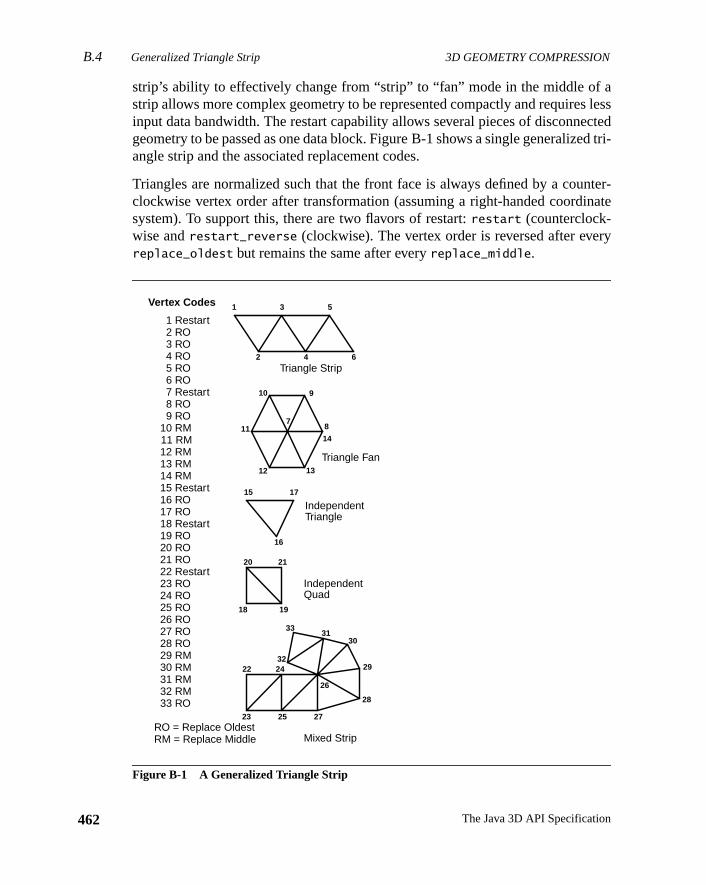
B.4 Generalized Triangle Strip 3D GEOMETRY COMPRESSION
462
lesscteded tri-
nter-nate
ry
strip’s ability to effectively change from “strip” to “fan” mode in the middle of astrip allows more complex geometry to be represented compactly and requiresinput data bandwidth. The restart capability allows several pieces of disconnegeometry to be passed as one data block. Figure B-1 shows a single generalizangle strip and the associated replacement codes.
Triangles are normalized such that the front face is always defined by a couclockwise vertex order after transformation (assuming a right-handed coordisystem). To support this, there are two flavors of restart:restart (counterclock-wise andrestart_reverse (clockwise). The vertex order is reversed after evereplace_oldest but remains the same after everyreplace_middle.
Figure B-1 A Generalized Triangle Strip
1
2
3
4
5
6
78
910
11
12 13
14
15
16
17
18 19
20
22
23
24
25
26
27
28
29
3031
32
33
21
1 Restart 2 RO 3 RO 4 RO 5 RO 6 RO 7 Restart 8 RO 9 RO10 RM11 RM12 RM13 RM14 RM15 Restart16 RO17 RO18 Restart19 RO20 RO21 RO22 Restart23 RO24 RO25 RO26 RO27 RO28 RO29 RM30 RM31 RM32 RM33 RO
Triangle Strip
Triangle Fan
IndependentTriangle
IndependentQuad
Mixed Strip
Vertex Codes
RO = Replace OldestRM = Replace Middle
The Java 3D API Specification
3D GEOMETRY COMPRESSION Generalized Triangle MeshB.5
cient-
act, thedataatang is
atry in
cesfer-ffer totice:truc-
prob-edreg-orageex.
ssedessedr by
. Six-eingepre-
B.5 Generalized Triangle Mesh
The first stage of compressed geometry is to convert triangle data into an effilinear strip form: thegeneralized triangle mesh. This is a near-optimal representation of triangle data, given fixed storage.
The existing concept of a generalized triangle strip structure allows for comprepresentation of geometry while maintaining a linear data structure. That isgeometry can be extracted by a single monotonic scan over the vertex arraystructure. This is very important for pipelined hardware implementations. A dformat that requires random access back to main memory during processiproblematic.
However, by confining itself to linear strips, the generalized triangle strip formleaves a potential factor of two (in space) on the table. Consider the geometFigure B-2.
While it can be represented by one triangle strip, many of the interior vertiappear twice in the strip. This is inherent in any approach wishing to avoid reences to old data. Some systems have tried using a simple regular mesh busupport reuse of old vertices, but there is a problem with this approach in pracIn general, geometry does not come in a perfectly regular rectangular mesh sture.
The generalized technique employed by compressed geometry addresses thislem. Old vertices areexplicitly pushed into a queue and then explicitly referencin the future when the old vertex is desired again. This fine control supports irular meshes of nearly any shape. Any viable technique must recognize that stis finite; thus, the maximum queue length is fixed at 16, requiring a four-bit indWe refer to this queue as themesh buffer. The combination of generalized trianglestrips and mesh buffer references is referred to as ageneralized triangle mesh.
The fixed mesh buffer size requires all tessellators or restripifiers for compregeometry to break up any runs longer than 16 unique references. Since comprgeometry is not meant to be programmed directly at the user level, but rathesophisticated tessellators or reformatters, this is not too onerous a restrictionteen old vertices allow up to 94 percent of the redundant geometry to avoid brespecified. Figure B-2 also contains an example of a general mesh buffer rsentation of the surface geometry.
463Version 1.2, April 2000
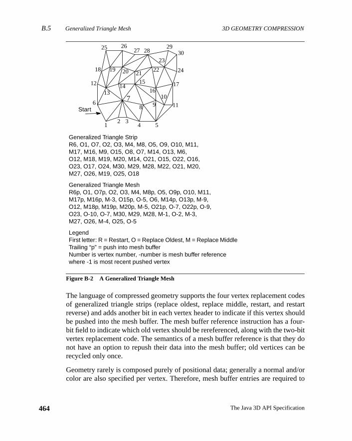
B.5 Generalized Triangle Mesh 3D GEOMETRY COMPRESSION
464
codesstartouldfour--bitey don be
d/ored to
Figure B-2 A Generalized Triangle Mesh
The language of compressed geometry supports the four vertex replacementof generalized triangle strips (replace oldest, replace middle, restart, and rereverse) and adds another bit in each vertex header to indicate if this vertex shbe pushed into the mesh buffer. The mesh buffer reference instruction has abit field to indicate which old vertex should be rereferenced, along with the twovertex replacement code. The semantics of a mesh buffer reference is that thnot have an option to repush their data into the mesh buffer; old vertices carecycled only once.
Geometry rarely is composed purely of positional data; generally a normal ancolor are also specified per vertex. Therefore, mesh buffer entries are requir
Generalized Triangle StripR6, O1, O7, O2, O3, M4, M8, O5, O9, O10, M11,M17, M16, M9, O15, O8, O7, M14, O13, M6,O12, M18, M19, M20, M14, O21, O15, O22, O16,O23, O17, O24, M30, M29, M28, M22, O21, M20,M27, O26, M19, O25, O18
Generalized Triangle MeshR6p, O1, O7p, O2, O3, M4, M8p, O5, O9p, O10, M11,M17p, M16p, M-3, O15p, O-5, O6, M14p, O13p, M-9,O12, M18p, M19p, M20p, M-5, O21p, O-7, O22p, O-9,O23, O-10, O-7, M30, M29, M28, M-1, O-2, M-3,M27, O26, M-4, O25, O-5
LegendFirst letter: R = Restart, O = Replace Oldest, M = Replace MiddleTrailing “p” = push into mesh bufferNumber is vertex number, -number is mesh buffer referencewhere -1 is most recent pushed vertex
Start
12 3
4
6
5
78 9
10
11
12
1314
15
1617
18 19 20 2122
23
24
25 2627 28
2930
The Java 3D API Specification
3D GEOMETRY COMPRESSION Position Representation and QuantizationB.6
ing
(per-si-
arersed.sh
tantis
tioned ford as
llythexpo-en-bitthedatat 16
peci-reacks,posi-
achlizedoneetry
contain storage for all associated per-vertex information (specifically includnormals, and colors.
For maximum space efficiency, when a vertex is specified in the data stream,vertex) normal and/or color information should be directly bundled with the potion information. This bundling is controlled by two state bits:bundle normals withvertices(bnv) andbundle colors with vertices(bcv). When a vertex is pushed intothe mesh buffer, these bits control whether its bundled normal and/or colorpushed as well. During a mesh buffer reference instruction, this process is reveThe two bits specify if a normal and/or color should be inherited from the mebuffer storage or inherited from thecurrent normal or current color.
There are explicit instructions for setting these two current values. An imporexception to this rule occurs when an explicit “set current normal” instructionfollowed by a mesh buffer reference, with thebnv state bit active. In this case,the former overrides the mesh buffer normal. This allows compact representaof hard edges in surface geometry. The analogous semantics are also defincolors, allowing compact representation of hard edges in images embeddegeometry.
B.6 Position Representation and Quantization
The 8-bit exponent of 32-bit IEEE floating-point numbers allows positions literato span the known universe: from a scale of 100 billion light years down toradius of subatomic particles. However, for any given tessellated object the enent is really specified just once by the current modeling matrix; within a givmodeling space, the object geometry is effectively described with only the 24fixed-point mantissa. Visually, in many cases far fewer bits are needed; thuslanguage of compressed geometry supports variable quantization of positiondown to as little as one bit. The maximum number of bits supported is at mosbits of precision per component of position.
We still assume that the position and scale of the local modeling spaces are sfied by full 32-bit or 64-bit floating-point coordinates. If sufficient numerical cais taken, several such modeling spaces can be stitched together without crforming seamless geometry coordinate systems with much greater than 16-bittional precision.
Most geometry is local, so within the 16-bit (or less) modeling space (of eobject), the delta difference between one vertex and the next in the generamesh buffer stream is very likely to be less than 16 bits in significance. Indeed,can histogram the bit length of neighboring position deltas in a batch of geom
465Version 1.2, April 2000
B.7 Color Representation and Quantization 3D GEOMETRY COMPRESSION
466
rticesizedding
elta
Bsignivityeterthat
spixel
also
pres-pres-cedsion
com-ion,thatssedd the
xelsity.po-
mpo-
it upf thisxed.ore
and, based on this histogram, assign a variable-length code to represent the vecompactly. The typical coding used in many other similar situations is customHuffman code; this is the case for compressed geometry. The details of the coof position deltas will be discussed later, in the context of color and normal dcoding.
B.7 Color Representation and Quantization
We treat colors similar to positions, but without using negative values. Thus RGαcolor data is first quantized to 15-bit unsigned fraction components, and a zerobit is added to form a 16-bit signed number. These are absolute linear reflectvalues, with 1.0 representing 100 percent reflectivity. An additional paramallows color data to be quantized effectively to any amount less than 16 bits;is, the colors can all be within a 5-5-5 RGB color space. (Theα field is optional,controlled by thecolor alpha present(cap) state bit.) Note that this decision doenot necessarily cause mach banding on the final rendered image; individualcolors are still interpolated between these quantized vertex colors, and verticesare subject to lighting.
The same delta coding used for color components is used for positions. Comsion of color data is where compressed geometry and traditional image comsion face the most similar problem. However, many of the more advantechniques for image compression were rejected for geometry color compresbecause of the difference in focus.
Image compression makes several assumptions about the viewing of the depressed data thatcannotbe made for compressed geometry. In image compressit is known a priori that the pixels appear in a perfect rectangular array, andwhen viewed, each pixel subtends a narrow range of visual angles. In compregeometry, one has almost no idea what the relationship between the viewer anrasterized geometry will be.
In image compression, it is known that the spatial frequency of the displayed pion the viewer’s eyes is likely higher than the human visual system’s color acuThis is why colors are usually converted to yuv space, so that the uv color comnents can be represented at a lower spatial frequency than the y (intensity) conent.
Usually the digital bits representing the subsampled uv components are splamong two or more pixels. Compressed geometry cannot take advantage obecause the display scale of the geometry relative to the viewer’s eye is not fiAlso, given that compressed triangle vertices are connected to four to eight or m
The Java 3D API Specification
3D GEOMETRY COMPRESSION Normal Representation and QuantizationB.8
aring
onalformsount
d ofEEnsi-
verynglesrs
the.en-
r-or-
f the
elyThe
vingmalcial
theat anuallytely
other vertices in the generalized triangle mesh, there is no consistent way of sh“half” the color information across vertices.
Similar arguments apply for the more sophisticated transforms used in traditiimage compression, such as the discrete cosine transform. These transassume a regular (rectangular) sampling of pixel values and require a large amof random access during decompression.
B.8 Normal Representation and Quantization
Probably the most innovative concept in compressed geometry is the methocompressing surface normals. Traditionally, 96-bit normals (three 32-bit IEfloating-point numbers) are used in calculations to determine 8-bit color inteties. Theoretically, 96 bits of information could be used to represent 296 differentnormals, spread evenly over the surface of a unit sphere. This is a normal e2–46 radians in any direction. Such angles are so exact that by spreading aout evenly in every direction from earth, you could point out any rock on Mawith subcentimeter accuracy.
But for normalized normals, the exponent bits are effectively unused. Givenconstraint |N| = 1, at least one ofNx, Ny, or Nz must be in the range of 0.5 to 1.0During rendering, this normal will be transformed by a composite modeling oritation matrixT: N' = N ⋅ T.
Assuming the typical implementation in which lighting is performed in world coodinates, the view transform is not involved in the processing of normals. If the nmals have been pre-normalized, then to avoid redundant renormalization onormals, the composite modeling transformation matrixT is typically pre-normal-ized to divide out any scale changes, and thus
T0,02 + T1,0
2 + T2,02 = 1, etc.
During the normal transformation, floating-point arithmetic hardware effectivtruncates all additive arguments to the accuracy of the largest component.result is that for a normalized normal being transformed by a scale-presermodeling orientation matrix, the numerical accuracy of the transformed norvalue is reduced to no more than 24-bit fixed-point accuracy in all but a few specases.
Even 24-bit normal components are still much higher in angular accuracy than(repaired) Hubble space telescope. After empirical tests, it was determined thangular density of 0.01 radians between normals gave results that were not visdistinguishable from finer representations. This works out to approxima
467Version 1.2, April 2000
B.8.1 Normals as Indices 3D GEOMETRY COMPRESSION
468
nor-po-
ly inese
bser-
l onee the
therf theoneowne
fold-
bits.
outble, the
thetions inouldcon-
oreityery
100,000 normals distributed over the unit sphere. In rectilinear space, thesemals still require high accuracy of representation; we chose to use 16-bit comnents that include one sign and one guard bit.
This still requires 48 bits to represent a normal. But since we are interested on100,000 specific normals, in theory a single 17-bit index could denote any of thnormals. The next section shows how it is possible to take advantage of this ovation.
B.8.1 Normals as Indices
The most obvious hardware implementation for converting an index of a normathe unit sphere back into anNx Ny Nz value is by table look-up. The problem is thsize of the table. Fortunately, several symmetry tricks can be applied to reducsize of the table greatly (by a factor of 48).
First, the unit sphere is symmetrical in the eight quadrants by sign bits. In owords, if we let three of the normal representation bits be the three sign bits oXYZ components of the normal, then we need only to find a way to representeighth of the unit sphere. The all positive sign bit octant of the unit sphere is shin bold outline on the left half of Figure B-3. This 000 sign bit octant will breferred to as theprime octant.
Second, each octant of the unit sphere can be split into six identical pieces bying about the planesX = Y, X = Z, andY= Z. Such a division of the prime octant isshown in Figure B-3. The six possible sextants are encoded with another threeNow only 1/48 of the sphere remains to be represented.
This reduces the 100,000-entry look-up table by a factor of 48, requiring only ab2,000 entries, small enough to fit into an on-chip ROM look-up table. This taneeds 11 address bits to index into it, so including our previous two 3-bit fieldsresult is a grand total of 17 bits for all three normal components.
Representing a finite set of unit normals is equivalent to positioning points onsurface of the unit sphere. While no perfectly equal angular density distribuexists for large numbers of points, many near-optimal distributions exist. Thutheory one of these with the same sort of 48-way symmetry described earlier cbe used for the decompression look-up table. However, several additionalstraints mandate a different choice of encoding:
• We desire a scalable density distribution in which zeroing more and mof the low-order address bits to the table still results in fairly even densof normals on the unit sphere. Otherwise a different look-up table for evencoding density would be required.
The Java 3D API Specification
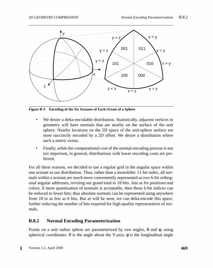
3D GEOMETRY COMPRESSION Normal Encoding ParameterizationB.8.2
s innitare
ere
notre-
ithinnor-hog-s andcan
whereace,or-
Figure B-3 Encoding of the Six Sextants of Each Octant of a Sphere
• We desire a delta-encodable distribution. Statistically, adjacent verticegeometry will have normals that are nearby on the surface of the usphere. Nearby locations on the 2D space of the unit-sphere surfacemost succinctly encoded by a 2D offset. We desire a distribution whsuch a metric exists.
• Finally, while the computational cost of the normal encoding process istoo important, in general, distributions with lower encoding costs are pferred.
For all these reasons, we decided to use a regular grid in the angular space wone sextant as our distribution. Thus, rather than a monolithic 11-bit index, allmals within a sextant are much more conveniently represented as two 6-bit ortonal angular addresses, revising our grand total to 18 bits. Just as for positioncolors, if more quantization of normals is acceptable, then these 6-bit indicesbe reduced to fewer bits; thus absolute normals can be represented using anyfrom 18 to as few as 6 bits. But as will be seen, we can delta-encode this spfurther reducing the number of bits required for high-quality representation of nmals.
B.8.2 Normal Encoding Parameterization
Points on a unit radius sphere are parameterized by two angles,θ and φ, usingspherical coordinates.θ is the angle about the Y-axis;φ is the longitudinal angle
y
z
y > z
y = z
y < z
x
z < z x = z x > z
x < y
x = y
x > y
001
101
100 000
010
011
469Version 1.2, April 2000
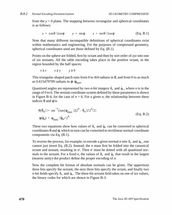
B.8.2 Normal Encoding Parameterization 3D GEOMETRY COMPRESSION
470
ates
xistetry,
the
howne
ricalte
l-st
osttwoes,
from they = 0 plane. The mapping between rectangular and spherical coordinis as follows:
(Eq. B.1)
Note that many different incompatible definitions of spherical coordinates ewithin mathematics and engineering. For the purposes of compressed geomspherical coordinates used are those defined by Eq. (B.1).
Points on the sphere are folded, first by octant and then by sort order ofxyzinto oneof six sextants. All the table encoding takes place in the positive octant, inregion bounded by the half spaces:
This triangular-shaped patch runs from 0 toπ/4 radians inθ, and from 0 to as muchas 0.615479709 radians inφ: φmax.
Quantized angles are represented by twon-bit integers and , wheren is in therange of 0 to 6. The sextant coordinate system defined by these parameters is sin Figure B-4, for the case ofn = 6. For a givenn, the relationship between thesindicesθ andφ is
(Eq. B.2)
These two equations show how values of and can be converted to sphecoordinatesθ andφ, which in turn can be converted to rectilinear normal coordinacomponents via Eq. (B.1).
To reverse the process, for example, to encode a given normaln into and , onecannot just invert Eq. (B.2). Instead, then must first be folded into the canonicaoctant and sextant, resulting inn'. Thenn' must be dotted with all quantized normals in the sextant. For a fixedn, the values of and that result in the large(nearest unity) dot product define the proper encoding ofn.
Now the complete bit format of absolute normals can be given. The uppermthree bits specify the sextant, the next three bits specify the octant, and finallyn-bit fields specify and . The three-bit sextant field takes on one of six valuthe binary codes for which are shown in Figure B-3.
x θcos φcos⋅= y φsin= z θsin φcos⋅=
x z≥ z y≥ y 0≥
θ̂n φ̂n
φ φ̂n( ) φmax φ̂n 2n⁄⋅=
θ θ̂n( ) sin1– φmax 2
n θ̂n–( ) 2n⁄⋅( )tan( )=
θ̂n φ̂n
θ̂n φ̂n
θ̂n φ̂n
θ̂n φ̂n
The Java 3D API Specification
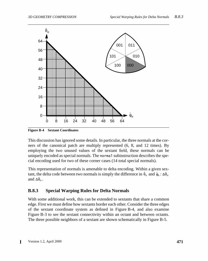
3D GEOMETRY COMPRESSION Special Warping Rules for Delta NormalsB.8.3
cor-. Byn be-
sex-
monedgesmineants.B-5.
Figure B-4 Sextant Coordinates
This discussion has ignored some details. In particular, the three normals at theners of the canonical patch are multiply represented (6, 8, and 12 times)employing the two unused values of the sextant field, these normals cauniquely encoded as special normals. Thenormal subinstruction describes the special encoding used for two of these corner cases (14 total special normals).
This representation of normals is amenable to delta encoding. Within a giventant, the delta code between two normals is simply the difference in and :and .
B.8.3 Special Warping Rules for Delta Normals
With some additional work, this can be extended to sextants that share a comedge. First we must define how sextants border each other. Consider the threeof the sextant coordinate system as defined in Figure B-4, and also exaFigure B-3 to see the sextant connectivity within an octant and between octThe three possible neighbors of a sextant are shown schematically in Figure
001
101
011
010
000100
56
64
32
48
40
24
16
8
00 8 16 24 32 40 48 56 64
φ̂n
θ̂n
θ̂n φ̂n ∆θ̂n
∆θ̂n
471Version 1.2, April 2000
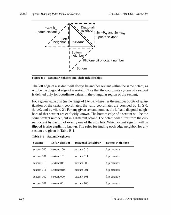
B.8.3 Special Warping Rules for Delta Normals 3D GEOMETRY COMPRESSION
472
t, asxtant
h-ther-
beny
Figure B-5 Sextant Neighbors and Their Relationships
The left edge of a sextant will always be another sextant within the same octanwill be the diagonal edge of a sextant. Note that the coordinate system of a seis defined only for coordinate values in the triangular region of the sextant.
For a given value ofn (in the range of 1 to 6), wheren is the number of bits of quan-tization of the sextant coordinates, the valid coordinates are bounded by≥ 0,
≥ 0, and + ≤ 2n. For any given sextant number, the left and diagonal neigbors of that sextant are explicitly known. The bottom edge of a sextant will besamesextant number, but in a different octant. The octant will differ from the curent octant by the flip of exactly one of the sign bits. Which octant sign bit willflipped is also explicitly known. The rules for finding each edge neighbor for asextant are given in Table B-1.
Table B-1 Sextant Neighbors
Sextant Left Neighbor Diagonal Neighbor Bottom Neighbor
sextant 000 sextant 100 sextant 010 flip octant y
sextant 001 sextant 101 sextant 011 flip octant x
sextant 010 sextant 011 sextant 000 flip octant z
sextant 011 sextant 010 sextant 001 flip octant z
sextant 100 sextant 000 sextant 101 flip octant y
sextant 101 sextant 001 sextant 100 flip octant x
Flip one bit of octant number
2n – and 2n –θ̂n φ̂nupdate sextant
Bottom
Bottomneighbor
Leftneighbor Sextant
Diagonalneighbor
Invert θ̂nupdate sextant
θ̂n
φ̂n θ̂n φ̂n
The Java 3D API Specification
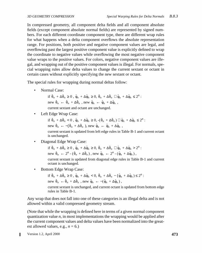
3D GEOMETRY COMPRESSION Special Warping Rules for Delta NormalsB.8.3
olutenum-rulestation, andrapnentille-
spe-nt in
tant
rent
edge
not
enttergreat-
In compressed geometry, all component delta fields and all component absfields (except component absolute normal fields) are represented by signedbers. For each different coordinate component type, there are different wrapfor what happens when a delta component overflows the absolute represenrange. For positions, both positive and negative component values are legaloverflowing past the largest positive component value is explicitly defined to wthe coordinate to negative values while overflowing the most negative compovalue wraps to the positive values. For colors, negative component values aregal, and wrapping out of the positive component values is illegal. For normals,cial wrapping rules allow delta values to change the current sextant or octacertain cases without explicitly specifying the new sextant or octant.
The special rules for wrapping during normal deltas follow:
• Normal Case:
if + ≥ 0 , + ≥ 0, + + + ≤ 2n :
new ← + , new ← + ,
current sextant and octant are unchanged.
• Left Edge Wrap Case:
if + < 0 , + ≥ 0, -( + )+ + ≤ 2n :
new ← −( + ), new ← + ,
current sextant is updated from left edge rules in Table B-1 and current ocis unchanged.
• Diagonal Edge Wrap Case:
if + ≥ 0 , + ≥ 0, + + + > 2n :
new ← 2n - ( + ) , new ← 2n - ( + ) ,
current sextant is updated from diagonal edge rules in Table B-1 and curoctant is unchanged.
• Bottom Edge Wrap Case:
if + ≥ 0 , + < 0, + − ( + ) ≤ 2n :
new ← + , new ← −( + ) ,
current sextant is unchanged, and current octant is updated from bottomrules in Table B-1.
Any wrap that does not fall into one of these categories is an illegal delta and isallowed within a valid compressed geometry stream.
(Note that while the wrapping is defined here in terms of a given normal componquantization valuen, in most implementations the wrapping would be applied afthe current component values and delta values have been normalized into theest allowed values, e.g.,n = 6.)
θ̂n ∆θ̂n φ̂n ∆φ̂n θ̂n ∆θ̂n φ̂n ∆φ̂n
θ̂n θ̂n ∆θ̂n φ̂n φ̂n ∆φ̂n
θ̂n ∆θ̂n φ̂n ∆φ̂n θ̂n ∆θ̂n φ̂n ∆φ̂n
θ̂n θ̂n ∆θ̂n φ̂n φ̂n ∆φ̂n
θ̂n ∆θ̂n φ̂n ∆φ̂n θ̂n ∆θ̂n φ̂n ∆φ̂n
θ̂n θ̂n ∆θ̂n φ̂n φ̂n ∆φ̂n
θ̂n ∆θ̂n φ̂n ∆φ̂n θ̂n ∆θ̂n φ̂n ∆φ̂n
θ̂n θ̂n ∆θ̂n φ̂n φ̂n ∆φ̂n
473Version 1.2, April 2000
B.9 Modified Huffman Encoding 3D GEOMETRY COMPRESSION
474
bitional
nted,roms toming
gs toyp-elf-y a
posi-ata>set)to as
el; forow-and
is
indi-
e thaty not
ss all
-
B.9 Modified Huffman Encoding
There are many techniques known for minimally representing variable-lengthfields. For compressed geometry, we have chosen a variation of the conventHuffman technique.
The Huffman compression algorithm takes in a set of symbols to be represealong with frequency of occurrence statistics (histograms) of those symbols. Fthis, variable-length, uniquely identifiable bit patterns that allow these symbolbe represented with a near-minimum total number of bits are generated, assuthat symbols do occur at the frequencies specified.
Many compression techniques, including JPEG, create unique symbols as taindicate the length of a variable-length data field that follows. This data field is tically a specific-length delta value. Thus the final binary stream consists of (sdescribing length) variable-length tag symbols, each immediately followed bdata field whose length is associated with that unique tag symbol.
The binary format for compressed geometry uses this technique to representtion, normal, and color data fields. For compressed geometry, these <tag, dfields are immediately preceded by (a more conventional computer instructionopcode field. These fields, plus potential additional operand bits, are referredgeometry instructions (see Figure B-6).
Traditionally, each value to be compressed is assigned its own associated labexample, anxyzdelta position would be represented by three tag/value pairs. Hever, the deltaxyzvalues are not uncorrelated, and we can get both a densersimpler representation by taking advantage of this fact.
In general, thexyzdeltas statistically point equally in all directions in space. Thmeans that if the number of bits to represent the largest of these deltas isn, thenstatistically the other two delta values require an average ofn – 1.4 bits for theirrepresentation. Thus we made the decision to use a single field-length tag tocate the bit length of∆x, ∆y, and∆z.
This also means that we cannot take advantage of another Huffman techniqusaves somewhat less than one more bit per component, but our bit savings bhaving to specify two additional tag fields (for∆y and∆z) outweigh this. A singletag field also means that a hardware decompression engine can decomprethree fields in parallel, if desired.
Similar arguments hold for deltas of RGBα values, and so here also a single fieldlength tag indicates the bit-length of the∆R, ∆G, ∆B, and∆α (if present) fields.
The Java 3D API Specification
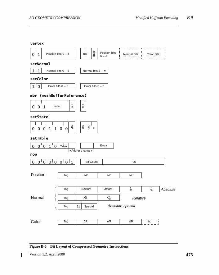
3D GEOMETRY COMPRESSION Modified Huffman Encoding B.9
Figure B-6 Bit Layout of Compressed Geometry Instructions
0
vertex
setNormal
setColor
mbr (meshBufferReference)
setState
setTable
nop
Position
Normal
Color
Position bits 0 – 5
Normal bits 0 – 5
Color bits 0 – 5
Position bits6 – n
Normal bits Color bits
Normal bits 6 – n
Color bits 6 – n
repIndex rep
bnv
bcv
cap
TableAddress range
Entry
Bit Count 0s
Tag
Tag
∆X ∆Y ∆Z
∆R ∆G ∆B ∆α
0 0 0 0 0 0 0 1
0 0 0 1 0
0 0 0 1 1 0 0
0 0 1
1 0
1 1
0 1 rep
mbp
Tag
Tag
Tag
Sextant Octant θt^ φt
^
∆θt^ ∆φt
^
Special11
Absolute
Relative
Absolute special
475Version 1.2, April 2000
B.10 Compressed Geometry Instructions 3D GEOMETRY COMPRESSION
476
me-
uenta-le.)s con-tion
entrylativeeral,
ple-ight-thecessream
-cases
ed inriefese
sionfixed
Theu v index fields of both absolute normals and delta normals are also paraterized by a single value (n), which can be specified by a single tag.
We chose to limit the length of the Huffman tag field to the relatively small valof six bits. This was done to facilitate high-speed, low-cost hardware implemetions. (A 64-entry tag look-up table allows decoding of tags in one clock cycThree such tables exist: one each for positions, normals, and colors. The tabletain the length of the tag field, the length of the data field(s), a data normalizacoefficient (the up-shift), and an absolute/relative bit.
The tag field can be 0 to 6 bits in length. Zero-length tags are used when everyin the table is identical: same data length, same up-shift, and same absolute/rebit. The tag becomes irrelevant because there is nothing to differentiate. In genthere are only a few specialized cases where zero-length tags are useful.
One additional complication was required to enable reasonable hardware immentations. As seen in a later section, all instructions are broken up into an ebit header and a variable-length body. Sufficient information to determinelength of the body is present in the header. But to give the hardware time to prothe header information, the header of one instruction must be placed in the stbefore the body of the previous instruction. Thus the sequence… B0 H1B1 H2B2H3 has to be encoded as follows:
H1 B0 H2 B1 H3 B2
Thisheader forwardingis applied to all instructions. The vertex instruction optionally had one or two subfields that need forwarded headers. In these specialthe headers are only six bits in length, because no opcode is present.
B.10 Compressed Geometry Instructions
Java 3D’s compressed geometry protocol defines seven instructions to be usspecifying 3D geometry and certain affiliated attributes. Table B-2 gives a boverview of these instructions and some of their semantics. More detail of thinstructions, including their bit layout, is given in the following sections.
B.11 Bit Layout of Compressed Geometry Instructions
Figure B-6 shows the bit-level layout of the seven geometry decompresinstructions. Each instruction has a unique opcode and then some (usuallynumber of) arguments. In the case of thesetColor instruction, the number of argu-ments can be either three or four, depending on the current setting of thecap bit
…
… …
The Java 3D API Specification
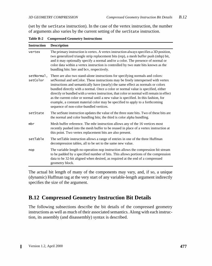
3D GEOMETRY COMPRESSION Compressed Geometry Instruction Bit DetailsB.12
er
quectly
etrytruc-
n,bit,r
tex
t
are
n at
amion
(set by thesetState instruction). In the case of the vertex instruction, the numbof arguments also varies by the current setting of thesetState instruction.
The actual bit length of many of the components may vary, and, if so, a uni(dynamic) Huffman tag at the very start of any variable-length argument indirespecifies the size of the argument.
B.12 Compressed Geometry Instruction Bit Details
The following subsections describe the bit details of the compressed geominstructions as well as much of their associated semantics. Along with each instion, its assembly (and disassembly) syntax is described.
Table B-2 Compressed Geometry Instructions
Instruction Description
vertex The primary instruction is vertex. A vertex instruction always specifies a 3D positiotwo generalized triangle strip replacement bits (rep), a mesh buffer push (mbp) and it may optionally specify a normal and/or a color. The presence of normal ocolor data within a vertex instruction is controlled by two state bits known as thebundling bits: bnv and bcv, respectively.
setNormal,setColor
There are also two stand-alone instructions for specifying normals and colors:setNormal and setColor. These instructions may be freely interspersed with verinstructions and semantically have (nearly) the same effect as normals or colorsbundled directly with a normal. Once a color or normal value is specified, eitherdirectly or bundled with a vertex instruction, that color or normal will remain in effecas the current color or normal until a new value is specified. In this fashion, forexample, a constant material color may be specified to apply to a forthcomingsequence of non-color-bundled vertices.
setState The setState instruction updates the value of the three state bits. Two of these bitsthe normal and color bundling bits; the third is color alpha bundling.
mbr Mesh buffer reference. The mbr instruction allows any of the 16 vertices mostrecently pushed into the mesh buffer to be reused in place of a vertex instructiothis point. Two vertex replacement bits are also present.
setTable The setTable instruction allows a range of entries in one of the three Huffmandecompression tables, all to be set to the same new value.
nop The variable length no-operation nop instruction allows the compression bit streto be padded by a specified number of bits. This allows portions of the compressdata to be 32-bit aligned when desired, as required at the end of a compressedgeometry block.
477Version 1.2, April 2000
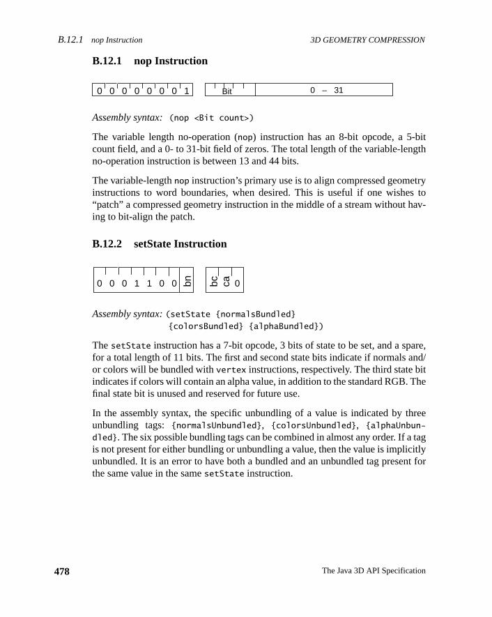
B.12.1 nop Instruction 3D GEOMETRY COMPRESSION
478
itgth
trys toav-
are,nd/
ithe
ree
tagitlynt for
B.12.1 nop Instruction
Assembly syntax:(nop <Bit count>)
The variable length no-operation (nop) instruction has an 8-bit opcode, a 5-bcount field, and a 0- to 31-bit field of zeros. The total length of the variable-lenno-operation instruction is between 13 and 44 bits.
The variable-lengthnop instruction’s primary use is to align compressed geomeinstructions to word boundaries, when desired. This is useful if one wishe“patch” a compressed geometry instruction in the middle of a stream without hing to bit-align the patch.
B.12.2 setState Instruction
Assembly syntax:(setState {normalsBundled}{colorsBundled} {alphaBundled})
ThesetState instruction has a 7-bit opcode, 3 bits of state to be set, and a spfor a total length of 11 bits. The first and second state bits indicate if normals aor colors will be bundled withvertex instructions, respectively. The third state bindicates if colors will contain an alpha value, in addition to the standard RGB. Tfinal state bit is unused and reserved for future use.
In the assembly syntax, the specific unbundling of a value is indicated by thunbundling tags:{normalsUnbundled}, {colorsUnbundled}, {alphaUnbun-
dled}. The six possible bundling tags can be combined in almost any order. If ais not present for either bundling or unbundling a value, then the value is implicunbundled. It is an error to have both a bundled and an unbundled tag presethe same value in the samesetState instruction.
0 – 31Bit0 0 0 0 0 0 0 1
bc0 0 0 1 1 0 0 bn ca 0
The Java 3D API Specification
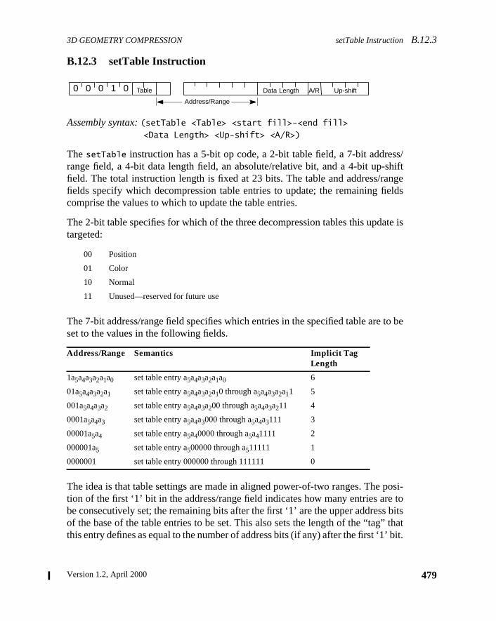
3D GEOMETRY COMPRESSION setTable InstructionB.12.3
ss/hiftngeelds
te is
to be
posi-e to
bitsthat
’ bit.
B.12.3 setTable Instruction
Assembly syntax:(setTable <Table> <start fill>-<end fill><Data Length> <Up-shift> <A/R>)
ThesetTable instruction has a 5-bit op code, a 2-bit table field, a 7-bit addrerange field, a 4-bit data length field, an absolute/relative bit, and a 4-bit up-sfield. The total instruction length is fixed at 23 bits. The table and address/rafields specify which decompression table entries to update; the remaining ficomprise the values to which to update the table entries.
The 2-bit table specifies for which of the three decompression tables this updatargeted:
The 7-bit address/range field specifies which entries in the specified table areset to the values in the following fields.
The idea is that table settings are made in aligned power-of-two ranges. Thetion of the first ‘1’ bit in the address/range field indicates how many entries arbe consecutively set; the remaining bits after the first ‘1’ are the upper addressof the base of the table entries to be set. This also sets the length of the “tag”this entry defines as equal to the number of address bits (if any) after the first ‘1
00 Position
01 Color
10 Normal
11 Unused—reserved for future use
Address/Range Semantics Implicit TagLength
1a5a4a3a2a1a0 set table entry a5a4a3a2a1a0 6
01a5a4a3a2a1 set table entry a5a4a3a2a10 through a5a4a3a2a11 5
001a5a4a3a2 set table entry a5a4a3a200 through a5a4a3a211 4
0001a5a4a3 set table entry a5a4a3000 through a5a4a3111 3
00001a5a4 set table entry a5a40000 through a5a41111 2
000001a5 set table entry a500000 through a511111 1
0000001 set table entry 000000 through 111111 0
Table
Address/Range
Data Length0 0 0 1 0 Up-shiftA/R
479Version 1.2, April 2000
B.12.4 mbr (meshBufferReference) Instruction 3D GEOMETRY COMPRESSION
480
is tagf the
deltahers theo 15ctual
mals,ly 7.sed.
tagsl fore dataatar ofys
gth.
mingf 12its inup-
thaticatesncestant.
The data length specifies how large the delta values to be associated with thare; a data length of 12 implies that the upper 4 bits are to be sign extensions oincoming delta value. Note that the data length describes not the length of thevalue coming in, but the final position of the delta value for reconstruction. In otwords, the data length field is the sum of the actual delta bits to be read in pluup-shift amount. For the position and color tables, the data length values of 1 tcorrespond to lengths of 1 to 15, but the data length value of 0 encodes an alength of 16, as a length of 0 makes no sense for positions and colors. For nora length of 0 is sometimes appropriate, and the maximum length needed is onThus for normals, the values 0 to 7 map through 0 to 7, and 8 to 15 are not u
The up-shift value is the number of bits that the delta values described by thesewill be shifted up before being added to the current value. The up-shift is usefuquantizing the data to save space; it cannot be used to extend the range of threpresented. You are still limited to 16 bits (less for normals) for the resultant deven with a large up-shift value. The up-shift amount is essentially the numbelow bits that you don’t need to specify in the incoming data since they will alwabe zero. It is illegal for the up-shift to be greater than or equal to the data len
So, there are three portions of the resultant data: the sign extension, the incodata, and the up-shift. For example, if you have a position with a data length oand an up-shift of 4, then the resultant data is made up of 4 sign extension bthe high bits, 8 bits of incoming data, and 4 bits of zero in the low bits, for theshift.
The absolute/relative flag indicates whether this table entry describes valuesare to be interpreted as an absolute reference or a relative delta—a 0 value indrelative, a 1 value indicates absolute. Note that for normals, absolute referewill have an additional six leading bits that describe the absolute octant and sex
B.12.4 mbr (meshBufferReference) Instruction
Assembly syntax:(mbr <rep> <index>)
Assembly syntax:<rep>:
RST Restart
RSTR Restart reverse
RMID Replace middle
ROLD Replace oldest
repIndex rep0 0 1
The Java 3D API Specification
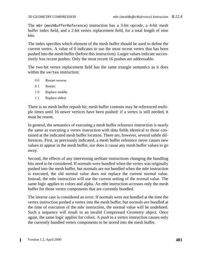
3D GEOMETRY COMPRESSION mbr (meshBufferReference) InstructionB.12.4
hine
e thebeences-
does
ulti-d, it
earlycon-e dif-s newto go
dlingnally
.Themesh
ed.nce
The mbr (meshBufferReference) instruction has a 3-bit opcode, a 4-bit mesbuffer index field, and a 2-bit vertex replacement field, for a total length of nbits.
The index specifies which element of the mesh buffer should be used to defincurrent vertex. A value of 0 indicates to use the most recent vertex that haspushed into the mesh buffer (before this instruction). Larger values indicate sucsively less recent pushes. Only the most recent 16 pushes are addressable.
The two-bit vertex replacement field has the same triangle semantics as itwithin thevertex instruction:
There is no mesh buffer repush bit; mesh buffer contents may be referenced mple times until 16 newer vertices have been pushed: if a vertex is still needemust be resent.
In general, the semantics of executing a mesh buffer reference instruction is nthe same as executing a vertex instruction with data fields identical to thosetained at the indicated mesh buffer location. There are, however, several subtlferences. First, as previously indicated, a mesh buffer reference never causevalues to appear in the mesh buffer, nor does it cause any mesh buffer valuesaway.
Second, the effects of any intervening setState instructions changing the bunbits need to be considered. If normals were bundled when the vertex was origipushed into the mesh buffer, but normals arenotbundled when the mbr instructionis executed, the old normal valuedoes notreplace the current normal valueInstead, the mbr instruction will use the current setting of the normal value.same logic applies to colors and alpha. An mbr instruction accesses only thebuffer for those vertex components that are currently bundled.
The inverse case is considered an error: If normals werenotbundled at the time thevertex instruction pushed a vertex into the mesh buffer, but normalsarebundled atthe time of execution of the mbr instruction, the normal value will be undefinSuch a sequence will result in an invalid Compressed Geometry object. Oagain, the same logic applies for colors. Apushin a vertex instruction causes onlythe currently bundled vertex components to be stored into the mesh buffer.
0 0 Restart reverse
0 1 Restart
1 0 Replace middle
1 1 Replace oldest
481Version 1.2, April 2000
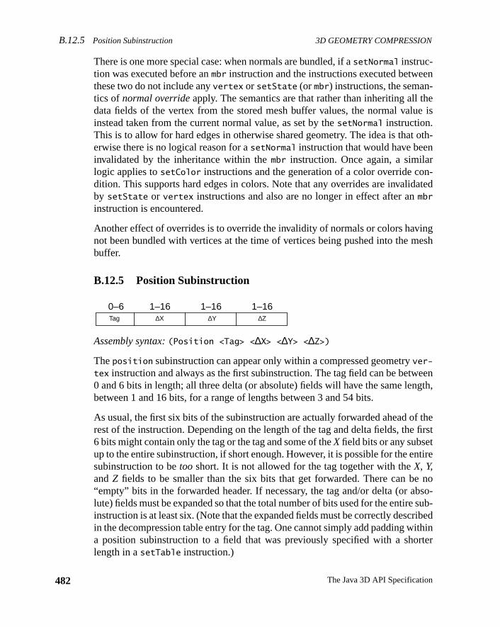
B.12.5 Position Subinstruction 3D GEOMETRY COMPRESSION
482
en
hee is
oth-
n-ated
ngesh
eength,
f thefirst
tire
nobso-sub-
ribedithinrter
There is one more special case: when normals are bundled, if asetNormal instruc-tion was executed before anmbr instruction and the instructions executed betwethese two do not include anyvertex or setState (or mbr) instructions, the seman-tics of normal overrideapply. The semantics are that rather than inheriting all tdata fields of the vertex from the stored mesh buffer values, the normal valuinstead taken from the current normal value, as set by thesetNormal instruction.This is to allow for hard edges in otherwise shared geometry. The idea is thaterwise there is no logical reason for asetNormal instruction that would have beeninvalidated by the inheritance within thembr instruction. Once again, a similarlogic applies tosetColor instructions and the generation of a color override codition. This supports hard edges in colors. Note that any overrides are invalidby setState or vertex instructions and also are no longer in effect after anmbr
instruction is encountered.
Another effect of overrides is to override the invalidity of normals or colors havinot been bundled with vertices at the time of vertices being pushed into the mbuffer.
B.12.5 Position Subinstruction
Assembly syntax:(Position <Tag> <∆X> <∆Y> <∆Z>)
Theposition subinstruction can appear only within a compressed geometryver-
tex instruction and always as the first subinstruction. The tag field can be betw0 and 6 bits in length; all three delta (or absolute) fields will have the same lenbetween 1 and 16 bits, for a range of lengths between 3 and 54 bits.
As usual, the first six bits of the subinstruction are actually forwarded ahead orest of the instruction. Depending on the length of the tag and delta fields, the6 bits might contain only the tag or the tag and some of theX field bits or any subsetup to the entire subinstruction, if short enough. However, it is possible for the ensubinstruction to betoo short. It is not allowed for the tag together with theX, Y,andZ fields to be smaller than the six bits that get forwarded. There can be“empty” bits in the forwarded header. If necessary, the tag and/or delta (or alute) fields must be expanded so that the total number of bits used for the entireinstruction is at least six. (Note that the expanded fields must be correctly descin the decompression table entry for the tag. One cannot simply add padding wa position subinstruction to a field that was previously specified with a sholength in asetTable instruction.)
Tag ∆X ∆Y ∆Z
0–6 1–16 1–16 1–16
The Java 3D API Specification
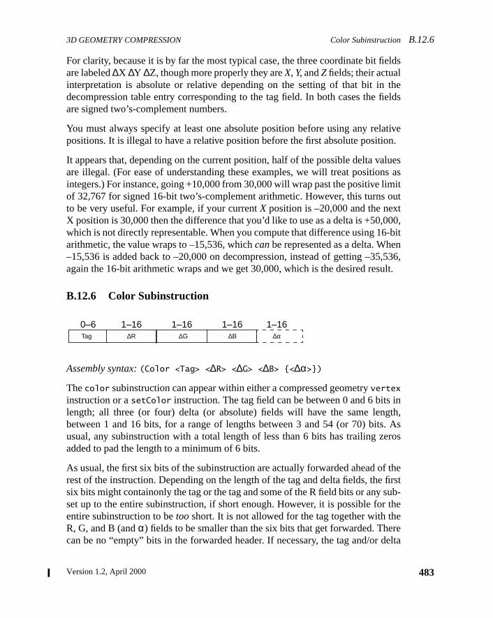
3D GEOMETRY COMPRESSION Color SubinstructionB.12.6
elds
thefields
ativeon.
luess as
imitoutt00,-bitn,536,ult.
inth,. Asros
f thefirstub-the
ereelta
For clarity, because it is by far the most typical case, the three coordinate bit fiare labeled∆X ∆Y ∆Z, though more properly they areX, Y, andZ fields; their actualinterpretation is absolute or relative depending on the setting of that bit indecompression table entry corresponding to the tag field. In both cases theare signed two’s-complement numbers.
You must always specify at least one absolute position before using any relpositions. It is illegal to have a relative position before the first absolute positi
It appears that, depending on the current position, half of the possible delta vaare illegal. (For ease of understanding these examples, we will treat positionintegers.) For instance, going +10,000 from 30,000 will wrap past the positive lof 32,767 for signed 16-bit two’s-complement arithmetic. However, this turnsto be very useful. For example, if your currentX position is –20,000 and the nexX position is 30,000 then the difference that you’d like to use as a delta is +50,0which is not directly representable. When you compute that difference using 16arithmetic, the value wraps to –15,536, whichcanbe represented as a delta. Whe–15,536 is added back to –20,000 on decompression, instead of getting –35again the 16-bit arithmetic wraps and we get 30,000, which is the desired res
B.12.6 Color Subinstruction
Assembly syntax:(Color <Tag> <∆R> <∆G> <∆B> {<∆α>})
Thecolor subinstruction can appear within either a compressed geometryvertex
instruction or asetColor instruction. The tag field can be between 0 and 6 bitslength; all three (or four) delta (or absolute) fields will have the same lengbetween 1 and 16 bits, for a range of lengths between 3 and 54 (or 70) bitsusual, any subinstruction with a total length of less than 6 bits has trailing zeadded to pad the length to a minimum of 6 bits.
As usual, the first six bits of the subinstruction are actually forwarded ahead orest of the instruction. Depending on the length of the tag and delta fields, thesix bits might containonly the tag or the tag and some of the R field bits or any sset up to the entire subinstruction, if short enough. However, it is possible forentire subinstruction to betoo short. It is not allowed for the tag together with thR, G, and B (andα) fields to be smaller than the six bits that get forwarded. Thecan be no “empty” bits in the forwarded header. If necessary, the tag and/or d
Tag ∆R ∆G ∆B
0–6 1–16 1–16 1–16∆α
1–16
483Version 1.2, April 2000
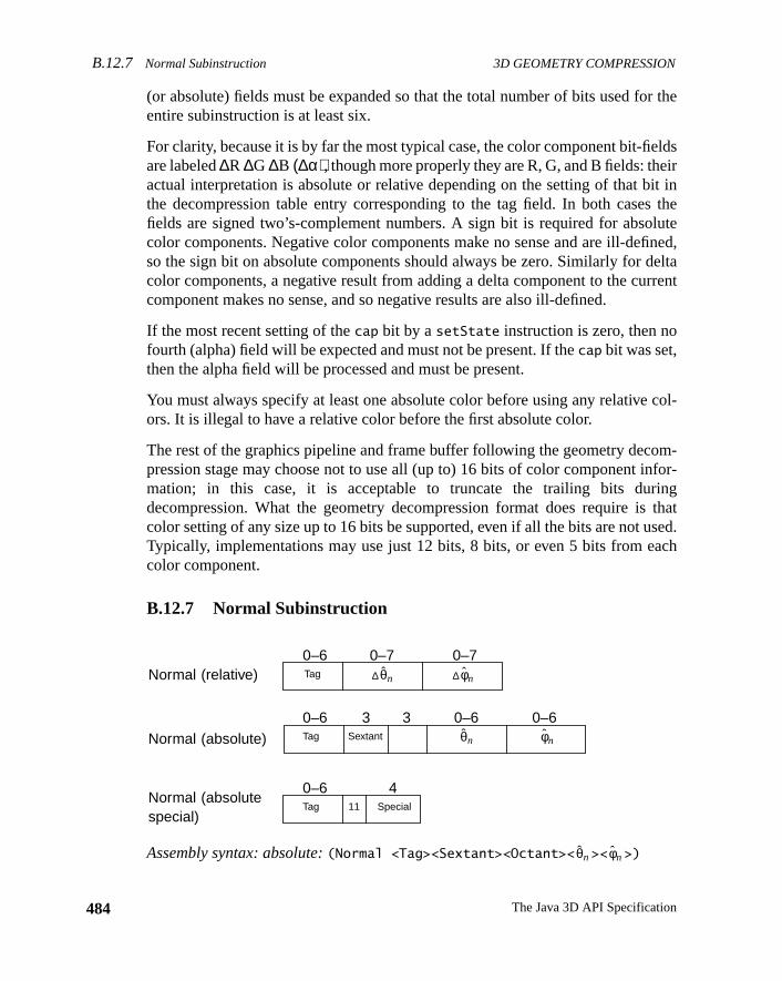
B.12.7 Normal Subinstruction 3D GEOMETRY COMPRESSION
484
r the
eldsirit ins thelutefined,eltarrent
col-
om-for-
ingthat
sed.ach
(or absolute) fields must be expanded so that the total number of bits used foentire subinstruction is at least six.
For clarity, because it is by far the most typical case, the color component bit-fiare labeled∆R ∆G ∆B (∆α), though more properly they are R, G, and B fields: theactual interpretation is absolute or relative depending on the setting of that bthe decompression table entry corresponding to the tag field. In both casefields are signed two’s-complement numbers. A sign bit is required for absocolor components. Negative color components make no sense and are ill-deso the sign bit on absolute components should always be zero. Similarly for dcolor components, a negative result from adding a delta component to the cucomponent makes no sense, and so negative results are also ill-defined.
If the most recent setting of thecap bit by asetState instruction is zero, then nofourth (alpha) field will be expected and must not be present. If thecap bit was set,then the alpha field will be processed and must be present.
You must always specify at least one absolute color before using any relativeors. It is illegal to have a relative color before the first absolute color.
The rest of the graphics pipeline and frame buffer following the geometry decpression stage may choose not to use all (up to) 16 bits of color component inmation; in this case, it is acceptable to truncate the trailing bits durdecompression. What the geometry decompression format does require iscolor setting of any size up to 16 bits be supported, even if all the bits are not uTypically, implementations may use just 12 bits, 8 bits, or even 5 bits from ecolor component.
B.12.7 Normal Subinstruction
Assembly syntax: absolute:(Normal <Tag><Sextant><Octant>< >< >)
Normal (relative) Tag ∆ θ̂n
0–6 0–7
Normal (absolute)
Normal (absolutespecial)
Tag
0–6
Tag
0–6
∆ φ̂n
θ̂n φ̂n
0–7
0–6 0–63 3Sextant
Special11
4
θ̂n φ̂n
The Java 3D API Specification
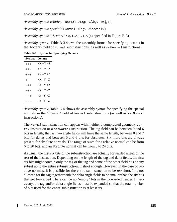
3D GEOMETRY COMPRESSION Normal SubinstructionB.12.7
in
ial
6nd 7ays
from
f thefirstanyf rel-
bitsec-mber
Assembly syntax: relative:(Normal <Tag> <∆ > <∆ >)
Assembly syntax: special:(Normal <Tag> <Special>)
Assembly syntax: <Sextant>:0,1,2,3,4,5 (as specified in Figure B-3)
Assembly syntax:Table B-3 shows the assembly format for specifying octantsthe <octant> field ofNormal subinstructions (as well assetNormal instructions).
Assembly syntax:Table B-4 shows the assembly syntax for specifying the specnormals in the “Special” field ofNormal subinstructions (as well assetNormalinstructions).
TheNormal subinstruction can appear within either a compressed geometryver-
tex instruction or asetNormal instruction. The tag field can be between 0 andbits in length; the last two angle fields will have the same length, between 0 abits for deltas and between 0 and 6 bits for absolutes. Six more bits are alwpresent for absolute normals. The range of sizes for a relative normal can be6 to 20 bits, and an absolute normal can be from 6 to 24 bits.
As usual, the first six bits of the subinstruction are actually forwarded ahead orest of the instruction. Depending on the length of the tag and delta fields, thesix bits might contain only the tag or the tag and some of the other field bits orsubset up to the entire subinstruction, if short enough. However, in the case oative normals, it is possible for the entire subinstruction to betoo short. It is notallowed for the tag together with the delta angle fields to be smaller than the sixthat get forwarded. There can be no “empty” bits in the forwarded header. If nessary, the tag and/or delta angle fields must be expanded so that the total nuof bits used for the entire subinstruction is at least six.
Table B-3 Syntax for Specifying Octants
Syntax Octant
+++ +X +Y +Z
++- +X +Y –Z
+-+ +X –Y +Z
+-- +X –Y –Z
-++ –X +Y +Z
-+- –X +Y –Z
--+ –X –Y +Z
--- –X –Y –Z
θ̂n φ̂n
485Version 1.2, April 2000
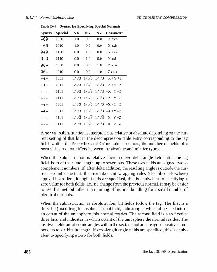
B.12.7 Normal Subinstruction 3D GEOMETRY COMPRESSION
486
cur-tag
a
tago’s-cur-here)g asier
r of
s as ofd at
. Thenum-uiv-
A Normal subinstruction is interpreted as relative or absolute depending on therent setting of that bit in the decompression table entry corresponding to thefield. Unlike thePosition andColor subinstructions, the number of fields ofNormal instruction differs between the absolute and relative types.
When the subinstruction is relative, there are two delta angle fields after thefield, both of the same length, up to seven bits. These two fields are signed twcomplement numbers. If, after delta addition, the resulting angle is outside therent sextant or octant, the sextant/octant wrapping rules (described elsewapply. If zero-length angle fields are specified, this is equivalent to specifyinzero value for both fields, i.e., no change from the previous normal. It may be eato use this method rather than turning off normal bundling for a small numbeidentical normals.
When the subinstruction is absolute, four bit fields follow the tag. The first ithree-bit (fixed-length) absolute sextant field, indicating in which of six sextantan octant of the unit sphere this normal resides. The second field is also fixethree bits, and indicates in which octant of the unit sphere the normal resideslast two fields are absolute angles within the sextant and are unsigned positivebers, up to six bits in length. If zero-length angle fields are specified, this is eqalent to specifying a zero for both fields.
Table B-4 Syntax for Specifying Special Normals
Syntax Special NX NY NZ Comment
+00 0000 1.0 0.0 0.0 +X axis
-00 0010 –1.0 0.0 0.0 –X axis
0+0 0100 0.0 1.0 0.0 +Y axis
0-0 0110 0.0 –1.0 0.0 –Y axis
00+ 1000 0.0 0.0 1.0 +Z axis
00- 1010 0.0 0.0 –1.0 –Z axis
+++ 0001 +X +Y +Z
++- 0011 +X +Y –Z
+-+ 0101 +X –Y +Z
+-- 0111 +X –Y –Z
-++ 1001 –X +Y +Z
-+- 1011 –X +Y –Z
--+ 1101 –X –Y +Z
--- 1111 –X –Y –Z
1 3⁄ 1 3⁄ 1 3⁄
1 3⁄ 1 3⁄ 1 3⁄
1 3⁄ 1 3⁄ 1 3⁄
1 3⁄ 1 3⁄ 1 3⁄
1 3⁄ 1 3⁄ 1 3⁄
1 3⁄ 1 3⁄ 1 3⁄
1 3⁄ 1 3⁄ 1 3⁄
1 3⁄ 1 3⁄ 1 3⁄
The Java 3D API Specification
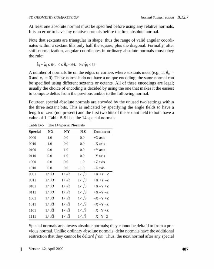
3D GEOMETRY COMPRESSION Normal SubinstructionB.12.7
als.
ordi-fterbey
t =l can
egal;siest
ithinve ave a
pre-onall
At least one absolute normal must be specified before using any relative normIt is an error to have any relative normals before the first absolute normal.
Note that sextants are triangular in shape; thus the range of valid angular conates within a sextant fills only half the square, plus the diagonal. Formally, ashift normalization, angular coordinates in ordinary absolute normals must othe rule:
A number of normals lie on the edges or corners where sextants meet (e.g., a0 and = 0). These normals do not have a unique encoding; the same normabe specified using different sextants or octants. All of these encodings are lusually the choice of encoding is decided by using the one that makes it the eato compute deltas from the previous and/or to the following normal.
Fourteen special absolute normals are encoded by the unused two settings wthe three sextant bits. This is indicated by specifying the angle fields to halength of zero (not present) and the first two bits of the sextant field to both havalue of 1. Table B-5 lists the 14 special normals
Special normals are always absolute normals; they cannot be delta’d to from avious normal. Unlike ordinary absolute normals, delta normals have the additirestriction that they cannot be delta’dfrom. Thus, the next normal after any specia
Table B-5 The 14 Special Normals
Special NX NY NZ Comment
0000 1.0 0.0 0.0 +X axis
0010 –1.0 0.0 0.0 –X axis
0100 0.0 1.0 0.0 +Y axis
0110 0.0 –1.0 0.0 –Y axis
1000 0.0 0.0 1.0 +Z axis
1010 0.0 0.0 –1.0 –Z axis
0001 +X +Y +Z
0011 +X +Y –Z
0101 +X –Y +Z
0111 +X –Y –Z
1001 –X +Y +Z
1011 –X +Y –Z
1101 –X –Y +Z
1111 –X –Y –Z
θ̂6 φ̂6+ 64≤ 0 θ̂6≤ 64< 0 φ̂6≤ 64<, ,
θ̂n
φ̂n
1 3⁄ 1 3⁄ 1 3⁄
1 3⁄ 1 3⁄ 1 3⁄
1 3⁄ 1 3⁄ 1 3⁄
1 3⁄ 1 3⁄ 1 3⁄
1 3⁄ 1 3⁄ 1 3⁄
1 3⁄ 1 3⁄ 1 3⁄
1 3⁄ 1 3⁄ 1 3⁄
1 3⁄ 1 3⁄ 1 3⁄
487Version 1.2, April 2000
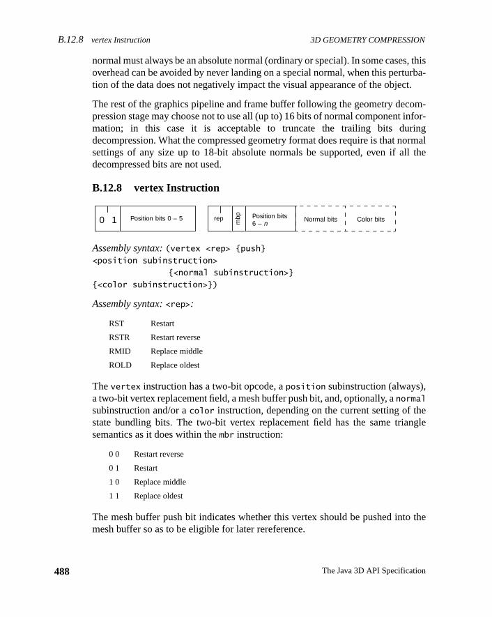
B.12.8 vertex Instruction 3D GEOMETRY COMPRESSION
488
, thisurba-ct.
om-nfor-ingormall the
engle
the
normal must always be an absolute normal (ordinary or special). In some casesoverhead can be avoided by never landing on a special normal, when this perttion of the data does not negatively impact the visual appearance of the obje
The rest of the graphics pipeline and frame buffer following the geometry decpression stage may choose not to use all (up to) 16 bits of normal component imation; in this case it is acceptable to truncate the trailing bits durdecompression. What the compressed geometry format does require is that nsettings of any size up to 18-bit absolute normals be supported, even if aldecompressed bits are not used.
B.12.8 vertex Instruction
Assembly syntax:(vertex <rep> {push}<position subinstruction>
{<normal subinstruction>}
{<color subinstruction>})
Assembly syntax:<rep>:
Thevertex instruction has a two-bit opcode, aposition subinstruction (always),a two-bit vertex replacement field, a mesh buffer push bit, and, optionally, anormal
subinstruction and/or acolor instruction, depending on the current setting of thstate bundling bits. The two-bit vertex replacement field has the same triasemantics as it does within thembr instruction:
The mesh buffer push bit indicates whether this vertex should be pushed intomesh buffer so as to be eligible for later rereference.
RST Restart
RSTR Restart reverse
RMID Replace middle
ROLD Replace oldest
0 0 Restart reverse
0 1 Restart
1 0 Replace middle
1 1 Replace oldest
Position bits 0 – 5 Position bits6 – n
Normal bits Color bits0 1 rep
mbp
The Java 3D API Specification
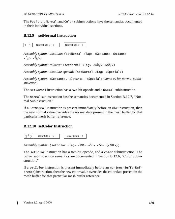
3D GEOMETRY COMPRESSION setColor InstructionB.12.10
ed
or-
that
bin-
the
ThePosition, Normal, andColor subinstructions have the semantics documentin their individual sections.
B.12.9 setNormal Instruction
Assembly syntax: absolute:(setNormal <Tag> <Sextant> <Octant>
< > < >)
Assembly syntax: relative:(setNormal <Tag> < > < >)
Assembly syntax: absolute special:(setNormal <Tag> <Special>)
Assembly syntax:<Sextant>, <Octant>, <Special>: same as for normal subin-struction.
ThesetNormal instruction has a two-bit opcode and aNormal subinstruction.
TheNormal subinstruction has the semantics documented in Section B.12.7, “Nmal Subinstruction.”
If a SetNormal instruction is present immediately before anmbr instruction, thenthe new normal value overrides the normal data present in the mesh buffer forparticular mesh buffer reference.
B.12.10 setColor Instruction
Assembly syntax:(setColor <Tag> <∆R> <∆G> <∆B> {<∆α>})
ThesetColor instruction has a two-bit opcode, and acolor subinstruction. Thecolor subinstruction semantics are documented in Section B.12.6, “Color Sustruction.”
If a setColor instruction is present immediately before anmbr (meshBufferRef-erence) instruction, then the new color value overrides the color data present inmesh buffer for that particular mesh buffer reference.
Normal bits 0 – 5 Normal bits 6 – n1 1
θ̂n φ̂n
∆θ̂n ∆φ̂n
Color bits 0 – 5 Color bits 6 – n1 0
489Version 1.2, April 2000
B.13 Semantics of Compressed Geometry Instructions 3D GEOMETRY COMPRESSION
490
by atheseple-
tionssedcom-les for
bitsbe
. Theec-log-plit
ied
fiveodes iss
g withded.di-of
areare-
B.13 Semantics of Compressed Geometry Instructions
The formal semantics of the compressed geometry format is best describedstate description of the decompression process. It must be emphasized thatstate descriptions are given to show the formal semantics, not an efficient immentation.
The next few sections will present such a state description. While this descripis intended to be a complete and unambiguous description of the compregeometry format and decompression semantics, in practice studying both thepression process and the decompression process, and studying code exampboth, is a better approach for the human understanding process.
B.13.1 Header and Body to Variable-Length Instruction
Compressed geometry instructions have a minimum length of eight bits (sixfor subinstructions). This allows all geometry decompression instructions tosplit into two physically separate bit sequences within the compressed streamfirst bit sequence is always of eight bits in length (six for subinstructions); the sond bit sequence contains the remaining bits of the instruction (if any). Thus aical stream ofN compressed geometry instructions, where each instruction is sinto two bit sequences Hi and Bi (i being from 0 toN – 1), is physically representedas
H0 B–1 H1 B0 H2 B1 … Hn–1 Bn–2 Hn Bn–1
Okay, so what is this “B–1”? All compressed geometry sequences have an impl(not physically present) H–1 of a nop opcode, thus B–1 is always present (startingat the eighth bit of the stream) as any valid variable-length nop body. (Justzeros, the minimum-length nop, is a good default.) Thus the implied nop opc“jump starts” the header-forwarded decompression process. This procesreversed at the end of the stream. Hn is a nop opcode, but no body is present, aBn–1 is the last bits of the stream. (As will be described, Bn–1 must end on a 32-bit aligned boundary.)
This is viable because all compressed geometry streams are presented alona total bit length of their contents, so no explicit end-of-stream marker is neeStreamsmustbe rounded up to the nearest full 64-bit word multiple by use of adtional variable-length nop instructions of appropriate lengths (within the bodythe stream, that is, their headers appear before Hn). This implies that Hn–1is usuallya nop instruction used to force alignment.
This “header-forwarding” shuffled representation is necessary for hardwdecompressors to operate efficiently. While this is not an issue for purely softw
The Java 3D API Specification
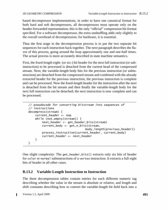
3D GEOMETRY COMPRESSION Variable-Length Instruction to InstructionB.13.2
at forn theat
tly to
te bithe fla-
es..
b-ssed
bin-readyletenextthecan
tagand
to a
based decompressor implementations, in order to have one canonical formboth hard and soft decompressors, all decompressors must operate only oheader-forwarded representation; this is the only “official” compression bit-formspecified. For a software decompressor, the extra unshuffling adds only slighthe overall overhead of decompression; for hardware, it is essential.
Thus the first stage in the decompression process is to put the two separasequences for each instruction back together. The next paragraph describes tvor of this process, going around the loop approximately one and one-half timThe actual process is more accurately described in state machine semantics
First, the fixed-length eight- (or six-) bit header for the next full instruction (or suinstruction) to be processed is detached from the current head of the comprestream. Next, the variable-length body bits for the previous instruction (or sustruction) are detached from the compressed stream and combined with the alextracted header for the previous instruction; the previous instruction is compand can be processed. Now the fixed-length header for the instruction after theis detached from the bit stream and then finally the variable-length body fornext full instruction can be detached; the next instruction is now complete andbe processed.
// pseudocode for converting bitstream into sequences of// instructionsdecompress(stream) { current_header <- nop while (not_empty(stream)) { next_header <- get_header_bits(stream) current_body <- get_n_bits(stream,
body_length(previous_header)) process_instruction(current_header, current_body) current_header <- next_header }}
One slight complexity: Theget_header_bits() extracts only six bits of headerfor color or normal subinstructions of avertex instruction. It extracts a full eightbits of header in all other cases.
B.13.2 Variable-Length Instruction to Instruction
The three decompression tables contain entries for each different numericdescribing whether the value in the stream is absolute or relative, and lengthshift constants describing how to convert the variable-length bit field back in
491Version 1.2, April 2000
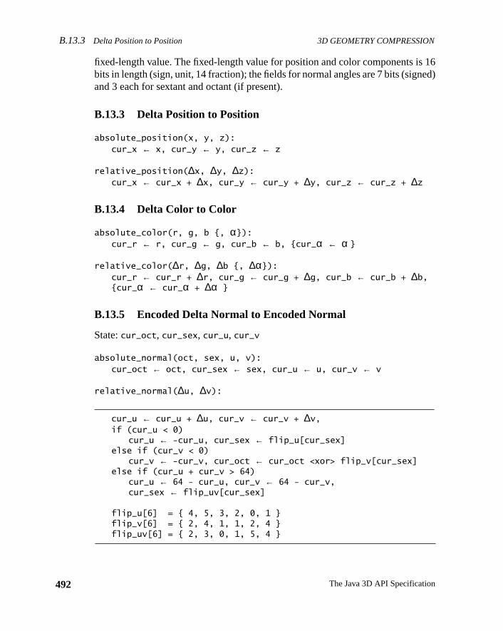
B.13.3 Delta Position to Position 3D GEOMETRY COMPRESSION
492
16ed)
fixed-length value. The fixed-length value for position and color components isbits in length (sign, unit, 14 fraction); the fields for normal angles are 7 bits (signand 3 each for sextant and octant (if present).
B.13.3 Delta Position to Position
absolute_position(x, y, z):cur_x ← x, cur_y ← y, cur_z ← z
relative_position(∆x, ∆y, ∆z):cur_x ← cur_x + ∆x, cur_y ← cur_y + ∆y, cur_z ← cur_z + ∆z
B.13.4 Delta Color to Color
absolute_color(r, g, b {, α}):cur_r ← r, cur_g ← g, cur_b ← b, {cur_α ← α }
relative_color(∆r, ∆g, ∆b {, ∆α}):cur_r ← cur_r + ∆r, cur_g ← cur_g + ∆g, cur_b ← cur_b + ∆b,{cur_α ← cur_α + ∆α }
B.13.5 Encoded Delta Normal to Encoded Normal
State:cur_oct, cur_sex, cur_u, cur_v
absolute_normal(oct, sex, u, v):cur_oct ← oct, cur_sex ← sex, cur_u ← u, cur_v ← v
relative_normal(∆u, ∆v):
cur_u ← cur_u + ∆u, cur_v ← cur_v + ∆v,if (cur_u < 0)
cur_u ← -cur_u, cur_sex ← flip_u[cur_sex]else if (cur_v < 0)
cur_v ← -cur_v, cur_oct ← cur_oct <xor> flip_v[cur_sex]else if (cur_u + cur_v > 64)
cur_u ← 64 - cur_u, cur_v ← 64 - cur_v,cur_sex ← flip_uv[cur_sex]
flip_u[6] = { 4, 5, 3, 2, 0, 1 }flip_v[6] = { 2, 4, 1, 1, 2, 4 }flip_uv[6] = { 2, 3, 0, 1, 5, 4 }
The Java 3D API Specification
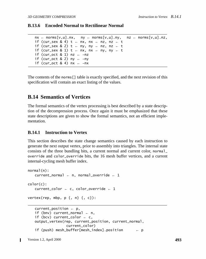
3D GEOMETRY COMPRESSION Instruction to VertexB.14.1
is
scrip-theseple-
tion tostate
nt
B.13.6 Encoded Normal to Rectilinear Normal
nx ← norms[v,u].nx, ny ← norms[v,u].ny, nz ← norms[v,u].nz,if (cur_sex & 4) t ← nx, nx ← nz, nz ← tif (cur_sex & 2) t ← ny, ny ← nz, nz ← tif (cur_sex & 1) t ← nx, nx ← ny, ny ← tif (cur_oct & 1) nz ← -nzif (cur_oct & 2) ny ← -nyif (cur_oct & 4) nx ← -nx
The contents of thenorms[] table is exactly specified, and the next revision of thspecification will contain an exact listing of the values.
B.14 Semantics of Vertices
The formal semantics of the vertex processing is best described by a state detion of the decompression process. Once again it must be emphasized thatstate descriptions are given to show the formal semantics, not an efficient immentation.
B.14.1 Instruction to Vertex
This section describes the state change semantics caused by each instrucgenerate the next output vertex, prior to assembly into triangles. The internalconsists of the three bundling bits, a current normal and current color,normal_
override andcolor_override bits, the 16 mesh buffer vertices, and a curreinternal-cycling mesh buffer index.
normal(n):current_normal ← n, normal_override ← 1
color(c):current_color ← c, color_override ← 1
vertex(rep, mbp, p {, n} {, c}):
current_position ← p,if (bnv) current_normal ← n,if (bcv) current_color ← c,output_vertex(rep, current_position, current_normal, current_color)if (push) mesh_buffer[mesh_index].position ← p
493Version 1.2, April 2000
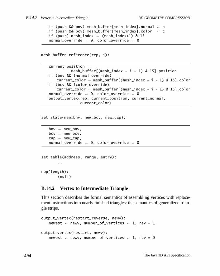
B.14.2 Vertex to Intermediate Triangle 3D GEOMETRY COMPRESSION
494
lace-rian-
if (push && bnv) mesh_buffer[mesh_index].normal ← nif (push && bcv) mesh_buffer[mesh_index].color ← cif (push) mesh_index ← (mesh_index+1) & 15normal_override ← 0, color_override ← 0
mesh buffer reference(rep, i):
current_position ←mesh_buffer[(mesh_index - i - 1) & 15].position
if (bnv && !normal_override)current_color ← mesh_buffer[(mesh_index - i - 1) & 15].color
if (bcv && !color_override)current_color ← mesh_buffer[(mesh_index - i - 1) & 15].color
normal_override ← 0, color_override ← 0output_vertex(rep, current_position, current_normal,
current_color)
set state(new_bnv, new_bcv, new_cap):
bnv ← new_bnv,bcv ← new_bcv,cap ← new_cap,normal_override ← 0, color_override ← 0
set table(address, range, entry):…
nop(length): (null)
B.14.2 Vertex to Intermediate Triangle
This section describes the formal semantics of assembling vertices with repment instructions into nearly finished triangles: the semantics of generalized tgle strips.
output_vertex(restart_reverse, newv):newest ← newv, number_of_vertices ← 1, rev = 1
output_vertex(restart, newv):newest ← newv, number_of_vertices ← 1, rev = 0
The Java 3D API Specification
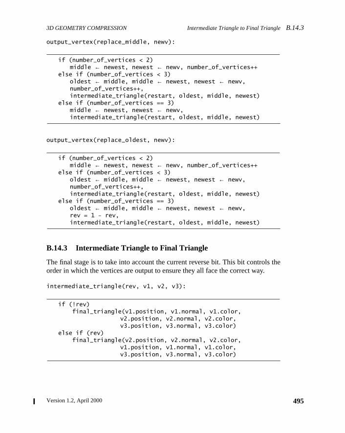
3D GEOMETRY COMPRESSION Intermediate Triangle to Final TriangleB.14.3
the
output_vertex(replace_middle, newv):
if (number_of_vertices < 2)middle ← newest, newest ← newv, number_of_vertices++
else if (number_of_vertices < 3)oldest ← middle, middle ← newest, newest ← newv,number_of_vertices++,intermediate_triangle(restart, oldest, middle, newest)
else if (number_of_vertices == 3)middle ← newest, newest ← newv,intermediate_triangle(restart, oldest, middle, newest)
output_vertex(replace_oldest, newv):
if (number_of_vertices < 2)middle ← newest, newest ← newv, number_of_vertices++
else if (number_of_vertices < 3)oldest ← middle, middle ← newest, newest ← newv,number_of_vertices++,intermediate_triangle(restart, oldest, middle, newest)
else if (number_of_vertices == 3)oldest ← middle, middle ← newest, newest ← newv,rev = 1 - rev,intermediate_triangle(restart, oldest, middle, newest)
B.14.3 Intermediate Triangle to Final Triangle
The final stage is to take into account the current reverse bit. This bit controlsorder in which the vertices are output to ensure they all face the correct way.
intermediate_triangle(rev, v1, v2, v3):
if (!rev) final_triangle(v1.position, v1.normal, v1.color,
v2.position, v2.normal, v2.color, v3.position, v3.normal, v3.color)
else if (rev) final_triangle(v2.position, v2.normal, v2.color,
v1.position, v1.normal, v1.color, v3.position, v3.normal, v3.color)
495Version 1.2, April 2000
B.15 Outline of Geometry Process 3D GEOMETRY COMPRESSION
496
om-ssedations
rmat,
suchcts
ofon
lizedasedhen
, notthat
r willdata
als.in-
oxnor-Z
hehus-
B.15 Outline of Geometry Process
Java 3D formally defines only the compressed geometry format and the decpression semantics. Authoring tools are free to employ whatever compregeometry algorithms they choose, as long as the results adhere to the specificdescribed in the previous sections.
However, to further document the semantics of the compressed geometry foan overview of one particular compressed geometry algorithm is given here.
B.15.1 Compressing Geometry Data
Group the geometry to be compressed into separate rigid objects. Typicallyobjects will be individually culled during rendering, so you should not join objetoo extensively prior to compression. In optimized systems, the granularityobject splitting will be computed by an algorithm that takes culling optimizatiinto account (both frustum and occlusion culling).
B.15.2 Convert to Generalized Mesh Format
Once a group of geometry has been identified, it is next converted into generamesh format. This is a complex step, and a number of topological analysis-balgorithms have been applied to it. Note that to reduce compression time, wspace is a less important issue than time, a compressor might only stripifymeshify. Alternatively, the triangles have to have come from somewhere, andin many cases is a tessellator of higher order surfaces. Such a tessellatoimplicitly know the mesh connectivity and may be able to generate the triangledirectly in the generalized mesh format.
The next step is the quantization of the geometry positions, colors, and/or normAll these quantizations can be varied within the geometry, but for simplicity a sgle fixed quantization of each is assumed here.
B.15.3 Position
Normalize the position data.
The containing bounding box for the object is computed. This is the minimal bsuch that all geometry vertices are contained within it. The vertices are then allmalized to be contained within this bounding box by first subtracting the XYlocation of the bounding box center from the vertex XYZ and then dividing all tXYZ vertex values by the half length of the longest side of the bounding box. Tall normalized positions will be within the±1 unit cube. A constant matrix trans
The Java 3D API Specification
3D GEOMETRY COMPRESSION NormalsB.15.4
ersepro-
ken.an-istthe
-rflowating
-2
ignthe
hene
form corresponding to an offset to the center of the bounding box and an invscale by the half length of the longest side of the bounding box are created as alogue for the geometry data. Note that in practice a little more care must be taThe greatest positive value is actually , when positions are qutized to n bits. By symmetry, the smallest negative value allowed
. The value –1 (only sign bit set, all other bits 0) is explicitly noallowed. Thus when computing the scale factor (and center) that will normalizegeometry, the actual representation range needs to be taken into account.
Quantize the position data.
Assuming that position data is to be quantized ton bits, each vertex position com-ponent should be multiplied by the value of 2n and then rounded down to the nearest integer. If rounded to the nearest integer, or rounded up, the value may ovethe representation. Once again the goal is to take numbers from a given flopoint range and represent all of them within ann-bit fixed point range.
B.15.4 Normals
Normalize the normals.
Each normal should be normalized to unit length.
Quantize the XYZ components of the normal to 14 bits accuracy.
Each normal component should be multiplied by 214, rounded to the nearest integer, and then converted back to floating-point representation and divided by 14.
Fold the XYZ components of the normal to the positive (prime) octant.
If an XYZ component of the normal is negative, invert it and save the original sbits as a three-bit octant value. It is important when compressing always to stripsign bits off first before applying sextant folding and to reverse the process wdecompressing. Note that the octant bits read left to right: the upper bit is for thx-axis, the middle for they-axis, and the lowermost is for thez-axis.
oct = 0;if(nx < 0.0) oct |= 4, nx = -nxif(ny < 0.0) oct |= 2, ny = -nyif(nz < 0.0) oct |= 1, nz = -nz
2n 1– 1–( ) 2n 1–⁄
2n 1– 1–( )– 2n 1–⁄
497Version 1.2, April 2000
B.15.5 Colors 3D GEOMETRY COMPRESSION
498
ls indexult isepre-t thismalscom-
fullnor-
, thermal
Fold the normal to the nX≥ nZ ≥ nY sextant.
Check (in exactly the following order):
sex = 0;if (nx < ny) t = nx, nx = ny, ny = t, sex |= 1if (nz < ny) t = ny, ny = nz, nz = t, sex |= 2if (nx < nz) t = nx, nx = nz, nz = t, sex |= 4
Match the nearest quantized normal representation.
Take the dot product of the normal with each of the quantized reference normathe table for the specified number of quantized normal bits. That u,v normal infor the reference normal that gives the greatest (nearest unity) dot product resthe new quantized normal representation (along with the octant and sextant rsentation). (There are more efficient ways to compute the same results.) Apoint there are no specific tie-breaking rules when two (or more) reference norproduce the same candidate dot product results. Technically this is purely apressor internal issue.
Check for special normals.
The u,v normal index generated by the previous stage will generally be in the7-bit range of the normal grid space. In this space, the two classes of specialmals occur when u = 64, v = 0, and when u = 0, v = 64. When this is detectedsextant and octant bits must be examined to produce the proper special noencoding:
if (u == 64 && v == 0) { /* Six coordinate axis case */ if (sex == 0 || sex == 2) /* +/- x-axis */ special = ((oct & 4)?0x2:0);
else if (sex == 3 || sex == 1) /* +/- y-axis */ special = 4 | ((oct & 2)?0x2:0);
else if (sex == 5 || sex == 4) /* +/- z-axis */ special = 0x8 | ((oct & 1)?0x2:0);
} else if (u == 0 && v == 64) /* Eight mid point case */
special = (oct<<1) | 1;
B.15.5 Colors
To begin with, the colors are assumed to be in a 0.0 to 0.9 representation.
The Java 3D API Specification
3D GEOMETRY COMPRESSION Normal Delta Code StatisticsB.15.9
t
epre-
. Foronent
bitns.
de.the
t-sign
xtant,
mpo-r of
rmal,rulesed.dges
rs are
Quantize the color values.
Assuming that color data is to be quantized ton bits, each vertex color componen(R, G, B, and optionallyα) should be multiplied by the value of 2n and thenrounded down to the nearest integer. Just as with positions, there is no true rsentation of positive unity.
B.15.6 Collect Delta Code Statistics
Make a pass in generalized mesh order through all vertices in the geometryeach successive pair of vertices, compute the difference between their compvalues, compute the bit length of this (signed) difference, and histogram thislength. Specifics for each component type are detailed in the following sectio
B.15.7 Position Delta Code Statistics
Compute∆X, ∆Y, and∆Z. Determine which of these has the greatest magnituCompute the number of bits for this component, including one sign bit. This islength to be histogrammed for positions.
B.15.8 Color Delta Code Statistics
Compute∆R,∆G,∆B, and∆α (if present). Determine which of these has the greaest magnitude. Compute the number of bits for this component, including onebit. This is the length to be histogrammed for colors.
B.15.9 Normal Delta Code Statistics
For a given pair of normals, check to see if they have the same octant and seand that neither is a special normal. If so, compute∆U and∆V. Determine whichof these has the greatest magnitude. Compute the number of bits for this conent, including one sign bit. This is the length to be histogrammed for this painormals.
If the normals have different sextants and/or octants, but neither is a special nocheck to see if their sextants share an edge. If so, the special normal wrappingfrom Section B.8.3, “Special Warping Rules for Delta Normals,” can be appliDepending on what type of edge they share, the delta including the change in eis encoded in one of three ways: U +∆U < 0, V + ∆V < 0, and U +∆U + V + ∆V> 64. Each case is discussed in the following paragraphs. The sextant numbefrom the binary codes shown in Figure B-3.
499Version 1.2, April 2000
B.15.9 Normal Delta Code Statistics 3D GEOMETRY COMPRESSION
500
nt.is for
duermalt andfaultltat theck ofgen-
ion,me as
ibleal no,
ormalnt, andor-
e indif-
ormal,withput
Sextants 0 and 4, 1 and 5, and 2 and 3 share the U = 0edge. When crossing thisboundary,∆U becomes ~U –last_u. This will generate a negativecur_u valueduring decompression, which causes the decompressor to invertcur_u and look upthe new sextant in a table.
Sextants 0 and 2, 1 and 3, and 4 and 5 share the U + V = 64 edge.∆U becomes 64– U – last_u, and∆V becomes 64 – V –last_v. Whencur_u + cur_v > 64, thedecompressor setscur_u = 64 –cur_u andcur_v = 64 –cur_v, and a table lookupdetermines the new sextant.
Each sextant shares the V = 0edge with its corresponding sextant in another octaWhen in sextants 1 or 5, the normal moves across the X-axis, across the Y-axsextants 0 or 4, and across the Z-axis for sextants 2 or 3.∆V becomes ~V –last_v. The decompressor inverts a negativecur_v and performs a table lookup for amask to exclusive-OR with the current octant value.
Note: When using the normal wrapping rules, a subtle bug can be introducedto the ambiguity of normals on a shared edge between two sextants. The noencoding rules have unambiguous tie-breaking rules to determine which octansextant a given normal resides in. However, the wrapping rules assume by dethat a delta’d normal is in thesamesextant and octant as its predecessor if the delanded only on an edge. This is subtly different than the sextant and octant thaencoding rules might have suggested. The proper procedure is to keep trawhich octant and sextant a decompressor would believe that the normals beingerated would lie in. When the normal to delta to lands on an edge of this regchange its sextant and octant from what the encoding rules suggest are the sawhere it is now delta-ing from. This change in default encoding is permissbecause the rectilinear normal encoded by values on a sextant edge is identicmatter which sextant claims ownership.
Otherwise the normals cannot be delta encoded, and so the second (target) nmust be represented by an absolute reference to its three octant, three sexta2 n-bit u, v addresses. This is the length to be histogrammed for this pair of nmals.
Note: Slightly higher compression density can be achieved at a slight expensrepresentation accuracy by avoiding special normals when delta and wrappingferences are generating compact results. Instead of generating the special na near-by nonspecial normal can be generated allowing for compact deltas. Asany compression technique that intentionally further modifies or distorts the in
The Java 3D API Specification
3D GEOMETRY COMPRESSION Compressed Geometry Assembly SyntaxB.16
ssor
ssionngthsessedtive/
algo-e tree.ode,
st beg the
shuf-.
er foreome-
rmatanSCIIm-ing
. TheBoths tools.
data, doing this normal perturbation must be a policy choice of the compreitself and subject to quality constraints of the user.
B.15.10 Assign Huffman Tags
Encode data into variable-bit length compressed geometry instructions.
One can use an algorithm similar to the one used by the JPEG image comprestandard. The main differences are how codes are reassigned when their leexceed the maximum code length, how the data bits are encoded in the comprdata stream, and also how they support additional attributes for codes (relaabsolute, how many bits of left shift).
The frequencies of the data lengths are used as leaf nodes in a binary tree. Therithm used to generate the tree places the less-frequent codes deeper in thAfter the tree is built, the traversal path to a leaf node becomes its Huffman cand the depth in the tree becomes its code length.
Codes generated with a length greater than six, the maximum code length, mushortened. These nodes are merged with more frequent nodes by increasinnumber of sign bits included with the smaller data length.
B.15.11 Assemble the Pieces into a Bit Stream
Given the sequence of variable-bit-length compressed geometry instructions,fle the first eight (six) bits of each instruction ahead of its predecessor’s body
B.16 Compressed Geometry Assembly Syntax
This section describes the assembly syntax for both the input to an assemblcompressed geometry, and for the output of a disassembler of compressed gtry.
The concept of a verbose ASCII assembly syntax for a compressed binary fomay seem like an oxymoron, but in fact a well-defined assembly format isinvaluable aid to debugging both compressors and decompressors. The Aassembly format isnotmeant to be a representation used for the transport of copressed geometry; rather, it is a debugging aid for those involved in programmcompressors and decompressors and building hardware decompressorsassembly format is also useful for generating and understanding test vectors.an assembler and a disassembler are available as stand-alone C programs a
501Version 1.2, April 2000
B.16 Compressed Geometry Assembly Syntax 3D GEOMETRY COMPRESSION
502
Java-ptionutput
ationd to
essedhen
sem-com-ssedisas-pres-rs ofeithered asex
ersh-op-arsefor-gthlet-
anandis
te
e
ndwn.me
For generating compressed geometry programmatically, a number of C- andbased low-level compression tools are also available. With the possible exceof test vectors, software-based compressors should use these direct binary oroutines; having a compressor generate an intermediate ASCII file representonly then to be assembled into binary is needlessly inefficient. If there is a neeexamine the output of a compressor in a human readable form, a binary comprgeometry file can always be disassembled into ASCII by the disassembler wneeded.
Because compressed geometry is a tightly encoded binary format, to make disbled output more understandable, it is appropriate to perform some partial depression optionally before generating the text output. Thus the compregeometry disassembler supports multiple levels of decompression during dsembly. On the other hand, the compressed geometry assembler is not a comsor and thus supports as input the only lowest level syntax. There are five layesuccessively more decompressed disassembly, with each level printed usingdecimal or hex numbers. The five layers and two numeric formats are expressten different levels of disassembly (with every other level just indicating that houtput for integer fields):
1. Nearly raw. After a symbolic opcode, decimal (or optionally, hex) numbare printed for the modified Huffman tag field and for all data fields witout any additional interpretation, scaling, or un-delta-ing, except that prer signed/unsigned semantics are followed. The only processing is to pthe incoming bit stream into bit fields and to undo the effects of headerwarding. The modified Huffman tag is used only to determine the lenof the tag field and the following data fields. The opcode has no trailingter modifiers (as documented below); this indicates level 1.
2. Same as level 1, but printed using hex numbers (preceded with a0x suffix).
3. Modified Huffman tag expanded. The properties of the modified Huffmtag are shown in line: the length of the tag, the length of the data fields,the left normalization shift for the field. The absolute/relative bit valueshown by appending the letter ‘A’ or ‘R’ to the opcode (or ‘S’ for absolu‘special’ normals).
4. Same as level 3, but printed using hex numbers (preceded with th0x
suffix).
5. Normalized. The left normalization shift is applied to the data fields, athe specific properties of the modified Huffman tag are no longer shoTo differentiate from level 2, the letter ‘N’ is appended to the opcode naafter the absolute/relative/special letter.
The Java 3D API Specification
3D GEOMETRY COMPRESSION Compressed Geometry Assembly SyntaxB.16
e
talared
e
-bitere
esees,
isen
hex
the
ithertruc-
id:
6. Same as level 5, but printed using hex numbers (preceded with th0x
suffix).
7. Un-delta’d. Like level 3, but relative values have had the running toadded to them to show what the current full value is. Absolute valuesunchanged from level 3. To differentiate from level 4, an ‘A’ suffix is addeto the lengthening opcode name.
8. Same as level 7, but printed using hex numbers (preceded with th0x
suffix).
9. Floating point. While up to now all values have been subsets of 16integers, before conversion to integer and quantization, most values wfloating-point numbers in the 0 to 1.0 or−1.0 to 1.0 range. Level 5 showsthe values as floating-point numbers, but it must be cautioned that thdata fields, while similar to the input uncompressed unquantized valuwill usually be slightly different in value than the original data. Thfloating-point output format is primarily included as a convenience wha user wants to understand the data closer to the original space.
10. Same as level 9, but non-floating-point numbers are printed usingnumbers (preceded with the0x suffix).
Once again while the dissembler supports all 10 levels of output options,assembler supports only levels 1 and 2.
The syntax is fairly simple. Because the setting Colors or Normals can be estandalone instructions or components of a vertex instruction, parenthetic instion grouping (lisp style) is used to make the ownership of arguments clear.
As an example, following is the disassembly (print level 1) of a four-sided pyram
(nop 0)(setTable Position 32-47 2 4 Rel)(setTable Position 56-63 3 4 Rel)(setTable Position 0-31 12 4 Rel)(setTable Position 48-55 12 4 Abs)(setTable Normal 0-31 5 0 Rel)(setTable Normal 32-63 6 0 Abs)(setTable Color 32-63 2 8 Rel)(setTable Color 0-31 8 8 Abs)(setState normalsBundled colorsUnbundled alphaUnbundled)(setState normalsBundled colorsUnbundled alphaUnbundled)(setColor 0 127 51 12)(setState normalsBundled colorsUnbundled alphaUnbundled)(setColor 32 0 0 0)(vertex RST (Position 48 -2047 -2047 -205)
(Normal 32 4 --+ 44 0))
503Version 1.2, April 2000
B.17 Compressed Geometry Instruction Verifier 3D GEOMETRY COMPRESSION
504
validple-vali-
also.
n itsd runro-
ationption.atemust
ge istion
zed
fol-t:
(vertex RMID (Position 0 2047 -2 0)(Normal 32 5 +++ 44 0))
(vertex ROLD (Position 0 0 -2047 409)(Normal 0 14 0))
(vertex ROLD (Position 0 2047 -2047 -409)(Normal 32 4 +-+ 44 0))
(vertex ROLD (Position 56 2 0 0)(Normal 32 4 --+ 44 0))
(vertex RST (Position 0 2047 -2 0)(Normal 32 00-))
(vertex RMID (Position 0 -2047 2 0)(Normal 32 00-))
(vertex ROLD (Position 32 -2 0 0)(Normal 32 00-))
(nop 19)(nop 29)
B.17 Compressed Geometry Instruction Verifier
This section describes the rules for determining if a given binary sequence is acompressed geometry block. These rules have been programmatically immented in a compressed geometry verifier, a stand-alone C program that candate a given file containing a Compressed Geometry object. The verifier isavailable in a utility package in both C and Java for use within larger systems
In theory, every producer of compressed geometry should run such a verifier ooutput as a final check, and every consumer of compressed geometry shoulsuch a verifier on any input as an initial check. In practice, for well-debugged pgrams and hardware implementations with error detection, a separate verificpass may not always be necessary, but it should always be available as an o(It is also important to note that just passing the verifier is not sufficient to indicthat a compressed geometry compressor is functioning properly; the outputalso be examined visually for other types of error.)
When the stand-alone verifier finds a violation, an appropriate error messaprinted out. This is quite useful when debugging compressors. The implementaof the verifier is effectively an augmented decompressor, in which the uninitialistate is kept track of and additional error checking is applied.
For a Compressed Geometry object to be valid, it must adhere to at least thelowing rules, along with the restrictions described in the rest of this documen
The Java 3D API Specification
3D GEOMETRY COMPRESSION Compressed Geometry Instruction VerifierB.17
ur 8-ork
p in-tionanyirst
owedbe
pe,ieven(s)
that-om ae thatse-so assedy can
truc-
om-
d be-in-
Table
Rule 1: Size, Alignment and Byte Order
Every compressed geometry is a sequence of binary data a multiple of fobit bytes in size, starting on an aligned 32-bit boundary, represented in netwbyte order.
Rule 2: Beginnings
Every compressed geometry sequence starts with the body field of a nostruction. Initial process proceeds as if a forwarded header of a nop instruchad just been seen. The length field of this nop instruction body can be oflegal length, though usually by convention the length field is 0; thus the fbody consists of five zeros.
Rule 3: Endings
The last header in a compressed geometry sequence is a nop. This is follby the body of the next-to-last instruction. This preceding instruction canany instruction, and its body can be of any valid length for that instruction tybut the body must end on a four byte 32-bit word aligned boundary. To achthis, usually the next-to-last and possibly the next-to-next-to-last instructioare also nops, with lengths chosen to satisfy the ending requirement. Notethe body for the last instruction (the nop) isnot present in the compressed geometry sequence. The end of the compressed geometry is determined frseparately specified size outside of the compressed geometry proper. Notthis ending convention is symmetrical with the starting convention; thequential concatenation of two valid Compressed Geometry objects is alvalid Compressed Geometry object. For hardware, after a valid CompreGeometry object has been executed, another valid compressed geometrbe executed without any pipeline flushes if desired.
Rule 4: Reserved Bits
Any bits or bit fields described as reserved in a compressed geometry instion must be filled with zeros.
Rule 5: Valid Opcodes
Only the seven defined instruction opcodes may be present in a valid Cpressed Geometry object.
Rule 6: No Defaults
All state used in the processing of compressed geometry must be definefore it is used; there are no implicit defaults for any of the state. The statecludes the contents of the decompression tables as defined by the set
505Version 1.2, April 2000
B.17 Compressed Geometry Instruction Verifier 3D GEOMETRY COMPRESSION
506
theen-
d byolore de-ionsal oral-hichuff-
renceecialy notting
s forl or
ticu-ob-
ble asn-
a
malt, uf val-alid,
bin-d
instruction; the three bundling bits as defined by the setState instruction;contents of the mesh buffer as defined by vertex instructions with pushabled; and the current position, normal, and color (and alpha), as defineabsolute settings in vertex instructions, setNormal instructions, and setCinstructions. Note that this does not mean that all possible state needs to bfined within a Compressed Geometry object. For example, only those portof the decompression tables actually referenced by a vertex or setNormsetColor instruction need be initialized first. The bits specified by setStateways need to be referenced, unless there are no vertex instructions, wwould occur only in a geometry-less Compressed Geometry object. Mesh ber elements need only be defined if they are accessed by mesh buffer refeinstructions. The current normal and the current color (and alpha) are spcases; if they are not used within a Compressed Geometry object, they maneed to be initialized, depending on the semantics of the outer incorporagraphics API.
Specifically in a valid compressed geometry sequence, no relative valuepositions, normals, colors (or alpha) may appear in a vertex or setNormasetColor instruction until after an absolute value has appeared for that parlar item. There is no inheritance between different Compressed Geometryjects, each must be entirely standalone when it comes to state.
Rule 7: State Changes Immediately
State changed by setState and setTable instructions is in force and availaof next instruction. (This specifically disallows pipelined hardware implemetations from changing the semantics to force user-visible delay slots.)
Rule 8: Valid XYZ Positions
Executing the position field of a vertex instruction will always result insigned 16-bit fixed-point value for the currentx, y, andzposition state. All pos-sible bit values are valid for these fields.
Rule 9: Valid Sextant Octant u v Normals
Executing a setNormal instruction, or executing (when present) the norsubinstruction of a vertex instruction, will result in updated sextant, octanand v fields. The wrapping semantics described earlier define the subset oid values and delta operations allowed for these fields. If these fields are vthen a valid conversion back to a rectilinear Nx, Ny, Nz value is defined.
Rule 10: Valid RGB{α} Color
Executing a setColor instruction, or executing (when present) the color sustruction of a vertex instruction, will always result in a signed 16-bit fixe
The Java 3D API Specification
3D GEOMETRY COMPRESSION Compressed Geometry Instruction VerifierB.17
s in aand
o-ing isple,by
types lefttingableis
r, aner-es to.
llowetry
point value for the current R, G, B (and sometimesα) color state. Only positivevalues are valid for these fields.
Rule 11: What Is Outside the Scope of These Rules
The results of executing a sequence of compressed geometry instructionvalid Compressed Geometry object is a sequence of specific vertex valuesconnectivity information for triangles (or lines or points). What further prcessing this output stream is subject to, and the semantics of this processoutside the scope of the specification of compressed geometry. For examthe semantics of transformation, lighting, and shading are not specifiedcompressed geometry. Note that even the semantic interpretation of whatof color parameter the “color” values generated by compressed geometry iundefined by the Compressed Geometry specification; this is up to the lighequation (or for realistic rendering systems, more generally the programmshader) of the outer incorporating graphics API. Specifically no implicationmade as to whether the “color” value is an ambient color, a diffuse colospecular color, an emissive color, some combination thereof, or a more gealized value used by a programmable shader. This, of course, also appliany interpretation of theα value, which may or may not be an opacity value
As described earlier, for a Compressed Geometry object to be valid, it must fothese rulesplusadhere to the other constraints on individual compressed geominstructions described in the rest of this document.
507Version 1.2, April 2000

Version 1.2, April 2000
A P P E N D I X C
onust
singmustmodel
er toove,doodel
ix-ker,ges
ase,yandlaynd
sorsthe
View Model Details
AN application programmer writing a 3D graphics program that will deploya variety of platforms must anticipate the likely end-user environments and mcarefully construct the view transformations to match those characteristics ua low-level API. This appendix addresses many of the issues an applicationface and describes the sophisticated features that Java 3D’s advanced viewprovides.
C.1 An Overview of the Java 3D View Model
Both camera-based and Java 3D–based view models allow a programmspecify the shape of a view frustum and, under program control, to place, mand reorient that frustum within the virtual environment. However, how theythis varies enormously. Unlike the camera-based system, the Java 3D view mallows slaving the view frustum’s position and orientation to that of a sdegrees-of-freedom tracking device. By slaving the frustum to the tracJava 3D can automatically modify the view frustum so that the generated imamatch the end-user’s viewpoint exactly.
Java 3D must handle two rather different head-tracking situations. In one cwe rigidly attach a tracker’sbase, and thus its coordinate frame, to the displaenvironment. This corresponds to placing a tracker base in a fixed positionorientation relative to a projection screen within a room, to a computer dispon a desk, or to the walls of a multiple-wall projection display. In the secohead-tracking situation, we rigidly attach a tracker’ssensor, not its base, to thedisplay device. This corresponds to rigidly attaching one of that tracker’s sento a head-mounted display and placing the tracker base somewhere withinphysical environment.
509
C.2 Physical Environments and Their Effects VIEW MODEL DETAILS
510
lica-t’s
mbut
ntly
ith arpetorndererctlyad-had
oomet’sflu-thenif therep-
om-the
nifi-has
er’s
C.2 Physical Environments and Their Effects
Imagine an application where the end user sits on a magic carpet. The apption flies the user through the virtual environment by controlling the carpelocation and orientation within the virtual world. At first glance, it might seethat the application also controls what the end user will see—and it does,only superficially.
The following two examples show how end-user environments can significaaffect how an application must construct viewing transformations.
C.2.1 A Head-Mounted Example
Imagine that the end user sees the magic carpet and the virtual world whead-mounted display and head tracker. As the application flies the cathrough the virtual world, the user may turn to look to the left, to the right,even toward the rear of the carpet. Because the head tracker keeps the reinformed of the user’s gaze direction, it might not need to draw the scene direin front of the magic carpet. The view that the renderer draws on the hemount’s display must match what the end user would see if the experienceoccurred in the real world.
C.2.2 A Room-Mounted Example
Imagine a slightly different scenario where the end user sits in a darkened rin front of a large projection screen. The application still controls the carpflight path; however, the position and orientation of the user’s head barely inences the image drawn on the projection screen. If a user looks left or right,he or she sees only the darkened room. The screen does not move. It’s asscreen represents the magic carpet’s “front window” and the darkened roomresents the “dark interior” of the carpet.
By adding a left and right screen, we give the magic carpet rider a more cplete view of the virtual world surrounding the carpet. Now our end user seesview to the left or right of the magic carpet by turning left or right.
C.2.3 Impact of Head Position and Orientation on the Camera
In the head-mounted example, the user’s head position and orientation sigcantly affects a camera model’s camera position and orientation but hardlyany effect on the projection matrix. In the room-mounted example, the us
The Java 3D API Specification
VIEW MODEL DETAILS Room-Mounted Coordinate SystemsC.3.1
osi-
ct thetheent
sate
g onead-om-tem
sys-sys-the
nce
stemvir-the
tem
the
head position and orientation contributes little to a camera model’s camera ption and orientation; however, it does affect the projection matrix.
From a camera-based perspective, the application developer must construcamera’s position and orientation by combining the virtual-world component (position and orientation of the magic carpet) and the physical-world compon(the user’s instantaneous head position and orientation).
Java 3D’s view model incorporates the appropriate abstractions to compenautomatically for such variability in end-user hardware environments.
C.3 The Coordinate Systems
The basic view model consists of eight or nine coordinate systems, dependinwhether the end-user environment consists of a room-mounted display or a hmounted display. First, we define the coordinate systems used in a romounted display environment. Next, we define the added coordinate sysintroduced when using a head-mounted display system.
C.3.1 Room-Mounted Coordinate Systems
The room-mounted coordinate system is divided into the virtual coordinatetem and the physical coordinate system. Figure C-1 shows these coordinatetems graphically. The coordinate systems within the grayed area exist invirtual world; those outside exist in the physical world. Note that the coexistecoordinate system exists in both worlds.
C.3.1.1 The Virtual Coordinate Systems
The Virtual World Coordinate System
The virtual world coordinate system encapsulates the unified coordinate syfor all scene graph objects in the virtual environment. For a given View, thetual world coordinate system is defined by the Locale object that containsViewPlatform object attached to the View. It is a right-handed coordinate syswith +x to the right, +y up, and +z toward the viewer.
The ViewPlatform Coordinate System
The ViewPlatform coordinate system is the local coordinate system ofViewPlatform leaf node to which the View is attached.
511Version 1.2, April 2000
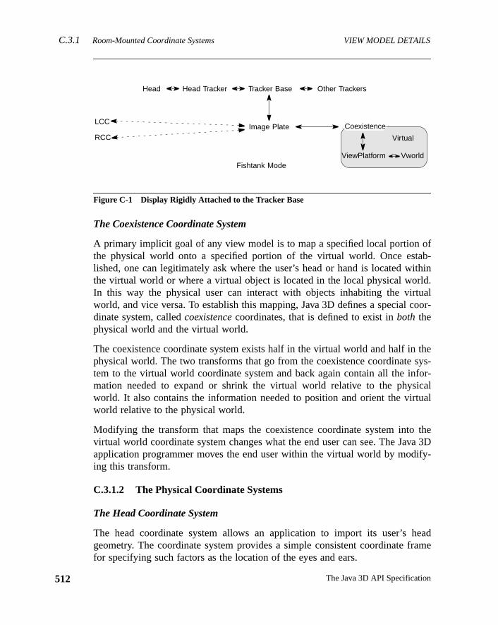
C.3.1 Room-Mounted Coordinate Systems VIEW MODEL DETAILS
512
ofab-ithinld.ualcoor-
thesys-for-icalual
theva 3Dify-
eadrame
Figure C-1 Display Rigidly Attached to the Tracker Base
The Coexistence Coordinate System
A primary implicit goal of any view model is to map a specified local portionthe physical world onto a specified portion of the virtual world. Once estlished, one can legitimately ask where the user’s head or hand is located wthe virtual world or where a virtual object is located in the local physical worIn this way the physical user can interact with objects inhabiting the virtworld, and vice versa. To establish this mapping, Java 3D defines a specialdinate system, calledcoexistencecoordinates, that is defined to exist inboth thephysical world and the virtual world.
The coexistence coordinate system exists half in the virtual world and half inphysical world. The two transforms that go from the coexistence coordinatetem to the virtual world coordinate system and back again contain all the inmation needed to expand or shrink the virtual world relative to the physworld. It also contains the information needed to position and orient the virtworld relative to the physical world.
Modifying the transform that maps the coexistence coordinate system intovirtual world coordinate system changes what the end user can see. The Jaapplication programmer moves the end user within the virtual world by moding this transform.
C.3.1.2 The Physical Coordinate Systems
The Head Coordinate System
The head coordinate system allows an application to import its user’s hgeometry. The coordinate system provides a simple consistent coordinate ffor specifying such factors as the location of the eyes and ears.
Head Head Tracker Tracker Base
Image Plate
Other Trackers
Fishtank Mode
Coexistence
ViewPlatform Vworld
Virtual
LCC
RCC
The Java 3D API Specification
VIEW MODEL DETAILS Head-Mounted Coordinate SystemsC.3.2
sys-t the
leftfinedordi-
edomystem
withlativetiald to
temsstemssys-thebothom-rdi-
sys-
withleft
t the
l
The Image Plate Coordinate System
The image plate coordinate system corresponds with the physical coordinatetem of the image generator. The image plate is defined as having its origin alower left-hand corner of the display area and as lying in the display area’sXYplane. Note that image plate is a different coordinate system than eitherimage plate or right image plate. These last two coordinate systems are dein head-mounted environments only (see Section C.3.2, “Head-Mounted Conate Systems”).
The Head Tracker Coordinate System
The head tracker coordinate system corresponds to the six-degrees-of-fretracker’s sensor attached to the user’s head. The head tracker’s coordinate sdescribes the user’s instantaneous head position.
The Tracker Base Coordinate System
The tracker base coordinate system corresponds to the emitter associatedabsolute position/orientation trackers. For those trackers that generate reposition/orientation information, this coordinate system is that tracker’s iniposition and orientation. In general, this coordinate system is rigidly attachethe physical world.
C.3.2 Head-Mounted Coordinate Systems
Head-mounted coordinate systems divide the same virtual coordinate sysand the physical coordinate systems. Figure C-2 shows these coordinate sygraphically. As with the room-mounted coordinate systems, the coordinatetems within the grayed area exist in the virtual world; those outside exist inphysical world. Once again, the coexistence coordinate system exists inworlds. The arrangement of the coordinate system differs from those for a romounted display environment. The head-mounted version of Java 3D’s coonate system differs in another way. It includes two image plate coordinatetems, one for each of an end-user’s eyes.
The Left Image Plate and Right Image Plate Coordinate Systems
The left image plate and right image plate coordinate systems correspondthe physical coordinate system of the image generator associated with theand right eye, respectively. The image plate is defined as having its origin alower left-hand corner of the display area and lying in the display area’sXYplane. Note that the left image plate’sXY plane does not necessarily lie paralle
513Version 1.2, April 2000
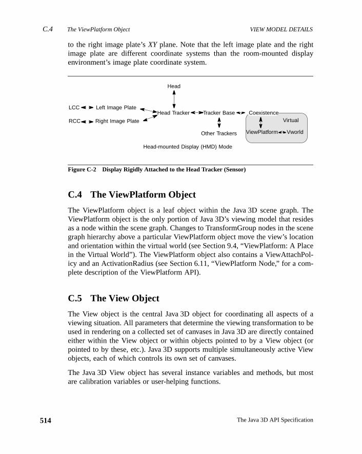
C.4 The ViewPlatform Object VIEW MODEL DETAILS
514
htplay
Theesscenetioncel-m-
f abe
ainedoriew
most
to the right image plate’sXY plane. Note that the left image plate and the rigimage plate are different coordinate systems than the room-mounted disenvironment’s image plate coordinate system.
Figure C-2 Display Rigidly Attached to the Head Tracker (Sensor)
C.4 The ViewPlatform Object
The ViewPlatform object is a leaf object within the Java 3D scene graph.ViewPlatform object is the only portion of Java 3D’s viewing model that residas a node within the scene graph. Changes to TransformGroup nodes in thegraph hierarchy above a particular ViewPlatform object move the view’s locaand orientation within the virtual world (see Section 9.4, “ViewPlatform: A Plain the Virtual World”). The ViewPlatform object also contains a ViewAttachPoicy and an ActivationRadius (see Section 6.11, “ViewPlatform Node,” for a coplete description of the ViewPlatform API).
C.5 The View Object
The View object is the central Java 3D object for coordinating all aspects oviewing situation. All parameters that determine the viewing transformation toused in rendering on a collected set of canvases in Java 3D are directly conteither within the View object or within objects pointed to by a View object (pointed to by these, etc.). Java 3D supports multiple simultaneously active Vobjects, each of which controls its own set of canvases.
The Java 3D View object has several instance variables and methods, butare calibration variables or user-helping functions.
Left Image Plate
Head
LCC
RCC Right Image Plate
Head Tracker
Head-mounted Display (HMD) Mode
Tracker Base
Other Trackers
Coexistence
ViewPlatform
Virtual
Vworld
The Java 3D API Specification
VIEW MODEL DETAILS View Policy C.5.1
f six-
Thisrans-ad-
user-
thesfor-
Theew
intsbasedjec-
Methods
public void setTrackingEnable(boolean flag)public boolean getTrackingEnable()
These methods set and retrieve a flag specifying whether to enable the use odegrees-of-freedom tracking hardware.
public void getUserHeadToVworld(Transform3D t)
This method retrieves the user-head-to-vworld coordinate system transform.Transform3D object takes points in the user’s head coordinate system and tforms them into points in the virtual world coordinate system. This value is reonly. Java 3D continually generates it, but only if enabled by using thesetUser-
HeadToVworldEnable method.
public void setUserHeadToVworldEnable(boolean flag)public boolean getUserHeadToVworldEnable()
These methods set and retrieve a flag that specifies whether to generate thehead-to-vworld transform (initiallyfalse) repeatedly.
public String toString()
This method returns a string that contains the values of this View object.
C.5.1 View Policy
The view policy informs Java 3D whether it should generate the view usinghead-tracked system of transformations or the head-mounted system of tranmations. These policies are attached to the Java 3D View object.
Methods
public void setViewPolicy(int policy)public int getViewPolicy()
These two methods set and retrieve the current policy for view computation.policy variable specifies how Java 3D uses its transforms in computing nviewpoints, as follows:
• SCREEN_VIEW: Specifies that Java 3D should compute new viewpousing the sequence of transforms appropriate to nonattached, screen-head-tracked display environments, such as fishtank VR, multiple-protion walls, and VR desks. This is the default setting.
515Version 1.2, April 2000
C.5.2 Screen Scale Policy VIEW MODEL DETAILS
516
s-nvi-e
olicy
ser-
romult
when
on-on
Thet can
isifiedli-
• HMD_VIEW: Specifies that Java 3D should compute new viewpoints uing the sequence of transforms appropriate to head-mounted display eronments. This policy is not available in compatibility mode (seSection C.11, “Compatibility Mode”).
C.5.2 Screen Scale Policy
The screen scale policy specifies where the screen scale comes from. The pcan be one of the following:
• SCALE_EXPLICIT: Specifies that the screen scale is taken from the uprovidedscreenScale attribute.
• SCALE_SCREEN_SIZE: Specifies that the screen scale is derived fthe physical screen according to the following formula. This is the defapolicy.
screenScale = physicalScreenWidth / 2.0
public void setScreenScalePolicy(int policy)public int getScreenScalePolicy()
These methods set and retrieve the current screen scale policy.
public void setScreenScale(double scale)public double getScreenScale()
These methods set and retrieve the screen scale value. This value is usedthe screen scale policy isSCALE_EXPLICIT.
C.5.3 Window Eyepoint Policy
The window eyepoint policy comes into effect in a non-head-tracked envirment. The policy tells Java 3D how to construct a new view frustum basedchanges in the field of view and in the Canvas3D’s location on the screen.policy comes into effect only when the application changes a parameter thachange the placement of the eyepoint relative to the view frustum.
Constants
public static final int RELATIVE_TO_FIELD_OF_VIEW
This variable tells Java 3D that it should modify the eyepoint position so itlocated at the appropriate place relative to the window to match the specfield of view. This implies that the view frustum will change whenever the app
The Java 3D API Specification
VIEW MODEL DETAILS Monoscopic View PolicyC.5.4
his
tirea 3Dthatof a
ma-es ativeere
w is
n int iseach
the
ead-
ew in 1.2
cation changes the field of view. In this mode, the eye position is read-only. Tis the default setting.
public static final int RELATIVE_TO_SCREEN
This variable tells Java 3D to interpret the eye’s position relative to the enscreen. No matter where an end user moves a window (a Canvas3D), Javcontinues to interpret the eye’s position relative to the screen. This impliesthe view frustum changes shape whenever an end user moves the locationwindow on the screen. In this mode, the field of view is read-only.
public static final int RELATIVE_TO_WINDOW
This variable specifies that Java 3D should interpret the eye’s position infortion relative to the window (Canvas3D). No matter where an end user movwindow (a Canvas3D), Java 3D continues to interpret the eye’s position relato that window. This implies that the frustum remains the same no matter whthe end user moves the window on the screen. In this mode, the field of vieread-only.
public static final int RELATIVE_TO_COEXISTENCE
This variable specifies that Java 3D should interpret the fixed eyepoint positiothe view as relative to the origin of coexistence coordinates. This eyepointransformed from coexistence coordinates to image plate coordinates forCanvas3D. As inRELATIVE_TO_SCREEN mode, this implies that the view frustumshape will change whenever a user moves the location of a window onscreen.
Methods
public int getWindowEyepointPolicy()public void setWindowEyepointPolicy(int policy)
This variable specifies how Java 3D handles the predefined eyepoint in a non-htracked application. The variable can contain one of four values:RELATIVE_TO_
FIELD_OF_VIEW, RELATIVE_TO_SCREEN, RELATIVE_TO_WINDOW, or RELATIVE_TO_COEXISTENCE. The default value isRELATIVE_TO_FIELD_OF_VIEW.
C.5.4 Monoscopic View Policy
This policy specifies how Java 3D generates a monoscopic view.
N
517Version 1.2, April 2000
C.5.5 Visibility Policy VIEW MODEL DETAILS
518
ifiessec-from
e theleft
fiespec-oth
be
New in 1.2
New in 1.2
New in 1.2
New in 1.2
New in 1.2
New in 1.2
New in 1.2
Constants
public static final int LEFT_EYE_VIEWpublic static final int RIGHT_EYE_VIEWpublic static final int CYCLOPEAN_EYE_VIEW
These constants specify the monoscopic view policy. The first constant specthat the monoscopic view should be the view as seen from the left eye. Theond constant specifies that the monoscopic view should be the view as seenthe right eye. The third constant specifies that the monoscopic view should bview as seen from the “center eye,” the fictional eye half-way between theand right eyes. This is the default setting.
Methods
public void setMonoscopicViewPolicy(int policy)public int getMonoscopicViewPolicy()
These methods are deprecated. Use theCanvas3D.setMonoscopicViewPolicy
andCanvas3D.getMonoscopicViewPolicy methods.
C.5.5 Visibility Policy
This policy specifies how visible and invisible objects are drawn.
Constants
public static final int VISIBILITY_DRAW_VISIBLEpublic static final int VISIBILITY_DRAW_INVISIBLEpublic static final int VISIBILITY_DRAW_ALL
These constants set the visibility policy for this view. The first constant specithat only visible objects are drawn (this is the default). The second constant sifies that only invisible objects are drawn. The third constant specifies that bvisible and invisible objects are drawn.
Methods
public void setVisibilityPolicy(int policy)public int getVisibilityPolicy()
These methods set and retrieve the visibility policy for this view. The policy canone ofVISIBILITY_DRAW_VISIBLE, VISIBILITY_DRAW_INVISIBLE, or VISIBIL-ITY_DRAW_ALL. The default visibility policy isVISIBILITY_DRAW_VISIBLE.
The Java 3D API Specification
VIEW MODEL DETAILS Sensors and Their Location in the Virtual WorldC.5.8
coex-ordi-to theding
ker-ntityg isInP-
es inheadinde or
worldsen-tes.vir-
ew in 1.2
ew in 1.2
ew in 1.2
ew in 1.2
ew in 1.2
ew in 1.2
C.5.6 Coexistence Centering Enable
public void setCoexistenceCenteringEnable(boolean flag)public boolean getCoexistenceCenteringEnable()
These methods set and retrieve the coexistenceCentering enable flag. If theistenceCentering flag is true, the center of coexistence in image plate conates, as specified by the trackerBaseToImagePlate transform, is translatedcenter of either the window or the screen in image plate coordinates, accorto the value of windowMovementPolicy.
By default, coexistenceCentering is enabled. It should be disabled if the tracBaseToImagePlate calibration transform is set to a value other than the ide(for example, when rendering to multiple screens or when head trackinenabled). This flag is ignored for HMD mode or when the coexistenceCenterworldPolicy isnot NOMINAL_SCREEN.
C.5.7 Eyepoint in Coexistence
public void setLeftManualEyeInCoexistence(Point3d position)public void setRightManualEyeInCoexistence(Point3d position)public void getLeftManualEyeInCoexistence(Point3d position)public void getRightManualEyeInCoexistence(Point3d position)
These methods set and retrieve the position of the manual right and left eycoexistence coordinates. These values determine eye placement when atracker is not in use and the application is directly controlling the eye positioncoexistence coordinates. These values are ignored when in head-tracked mowhen the windowEyepointPolicy isnot RELATIVE_TO_COEXISTENCE.
C.5.8 Sensors and Their Location in the Virtual World
public void getSensorToVworld(Sensor sensor, Transform3D t)public void getSensorHotSpotInVworld(Sensor sensor, Point3d position)public void getSensorHotSpotInVworld(Sensor sensor, Point3f position)
The first method takes the sensor’s last reading and generates a sensor-to-vcoordinate system transform. This Transform3D object takes points in thatsor’s local coordinate system and transforms them into virtual world coordinaThe next two methods retrieve the specified sensor’s last hotspot location intual world coordinates.
N
N
N
N
N
N
519Version 1.2, April 2000
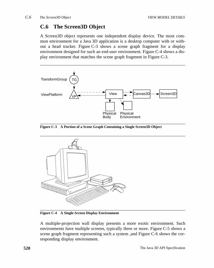
C.6 The Screen3D Object VIEW MODEL DETAILS
520
com-ith-playdis-
chws ae cor-
C.6 The Screen3D Object
A Screen3D object represents one independent display device. The mostmon environment for a Java 3D application is a desktop computer with or wout a head tracker. Figure C-3 shows a scene graph fragment for a disenvironment designed for such an end-user environment. Figure C-4 shows aplay environment that matches the scene graph fragment in Figure C-3.
Figure C-3 A Portion of a Scene Graph Containing a Single Screen3D Object
Figure C-4 A Single-Screen Display Environment
A multiple-projection wall display presents a more exotic environment. Suenvironments have multiple screens, typically three or more. Figure C-5 shoscene graph fragment representing such a system ,and Figure C-6 shows thresponding display environment.
TransformGroup
ViewPlatform
TG
VP
PhysicalBody
PhysicalEnvironment
View Screen3DCanvas3D
The Java 3D API Specification
VIEW MODEL DETAILS Screen3D Calibration ParametersC.6.1
ndwithoex-
9.8,gramthodsers.
Figure C-5 A Portion of a Scene Graph Containing Three Screen3D Objects
Figure C-6 A Three-Screen Display Environment
A multiple-screen environment requires more care during the initialization acalibration phase. Java 3D must know how the Screen3Ds are placedrespect to one another, the tracking device, and the physical portion of the cistence coordinate system.
C.6.1 Screen3D Calibration Parameters
The Screen3D object is the 3D version of AWT’s screen object (see Section“The Screen3D Object”). To use a Java 3D system, someone or some promust calibrate the Screen3D object with the coexistence volume. These meallow that person or program to inform Java 3D of those calibration paramet
TransformGroup
ViewPlatform
TG
VP View
Screen3DCanvas3D
Screen3DCanvas3D
Screen3DCanvas3D
PhysicalBody
PhysicalEnvironment
521Version 1.2, April 2000
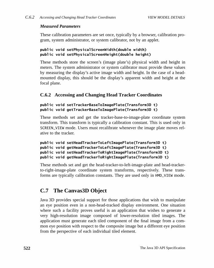
C.6.2 Accessing and Changing Head Tracker Coordinates VIEW MODEL DETAILS
522
pro-
ht inaluesead-the
ysteminrel-
acker-ans-
lateationte aheom-ition
Measured Parameters
These calibration parameters are set once, typically by a browser, calibrationgram, system administrator, or system calibrator, not by an applet.
public void setPhysicalScreenWidth(double width)public void setPhysicalScreenHeight(double height)
These methods store the screen’s (image plate’s) physical width and heigmeters. The system administrator or system calibrator must provide these vby measuring the display’s active image width and height. In the case of a hmounted display, this should be the display’s apparent width and height atfocal plane.
C.6.2 Accessing and Changing Head Tracker Coordinates
public void setTrackerBaseToImagePlate(Transform3D t)public void getTrackerBaseToImagePlate(Transform3D t)
These methods set and get the tracker-base-to-image-plate coordinate stransform. This transform is typically a calibration constant. This is used onlySCREEN_VIEW mode. Users must recalibrate whenever the image plate movesative to the tracker.
public void setHeadTrackerToLeftImagePlate(Transform3D t)public void getHeadTrackerToLeftImagePlate(Transform3D t)public void setHeadTrackerToRightImagePlate(Transform3D t)public void getHeadTrackerToRightImagePlate(Transform3D t)
These methods set and get the head-tracker-to-left-image-plate and head-trto-right-image-plate coordinate system transforms, respectively. These trforms are typically calibration constants. They are used only inHMD_VIEW mode.
C.7 The Canvas3D Object
Java 3D provides special support for those applications that wish to manipuan eye position even in a non-head-tracked display environment. One situwhere such a facility proves useful is an application that wishes to generavery high-resolution image composed of lower-resolution tiled images. Tapplication must generate each tiled component of the final image from a cmon eye position with respect to the composite image but a different eye posfrom the perspective of each individual tiled element.
The Java 3D API Specification
VIEW MODEL DETAILS Accessing and Modifying an Eye’s Image Plate PositionC.7.2
vail-
ye’s. Itage
es inheadin
nterTheese
age
ew in 1.2
C.7.1 Scene Antialiasing
public boolean getSceneAntialiasingAvailable()
This method returns a status flag indicating whether scene antialiasing is aable.
C.7.2 Accessing and Modifying an Eye’s Image Plate Position
A Canvas3D object provides sophisticated applications with access to the eposition information in head-tracked, room-mounted runtime environmentsalso allows applications to manipulate the position of an eye relative to an implate in non-head-tracked runtime environments.
public void setLeftManualEyeInImagePlate(Point3d position)public void setRightManualEyeInImagePlate(Point3d position)public void getLeftManualEyeInImagePlate(Point3d position)public void getRightManualEyeInImagePlate(Point3d position)
These methods set and retrieve the position of the manual left and right eyimage plate coordinates. These values determine eye placement when atracker is not in use and the application is directly controlling the eye positionimage plate coordinates. In head-tracked mode or when thewindowEyepoint-
Policy is RELATIVE_TO_FIELD_OF_VIEW or RELATIVE_TO_COEXISTENCE, thisvalue is ignored. When thewindowEyepointPolicy is RELATIVE_TO_WINDOW,only theZ value is used.
public void getLeftEyeInImagePlate(Point3d position)public void getRightEyeInImagePlate(Point3d position)public void getCenterEyeInImagePlate(Point3d position)
These methods retrieve the actual position of the left eye, right eye, and ceeye in image plate coordinates and copy that value into the object provided.center eye is the fictional eye half-way between the left and right eye. Ththree values are a function of thewindowEyepointPolicy; the tracking enableflag, and the manual left, right, and center eye positions.
public void getPixelLocationInImagePlate(int x, int y, Point3d imagePlatePoint)public void getPixelLocationInImagePlate(Point2d pixelLocation, Point3d imagePlatePoint)
These methods compute the position of the specified AWT pixel value in implate coordinates and copy that value into the object provided.
N
523Version 1.2, April 2000
C.7.3 Canvas Width and Height VIEW MODEL DETAILS
524
WTro-
tem
tem
, in
rates
eye.wand
its
New in 1.2
New in 1.2
New in 1.2
public void getPixelLocationFromImagePlate(Point3d imagePlatePoint, Point2d pixelLocation)
This method projects the specified point from image plate coordinates into Apixel coordinates. The AWT pixel coordinates are copied into the object pvided.
public void getVworldToImagePlate(Transform3D t)
This method retrieves the current virtual-world-to-image-plate coordinate systransform and places it into the specified object.
public void getImagePlateToVworld(Transform3D t)
This method retrieves the current image-plate-to-virtual-world coordinate systransform and places it into the specified object.
C.7.3 Canvas Width and Height
public double getPhysicalWidth()public double getPhysicalHeight()
These methods retrieve the physical width and height of this canvas windowmeters.
C.7.4 Monoscopic View Policy
public void setMonoscopicViewPolicy(int policy)public int getMonoscopicViewPolicy()
These methods set and retrieve the policy regarding how Java 3D genemonoscopic view. If the policy is set toView.LEFT_EYE_VIEW, the view gener-ated corresponds to the view as seen from the left eye. If set toView.RIGHT_
EYE_VIEW, the view generated corresponds to the view as seen from the rightIf set toView.CYCLOPEAN_EYE_VIEW, the view generated corresponds to the vieas seen from the “center eye,” the fictional eye half-way between the leftright eye. The default monoscopic view policy isView.CYCLOPEAN_EYE_VIEW.
Note: For backward compatibility with Java 3D 1.1, if this attribute is set todefault value ofView.CYCLOPEAN_EYE_VIEW, the monoscopic view policy in theView object will be used. An application should not use both the deprecatedView
method and thisCanvas3D method at the same time.
The Java 3D API Specification
VIEW MODEL DETAILS The PhysicalBody Object C.8
cter-ecifyn soeadistentthus
ym-ad
and
d ear
C.8 The PhysicalBody Object
The PhysicalBody object contains information concerning the physical charaistics of the end-user’s body. The head parameters allow end users to sptheir own heads’ characteristics and thus to customize any Java 3D applicatiothat it conforms to their unique geometry. The PhysicalBody object defines hparameters in the head coordinate system. It provides a simple and conscoordinate frame for specifying such factors as the location of the eyes andthe interpupilary distance.
The Head Coordinate System
The head coordinate system has its origin on the head’s bilateral plane of smetry, roughly half-way between the left and right eyes. The origin of the hecoordinate system is known as thecenter eye. The positiveX-axis extends to theright. The positiveY-axis extends up. The positiveZ-axis extends into the skull.Values are in meters.
Constructors
public PhysicalBody()
Constructs a default user PhysicalBody object with the following default eyeear positions:
public PhysicalBody(Point3d leftEyePosition, Point3d rightEyePosition)public PhysicalBody(Point3d leftEyePosition, Point3d rightEyePosition, Point3d leftEarPosition, Point3d rightEarPosition)
These methods construct a PhysicalBody object with the specified eye anpositions.
Parameter Default Value
leftEyePosition (–0.033, 0.0, 0.0)
rightEyePosition (0.033, 0.0, 0.0)
leftEarPosition (–0.080, –0.030, 0.095)
rightEarPosition (0.080, –0.030, 0.095)
nominalEyeHeightFromGround 1.68
nominalEyeOffsetFromNominalScreen 0.4572
headToHeadTracker identity
525Version 1.2, April 2000
C.8 The PhysicalBody Object VIEW MODEL DETAILS
526
ser’s
posi-
fromoni-
tionture
of thethe
trans-eadboth
ject.
Methods
public void getLeftEyePosition(Point3d position)public void setLeftEyePosition(Point3d position)public void getRightEyePosition(Point3d position)public void setRightEyePosition(Point3d position)
These methods set and retrieve the position of the center of rotation of a uleft and right eyes in head coordinates.
public void getLeftEarPosition(Point3d position)public void setLeftEarPosition(Point3d position)public void getRightEarPosition(Point3d position)public void setRightEarPosition(Point3d position)
These methods set and retrieve the position of the user’s left and right eartions in head coordinates.
public double getNominalEyeHeightFromGround()public void setNominalEyeHeightFromGround(double height)
These methods set and retrieve the user’s nominal eye height as measuredthe ground to the center eye in the default posture. In a standard computer mtor environment, the default posture would be seated. In a multiple-projecdisplay room environment or a head-tracked environment, the default poswould be standing.
public double getNominalEyeOffsetFromNominalScreen()public void setNominalEyeOffsetFromNominalScreen(double offset)
These methods set and retrieve the offset from the center eye to the centerdisplay screen. This offset distance allows an “over the shoulder” view ofscene as seen by the end user.
public void setHeadToHeadTracker(Transform3D t)public void getHeadToHeadTracker(Transform t)
These methods set and retrieve the head-to-head-tracker coordinate systemform. If head tracking is enabled, this transform is a calibration constant. If htracking is not enabled, this transform is not used. This transform is used inSCREEN_VIEW andHMD_VIEW modes.
public String toString()
This method returns a string that contains the values of this PhysicalBody ob
The Java 3D API Specification
VIEW MODEL DETAILS The PhysicalEnvironment Object C.9
icalout
ing
icesstick,” forousg”).
ro-viceforore
C.9 The PhysicalEnvironment Object
The PhysicalEnvironment object contains information about the local physworld of the end-user’s physical environment. This includes information abaudio output devices and tracking sensor hardware, if present.
Constructors
public PhysicalEnvironment()
Constructs and initializes a new PhysicalEnvironment object with the followdefault parameters:
public PhysicalEnvironment(int sensorCount)
Constructs and initializes a new PhysicalEnvironment object.
The sensor information provides real-time access to continuous-input devsuch as joysticks and trackers. It also contains two-degrees-of-freedom joyand six-degrees-of-freedom tracker information. See Section 11.2, “Sensorsmore information. Java 3D uses Java AWT’s event model for noncontinuinput devices such as keyboards (see Chapter 11, “Input Devices and Pickin
Audio device information associated with the PhysicalEnvironment object pvides a mechanism that allows the application to choose a particular audio de(if more than one is available) and explicitly set the type of audio playbacksound rendered using this device. See Chapter 12, “Audio Devices,” for m
Parameter Default Value
sensorCount 3
sensors null (for all array elements)
headIndex 0
rightHandIndex 1
leftHandIndex 2
dominantHandIndex 1
nonDominantHandIndex 2
trackingAvailable false
audioDevice null
inputDevice list empty
coexistenceToTrackerBase identity
coexistenceCenterInPworldPolicy View.NOMINAL_SCREEN
527Version 1.2, April 2000
C.9 The PhysicalEnvironment Object VIEW MODEL DETAILS
528
out-
to
ugh
put
ithin. It
ment
sform.ck-
details on the fields and methods that set and initialize the device driver andput playback associated with the audio device.
Methods
The PhysicalEnvironment object specifies the following methods pertainingaudio output devices and input sensors.
public void setAudioDevice(AudioDevice device)
This method selects the specified AudioDevice object as the device throwhich audio rendering for this PhysicalEnvironment will be performed.
public AudioDevice getAudioDevice()
This method retrieves the specified AudioDevice object.
public void addInputDevice(InputDevice device)public void removeInputDevice(InputDevice device)
These methods add and remove an input device to or from the list of indevices.
public Enumeration getAllInputDevices()
This method creates an enumerator that produces all input devices.
public void setSensorCount(int count)public int getSensorCount()
These methods set and retrieve the count of the number of sensors stored wthe PhysicalEnvironment object. It defaults to a small number of sensorsshould be set to the number of sensors available in the end-user’s environbefore initializing the Java 3D API.
public void setCoexistenceToTrackerBase(Transform3D t)public void getCoexistenceToTrackerBase(Transform3D t)
These methods set the coexistence-to-tracker-base coordinate system tranIf head tracking is enabled, this transform is a calibration constant. If head traing is not enabled, this transform is not used. This is used in bothSCREEN_VIEW
andHMD_VIEW modes.
public boolean getTrackingAvailable()
This method returns a status flag indicating whether tracking is available.
The Java 3D API Specification
VIEW MODEL DETAILS Viewing in Head-Tracked EnvironmentsC.10
ided.
and.
phys-ye-ss.
for aribeiron-or ahow
public void setSensor(int index, Sensor sensor)public Sensor getSensor(int index)
The first method sets the sensor specified by the index to the sensor provThe second method retrieves the specified sensor.
public void setDominantHandIndex(int index)public int getDominantHandIndex()
These methods set and retrieve the index of the dominant hand.
public void setNonDominantHandIndex(int index)public int getNonDominantHandIndex()
These methods set and retrieve the index of the nondominant hand.
public void setHeadIndex(int index)public int getHeadIndex()public void setRightHandIndex(int index)public int getRightHandIndex()public void setLeftHandIndex(int index)public int getLeftHandIndex()
These methods set and retrieve the index of the head, right hand, and left hTheindex parameter refers to the sensor index.
Physical Coexistence Policy
public int getCoexistenceCenterInPworldPolicy()public void setCoexistenceCenterInPworldPolicy(int policy)
These methods set and retrieve the physical coexistence policy used in thisical environment. This policy specifies how Java 3D will place the user’s epoint as a function of current head position during the calibration proceJava 3D permits one of three values:NOMINAL_HEAD, NOMINAL_FEET, or NOMINAL_SCREEN.
C.10 Viewing in Head-Tracked Environments
Section 9.5, “Generating a View,” describes how Java 3D generates a viewstandard flat-screen display with no head tracking. In this section, we deschow Java 3D generates a view in a room-mounted, head-tracked display envment—either a computer monitor with shutter glasses and head trackingmultiple-wall display with head-tracked shutter glasses. Finally, we describe
529Version 1.2, April 2000
C.10.1 A Room-Mounted Display with Head Tracking VIEW MODEL DETAILS
530
isplay
(fornta-3D
user’sorre-
e’stivewillter-end-
lsocked,n anda
o notmoverad-heonoesplay
esult.
e inces
thehoseori-
Java 3D generates view matrices in a head-mounted and head-tracked denvironment.
C.10.1 A Room-Mounted Display with Head Tracking
When head tracking combines with a room-mounted display environmentexample, a standard flat-screen display), the ViewPlatform’s origin and orietion serve as a base for constructing the view matrices. Additionally, Javauses the end-user’s head position and orientation to compute where an end-eyes are located in physical space. Each eye’s position serves to offset the csponding virtual eye’s position relative to the ViewPlatform’s origin. Each eyposition also serves to specify that eye’s frustum since the eye’s position relato a Screen3D uniquely specifies that eye’s view frustum. Note that Java 3Daccess the PhysicalBody object to obtain information describing the user’s inpupilary distance and tracking hardware, values it needs to compute theuser’s eye positions from the head position information.
C.10.2 A Head-Mounted Display with Head Tracking
In a head-mounted environment, the ViewPlatform’s origin and orientation aserves as a base for constructing view matrices. And, as in the head-traroom-mounted environment, Java 3D also uses the end-user’s head positioorientation to modify the ViewPlatform’s position and orientation further. Inhead-tracked, head-mounted display environment, an end-user’s eyes dmove relative to their respective display screens, rather, the display screensrelative to the virtual environment. A rotation of the head by an end user canically affect the final view’s orientation. In this situation, Java 3D combines tposition and orientation from the ViewPlatform with the position and orientatifrom the head tracker to form the view matrix. The view frustum, however, dnot change since the user’s eyes do not move relative to their respective disscreen, so Java 3D can compute the projection matrix once and cache the r
If any of the parameters of a View object are updated, this will effect a changthe implicit viewing transform (and thus image) of any Canvas3D that referenthat View object.
C.11 Compatibility Mode
A camera-based view model allows application programmers to think aboutimages displayed on the computer screen as if a virtual camera took timages. Such a view model allows application programmers to position and
The Java 3D API Specification
VIEW MODEL DETAILS Overview of the Camera-Based View ModelC.11.1
f theof
ed,sing
in
by
’sods
tualiewtemthe
on,.
ecifyatedhedis-frus-ies.
ithtings,stumping
ent a virtual camera within a virtual scene, to manipulate some parameters ovirtual camera’s lens (specify its field of view), and to specify the locationsthe near and far clipping planes.
Java 3D allows applications to enable compatibility mode for room-mountnon-head-tracked display environments or to disable compatibility mode uthe following methods. Camera-based viewing functions are available onlycompatibility mode.
Methods
public void setCompatibilityModeEnable(boolean flag)public boolean getCompatabilityModeEnable()
This flag turns compatibility mode on or off. Compatibility mode is disableddefault.
Note: Use of these view-compatibility functions will disable some of Java 3Dview model features and limit the portability of Java 3D programs. These methare primarily intended to help jump-start porting of existing applications.
C.11.1 Overview of the Camera-Based View Model
The traditional camera-based view model, shown in Figure C-7, places a vircamera inside a geometrically specified world. The camera “captures” the vfrom its current location, orientation, and perspective. The visualization systhen draws that view on the user’s display device. The application controlsview by moving the virtual camera to a new location, by changing its orientatiby changing its field of view, or by controlling some other camera parameter
The various parameters that users control in a camera-based view model spthe shape of a viewing volume (known as a frustum because of its truncpyramidal shape) and locate that frustum within the virtual environment. Trendering pipeline uses the frustum to decide which objects to draw on theplay screen. The rendering pipeline does not draw objects outside the viewtum, and it clips (partially draws) objects that intersect the frustum’s boundar
Though a view frustum’s specification may have many items in common wthose of a physical camera, such as placement, orientation, and lens setsome frustum parameters have no physical analog. Most noticeably, a fruhas two parameters not found on a physical camera: the near and far clipplanes.
531Version 1.2, April 2000
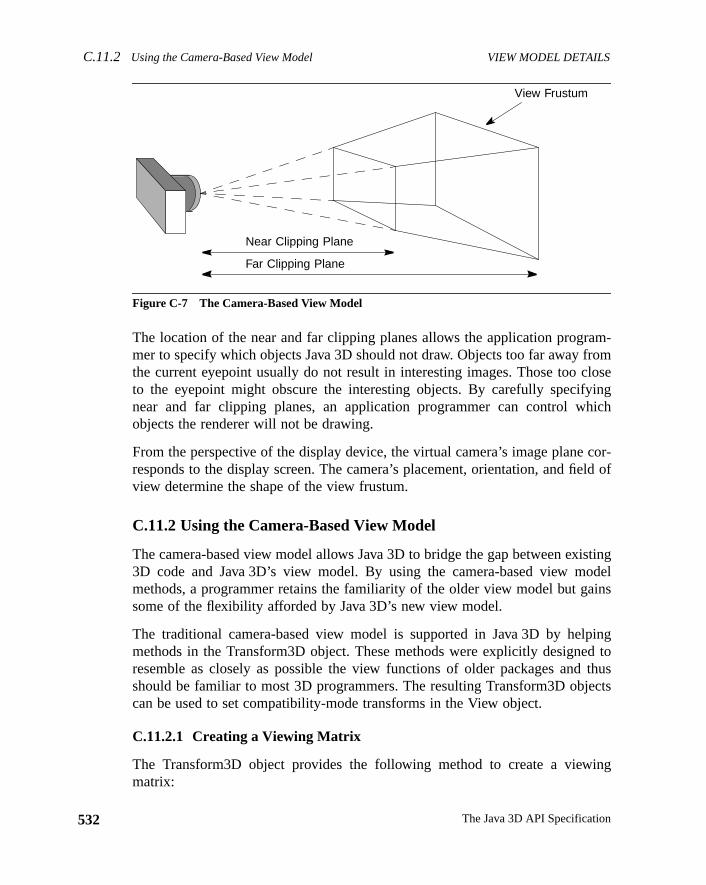
C.11.2 Using the Camera-Based View Model VIEW MODEL DETAILS
532
am-romloseingich
cor-ld of
istingodelins
pingd tothuscts
ing
Figure C-7 The Camera-Based View Model
The location of the near and far clipping planes allows the application progrmer to specify which objects Java 3D should not draw. Objects too far away fthe current eyepoint usually do not result in interesting images. Those too cto the eyepoint might obscure the interesting objects. By carefully specifynear and far clipping planes, an application programmer can control whobjects the renderer will not be drawing.
From the perspective of the display device, the virtual camera’s image planeresponds to the display screen. The camera’s placement, orientation, and fieview determine the shape of the view frustum.
C.11.2 Using the Camera-Based View Model
The camera-based view model allows Java 3D to bridge the gap between ex3D code and Java 3D’s view model. By using the camera-based view mmethods, a programmer retains the familiarity of the older view model but gasome of the flexibility afforded by Java 3D’s new view model.
The traditional camera-based view model is supported in Java 3D by helmethods in the Transform3D object. These methods were explicitly designeresemble as closely as possible the view functions of older packages andshould be familiar to most 3D programmers. The resulting Transform3D objecan be used to set compatibility-mode transforms in the View object.
C.11.2.1 Creating a Viewing Matrix
The Transform3D object provides the following method to create a viewmatrix:
View Frustum
Near Clipping Plane
Far Clipping Plane
The Java 3D API Specification
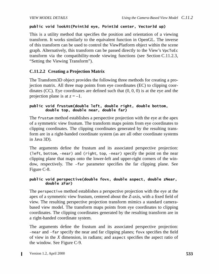
VIEW MODEL DETAILS Using the Camera-Based View ModelC.11.2
ingseene
.3,
ro-or-d the
pexs toans-tems
tion:
in-ee
the
era-pingre in
tion:
f
public void lookAt(Point3d eye, Point3d center, Vector3d up)
This is a utility method that specifies the position and orientation of a viewtransform. It works similarly to the equivalent function in OpenGL. The inverof this transform can be used to control the ViewPlatform object within the scgraph. Alternatively, this transform can be passed directly to the View’sVpcToEc
transform via the compatibility-mode viewing functions (see Section C.11.2“Setting the Viewing Transform”).
C.11.2.2 Creating a Projection Matrix
The Transform3D object provides the following three methods for creating a pjection matrix. All three map points from eye coordinates (EC) to clipping codinates (CC). Eye coordinates are defined such that (0, 0, 0) is at the eye anprojection plane is atz = –1.
public void frustum(double left, double right, double bottom, double top, double near, double far)
Thefrustum method establishes a perspective projection with the eye at the aof a symmetric view frustum. The transform maps points from eye coordinateclipping coordinates. The clipping coordinates generated by the resulting trform are in a right-handed coordinate system (as are all other coordinate sysin Java 3D).
The arguments define the frustum and its associated perspective projec(left, bottom, -near) and(right, top, -near) specify the point on the nearclipping plane that maps onto the lower-left and upper-right corners of the wdow, respectively. The-far parameter specifies the far clipping plane. SFigure C-8.
public void perspective(double fovx, double aspect, double zNear, double zFar)
Theperspective method establishes a perspective projection with the eye atapex of a symmetric view frustum, centered about theZ-axis, with a fixed field ofview. The resulting perspective projection transform mimics a standard cambased view model. The transform maps points from eye coordinates to clipcoordinates. The clipping coordinates generated by the resulting transform aa right-handed coordinate system.
The arguments define the frustum and its associated perspective projec-near and-far specify the near and far clipping planes;fovx specifies the fieldof view in theX dimension, in radians; andaspect specifies the aspect ratio othe window. See Figure C-9.
533Version 1.2, April 2000
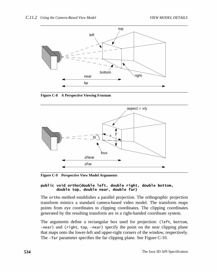
C.11.2 Using the Camera-Based View Model VIEW MODEL DETAILS
534
tionaps
tes.
eely.
Figure C-8 A Perspective Viewing Frustum
Figure C-9 Perspective View Model Arguments
public void ortho(double left, double right, double bottom, double top, double near, double far)
The ortho method establishes a parallel projection. The orthographic projectransform mimics a standard camera-based video model. The transform mpoints from eye coordinates to clipping coordinates. The clipping coordinagenerated by the resulting transform are in a right-handed coordinate system
The arguments define a rectangular box used for projection:(left, bottom,-near) and (right, top, -near) specify the point on the near clipping planthat maps onto the lower-left and upper-right corners of the window, respectivThe-far parameter specifies the far clipping plane. See Figure C-10.
near
far
left
top
bottomright
zNear
zFar
fovx
x yΘ
aspect = x/y
The Java 3D API Specification
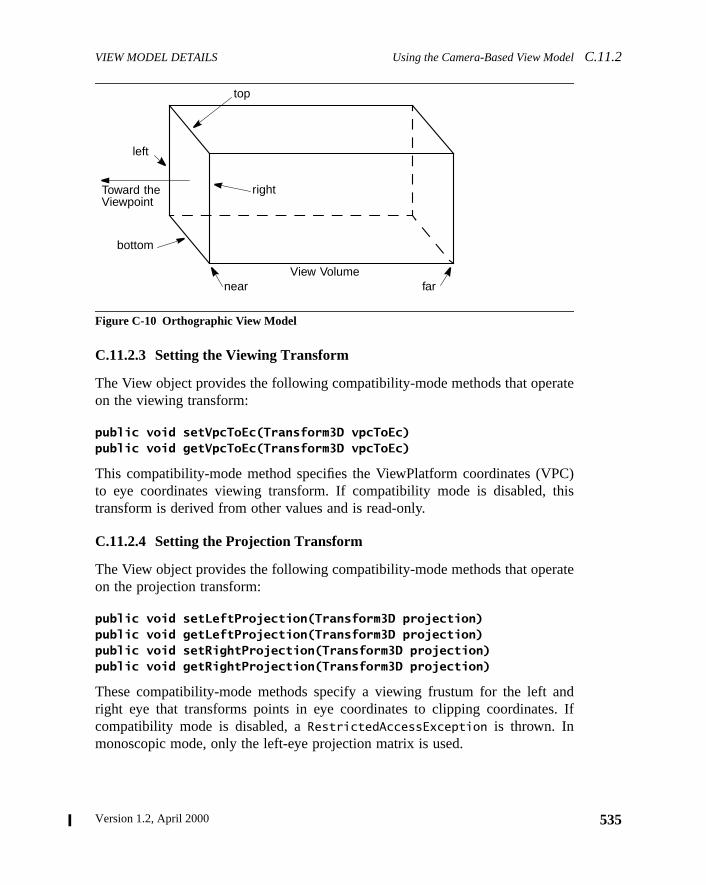
VIEW MODEL DETAILS Using the Camera-Based View ModelC.11.2
ate
C)his
ate
nd. If
Figure C-10 Orthographic View Model
C.11.2.3 Setting the Viewing Transform
The View object provides the following compatibility-mode methods that operon the viewing transform:
public void setVpcToEc(Transform3D vpcToEc)public void getVpcToEc(Transform3D vpcToEc)
This compatibility-mode method specifies the ViewPlatform coordinates (VPto eye coordinates viewing transform. If compatibility mode is disabled, ttransform is derived from other values and is read-only.
C.11.2.4 Setting the Projection Transform
The View object provides the following compatibility-mode methods that operon the projection transform:
public void setLeftProjection(Transform3D projection)public void getLeftProjection(Transform3D projection)public void setRightProjection(Transform3D projection)public void getRightProjection(Transform3D projection)
These compatibility-mode methods specify a viewing frustum for the left aright eye that transforms points in eye coordinates to clipping coordinatescompatibility mode is disabled, aRestrictedAccessException is thrown. Inmonoscopic mode, only the left-eye projection matrix is used.
left
top
bottom
Toward theViewpoint
right
nearView Volume
far
535Version 1.2, April 2000

Version 1.2, April 2000
A P P E N D I X D
rrorsh as
riousn of
eonss.
the
oupor a
ectlat-ear
tain
Exceptions
THE Java 3D API uses the standard Java exception model for handling eor exceptional conditions. In addition to using existing exception classes, sucArrayIndexOutOfBoundsException and IllegalArgumentException, Java 3Ddefines several new runtime exceptions. These exceptions are thrown by vaJava 3D methods or by the Java 3D renderer to indicate an error conditiosome kind.
The exceptions defined by Java 3D, as part of thejavax.media.j3d package, aredescribed in the following sections. They all extendRuntimeException and, assuch, need not be declared in thethrows clause of methods that might cause thexception to be thrown. This appendix is not an exhaustive list of all exceptiexpected for Java 3D. Additional exceptions will be added as the need arise
D.1 BadTransformException
Indicates an attempt to use a Tranform3D object that is inappropriate forobject in which it is being used. For example,
• Transforms that are used in the scene graph, within a TransformGrnode, must be affine. They may optionally contain a nonuniform scaleshear, subject to other listed restrictions.
• All transforms in the TransformGroup nodes above a ViewPlatform objmust be congruent. This ensures that the Vworld-coordinates-to-ViewPform-coordinates transform is angle- and length-preserving with no shand with uniform scale. only
• Most viewing transforms other than those in the scene graph can contranslation and rotation only.
537
D.2 CapabilityNotSetException EXCEPTIONS
538
r a
e firstring to
bject
e firstring to
sph isncetwo
• The projection transform is allowed to be nonaffine, but it must be eithesingle-point perspective projection or a parallel projection.
Constructors
public BadTransformException()public BadTransformException(String str)
These create the exception object that outputs the exception message. Thform uses the default message. The second form specifies the message stbe output.
D.2 CapabilityNotSetException
This exception indicates an access to a live or compiled Scene Graph owithout the required capability set.
Constructors
public CapabilityNotSetException()public CapabilityNotSetException(String str)
These create the exception object that outputs the exception message. Thform uses the default message. The second form specifies the message stbe output.
D.3 DanglingReferenceException
This exception indicates that during acloneTree call, an updated reference warequested for a node that did not get cloned. This occurs when a subgraduplicated viacloneTree and has at least one leaf node that contains a refereto a node with no corresponding node in the cloned subgraph. This results inleaf nodes wanting to share access to the same node.
If dangling references are to be allowed during thecloneTree call, cloneTreeshould be called with theallowDanglingReferences parameter set totrue.
The Java 3D API Specification
EXCEPTIONS IllegalSharingException D.5
e firstring to
e firstring to
. For
me-
.
ys:
nd
Constructors
public DanglingReferenceException()public DanglingReferenceException(String str)
These create the exception object that outputs the exception message. Thform uses the default message. The second form specifies the message stbe output.
D.4 IllegalRenderingStateException
This exception indicates an illegal state for rendering. It is currently unused.
public illegalRenderingStateException()public illegalRenderingStateException(String str)
These create the exception object that outputs the exception message. Thform uses the default message. The second form specifies the message stbe output.
D.5 IllegalSharingException
This exception indicates an illegal attempt to share a scene graph objectexample, the following are illegal:
• Referencing a shared subgraph in more than one virtual universe.
• Using the same component object both in the scene graph and in an imdiate-mode graphics context.
• Including an unsupported type of leaf node within a shared subgraph
• Referencing a BranchGroup node in more than one of the following wa• Attaching it to a (single) Locale.
• Adding it as a child of a Group node within the scene graph.
• Referencing it from a (single) Background leaf node as backgrougeometry.
Constructors
public IllegalSharingException()public IllegalSharingException(String str)
539Version 1.2, April 2000
D.6 MismatchedSizeException EXCEPTIONS
540
e firstring to
ause
e firstring to
e.
e firstring to
houtt
These create the exception object that outputs the exception message. Thform uses the default message. The second form specifies the message stbe output.
D.6 MismatchedSizeException
This exception indicates that an operation cannot be completed properly becof a mismatch in the sizes of the object attributes.
public MismatchedSizeException()public MismatchedSizeException(String str)
These create the exception object that outputs the exception message. Thform uses the default message. The second form specifies the message stbe output.
D.7 MultipleParentException
This exception extendsIllegalSharingException and indicates an attempt toadd a node that is already a child of one group node into another group nod
Constructors
public MultipleParentException()public MultipleParentException(String str)
These create the exception object that outputs the exception message. Thform uses the default message. The second form specifies the message stbe output.
D.8 RestrictedAccessException
This exception indicates an attempt to access or modify a state variable witpermission to do so. For example, invoking aset method for a state variable thais currently read-only.
The Java 3D API Specification
EXCEPTIONS SingularMatrixException D.10
e firstring to
abled, as
erercle is
e firstring to
a
e firstring to
Constructors
public RestrictedAccessException()public RestrictedAccessException(String str)
These create the exception object that outputs the exception message. Thform uses the default message. The second form specifies the message stbe output.
D.9 SceneGraphCycleException
This exception indicates that one of the live scene graphs attached to a viewLocale has a cycle in it. Java 3D scene graphs are directed acyclic graphs ansuch, do not permit cycles. This exception is thrown by the Java 3D rendeither at scene graph traversal time or when a scene graph containing a cymade live (added as a descendant of a Locale object).
Constructors
public SceneGraphCycleException()public SceneGraphCycleException(String str)
These create the exception object that outputs the exception message. Thform uses the default message. The second form specifies the message stbe output.
D.10 SingularMatrixException
This exception, in thejavax.vecmath package, indicates that the inverse ofmatrix cannot be computed.
Constructors
public SingularMatrixException()public SingularMatrixException(String str)
These create the exception object that outputs the exception message. Thform uses the default message. The second form specifies the message stbe output.
541Version 1.2, April 2000
D.11 SoundException EXCEPTIONS
542
e firstring to
D.11 SoundException
This exception indicates a problem in loading or playing a sound sample.
Constructors
public SoundException()public SoundException(String str)
These create the exception object that outputs the exception message. Thform uses the default message. The second form specifies the message stbe output.
The Java 3D API Specification
Version 1.2, April 2000
A P P E N D I X E
and
e
Equations
THIS appendix contains the Java 3D equations for fog, lighting, sound,texture mapping. Many of the equations use the following symbols:
E.1 Fog Equations
The ideal fog equation is
(Eq. E.1)
The fog coefficient,f, is computed differently for linear and exponential fog. Thequation for linear fog is
(Eq. E.2)
The equation for exponential fog is
(Eq. E.3)
The parameters used in the fog equations are
⋅ Multiplication
• Function operator for sound equations;Dot product for all other equations
C = Color of the pixel being fogged
Cf = Fog color
d = Fog density
F = Front fog distance, measured in eye coordinates
C′ C f C f 1 f–( )⋅+⋅=
fB z–B F–-------------=
f e d z⋅–=
543
E.2 Lighting Equations EQUATIONS
544
or-lor
byo.
r-ap-
aceen-
g
Fallbacks and Approximations
1. An implementation may approximate per-pixel fog by calculating the crect fogged color at each vertex and then linearly interpolating this coacross the primitive.
2. An implementation may approximate exponential fog using linear fogcomputing values ofF andB that cause the resulting linear fog ramp tmost closely match the effect of the specified exponential fog function
3. An implementation will ideally perform the fog calculations in eye coodinates, which is an affine space. However, an implementation mayproximate this by performing the fog calculations in a perspective sp(such as device coordinates). As with other approximations, the implemtation should match the specified function as closely as possible.
E.2 Lighting Equations
The ideal lighting equations are
(Eq. E.4)
(Eq. E.5)
(Eq. E.6)
Note: If (Li • N) ≤ 0, thendiffi andspeci are set to 0.
(Eq. E.7)
Note: For directional lights,atteni is set to 1.
(Eq. E.8)
B = Back fog distance, measured in eye coordinates
z = The z-coordinate distance from the eyepoint to the pixel beinfogged, measured in eye coordinates
f = Fog coefficient
Me Ma+ Lci( ) atteni spoti diff i speci+( )⋅ ⋅( )i
Numlt
∑+i
Numamb
∑⋅
diff i Li N•( ) Lci Md⋅ ⋅=
speci Si N•( )shin Lci Ms⋅ ⋅=
atteni 1 Kci K l i di Kqi di2⋅+⋅+( )⁄=
spoti max Li– Di⋅( ) 0,( )expi=
The Java 3D API Specification
EQUATIONS Lighting Equations E.2
gle,
are
fer-ple,ht
andtionmost
Note: If the vertex is outside the spot light cone, as defined by the cutoff anspoti is set to 0. For directional and point lights,spoti is set to 1.
This is a subset of OpenGL in that the Java 3D ambient and directional lightsnot attenuated and only ambient lights contribute to ambient lighting.
The parameters used in the lighting equation are
The per-light values are
Fallbacks and Approximations
1. An implementation may approximate the specular function using a difent power function that produces a similar specular highlight. For examthe PHIGS+ lighting model specifies that the reflection vector (the ligvector reflected about the vertex normal) is dotted with the eye vectorthat this dot product is raised to the specular power. An implementathat uses such a model should map the shininess into an exponent thatclosely matches the effect produced by the ideal equation.
E = Eye vector
Ma = Material ambient color
Md = Material diffuse color
Me = Material emissive color
Ms = Material specular color
N = Vertex normal
shin = Material shininess
di = Distance from vertex to light
Di = Spot light direction
expi = Spot light exponent
Kci = Constant attenuation
Kli = Linear attenuation
Kqi = Quadratic attenuation
Li = Direction from vertex to light
Lci = Light color
Si = Specular half-vector = || (Li + E) ||
545Version 1.2, April 2000
E.3 Sound Equations EQUATIONS
546
maylor.
lu-
ation
ignal.
ctback
ls arener’s
teds andif-
earad
2. Implementations that do not have a separate ambient and diffuse colorfall back to using an ambient intensity as a percentage of the diffuse coThis ambient intensity should be calculated using the following NTSCminance equation:
I = 0.30⋅ Red +0.59⋅ Green +0.11⋅ Blue (Eq. E.9)
E.3 Sound Equations
There are different sets of sound equations, depending on whether the applicuses headphones or speakers.
E.3.1 Headphone Playback Equations
For each sound source, Java 3D calculates a separate left and right output sEach left and right sound image includes differences in theinteraural intensityand aninteraural delay. The calculation results are a set of direct and indire(delayed) sound signals mixed together before being sent to the audio playsystem’s left and right transducers.
E.3.1.1 Interaural Time Difference (Delay)
For each PointSound and ConeSound source, the left and right output signadelayed based on the location of the sound and the orientation of the listehead. The time difference between these two signals is called theinteraural timedifference (ITD). The time delay of a particular sound reaching an ear is affecby the arc the sound must travel around the listener’s head. Java 3D useapproximation of the ITD using a spherical head model. The interaural pathference is calculated based on the following cases:
1. The signal from the sound source to only one of the ears is direct. Thefarther from the sound is shadowed by the listener’s he( ); see Figure E-1.
(Eq. E.10)
where
sinα De 2Dh⁄≥
Ec Vc=
Ef Vt P+=
PDe2
------- π2--- γ α–( )–
=
The Java 3D API Specification
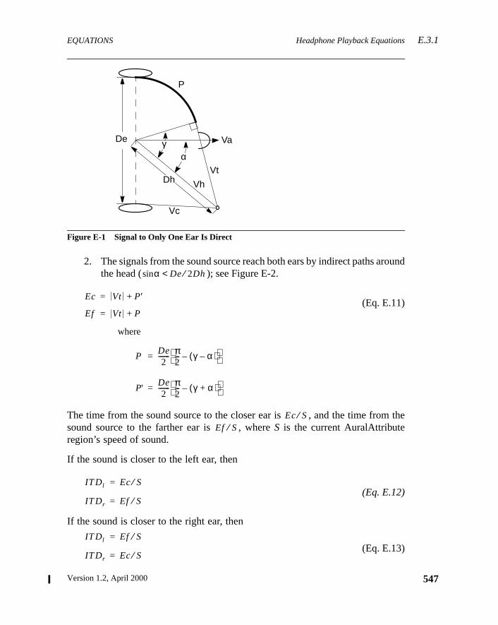
EQUATIONS Headphone Playback EquationsE.3.1
ound
the
Figure E-1 Signal to Only One Ear Is Direct
2. The signals from the sound source reach both ears by indirect paths arthe head ( ); see Figure E-2.
(Eq. E.11)
where
The time from the sound source to the closer ear is , and the time fromsound source to the farther ear is , whereS is the current AuralAttributeregion’s speed of sound.
If the sound is closer to the left ear, then
(Eq. E.12)
If the sound is closer to the right ear, then
(Eq. E.13)
P
Va
Vt
Vh
Vc
Dh
De γα
sinα De 2Dh⁄<
Ec Vt P′+=
Ef Vt P+=
PDe2
------- π2--- γ α–( )–
=
P'De2
------- π2--- γ α+( )–
=
Ec S⁄Ef S⁄
IT Dl Ec S⁄=
IT Dr Ef S⁄=
IT Dl Ef S⁄=
IT Dr Ec S⁄=
547Version 1.2, April 2000
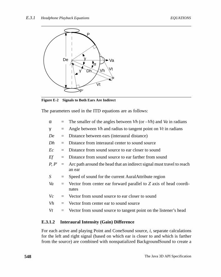
E.3.1 Headphone Playback Equations EQUATIONS
548
herate a
ch
d
Figure E-2 Signals to Both Ears Are Indirect
The parameters used in the ITD equations are as follows:
E.3.1.2 Interaural Intensity (Gain) Difference
For each active and playing Point and ConeSound source,i, separate calculationsfor the left and right signal (based on which ear is closer to and which is fartfrom the source) are combined with nonspatialized BackgroundSound to cre
α = The smaller of the angles betweenVh (or –Vh) andVa in radians
γ = Angle betweenVh and radius to tangent point onVt in radians
De = Distance between ears (interaural distance)
Dh = Distance from interaural center to sound source
Ec = Distance from sound source to ear closer to sound
Ef = Distance from sound source to ear farther from sound
P, P' = Arc path around the head that an indirect signal must travel to reaan ear
S = Speed of sound for the current AuralAttribute region
Va = Vector from center ear forward parallel toZ axis of head coordi-nates
Vc = Vector from sound source to ear closer to sound
Vh = Vector from center ear to sound source
Vt = Vector from sound source to tangent point on the listener’s hea
Vh
γα
Va
Vt
Vt
P'
P
De
Dhγ
The Java 3D API Specification
EQUATIONS Headphone Playback EquationsE.3.1
y for
he
ctionr’sd the
ction
stereo sound image. Each of the following equation is calculated separatelthe left and right ear.
(Eq. E.14)
Note: For BackgroundSound sources,ITDi is an identity function so there is nodelay applied to the sample for these sources.
(Eq. E.15)
Note: For BackgroundSound sourcesGdi = Gai = 1.0. For PointSound sourcesGai = 1.0.
(Eq. E.16)
Note: For BackgroundSound sources,Fdi and Fai are identity functions. ForPointSound sources,Fai is an identity function.
If the sound source is on the right side of the head,Ec is used for leftG andFcalculations, andEf is used for right. Conversely, if the Sound source is on tleft side of the head,Ef is used for left calculations, andEc is used for right.
Attenuation
For sound sources with a single distanceGain array defined, the intersepoints of Vh (the vector from the sound source position through the listeneposition) and the spheres (defined by the distanceGain array) are used to finindexk wheredk ≤ L ≤ dk+1. See Figure E-3.
For ConeSound sources with two distanceGain arrays defined, the intersepoints of Vh and the ellipsi (defined by both the front and backdistanceGain
arrays) closest to the listener’s position are used to determine the indexk. SeeFigure E-4.
The equation for the distance gain is
(Eq. E.17)
I t( )Gi Fi ITDi Sample t( )•[ ]•( )⋅[ ]
i
numS
∑maxNumS
------------------------------------------------------------------------------------------=
Gi Gii Gdi Gai Gri⋅ ⋅ ⋅=
Fi Fdi Fai•=
Gd Gdk
Gdk 1+ Gdk–( ) d2 d1–( )⋅L d1–
---------------------------------------------------------------+=
549Version 1.2, April 2000
E.3.1 Headphone Playback Equations EQUATIONS
550
ical.
the
Figure E-3 ConeSound with a Single Distance Gain Attenuation Array
Figure E-4 ConeSound with Two Distance Attenuation Arrays
Angular attenuation for both the spherical and elliptical cone sounds is identThe angular distances in the attenuation array closest toα are found and definethe indexk into the angular attenuation array elements. The equation forangular gain is
(Eq. E.18)
Listener
B
A
D
C
α
A = (dk, Gdk)
C = (αk, Gak)D = (αk+1, Gak+1)
B = (dk+1, Gdk+1)
Vh
Listener
B
AD
Cα
Vh
A = (d1, Gdk)
C = (αk, Gak)D = (αk+1, Gak+1)
B = (d2, Gdk+1)
frontDistanceAttenuation[]backDistanceAttenuation[]
Ga Gak
Gak 1+ Gak–( ) αk 1+ αk–( )⋅α αk–
----------------------------------------------------------------------+=
The Java 3D API Specification
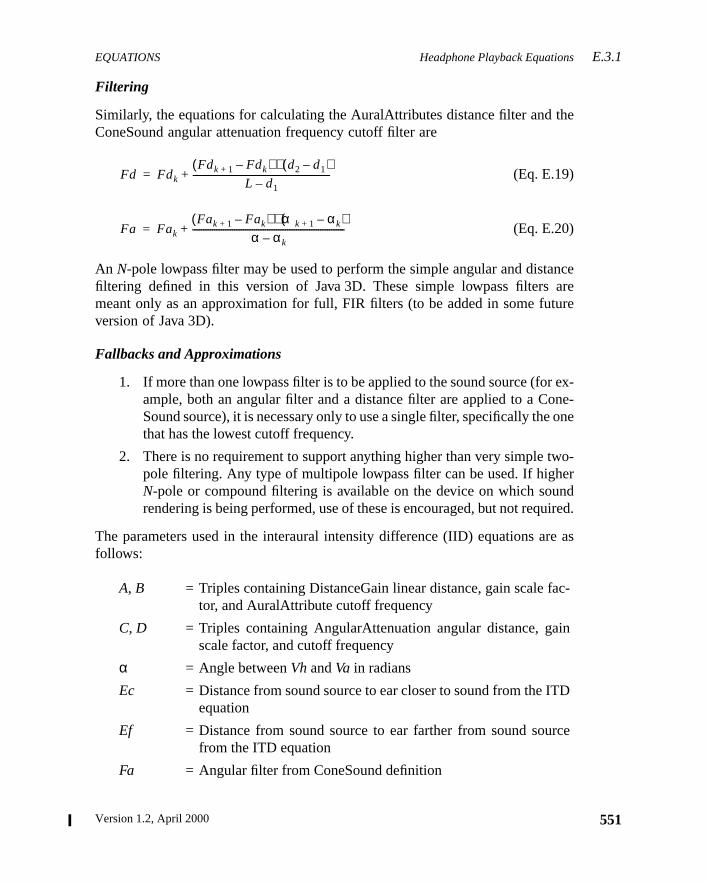
EQUATIONS Headphone Playback EquationsE.3.1
the
nceareure
ex-ne-one
wo-erndired.
e as
c-
in
D
ce
Filtering
Similarly, the equations for calculating the AuralAttributes distance filter andConeSound angular attenuation frequency cutoff filter are
(Eq. E.19)
(Eq. E.20)
An N-pole lowpass filter may be used to perform the simple angular and distafiltering defined in this version of Java 3D. These simple lowpass filtersmeant only as an approximation for full, FIR filters (to be added in some futversion of Java 3D).
Fallbacks and Approximations
1. If more than one lowpass filter is to be applied to the sound source (forample, both an angular filter and a distance filter are applied to a CoSound source), it is necessary only to use a single filter, specifically thethat has the lowest cutoff frequency.
2. There is no requirement to support anything higher than very simple tpole filtering. Any type of multipole lowpass filter can be used. If highN-pole or compound filtering is available on the device on which sourendering is being performed, use of these is encouraged, but not requ
The parameters used in the interaural intensity difference (IID) equations arfollows:
A, B = Triples containing DistanceGain linear distance, gain scale fator, and AuralAttribute cutoff frequency
C, D = Triples containing AngularAttenuation angular distance, gascale factor, and cutoff frequency
α = Angle betweenVh andVa in radians
Ec = Distance from sound source to ear closer to sound from the ITequation
Ef = Distance from sound source to ear farther from sound sourfrom the ITD equation
Fa = Angular filter from ConeSound definition
Fd Fdk
Fdk 1+ Fdk–( ) d2 d1–( )⋅L d1–
--------------------------------------------------------------+=
Fa Fak
Fak 1+ Fak–( ) αk 1+ αk–( )⋅α αk–
---------------------------------------------------------------------+=
551Version 1.2, April 2000
E.3.1 Headphone Playback Equations EQUATIONS
552
deltae haser this
d, the
io is
tio is
he
n,
E.3.1.3 Doppler Effect Equations
Between two snapshots of the head and the sound source positions sometime apart, the distance between the head and source is compared. If therbeen no change in the distance between the head and the sound source ovdelta time, the Doppler effect equation is
(Eq. E.21)
If there has been a change in the distance between the head and the sounDoppler effect equation is
(Eq. E.22)
When the head and sound are moving toward each other (the velocity ratgreater than 1.0), the velocity ratio equation is
(Eq. E.23)
When the head and sound are moving away from each other (the velocity raless than 1.0), the velocity ratio equation is
(Eq. E.24)
Fd = Distance filter from AuralAttributes
Ga = Angular gain attenuation scale factor
Gd = Distance gain attenuation scale factor
Gi = Initial gain scale factor
Gr = Current AuralAttribute region’s gain scale factor
I = Stereo sound image
L = Listener distance from sound source
maxNumS= Maximum number of sound sources for the audio device that tapplication is using for playback
numS = Number of sound sources
sample = Sound digital sample with a specific sample rate, bit precisioand an optional encoding and/or compression format
Vh = Vector from center ear to sound source
f′ f=
f′ f Af v⋅ ⋅=
vS Ar⋅( ) ∆v h t,( ) Av⋅( )+S Ar⋅( ) ∆v s t,( ) Av⋅( )–
-------------------------------------------------------------=
vS Ar⋅( ) ∆v h t,( ) Av⋅( )–S Ar⋅( ) ∆v s t,( ) Av⋅( )+
-------------------------------------------------------------=
The Java 3D API Specification
EQUATIONS Headphone Playback EquationsE.3.1
d is
ce insound
andundf thenottion
The parameters used in the Doppler effect equations are as follows:
Note: If the adjusted velocity of the head or the adjusted velocity of the soungreater than the adjusted speed of sound, is undefined.
E.3.1.4 Reverberation Equations
The overall reverberant sounds, used to give the impression of the aural spawhich the active/enabled source sources are playing, is added to the stereoimage output from equation E.14.
(Eq. E.25)
Reverberation for each sound is approximated in the following:
(Eq. E.26)
Note that the reverberation calculation outputs the same image to both leftright output signals (thus there is a single monaural calculation for each soreverberated). Correct first-order (early) reflections, based on the location osound source, the listener, and the active AuralAttribute’s bounds, arerequired for this version of Java 3D. Approximations based on the reverbera
Af = AuralAttribute frequency scale factor
Ar = AuralAttribute rolloff scale factor
Av = AuralAttribute velocity scale factor
∆v = Delta velocity
f = Frequency of sound
h = Listener’s head position
v = Ratio of delta velocities
Vh = Vector from center ear to sound source
s = Sound source position
S = Speed of sound
t = Time
f′
I ′ t( ) l r,[ ] I t( ) l r,[ ] Rii
numS
∑+=
Ri Gr j Sample t( )i⋅( ) D t Tr j⋅( )+( )•[ ]j
fLoop
∑=
553Version 1.2, April 2000
E.3.2 Speaker Playback Equations EQUATIONS
554
elay
oope
ingrer of
beach
ec-allnd
ystem
n,
e
delay time, either suppled by the application or calculated as the average dtime within the selected AuralAttribute’s application region, will be used.
The feedback loop is repeated until AuralAttribute’s reverberation feedback lcount is reached orGr j ≤ 0.000976 (effective zero amplitude, –60 dB, using thmeasure of –6 dB drop for every doubling of distance).
Fallbacks and Approximations
1. Reducing the number of feedback loops repeated while still maintainthe overall impression of the environment. For example, if –10 dB weused as the drop in gain for every doubling of distance, a scale facto0.015625 could be used as the effective zero amplitude, which canreached in only 15 loop iterations (rather than the 25 needed to re0.000976).
2. Using preprogrammed “room” reverberation algorithms that allow seltion of a fixed set of “reverberation types” (for example, large hall, smliving room), which have implied reflection coefficients, delay times, afeedback loop durations.
The parameters used in the reverberation equations are as follows:
E.3.2 Speaker Playback Equations
Different speaker playback equations are used depending on whether the suses monaural or stereo speakers.
D = Delay function
fLoop = Reverberation feedback loop count
Gr = Reverberation coefficient acting as a gain scale-factor
I = Stereo image of unreflected sound sources
R = Reverberation for each sound sources
Sample= Sound digital sample with a specific sample rate, bit precisioand an optional encoding and/or compression format
t = Time
Tr = Reverberation delay time (approximating first-order delay in thAuralAttribute region)
The Java 3D API Specification
EQUATIONS Speaker Playback EquationsE.3.2
inglee isand
uded
eardand
mustenu-d sig-tions
rs arethe
ed for
n-
ad-
D,
E.3.2.1 Monaural Speaker Output
The equations for headphone playback need only be modified to output a ssignal, rather than two signals for left and right transducers. Although theronly one speaker, distance and filter attenuation, Doppler effect, elevation,front and back cues can be distinguished by the listener and should be inclin the sound image generated.
E.3.2.2 Stereo Speaker Output
In a two-speaker playback system, the signal from one speaker is actually hby both ears, and this affects the spectral balance and interaural intensitytime differences heard by each of the listener’s ears. Crosstalk cancellationbe performed on the right and left signal to compensate for the delayed attated signal heard by the ear opposite the speaker. Thus a delayed attenuatenal for each of the stereo signals must be added to the output from the equafor headphone playback.
The equations for stereo speaker playback assume that the two speakeplaced symmetrically about the listener (at the same off-axis angle fromviewing axis at an equal distance from the center of the listener’s head).
(Eq. E.27)
(Eq. E.28)
The parameters used in the crosstalk equations, expanding on the terms usthe equations for headphone playback, are as follows:
α = Angle between vectors from speaker to near and far ears
D = Delay function of signal variant over time
G = Gain attenuation scale factors function taking initial distance and agular gain scale factors into account
I = Sound image for left and right stereo signals calculated as for hephone output
P = Distance difference between near ear and far ear as defined for ITthe speaker substituted for the sound source in equation
t = Time
I ′ t( )l I t( )l D t( ) G P α,( ) I t( )r⋅[ ]•[ ]+=
I ′ t( )r I t( )r D t( ) G P α,( ) I t( )l⋅[ ]•[ ]+=
555Version 1.2, April 2000
E.4 Texture Mapping Equations EQUATIONS
556
ans-e,kingcom-ode
rim-
ple
ok upxturet
s:
E.4 Texture Mapping Equations
Texture mapping can be divided into two steps. The first step takes the trformed s and t (and possiblyr) texture coordinates, the current texture imagand the texture filter parameters and computes a texture color based on looup the texture coordinates in the texture map. The second step applies theputed texture color to the incoming pixel color using the specified texture mfunction.
E.4.1 Texture Lookup
The texture lookup stage maps a texture image onto a geometric polygonal pitive. The most common method for doing this is to reverse map thes andt coor-dinates from the primitive back onto the texture image, then filter and resamthe image. In the simplest case, a point ins, t space is transformed into au, vaddress in the texture image space (Eq. E.29), then this address is used to lothe nearest texel value in the image. This method, used when the selected tefilter function isBASE_LEVEL_POINT, is called nearest-neighbor sampling or poinsampling.
(Eq. E.29)
(Eq. E.30)
(Eq. E.31)
If the texture boundary mode isREPEAT, then only the fractional bits ofs and tare used, ensuring that boths andt are less than 1.
If the texture boundary mode isCLAMP, then thes andt values are clamped to bein the range [0, 1] before being mapped intou andv values. Further, ifs ≥ 1, theni is set towidth– 1; if t ≥ 1, thenj is set toheight– 1.
The parameters in the point-sampled texture lookup equations are as follow
width = Width, in pixels, of the texture image
height = Height, in pixels, of the texture image
s = Interpolateds coordinate at the pixel being textured
t = Interpolatedt coordinate at the pixel being textured
v t height⋅=
u s width⋅=
i trunc u( )=
j trunc v( )=
Ct Ti j,=
The Java 3D API Specification
EQUATIONS Texture Lookup E.4.1
ither
tex-x-
ingleisapsag-g:
e
fage
lev-xture
The above equations are used when the selected texture filter function—ethe minification or the magnification filter function—isBASE_LEVEL_POINT.Java 3D selects the appropriate texture filter function based on whether theture image is minified or magnified when it is applied to the polygon. If the teture is applied to the polygon such that more than one texel maps onto a spixel, then the texture is said to be minified, and the minification filter functionselected. If the texture is applied to the polygon such that a single texel monto more than one pixel, then the texture is said to be magnified, and the mnification filter function is selected. The selected function is one of the followinBASE_LEVEL_POINT, BASE_LEVEL_LINEAR, MULTI_LEVEL_POINT, or MULTI_
LEVEL_LINEAR. In the case of magnification, the filter will always be one of thtwo base level functions (BASE_LEVEL_POINT or BASE_LEVEL_LINEAR).
If the selected filter function isBASE_LEVEL_LINEAR, then a weighted average othe four texels that are closest to the sample point in the base level texture imis computed.
(Eq. E.32)
(Eq. E.33)
(Eq. E.34)
If the selected filter function isMULTI_LEVEL_POINT or MULTI_LEVEL_LINEAR,the texture image needs to be sampled at multiple levels of detail. If multipleels of detail are needed and the texture object defines only the base level teimage, Java 3D will compute multiple levels of detail as needed.
u = u coordinate in texture image space
v = v coordinate in texture image space
i = Integer row address into texture image
j = Integer column address into texture image
T = Texture image
i0 trunc u 0.5–( )=
j0 trunc v 0.5–( )=
i1 i0 1+=
j1 j0 1+=
α frac u 0.5–( )=
β frac v 0.5–( )=
Ct 1 α–( ) 1 β–( ) Ti0 j0,⋅ ⋅ α 1 β–( ) Ti1 j0,⋅ ⋅+=
1 α–( ) β Ti0 j1, α β Ti1 j1,⋅ ⋅+⋅ ⋅+
557Version 1.2, April 2000
E.4.2 Texture Application EQUATIONS
558
elsg aerly-os-
rfor
per-er
ng,or
ingpo-ded
the
Mipmapping is the most common filtering technique for handling multiple levof detail. If the implementation uses mipmapping, the equations for computintexture color based on texture coordinates are simply those used by the unding rendering API (such as OpenGL or PEX). Other filtering techniques are psible as well.
Fallbacks and Approximations
1. If the texture boundary mode isCLAMP, an implementation may use eithethe closest boundary pixel or the constant boundary color attributethose values ofs or t that are outside the range [0, 1].
2. An implementation can choose a technique other than mipmapping toform the filtering of the texture image when the texture minification filtis MULTI_LEVEL_POINT or MULTI_LEVEL_LINEAR.
3. If mipmapping is chosen by an implementation as the method for filteriit may approximate trilinear filtering with another filtering technique. Fexample, an OpenGL implementation may choose to useLINEAR_MIPMAP_
NEAREST or NEAREST_MIPMAP_LINEAR in place ofLINEAR_MIPMAP_LIN-EAR.
E.4.2 Texture Application
Once a texture color has been computed, this color is applied to the incompixel color. If lighting is enabled, only the emissive, ambient, and diffuse comnents of the incoming pixel color are modified. The specular component is adinto the modified pixel color after texture application.
The equations for applying that color to the original pixel color are based ontexture mode, as follows:
REPLACE Texture Mode
(Eq. E.35)
MODULATE Texture Mode
(Eq. E.36)
C′ Ct=
C′ C Ct⋅=
The Java 3D API Specification
EQUATIONS Texture Application E.4.2
,
r
end-
-
olor
or
n
DECAL Texture Mode
(Eq. E.37)
Note that the texture format must be eitherRGB or RGBA.
BLEND Texture Mode
(Eq. E.38)
Note that if the texture format isINTENSITY, alpha is computed identically to redgreen, and blue:
(Eq. E.39)
The parameters used in the texture mapping equations are as follows:
Note thatCrgb indicates the red, green, and blue channels of colorC and thatCαindicates the alpha channel of colorC. This convention applies to the other colovariables as well.
If there is no alpha channel in the texture, a value of 1 is used forCtα in BLEND
andDECAL modes.
When the texture mode is one ofREPLACE, MODULATE, or BLEND, only certain ofthe red, green, blue, and alpha channels of the pixel color are modified, deping on the texture format, as described following:
• INTENSITY: All four channels of the pixel color are modified. The intensity value is used for each ofCtr, Ctg, Ctb, andCtα in the texture applica-tion equations, and the alpha channel is treated as an ordinary cchannel—the equation forC´rbg is also used forC´α.
• LUMINANCE: Only the red, green, and blue channels of the pixel colare modified. The luminance value is used for each ofCtr, Ctg, andCtb in
C = Color of the pixel being texture mapped (if lighting is enabled, thethis does not include the specular component)
Ct = Texture color
Cb = Blend color
C′rgb Crgb 1 Ctα–( ) Ctrgb Ctα⋅+⋅=
C′α Cα=
C′rgb Crgb 1 Ctrgb–( ) Cbrgb Ctrgb⋅+⋅=
C′α Cα Ctα⋅=
C′α Cα 1 Ctα–( ) Cbα Ctα⋅+⋅=
559Version 1.2, April 2000
E.4.2 Texture Application EQUATIONS
560
r is
d,
di-
or,enta-
theent
the texture application equations. The alpha channel of the pixel colounmodified.
• ALPHA: Only the alpha channel of the pixel color is modified. The regreen, and blue channels are unmodified.
• LUMINANCE_ALPHA: All four channels of the pixel color are modified.The luminance value is used for each ofCtr, Ctg, andCtb in the texture ap-plication equations, and the alpha value is used forCtα.
• RGB: Only the red, green, and blue channels of the pixel color are mofied. The alpha channel of the pixel color is unmodified.
• RGBA: All four channels of the pixel color are modified.
Fallbacks and Approximations
An implementation may apply the texture to all components of the lit colrather than separating out the specular component. Conversely, an implemtion may separate out the emissive and ambient components in addition tospecular component, potentially applying the texture to the diffuse compononly.
The Java 3D API Specification

Version 1.2, April 2000
A P P E N D I X F
r inng asf theAPI
athe
ge,”
r-.13,
s,u-his
ed toSee
The Utility Packages
THIS appendix summarizes the Java 3D utilities packages.
F.1 The Utility Packages
Thecom.sun.j3d.* packages provide aids to assist the application programmesetting up a user environment and getting a Java 3D application up and runniquickly as possible. The utilities packages contain classes that are not part oformal Java 3D API specification. Since these packages are not part of thespecification, they are subject to change and will evolve over time.
The most useful of these packages are
• utils.universe – contains the SimpleUniverse class, which definesminimal user environment that includes all of the necessary objects on“view” side of the scene graph. See Section F.17, “utils.universe Packafor a description of this package.
• utils.geometry – contains geometry utilities, such as stripification, nomal generation, tessellation, and primitive construction. See Section F“utils.geometry Package,” for a description of this package.
• utils.picking – contains the PickIntersection, PickTool, PickCanvaand PickResult classes, which simplify the construction of picking rotines. See Section F.15, “utils.picking Package,” for a description of tpackage.
• loaders – contains the Loader and Scene interfaces, which can be usimplement a variety of Java 3D loaders in a standard manner.Section F.5, “loaders Package,” for a description of this package.
561
F.2 Package Overview THE UTILITY PACKAGES
562
d’s
d-
-
.
l
,
F.2 Package Overview
The Java 3D utilities packages are all in thecom.sun.j3d hierarchy. Table F-1 liststhe utilities packages.
Table F-1 Utilities Packages
Package Name Description
audioengines Useful only to people writing audio device drivers.
audioengines.javasound Defines an audio output device that accesses JavaSounsound mixer functionality.
loaders Used in the construction of file loaders.
loaders.lw3d Implements a loader for Lightwave 3D scene files.
loaders.objectfile Implements a loader for Wavefront object files.
utils.applet Enables creating Java applets that can also run as stanalone applications.
utils.behaviors.interpolators Enhances the Interpolator class with the TCB (KochanekBartels) spline interpolation.
utils.behaviors.keyboard Useful for controlling the scene graph behavior from thekeyboard.
utils.behaviors.mouse Useful for controlling scene graph behavior with themouse, specifically, object rotation, translation, and zoom
utils.compression Useful for geometry compression.
utils.geometry Includes geometry utilities, such as stripification, normageneration, tessellation, and primitive construction.
utils.image Useful for loading Java 3D texture objects.
utils.picking Useful for defining picking operations and retrieving in-formation about the picked object.
utils.picking.behaviors Combines picking with mouse-based rotation, translationand zoom behaviors.
utils.universe Useful for setting up a user environment to get a Java 3Dprogram up and running quickly and easily.
The Java 3D API Specification
THE UTILITY PACKAGES audioengines.javasound Package F.4
olasses
uld let
hte-
.
e”e
.
ple
d’s
F.3 audioengines Package
Thecom.sun.j3d.audioengines package is useful only to people writing audidevice drivers. Java 3D application developers are not expected to use the cin this package.
Table F-2 lists the classes in thecom.sun.j3d.audioengines package.
F.4 audioengines.javasound Package
The com.sun.j3d.audioengines.javasound package contains a single publicclass that implements a JavaSound-based audio device. Most programs shothe SimpleUniverse (or Viewer) class in theuniverse package construct the audiodevice.
Table F-3 lists the class in thecom.sun.j3d.audioengines.javasound package.
Table F-2 audioengines Classes
Class Description
AudioEngine Extends: ObjectImplements: AudioDeviceEncapsulates basic information about the AudioDevice, sucas the playback type (headphones, monaural speakers, or sreo speakers) and the listener’s distance from the speakers
AudioEngine3D Extends: AudioEngineImplements: AudioDevice3DDefines an audio output device that generates sound “imagfrom high-level sound parameters passed to it while the scengraph is active.
AuralParameters Extends: ObjectDefines a set of fields that correspond to AuralAttribute fields
Sample Extends: ObjectDefines the data and methods associated with a sound samplayed through the AudioDevice.
Table F-3 audioengines.javasound Package
Class Description
JavaSoundMixer Extends: AudioEngine3DDefines an audio output device that accesses JavaSounsound mixer functionality.
563Version 1.2, April 2000
F.5 loaders Package THE UTILITY PACKAGES
564
ne,nner.ence.
-
a-
r a-
e
F.5 loaders Package
The com.sun.j3d.loaders package contains two interfaces, Loader and Scethat can be used to implement a variety of Java 3D loaders in a standard maBase classes that implement these interfaces are also included as a conveni
F.5.1 Interfaces
Table F-4 lists the interfaces in thecom.sun.j3d.loaders package.
F.5.2 Classes
Table F-5 lists the classes in thecom.sun.j3d.loaders package.
Table F-4 loaders Package Interfaces
Interface Description
Loader Used to specify the location and elements of a file format toload. The interface is used to give loaders of various file formats a common public interface.
Scene A set of methods used to extract Java 3D scene graph informtion from a file loader utility. The interface is used to giveloaders of various file formats a common public interface.
Table F-5 loaders Package Classes
Class Description
LoaderBase Extends: ObjectImplements: LoaderAbstract base class that can be used as a starting point foLoader. A specific file loader could extend this class and implement the load methods.
SceneBase Extends: ObjectImplements: SceneResponsible for both the storage and retrieval of data from thScene. Most loaders will not need to extend this class.
The Java 3D API Specification
THE UTILITY PACKAGES loaders.objectfile Package F.7
li-
t
r.
e
l
F.5.3 Exceptions
Table F-6 lists the exceptions in thecom.sun.j3d.loaders package.
F.6 loaders.lw3d Package
Thecom.sun.j3d.loaders.lw3d package provides a file loader that allows appcations to load Lightwave 3D scene files.
Table F-7 lists the class in thecom.sun.j3d.loaders.lw3d package.
F.7 loaders.objectfile Package
The com.sun.j3d.loaders.objectfile package provides a file loader thaallows applications to load Wavefront object files.
Table F-8 lists the class in thecom.sun.j3d.loaders.objectfile package.
Table F-6 loaders Package Exceptions
Exception Description
IncorrectFormatException Extends: RuntimeExceptionIndicates that a file of an incorrect type was passed to a loade
ParsingErrorException Extends: RuntimeExceptionIndicates that the loader encountered a problem parsing thspecified file.
Table F-7 loaders.lw3d Package
Class Description
Lw3dLoader Extends: loaders.lw3d.TextfileParserImplements: LoaderAllows users to load Lightwave 3D scene files.
Table F-8 loaders.objectfile Package
Class Description
ObjectFile Extends: ObjectImplements: LoaderImplements the Loader interface for the Wavefront .obj fileformat, a standard 3D object file format created for use withWavefront’s Advanced Visualizer™ and available for pur-chase from Viewpoint DataLabs, as well as other 3D modecompanies.
565Version 1.2, April 2000
F.8 utils.applet Package THE UTILITY PACKAGES
566
e,plica-
Labs
TCBs to
-
)
r-
F.8 utils.applet Package
The com.sun.j3d.utils.applet package includes a single class, MainFramthat enables the creation of Java applets that can also run as standalone aptions. The MainFrame class was developed by Jef Poskanzer of Acme<[email protected]>.
Table F-9 lists the class in thecom.sun.j3d.applet package.
F.9 utils.behaviors.interpolators Package
The com.sun.j3d.utils.behaviors.interpolators package provides spline-based interpolators using KCB (Kochanek-Bartels) splines (also known as theor Tension-Continuity-Bias spline). Applications can use these interpolatorimplement key-frame animation sequences.
Table F-10 lists the classes in thecom.sun.j3d.utils.behaviors.interpola-tors package.
Table F-9 utils.applet Package
Class Description
MainFrame Extends: FrameImplements: java.lang.Runnable, java.applet.AppletStub,java.applet.AppletContextAllows a Java applet to run as an application.
Table F-10 utils.behaviors.interpolators Package
Class Description
KBCubicSplineCurve Extends: ObjectA container class that holds a number of cubic spline segments.
KBCubicSplineSegment Extends: ObjectCreates the representation of a KCB (Kochanek-Bartelsspline.
KBKeyFrame Extends: ObjectRepresents a Key Frame that can be used for Kochanek-Batels spline interpolation.
The Java 3D API Specification
THE UTILITY PACKAGES utils.behaviors.mouse PackageF.11
tle for
eper-
de
he,di-
e
dnts
F.10 utils.behaviors.keyboard Package
The com.sun.j3d.utils.behaviors.keyboard package contains classes thatake keyboard events and turns them into transform changes that are suitabuse in modifying the ViewPlatform’s transformation matrix for navigation.
Table F-11 lists the classes in thecom.sun.j3d.utils.behaviors.keyboardpackage.
F.11 utils.behaviors.mouse Package
The com.sun.j3d.utils.behaviors.mouse package contains classes that usmouse events to modify object or viewing transformations. Subclasses exist toform rotation, translation, and zoom operations.
KBRotPosScaleSplinePathIn-terpolator
Extends: KBSplinePathInterpolatorDefines a behavior that varies the rotational, translational, anscale components of its target TransformGroup by using thKochanek-Bartels cubic spline interpolation to interpolateamong a series of key frames (using the value generated by tspecified Alpha object). The interpolated position, orientationand scale are used to generate a transform in the local coornate system of this interpolator.
KBSplinePathInterpolator Extends: InterpolatorDefines the base class for all KCB (Kochanek-Bartels) SplinPath Interpolators.
Table F-11 utils.behaviors.keyboard Package
Class Description
KeyNavigator Extends: ObjectAccumulates AWT key events (key press and key release) ancomputes a new transform based on the accumulated eveand elapsed time.
KeyNavigatorBehavior Extends: BehaviorA simple behavior that invokes the KeyNavigator to modifythe view platform transform.
Table F-10 utils.behaviors.interpolators Package (Continued)
Class Description
567Version 1.2, April 2000
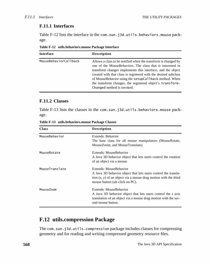
F.11.1 Interfaces THE UTILITY PACKAGES
568
ng
yinctss
e,
n
-
-
F.11.1 Interfaces
Table F-12 lists the interface in thecom.sun.j3d.utils.behaviors.mouse pack-age.
F.11.2 Classes
Table F-13 lists the classes in thecom.sun.j3d.utils.behaviors.mouse pack-age.
F.12 utils.compression Package
Thecom.sun.j3d.utils.compression package includes classes for compressigeometry and for reading and writing compressed geometry resource files.
Table F-12 utils.behaviors.mouse Package Interface
Interface Description
MouseBehaviorCallback Allows a class to be notified when the transform is changed bone of the MouseBehaviors. The class that is interestedtransform changes implements this interface, and the objecreated with that class is registered with the desired subclaof MouseBehavior using thesetupCallback method. Whenthe transform changes, the registered object’stransform-Changed method is invoked.
Table F-13 utils.behaviors.mouse Package Classes
Class Description
MouseBehavior Extends: BehaviorThe base class for all mouse manipulators (MouseRotatMouseZoom, and MouseTranslate).
MouseRotate Extends: MouseBehaviorA Java 3D behavior object that lets users control the rotatioof an object via a mouse.
MouseTranslate Extends: MouseBehaviorA Java 3D behavior object that lets users control the translation (x, y) of an object via a mouse drag motion with the thirdmouse button (alt-click on PC).
MouseZoom Extends: MouseBehaviorA Java 3D behavior object that lets users control thez axistranslation of an object via a mouse drag motion with the second mouse button.
The Java 3D API Specification
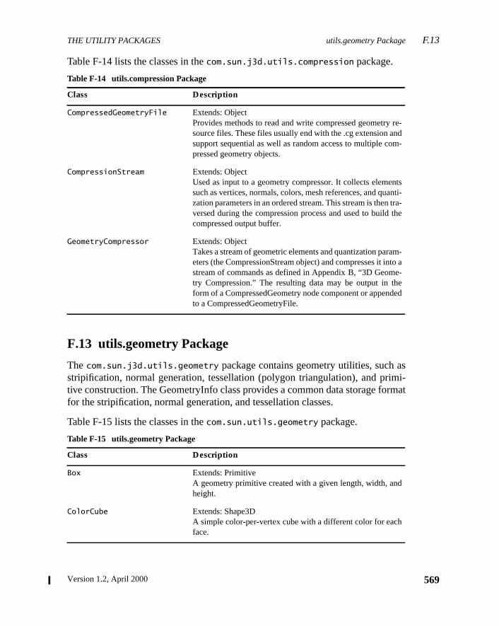
THE UTILITY PACKAGES utils.geometry Package F.13
smi-rmat
e-d-
tsnti-ra-he
m-o a-
ed
Table F-14 lists the classes in thecom.sun.j3d.utils.compression package.
F.13 utils.geometry Package
Thecom.sun.j3d.utils.geometry package contains geometry utilities, such astripification, normal generation, tessellation (polygon triangulation), and pritive construction. The GeometryInfo class provides a common data storage fofor the stripification, normal generation, and tessellation classes.
Table F-15 lists the classes in thecom.sun.utils.geometry package.
Table F-14 utils.compression Package
Class Description
CompressedGeometryFile Extends: ObjectProvides methods to read and write compressed geometry rsource files. These files usually end with the .cg extension ansupport sequential as well as random access to multiple compressed geometry objects.
CompressionStream Extends: ObjectUsed as input to a geometry compressor. It collects elemensuch as vertices, normals, colors, mesh references, and quazation parameters in an ordered stream. This stream is then tversed during the compression process and used to build tcompressed output buffer.
GeometryCompressor Extends: ObjectTakes a stream of geometric elements and quantization paraeters (the CompressionStream object) and compresses it intstream of commands as defined in Appendix B, “3D Geometry Compression.” The resulting data may be output in theform of a CompressedGeometry node component or appendto a CompressedGeometryFile.
Table F-15 utils.geometry Package
Class Description
Box Extends: PrimitiveA geometry primitive created with a given length, width, andheight.
ColorCube Extends: Shape3DA simple color-per-vertex cube with a different color for eachface.
569Version 1.2, April 2000
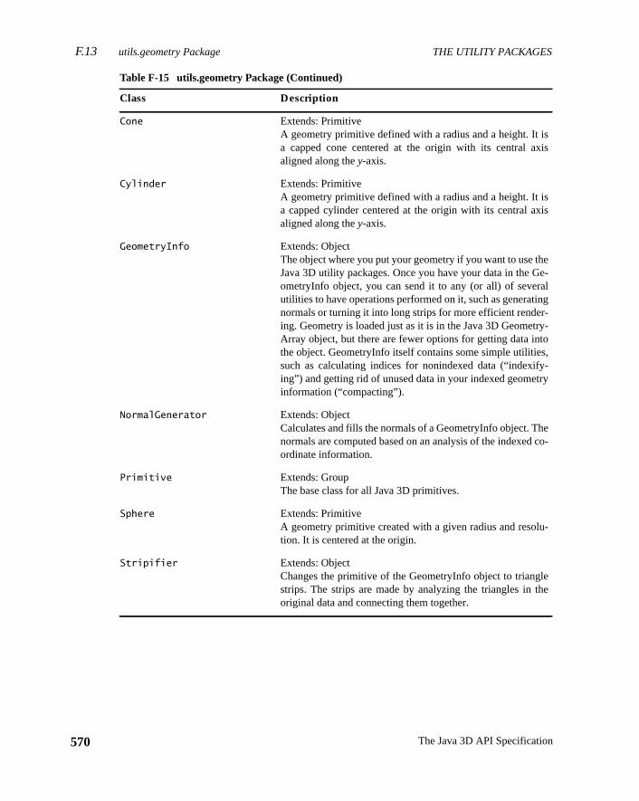
F.13 utils.geometry Package THE UTILITY PACKAGES
570
s
s
e-
lg
-
,-
o-
-
e
Cone Extends: PrimitiveA geometry primitive defined with a radius and a height. It isa capped cone centered at the origin with its central axialigned along they-axis.
Cylinder Extends: PrimitiveA geometry primitive defined with a radius and a height. It isa capped cylinder centered at the origin with its central axialigned along they-axis.
GeometryInfo Extends: ObjectThe object where you put your geometry if you want to use thJava 3D utility packages. Once you have your data in the GeometryInfo object, you can send it to any (or all) of severautilities to have operations performed on it, such as generatinnormals or turning it into long strips for more efficient render-ing. Geometry is loaded just as it is in the Java 3D GeometryArray object, but there are fewer options for getting data intothe object. GeometryInfo itself contains some simple utilitiessuch as calculating indices for nonindexed data (“indexifying”) and getting rid of unused data in your indexed geometryinformation (“compacting”).
NormalGenerator Extends: ObjectCalculates and fills the normals of a GeometryInfo object. Thenormals are computed based on an analysis of the indexed cordinate information.
Primitive Extends: GroupThe base class for all Java 3D primitives.
Sphere Extends: PrimitiveA geometry primitive created with a given radius and resolution. It is centered at the origin.
Stripifier Extends: ObjectChanges the primitive of the GeometryInfo object to trianglestrips. The strips are made by analyzing the triangles in thoriginal data and connecting them together.
Table F-15 utils.geometry Package (Continued)
Class Description
The Java 3D API Specification
THE UTILITY PACKAGES utils.picking Package F.15
er,ale
ickma-
nglso
dan
.s-e
r
F.14 utils.image Package
Thecom.sun.j3d.utils.image package contains a single class, TextureLoadthat is used to load a Java 3D texture object from a file. It will automatically scthe image to a power of two and, optionally, compute mipmaps.
Table F-16 lists the class in thecom.sun.j3d.utils.image package.
F.15 utils.picking Package
Thecom.sun.j3d.utils.picking package includes classes that construct a pshape from a 2D mouse location, initiate a picking operation, and retrieve infortion about the picked object(s).
Table F-17 lists the classes in thecom.sun.j3d.utils.picking package.
Text2D Extends: Shape3DCreates a texture-mapped rectangle that displays the text strisupplied by the user, given the appearance parameters asupplied by the user.
Triangulator Extends: ObjectTurns arbitrary polygons into triangles so they can be rendereby Java 3D. Polygons can be concave or nonplanar,and ccontain holes (see GeometryInfo).
Table F-16 utils.image Package
Class Description
TextureLoader Extends: ObjectUsed for loading a texture from an Image or BufferedImageMethods are provided to retrieve the Texture object and the asociated ImageComponent object or a scaled version of thImageComponent object. The default format is RGBA. Othelegal formats are: RGBA, RGBA4, RGB5_A1, RGB, RGB4,RGB5, R3_G3_B2, LUM8_ALPHA8, LUM4_ALPHA4, LU-MINANCE, and ALPHA.
Table F-15 utils.geometry Package (Continued)
Class Description
571Version 1.2, April 2000
F.16 utils.picking.behaviors Package THE UTILITY PACKAGES
572
cked,
s
adt
e
s
t
.ts-g
F.16 utils.picking.behaviors Package
The com.sun.j3d.utils.picking.behaviors package combines picking withmouse-based rotation, translation, and zoom behaviors. Once an object is pithat object can be manipulated with the mouse.
F.16.1 Interfaces
Table F-18 lists the interface in thecom.sun.j3d.utils.picking.behaviorspackage.
Table F-17 utils.picking Package
Class Description
PickCanvas Extends: PickToolSimplifies picking using mouse events from a canvas. Thiclass allows picking using canvasx,y locations by generatingthe appropriate pick shape.
PickIntersection Extends: ObjectHolds information about an intersection of a PickShape withNode as part of a PickResult. Information about the intersectegeometry, intersected primitive, intersection point, and closesvertex can be inquired.
PickResult Extends: ObjectStores information about a pick hit. Detailed informationabout the pick and each intersection of the PickShape with thpicked Node can be inquired.
PickTool Extends: ObjectThe base class for picking operations. The picking methodwill return a PickResult object for each object picked, whichcan then be queried to obtain more detailed information abouthe specific objects that were picked.
Table F-18 utils.picking.behaviors Package Interfaces
Interface Description
PickingCallback Allows a class to be notified when a picked object is movedThe class that is interested in object movement implementhis interface, and the object created with that class is registered with the desired subclass of PickMouseBehavior usinthesetupCallback method. When the picked object moves,the registered object’stransformChanged method is in-voked.
The Java 3D API Specification
THE UTILITY PACKAGES utils.universe Package F.17
ntlassandnt,ide
ip-
e
ne
e
s-
-
F.16.2 Classes
Table F-19 lists the classes in thecom.sun.j3d.utils.picking.behaviors pack-age.
F.17 utils.universe Package
Thecom.sun.j3d.universe package is useful for setting up a user environmeto quickly and easily get a Java 3D program up and running. Specifically, this ccreates a Locale, a single ViewingPlatform (with its associated ViewPlatform),a Viewer object (with its associated View, PhysicalBody, PhysicalEnvironmeand AudioDevice). For many applications, the SimpleUniverse class will provall of the necessary functionality.
Table F-20 lists the classes in thecom.sun.j3d.utils.universe package.
Table F-19 utils.picking.behaviors Package Classes
Class Description
PickMouseBehavior Extends: BehaviorBase class that allows users to add picking and mouse manulation to the scene graph.
PickRotateBehavior Extends: PickMouseBehaviorA mouse behavior that allows users to pick and drag scengraph objects.
PickTranslateBehavior Extends: PickMouseBehaviorA mouse behavior that allows users to pick and translate scegraph objects.
PickZoomBehavior Extends: PickMouseBehaviorA mouse behavior that allows users to pick and zoom scengraph objects.
Table F-20 utils.universe Package
Class Description
MultiTransformGroup Extends: ObjectA convenience class that effectively creates a series of TranformGroup nodes connected one to another hierarchically.
PlatformGeometry Extends: BranchGroupHolds any geometry that should be associated with the ViewingPlatform object.
573Version 1.2, April 2000
F.17 utils.universe Package THE UTILITY PACKAGES
574
mlh.-
-
-
e
.-
SimpleUniverse Extends: VirtualUniverseSets up a minimal user environment to get a Java 3D prograup and running quickly and easily. This utility class creates althe necessary objects on the “view” side of the scene grapSpecifically, this class creates a locale—a single ViewingPlatform, and a Viewer object (both with their default values).Many basic Java 3D applications will find that SimpleUni-verse provides all necessary functionality needed by their applications.
Viewer Extends: ObjectHolds all the information that describes the physical and virtual “presence” in the Java 3D universe.
ViewerAvatar Extends: BranchGroupHolds geometry that should be associated with the View’sav-atar.
ViewingPlatform Extends: BranchGroupUsed to set up the “view” side of a Java 3D scene graph. ThViewingPlatform object contains a MultiTransformGroupnode to allow for a series of transforms to be linked togetherTo this structure the ViewPlatform is added as well as any geometry to associate with this view platform.
Table F-20 utils.universe Package (Continued)
Class Description
The Java 3D API Specification
Version 1.2, April 2000
A P P E N D I X G
syouem:
c-c-
er,
NIXS
tory
The Example Program
THIS appendix describes the example programs on the CD-ROM.
G.1 Introduction
Before you can compile Java 3D applications or run the example programs,need to have installed or you need to install the following software on your syst
• Java 2 SDK version 1.2 or later (included on the CD-ROM)
• Java 3D API (included on the CD-ROM)
• OpenGL
Thedemo/java3d directory contains 37 subdirectories. All but two of these diretories (geometry andimages) contain at least one example program. Some diretories contain several example programs.
Each example program consists of two files, a.java file and a.class file. Forexample, theConicWorld directory contains the.java and.class files for sixexample programs: BoxExample, ConicWorld, FlipCylinder, SimpleCylindTexturedCone, and TexturedSphere.
G.2 Running the Example Programs
All of the example programs can be run as standalone applications from a Ushell or a DOS window. The syntax shown in this appendix is for UNIX. In DOwindows, you will need to replace “/” with “ \” and specify the correct drive letterwhen referring to<jdkhome> (for example, “c:\jdk1.2.2”).
For example, to run the HelloUniverse program, change your current direc(“cd”) to the <jdkhome>/demo/java3d/HelloUniverse directory, where
575

G.2.1 Running within a Browser THE EXAMPLE PROGRAMS
576
ol-
n thes, run
wseram
in ape org-in.filesfor-lets
run-rnet
er ontall
ay be
Plug-are
<jdkhome> is the directory in which the Java 2 SDK is installed, and type the flowing:
Each of the other example programs can be run in a similar manner.
Some of the example programs require a larger heap size (memory pool) thadefault provided by Java. To increase the maximum heap size to 64 megabytejava with the “–Xmx64m” option. For example,
Several of the example programs can be run as applets, either within a bro(using Java Plug-in) or by running the applet from within the Java utility progrcalledappletviewer.
G.2.1 Running within a Browser
Java 2 applets, including many Java 3D example programs, can be run withbrowser using Java Plug-in. Special HTML tags are required to cause NetscaInternet Explorer to use the correct version of the Java 2 platform via Java PluAll of the Java 3D example programs that can be run as applets include HTMLthat have been converted to use Java Plug-in. Refer to the following URL for inmation on using Java Plug-in 1.2.2 HTML Converter to convert your own appto run in a browser:
http://java.sun.com/products/plugin/
On Windows, the Java Plug-in is automatically installed along with the Java 2time environment. Applets can be run in either Netscape Communicator or InteExplorer.
On Solaris, Java 3D applets can be run in Netscape Communicator 4.51 or latSolaris 2.6 or later. After installing Netscape Communicator, you need to insJava Plug-in version 1.2 or later. Netscape Communicator and Java Plug-in mdownloaded for free from
http://www.sun.com/solaris/netscape/
Additional patches may be required (see the website for details).
In both cases (Windows and Solaris), Java 3D applets are run within the Javain by opening the Java Plug-in version of the associated HTML file. These filesof the form<demo-name>_plugin.html, where<demo-name> is the name of the
% java HelloUniverse
% java -Xmx64m HelloUniverse
The Java 3D API Specification
THE EXAMPLE PROGRAMS Program Descriptions G.3
ram
n as
efaultJava
n on
-
efault, run
f the
ams.utton
particular Java 3D applet. For example, to run the HelloUniverse example progwithin a browser, open theHelloUniverse/HelloUniverse_plugin.html file inyour browser.
The following page contains links to all of the Java 3D demos that can be ruapplets:
<jdkhome>/demo/java3d/index.html
Just click on the link for a given demo to run that demo within your browser.
Some Java 3D applets require a larger heap size (memory pool) than the dprovided by Java Plug-in. To increase the heap size to 64 megabytes, run thePlug-in Control Panel application (from the Start menu in the Programs sectioWindows) and set the “Java Run Time Parameters” to “–Xmx64m”.
G.2.2 Running within Appletviewer
To run Java 3D applets withinappletviewer, open the original, unconverted version of the associated HTML file (not the “_plugin” version). For example,
Some Java 3D applets require a larger heap size (memory pool) than the dprovided by Java. To increase the maximum heap size to 64 megabytesappletviewer with the “–J–Xmx64m” option. For example,
G.3 Program Descriptions
Several example programs are included in thedemo/java3d directory. All of theexample programs are described here. Code fragments are listed for a few oexample programs.
The mouse can be used to manipulate the view in many of the example progrIn these examples, the left mouse button rotates the view, the middle mouse bzooms in and out, and the right mouse button pans the view.
% appletviewer HelloUniverse.html
% appletviewer -J-Xmx64m HelloUniverse.html
577Version 1.2, April 2000
G.3.1 AWT_Interaction THE EXAMPLE PROGRAMS
578
at. Thisentllo-ter-t is
p thatc-. Thean
tion
G.3.1 AWT_Interaction
Directory:demo/java3d/AWT_Interaction
The AWT_Interaction program displays a cube in a window. A “Rotate” buttonthe top of the window rotates the cube in steps each time the button is selectedprogram demonstrates modifying the scene graph directly from the AWT evthread using the ActionListener interface. This example is derived from the HeUniverse example, but instead of being continuously modified by a RotationInpolator behavior, the object’s TransformGroup is set to a new value thacomputed each time the “Rotate” button is pressed.
The relevant source code fragments fromAWT_Interaction.java follow:
public class AWTInteraction extends Appletimplements ActionListener {
TransformGroup objTrans;float angle = 0.0f;Transform3D trans = new Transform3D();
Button rotateB = new Button("Rotate");
This code creates instance variables for the current angle, the TransformGrouwill be modified, and a button that will trigger the modification. The AWTInteration class implements ActionListener so that it can receive button press eventscreateSceneGraph method (not shown here) creates a root BranchGroup,object TransformGroup, and a color cube, much as in HelloUniverse.
public AWTInteraction() {...Panel p = new Panel();p.add(rotateB);add("North", p);
rotateB.addActionListener(this);...
}
The constructor puts the Rotate button in a panel and adds the AWTInteracclass as an action listener for the button.
The Java 3D API Specification
THE EXAMPLE PROGRAMS AppearanceG.3.3
entized
ifiescts ofevereansWT
st pro-the
pear-oosetheaf is
of theierar-pear-
g tet-per-
public void actionPerformed(ActionEvent e) {if (e.getSource() == rotateB) {
angle += Math.toRadians(10);trans.rotY(angle);objTrans.setTransform(trans);
}}
The actionPerformed method increments theangle, computes a new rotationmatrix, and updates the object’s TransformGroup. Since this is in an AWT evlistener method rather than in a behavior, the transform update is not synchronwith the Java 3D renderer. In particular, if such an event listener method modtwo objects in the Java 3D scene graph, there is no guarantee that the effethose two updates will be seen in the same frame. Also remember that it is nsafe for two threads to modify the same Java 3D object simultaneously. This mthat an object that is being updated by a behavior must not be modified by an Aevent listener.
G.3.2 AlternateAppearance
Directory:demo/java3d/AlternateAppearance
The AlternateAppearanceBoundsTest and the AlternateAppearanceScopeTegrams demonstrate the ability of the AlternateAppearance node to overrideappearance of Shape3D nodes. The programs display a 5× 5 matrix of spheres anda control panel. The control panel allows you to select different scopes and apance colors. The AlternateAppearanceBoundsTest program allows you to chone of three different sizes of BoundingSpheres for the region of influence ofAlternateAppearance node, select whether a bounds object or a bounding leused, and enable or disable the appearance override enable flag in eachobjects. The AlternateAppearanceScopeTest program allows you to set the hchical scoping of the AlternateAppearance node and enable or disable the apance override enable flag in each object in a group of objects.
G.3.3 Appearance
Directory:demo/java3d/Appearance
The AppearanceTest program displays an image background and nine rotatinrahedron primitives. The tetrahedra are constructed with different material proties. The relevant source code fragments fromAppearanceTest.java follow:
579Version 1.2, April 2000
G.3.3 Appearance THE EXAMPLE PROGRAMS
580
raph.
tesre, ine,lidndthe
int row, col;Appearance[][] app = new Appearance[3][3];
for (row = 0; row < 3; row++)for (col = 0; col < 3; col++)
app[row][col] = createAppearance(row * 3 + col);
for (int i = 0; i < 3; i++) {double ypos = (double)(i - 1) * 0.6;for (int j = 0; j < 3; j++) {
double xpos = (double)(j - 1) * 0.6;objRoot.addChild(createObject(app[i][j],
0.12,xpos, ypos));}
}
The above code, extracted from thecreateSceneGraph method, creates a 3× 3array of objects, each with its own Appearance, and adds them to the scene g
ThecreateAppearance method takes in an object index from 0 to 8 and generaa unique Appearance for each object (using a switch statement). The objects aorder from left to right and from bottom to top; an unlit solid, an unlit wire framunlit points, a lit solid, a texture-mapped lit solid, a transparent lit solid, a lit sowith no specularity, a lit solid with only a specular highlight (black ambient adiffuse), and a lit solid with a different material color. The code fragments fortexture mapped and transparent cases follow:
private Appearance createAppearance(int idx) {Appearance app = new Appearance();
// Globally used colorsColor3f black = new Color3f(0.0f, 0.0f, 0.0f);Color3f white = new Color3f(1.0f, 1.0f, 1.0f);
switch (idx) {...case 4:
// Set up the texture mapTextureLoader tex = new TextureLoader(texImage, this);app.setTexture(tex.getTexture());
TextureAttributes texAttr = new TextureAttributes();texAttr.setTextureMode(TextureAttributes.MODULATE);app.setTextureAttributes(texAttr);
The Java 3D API Specification
THE EXAMPLE PROGRAMS AppearanceG.3.3
agee lit
trans-bledrented
aletet-
rahe-
app.setMaterial(new Material(white, black, white,black, 1.0f));
break;
For Appearance number 4, the TextureLoader utility is used to load a JPEG imfrom a file and create a Texture object. TextureAttributes are set up so that thcolor is blended with the texture map (MODULATE). Finally, a lighting Materialobject is created with a default color of white.
case 5:// Set up the transparency propertiesTransparencyAttributes ta = new TransparencyAttributes();ta.setTransparencyMode(ta.BLENDED);ta.setTransparency(0.6f);app.setTransparencyAttributes(ta);
// Set up the polygon attributesPolygonAttributes pa = new PolygonAttributes();pa.setCullFace(pa.CULL_NONE);app.setPolygonAttributes(pa);
// Set up the material propertiesColor3f objColor = new Color3f(0.7f, 0.8f, 1.0f);app.setMaterial(new Material(objColor, black, objColor,
black, 1.0f));break;
...
return app;}
For Appearance number 5, TransparencyAttributes are set up to use blendedparency with the object being 60 percent transparent. Back face culling is disain the PolygonAttributes object so that the front and back faces of the transpaobject are visible. Finally, a lighting Material object is created with the specifiobject color.
The createObject method (not shown) takes in an Appearance object, a scvalue, andx andy position values. From these parameters, it creates a rotatingrahedron that is positioned and scaled appropriately. The geometry for the tetdron is created by theTetrahedron.java file.
581Version 1.2, April 2000
G.3.4 AppearanceMixed THE EXAMPLE PROGRAMS
582
ninepro-ode;tet-
eom-the
G.3.4 AppearanceMixed
Directory:demo/java3d/AppearanceMixed
The AppearanceMixed program displays the same image background androtating tetrahedra (with different material properties) as the AppearanceTestgram described earlier. It adds a pair of triangles that are drawn in immediate mthis immediate-mode rendering is mixed in with the retained-mode objects (therahedra).
An application subclasses Canvas3D and overrides the renderField to render getry in mixed-immediate mode. The relevant source code fragments fromMyCanvas3D class inAppearanceMixed.java follow:
static class MyCanvas3D extends Canvas3D {private GraphicsContext3D gc;...
private IndexedTriangleArray tri =new IndexedTriangleArray(4,
IndexedTriangleArray.COORDINATES |IndexedTriangleArray.NORMALS, 6);
private Point3f vert[];private Vector3f normals[];
public void renderField(int fieldDesc) {computeVert();computeNormals();gc.draw(tri);
}
private void computeVert() {<modify vert[] array>...tri.setCoordinates(0, vert);
}
private void computeNormals() {<compute new normals[] based on vert[] values>...tri.setNormals(0, normals);
}
The Java 3D API Specification
THE EXAMPLE PROGRAMS BackgroundG.3.5
chom-tri-
dTri-
itss lightatede lit.
etry.whichion-
hishe
ions
TherenderField method is called by Java 3D during the rendering loop for eaframe. The AppearanceMixed example overrides this Canvas3D method to cpute a new set of vertices and normals for the pair of triangles and to draw theangles to the canvas. ThecomputeVert andcomputeNormals update thevert andnormals array and then call the methods to copy these changes to the IndexeangleArray object.
public MyCanvas3D(GraphicsConfiguration gcfg) {super(gcfg);...
// Set up the graphics contextgc = getGraphicsContext3D();
// Create the appearance for the triangle fanAppearance app = new Appearance();...gc.setAppearance(app);
// Set up the global lightsColor3f lColor1 = new Color3f(0.7f, 0.7f, 0.7f);Vector3f lDir1= new Vector3f(-1.0f, -1.0f, -1.0f);Color3f alColor = new Color3f(0.2f, 0.2f, 0.2f);gc.addLight(new AmbientLight(alColor));gc.addLight(new DirectionalLight(lColor1, lDir1));
}
The constructor for MyCanvas creates a Graphics3D object and initializesappearance and lights. Note that even though the scene graph also containobjects, they are not used for immediate mode rendering—lights must be creand added to the graphics context in order for immediate mode geometry to b
G.3.5 Background
Directory:demo/java3d/Background
The BackgroundGeometry program demonstrates the use of background geomThe inside of a Sphere is texture mapped and used as background geometry,is rendered by Java 3D as if it were infinitely far away. The background is positand scale-invariant—only rotations affect how the geometry is rendered. Tdemo demonstrates this with a group of boxes drawn in the virtual world. Tviewing platform can be adjusted with the mouse buttons. Notice how translatdo not affect the background, but rotations do.
583Version 1.2, April 2000
G.3.6 Billboard THE EXAMPLE PROGRAMS
584
oard-, and
3D.
rent
The
box.
tedbut-
se of
the
lay
G.3.6 Billboard
Directory:demo/java3d/Billboard
The Bboard and BboardPt programs demonstrate the use of Java 3D’s Billbbehavior to rotate a billboard around they axis and around a fixed point, respectively. Use the left mouse button to rotate the scene, the middle button to zoomthe right button to translate.
Note: Billboard’s functionality has largely been superseded by OrientedShape
G.3.7 ConicWorld
Directory:demo/java3d/ConicWorld
This directory contains a README file and six demonstration programs:
• The ConicWorld program shows spheres, cylinders, and cones of differesolutions and colors.
• The SimpleCylinder program demonstrates a simple cylinder object.left mouse button rotates the cylinder, and the middle button zooms.
• The BoxExample program demonstrates a rotating texture-mappedThe left mouse button rotates the box, and the middle button zooms.
• The FlipCylinder program puts up a textured cylinder that can be rotaand zoomed with the mouse. The left mouse button rotates, the middleton zooms, and the right button translates.
• The TexturedCone and TexturedSphere programs demonstrate the utexture mapping with the Cone and Sphere primitives, respectively.
These programs demonstrate the use of the geometry primitives incom.sun.j3d.utils.geometry package.
G.3.8 FourByFour
Directory:demo/java3d/FourByFour
The FourByFour program is a three-dimensional game of tic-tac-toe on a 4× 4 × 4cube. Once loaded, press the “Instructions” button for information on how to pthe game.
The Java 3D API Specification
THE EXAMPLE PROGRAMS GeometryCompressionG.3.11
howsemblym is
etryeation
newolorata”
in thea tex-nce
n to
aved
(.cg)use.
G.3.9 GearTest
Directory:demo/java3d/GearTest
The GearTest program shows a single rotating gear. The GearBox program sa rotating gear assembly with five gears and gear shafts. The entire gear asscan be manipulated with the mouse. The geometry in this example programathematically computed and demonstrates the use of different Java 3D geomtypes. The Gear, SpurGear, and Shaft classes contain most of the geometry crmethods.
G.3.10 GeometryByReference
Directory:demo/java3d/GeometryByReference
The GeometryByReferenceTest program draws a pair of triangles using thegeometry-by-reference API in the GeometryArray object. The geometry or cdata is modified when the corresponding item is selected from the “Update Dcombo box.
The ImageComponentByReferenceTest program draws a small raster objectupper left corner and a larger texture mapped square, using the same image asture, in the middle of the window. This program demonstrates the new by-refereAPI for passing image data to Java 3D. It also demonstrates the newy-up versusy-down attribute for images. Use the combo boxes at the bottom of the screeselect the desired mode for the raster image and the texture image.
The InterleavedTest program draws a pair of triangles using the new interlegeometry-by-reference API in the GeometryArray object.
G.3.11 GeometryCompression
Directory:demo/java3d/GeometryCompression
The cgview program loads an object from a compressed geometry resourcefile and displays it on the screen. The object can be manipulated with the moRun the program with the following command:
java cgview <.cg file> [object-number]
You can use one of the .cg resource files in thedemo/java3d/geometry directory.The following example will display a galleon (ship):
% java cgview ../geometry/galleon.cg
585Version 1.2, April 2000
G.3.12 HelloUniverse THE EXAMPLE PROGRAMS
586
, andgeom-
.cg. If it
com-
aviore3D
electTher. Asver-
ro-
of a
The obj2cg program reads one or more Wavefront .obj files, compresses themappends the corresponding compressed objects to the specified compressedetry resource (.cg) file. Run the program with the following command:
java obj2cg <.obj file> [<.obj file> ...] <.cg file>
If the .cg file does not exist, it is created. If the file does exist and is a validresource file, the new object(s) are appended to the objects in the existing fileis not a valid .cg file, an exception is thrown.
The ObjectFileCompressor class provides the methods, used by obj2cg, topress Wavefront .obj files into Java 3D CompressedGeometry nodes. TheObject-
FileCompressor.html file is the javadoc that describes the methods.
G.3.12 HelloUniverse
Directory:demo/java3d/HelloUniverse
The HelloUniverse program creates a cube and a RotationInterpolator behobject that rotates the cube at a constant rate ofπ/2 radians per second. The codfor this program is described in Section 1.6.3, “HelloUniverse: A Sample JavaProgram.”
G.3.13 LOD
Directory:demo/java3d/LOD
The LOD program demonstrates the use of the DistanceLOD behavior to sautomatically from among four different resolutions of a shaded, lit sphere.middle mouse button moves the object closer and farther away from the viewethe object gets farther away from the viewer, successively lower-resolutionsions of the sphere are displayed.
G.3.14 Lightwave
Directory:demo/java3d/Lightwave directory
The Viewer program is a loader and viewer for Lightwave 3D scene files. This pgram implements only a subset of the features in Lightwave 3D. TheREADME.txt
file contains release notes for the loader. The Viewer program takes the nameLightwave 3D scene (.lws) file as its only argument. For example,
will display a red cone moving behind a stationary green ball.
% java Viewer ballcone.lws
The Java 3D API Specification
THE EXAMPLE PROGRAMS ObjLoadG.3.17
hene.laneov-clip-
phsThes.
fol-
G.3.15 ModelClip
Directory:demo/java3d/ModelClip
The ModelClipTest and ModelClipTest2 programs show model clipping. TModelClipTest program draws an object that is clipped by a model clipping plaThe mouse can be used to manipulate the object. Note that the clipping pmoves with the object. The ModelClipTest2 program has a fixed object with a mable model clipping plane. The mouse can be used to manipulate the modelping plane.
G.3.16 Morphing
Directory:demo/java3d/Morphing
The Morphing program displays at the bottom of the window a hand that moramong the static views of the three hands at the top of the window.Pyramid2Cube program is a simpler example that morphs among three cube
G.3.17 ObjLoad
Directory:demo/java3d/ObjLoad
The ObjLoad program loads Wavefront object files. Run the program with thelowing command:
java ObjLoad [-s] [-n] [-t] [-c degrees] <.obj file>
where the options are
You can use one of the .obj files in thedemo/java3d/geometry directory. The fol-lowing example will display a galleon (ship):
The relevant source code fragment fromObjLoad.java follows:
-s Spin (no user interaction)-n No triangulation-t No stripification-c Set crease angle for normal generation (default is 60 without
smoothing group info, otherwise 180 within smoothing groups)
% java ObjLoad ../geometry/galleon.obj
587Version 1.2, April 2000
G.3.18 OffScreenCanvas3D THE EXAMPLE PROGRAMS
588
s andcep-could
nders
creenect in
that
rint”
public BranchGroup createSceneGraph(String args[]) {...int flags = ObjectFile.RESIZE;...ObjectFile f = new ObjectFile(flags,
(float)(creaseAngle * Math.PI / 180.0));Scene s = null;try {
s = f.load(filename);}catch (FileNotFoundException e) {
System.err.println(e);System.exit(1);
}catch (ParsingErrorException e) {
System.err.println(e);System.exit(1);
}catch (IncorrectFormatException e) {
System.err.println(e);System.exit(1);
}
objTrans.addChild(s.getSceneGroup());
The above code fragment creates an ObjectFile loader with the desired flagcrease angle, loads the specified filename (checking for file and parsing extions), and adds the loaded objects to the scene graph. This code fragmenteasily be modified to accommodate a variety of loaders.
G.3.18 OffScreenCanvas3D
Directory:demo/java3d/OffScreenCanvas3D
The OffScreenTest program creates a scene graph containing a cube and rethat cube to an on-screen Canvas3D. In thepostSwap routine of the on-screenCanvas3D, an off-screen rendering of the same scene is done to the off-sbuffer. The resulting image is then used as the source image for a Raster objthe scene graph.
The PrintFromButton program is similar to the OffScreenTest program, exceptit doesn’t automatically render to the off-screen buffer during thepostSwap call-back of its on-screen Canvas3D. The off-screen rendering is done when the “Pbutton is pressed.
The Java 3D API Specification
THE EXAMPLE PROGRAMS PickTestG.3.21
3D’s
pro-pe3Dcene,text
agesa 3D
ph-
ntrolviewem-
ctiontheicesheasedode
G.3.19 OrientedShape3D
Directory:demo/java3d/OrientedShape3D
The OrientedTest and OrientedPtTest programs demonstrate the use of JavaOrientedShape3D nodes to create geometry that is oriented about they axis andaround a fixed point, respectively. These are essentially the same examplegrams used in the Billboard example, except that they use an OrientedShanode rather than a Billboard behavior. Use the left mouse button to rotate the sthe middle button to zoom, and the right button to translate. Notice how thedoes not jump around as it does when using a Billboard behavior.
G.3.20 PackageInfo
Directory:demo/java3d/PackageInfo
The PackageInfo program lists the package information for the Java 3D packinstalled on the system. This can be used to determine which version of Javyou are running.
The QueryProperties program lists the values of the properties returned by theque-
ryProperties method of the Canvas3D that is created from the preferred GraicsConfiguration returned by SimpleUniverse.
G.3.21 PickTest
Directory:demo/java3d/PickTest
The PickTest program displays several 3D objects and a control panel. The copanel allows the user to change the pick mode, the pick tolerance, and themode. You can pick and rotate objects with the mouse. The PickTest program donstrates the use of the PickMouseBehavior utility classes.
The IntersectTest program demonstrates the ability to get geometric interseinformation from a picked object. Use the mouse to pick a point on one ofobjects in the window. The program illuminates the picked location and the vertof the primitive with tiny spheres. Information about the picked primitive and tpoint of intersection is printed. The IntersectTest program uses a mouse-bbehavior, IntersectInfoBehavior, to control the picking. The relevant source cfragments fromIntersectInfoBehavior.java follow:
589Version 1.2, April 2000
G.3.21 PickTest THE EXAMPLE PROGRAMS
590
t, ini-llow
ia theand
PickCanvas pickCanvas;PickResult[] pickResult;public IntersectInfoBehavior(Canvas3D canvas3D,
BranchGroup branchGroup,float size) {
pickCanvas = new PickCanvas(canvas3D, branchGroup);pickCanvas.setTolerance(5.0f);pickCanvas.setMode(PickCanvas.GEOMETRY_INTERSECT_INFO);...
The IntersectInfoBehavior class constructor creates a new PickCanvas objectializes the PickCanvas with the desired tolerance, and sets the mode to ageometry intersection information to be retrieved.
public void processStimulus(Enumeration criteria) {...<check for mouse event>
if (eventId == MouseEvent.MOUSE_PRESSED) {int x = ((MouseEvent)event[i]).getX();int y = ((MouseEvent)event[i]).getY();pickCanvas.setShapeLocation(x, y);Point3d eyePos = pickCanvas.getStartPosition();pickResult = pickCanvas.pickAllSorted();if (pickResult != null) {
// Get node infoNode curNode = pickResult[0].getObject();Geometry curGeom = ((Shape3D)curNode).getGeometry();GeometryArray curGeomArray = (GeometryArray) curGeom;// Get closest intersection resultsPickIntersection pi =
pickResult[0].getClosestIntersection(eyePos);
<get specific info from PickIntersection>}
}...
The processStimulus method checks for a mouse event and initiates a pick, vPickCanvas object, at the selected location. It then looks for pick resultsextracts the intersection information from the pick result (if any).
The Java 3D API Specification
THE EXAMPLE PROGRAMS PureImmediateG.3.24
nds-ramsndsn thethe
rotat-lities.
n thisg theintome-lled
ontextbject
G.3.22 PickText3D
Directory:demo/java3d/PickText3D
The PickText3DBounds and PickText3DGeometry programs demonstrate boubased and geometry-based picking of Text3D objects, respectively. Both progallow you to pick and rotate the text strings with the mouse. PickText3DBouuses only bounds-based picking, so the string can be picked anywhere withivicinity of its letters. PickText3DGeometry uses geometry-based picking, sostring can exactly be picked only on one of the letters in the string.
G.3.23 PlatformGeometry
Directory:demo/java3d/PlatformGeometry
The SimpleGeometry program displays two geometry objects: a sphere and aing cube. The sphere is created as PlatformGeometry using the universe utiThis means that it is always in a fixed location relative to the viewer.
G.3.24 PureImmediate
Directory:demo/java3d/PureImmediate
The PureImmediate program demonstrates Java 3D’s pure immediate mode. Imode, objects are not placed into a scene graph but instead are drawn usinGraphicsContext3D drawing methods. The Java 3D renderer for the Canvaswhich the immediate mode graphics are rendered must be stopped prior to imdiate mode rendering. In this mode, the rendering is done from a user-controthread.
The relevant source code fragments fromPureImmediate.java follow:
public class PureImmediate extends Applet implements Runnable {private Canvas3D canvas;private GraphicsContext3D gc = null;private Geometry cube = null;private Transform3D cmt = new Transform3D();
// One rotation (2*PI radians) every 6 secondsprivate Alpha rotAlpha = new Alpha(-1, 6000);
The above code creates instance variables for a Canvas3D, the GraphicsCassociated with the canvas, a geometry object for drawing, a Transform3D o
591Version 1.2, April 2000
G.3.24 PureImmediate THE EXAMPLE PROGRAMS
592
ure-draw-
textlears
for rotation, and an alpha object to allow the rotation to be time-based. The PImmediate class implements Runnable so that it can be run by a user-createding thread.
public void render() {if (gc == null) {
// Set up Graphics contextgc = canvas.getGraphicsContext3D();gc.setAppearance(new Appearance());
// Set up geometrycube = new ColorCube(0.4).getGeometry();
}
// Compute angle of rotation based on alpha valuedouble angle = rotAlpha.value() * 2.0*Math.PI;cmt.rotY(angle);
// Render the geometry for this framegc.clear();gc.setModelTransform(cmt);gc.draw(cube);canvas.swap();
}
public void run() {while (true) {
render();Thread.yield();
}}
Therendermethod renders a single frame. After ensuring that the graphics conis set up and the geometry is created, it computes the new rotation matrix, cthe canvas, draws the cube, and swaps the draw and display buffer. Therun methodis the entry point for our drawing thread. It calls therendermethod in a loop, yield-ing control to other threads once per frame.
The Java 3D API Specification
THE EXAMPLE PROGRAMS SoundG.3.26
view-wing
rs thatead
unds,
ation.d-and a
ys aulated
public PureImmediate() {<set layout of applet, get best graphics config>
canvas = new Canvas3D(config);canvas.stopRenderer();add("Center", canvas);
// Create the universe and viewing branchSimpleUniverse u = new SimpleUniverse(canvas);u.getViewingPlatform().setNominalViewingTransform();// Start a new thread that will continuously rendernew Thread(this).start();
}
The constructor creates the 3D canvas, stops the Java 3D renderer, sets up theing branch (necessary even in pure immediate mode), and starts up the drathread.
G.3.25 ReadRaster
Directory:demo/java3d/ReadRaster
The ReadRaster program creates a scene graph containing a cube and rendecube. In thepostSwap routine of the Canvas3D, the contents of the canvas are rback using the Immediate modereadRaster method. The resulting image is thenused as the source image for a Raster object in the scene graph.
G.3.26 Sound
Directory:demo/java3d/Sound
The SimpleSounds program shows a rotating cube and plays three different soincluding a voice saying “Hello Universe.”
The ReverberateSound program demonstrates different amounts of reverberIt plays a voice saying “Hello Universe” in several different environments, incluing a closet, an acoustic lab, a garage, a dungeon (both medium and large),cavern.
The MoveAppBoundingLeaf program displays a large rotating cube and plasingle point sound source. Two Soundscape nodes are created and manipwith a behavior. This results in one or the other being alternately selected.
593Version 1.2, April 2000
G.3.27 SphereMotion THE EXAMPLE PROGRAMS
594
oserandlighthts.
thIn-singd byulate
, an.
t2D
dis-
as
tton
G.3.27 SphereMotion
Directory:demo/java3d/SphereMotion
The SphereMotion program shows a lit sphere that is continuously moving clto and farther from the viewer. The sphere is lit by two light sources, one fixedone rotating around the sphere. Depending on a command line option, the twosources are created as directional lights (the default), point lights, or spot ligRun the program with the following command:
java SphereMotion [-dir | -point | -spot]
G.3.28 SplineAnim
Directory:demo/java3d/SplineAnim
The SplineAnim program demonstrates the use of KBRotPosScaleSplinePaterpolator (see the description in Table F-10) to do spline animation paths uKochanek-Bartels splines. A red cone is animated along a spline path specifiefive knot points, which are shown as cyan spheres. Use the mouse to manipthe scene.
A control panel allows you to toggle between spline and linear interpolationslider to adjust the speed of the animation, and an animation start/stop butto
G.3.29 Text2D
Directory:demo/java3d/Text2D
The Text2DTest program shows three different types of 2D text using the Texutility class.
G.3.30 Text3D
Directory:demo/java3d/Text3D
The Text3DLoad program permits you to enter your own text and see how itplays in 3D. The command for running Text3DLoad is as follows:
java Text3DLoad [-f fontname] [-t tesselation] <text>
Thefontname variable allows you to specify one of the Java Font names, suchHelvetica, Times Roman, and Courier. Thetesselation variable specifies howfinely to tessellate the font glyphs. Once the text displays, the left mouse burotates the text, the middle button zooms, and the right button translates.
The Java 3D API Specification
THE EXAMPLE PROGRAMS TickTockCollisionG.3.33
thetheationre
age
lou
ounu.
escol-
G.3.31 TextureByReference
Directory:demo/java3d/TextureByReference
The TextureByReference program shows a set of animating textures usingimage component by-reference feature. A control panel allows you to flipimage or to set the texture and geometry by-reference flag, the image orientflag (y-up ory-down), and the image type. It also allows you to control the textuanimation speed and to stop and restart the animation.
G.3.32 TextureTest
Directory:demo/java3d/TextureTest
The TextureImage program displays a rotating cube with a user-specified imfile mapped onto the surface. The command for running TextureImage is
java TextureImage <image-filename> [-f ImageComponent format]
TheImageComponent format variable allows you to specify the format of the pixedata. If you do not specify an image file, the rotating cube will appear white. Ycan use one of the image files in thedemo/java3d/images directory. For example:
will display the rotating cube with an image of earth mapped onto it.
The MultiTextureTest program displays a box with two textures applied to it. Ycan enable different combinations of one or two textures with the pop-up meUse the mouse buttons to manipulate the object.
G.3.33 TickTockCollision
Directory:demo/java3d/TickTockCollision
The TickTockCollision program shows an oscillating colored cube that collidwith two rectangular objects. The rectangular objects change color when theylide with the cube.
% java TextureImage ../images/earth.jpg
595Version 1.2, April 2000
G.3.34 TickTockPicking THE EXAMPLE PROGRAMS
596
anleft
w-
G.3.34 TickTockPicking
Directory:demo/java3d/TickTockPicking
The TickTockPicking program displays a set of nine spinning tetrahedra andoscillating colored cube. Picking the cube or one of the tetrahedra with themouse button causes it to change color.
G.3.35 VirtualInputDevice
Directory:demo/java3d/VirtualInputDevice
This directory contains another version of the HelloUniverse program with vieing position controls implemented via the InputDevice interface.
The Java 3D API Specification
s in ason.
graph.
ate
jectmepilested
a 3Diouslyode.
Glossary
avatarThe software representation of a person as the person appears to othershared virtual universe. The avatar may or may not resemble an actual per
branch graphA graph rooted to a BranchGroup node. See also scene graph and shared
CCClipping coordinates.
center earMidpoint between the left and right ear of the listener.
center eyeMidpoint between the left and right eye of viewer. This is the head coordinsystem origin.
compiledA subgraph may be compiled by an application using thecompile method of theroot node—a BranchGroup or a SharedGroup—of the graph. A compiled obis any object that is part of a compiled graph. An application can compile soor all of the subgraphs that make up a complete scene graph. Java 3D comthese graphs into an internal format. Additionally, Java 3D provides restricaccess to methods of compiled objects or graphs. See also live.
compiled-retained modeOne of three modes in which Java 3D objects are rendered. In this mode, Javrenders the scene graph, or a portion of the scene graph, that has been prevcompiled into an internal format. See also retained mode and immediate m
597Version 1.2, April 2000
GLOSSARY
598
odes.
neral,
jectsh tra-
udears.
m
ioral
content branchA branch graph that contains content-related leaf nodes, such as Shape3D nNo viewing-specific nodes are contained in a content branch.
DAGDirected acyclic graph. A scene graph.
ECEye coordinates.
frustumSee view frustum.
group nodeA node within a scene graph that composes, transforms, selects, and, in gemodifies its descendant nodes. See also leaf node and root node.
HMDHead-mounted display.
image plateThe display area; the viewing screen or head-mounted display.
immediate modeOne of three modes in which Java 3D objects are rendered. In this mode obare rendered directly, under user control, rather than as part of a scene grapversal. See also retained mode and compiled-retained mode.
IIDInteraural intensity difference. The difference between the perceived amplit(gain) of the signal from a source as it reaches the listener’s left and right e
ITDInteraural time difference. The difference in time in the arrival of the signal froa sound source as it reaches the listener’s left and right ears.
leaf nodeA node within a scene graph that contains the visual, auditory, and behavcomponents of the scene. See also group node and root node.
The Java 3D API Specification
raphlivea 3Dlive
lect
a 3De also
also
or
graph.
ther
liveA live graph is any graph that is attached to a Locale object, or a shared gthat is referenced by a live graph. A live object is any object that is part of agraph. Live objects are subject to being traversed and rendered by the Javrenderer. Additionally, Java 3D provides restricted access to methods ofobjects or graphs. See also compiled.
LODLevel of detail. A predefined Behavior that operates on a Switch node to sefrom among multiple versions of an object or collection of objects.
polytopeA bounding volume defined by a closed intersection of half-spaces.
retained modeOne of three modes in which Java 3D objects are rendered. In this mode, Javtraverses the scene graph and renders the objects that are in the graph. Secompiled-retained mode and immediate mode.
root nodeA node within a scene graph that establishes the default environment. Seegroup node and leaf node.
scene graphA collection of branch graphs rooted to a Locale. A virtual universe has onemore scene graphs. See also branch graph and shared graph.
shared graphA graph rooted to a SharedGroup node. See also branch graph and scene
strideThe part of an interleaved array that defines the length of a vertex.
three spaceThree-dimensional space.
view branchA branch graph that contains a ViewPlatform leaf node and may contain ocontent-related leaf nodes for geometry associated with a viewer.
599Version 1.2, April 2000

GLOSSARY
600
orldthat).
view frustumA truncated, pyramid-shaped viewing area that defines how much of the wthe viewer sees. Objects not within the view frustum are not visible. Objectsintersect the boundaries of the viewing frustum are clipped (partially drawn
VPCView platform coordinates.
The Java 3D API Specification
Index
Page numbers in bold specify major references.
2D texture coordinates, 147, 194
3D text, 226, 227, 229
3D texture coordinates, 147, 194
Aabsolute method
Tuple2d, 366
Tuple2f, 371
Tuple3d, 380
Tuple3f, 386
Tuple3i, 393
Tuple4d, 398
Tuple4f, 406
Tuple4i, 414
acceleration of alpha, 289
accessing an object, 318
accessing data by reference, 191
ActionListener, 578
activation radius, 98
activation volume, 98
add methodGMatrix, 454
GVector, 420
HiResCoord, 39
Matrix3d, 433
Matrix3f, 427, 430
Matrix4d, 449
Matrix4f, 440, 442
Transform3D, 183
Tuple2d, 365
Tuple2f, 370
Tuple3d, 379
Tuple3f, 384
Tuple3i, 391
Tuple4d, 397
Tuple4f, 405
Tuple4i, 413
addBranchGraph method, 38
addCanvas3D method, 248
addChild method, 43
addGeometry method, 54
addInputDevice method, 528
addLight method, 357
addScope methodAlternateAppearance, 104
Fog, 68
Light, 73
ModelClip, 66
addSound method, 359
addSwitch method, 310
AFFINE flag, 178
ALIGN_CENTER flag, 230
ALIGN_FIRST flag, 230
ALIGN_LAST flag, 230
allElements method, 274
ALLOW_ALIGNMENT_READflag, 229
ALLOW_ALIGNMENT_WRITEflag, 229
ALLOW_ALPHA_TEST_FUNCTION_READ flag, 131
ALLOW_ALPHA_TEST_FUNCTION_WRITE flag, 131
601Version 1.2, April 2000
INDEX
602
ALLOW_ALPHA_TEST_VALUE_READ flag, 131
ALLOW_ALPHA_TEST_VALUE_WRITE flag, 131
ALLOW_ANGULAR_ATTENUATION_READ flag, 89
ALLOW_ANGULAR_ATTENUATION_WRITE flag, 89
ALLOW_ANTIALIASING_READ flagLineAttributes, 125
PointAttributes, 128
ALLOW_ANTIALIASING_WRITE flagLineAttributes, 125
PointAttributes, 128
ALLOW_APPEARANCE_OVERRIDE_READ flag
Morph, 100
Shape3D, 53
ALLOW_APPEARANCE_OVERRIDE_WRITE flag
Morph, 100
Shape3D, 53
ALLOW_APPEARANCE_READ flagAlternateAppearance, 102
Morph, 99
Shape3D, 53
ALLOW_APPEARANCE_WRITE flagAlternateAppearance, 102
Morph, 99
Shape3D, 53
ALLOW_APPLICATION_BOUNDS_READ flag
Background, 59
Clip, 61
Soundscape, 96
ALLOW_APPLICATION_BOUNDS_WRITE flag
Background, 59
Clip, 61
Soundscape, 96
ALLOW_ATTENUATION_READflag, 75
ALLOW_ATTENUATION_WRITEflag, 75
ALLOW_ATTRIBUTE_GAIN_READflag, 154
ALLOW_ATTRIBUTE_GAIN_WRITEflag, 154
ALLOW_ATTRIBUTES_READflag, 96
ALLOW_ATTRIBUTES_WRITEflag, 96
ALLOW_AUTO_COMPUTE_BOUNDS_READ flag, 23
ALLOW_AUTO_COMPUTE_BOUNDS_WRITE flag, 23
ALLOW_AXIS_READ flag, 56
ALLOW_AXIS_WRITE flag, 56
ALLOW_BACK_DISTANCE_READflag, 61
ALLOW_BACK_DISTANCE_WRITEflag, 61
ALLOW_BLEND_COLOR_READflag, 134
ALLOW_BLEND_COLOR_WRITEflag, 134
ALLOW_BLEND_FUNCTION_READflag, 136
ALLOW_BLEND_FUNCTION_WRITEflag, 136
ALLOW_BOUNDARY_COLOR_READflag, 141
ALLOW_BOUNDARY_MODE_READflag, 141
ALLOW_BOUNDING_BOX_READflag, 229
ALLOW_BOUNDS_READ flag, 23
ALLOW_BOUNDS_WRITE flag, 23
ALLOW_CACHE_READ flag, 151
ALLOW_CACHE_WRITE flag, 151
ALLOW_CHANNELS_USED_READflag, 78
ALLOW_CHARACTER_SPACING_READ flag, 229
ALLOW_CHARACTER_SPACING_WRITE flag, 229
The Java 3D API Specification

INDEX
ALLOW_CHILDREN_EXTENDflag, 42
ALLOW_CHILDREN_READ flag, 42
ALLOW_CHILDREN_WRITE flag, 42
ALLOW_COLLIDABLE_READflag, 24
ALLOW_COLLIDABLE_WRITEflag, 24
ALLOW_COLLISION_BOUNDS_READ flag
Group, 42
Morph, 99
Shape3D, 53
ALLOW_COLLISION_BOUNDS_WRITE flag
Group, 42
Morph, 99
Shape3D, 53
ALLOW_COLOR_INDEX_READflag, 211
ALLOW_COLOR_INDEX_WRITEflag, 211
ALLOW_COLOR_READ flagBackground, 59
ColoringAttributes, 124
Fog, 67
GeometryArray, 192
Light, 71
ALLOW_COLOR_TABLE_READflag, 134
ALLOW_COLOR_TABLE_WRITEflag, 134
ALLOW_COLOR_WRITE flagBackground, 59
ColoringAttributes, 124
Fog, 67
GeometryArray, 192
Light, 71
ALLOW_COLORING_ATTRIBUTES_READ flag, 120
ALLOW_COLORING_ATTRIBUTES_WRITE flag, 120
ALLOW_COMPONENT_READflag, 138
ALLOW_COMPONENT_WRITEflag, 138
ALLOW_CONCENTRATION_READflag, 76
ALLOW_CONCENTRATION_WRITEflag, 76
ALLOW_CONT_PLAY_READ flag, 78
ALLOW_CONT_PLAY_WRITEflag, 78
ALLOW_COORDINATE_INDEX_READ flag, 211
ALLOW_COORDINATE_INDEX_WRITE flag, 211
ALLOW_COORDINATE_READflag, 192
ALLOW_COORDINATE_WRITEflag, 192
ALLOW_COUNT_READ flagCompressedGeometry, 220
GeometryArray, 193
ALLOW_COUNT_WRITE flag, 193
ALLOW_CULL_FACE_READflag, 129
ALLOW_CULL_FACE_WRITEflag, 129
ALLOW_DATA_READ flag, 166
ALLOW_DENSITY_READ flag, 69
ALLOW_DENSITY_WRITE flag, 69
ALLOW_DEPTH_COMPONENT_READ flag, 224
ALLOW_DEPTH_COMPONENT_WRITE flag, 224
ALLOW_DEPTH_ENABLE_READflag, 131
ALLOW_DETACH flag, 44
ALLOW_DIRECTION_READ flagConeSound, 89
DirectionalLight, 74
SpotLight, 76
ALLOW_DIRECTION_WRITE flagConeSound, 89
DirectionalLight, 74
603Version 1.2, April 2000
INDEX
604
SpotLight, 76
ALLOW_DISTANCE_FILTER_READflag, 155
ALLOW_DISTANCE_FILTER_WRITEflag, 155
ALLOW_DISTANCE_GAIN_READflag, 85
ALLOW_DISTANCE_GAIN_WRITEflag, 85
ALLOW_DISTANCE_READ flag, 70
ALLOW_DISTANCE_WRITE flag, 70
ALLOW_DURATION_READ flag, 78
ALLOW_ENABLE_READ flagModelClip, 63
Sound, 78
TexCoordGeneration, 146
Texture, 141
ALLOW_ENABLE_WRITE flagModelClip, 63
Sound, 78
TexCoordGeneration, 146
Texture, 141
ALLOW_FILTER_READ flag, 141
ALLOW_FONT3D_READ flag, 229
ALLOW_FONT3D_WRITE flag, 229
ALLOW_FORMAT_READ flagGeometryArray, 193
ImageComponent, 160
TexCoordGeneration, 146
Texture, 141
ALLOW_FREQUENCY_SCALE_FACTOR_READ flag, 155
ALLOW_FREQUENCY_SCALE_FACTOR_WRITE flag, 155
ALLOW_GEOMETRY_ARRAY_READflag, 99
ALLOW_GEOMETRY_ARRAY_WRITE flag, 99
ALLOW_GEOMETRY_READ flagBackground, 59
CompressedGeometry, 220
Shape3D, 53
ALLOW_GEOMETRY_WRITE flag
Background, 59
Shape3D, 53
ALLOW_HEADER_READ flag, 220
ALLOW_IGNORE_VERTEX_COLORS_READ flag, 131
ALLOW_IGNORE_VERTEX_COLORS_WRITE flag, 131
ALLOW_IMAGE_READ flagBackground, 59
ImageComponent, 160
Raster, 224
Texture, 141
ALLOW_IMAGE_WRITE flagBackground, 59
Raster, 224
Texture, 141
ALLOW_INFLUENCING_BOUNDS_READ flag
AlternateAppearance, 102
Fog, 67
Light, 71
ModelClip, 63
ALLOW_INFLUENCING_BOUNDS_WRITE flag
AlternateAppearance, 102
Fog, 67
Light, 71
ModelClip, 63
ALLOW_INITIAL_GAIN_READflag, 78
ALLOW_INITIAL_GAIN_WRITEflag, 78
ALLOW_INTERSECT flag, 191
ALLOW_IS_PLAYING_READ flag, 78
ALLOW_IS_READY_READ flag, 78
ALLOW_LINE_ATTRIBUTES_READflag, 121
ALLOW_LINE_ATTRIBUTES_WRITEflag, 121
ALLOW_LOCAL_TO_VWORLD_READ flag, 24
ALLOW_LOOP_READ flag, 78
ALLOW_LOOP_WRITE flag, 78
The Java 3D API Specification

INDEX
ALLOW_MATERIAL_READ flag, 120
ALLOW_MATERIAL_WRITEflag, 120
ALLOW_MIPMAP_MODE_READflag, 141
ALLOW_MODE_READ flagOrientedShape3D, 56
PolygonAttributes, 129
TexCoordGeneration, 146
TextureAttributes, 134
TransparencyAttributes, 136
ALLOW_MODE_WRITE flagOrientedShape3D, 56
PolygonAttributes, 129
TextureAttributes, 134
TransparencyAttributes, 136
ALLOW_NORMAL_FLIP_READflag, 129
ALLOW_NORMAL_FLIP_WRITEflag, 129
ALLOW_NORMAL_INDEX_READflag, 211
ALLOW_NORMAL_INDEX_WRITEflag, 211
ALLOW_NORMAL_READ flag, 192
ALLOW_NORMAL_WRITE flag, 192
ALLOW_OFFSET_READ flagPolygonAttributes, 129
Raster, 224
ALLOW_OFFSET_WRITE flagPolygonAttributes, 129
Raster, 224
ALLOW_PATH_READ flag, 229
ALLOW_PATH_WRITE flag, 229
ALLOW_PATTERN_READ flag, 125
ALLOW_PATTERN_WRITE flag, 125
ALLOW_PICKABLE_READ flag, 24
ALLOW_PICKABLE_WRITE flag, 24
ALLOW_PLANE_READ flagModelClip, 63
TexCoordGeneration, 146
ALLOW_PLANE_WRITE flag, 63
ALLOW_POINT_ATTRIBUTES_READflag, 121
ALLOW_POINT_ATTRIBUTES_WRITE flag, 121
ALLOW_POINT_READ flag, 56
ALLOW_POINT_WRITE flag, 56
ALLOW_POLICY_READ flag, 98
ALLOW_POLICY_WRITE flag, 98
ALLOW_POLYGON_ATTRIBUTES_READ flag, 121
ALLOW_POLYGON_ATTRIBUTES_WRITE flag, 121
ALLOW_POSITION_READ flagPointLight, 75
PointSound, 85
Raster, 224
Text3D, 229
ALLOW_POSITION_WRITE flagPointLight, 75
PointSound, 85
Raster, 224
Text3D, 229
ALLOW_PRIORITY_READ flag, 78
ALLOW_PRIORITY_WRITE flag, 78
ALLOW_RASTER_OP_READflag, 131
ALLOW_RASTER_OP_WRITEflag, 131
ALLOW_REF_DATA_READ flagCompressedGeometry, 220
GeometryArray, 193
ALLOW_REF_DATA_WRITE flag, 193
ALLOW_REFLECTION_COEFFICIENT_READ flag, 155
ALLOW_REFLECTION_COEFFICIENT_WRITE flag, 155
ALLOW_REGION_READ flag, 58
ALLOW_REGION_WRITE flag, 58
ALLOW_RELEASE_READ flag, 78
ALLOW_RELEASE_WRITE flag, 78
ALLOW_RENDERING_ATTRIBUTES_READ flag, 121
605Version 1.2, April 2000

INDEX
606
ALLOW_RENDERING_ATTRIBUTES_WRITE flag, 121
ALLOW_REVERB_DELAY_READflag, 155
ALLOW_REVERB_DELAY_WRITEflag, 155
ALLOW_REVERB_ORDER_READflag, 155
ALLOW_REVERB_ORDER_WRITEflag, 155
ALLOW_ROLLOFF_READ flag, 154
ALLOW_ROLLOFF_WRITE flag, 155
ALLOW_SCHEDULING_BOUNDS_READ flag, 78
ALLOW_SCHEDULING_BOUNDS_WRITE flag, 78
ALLOW_SCOPE_READ flagAlternateAppearance, 102
Fog, 67
Light, 71
ModelClip, 63
ALLOW_SCOPE_WRITE flagAlternateAppearance, 102
Fog, 67
Light, 71
ModelClip, 63
ALLOW_SHADE_MODEL_READflag, 124
ALLOW_SHADE_MODEL_WRITEflag, 124
ALLOW_SHARED_GROUP_READflag, 107
ALLOW_SHARED_GROUP_WRITEflag, 107
ALLOW_SIZE_READ flagDepthComponent, 166
ImageComponent, 160
PointAttributes, 127
Raster, 224
Texture, 141
ALLOW_SIZE_WRITE flagPointAttributes, 127
Raster, 224
ALLOW_SOUND_DATA_READflag, 78
ALLOW_SOUND_DATA_WRITEflag, 78
ALLOW_SPREAD_ANGLE_READflag, 76
ALLOW_SPREAD_ANGLE_WRITEflag, 76
ALLOW_STATE_READ flagLight, 71
MultiTextureState, 149
ALLOW_STATE_WRITE flagLight, 71
MultiTextureState, 149
ALLOW_STRING_READ flag, 229
ALLOW_STRING_WRITE flag, 229
ALLOW_SWITCH_READ flag, 48
ALLOW_SWITCH_WRITE flag, 48
ALLOW_TEXCOORD_INDEX_READflag, 211
ALLOW_TEXCOORD_INDEX_WRITEflag, 211
ALLOW_TEXCOORD_READ flag, 192
ALLOW_TEXCOORD_WRITEflag, 192
ALLOW_TEXGEN_READ flag, 120
ALLOW_TEXGEN_WRITE flag, 120
ALLOW_TEXTURE_ATTRIBUTES_READ flag, 120
ALLOW_TEXTURE_ATTRIBUTES_WRITE flag, 120
ALLOW_TEXTURE_READ flag, 120
ALLOW_TEXTURE_UNIT_STATE_READ flag, 121
ALLOW_TEXTURE_UNIT_STATE_WRITE flag, 121
ALLOW_TEXTURE_WRITE flag, 120
ALLOW_TRANSFORM_READ flagTextureAttributes, 134
TransformGroup, 46
ALLOW_TRANSFORM_WRITE flagTextureAttributes, 134
TransformGroup, 46
The Java 3D API Specification
INDEX
ALLOW_TRANSPARENCY_ATTRIBUTES_READ flag, 120
ALLOW_TRANSPARENCY_ATTRIBUTES_WRITE flag, 120
ALLOW_TYPE_READ flag, 224
ALLOW_URL_READ flag, 151
ALLOW_URL_WRITE flag, 151
ALLOW_VALUE_READ flag, 136
ALLOW_VALUE_WRITE flag, 136
ALLOW_VELOCITY_SCALE_FACTOR_READ flag, 155
ALLOW_VELOCITY_SCALE_FACTOR_WRITE flag, 155
ALLOW_VISIBLE_READ flag, 131
ALLOW_VISIBLE_WRITE flag, 131
ALLOW_WEIGHTS_READ flag, 99
ALLOW_WEIGHTS_WRITE flag, 99
ALLOW_WIDTH_READ flag, 125
ALLOW_WIDTH_WRITE flag, 125
alphaacceleration of, 289
test, 132
ALPHA flag, 142
Alpha object, 119, 289
ALPHA_IN_BUFFER flag, 222
alphaAtOneDuration parameter, 291
alphaAtZeroDuration parameter, 291
AlternateAppearance leaf node, 102
AlternateAppearanceBoundsTestprogram, 579
AlternateAppearanceScopeTestprogram, 579
ALWAYS flag, 132
ambient lightcolor, 139
source, 73
AmbientLight leaf node, 73
amplitude scale factor, 77, 156
angle flagAxisAngle4d, 416
AxisAngle4f, 418
angle method
Gvector, 423
Vector2d, 369
Vector2f, 374
Vector3D, 383
Vector3f, 389
Vector4d, 402
Vector4f, 410
angular attenuation, 88, 95
animating rigid objects, 267
animation, 267–314
antialiasing, 126, 128, 255
support for, 261
appearance component, overriding, 102
Appearance object, 8, 119, 356
AppearanceMixed program, 579, 582
applet package, 566
applet run as an application, 566
applets, support for building, 5
appletviewer, 576, 577
application region, 61, 62, 97
application scene graph, 6
ArrayIndexOutOfBoundsException, 537
atmospheric conditions, 156
atmospheric rolloff, 152
attachViewPlatform method, 248
attenuation, pointlight, 76
audio device driver, 335
data, 338
initialization, 336
audio devices, 335–344
audio output device, 563
AudioDevice object, 335–344
AudioDevice3D interface, 338
audioengines package, 563
audioengines.javasound package, 563
aural attributes, 97, 359
AuralAttributes node componentobject, 152, 155, 359
avatar, 243, 574
AWTInteraction class, 578
AWTInteraction program, 578
AxisAngle4d class, 234, 415
607Version 1.2, April 2000
INDEX
608
AxisAngle4f class, 234, 417
Bback clip policy, 251, 252
background color, 356
background geometry, 60, 583
Background leaf node, 59, 356
BACKGROUND_SOUND flag, 339
BackgroundGeometry program, 583
BackgroundSound leaf node, 84
BadTransformException, 537
BASE_LEVEL flag, 142
BASE_LEVEL_LINEAR flag, 143, 557
BASE_LEVEL_POINT flag, 143, 557
Bboard program, 584
BboartPt program, 584
Behavior leaf node, 99, 267, 272
behaviors, 267–314
behaviors.interpolators package, 566
behaviors.keyboard package, 567
behaviors.mouse package, 568
Billboard behavior node, 312
Billboard programs, 584
BLEND flag, 135
blend functiondestination, 138
source, 138
BLEND_ONE flag, 138
BLEND_ONE_MINUS_SRC_ALPHAflag, 138
BLEND_SRC_ALPHA flag, 138
BLEND_ZERO flag, 138
BLENDED flag, 137
blocking driver, 316
BLOCKING flag, 316
boundary mode, 142, 146
bounding region, 59
BoundingBox node componentobject, 170
BoundingLeaf node, 58
BoundingPolytope node componentobject, 174
BoundingSphere node componentobject, 172
Bounds node component object, 168
Box class, 569
BoxExample program, 584
BranchGroup node, 8, 44, 327
browser support, 5
bufferDataPresent constant, 222
BUFFERED_AUDIO_DATA flag, 339
bufferType constant, 222
bundle colors with vertices state bit, 465
bundle normals with vertices statebit, 465
BY_REFERENCE flag, 193, 194
Ccalibration parameters, 521, 522
camera-based view model, 530, 532
helping methods, 532
canvas sizing and movement, 249
Canvas3D object, 28, 238, 239, 257, 522
CapabilityNotSetException, 538
CC (Clipping Coordinates), 535
center eye, 525
cgview program, 585
character string, 230
CHILD_ALL flag , 49
CHILD_MASK flag, 49
CHILD_NONE flag, 49
CLAMP flagTexture, 142
Texture3D, 146
clamp methodTuple2d, 366
Tuple2f, 371
Tuple3d, 380
Tuple3f, 386
Tuple3i, 392
The Java 3D API Specification
INDEX
Tuple4d, 398, 399
Tuple4f, 406
Tuple4i, 414
clampMax methodTuple2d, 366
Tuple2f, 371
Tuple3d, 380
Tuple3f, 386
Tuple3i, 392
Tuple4d, 399
Tuple4f, 406
Tuple4i, 414
clampMin methodTuple2d, 366
Tuple2f, 371
Tuple3d, 380
Tuple3f, 386
Tuple3i, 392
Tuple4d, 398, 399
Tuple4f, 406
Tuple4i, 414
clear method, 360
clearCapability method, 22
clearRect method, 361
clearSound method, 340
Clip leaf node, 61
clip policies, 251
Clipping Coordinates (CC), 535
clipping plane, 61, 62, 63, 251
clone methodBoundingBox, 171
BoundingPolytope, 176
BoundingSphere, 173
Bounds, 168
cloneNode method, 114
cloneNodeComponent method, 114
cloneTree method, 108, 109
cloning subgraphs, 108–117
close methodAudioDevice, 336
InputDevice, 317
closestIntersection methodBoundingBox, 171
BoundingPolytope, 177
BoundingSphere, 173
Bounds, 169
code structure, 268
coexistence coordinates, 512
collision detection, 20
coloralpha present state bit, 466
component information, 124
diffuse, 139, 140
emissive, 139
light, 139
material, 140
parameter, 198
specular, 139
specular highlight, 140
subcommand, 483
COLOR_3 flag, 194
COLOR_4 flag, 194
COLOR_IN_BUFFER flag, 222
Color3b class, 377
Color3f class, 389
Color4b class, 395
Color4f class, 408
ColorCube class, 569
ColoringAttributes object, 123
ColorInterpolator object, 298
colors parameter, 198
combine methodBoundingBox, 171
BoundingPolytope, 176
BoundingSphere, 173
Bounds, 169
compatibility mode, 531
compile methodBranchGroup, 45
SharedGroup, 107
compiled-retained mode, 3, 346
component objects,See node componentobjects
609Version 1.2, April 2000
INDEX
610
CompressedGeometry node componentobject, 219, 222
CompressedGeometryFile class, 569
CompressedGeometryHeader nodecomponent object, 222
compressiongeometry, 459–507, 568
image, 466
compression package, 569
CompressionStream class, 569
computePathInterpolation method, 303
concentration, spotlight, 77
Cone class, 570
cone pick shape, 331
CONE_SOUND flag, 339
ConeSound leaf node, 88
CONGRUENT flag, 177
ConicWorld program, 584
conjugate methodQuat4d, 402
Quat4f, 411
constant polygon offset, 130
coordinate systems, 33, 511–514
head, 512, 515, 525
head tracker, 513
high-resolution, 38
image plate, 513
left image plate, 513
physical, 512
right image plate, 513
tracker base, 513
ViewPlatform, 511
virtual world, 511, 515
COORDINATES flag, 194
copySubMatrix method, 455
create method, 361
cross methodVector3d, 383
Vector3f, 388
cross-product normalization, 188, 429,
435
CULL_BACK flag, 130
CULL_FRONT flag, 130
CULL_NONE flag, 130
currentChild method, 50
currentInterpolationValue flag, 302
currentKnotIndex flag, 302
CYCLOPEAN_EYE_VIEW flag, 518
Cylinder class, 570
cylindrical ray pick shape, 332
cylindrical segment pick shape, 333
Ddangling references, 113
DanglingReferenceException, 538
dashed line, 125
dashed-dotted line, 125
DECAL flag, 134
decal geometry, 47
DecalGroup node, 47
decompress method, 221
decompression, geometry, 460
DECREASING_ENABLE flag, 291
decreasingAlphaDuration parameter, 291
decreasingAlphaRampDurationparameter, 291
DEFAULT_SENSOR_READ_COUNT, 319
defaultWakeupCriterion flag, 294
DEMAND_DRIVEN flag, 316
depth bufferenable flag, 132
freezing, 255
mode, 132
write enable flag, 132
DepthComponent object, 166
DepthComponentFloat object, 167
DepthComponentInt object, 167
DepthComponentNative object, 168
destination blend function, 138
detach method, 45
determinant method
The Java 3D API Specification
INDEX
Matrix3d, 434
Matrix3f, 428
Matrix4d, 452
Matrix4f, 443
Transform3D, 187
difference method, 40
diffuse color, 139, 140
direction, spotlight, 77
directional light, 73
DirectionalLight leaf node, 73
discrete cosine transform, 467
distance attenuation, 88
distance frequency filtering, 152
distance methodHiResCoord, 40
Point2d, 368
Point2f, 373
Point3d, 382
Point3f, 387
Point4d, 400
Point4f, 408
distanceL1 methodPoint2d, 368
Point2f, 373
Point3d, 382
Point3f, 387
Point4d, 400
Point4f, 408
distanceLinf methodPoint2d, 368
Point2f, 373
Point3d, 382
Point3f, 387
Point4d, 400
Point4f, 408
DistanceLOD behavior node, 311
distanceSquared methodPoint2d, 368
Point2f, 373
Point3d, 382
Point3f, 387
Point4d, 400
Point4f, 408
Dopplereffect equations, 552
scale factor, 158
dot methodGVector, 422
Vector2d, 369
Vector2f, 374
Vector3d, 383
Vector3f, 388
Vector4d, 401
Vector4f, 410
dotted line, 125
double bufferingenable flag, 261
override, 358
support for, 261
draw method, 360
duplicateNode method, 114
duplicateNodeComponent method, 114
DURATION_UNKNOWN flag, 78
EEC (Eye Coordinates), 535
emissive color, 139
ENABLE_COLLISION_REPORTINGflag, 24
ENABLE_PICK_REPORTING flag, 24
environment, sound, 95
epsilonEquals methodAxisAngle4d, 417
AxisAngle4f, 419
GMatrix, 457
GVector, 422
Matrix3d, 435
Matrix3f, 429
Matrix4d, 453
Matrix4f, 444
Transform3D, 188
611Version 1.2, April 2000
INDEX
612
Tuple2d, 367
Tuple2f, 372
Tuple3d, 380
Tuple3f, 385
Tuple4d, 398
Tuple4f, 406
EQUAL flag, 132
equals methodAxisAngle4d, 417
AxisAngle4f, 419
BoundingBox, 171
BoundingPolytope, 177
BoundingSphere, 174
Bounds, 169
GMatrix, 457
GVector, 422
HiResCoord, 40
Matrix3d, 435
Matrix3f, 429
Matrix4d, 453
Matrix4f, 444
SceneGraphPath, 327
Transform3D, 188
Tuple2d, 367
Tuple2f, 372
Tuple3b, 376
Tuple3d, 380
Tuple3f, 385
Tuple3i, 392
Tuple4b, 395
Tuple4d, 398
Tuple4f, 406
Tuple4i, 415
equations, 543–560
Doppler effect, 552
exponential fog, 543
fog, 543
headphone playback, 546
lighting, 544
reverberation, 553
sound, 546
speaker playback, 554
texture application, 558
texture lookup, 556
texture mapping, 556
error handling, 537
Euler angles, 181
example programs, 575–??
running, 575
exceptions, 537–542
execution and rendering model, 345–347
execution culling, 271
exponential fog equation, 543
ExponentialFog leaf node, 68
extensibility, 3
extrusion path, 226, 227
Eye Coordinates (EC), 535
eye position manipulation, 522
EYE_LINEAR flag, 147
eyepoint policy, 516
Fface culling flag, 129
FASTEST flagColoringAttributes, 124
Texture, 143
TextureAttributes, 136
TransparencyAttributes, 137
field of view, 252
FIELD_ALL flag, 352
FIELD_LEFT flag, 352
FIELD_RIGHT flag, 352
field-sequential stereo, 260
file loader, 564
finished method, 294
FlipCylinder program, 584
flush methodGraphicsContext3D, 360
J3DGraphics2D, 361
fog equations, 543
Fog leaf node, 66, 356
The Java 3D API Specification
INDEX
Font3D object, 226
FontExtrusion object, 227
forceDuplicate parameter, 109
FORMAT_CHANNEL8 flag, 161
FORMAT_LUM4_ALPHA4 flag, 161
FORMAT_LUM8_ALPHA8 flag, 161
FORMAT_R3_G3_B2 flag, 161
FORMAT_RGB flag, 160
FORMAT_RGB4 flag, 161
FORMAT_RGB5 flag, 161
FORMAT_RGB5_A1 flag, 161
FORMAT_RGB8 flag, 160
FORMAT_RGBA flag, 160
FORMAT_RGBA4 flag, 161
FORMAT_RGBA8 flag, 161
FourByFour program, 584
front clip policy, 251, 252
frustum, 531
frustum culling, 496
frustum method, 189, 533
Ggain scale factor, 87, 93, 152
game support, 6
GearBox program, 585
GearTest program, 585
generalized triangle mesh, 463
generalized triangle strip, 461
genMode parameter, 148
geometrycomponent information, 190
compression, 346, 459–507
data, updating, 206
decompression, 460
grouping, 346
instructions, 474
typesGeometryArray, 191Raster, 223
Geometry object, 8, 190, 360
geometry package, 569
GeometryArray object, 191
GeometryByReferenceTest program, 585
GeometryCompressor class, 569
GeometryInfo class, 570
GeometryStripArray object, 208
GeometryUpdater interface, 206
get methodAxisAngle4d, 416
AxisAngle4f, 418
Color3b, 377
Color3f, 390
Color4b, 395
Color4f, 409
GMatrix, 456
Matrix4d, 446
Matrix4f, 439
PickBounds, 328
PickPoint, 329
PickRay, 329
PickSegment, 330
SensorRead, 323
Transform3D, 186
Tuple2d, 365
Tuple2f, 370
Tuple3b, 376
Tuple3d, 378
Tuple3f, 384
Tuple3i, 391
Tuple4b, 394
Tuple4d, 397
Tuple4f, 405
Tuple4i, 413
getActivationRadius method, 98
getAlignment method, 230
getAlignmentAxis methodBillboard, 314
OrientedShape3D, 57
getAlignmentMode methodBillboard, 314
OrientedShape3D, 57
613Version 1.2, April 2000
INDEX
614
getAllBranchGraphs method, 38
getAllCanvas3Ds method, 249
getAllChildren method, 43
getAllGeometries method, 55
getAllInputDevices method, 528
getAllLights method, 357
getAllLocales method, 36
getAllScopes methodAlternateAppearance, 104
Fog, 68
Light, 73
ModelClip, 66
getAllSounds method, 359
getAllSwitches method, 311
getAlpha method, 295
getAlphaAtOneDuration method, 293
getAlphaAtZeroDuration method, 294
getAlphaTestFunction method, 132
getAlphaTestValue flag, 132
getAlternateCollisionTarget method, 43
getAmbientColor method, 139
getAngleOffsetToSpeaker method, 337
getAngularAttenuation method, 94
getAngularAttenuationLengthmethod, 94
getAppearance methodAlternateAppearance, 103
GraphicsContext3D, 356
Morph, 101
Shape3D, 55
getAppearanceOverrideEnable methodMorph, 101
Shape3D, 55
getApplicationBoundingLeaf methodBackground, 61
Clip, 62
Soundscape, 97
getApplicationBounds methodBackground, 61
Clip, 62
Soundscape, 97
getArmingBounds method
WakeupOnCollisionEntry, 280
WakeupOnCollisionExit, 281
WakeupOnCollisionMovement, 282
getArmingPath methodWakeupOnCollisionEntry, 280
WakeupOnCollisionExit, 281
WakeupOnCollisionMovement, 282
getArrayLengths method, 303
getAttenuation method, 76
getAttributeGain method, 156
getAudioDevice method, 528
getAudioPlaybackType method, 337
getAuralAttributes methodGraphicsContext3D, 359
Soundscape, 97
getAutoNormalize method, 180
getAWTEvent method, 275
getAxisOfRotation methodRotationInterpolator, 297
RotationPathInterpolator, 309
getAxisOfRotPos method, 306
getAxisOfRotPosScale method, 308
getAxisOfScale method, 300
getAxisOfTranslation methodPositionInterpolator, 296
PositionPathInterpolator, 304
getBackClipDistance method, 252
getBackClipPolicy method, 251
getBackDistance methodClip, 62
LinearFog, 70
getBackFaceNormalFlip method, 130
getBackground methodGraphicsContext3D, 356
J3DGraphics2D, 361
getBehavior method, 276
getBestConfiguration method, 264
getBestType method, 180
getBlueSize method, 264
getBoundaryColor method, 144
getBoundaryModeR method, 146
The Java 3D API Specification
INDEX
getBoundaryModeS method, 142
getBoundaryModeT method, 142
getBoundingBox methodFont3D, 227
Text3D, 231
getBounds methodNode, 25
WakeupOnSensorEntry, 278
WakeupOnSensorExit, 279
WakeupOnViewPlatformEntry, 282
WakeupOnViewPlatformExit, 283
getBoundsAutoCompute method, 25
getBufferOverride method, 358
getButtons method, 323
getByteCount method, 221
getCacheEnable method, 152
getCanvas3D methodGraphicsContext3D, 355
View, 248
getCapability method, 22
getCenter method, 173
getCenterEarToSpeaker method, 337
getCenterEyeInImagePlate method, 523
getChannelsAvailable method, 338
getChannelsUsedForSound method, 338
getCharacterSpacing method, 232
getChild method, 42
getChildMask method, 49
getCoexistenceCenteringEnablemethod, 519
getCoexistenceCenterInPworldPolicymethod, 529
getCoexistenceToTrackerBasemethod, 528
getCollidable method, 26
getCollisionBounds methodGroup, 43
Morph, 101
Shape3D, 55
getColor methodBackground, 60
ColoringAttributes, 124
Fog, 67
GeometryArray, 198
Light, 72
getColorIndex method, 212
getColorIndices method, 213
getColoringAttributes method, 122
getColorRef3b method, 204
getColorRef3f method, 203
getColorRef4b method, 204
getColorRef4f method, 203
getColorRefByte method, 203
getColorRefFloat method, 203
getColors method, 198
getColumn methodGMatrix, 456
Matrix3d, 433
Matrix3f, 426
Matrix4d, 447
Matrix4f, 441
getCompatabilityModeEnablemethod, 531
getCompressedGeometry method, 221
getCompressedGeometryHeadermethod, 221
getCompressedGeometryRefmethod, 221
getConcentration method, 77
getContinuousEnable method, 81
getCoordinate method, 196
getCoordinateIndex method, 212
getCoordinateIndices method, 212
getCoordinates method, 197
getCoordRef3d method, 203
getCoordRef3f method, 203
getCoordRefDouble method, 203
getCoordRefFloat method, 202
getCullFace method, 129
getCurrentFrameStartTime method, 253
getCurrentSensorRead method, 322
getDecreasingAlphaDurationmethod, 294
615Version 1.2, April 2000
INDEX
616
getDecreasingAlphaRampDurationmethod, 294
getDensity method, 69
getDepth methodImageComponent3D, 165
Texture3D, 146
getDepthBufferEnable method, 132
getDepthBufferFreezeTransparentmethod, 255
getDepthBufferWriteEnable flag, 132
getDepthComponent method, 226
getDepthData methodDepthComponentFloat, 167
DepthComponentInt, 167
getDepthSize method, 264
getDeterminantSign method, 181
getDevice method, 321
getDiffuseColor method, 140
getDirection methodConeSound, 94
DirectionalLight, 74
PickCone, 330
PickCylinder, 332
SpotLight, 77
getDistance method, 312
getDistanceFilter method, 157
getDistanceFilterLength method, 157
getDistanceGain methodConeSound, 92
PointSound, 86
getDistanceGainLength method, 86
getDominantHandIndex method, 529
getDoubleBuffer method, 263
getDoubleBufferAvailable method, 261
getDoubleBufferEnable method, 261
getDstBlendFunction method, 138
getDuplicateOnCloneTree method, 26,
110
getDuration method, 83
getElapsedFrameCount method, 277
getElapsedFrameTime method, 278
getElement method
GMatrix, 456
GVector, 421
Matrix3d, 432
Matrix3f, 426
Matrix4d, 446
Matrix4f, 440
getEmissiveColor method, 139
getEnable methodBehavior, 295
Light, 72
ModelClip, 65
Sound, 82
TexCoordGeneration, 148
Texture, 144
getEnables method, 65
getEnd methodPickConeSegment, 332
PickCylinderSegment, 333
getEndColor method, 298
getEndPosition method, 296
getExtrusionShape method, 228
getFieldOfView method, 252
getFirstChildIndex method, 300
getFog method, 356
getFont method, 227
getFont3D method, 230
getFontExtrusion method, 227
getFormat methodImageComponent, 162
TexCoordGeneration, 148
Texture, 144
getFrameNumber method, 253
getFrameStartTimes method, 253
getFrequencyScaleFactor method, 158
getFrontBufferRendering mode, 358
getFrontClipDistance method, 252
getFrontClipPolicy method, 251
getFrontDistance method, 70
getGenMode method, 148
getGeometry methodBackground, 60
The Java 3D API Specification
INDEX
Shape3D, 54
getGeometryArray method, 101
getGraphics2D method, 352
getGraphicsContext3D method, 352
getGreenSize method, 264
getHeadIndex method, 529
getHeadToHeadTracker method, 526
getHeadTrackerToLeftImagePlatemethod, 522
getHeadTrackerToRightImagePlatemethod, 522
getHeight methodDepthComponent, 166
ImageComponent, 162
Texture, 144
getHiRes methodGraphicsContext3D, 357
Locale, 37
getHiResCoord method, 39
getHiResCoordX method, 39
getHiResCoordY method, 39
getHiResCoordZ method, 39
getHotspot method, 320
getIgnoreVertexColors method, 133
getImage methodBackground, 60
ImageComponent2D, 164
ImageComponent3D, 166
Raster, 226
Texture, 143
getImagePlateToVworld method, 524
getImages method, 144
getIncreasingAlphaDuration method, 293
getIncreasingAlphaRampDurationmethod, 293
getIndexCount method, 213
getInfluencingBoundingLeaf methodAlternateAppearance, 103
Fog, 68
Light, 72
ModelClip, 65
getInfluencingBounds method
AlternateAppearance, 103
Fog, 68
Light, 72
ModelClip, 64
getInitialColorIndex method, 202
getInitialCoordIndex method, 202
getInitialGain method, 80
getInitialNormalIndex method, 202
getInitialTexCoordIndex method, 202
getInitialVertexIndex method, 196
getInputStream method, 152
getInterleavedVertices method, 205
getKnot method, 303
getKnots method, 303
getLastChildIndex method, 300
getLastFrameDuration method, 253
getLeftEarPosition method, 526
getLeftEyeInImagePlate method, 523
getLeftEyePosition method, 526
getLeftHandIndex method, 529
getLeftManualEyeInCoexistencemethod, 519
getLeftManualEyeInImagePlatemethod, 523
getLeftProjection method, 535
getLight method, 357
getLightingEnable method, 140
getLineAntialiasingEnable method, 126
getLineAttributes method, 122
getLinePattern method, 126
getLineWidth method, 126
getLocale method, 326
getLocalEyeLightingEnable method, 249
getLocalToVworld method, 25
getLocationOnScreen method, 259
getLoop method, 80
getLoopCount method, 293
getLower method, 170
getMagFilter method, 143
getMaterial method, 121
getMaxFrameStartTimes method, 253
getMaximumAngle method, 297
617Version 1.2, April 2000
INDEX
618
getMaximumScale method, 299
getMaximumTransparency method, 301
getMinFilter method, 143
getMinimumAngle method, 297
getMinimumFrameCycleTimemethod, 254
getMinimumScale method, 299
getMinimumTransparency method, 301
getMipMapMode method, 144
getMode method, 293
getModelClip method, 358
getModelTransform method, 357
getMonoscopicViewPolicy method, 524
getMultiTextureCount method, 123
getMultiTextureState method, 123
getNewObjectReference method, 112,
115
getNode method, 326
getNominalEyeHeightFromGroundmethod, 526
getNominalEyeOffsetFromNominalScreen method, 526
getNonDominantHandIndex method, 529
getNormal method, 199
getNormalIndex method, 213
getNormalIndices method, 213
getNormalRef3f method, 204
getNormalRefFloat method, 204
getNormals method, 200
getNumberOfChannelsUsed methodAudioDevice3D, 340
Sound, 83
getNumButtons method, 323
getNumCol method, 456
getNumPlanes method, 176
getNumRow method, 456
getNumStrips methodGeometryStripArray, 209
IndexedGeometryStripArray, 217
getNumTextureColorTableComponentsmethod, 135
getObject method, 326
getOffScreenBuffer method, 259
getOffScreenLocation method, 260
getOffset method, 225
getOrigin methodPickCone, 330
PickCylinder, 332
getParent method, 25
getPath method, 231
getPatternMask method, 127
getPatternScaleFactor method, 127
getPerspectiveCorrectionModemethod, 136
getPhaseDelayDuration method, 293
getPhysicalBody method, 248
getPhysicalEnvironment methodAudioDevice, 337
View, 248
getPhysicalHeight method, 524
getPhysicalScreenHeight method, 257
getPhysicalScreenWidth method, 257
getPhysicalWidth method, 524
getPickable method, 25
getPixelLocationFromImagePlatemethod, 524
getPixelLocationInImagePlatemethod, 523
getPlane method, 65
getPlaneR method, 149
getPlaneS method, 148
getPlanes methodBoundingPolytope, 175
ModelClip, 65
getPlaneT method, 149
getPointAntialiasingEnable method, 128
getPointAttributes method, 122
getPointSize method, 128
getPolygonAttributes method, 122
getPolygonMode method, 130
getPolygonOffset method, 130
getPolygonOffsetFactor method, 130
getPosition methodDistanceLOD, 312
The Java 3D API Specification
INDEX
PointLight, 75
PointSound, 86
PositionPathInterpolator, 304
Raster, 225
RotPosPathInterpolator, 306
RotPosScalePathInterpolator, 308
Text3D, 230
getPositions methodPositionPathInterpolator, 304
RotPosPathInterpolator, 306
RotPosScalePathInterpolator, 308
getPostId method, 276
getPredictionPolicy method, 321
getPredictor method, 321
getPriority method, 81
getProcessingMode method, 316
getProjectionPolicy method, 249
getQuat methodRotationPathInterpolator, 309
RotPosPathInterpolator, 306
RotPosScalePathInterpolator, 307
getQuats methodRotationPathInterpolator, 310
RotPosPathInterpolator, 306
RotPosScalePathInterpolator, 308
getRadius methodBoundingSphere, 172
PickCylinder, 332
getRasterOp method, 133
getRasterOpEnable method, 133
getRead method, 321
getRedSize method, 264
getReflectionCoefficient method, 156
getRegion method, 59
getReleaseEnable method, 80
getRenderedImage methodImageComponent2D, 164
ImageComponent3D, 166
getRenderingAttributes method, 122
getReverbBounds method, 157
getReverbDelay method, 156
getReverbOrder method, 157
getRightEarPosition method, 526
getRightEyeInImagePlate method, 523
getRightEyePosition method, 526
getRightHandIndex method, 529
getRightManualEyeInCoexistencemethod, 519
getRightManualEyeInImagePlatemethod, 523
getRightProjection method, 535
getRolloff method, 156
getRotationPoint methodBillboard, 314
OrientedShape3D, 57
getRotationScale methodMatrix4d, 448
Matrix4f, 440
Transform3D, 182
getRow methodGMatrix, 456
Matrix3d, 432
Matrix3f, 426
Matrix4d, 447
Matrix4f, 441
getSampleDuration method, 340
getScale methodMatrix3d, 436
Matrix3f, 429
Matrix4d, 449
Matrix4f, 440
RotPosScalePathInterpolator, 307
Transform3D, 182
getScales method, 307
getSceneAntialiasingAvailablemethod, 261, 523
getSceneAntialiasingEnable method, 255
getSchedulingBoundingLeaf methodBehavior, 273
Sound, 81
getSchedulingBounds methodBehavior, 273
Sound, 81
619Version 1.2, April 2000
INDEX
620
getScope methodAlternateAppearance, 104
Fog, 68
Light, 73
ModelClip, 65
getScreen3D method, 261
getScreenScale method, 516
getScreenScalePolicy method, 516
getSensor methodInputDevice, 317
PhysicalEnvironment, 529
getSensorButtonCount method, 320
getSensorCount methodInputDevice, 317
PhysicalEnvironment, 528
getSensorHotSpotInVworld method, 519
getSensorReadCount method, 320
getSensorToVworld method, 519
getShadeModel method, 124
getSharedGroup method, 108
getShininess method, 140
getSize methodCanvas3D, 259
GVector, 421
Raster, 225
Screen3D, 256
getSound method, 359
getSoundData method, 79
getSpecularColor method, 140
getSpreadAngle methodPickCone, 330
SpotLight, 77
getSrcBlendFunction method, 138
getStartColor method, 298
getStartPosition method, 296
getStartTime methodAlpha, 292
AudioDevice3D, 341
getStereo method, 263
getStereoAvailable method, 260
getStereoEnable method, 261
getStereoMode method, 358
getString method, 230
getStripIndexCounts method, 217
getStripVertexCounts method, 209
getSwitch method, 310
getTarget methodBillboard, 314
ColorInterpolator, 298
PositionInterpolator, 296
PositionPathInterpolator, 304
RotationInterpolator, 297
RotationPathInterpolator, 309
RotPosPathInterpolator, 306
RotPosScalePathInterpolator, 308
ScaleInterpolator, 300
SwitchValueInterpolator, 301
TransparencyInterpolator, 302
getTessellationTolerance methodFont3D, 227
FontExtrusion, 228
getTexCoordGeneration methodAppearance, 123
MultiTextureState, 150
getTexCoordRef2f method, 205
getTexCoordRef3f method, 205
getTexCoordRefFloat method, 204
getTexCoordSetCount method, 200
getTexCoordSetMap method, 200
getTexCoordSetMapLength method, 200
getTexture methodAppearance, 121
MultiTextureState, 150
getTextureAttributes methodAppearance, 122
MultiTextureState, 150
getTextureBlendColor method, 135
getTextureColorTable method, 135
getTextureColorTableSize method, 136
getTextureCoordinate method, 200
getTextureCoordinateIndex method, 213
getTextureCoordinateIndicesmethod, 213
The Java 3D API Specification
INDEX
getTextureCoordinates method, 201
getTextureMode method, 134
getTextureTransform method, 136
getTime method, 323
getTotalChannels method, 338
getTrackerBaseToImagePlatemethod, 522
getTrackingAvailable method, 528
getTrackingEnable method, 515
getTransform methodSceneGraphPath, 326
TransformGroup, 47
getTransformGroup method, 283
getTransparency method, 137
getTransparencyAttributes method, 122
getTransparencyMode method, 137
getTriggeringBehavior method, 276
getTriggeringBounds methodWakeupOnCollisionEntry, 280
WakeupOnCollisionExit, 281
WakeupOnCollisionMovement, 282
getTriggeringPath methodWakeupOnCollisionEntry, 280
WakeupOnCollisionExit, 281
WakeupOnCollisionMovement, 282
getTriggeringPostId method, 276
getTriggeringSensor methodWakeupOnSensorEntry, 278
WakeupOnSensorExit, 279
getTriggerTime method, 293
getType methodRaster, 225
Transform3D, 180
getUpper method, 170
getURL method (deprecated), 152
getURLObject method, 152
getURLString method, 152
getUserData method, 23
getUserHeadToVworld method, 515
getUserHeadToVworldEnable flag, 515
getValidVertexCount method, 196
getVelocityScaleFactor method, 158
getVertexCount method, 195
getVertexFormat method, 196
getView methodBehavior, 273
Canvas3D, 261
getViewAttachPolicy method, 99, 242
getViewPlatform method, 248
getViewPolicy method, 515
getVirtualUniverse method, 37
getVisibilityPolicy method, 518
getVisible method, 133
getVpcToEc method, 535
getVworldToImagePlate method, 524
getWeights method, 101
getWhichChild method, 49
getWidth methodDepthComponent, 166
ImageComponent, 162
Texture, 144
getWindowEyepointPolicy method, 517
getWindowMovementPolicymethod, 250
getWindowResizePolicy method, 250
GMatrix class, 234, 453
graphics context, 360
GraphicsConfigTemplate3D class, 262
GraphicsConfiguration, 263
GraphicsContext3D object, 352, 354
great circle interpolation, 404, 412
GREATER flag, 132
GREATER_OR_EQUAL flag, 132
Group node object, 42
group nodes, 19, 41–50
BranchGroup, 44
DecalGroup, 47
OrderedGroup, 47
SharedGroup, 50
Switch, 48
TransformGroup, 45
GVector class, 234, 419
621Version 1.2, April 2000
INDEX
622
HHAND_PREDICTOR flag, 319
hardware platforms, 5
hashCode methodAxisAngle4d, 417
AxisAngle4f, 419
BoundingBox, 172
BoundingPolytope, 177
BoundingSphere, 174
Bounds, 169
GMatrix, 457
GVector, 422
Matrix3d, 436
Matrix3f, 430
Matrix4d, 453
Matrix4f, 445
SceneGraphPath, 327
Transform3D, 188
Tuple2d, 367
Tuple2f, 372
Tuple3b, 377
Tuple3d, 380
Tuple3f, 386
Tuple3i, 393
Tuple4b, 395
Tuple4d, 399
Tuple4f, 407
Tuple4i, 415
hasTriggered method, 274
headcoordinate system, 512, 515, 525
parameters, 264, 525
position, 510
tracker coordinate system, 513
tracking, 526
HEAD_PREDICTOR flag, 319
head-mounted coordinate system, 513
headphone playback equations, 546
HEADPHONES flag, 336
HelloUniverse program, 9, 586, 596
hierarchical scope, 68, 73
high-resolution coordinates, 31, 33, 38,
357
HiResCoord object, 27, 38
HMD_VIEW flag, 516
Huffmancompression algorithm, 474
encoding, 460, 466, 474
IIDENTITY flag, 177
identityMinus method, 455
IllegalArgumentException, 537
IllegalRenderingStateException, 539
IllegalSharingException, 539
image compression, 466
image package, 571
image plate coordinate system, 513
ImageComponent node componentobject, 159
ImageComponent2D node componentobject, 162
ImageComponent3D node componentobject, 164
ImageComponentByReferenceTestprogram, 585
immediate mode, 3, 345
API for, 354
rendering, 349–361
IncorrectFormatException, 565
INCREASING_ENABLE flag, 291
increasingAlphaDuration parameter, 290
increasingAlphaRampDurationparameter, 291
indexCount parameter, 216
IndexedGeometryArray object, 211
IndexedGeometryStripArray object, 216
IndexedLineArray object, 214
IndexedLineStripArray object, 217
IndexedPointArray object, 214
IndexedQuadArray object, 215
IndexedTriangleArray object, 215
The Java 3D API Specification
INDEX
IndexedTriangleFanArray object, 218
IndexedTriangleStripArray object, 218
infinite eye lighting, 249
influencing region, 68, 72
Fog node, 68
Light node, 72
initialization method, 267
initialize methodAudioDevice, 336
Behavior, 272
Billboard, 314
DistanceLOD, 312
InputDevice, 316
Interpolator, 295
input devices, 315–333
InputDevice object, 315
insertCanvas3D method, 248
insertChild method, 42
insertGeometry method, 54
insertLight method, 357
insertScope methodAlternateAppearance, 104
Fog, 68
Light, 73
ModelClip, 65
insertSound method, 359
insertSwitch method, 310
instantiating and registering a new deviceaudio devices, 344
input devices, 317
INTENSITY flag, 142
interauraldelay, 546
intensity, 546
intensity difference (IID), 548
time difference (ITD), 546
INTERLEAVED flag, 193, 194
InterleavedTest program, 585
interpolate methodGVector, 423
Quat4d, 403
Quat4f, 412
Tuple2d, 367
Tuple2f, 372
Tuple3d, 381
Tuple3f, 386
Tuple4d, 398
Tuple4f, 406
Interpolator object, 294
interpolators, utilities for, 566
interpupilary distance, 264, 525
intersect methodBoundingBox, 171
BoundingPolytope, 176
BoundingSphere, 173
Bounds, 169
Morph, 101
Shape3D, 55
IntersectTest program, 589
introduction to Java 3D, 1–??
inverse methodQuat4d, 403
Quat4f, 411
invert methodGMatrix, 455
Matrix3d, 434
Matrix3f, 428
Matrix4d, 452
Matrix4f, 443
Transform3D, 187
isBehaviorSchedulerRunningmethod, 254
isByReference methodCompressedGeometry, 221
ImageComponent, 162
isCompiled method, 22
isEmpty methodBoundingBox, 172
BoundingPolytope, 177
BoundingSphere, 174
Bounds, 170
isGraphicsConfigSupported method, 264
isLive method, 22
623Version 1.2, April 2000
INDEX
624
isOffScreen method, 259
isPassive method, 277
isPlaying method, 83
isPlayingSilently method, 83
isReady method, 82
isRendererRuning method, 354
isSamePath method, 327
isSoundPlaying method, 359
isViewRunning method, 254
isYUp method, 162
JJ3DGraphics2D object, 360
JavaSoundMixer class, 563
joystick input processing, 315
JPEG image loader, 581
KKBCubicSplineCurve class, 566
KBCubicSplineSegment class, 566
KBKeyFrame class, 566
KBRotPosScaleSplinePathInterpolatorclass, 567
KBSplinePathInterpolator class, 567
keyboard input processing, 267
keyboard, utilities for, 567
KeyNavigator class, 567
KeyNavigatorBehavior class, 567
Kochanek-Bartels (TCB) splineinterpolation, 566
Kochanek-Bartels (TCB) splines, 594
LL – 1 distance
Point2d, 368
Point2f, 373
Point3d, 382
Point3f, 387
Point4d, 400
Point4f, 408
L – infinite distanceGMatrix, 457
Matrix4d, 453
Point2d, 368
Point2f, 373
Point3d, 382
Point3f, 387
Point4d, 400
Point4f, 408
lastButtons method, 321
lastRead method, 321
lastTime method, 321
Leaf node, 51
leaf nodes, 19, 51–104
AlternateAppearance, 102
AmbientLight, 73
Background, 59
BackgroundSound, 84
Behavior, 99, 267, 272
BoundingLeaf, 58
Clip, 61
ConeSound, 88
DirectionalLight, 73
ExponentialFog, 68
Fog, 66, 356
Light, 71
LinearFog, 69
Link, 102, 105, 107
ModelClip, 63
Morph, 99
OrientedShape3D, 55
PointLight, 74
PointSound, 84
Shape3D, 51
Sound, 77, 98
Soundscape, 95
SpotLight, 76
ViewPlatform, 97, 239–243, 514
The Java 3D API Specification
INDEX
LEFT_EYE_VIEW flag, 518
length methodVector2d, 369
Vector2f, 374
Vector3d, 383
Vector3f, 388
Vector4d, 401
Vector4f, 410
lengthSquared methodVector2d, 369
Vector2f, 374
Vector3d, 383
Vector3f, 388
Vector4d, 401
Vector4f, 410
LESS flag, 132
LESS_OR_EQUAL flag, 132
level of detail,SeeLODlight
ambient source, 73
color, 139
directional, 73
list of, 357
spot, 76
Light leaf node, 71
lighting equations, 544
Lightwave 3D scene files, loader andviewer, 586
Lightwave 3D scene files, loader for, 565
lineantialiasing flag, 126
pattern, 126
mask, 127scale factor, 127
strip primitive, 208
LINE_BUFFER flag, 222
LinearFog leaf node, 69
LineArray object, 207
LineAttributes object, 125
LineStripArray object, 209
Link leaf node, 102, 105, 107
Loader interface, 564
LoaderBase class, 564
loaders package, 564
loaders.lw3d package, 565
loaders.objectfile package, 565
local eye lighting, 249
Locale object, 27, 37
locales, 31
LOD (level of detail) behaviornodes, 310
LOD program, 586
logical raster operations, 133
lookAt method, 189, 533
loop points, sound, 80
loopCount parameter, 290
lowerBound flag, 223
LU decomposition, 458
LUD method, 458
LUDBackSolve method, 423
LUMINANCE flag, 142
LUMINANCE_ALPHA flag, 142
Lw3dLoader class, 565
Mmach banding, 466
magnification filter, 143
MainFrame class, 566
majorVersionNumber constant, 222
Manhattan distancePoint2d, 368
Point2f, 373
Point3d, 382
Point3f, 387
Point4d, 400
Point4f, 408
material color, 140
Material object, 121, 138
math node component objects, 232, 363–
458
matrix multiplication, 177
matrix objects, 234, 423–458
625Version 1.2, April 2000
INDEX
626
Matrix3d class, 234, 430
Matrix3f class, 234, 424
Matrix4d class, 234, 445
Matrix4f class, 234, 437
MAXIMUM_SENSOR_BUTTON_COUNT flag, 322
MediaContainer node componentobject, 151
memory pool, increasing size of, 576, 577
mesh buffer, 463, 464
meshBufferReference command, 481
minification filter function, 143
minimum environment, 246
minorMinorVersionNumberconstant, 222
minorVersionNumber constant, 222
mipmaplevel, 142, 143, 144
mode, 144
MismatchedSizeException, 540
mixed mode rendering, 351
mode parameter, 290
model transform, 244, 357
ModelClip leaf node, 63
ModelClipTest program, 587
ModelClipTest2 program, 587
MODULATE flag, 134
MONO_SPEAKER flag, 336
monoscopic view policyCanvas3D object, 524
View object, 517
Morph leaf node, 99
Morphing program, 587
mouse behaviors, utilities for, 567
mouse input processing, 267
MouseBehavior class, 568
MouseBehaviorCallback interface, 568
MouseRotate class, 568
MouseTranslate class, 568
MouseZoom class, 568
moveTo method, 43
moving objects semantics, 35
mul methodGMatrix, 454
GVector, 420
Matrix3d, 434, 436
Matrix3f, 428, 430
Matrix4d, 449, 452
Matrix4f, 440, 444
Quat4d, 403
Quat4f, 411
Transform3D, 187
mulInverse methodQuat4d, 403
Quat4f, 411
Transform3D, 187
mulNormalize methodMatrix3d, 434
Matrix3f, 428
MULTI_LEVEL_LINEAR flag , 143, 557
MULTI_LEVEL_MIPMAP flag, 142
MULTI_LEVEL_POINT flag, 143
multiple texture mapping units, 149
MultipleParentException, 540
multiplyModelTransform method, 357
MultiTransformGroup class, 573
mulTransposeBoth methodGMatrix, 457
Matrix3d, 434
Matrix3f, 428
Matrix4d, 452
Matrix4f, 444
Transform3D, 187
mulTransposeLeft methodGMatrix, 457
Matrix3d, 434
Matrix3f, 428
Matrix4d, 452
Matrix4f, 444
Transform3D, 187
mulTransposeRight methodGMatrix, 457
Matrix3d, 434
The Java 3D API Specification
INDEX
Matrix3f, 428
Matrix4d, 452
Matrix4f, 444
Transform3D, 187
muteSample method, 342
Nnegate method
GMatrix, 454
GVector, 421
HiResCoord, 39
Matrix3d, 435
Matrix3f, 429
Matrix4d, 451
Matrix4f, 443
Tuple2d, 366
Tuple2f, 371
Tuple3d, 379
Tuple3f, 385
Tuple3i, 392
Tuple4d, 397
Tuple4f, 405
Tuple4i, 413
NEGATIVE_DETERMINANT flag, 178
NEVER flag, 132
NICEST flagColoringAttributes, 125
Texture, 143
TextureAttributes, 136
TransparencyAttributes, 137
NO_FILTER flag, 78
NO_PREDICTOR flag, 319
node component objects, 119–234
Appearance, 119
AuralAttributes, 152, 155, 359
BoundingBox, 170
BoundingPolytope, 174
BoundingSphere, 172
Bounds, 168
ColoringAttributes, 123
CompressedGeometry, 219, 222
CompressedGeometryHeader, 222
DepthComponent, 166
DepthComponentFloat, 167
DepthComponentInt, 167
DepthComponentNative, 168
Font3D, 226
FontExtrusion, 227
Geometry, 190
GeometryArray, 191
GeometryStripArray, 208
ImageComponent, 159
ImageComponent2D, 162
ImageComponent3D, 164
IndexedGeometryArray, 211
IndexedGeometryStripArray, 216
IndexedLineArray, 214
IndexedLineStripArray, 217
IndexedPointArray, 214
IndexedQuadArray, 215
IndexedTriangleArray, 215
IndexedTriangleFanArray, 218
IndexedTriangleStripArray, 218
LineArray, 207
LineAttributes, 125
LineStripArray, 209
Material, 138
math, 232, 363–458
matrix, 234
MediaContainer, 151
NodeReferenceTable, 115
PointArray, 206
PointAttributes, 127
PolygonAttributes, 128
QuadArray, 208
Raster, 223
references to, 109
RenderingAttributes, 130
TexCoordGeneration, 146
Text3D, 228
Texture, 140
627Version 1.2, April 2000
INDEX
628
Texture2D, 145
Texture3D, 145
TextureAttributes, 133
TextureUnitState, 149
Transform3D, 177
TransparencyAttributes, 136
TriangleArray, 207
TriangleFanArray, 210
TriangleStripArray, 210
tuple, 232
Node object, 23, 24
node objects,See node componentobjects, group nodes, leaf nodes
NodeComponent object, 26
nodeCount method, 326
NodeReferenceTable object, 115
NOMINAL_FEET flag, 242
NOMINAL_HEAD flag, 242
NOMINAL_SCREEN flag, 242
NON_BLOCKING flag, 316
NONE flag, 137
nop command, 478
norm method, 421
normalcommand, 489
parameter, 199
subcommand, 485
NORMAL_IN_BUFFER flag, 222
NormalGenerator class, 570
normalize methodGVector, 422
Matrix3d, 435
Matrix3f, 429
Quat4d, 403
Quat4f, 412
Transform3D, 188
Vector2d, 369
Vector2f, 374
Vector3d, 383
Vector3f, 389
Vector4d, 402
Vector4f, 410
normalizeCP methodMatrix3d, 435
Matrix3f, 429
Transform3D, 188
NORMALS flag, 194
normals parameter, 199
normSquared method, 421
NOT_EQUAL flag, 132
NTSC luminance equation, 546
numBranchGraphs method, 38
numCanvas3Ds method, 249
numChildren method, 42
numDistances method, 312
numGeometries method, 55
numLights method, 357
numLocales method, 36
numMipMapLevels method, 144
numScopes methodAlternateAppearance, 104
Fog, 68
Light, 73
ModelClip, 66
numSounds method, 359
numSwitches method, 310
Oobj2cg program, 586
object hierarchy, 6
OBJECT_LINEAR flag, 147
ObjectFile class, 565
ObjLoad program, 587
occlusion culling, 20, 496
off-screen rendering, 259
OffScreenTest program, 588
OrderedGroup node, 47
OrientedPtTest program, 589
OrientedShape3D leaf node, 55
OrientedTest program, 589
ortho method, 189, 534
ORTHOGONAL flag, 177
The Java 3D API Specification
INDEX
orthographic projection matrix, 189
PPackageInfo program, 589
packages, utility, 561–574
parallel projection matrix, 189
PARALLEL_PROJECTION flag, 249
ParsingErrorException, 565
passive flag, 277
PATH_DOWN flag, 231
PATH_LEFT flag, 231
PATH_RIGHT flag, 231
PATH_UP flag, 231
PathInterpolator object, 302
PATTERN_DASH flag, 125
PATTERN_DASH_DOT flag, 125
PATTERN_DOT flag, 125
PATTERN_SOLID flag, 125
PATTERN_USER_DEFINED flag, 126
pauseSample method, 342
perspectivecorrection mode, 136
method, 189, 533
projection matrix, 189
PERSPECTIVE_PROJECTIONflag, 249
phaseDelayDuration parameter, 290
physicalbody, 28
coexistence policy, 529
coordinate systems, 512
environment, 28
world, 237
PHYSICAL_EYE flag, 251
PHYSICAL_SCREEN flag, 251
PHYSICAL_WORLD flag, 250
PhysicalBody object, 28, 238, 239, 264,
350, 525
PhysicalEnvironment object, 28, 238, 239,
265, 350, 527
pick shapescone, 330
cone ray, 331
cone segment, 331
cylinder, 332
cylindrical ray, 332
cylindrical segment, 333
point, 329
ray, 329
segment, 330
pickAll method, 327
pickAllSorted method, 327
pickAny method, 327
PickBounds object, 328
PickCanvas class, 572
pickClosest method, 327
PickCone object, 330
PickConeRay object, 331
PickConeSegment object, 331
PickCylinder object, 332
PickCylinderRay object, 332
PickCylinderSegment object, 333
picking, 196, 202, 224, 323–333
picking package, 571
picking.behaviors package, 572
PickIntersection class, 572
PickPoint object, 329
PickRay object, 329
PickResult class, 572
PickSegment object, 330
PickShape object, 328
PickTest program, 589
PickText3DBounds program, 591
PickText3DGeometry program, 591
PickTool class, 572
planeR parameter, 148
planeS parameter, 148
planeT parameter, 148
PlatformGeometry class, 573
playing state, sound, 82
point antialiasing flag, 128
629Version 1.2, April 2000
INDEX
630
point size, 128
POINT_BUFFER flag, 222
POINT_SOUND flag, 339
Point2d class, 367
Point2f class, 372
Point3d class, 381
Point3f class, 386
Point3i class, 393
Point4d class, 399
Point4f class, 407
Point4i class, 415
PointArray object, 206
PointAttributes object, 127
PointLight leaf node, 74
PointSound leaf node, 84
policiesback clip, 251
clip, 251
eyepoint, 516
front clip, 251
monoscopic viewCanvas3D object, 524View object, 517
physical coexistence, 529
projection, 249
screen scale, 516
sensor predictor type, 321
view, 515
view attach, 98, 242
visibility , 518
window eyepoint, 517
window resize, 249
pollAndProcessInput method, 317
polygon rasterization mode, 130
POLYGON_FILL flag, 130
POLYGON_LINE flag, 130
POLYGON_POINT flag, 130
PolygonAttributes object, 128
polytope, 174
position subcommand, 482
position, pointlight, 75
PositionInterpolator object, 295
PositionPathInterpolator object, 303
postId method, 273
postRender method, 353
postSwap method, 353
PREDICT_NEXT_FRAME_TIMEflag, 319
PREDICT_NONE flag, 319
predictor policy, 321
predictor type, 321
prepareSound method, 340
preRender method, 352
Primitive class, 570
primitives, utilities for, 569
PrintFromButton program, 588
priority, 81
processing mode, 316
processStimulus methodBehavior, 272
Billboard, 314
ColorInterpolator, 299
DistanceLOD, 312
PositionInterpolator, 296
PositionPathInterpolator, 305
RotationInterpolator, 298
RotationPathInterpolator, 310
RotPosPathInterpolator, 306
RotPosScalePathInterpolator, 308
ScaleInterpolator, 300
SwitchValueInterpolator, 301
TransparencyInterpolator, 302
processStreamInput method, 317
program sampleHelloUniverse, 9
programming conventions, xviii
programming paradigm, 2
project methodPoint3d, 382
Point3f, 387
Point4d, 400
Point4f, 408
projection policy, 249
proximity detection, 20
The Java 3D API Specification
INDEX
pure immediate mode rendering, 349
PureImmediate program, 591
Pyramid2Cube program, 587
QQuadArray object, 208
quadrilateral, 208, 215
quantization of color data, 466
Quat4d class, 402
Quat4f class, 410
queryProperties method, 261
QueryProperties program, 589
RR coordinate plane equation, 149
Raster node component object, 223
RASTER_COLOR flag, 224
RASTER_COLOR_DEPTH flag, 224
RASTER_DEPTH flag, 224
ray pick shape, 332
readRaster method, 360
ReadRaster program, 593
reflection coefficient, 153
reflection vector, 545
regionapplication, 61, 62, 97
of influence, 68, 72
Fog node, 68Light node, 72
scheduling, 81, 273
RELATIVE_TO_COEXISTENCEflag, 517
RELATIVE_TO_FIELD_OF_VIEWflag, 516
RELATIVE_TO_SCREEN flag, 517
RELATIVE_TO_WINDOW flag, 517
removeAllLocales method, 36
removeBranchGraph method, 38
removeCanvas3D method, 248
removeChild method, 42
removeGeometry method, 54
removeInputDevice method, 528
removeLight method, 357
removeLocale method, 36
removeScope methodAlternateAppearance, 104
Fog, 68
Light, 73
ModelClip, 65
removeSound method, 359
removeSwitch method, 310
render loop, 347
renderField method, 353
rendering, 21
immediate mode, 349–361
modes, 345
RenderingAttributes object, 130
renderOffScreenBuffer method, 259
renderOnce method, 255
repaint method, 255
REPLACE flag, 135
replace_middle, 462
replace_oldest, 462
replaceBranchGraph method, 38
restart_clockwise, 462
restart_counterclockwise, 462
RestrictedAccessException, 540
retained mode, 3, 346
ReverberateSound program, 593
reverberation, 95, 153
delay, 154, 156
equations, 553
order, 154, 157
RGB flag, 142
RGBA flag, 142
RIGHT_EYE_VIEW flag, 518
RIGID flag, 177
ROP_COPY flag, 133
ROP_XOR flag, 133
ROTATE_ABOUT_AXIS flag
631Version 1.2, April 2000
INDEX
632
Billboard, 312
OrientedShape3D, 56
ROTATE_ABOUT_POINT flagBillboard, 313
OrientedShape3D, 56
rotation, 177
rotation matricesMatrix3d, 434
Matrix4d, 452
Matrix4f, 444
RotationInterpolator object, 296
RotationPathInterpolator object, 308
RotPosPathInterpolator object, 305
RotPosScalePathInterpolator object, 307
rotX methodMatrix3d, 434
Matrix3f, 428
Matrix4d, 452
Matrix4f, 444
Transform3D, 183
rotY methodMatrix3d, 434
Matrix3f, 428
Matrix4d, 452
Matrix4f, 444
Transform3D, 183
rotZ methodMatrix3d, 434
Matrix3f, 428
Matrix4d, 452
Matrix4f, 444
Transform3D, 183
SS coordinate plane equation, 148
SCALE flag, 177
scale methodGVector, 422
HiResCoord, 39
Tuple2d, 366
Tuple2f, 371
Tuple3d, 379
Tuple3f, 385
Tuple3i, 392
Tuple4d, 397
Tuple4f, 405
Tuple4i, 414
SCALE_EXPLICIT flag, 516
SCALE_SCREEN_SIZE flag, 516
scaleAdd methodGVector, 422
Transform3D, 182
Tuple2d, 366
Tuple2f, 371
Tuple3d, 379
Tuple3f, 385
Tuple3i, 392
Tuple4d, 397
Tuple4f, 405
Tuple4i, 414
ScaleInterpolator object, 299
scaling, 177
scene antialiasing, 255, 523
scene graph, 19–28
flattening, 346
node component objects, 119–234
objects, 21
reusing, 105–113
structure, 19
superstructure objects, 27
viewing objects, 27
Scene interface, 564
SceneBase class, 564
SceneGraphCycleException, 541
SceneGraphObject, 21
schedulingbehavior, 270
region, 81, 267, 271, 273
volume tree, 271
screen scale policy, 516
screen scale value, 516
The Java 3D API Specification
INDEX
SCREEN_DOOR flag, 137
SCREEN_VIEW flag, 515
Screen3D object, 28, 238, 239, 256, 520
calibration parameters, 521
screen-door transparency, 137
Sensor object, 319
SensorRead object, 322
sensors, 318
set methodAxisAngle4d, 416
AxisAngle4f, 418
BoundingBox, 170
BoundingPolytope, 176
BoundingSphere, 173
Bounds, 168
Color3b, 377
Color3f, 390
Color4b, 395
Color4f, 409
GMatrix, 455
GVector, 421
ImageComponent2D, 164
ImageComponent3D, 165, 166
Matrix3d, 431
Matrix3f, 425
Matrix4d, 449, 451
Matrix4f, 438
MultiTextureState, 150
PickBounds, 328
PickConeSegment, 331
PickCylinderRay, 332
PickCylinderSegment, 333
PickPoint, 329
PickRay, 329
PickSegment, 330
Point4f, 407
Quat4d, 403
Quat4f, 412
SceneGraphPath, 326
SensorRead, 323
Transform3D, 184, 185
Tuple2d, 365
Tuple2f, 370
Tuple3b, 376
Tuple3d, 378
Tuple3f, 384
Tuple3i, 391
Tuple4b, 394
Tuple4d, 396
Tuple4f, 404
Tuple4i, 413
Vector4f, 410
setActivationRadius method, 98
setAlignment method, 230
setAlignmentAxis methodBillboard, 314
OrientedShape3D, 57
setAlignmentMode methodBillboard, 314
OrientedShape3D, 57
setAlpha method, 295
setAlphaTestFunction method, 132
setAlphaTestValue flag, 132
setAlternateCollisionTarget method, 43
setAmbientColor method, 139
setAngleOffsetToSpeaker method, 337
setAngularAttenuation methodAudioDevice3D, 343
ConeSound, 94
setAppearance methodAlternateAppearance, 103
GraphicsContext3D, 356
Morph, 101
Shape3D, 55
setAppearanceOverrideEnable methodMorph, 101
Shape3D, 55
setApplicationBoundingLeaf methodBackground, 61
Clip, 62
Soundscape, 97
setApplicationBounds method
633Version 1.2, April 2000
INDEX
634
Background, 61
Clip, 62
Soundscape, 97
setAttenuation method, 76
setAttributeGain method, 156
setAudioDevice method, 528
setAudioPlaybackType method, 337
setAuralAttributes methodGraphicsContext3D, 359
Soundscape, 97
setAutoNormalize method, 180
setAxisOfRotation methodRotationInterpolator, 297
RotationPathInterpolator, 309
setAxisOfRotPos method, 306
setAxisOfRotPosScale method, 308
setAxisOfScale method, 300
setAxisOfTranslation methodPositionInterpolator, 296
PositionPathInterpolator, 304
setBackClipDistance method, 252
setBackClipPolicy method, 251
setBackDistance methodClip, 62
LinearFog, 70
setBackDistanceGain method, 92
setBackFaceNormalFlip method, 130
setBackground methodGraphicsContext3D, 356
J3DGraphics2D, 361
setBlueSize method, 264
setBoundaryColor method, 144
setBoundaryModeR method, 146
setBoundaryModeS method, 142
setBoundaryModeT method, 142
setBounds method, 25
setBoundsAutoCompute method, 25
setBufferOverride method, 358
setButtons method, 323
setCacheEnable method, 152
setCanvas3D method, 248
setCapability method, 22
setCenter method, 173
setCenterEarToSpeaker method, 337
setCharacterSpacing method, 232
setChild method, 42
setChildMask method, 49
setCoexistenceCenteringEnablemethod, 519
setCoexistenceCenterInPworldPolicymethod, 529
setCoexistenceToTrackerBasemethod, 528
setCollidable method, 26
setCollisionBounds methodGroup, 43
Morph, 101
Shape3D, 55
setColor command, 489
setColor methodBackground, 60
ColoringAttributes, 124
Fog, 67
GeometryArray, 198
Light, 72
setColorIndex method, 212
setColorIndices method, 213
setColoringAttributes method, 122
setColorRef3b method, 204
setColorRef3f method, 203
setColorRef4b method, 204
setColorRef4f method, 203
setColorRefByte method, 203
setColorRefFloat method, 203
setColors method, 198
setColumn methodGMatrix, 456
Matrix3d, 433
Matrix3f, 426
Matrix4d, 447
Matrix4f, 441
setCompatibilityModeEnablemethod, 531
The Java 3D API Specification
INDEX
setConcentration method, 77
setContinuousEnable method, 81
setCoordinate method, 196
setCoordinateIndex method, 212
setCoordinateIndices method, 212
setCoordinates method, 197
setCoordRef3d method, 203
setCoordRef3f method, 203
setCoordRefDouble method, 202
setCoordRefFloat method, 202
setCullFace method, 129
setDecreasingAlphaDurationmethod, 294
setDecreasingAlphaRampDurationmethod, 294
setDensity method, 69
setDepthBufferEnable method, 132
setDepthBufferFreezeTransparentmethod, 255
setDepthBufferWriteEnable method, 132
setDepthComponent method, 226
setDepthData methodDepthComponentFloat, 167
DepthComponentInt, 167
setDepthSize method, 264
setDevice method, 321
setDiffuseColor method, 140
setDirection methodAudioDevice3D, 342
ConeSound, 94
DirectionalLight, 74
SpotLight, 77
setDistance method, 312
setDistanceFilter methodAudioDevice3D, 341
AuralAttributes, 157
setDistanceGain methodAudioDevice3D, 341
ConeSound, 92
PointSound, 86
setDominantHandIndex method, 529
setDoubleBuffer method, 263
setDoubleBufferEnable method, 261
setDstBlendFunction method, 138
setDuplicateOnCloneTree method, 26,
110
setElement methodGMatrix, 456
GVector, 421
Matrix3d, 432
Matrix3f, 426
Matrix4d, 446
Matrix4f, 440
setEmissiveColor method, 139
setEnable methodBehavior, 295
Light, 72
ModelClip, 65
Sound, 82
TexCoordGeneration, 148
Texture, 144
setEnables method, 65
setEndColor method, 298
setEndPosition method, 296
setEuler method, 181
setExtrusionShape method, 228
setFieldOfView method, 252
setFirstChildIndex method, 300
setFog method, 356
setFont3D method, 230
setFormat method, 148
setFrequencyScaleFactor methodAudioDevice3D, 343
AuralAttributes, 158
setFrontBufferRendering method, 358
setFrontClipDistance method, 252
setFrontClipPolicy method, 251
setFrontDistance method, 70
setGenMode method, 148
setGeometry methodBackground, 60
Shape3D, 54
setGeometryArrays method, 100
setGreenSize method, 264
635Version 1.2, April 2000
INDEX
636
setHeadIndex method, 529
setHeadToHeadTracker method, 526
setHeadTrackerToLeftImagePlatemethod, 522
setHeadTrackerToRightImagePlatemethod, 522
setHiRes methodGraphicsContext3D, 357
Locale, 37
setHiResCoord method, 38
setHiResCoordX method, 38
setHiResCoordY method, 38
setHiResCoordZ method, 38
setHotspot method, 320
setIdentity methodGMatrix, 455
Matrix3d, 436
Matrix3f, 427
Matrix4d, 453
Matrix4f, 442
Transform3D, 181
setIgnoreVertexColors method, 133
setImage methodBackground, 60
Raster, 226
Texture, 143
setImages method, 144
setIncreasingAlphaDuration method, 293
setIncreasingAlphaRampDurationmethod, 293
setInfluencingBoundingLeaf methodAlternateAppearance, 103
Fog, 68
Light, 72
ModelClip, 65
setInfluencingBounds methodAlternateAppearance, 103
Fog, 68
Light, 72
ModelClip, 64
setInitialColorIndex method, 202
setInitialCoordIndex method, 202
setInitialGain method, 80
setInitialNormalIndex method, 202
setInitialTexCoordIndex method, 202
setInitialVertexIndex method, 196
setInputStream method, 152
setInterleavedVertices method, 205
setKnot method, 303
setKnots method, 303
setLastChildIndex method, 300
setLeftEarPosition method, 526
setLeftEyePosition method, 526
setLeftHandIndex method, 529
setLeftManualEyeInCoexistencemethod, 519
setLeftManualEyeInImagePlatemethod, 523
setLeftProjection method, 535
setLight method, 357
setLightingEnable method, 140
setLineAntialiasingEnable method, 126
setLineAttributes method, 122
setLinePattern method, 126
setLineWidth method, 126
setLocale method, 326
setLocalEyeLightingEnable method, 249
setLoop methodAudioDevice3D, 342
Sound, 80
setLoopCount method, 293
setLower method, 170
setMagFilter method, 143
setMaterial method, 121
setMaximumAngle method, 297
setMaximumScale method, 299
setMaximumTransparency method, 301
setMinFilter method, 143
setMinimumAngle method, 297
setMinimumFrameCycleTimemethod, 254
setMinimumScale method, 299
setMinimumTransparency method, 301
setMipMapMode method, 144
The Java 3D API Specification
INDEX
setMode method, 293
setModelClip method, 358
setModelTransform method, 357
setMonoscopicViewPolicy method, 524
setMultiTextureState method, 123
setNextSensorRead method, 322
setNode method, 326
setNodes method, 326
setNominalEyeHeightFromGroundmethod, 526
setNominalEyeOffsetFromNominalScreen method, 526
setNominalPositionAndOrientationmethod, 317
setNonDominantHandIndex method, 529
setNonUniformScale method(deprecated), 182
setNormal method, 199
setNormalIndex method, 213
setNormalIndices method, 213
setNormalRef3f method, 204
setNormalRefFloat method, 204
setNormals method, 200
setObject method, 326
setOffScreenBuffer method, 259
setOffScreenLocation method, 260
setOffset method, 225
setPath method, 231
setPathArrays methodPositionPathInterpolator, 305
RotationPathInterpolator, 309
RotPosPathInterpolator, 306
RotPosScalePathInterpolator, 308
setPatternMask method, 127
setPatternScaleFactor method, 127
setPerspectiveCorrectionModemethod, 136
setPhaseDelayDuration method, 293
setPhysicalBody method, 248
setPhysicalEnvironment method, 248
setPhysicalScreenHeight method, 522
setPhysicalScreenWidth method, 522
setPickable method, 25
setPlane method, 65
setPlaneR method, 149
setPlaneS method, 148
setPlanes methodBoundingPolytope, 175
ModelClip, 65
setPlaneT method, 149
setPointAntialiasingEnable method, 128
setPointAttributes method, 122
setPointSize method, 128
setPolygonAttributes method, 122
setPolygonMode method, 130
setPolygonOffset method, 130
setPolygonOffsetFactor method, 130
setPosition methodAudioDevice3D, 342
DistanceLOD, 312
PointLight, 75
PointSound, 86
PositionPathInterpolator, 304
Raster, 225
RotPosPathInterpolator, 306
RotPosScalePathInterpolator, 308
Text3D, 230
setPredictionPolicy method, 321
setPredictor method, 321
setPriority method, 81
setProcessingMode method, 316
setProjectionPolicy method, 249
setQuat methodRotationPathInterpolator, 309
RotPosPathInterpolator, 306
RotPosScalePathInterpolator, 307
setRadius method, 172
setRasterOp method, 133
setRasterOpEnable method, 133
setRedSize method, 264
setReflectionCoefficient methodAudioDevice3D, 343
AuralAttributes, 156
637Version 1.2, April 2000
INDEX
638
setRegion method, 59
setReleaseEnable method, 80
setRenderingAttributes method, 122
setReverbBounds method, 157
setReverbDelay methodAudioDevice3D, 343
AuralAttributes, 156
setReverbOrder methodAudioDevice3D, 343
AuralAttributes, 157
setRightEarPosition method, 526
setRightEyePosition method, 526
setRightHandIndex method, 529
setRightManualEyeInCoexistencemethod, 519
setRightManualEyeInImagePlatemethod, 523
setRightProjection method, 535
setRolloff methodAudioDevice3D, 343
AuralAttributes, 156
setRotation methodMatrix4d, 448
Matrix4f, 441
Transform3D, 181
setRotationPoint methodBillboard, 314
OrientedShape3D, 57
setRotationScale methodMatrix4d, 448
Matrix4f, 442
Transform3D, 182
setRow methodGMatrix, 456
Matrix3d, 432
Matrix3f, 426
Matrix4d, 447
Matrix4f, 441
setSampleGain method, 341
setScale methodGMatrix, 456
Matrix3f, 430
Matrix4d, 449
Matrix4f, 440
RotPosScalePathInterpolator, 307
Transform3D, 182
setSceneAntialiasingEnable method, 255
setSchedulingBoundingLeaf methodBehavior, 273
Sound, 81
setSchedulingBounds methodBehavior, 273
Sound, 81
setScope methodAlternateAppearance, 104
Fog, 68
Light, 73
ModelClip, 65
setScreenScale method, 516
setScreenScalePolicy method, 516
setSensor method, 529
setSensorCount method, 528
setSensorReadCount method, 320
setShadeModel method, 124
setSharedGroup method, 108
setShininess method, 140
setSize methodGMatrix, 455
GVector, 421
Raster, 225
Screen3D, 257
setSound method, 359
setSoundData method, 79
setSpecularColor method, 140
setSpreadAngle method, 77
setSrcBlendFunction method, 138
setStartColor method, 298
setStartPosition method, 296
setStartTime method, 292
setState command, 478
setStereo method, 263
setStereoEnable method, 261
setStereoMode method, 358
The Java 3D API Specification
INDEX
setString method, 230
setSwitch method, 310
setTable command, 479
setTarget methodBillboard, 314
ColorInterpolator, 298
PositionInterpolator, 296
PositionPathInterpolator, 304
RotationInterpolator, 297
RotationPathInterpolator, 309
RotPosPathInterpolator, 306
RotPosScalePathInterpolator, 308
ScaleInterpolator, 300
SwitchValueInterpolator, 301
TransparencyInterpolator, 302
setTexCoordGeneration methodAppearance, 123
MultiTextureState, 150
setTexCoordRef2f method, 205
setTexCoordRef3f method, 205
setTexCoordRefFloat method, 204
setTexture methodAppearance, 121
MultiTextureState, 150
setTextureAttributes methodAppearance, 122
MultiTextureState, 150
setTextureBlendColor method, 135
setTextureColorTable method, 135
setTextureCoordinate method, 200
setTextureCoordinateIndex method, 213
setTextureCoordinateIndicesmethod, 213
setTextureCoordinates method, 201
setTextureMode method, 134
setTextureTransform method, 136
setTime method, 323
setTrackerBaseToImagePlatemethod, 522
setTrackingEnable method, 515
setTransform methodSceneGraphPath, 326
TransformGroup, 47
setTranslation methodMatrix4d, 448
Matrix4f, 442
Transform3D, 184
setTransparency method, 137
setTransparencyAttributes method, 122
setTransparencyMode method, 137
setTriggerTime method, 293
setType method, 225
setUpper method, 170
setURL method (deprecated), 152
setURLObject method, 152
setURLString method, 152
setUserData method, 23
setUserHeadToVworldEnablemethod, 515
setValidVertexCount method, 196
setVelocityScaleFactor methodAudioDevice3D, 344
AuralAttributes, 158
setView method, 339
setViewAttachPolicy method, 99, 242
setViewPolicy method, 515
setVisibilityPolicy method, 518
setVisible method, 133
setVpcToEc method, 535
setVworldXfrm method, 342
setWeights method, 101
setWhichChild method, 49
setWindowEyepointPolicy method, 517
setWindowMovementPolicy method, 250
setWindowResizePolicy method, 250
setYUp method, 162
setZero methodGMatrix, 455
Matrix3d, 436
Matrix3f, 427
Matrix4d, 453
Matrix4f, 442
Transform3D, 181
shade model component information, 124
639Version 1.2, April 2000
INDEX
640
SHADE_FLAT flag, 125
SHADE_GOURAUD flag, 125
Shape3D leaf node, 21, 51, 360
shared subgraphs, 105–108
SharedGroup node, 50, 105
shininess, 139
SimpleCylinder program, 584
SimpleGeometry program, 591
SimpleSounds program, 593
SimpleUniverse class, 574
singular value decomposition, 429, 448,
458
SingularMatrixException, 541
size constant, 223
solid line, 125
soundcaching, 79
enable, 83
environment, 95
equations, 546
list, 359
loop points, 80
playing state, 82
reflection, 156
reverberation, 153
sample, 77
scheduling region, 81, 273
speed, 156
Sound leaf node, 77, 98
SoundException, 542
Soundscape leaf node, 95
source blend function, 138
spatial separation, 19
speaker playback equations, 554
specularcolor, 139
highlight color, 140
scattering exponent, 140
speed of sound, 156
Sphere class, 570
SPHERE_MAP flag, 147
SphereMotion program, 594
spherical bounding volume, 172
spline animation paths, 594
SplineAnim program, 594
spot light, 76
SpotLight leaf node, 76
spread angle, spotlight, 77
start flag, 223
startBehaviorScheduler method, 254
startRenderer method, 353
startSample method, 341
startView method, 254
state change clustering, 346
state inheritance, 20
stereo enabled flag, 261
stereo mode, 358
stereo mode override, 358
STEREO_BOTH flag, 355
STEREO_LEFT flag, 355
STEREO_RIGHT flag, 355
STEREO_SPEAKERS flag, 336
StereoAvailable, 261
stimulus method, 268
stopBehaviorScheduler method, 254
stopRenderer method, 353
stopSample method, 341
stopView method, 254
STREAMING_AUDIO_DATA flag, 339
Stripifier class, 570
stripIndexCounts parameter, 216
stripVertexCounts parameter, 208
style conventions, xvii
sub methodGMatrix, 454
GVector, 420
HiResCoord, 39
Matrix3d, 433
Matrix3f, 427
Matrix4d, 449
Matrix4f, 442
Transform3D, 183
Tuple2d, 365
The Java 3D API Specification
INDEX
Tuple2f, 370
Tuple3d, 379
Tuple3f, 384
Tuple3i, 391
Tuple4d, 397
Tuple4f, 405
Tuple4i, 413
subclassing nodes, 114
subgraphscloning, 108–117
shared, 105–108
surface normal compression, 467
SVD method, 458
SVDBackSolve method, 423
swap method, 354
Switch group node, 48
SwitchValueInterpolator object, 300
TT coordinate plane equation, 149
tessellation tolerance, 226, 228
TexCoord2f class, 375
TexCoord3f class, 389
TexCoordGeneration node componentobject, 146
textalignment policy, 230
position, 230
Text2D class, 571
Text2DTest program, 594
Text3D object, 228
Text3DLoad program, 594
textureapplication equations, 558
blend color, 135
boundary color, 144
coordinate generation mode, 148
coordinates, 147
filter parameters, 556
lookup equations, 556
map, 121, 143, 556
mapping, 140
equations, 556perspective correction, 136
mode, 134
node component object, 140
object, 121
transform object, 136
texture loaders, 571
Texture node component object, 140
texture unit state, 123
TEXTURE_COORDINATE_2 flagGeometryArray, 194
TexCoordGeneration, 147
TEXTURE_COORDINATE_3 flagGeometryArray, 194
TexCoordGeneration, 147
Texture2D node component object, 145
Texture3D node component object, 145
TextureAttributes object, 133
TextureByReference program, 595
TexturedCone program, 584
TexturedSphere program, 584
TextureImage program, 595
TextureLoader class, 571
TextureLoader utility, 581
TextureUnitState node componentobject, 149
TextureUnitState object, 123
threads, priority, 37
TickTockCollision program, 595
TickTockPicking program, 596
toString methodAxisAngle4d, 417
AxisAngle4f, 419
BoundingSphere, 174
GMatrix, 457
GVector, 422
Material, 140
Matrix3d, 436
Matrix3f, 430
Matrix4d, 453
641Version 1.2, April 2000
INDEX
642
Matrix4f, 445
PhysicalBody, 526
SceneGraphPath, 327
Transform3D, 183
Tuple2d, 367
Tuple2f, 372
Tuple3b, 376
Tuple3d, 379
Tuple3f, 384
Tuple4b, 394
Tuple4d, 398
Tuple4f, 406
Tuple4i, 414
View, 515
trace method, 458
tracker, 315
base coordinate system, 513
input processing, 315
transform methodBoundingBox, 171
BoundingPolytope, 176
BoundingSphere, 173
Bounds, 169
Matrix3d, 433, 436
Matrix3f, 427, 430
Matrix4d, 451
Matrix4f, 443
Transform3D, 188
Transform3D node componentobject, 177
TransformGroup node, 8, 21, 45, 324
translation, 177
TRANSLATION flag, 177
transparencyalpha value, 140
attributes affecting, 136
minimum, 301
mode, 137
value, 137
TransparencyAttributes object, 136
TransparencyInterpolator object, 301
transpose method
GMatrix, 457
Matrix3d, 434
Matrix3f, 427
Matrix4d, 451
Matrix4f, 442
Transform3D, 183
triangle fan primitive, 208
triangle strip primitive, 208
TRIANGLE_BUFFER flag, 222
TriangleArray node componentobject, 207
TriangleFanArray node componentobject, 210
TriangleStripArray node componentobject, 210
Triangulator class, 571
triggeredElements method, 274
triggerTime parameter, 290
tuple objects, 232, 363–415
Tuple2d class, 232, 363
Tuple2f class, 233, 369
Tuple3b class, 233, 375
Tuple3d class, 233, 377
Tuple3f class, 233, 383
Tuple3i class, 233, 390
Tuple4b class, 233, 393
Tuple4d class, 233, 396
Tuple4f class, 233, 404
Tuple4i class, 233, 412
Uuniverse package, 573
unmuteSample method, 342
unpauseSample method, 342
updateData methodGeometryArray, 196
GeometryUpdater, 206
updateNodeReferences method, 112
updateSample method, 344
upperBound flag, 223
The Java 3D API Specification
INDEX
USE_BOUNDS flagWakeupOnCollisionEntry, 279
WakeupOnCollisionExit, 280
WakeupOnCollisionMovement, 281
USE_GEOMETRY flagWakeupOnCollisionEntry, 279
WakeupOnCollisionExit, 280
WakeupOnCollisionMovement, 281
user-defined line pattern, 126
utility packages, 561–574
Vvalue method, 292
Vector2d class, 368
Vector2f class, 373
Vector3d class, 382
Vector3f class, 388
Vector4d class, 401
Vector4f class, 409
velocity-activated Doppler effect, 152
vertex command, 488
vertexCount parameterGeometryArray, 193
GeometryStripArray, 208
IndexedGeometryStripArray, 216
vertexFormat parameterGeometryArray, 193
IndexedGeometryStripArray, 216
IndexedLineStripArray, 217
IndexedTriangleFanArray, 219
IndexedTriangleStripArray, 218
viewattach policy, 98, 242
frustum, 509, 531
culling, 20
model, 235–265, 509–535
platform transform, 244
policy, 515
View object, 28, 238, 239, 246, 247, 350,
514
Viewer class, 574
Viewer program, 586
ViewerAvatar class, 574
viewingmatrices, 243
semantics, 35
ViewingPlatform class, 574
ViewPlatformcoordinate system, 511
Coordinates (VPC), 535
leaf node, 97, 239–243, 514
virtual camera, 531
virtual universe, 31–40
loading, 33
virtual world, 237
coordinate system, 511, 515
coordinates, 34
VIRTUAL_EYE flag, 251
VIRTUAL_SCREEN flag, 251
VIRTUAL_WORLD flag, 250
VirtualInputDevice programs, 596
VirtualUniverse object, 7, 27, 36, 345
visibility policy, 518
VISIBILITY_DRAW_ALL flag , 518
VISIBILITY_DRAW_INVISIBLEflag, 518
VISIBILITY_DRAW_VISIBLEflag, 518
vnop command, 484, 489
VPC (ViewPlatform Coordinates), 535
Ww flag
Tuple4b, 394
Tuple4d, 396
Tuple4f, 404
Tuple4i, 412
waitForOffScreenRendering method, 260
wakeupconditions, 268, 271
643Version 1.2, April 2000
INDEX
644
criterion, 269
WakeupAnd object, 283
WakeupAndOfOrs object, 284
WakeupCondition object, 274
WakeupCriterion object, 270, 274
wakeupOn method, 273
WakeupOnActivation object, 275
WakeupOnAWTEvent object, 275
WakeupOnBehaviorPost object, 275
WakeupOnCollisionEntry object, 279
WakeupOnCollisionExit object, 280
WakeupOnCollisionMovementobject, 281
WakeupOnDeactivation object, 276
WakeupOnElapsedFrames object, 277
WakeupOnElapsedTime object, 277
WakeupOnSensorEntry object, 278
WakeupOnSensorExit object, 279
WakeupOnTransformChange object, 283
WakeupOnViewPlatformEntryobject, 282
WakeupOnViewPlatformExit object, 283
WakeupOr object, 284
WakeupOrOfAnds object, 284
Wavefront .obj files, loader for, 565
windowresize policy, 249
sizing and movement, 249
window system provided parameters, 259
WRAP flagTexture, 143
Texture3D, 146
Xx flag
AxisAngle4d, 416
AxisAngle4f, 418
Tuple2d, 365
Tuple2f, 370
Tuple3b, 376
Tuple3d, 378
Tuple3f, 384
Tuple3i, 390
Tuple4b, 394
Tuple4d, 396
Tuple4f, 404
Tuple4i, 412
Yy flag
AxisAngle4d, 416
AxisAngle4f, 418
Tuple2d, 365
Tuple2f, 370
Tuple3b, 376
Tuple3d, 378
Tuple3f, 384
Tuple3i, 390
Tuple4b, 394
Tuple4d, 396
Tuple4f, 404
Tuple4i, 412
Zz flag
AxisAngle4d, 416
AxisAngle4f, 418
Tuple3b, 376
Tuple3d, 378
Tuple3f, 384
Tuple3i, 390
Tuple4b, 394
Tuple4d, 396
Tuple4f, 404
Tuple4i, 412
ZERO flag, 177
zero method, 421
The Java 3D API Specification

INDEX
645Version 1.2, April 2000