The IQ Rangeпромкаталог.рф/PublicDocuments/05-0400-00.pdf · With the IQ Range, Rotork...
28
The IQ Range Publication E110E issue 3/98
Transcript of The IQ Rangeпромкаталог.рф/PublicDocuments/05-0400-00.pdf · With the IQ Range, Rotork...

The IQ Range
Publication E110E issue 3/98

Contents
Features of the IQ
Reliability
Intelligent actuation
Protection
Applications
Actuator Drive Couplings
Intelligent Communication
Communication Systems
Construction
Second stage gearboxes
Performance
Standard specification
Optional features
3
4
5
6
7
8
10
12
14
16
18
21
26
Established Leaders in ActuationTechnologyAs one of the world's leading manufacturers ofactuation products Rotork, has built an enviablereputation as the supplier of equipment which isboth well-developed and durable. With over fortyyears of experience of long-term installation inall environments we have evolved a design ofuncompromising reliability. Today Rotorkactuation equipment is ahead of the field inoperating and safety applications for industry.

Electrically Operated, Electronically Controlled
Rotork Controls Ltd, Bath, UK
EN 29001/ISO 9001ANSI/ASQC Q91
APPROVED BY BVQI (NA)
Rotork Controls Inc, Rochester, USA
rotorifYear 2000compliant
Rotork has taken its long established motor and gearingtechnology and combined this with the latest electronictechniques. This provides, in one standard package, acontrol system which gives a range of unique benefits forall those involved with motorized valves.
Experience has proved that uncompromising attention tosealing against the effects of the environment has madethe greatest contribution to MOV reliability. The 'IQ' hastaken this a stage further by using the concept of the'non-intrusive' actuator. This is achieved by making itunnecessary to remove electrical covers during motorizedvalve commissioning and by providing local controls thatdo not penetrate the electrical enclosure.
The world's first actuator that you cancommission and interrogate without removingelectrical covers
Fast Commissioning •Infra-red 'point and shoot' setting of torque levels, positionlimits and all other control and indication functions.
Convenience and Safety •Because the infra-red procedures are non-intrusiveand the infra-red Setting Tool is intrinsically safe andwatertight, all settings may be made in hazardous orwet conditions.
Simple 'Trouble Shooting' •Illuminated local display of 'Help Screens', give details ofactuator controls status, valve position, set torque level,alarms and control configuration.
Reliability in Service •Reliability is ensured by the mechanical simplicity andnon-intrusive local controls together with Rotork's classicseparately sealed watertight terminal compartment. It isfurther enhanced by comprehensive electronic protectionfeatures, and the use of 'Hall Effect' measurement ofvalve stroke and electronic sensing of torque.
Simplified Procurement and Increased Quality •The wide range of functions provided by the standardactuator specification ensure the maximum control andindication flexibility while reducing the number ofproduction options. This combined with a reduction ofbuild components results in increased product quality.
Year 2000 Compliant •All current Rotork products are year 2000 compliant. Inthe IQ actuator all timing operations are incremental. Thedate of manufacture and any date dependent informationkept within the EEPROM is stored as ASCII data and isonly for display purposes. The IQ will continue to performcorrectly before, during and after the change of date atthe millennium, or any other date. See publication G001E.
Reliability
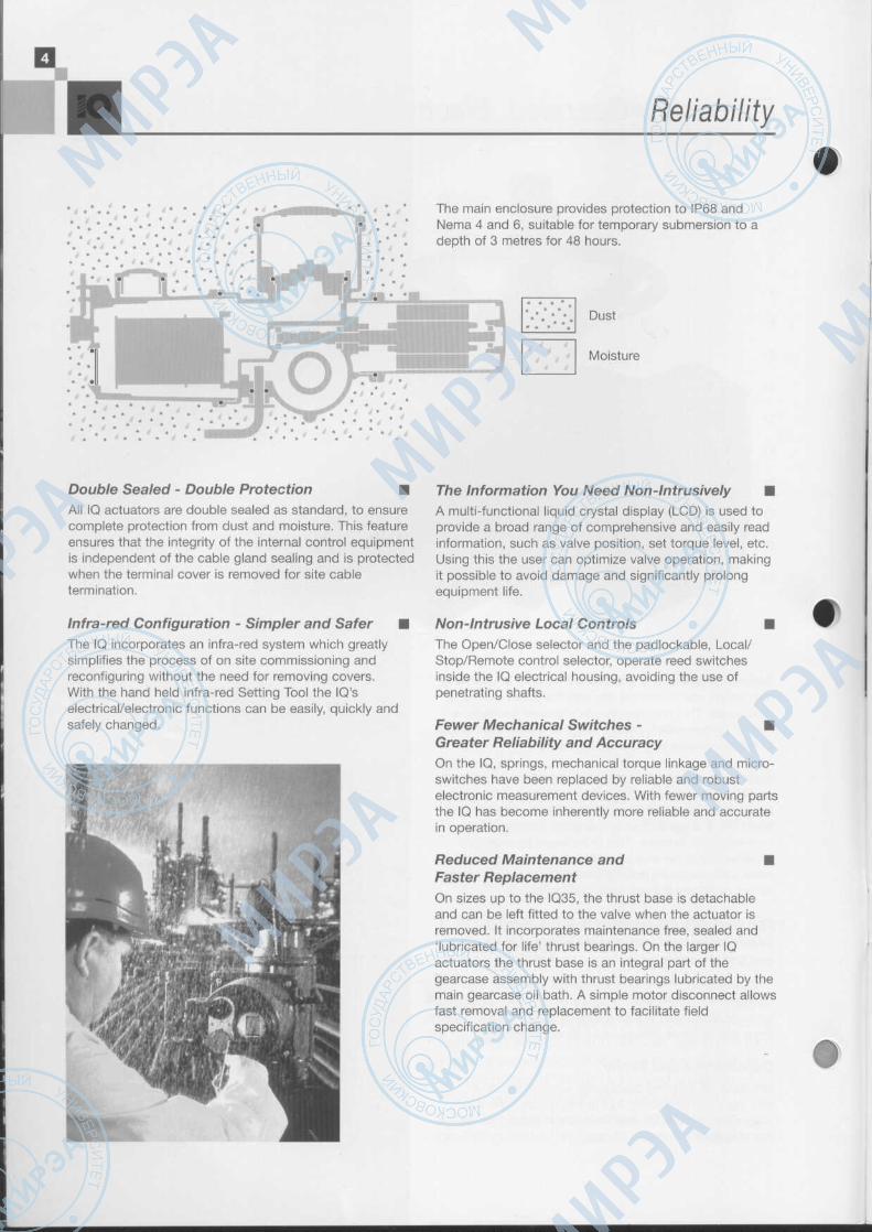
• . ' • " . * . . • . " . • * . -• ' * . * . < * • , *The main enclosure provides protection to IP68 andNema 4 and 6, suitable for temporary submersion to adepth of 3 metres for 48 hours.
Dust
Moisture4t/ »
Double Sealed - Double Protection •All IQ actuators are double sealed as standard, to ensurecomplete protection from dust and moisture. This featureensures that the integrity of the internal control equipmentis independent of the cable gland sealing and is protectedwhen the terminal cover is removed for site cabletermination.
Infra-red Configuration - Simpler and Safer •The IQ incorporates an infra-red system which greatlysimplifies the process of on site commissioning andreconfiguring without the need for removing covers.With the hand held infra-red Setting Tool the IQ'selectrical/electronic functions can be easily, quickly andsafely changed.
The Information You Need Non-lntrusively •A multi-functional liquid crystal display (LCD) is used toprovide a broad range of comprehensive and easily readinformation, such as valve position, set torque level, etc.Using this the user can optimize valve operation, makingit possible to avoid damage and significantly prolongequipment life.
Non-Intrusive Local Controls •The Open/Close selector and the padlockable, Local/Stop/Remote control selector, operate reed switchesinside the IQ electrical housing, avoiding the use ofpenetrating shafts.
Fewer Mechanical Switches - •Greater Reliability and AccuracyOn the IQ, springs, mechanical torque linkage and micro-switches have been replaced by reliable and robustelectronic measurement devices. With fewer moving partsthe IQ has become inherently more reliable and accuratein operation.
Reduced Maintenance and •Faster ReplacementOn sizes up to the IQ35, the thrust base is detachableand can be left fitted to the valve when the actuator isremoved. It incorporates maintenance free, sealed and'lubricated for life' thrust bearings. On the larger IQactuators the thrust base is an integral part of thegearcase assembly with thrust bearings lubricated by themain gearcase oil bath. A simple motor disconnect allowsfast removal and replacement to facilitate fieldspecification change.
Intelligent Actuation Ml
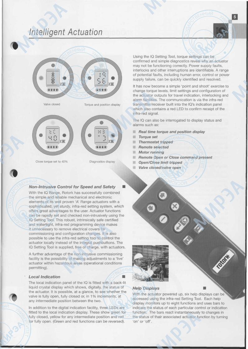
Valve closed Torque and position display
Close torque set to 40% Diagnostics display
Using the IQ Setting Tool, torque settings can beconfirmed and simple diagnostics reveal why an actuatormay not be functioning correctly. Power supply faults,interlocks and other interruptions are identifiable. A rangeof potential faults, including human error, control or powersupply failure, can be quickly identified and resolved.
It has now become a simple 'point and shoot' exercise tochange torque levels, limit settings and configuration ofthe actuator outputs for travel indication, interlocking andalarm facilities. The communication is via the infra-redtransmitter/receiver built into the IQ's indication panelwhich also contains a red LED to confirm receipt of theinfra-red signal.
The IQ can also be interrogated to display status andalarms such as:
* Real time torque and position displayTorque set
• Thermostat trippedRemote selectedMotor runningRemote Open or Close command presentOpen/Close limit trippedValve closed/valve open
Non-Intrusive Control for Speed and Safety •With the IQ Range, Rotork has successfully combinedthe simple and reliable mechanical and electronicelements of its well proven 'A' Range actuators with asophisticated, yet sturdy, infra-red setting system, whichoffers great advantages to the user. Actuator functionscan be rapidly set and checked non-intrusively using theIQ Setting Tool. This robust, intrinsically safe certifiedand watertight, infra-red programming device makesit unnecessary to remove electrical covers forcommissioning and configuration changes. It is alsopossible to use the infra-red setting tool to control theactuator locally instead of the integral pushbuttons. TheIQ Setting Tool is supplied, free of charge, with actuators.
A further advantage of the non-intrusive commissioningfacility is the possibility of making adjustments to a 'live'actuator within hazardous areas (operational conditionspermitting).
Local Indication •The local indication panel of the IQ is fitted with a back-litliquid crystal display which shows, digitally, the status ofthe actuator. It is possible, at a glance, to see whether thevalve is fully open, fully closed or, in 1% increments, atany intermediate position between the two.
In addition to the digital indication facility, three LEDs arefitted to the local indication display. These show green forfully closed, yellow for any intermediate position and redfor fully open. (Green and red functions can be reversed).
Help DisplaysWith the actuator powered up, six help displays canaccessed using the infra-red Setting Tool. Each helpdisplay monitors up to eight functions and uses bars toindicate the status of each particular control or indicationfunction. The bars react instantaneously to changes inthe status of their associated actuator function by turning'on' or 'off'.

Comprehensive Protection
Syncrophase - Prevents Valve Damage •from Faulty WiringRotork has designed Syncrophase to prevent the valvedamage that incorrect power cabling can cause. Sincethere is no simple way of ensuring correct phasesequence prior to switching on an actuator, Syncrophaseautomatic phase rotation correction ensures that the IQ'sthree-phase motor is always presented with the correctphase rotation of the power supply.
Instant Reversal Protection •In the IQ an automatic time-delay circuit prevents theshock loads which may cause unnecessary wear to valvestems and gearboxes when an actuator is ordered toreverse direction 'instantaneously'. The circuit also limitscurrent surges through the contactor.
Motor Protection when Valve Jams •Should a valve jam, the IQ motor is prevented fromoverheating, by the inclusion of a logic circuit which tripsthe contactor when there is no movement within 7seconds following a start signal.
Single Phasing Protection •Also developed to control motor overheating, the IQ'selectronics constantly monitor all three phases of thepower supply. Should one or more phases be lost thecontrol circuit is prevented from energizing the contactors.Local and remote alarm signals of incomplete supply areavailable as standard features.
Thermostatic Protection •A thermostat is embedded in the end windings of themotor, directly sensing the temperature of these windings.This thermostat will trip the actuator control circuit if themotor windings overheat.
Auto Self Test and Diagnosis (ASTD) •Every time the actuator is powered up, it automaticallytests its vital operational circuits and memory devices toensure correct operation. In the unlikely event of a deviceproblem the fault is diagnosed and the informationautomatically presented on Help Screen 7. At the sametime actuator operation can be inhibited to enable siteinvestigation.
H7 ASTD display
Comprehensive Applications
Valve Stem Expansion •The stems of positive seating valves, such as solid orflexible wedge gates may be subject to significantexpansion when used in high service temperatureapplications resulting in damaged or leaking valves. Theeffects of this expansion or contraction may be overcomeby fitting the Rotork temperature compensator to theoutput of the IQ actuator. See publication E152E.
Gearboxes for Part-Turn Valves •IQ actuators can be fitted with part-turn worm and wheelgearboxes to provide increased torque at reduced speedsfor the operation of part-turn valves.
Damper Actuators •Single blade and multi vane dampers can be motorizedeither by direct connection to the damper spindle or bylever arm.
Gearboxes for Multi-Turn Valves •Large or slow moving gate and globe valves can bemotorized through thrust taking bevel or spur gearoperators on which the electric actuator is mounted.
A sizing program for both part-turn and multi-turnapplications is available on both 31/2" floppy disk andCD ROM.
Floor Mounting •Floor stands with upward or downward stubshafts areavailable for coupling, via customer shafts and universaljoints, to remote valves.
Linear Output Drive Assemblies •For applications requiring an actuator with a linear outputa leadscrew arrangement may be fitted to the base of thestandard IQ actuator.
Fireproofing •An intumescent material K-mass™ is moulded to allexternal surfaces of the actuator which enables anotherwise standard IQ to operate for up to thirty minutesin a fire. The advantage of this system is that there is onlya small increase in overall actuator size while retainingaccess to all covers.
For details see publication S310E.
Actuator Drive Couplings
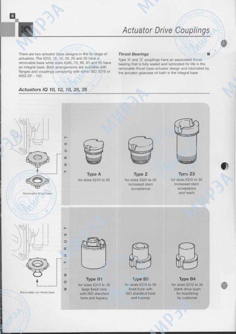
There are two actuator base designs in the IQ range ofactuators. The IQ10, 12, 18, 20, 25 and 35 have aremovable base while sizes IQ40, 70, 90, 91 and 95 havean integral base. Both arrangements are available withflanges and couplings complying with either ISO 5210 orMSSSP- 102.
Thrust Bearings •Type 'A' and 'Z' couplings have an associated thrustbearing that is fully sealed and lubricated for life in theremovable thrust base actuator design and lubricated bythe actuator gearcase oil bath in the integral base
Actuators IQ 10, 12, 18, 25, 35
Type Afor sizes Ю10 to 35
Type Zfor sizes IQ20 to 35
increased stemacceptance
Removable thrust base
Type Z3for sizes IQ10 to 35
increased stemacceptanceand reach
со
э
ОС
I
о
ZRemovable non-thrust base
Type B1for sizes IQ10 to 35
large fixed borewith ISO standardbore and keyway
Type B3for sizes IQ10 to 35
fixed bore withISO standard bore
and keyway
Type B4for sizes IQ10 to 35
blank drive bushfor machiningby customer
f>

11
Actuator Drive Couplings
actuator design. Both the integral and the removablethrust bases are designed to retain all developed thrustreaction forces without any load appearing on theactuator gearcase.
Actuators IQ 40, 70, 90, 91, 95
о'•4̂'wО
CL
D
DC
I
egсо
'елО
Q-
Standard centre columnwith thrust bearing
Type Afor sizes IQ40, 70
and 90
Type Z3for sizes IQ40, 70, 90
and 95 increasedstem acceptance
and reach
z
О
Non-thrustcentre column
Type B1for sizes IQ40, 70 and 90
large fixed borewith ISO standardbore and keyway
Type B3for sizes IQ40, 70, 90and 91 fixed bore with
ISO standard boreand keyway
Type B4for sizes IQ40, 70, 90
and 91 blank drivebush for machining
by customer

Intelligent Communication
IThe IQ Communicator •The IQ communicator is a weatherproof hand heldcomputer supplied with a dedicated Rotork softwarepackage. It allows the user to interrogate any IQ actuator,giving access to sophisticated valve actuator diagnosticsand configuration via an infra-red link. The link isconnected to the IQ Communicator and attached to theIQ actuator indication window. An intrinsically safe IQcommunicator is available.
When the IQ actuator is fitted with the optional DataLogger, historical information such as operator actionsand output torque profiles can be downloaded to the IQCommunicator for analysis.
The IQ Communicator also carries out all of the functionsof the IQ Setting Tool, displaying the commands in plainlanguage on its 80 character display. Both the IQCommunicator and the Data Logger PCB are optionalextras. For further information see publication E111E.
Data Logger Viewer •This software which runs under Windows 3.1x, 95 andNT enables the user to load and examine IQ actuatordata that has been downloaded from the IQ Data Logger.The enhanced file storage and graphic display facilitiesenable the user to build up a comprehensive record forhis motor operated valves. See publication E111E forfurther details.
Intelligent Communication
91j, F .
476.12:19:35.75TueOct?l 1997
TRQPWMTT"ESMPWMVT i| | j
RS_TRORSJR
RS.FOlT I iRS_ESMEE_ERR iRS.PAKTT MJE
List Window Help
mmGOOD12V
OIL
[ШШМЛЛШИШШШИМ- S,«s:D.\DATA\BR*NT3:lDatalogger Statistics LogClose Limit switch trip: 15:22:15.00 Tue Febl? 1998Close Limit switch reset: 14:52:30.25 Tue Febl 7 1998Open Limit switch trip: 15:06:29.00 Tue Feb 17 1998Opeh Limit switch reset: 15:08:15.25 Tue Febl7 1998Clockwise contactor operations: 133Anti-Clockwise contactor operations: 130
I Event: -11/1023
T.me
Г RS_PAKГ RSJESM
Г RS_TRO
i RSJR
RS_FOL
MAINSGOOO
GOODVRAW
BATLOW
: 14:52:25. 75 Т
«"LOCAL
Г REMOTE
ff RMAIN
Г TBPESD
Г COLMOV
Г MRELAY
f G00024V
TTRQPWM
Position: 0
e Febl 7 1998 Tor
f LCLOSE
Г RCLOSE
rciL
PPLCOB
f" MOVECW
("THERM
f~GOOD12V
Г ESMPWM
e:60
LOPEN
ROPEN
OIL
PLOOB
MOVEACW
VLFPWM
GOOD5V
EE_ERR
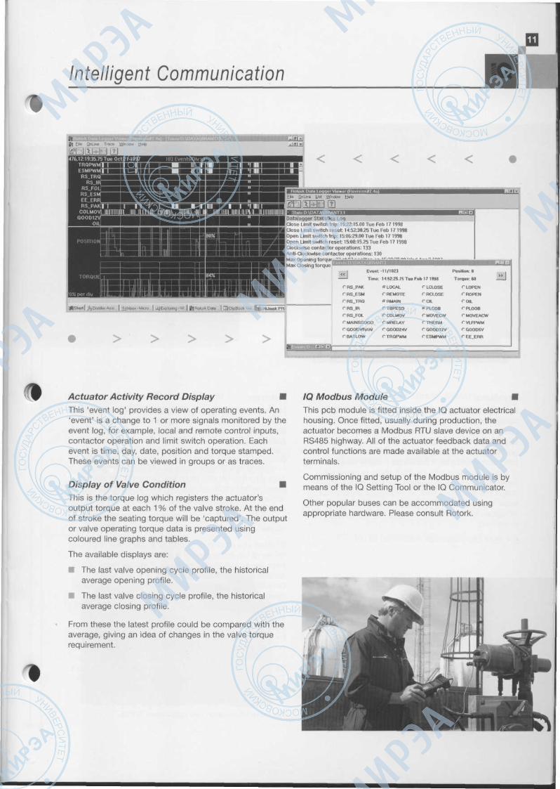
Actuator Activity Record Display •This 'event log' provides a view of operating events. An'event' is a change to 1 or more signals monitored by theevent log, for example, local and remote control inputs,contactor operation and limit switch operation. Eachevent is time, day, date, position and torque stamped.These events can be viewed in groups or as traces.
Display of Valve Condition •This is the torque log which registers the actuator'soutput torque at each 1 % of the valve stroke. At the endof stroke the seating torque will be 'captured'. The outputor valve operating torque data is presented usingcoloured line graphs and tables.
The available displays are:
si The last valve opening cycle profile, the historicalaverage opening profile.
• The last valve closing cycle profile, the historicalaverage closing profile.
From these the latest profile could be compared with theaverage, giving an idea of changes in the valve torquerequirement.
/Q Modbus Module •This pcb module is fitted inside the IQ actuator electricalhousing. Once fitted, usually during production, theactuator becomes a Modbus RTU slave device on anRS485 highway. All of the actuator feedback data andcontrol functions are made available at the actuatorterminals.
Commissioning and setup of the Modbus module is bymeans of the IQ Setting Tool or the IQ Communicator.
Other popular buses can be accommodated usingappropriate hardware. Please consult Rotork.
Communication Systems
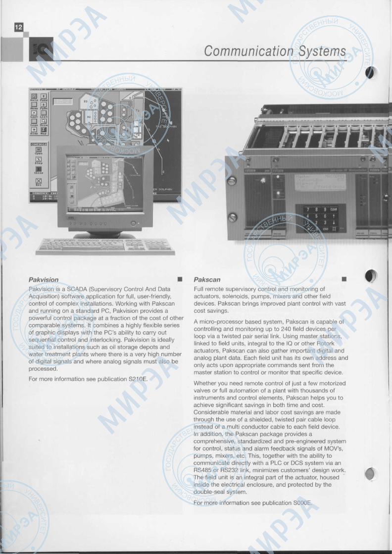
Pakvision •Pakvision is a SCADA (Supervisory Control And DataAcquisition) software application for full, user-friendly,control of complex installations. Working with Pakscanand running on a standard PC, Pakvision provides apowerful control package at a fraction of the cost of othercomparable systems. It combines a highly flexible seriesof graphic displays with the PC's ability to carry outsequential control and interlocking. Pakvision is ideallysuited to installations such as oil storage depots andwater treatment plants where there is a very high numberof digital signals and where analog signals must also beprocessed.
For more information see publication S210E.
Pakscan •Full remote supervisory control and monitoring ofactuators, solenoids, pumps, mixers and other fielddevices. Pakscan brings improved plant control with vastcost savings.
A micro-processor based system, Pakscan is capable ofcontrolling and monitoring up to 240 field devices perloop via a twisted pair serial link. Using master stations,linked to field units, integral to the IQ or other Rotorkactuators, Pakscan can also gather important digital andanalog plant data. Each field unit has its own address andonly acts upon appropriate commands sent from themaster station to control or monitor that specific device.
Whether you need remote control of just a few motorizedvalves or full automation of a plant with thousands ofinstruments and control elements, Pakscan helps you toachieve significant savings in both time and cost.Considerable material and labor cost savings are madethrough the use of a shielded, twisted pair cable loopinstead of a multi conductor cable to each field device.In addition, the Pakscan package provides acomprehensive, standardized and pre-engineered systemfor control, status and alarm feedback signals of MOV's,pumps, mixers, etc. This, together with the ability tocommunicate directly with a PLC or DCS system via anRS485 or RS232 link, minimizes customers' design work.The field unit is an integral part of the actuator, housedinside the electrical enclosure, and protected by thedouble-seal system.
For more information see publication SOOOE.

Communication Systems
Ш
Pakscan HE Direct Operator Panel •The Pakscan HE OOP provides push-button control of upto 240 valves on one system. The push-button controlwith display panel gives clear and concise information onvalve status and permits full plant operation. The heart ofthe system is a range of multi-channel modules that areable to control up to 4 actuators using individual controlsfor each of the actuator channels. Alternative modulespermit the control of positioning actuators, and whenused in conjunction with General Purpose Field Units, thecontrol of pumps, mixers, compressors etc.
For further information see publication S111E.
Pakscan IIS Sequencer Master Station •The Pakscan IIS master station encompasses the provenfeatures of the Pakscan 2 wire control system with thelogic and programmability more commonly found in aPLC, to provide a full featured sequence and interlockcontrol package. Easily programmed by 'fill in the box'actions the Pakscan IIS is quickly ready to run your plant.
Located in the field close to the process, Pakscan IISpermits control and monitoring of up to 32 field units.
For further information see publication S112E.

The IQ Range of Actuators
f\
1 Separately sealed terminal compartment ensuresthe integrity of the electrical equipment even when theterminal cover is removed during site wiring.
2 Local controls and 'padlockable Local/Stop/Remoteselector switch operate internal reed switches, avoidingpenetrating shafts which would have to be sealed toprevent moisture ingress.
3 All actuator settings and diagnostics are madethrough the sealed indication window. It is not necessaryto remove electrical covers exposing the integral controlson site.
4 Low inertia high torque motor. The motor producespeak torque rapidly after starting but with very littleoverrun when de-energized. The winding thermostatprovides accurate temperature sensing independent ofambient temperature conditions to optimize the motor'sthermal capacity.
The motor drive includes a lost motion 'hammerblow' toassist in unseating tightly shut valves.
5 Sense winding in the stator to measure actuatortorque via patented solid state circuitry with temperaturecompensation - avoiding the use of springs, switches andlevers for torque control.
6 Single worm and wheel drive running in an oil bathfor maximum life with ambient temperature tolerance.
7 Hall effect magnetic pulse system accuratelymeasures and controls the stroke of the actuator withoutusing gears and switches.
8 Direct drive handwheel (or independently gearedhandwheel on larger sizes) to provide reliable emergencymanual operation in the event of a power supply failure.
9 Low speed *padlockable hand/auto clutch for safeoperation even when the motor is running. Note: poweroperation always has preference unless hand/auto leveris purposely locked into 'hand drive'. Lost motion'hammerblow' effect is provided with both direct andindependently geared handwheels.
10 Thrust base for type 'A' couplings lubricated for lifeand detachable, up to size IQ35, to allow actuatorremoval without disturbing the valve position. On sizesIQ40 and above the thrust base is an integral part of thegearcase assembly.
11 Easily removable drive bushing for machining to suitvalve stem for convenient valve adaptation.
12 Motor shaft and worm shaft separate to facilitateactuator speed change.
'Suitable for 6mm/1A inch padlock

The /Q Range of Actuators

IQ Actuators and Second Stage Gearboxes
IQ Actuators with Second Stage Worm and •Wheel GearboxesThe following types of worm and wheel gearboxes areavailable for use with IQ actuators:-
Type IW for applications requiring up to 90° input.
Type MTW for applications requiring up to 360° input.
The IW and MTW ranges are of similar design exceptthat the IW has a 90° wormwheel quadrant withadjustable output stops for 90°± 5° while the MTW rangehas a full 360°output and no end stops.
The IQ/second stage worm and wheel combinationsprovide output torques up to 270,000 Nm (200,000 Ft Ibf)with 90° travel times in the range of 3 - 675 seconds.
Construction тThe worm and quadrant gearing with self locking ratio ishoused in a robust cast iron gearcase with 0-ring sealsfor all input and output interfaces. Gearing is lubricated forlife, with grease for the type IW range and oil for theMTW range.
The input wormshaft is arranged for key drive from theactuator stem nut and is supported in angular contactbearings to take the radial and axial loads. The outputdrive is in the form of a removable insert in the gearquadrant. The output drive assembly is supported in plain-journal bearings designed to take the gear separatingforces. Side loads which may arise in the driven unit mustbe catered for by the provision of a suitable externalbearing arrangement.
The adjustable mechanical stops provided in the type IWgearboxes are in the form of high tensile steel socket setscrews with hexagon lock nuts and are designed to takethe rated torque output of the actuator/gearboxcombination.
The gearbox mounting bases are available to ISO 5210 orISO 5211 as appropriate (or equivalent UNO Standards).Gearboxes are provided with a removable output drivecoupling for machining by the valve manufacturer to suitthe valve shaft. Actuator/gearbox combinations arenormally supplied completely assembled and tested asclose-coupled units. However, where applications requirethe valve to be driven from remotely mounted actuators, itis recommended that the second stage gearbox is directlymounted on the valve and only the actuator is remotelymounted. This arrangement gives the advantage that theextension drive shafting only has to transmit actuatoroutput torque. For these applications the gearbox shouldbe ordered with the actuator mounting flange omitted.
The materials of the second stage gear boxes describedabove are suitable for ambient temperatures of -40°C to+95°C and the enclosure is suitable for outdoor use non-submerged. Apply to Rotork for submerged duty ortemperatures below -40°C.
As standard, the gearboxes are despatched painted tothe same colour as the IQ actuator.
The full range of actuator/gearbox performance and asizing selection programme is available on 31/2" floppydisc or CD ROM.
с

IQ Actuators and Second Stage Gearboxes
IQ Actuators with Second Stage Multi-turn •GearboxesThe following types of multi-turn gearboxes are availablefor use with IQ actuators.
IB bevel gearboxes have ratios in the order of 2:1 to 8:1and torque outputs in the range of 300 Nm (225 Ft Ibf) to8,638 Nm (6,375 Ft Ibf). The thrust bearing assemblies inthe base withstand the thrust reaction of the valve stem.An easily removable aluminium bronze drive bush formachining to suit the valve stem is supplied. Thrustratings are between 53 kN (12,000 Ibf) and 1555 kN(350,000 Ibf).
IS spur gearboxes have ratios in the order of 2:1 to 24:1with torque outputs in the range of 400 Nm (300 Ft Ibf) to43,360 Nm (32,000 Ft Ibf). These gearboxes have thrustbearing assemblies and removable drive bushes thesame as type IB but the thrust ratings are in the range of53 kN (12,000 Ibf) to 2222 kN (500,000 Ibf).
The use of the bevel gearboxes will result in a 'sidemounting' orientation of the actuator for valves withvertical stems while the spur gearboxes will give a 'topmounting' orientation for the same type of application.Smaller actuator/spur gear combinations may not besuitable for rising stem valve applications as there maynot be clearance for the valve stem in the open position.
The gearboxes are available with cover tubes, whenrequired, to protect the rising stem of the valve above thebody of the gearbox.
Performance Summary
Performance Data
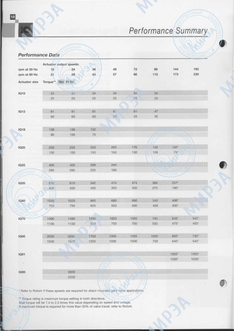
Actuator output speeds
rpm at 50 Hz
rpm at 60 Hz
18
21
24
29
36
43
48
57
72
86
96
115
144
173
192
230
Actuator size Torque** Nm Ft Ibf
IQ10 34
25
34
25
34
25
34
25
34
25
34
25
IQ12 81
60
81
60 60 60
61
45
47
35
IQ18 108
80
136
100
102
75
IQ20 203
150
203
150
03
150
203
150
176
130
142
105
102*
75*
IQ25 400
295
400
295
298
220
244
180
IQ35 610
450
610
450 400
474
350
474
350
366
270
257*
190*
IQ40 1020
750
1020
750
845
625
680
500
680
500
542
400
406*
300*
IQ70 1490
1100
1490
1100
1290
950
1020
750
1020
750
745
550
645*
475*
542*
400*
IQ90 2030
1500
2030
1500
1700
1250
1355
1000
1355
1000
1020
750
865*
640*
730*
540*
IQ91 1355*
1000*
1355*
1000*
IQ95 3000
2200
* Refer to Rotork if these speeds are required for direct mounted gate valve applications.
** Torque rating is maximum torque setting in both directions.Stall torque will be 1.4 to 2.0 times this value depending on speed and voltage.If maximum torque is required for more than 20% of valve travel, refer to Rotork.

Performance Summary
Mechanical Data
Actuator size IQ10 IQ20
IQ12 IQ25
IQ18
IQ35 IQ40 IQ70 IQ90 IQ91 IQ95
Flange size ISO 5210 F10 F14 F16 F25 F25 F30* F25 F30
MSSSP-102 FA10 FA14 FA16 FA25 FA25 FA30* FA25 FA30
Group 'A' couplings (thrust)
Thrust rating kN
Ibf
44 100 150 220 220 334 N/A 445
10,000 22,480 33,750 50,000 50,000 75,000 N/A 100,000
Stem acceptance diameter
Type 'A (maximum)
Rising mm
ins
32 38 54 64 70 70 N/A N/A
ГА Г/2 2V» 2'/г 23A 23Л N/A N/A
Non-rising mm
ins
26
1
32 45
13/4
51
2
57
21/,
57
2'/4
N/A
N/A
N/A
N/A
Type 'Z' (maximum)
Rising mm
ins
51 67 73 83 83 N/A
2 2Ve 27/в 31A 31A N/A
83
Non-rising mm
ins
38 51
2
57
21Л
73 73
2Ve 2Ve
N/A
N/A
73
2Ve
Group 'B' couplings (non-thrust)
Bore diameter
Type 'B1' (fixed bore) mm 42tt 60tt 80tt 100 100 120 100 N/A
Type 'B3' (fixed bore) 20t 30t 40t 50 50 50 50 N/A
Type 'B4' (maximum) mm
ins
20t3/4
30t
V/,
44t13/4
50
2
60
21/4
60
21Л
60
2'/4
N/A
N/A
Handwheel ratio Standard
Optional
Direct
12:1
Direct
13.5:1
Direct
22.5:1
Direct
20:1
or
10:1
15:1
30:1
15:1
45:1
15:1
30:1
15:1
45:1
* IQ90 with B3 and B4 couplings have flange size F25.t For actuator sizes IQ10 to IQ35 when required to drive shafts or stems having any axial movement, a type 'A' coupling must be used.tt Please specify coupling type 'B1' Т for rising rotating stem applications.
Performance Summary
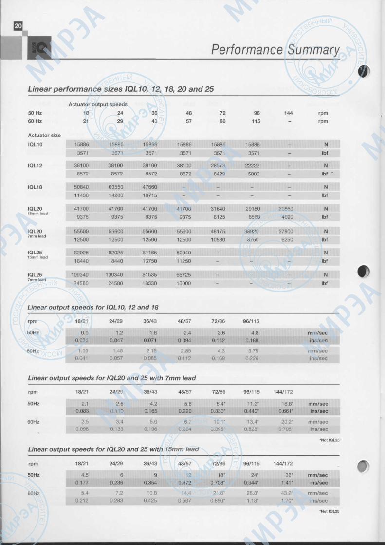
Linear performance sizes IQL10, 12, 18, 20 and 25
Actuator output speeds
50 Hz
60 Hz
18
21
24
29
36
43
48
57
72
86
96 144
115
rpm
rpm
Actuator size
IQL10
IQL12
IQL18
IQL2015mm lead
IQL207mm lead
IQL2515mm lead
IQL257mm lead
15886
3571
38100
8572
50840
11436
41700
9375
55600
12500
82025
18440
109340
24580
Linear output speeds
rpm
50Hz
60Hz
Linear
rpm
50Hz
60Hz
.
18/21
0.90.035
1.050.041
output speeds
18/21
2.10.083
2.50.098
15886
3571
38100
8572
63550
14286
41700
9375
55600
12500
82025
18440
109340
24580
for IQL10,
24/29
1.20.047
1.450.057
for IQL20
24/29
2.80.110
3.4
0.133
15886
3571
38100
8572
47660
10715
41700
9375
55600
12500
61165
13750
81535
18330
12 and 18
36/43
1.80.071
2.150.085
and 25 with
36/43
4.20.165
5.0
0.196
15886
3571
38100
8572
-
-
41700
9375
55600
12500
50040
11250
66725
15000
48/57
2.40.094
2.850.112
7mm lead
48/57
5.60.220
6.70.264
15886
3571
28573
6429
-
-
31640
8125
48175
10830
-
-
72/86
3.60.142
4.30.169
72/86
8.4*
0.330*
10.1*0.398*
15886
3571
22222
5000
. _
-
29180 20860
6560 4690
38920 27800
8750 6250
- -
SSSSSm
96/115
a,« .•5.75
0.226
96/115 144/172
11.2* 16.8*0.440* 0.661*
13.4* 20.2*0.528* 0.795*
N
Ibf
N
Ibf
N
Ibf
N
Ibf
N
Ibf
N
Ibf
N
Ibf
mm/secins/sec
mm/secins/sec
mm/secins/sec
mm/secins/sec
•
'Not IQL25
Linear
rpm
50Hz
60Hz
output speeds
18/21
4.5
5.40.212
for IQL20
24/29
Ё6
0.236
7.20.283
and 25 with
36/43
90.354
10.80.425
15mm lead
48/57
120.472
14.40.567
72/86
18*0.708*
21.6*0.850*
96/115 144/172
24* 36*0.944* 1.41"
28.8* 43.2*1.13* 1.70*
mm/secins/sec
mm/secins/sec
•Not IQL25
f
Standard Specification
3 phaseinductionmotor
PositionProcessor
sitionmits
л ^<
Set positionlimits
Position
Current
fra-redInterlace
Processor
Torque
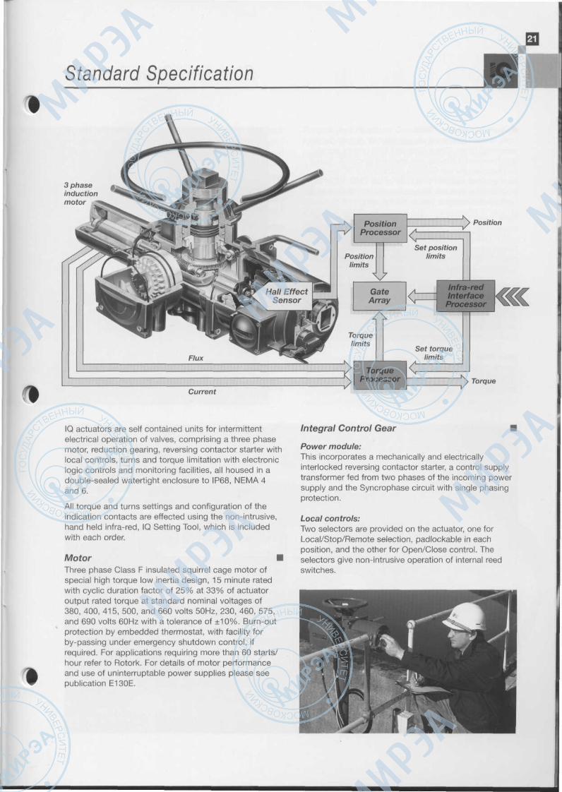
IQ actuators are self contained units for intermittentelectrical operation of valves, comprising a three phasemotor, reduction gearing, reversing contactor starter withlocal controls, turns and torque limitation with electroniclogic controls and monitoring facilities, all housed in adouble-sealed watertight enclosure to IP68, NEMA 4and 6.
All torque and turns settings and configuration of theindication contacts are effected using the non-intrusive,hand held infra-red, IQ Setting Tool, which is includedwith each order.
Motor •Three phase Class F insulated squirrel cage motor ofspecial high torque low inertia design, 15 minute ratedwith cyclic duration factor of 25% at 33% of actuatoroutput rated torque at standard nominal voltages of380, 400, 415, 500, and 660 volts 50Hz, 230, 460, 575,and 690 volts 60Hz with a tolerance of ±10%. Burn-outprotection by embedded thermostat, with facility forby-passing under emergency shutdown control, ifrequired. For applications requiring more than 60 starts/hour refer to Rotork. For details of motor performanceand use of uninterruptable power supplies please seepublication E130E.
Integral Control Gear •
Power module:This incorporates a mechanically and electricallyinterlocked reversing contactor starter, a control supplytransformer fed from two phases of the incoming powersupply and the Syncrophase circuit with single phasingprotection.
Local controls:Two selectors are provided on the actuator, one forLocal/Stop/Remote selection, padlockable in eachposition, and the other for Open/Close control. Theselectors give non-intrusive operation of internal reedswitches.

Standard Specification
Remote input/relay PCS:Opto-isolator interfaces are provided for remote 'positiveswitching' Open, Close, Stop and ESD control signals,and Thermostat Bypass and Interlock functions. Thesecan be internally fed from the actuator 24V DC supply orfrom external supplies of 20-60V or 60-120V AC or DC.Four latching contacts are provided each independentlyconfigurable to signal one of the following:
Valve opening, closing, moving (continuous or pulsingsignal), fully open, fully closed or intermediate positions,motor tripped on torque in mid travel, motor tripped ontorque going open, or motor tripped on torque goingclosed, pre-set torque exceeded, motor stalled, batterylow, actuator being operated by handwheel.
Each contact is selectable to either 'normally open' or'normally closed' and rated at 5A, 250V AC, 30V DC.The Emergency Shut Down (ESD) facility provides for aremote, active high signal to open or close the valve,which will override any local Open or Close signals andthe motor thermostat if suitably selected.
Main PCB:Incorporates the gate array control for the actuatortogether with infra-red receiver for external non-intrusivesettings.
Ambient Temperatures and Enclosure Options •Actuators are available with the following main enclosuretypes for which the ambient working temperature rangesare as indicated:
WT:Standard watertight, IP68, NEMA 4 and 6.-30°C to +70°C (-22T to +158T)
* Alternative for -40°C to +70°C (-40T to +158T)
CSA WT:Canadian Standard Association approved wiring andcomponents complying with CSA Enclosure 4.-30°C to +70°C (-22T to +158T).
* Alternative for -40°C to +70°C (-40T to +158T)
CSA EP:Canadian Standard Association approved for Class 1,Division 1, Groups С & D hazardous areas.-30°C to +40°C (-22T to +104T)
* Alternative for -40°C to +40°C (-40T to +104T)
* These alternatives require a change to some actuator components andshould be specified if required.
•A
Standard Specification
Torque and Position Control •Torque and turns are adjustable as follows:
Position setting range: 2.5 to 100,000 turns, withresolution to 15° of actuator output.
Torque setting: 40% to 100% rated torque.
Electronic 'latching' is provided for the torque sensingsystem to inhibit 'torque off' during unseating or duringstarting in mid travel against high inertia loads. A 'jammedvalve' protection circuit de-energizes the motor if nomovement occurs after a few seconds from receipt of asignal to open or close.
When power to the actuator is isolated, all settings areretained in an EEPROM. In the event of manual operationof the valve during isolation or loss of the power supply abattery provides power to the internal position monitoringtransmitter to update the valve position data in theEEPROM. The battery also drives the LCD display,without backlighting, and the four latching contacts of theremote input/relay PCB while the power to the actuator isnot available. Minimum battery life is 7 years.
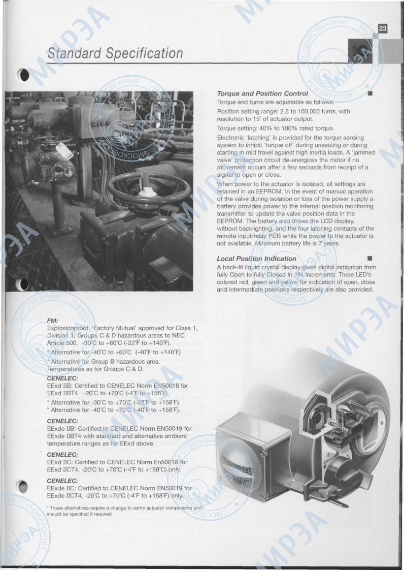
Local Position Indication •A back-lit liquid crystal display gives digital indication fromfully Open to fully Closed in 1% increments. Three LED'scolored red, green and yellow for indication of open, closeand intermediate positions respectively are also provided.
FM:Explosionproof, 'Factory Mutual' approved for Class 1,Division 1, Groups С & D hazardous areas to NECArticle 500. -30°C to +60°C (-22T to +140T).
* Alternative for -40°C to +60°C (-40T to +140T)
* Alternative for Group В hazardous area.Temperatures as for Groups С & D.
CENELEC:EExd IIB: Certified to CENELEC Norm EN50018 forEExd IIBT4. -20°C to +70°C (-4T to +158T).
* Alternative for -30°C to +70°C (-22T to +158T)* Alternative for -40°C to +70°C (-40T to +158T).
CENELEC:EExde IIB: Certified to CENELEC Norm EN50019 forEExde IIBT4 with standard and alternative ambienttemperature ranges as for EExd above.
CENELEC:EExd IIC: Certified to CENELEC Norm En50018 forEExd IICT4, -20°C to +70°C (-4T to +158°C) only.
CENELEC:EExde IIC: Certified to CENELEC Norm EN50019 forEExde IICT4, -20°C to +70°C (-4T to +158T) only.
* These alternatives require a change to some actuator components andshould be specified if required.

Standard Specification
Monitor Relay •A relay with a volt-free changeover contact for monitoringactuator electrical availability. Contact rating 5A 250V AC,30V DC.
Wiring •Jig built harnesses of individually numbered strandedconductors, tropical grade PVC insulated, connectinternal components to the sealed terminal block. Theremainder of the internal wiring is color coded ribboncable.
Terminals •Separately sealed compartment containing segregatedmetric thread M5 power and M4 control terminals.Terminal screws and washers are supplied with theactuator. All internal control connections to the printedcircuit boards are via plugs and sockets. The terminal boxcover carries a terminal identification code card. Aninstruction & maintenance handbook and wiring diagramare enclosed with each actuator.
Conduit Entries •Three threaded conduit entries are supplied with thefollowing alternative sizes available as standard:
1, x M40 and 2 x M25 metric to BS3643.
1 x ГА" and 2 x 1" ASANPT.
1 xPG29and2xPG16.
Where metallic cable glands or conduit are to be usedwith actuators that may be subject to salt water spray, itis recommended that the cable gland material should beone that is compatible with aluminium to avoidelectrolytic action.
Valve Actuator Interface •The range of IQ actuators is available with mounting baseand output drive couplings conforming to internationalstandard ISO 5210 or USA standard MSS SP-102 (seePublications E140-1E, E141-1E, E142-1E, E143E,E144E, E145E, E146E and E147E for dimensions). Theapplications for which the various types of couplings havebeen designed are outlined as follows and the appropriatedata concerning stem acceptance diameters are given inthe table on page 19.
Group A Couplings •Actuators are provided with a base assemblyincorporating a thrust bearing to take the thrust reactioninvolved in the operation of threaded stem valves anda detachable coupling for machining by the valvemanufacturer to suit the valve stem. Type 'Z' couplingsallow acceptance of larger diameter valve stems.
Group В Couplings •Actuators are suitable for torque only applications suchas the operation of threaded stem valves incorporatingtheir own thrust bearings or for driving second stagegearboxes. The couplings are as designated in ISO 5210and MSS SP-102.

Standard Specification
Type 'B1' coupling has a large fixed-dimension bore andkeyway for coupling to the thrust nut assembly of a risingstem valve.
Type 'B3' coupling has a fixed-dimension bore andkeyway.
Type 'B4' coupling is detachable for machining by thevalvemaker to suit the valve stem.
Manual Operation •To engage handwheel operation, a hand/auto lever isprovided which can be locked in the hand or autopositions using a 6mm (1A") diameter hasp padlock (notsupplied by Rotork). Energization of the motorautomatically re-engages power operation unless thelever has been locked in the hand position.
A direct acting top mounted handwheel is provided asstandard on actuator sizes IQ10 - IQ40. A geared sidemounted handwheel is provided as standard on actuatorsizes IQ70 and larger and is available as an optionalextra on sizes IQ18 - IQ40.
Standard Finish •Actuators up to size IQ40 are finished in polyester powdercoating, color charcoal grey.
Actuators size IQ70 and above are finished in air driedurethane reinforced synthetic alkyd resin color, charcoalgrey.
For full specification of paint finish see publication E151E.
Design Life •For isolating duty, torque ratings of actuators are basedon a minimum maintenance free life of 10,000 open/close/open cycles assuming max. seating torque at stroke endand an average of 1/3 max. seating torque during stroke.
For modulating duty see IQM Range, publication E410E.
Vibration •Standard IQ Range actuators are suitable for applicationswhere vibration severity does not exceed the following:
Plant induced: Where the cumulative level of all vibrationwithin the frequency range of 10 to 1000Hz is less thanIGr.m.s.
Shock: 5g peak acceleration.
Seismic: Frequency range 1 to 50Hz, 2g acceleration if itis to operate during and after the event. 5g if it is onlyrequired to maintain structural integrity.
Where excessive plant induced vibration is anticipated,separate IQ controls (see page 27) or mounting theactuator remote from the valve and driving to it throughextension shafting incorporating vibration absorbingcouplings may provide a satisfactory solution.
Electromagnetic Compatibility •The actuators conform to the requirements of theEconomic Community EMC Directive 89/336/EEC asamended by 92/31/EEC.
Noise •Independent tests have shown that at 1 metre generatednoise did not exceed 61db(A).
Optional Features
:olo
mat
ic
о.0об
Folo
mat
ic
о>О)0)
3гагаQ О P
aksc
ar
СЛZ5О
СЛ i-D аз
_а .с
Е°2 0
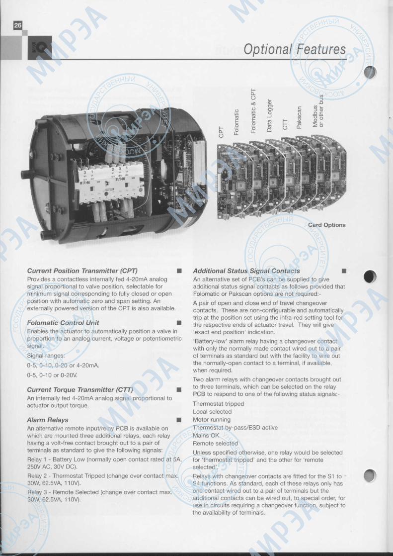
Card Options
Current Position Transmitter (CPT) •Provides a contactless internally fed 4-20mA analogsignal proportional to valve position, selectable forminimum signal corresponding to fully closed or openposition with automatic zero and span setting. Anexternally powered version of the CPT is also available.
Folomatic Control Unit •Enables the actuator to automatically position a valve inproportion to an analog current, voltage or potentiometricsignal.
Signal ranges:
0-5, 0-10, 0-20 or 4-20mA.
0-5, 0-10orO-20V.
Current Torque Transmitter (CTT) •An internally fed 4-20mA analog signal proportional toactuator output torque.
Alarm Relays •An alternative remote input/relay PCB is available onwhich are mounted three additional relays, each relayhaving a volt-free contact brought out to a pair ofterminals as standard to give the following signals:
Relay 1 - Battery Low (normally open contact rated at 5A,250V AC, 30V DC).
Relay 2 - Thermostat Tripped (change over contact max.SOW, 62.5VA, 110V).
Relay 3 - Remote Selected (change over contact max.SOW, 62.5VA, 110V).
Additional Status Signal Contacts •An alternative set of PCB's can be supplied to giveadditional status signal contacts as follows provided thatFolomatic or Pakscan options are not required:-
A pair of open and close end of travel changeovercontacts. These are non-configurable and automaticallytrip at the position set using the infra-red setting tool forthe respective ends of actuator travel. They will give'exact end position' indication.
'Battery-low' alarm relay having a changeover contactwith only the normally made contact wired out to a pairof terminals as standard but with the facility to wire outthe normally-open contact to a terminal, if available,when required.
Two alarm relays with changeover contacts brought outto three terminals, which can be selected on the relayPCB to respond to one of the following status signals:-
Thermostat trippedLocal selectedMotor runningThermostat by-pass/ESD activeMains OKRemote selected
Unless specified otherwise, one relay would be selectedfor 'thermostat tripped' and the other for 'remoteselected'.
Relays with changeover contacts are fitted for the S1 to •S4 functions. As standard, each of these relays only hasone contact wired out to a pair of terminals but theadditional contacts can be wired out, to special order, foruse in circuits requiring a changeover function, subject tothe availability of terminals.

Optional Features
Interrupter Timer •This feature gives automatic pulsed operation of a valveto reduce the effective speed of travel. The timer can beconfigured to operate over a percentage of travel in theopening and closing directions and the length of each'on' and 'off' pulse is also configurable in the range of 2sees, to 99 sees.
Pakscan Interface •An internally mounted Pakscan field unit for remotecontrol and status indication over a two-wire serial link,see publication SOOOE.
Modbus Module •The Modbus Module may be included in the IQ actuatorto provide direct serial communications of all the actuatorcontrol functions and feedback data. This informationis made available at the actuator terminals on an RS485data highway. The communications protocol used toaccess this information is Modbus RTU. System variablessuch as unit address and data baud rate areprogrammable over the infra-red data link, seepublication E121E.
Negative Switching Remote Controls •Suitability for negative switching is achieved by fitting analternative input module.
Data Logger •This is an optional extra electronic card that can either besupplied with the actuator or retrofitted at a later date.When the data logger is fitted to the IQ actuator it ispossible to download historical actuator performancedata to the Communicator for subsequent analysis. Forfurther information please see publication E111E.
Separate IQ Controls •Where extremely high temperatures or vibration levels inexcess of those listed on page 25 exist, a bulkheadmounting IQ control module, suitable for use with up to15 metres of cable between the actuator and the controlmodule, is available. This unit comprises the reversingcontactors, control power supply, control pcb's, localcontrols and the standard led display in a double sealedenclosure. All the standard IQ control options areavailable and the unit is commissioned using thestandard IQ Setting Tool. Enclosures are as the standardrange of IQ actuators.
Food Grade Lubricant •When requested IQ actuators may be supplied with thegearcase filled with Hydra Lube GB Heavy food gradelubricant.
company address telephone telefax
EUROPERotork Motorisation SA Urbaparc 3, 75 rue Rateau
93127 La Courneuve CEDEX, FRANCE(01)43111550 (01)48354254
Rotork Controls (Deutschland) GmbH
Rotork Controls (Italia) Sri
Rotork BV
Rotork Controls Ltd (Moscow Office)
Rotork Controls (Espana) S.L.
Rotork Controls Ltd
AMERICASRotork Controls (Canada) Ltd
Rotork Controls (Canada) Ltd
Rotork Controls Inc
Rotork Controls Inc
Rotork Controls de Venezuela SA
MIDDLE EASTRotork Arabia Limited
Rotork Africa (Pty) Ltd
FAR EASTRotork Controls Shanghai Office
Rotork Controls Beijing Office
Rotork Ltd
Rotork Controls (India) Ltd
Rotork Controls (Singapore) Pte LtdIndonesia Office
Rotork Controls (Korea) Co. Ltd
Rotork Malaysia Sdn Bhd
Rotork Controls (Singapore) Pte Ltd
Rotork Thailand Ltd
Postfach 648, 40706 HildenGERMANY
Via De Vecchi 19,20090 Assago (Ml), ITALY
PostbuS 3597, 3003 AN RotterdamTHE NETHERLANDS
10391 8 MOSCOWUlitsa Ogareva 5 (Room 413), RUSSIA
Ctra. Barrika-Sopelana 948620 Barrika-Vizcaya, SPAIN
Bath, BA1 3JQENGLAND
#1 -2, 5650 Tomken Road, MississaugaOntario L4W 4P1 , CANADA
#9, 820 - 28th Street NECalgary, Alberta T2A 6K1 , CANADA
1 9 Jet View Drive, RochesterNY 14624 -4903, U.S.A
Suite 368, 6776 Southwest FreewayHouston, Texas 77074, U.S.A.
Calle Las Escuelas #15, Urb. Campo AlegreCARACAS 1060, VENEZUELA
P.O. Box 2756Dammam 31461, SAUDI ARABIA
P.O Box 1 78Edenvale 1610, SOUTH AFRICA
Room 1105, Suite C, Orient Int'l Building, 85 Lou Shan Guan RoadShanghai 200336, PEOPLE'S REPUBLIC OF CHINA
Room 1507-1508, Block B, Lucky Tower, No. 3 Dong San Huan Bei LuChao Yang District, BEIJING 100027, PEOPLE'S REPUBLIC OF CHINA
Unit 2, 15th Floor, Eastwood Centre5 A Kung Ngam Village Road, Shau Kei Wan, HONG KONG
28B Ambattur Industrial Estate (North)Chennai 600 098, INDIA
Jalan Kedoya Raya No. 27 DJakarta Barat 11520, INDONESIA
2nd Floor, Daekyong Building, 839-15 Yoksam-DongKangnam-Ku, Seoul, KOREA
Lot 7.14, 7th Floor Pudu Plaza, Jalan Landak, off Jalan Pudu55100 Kuala Lumpur, MALAYSIA
426 Tagore Industrial AvenueSingapore 787808, SINGAPORE
No. 46/14-16 Soi Sukhumvit 36, Sukhumvit RoadPrakanong, Klongtoey, Bangkok 10110, THAILAND
(02103)54098
(02) 45703300
(010)4146911
(503)2349125
(94) 676 4244
(01225)733200
(905) 602 5665
(403) 569 9455
(716)328 1550
(713)7825888
(02) 2653536
(03) 833 0702
(11)4539741
(021)62787680
(10)64621617
2520 2390
(044) 6258494
(21) 5806764
(02) 565 4803
(03)2446418
4571233
(02)2593918
(02103)54090
(02) 45703301
(010)4144750
(503)2349125
(94) 676 4864
(01225)333467
(905) 602 5669
(403) 569 9414
(716)3285848
(713) 7828524
(149)250822
(03) 833 9369
(11)4539894
(021) 62787681
(10)64620713
2528 9746
(044)6257108
(21)5812623
(02) 565 4802
(03) 244641 6
457601 1
(02) 2593920
AUSTRALASIARotork Australia Pty Ltd P.O. Box 189W, Ballarat West
Victoria 3350, AUSTRALIA(03 53)381566 (03 53)381570
http://www.rotork.com
AGENTSARGENTINA, AUSTRALIA, AUSTRIA, BAHRAIN, BELGIUM, BOLIVIA, BRAZIL, BRUNEI, CARIBBEAN (PUERTO RICO), CHILE, COLOMBIA, COSTA RICA, CROATIA, CYPRUS,CZECH REPUBLIC, DENMARK, ECUADOR, EGYPT, FINLAND, GREECE, HONG KONG & S. CHINA, HUNGARY, INDIA, INDONESIA, IRELAND (NORTHERN), IRELAND(SOUTHERN), JAPAN, JORDAN, KUWAIT, LATVIA, LITHUANIA, MALAYSIA, MEXICO, NEW ZEALAND, NIGERIA, NORWAY, OMAN, PAKISTAN, PERU, PHILIPPINES, POLAND,PORTUGAL, QATAR, ROMANIA, SWEDEN, SYRIA, TAIWAN, TRINIDAD, TURKEY, UNITED ARAB EMIRATES, VIETNAM, YEMEN
As we are continually developing our products, their design is subject to change without notice. Rotork recognizes all registered trademarks