The IOTA ETS-20 and ETS-20-DR · Benefits The IOTA ETS-20 and ETS-20-DR Combining emergency...
4
Benefits The IOTA ETS-20 and ETS-20-DR Combining emergency lighting capabilities with enhanced energy-saving performance The IOTA ETS-20 and ETS-20-DR introduces a new level of emergency lighting capability for facilities and public spaces that utilize auxiliary power sources, such as a generator or inverter supply, for its code-required emergency egress lighting. The ETS-20 is a pow- erful control device that delivers increased functionality to the designated emergency loads connected to these auxiliary supplies. In scenarios where emergency power is supplied by an auxiliary generator or inverter, the designated emergency circuit is separate from the normal switched or controlled lighting circuit. This arrangement prevents the emergency fixtures from being in an ‘OFF’ state during a loss of normal power. The emergency circuit is in an ‘Always On’ state, even when normal lighting is turned off and when the space is unoccupied, resulting in increased and inefficient energy consumption. The IOTA ETS-20 eliminates the wasted energy consumption caused by these ‘Always-On’ fixtures by allowing the emergency circuit to utilize the setting of the normal circuit’s control device, such as a wall switch, occupancy sensor or timer. In the event of a power loss, the IOTA ETS-20 will allow the emergency circuit to be powered at full output by the auxiliary supply, regardless of the position of the control device. From the IOTA Emergency Lighting Technical Library Promotes higher energy savings by eliminating the need for Always-On fixtures. Allows controls on desig- nated emergency fixtures without sacrificing the emergency function. Can utilize dual zone dimming controls on the EM circuit. Allows remote devices, such as fire alarms or security panels, to bypass controls on the emergency lighting circuit.
Transcript of The IOTA ETS-20 and ETS-20-DR · Benefits The IOTA ETS-20 and ETS-20-DR Combining emergency...
Benefits
The IOTA ETS-20 and ETS-20-DRCombining emergency lighting capabilities with enhanced energy-saving performance
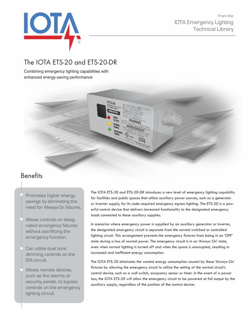
The IOTA ETS-20 and ETS-20-DR introduces a new level of emergency lighting capability for facilities and public spaces that utilize auxiliary power sources, such as a generator or inverter supply, for its code-required emergency egress lighting. The ETS-20 is a pow-erful control device that delivers increased functionality to the designated emergency loads connected to these auxiliary supplies.
In scenarios where emergency power is supplied by an auxiliary generator or inverter, the designated emergency circuit is separate from the normal switched or controlled lighting circuit. This arrangement prevents the emergency fixtures from being in an ‘OFF’ state during a loss of normal power. The emergency circuit is in an ‘Always On’ state, even when normal lighting is turned off and when the space is unoccupied, resulting in increased and inefficient energy consumption.
The IOTA ETS-20 eliminates the wasted energy consumption caused by these ‘Always-On’ fixtures by allowing the emergency circuit to utilize the setting of the normal circuit’s control device, such as a wall switch, occupancy sensor or timer. In the event of a power loss, the IOTA ETS-20 will allow the emergency circuit to be powered at full output by the auxiliary supply, regardless of the position of the control device.
From the
IOTA Emergency Lighting Technical Library
Promotes higher energy savings by eliminating the need for Always-On fixtures.
Allows controls on desig-nated emergency fixtures without sacrificing the emergency function.
Can utilize dual zone dimming controls on the EM circuit.
Allows remote devices, such as fire alarms or security panels, to bypass controls on the emergency lighting circuit.
How the IOTA ETS-20 Works
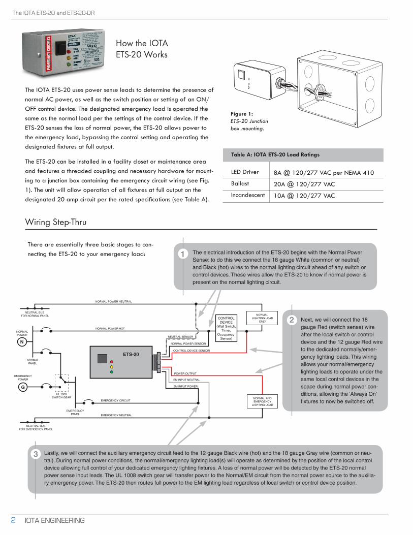
The IOTA ETS-20 uses power sense leads to determine the presence of normal AC power, as well as the switch position or setting of an ON/OFF control device. The designated emergency load is operated the same as the normal load per the settings of the control device. If the ETS-20 senses the loss of normal power, the ETS-20 allows power to the emergency load, bypassing the control setting and operating the designated fixtures at full output.
The ETS-20 can be installed in a facility closet or maintenance area and features a threaded coupling and necessary hardware for mount-ing to a junction box containing the emergency circuit wiring (see Fig. 1). The unit will allow operation of all fixtures at full output on the designated 20 amp circuit per the rated specifications (see Table A).
There are essentially three basic stages to con-necting the ETS-20 to your emergency load: The electrical introduction of the ETS-20 begins with the Normal Power
Sense: to do this we connect the 18 gauge White (common or neutral) and Black (hot) wires to the normal lighting circuit ahead of any switch or control devices. These wires allow the ETS-20 to know if normal power is present on the normal lighting circuit.
Next, we will connect the 18 gauge Red (switch sense) wire after the local switch or control device and the 12 gauge Red wire to the dedicated normally/emer-gency lighting loads. This wiring allows your normal/emergency lighting loads to operate under the same local control devices in the space during normal power con-ditions, allowing the ‘Always On’ fixtures to now be switched off.EMERGENCY CIRCUIT
EM INPUT POWER
NORMAL POWER HOT
NORMAL POWER NEUTRAL
EMERGENCY NEUTRAL
ETS-20
NORMAL ANDEMERGENCY
LIGHTING LOAD
EM INPUT NEUTRAL
POWER OUTPUT
CONTROL DEVICE SENSOR
NEUTRAL SENSOR
NORMAL POWER SENSOR
NORMAL LIGHTING LOAD
ONLYCONTROL
DEVICE(Wall Switch,
Timer,Occupancy
Sensor)
NEUTRAL BUS FOR NORMAL PANEL
NEUTRAL BUSFOR EMERGENCY PANEL
NORMALPOWER
EMERGENCYPOWER
NORMALPANEL
EMERGENCYPANEL
UL 1008SWITCH GEAR
N
G
Lastly, we will connect the auxiliary emergency circuit feed to the 12 gauge Black wire (hot) and the 18 gauge Gray wire (common or neu-tral). During normal power conditions, the normal/emergency lighting load(s) will operate as determined by the position of the local control device allowing full control of your dedicated emergency lighting fixtures. A loss of normal power will be detected by the ETS-20 normal power sense input leads. The UL 1008 switch gear will transfer power to the Normal/EM circuit from the normal power source to the auxilia-ry emergency power. The ETS-20 then routes full power to the EM lighting load regardless of local switch or control device position.
Wiring Step-Thru
1
2
3
The IOTA ETS-20 and ETS-20-DR
IOTA ENGINEERING2
Table A: IOTA ETS-20 Load Ratings
8A @ 120/277 VAC per NEMA 410
20A @ 120/277 VAC
10A @ 120/277 VAC
LED Driver
Ballast
Incandescent
Figure 1: ETS-20 Junction box mounting.
Additional Control Capabilities
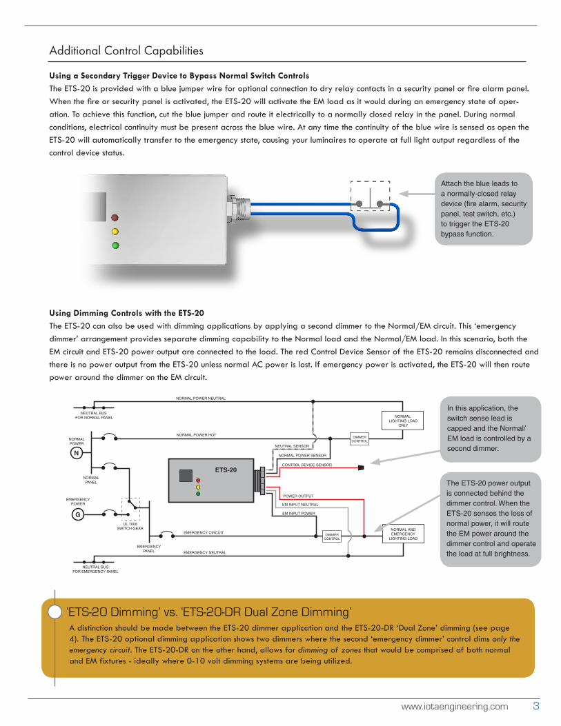
Using a Secondary Trigger Device to Bypass Normal Switch Controls The ETS-20 is provided with a blue jumper wire for optional connection to dry relay contacts in a security panel or fire alarm panel. When the fire or security panel is activated, the ETS-20 will activate the EM load as it would during an emergency state of oper-ation. To achieve this function, cut the blue jumper and route it electrically to a normally closed relay in the panel. During normal conditions, electrical continuity must be present across the blue wire. At any time the continuity of the blue wire is sensed as open the ETS-20 will automatically transfer to the emergency state, causing your luminaires to operate at full light output regardless of the control device status.
Using Dimming Controls with the ETS-20 The ETS-20 can also be used with dimming applications by applying a second dimmer to the Normal/EM circuit. This ‘emergency dimmer’ arrangement provides separate dimming capability to the Normal load and the Normal/EM load. In this scenario, both the EM circuit and ETS-20 power output are connected to the load. The red Control Device Sensor of the ETS-20 remains disconnected and there is no power output from the ETS-20 unless normal AC power is lost. If emergency power is activated, the ETS-20 will then route power around the dimmer on the EM circuit.
www.iotaengineering.com 3
Attach the blue leads to a normally-closed relay device (fire alarm, security panel, test switch, etc.) to trigger the ETS-20 bypass function.
EMERGENCY CIRCUIT
EM INPUT POWER
NORMAL POWER HOT
NORMAL POWER NEUTRAL
EMERGENCY NEUTRAL
ETS-20
NORMAL ANDEMERGENCY
LIGHTING LOAD
EM INPUT NEUTRAL
POWER OUTPUT
CONTROL DEVICE SENSOR
NEUTRAL SENSOR
NORMAL POWER SENSOR
NORMAL LIGHTING LOAD
ONLY
NEUTRAL BUS FOR NORMAL PANEL
NEUTRAL BUSFOR EMERGENCY PANEL
NORMALPOWER
EMERGENCYPOWER
NORMALPANEL
EMERGENCYPANEL
UL 1008SWITCH GEAR
N
G
DIMMERCONTROL
DIMMERCONTROL
‘ETS-20 Dimming’ vs. ‘ETS-20-DR Dual Zone Dimming’A distinction should be made between the ETS-20 dimmer application and the ETS-20-DR ‘Dual Zone’ dimming (see page 4). The ETS-20 optional dimming application shows two dimmers where the second ‘emergency dimmer’ control dims only the emergency circuit. The ETS-20-DR on the other hand, allows for dimming of zones that would be comprised of both normal and EM fixtures - ideally where 0-10 volt dimming systems are being utilized.
In this application, the switch sense lead is capped and the Normal/EM load is controlled by a second dimmer.
The ETS-20 power output is connected behind the dimmer control. When the ETS-20 senses the loss of normal power, it will route the EM power around the dimmer control and operate the load at full brightness.
P.O. BOX 11846 TUCSON, AZ 85734 • 1361 E. WIEDING ROAD TUCSON, AZ 85706 • 1-800-866-4682 • FAX (520) 741-2837 www.iotaengineering.com
Rev 030716 © 2016 IOTA Engineering, LLC. All Rights Reserved.
The IOTA ETS-20 and ETS-20-DR
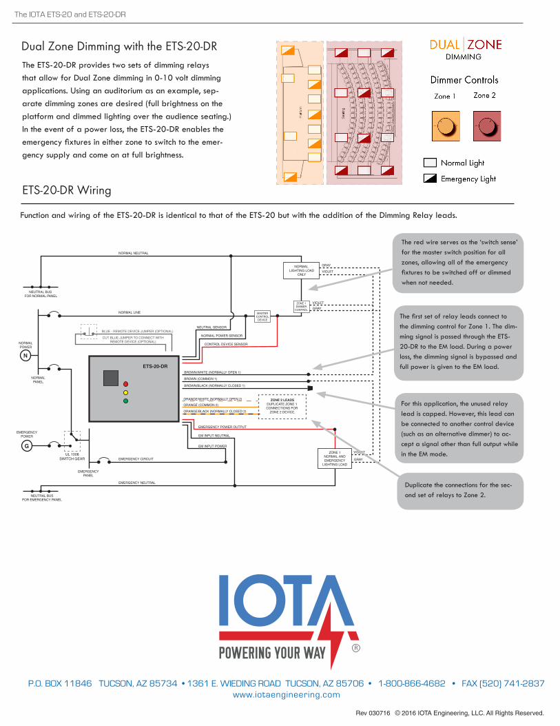
Dual Zone Dimming with the ETS-20-DRThe ETS-20-DR provides two sets of dimming relays that allow for Dual Zone dimming in 0-10 volt dimming applications. Using an auditorium as an example, sep-arate dimming zones are desired (full brightness on the platform and dimmed lighting over the audience seating.) In the event of a power loss, the ETS-20-DR enables the emergency fixtures in either zone to switch to the emer-gency supply and come on at full brightness.
EMERGENCY CIRCUIT
EM INPUT POWER
NORMAL LINE
NORMAL NEUTRAL
EMERGENCY NEUTRAL
ZONE 1NORMAL ANDEMERGENCY
LIGHTING LOAD
EM INPUT NEUTRAL
EMERGENCY POWER OUTPUT
BLUE - REMOTE DEVICE JUMPER (OPTIONAL)
CONTROL DEVICE SENSOR
NEUTRAL SENSOR
NORMAL POWER SENSOR
NORMAL LIGHTING LOAD
ONLY
CUT BLUE JUMPER TO CONNECT WITHREMOTE DEVICE (OPTIONAL)
NEUTRAL BUS FOR NORMAL PANEL
NEUTRAL BUSFOR EMERGENCY PANEL
NORMALPOWER
EMERGENCYPOWER
NORMALPANEL
EMERGENCYPANEL
UL 1008SWITCH GEAR
N
G
BROWN (COMMON 1)
BROWN/WHITE (NORMALLY OPEN 1)
BROWN/BLACK (NORMALLY CLOSED 1)
ORANGE (COMMON 2)
ORANGE/WHITE (NORMALLY OPEN 2)
ORANGE/BLACK (NORMALLY CLOSED 2)
ZONE 1DIMMER
CONTROL
VIOLET
GRAY
VIOLET
VIOLET
GRAY
GRAY
ZONE 2 LEADSDUPLICATE ZONE 1 CONNECTIONS FOR
ZONE 2 DEVICE.
ETS-20-DR
MASTERCONTROL
DEVICE
ETS-20-DR Wiring
Function and wiring of the ETS-20-DR is identical to that of the ETS-20 but with the addition of the Dimming Relay leads.
The first set of relay leads connect to the dimming control for Zone 1. The dim-ming signal is passed through the ETS-20-DR to the EM load. During a power loss, the dimming signal is bypassed and full power is given to the EM load.
Duplicate the connections for the sec-ond set of relays to Zone 2.
The red wire serves as the ‘switch sense’ for the master switch position for all zones, allowing all of the emergency fixtures to be switched off or dimmed when not needed.
For this application, the unused relay lead is capped. However, this lead can be connected to another control device (such as an alternative dimmer) to ac-cept a signal other than full output while in the EM mode.