The Investigation of Equivalent Harmonic Impedances of VSC ... · The Investigation of Equivalent...
5
The Investigation of Equivalent Harmonic Impedances of VSC-Based HVDC Systems Phuchuy Nguyen and Minxiao Han School of Electrical Engineering, North China Electric Power University, Beijing 102206, P.R. China Email: [email protected], [email protected] Abstract—In a PWM-based low level voltage source converter (VSC), the harmonic level is significant that filters should be required on the both sides of the converter. The converter will have harmonic impedances as seen from the both sides, and it matters to assess these impedances to calculate their impact on filters and the network also. In this paper, the equivalent harmonic impedances on both ac- and dc-sides of VSC are calculated based on the ac/dc harmonic interaction with any switching components. The effect of cross-interaction between switching components on the harmonic impedance is also investigated. Moreover, the resonance analysis is performed on the both ac-side and dc- side of a VSC-based HVDC system. Although the VSC dc- side harmonic impedance is very large, the resonances may occur due to the existence of dc capacitors and dc cables. On the ac-side, the resonances may occur at the output terminal of the converter and interact with the dc-side circuit, causing harmonic amplification. Index Terms—VSC, VSC-based HVDC, resonance, harmonic impedance I. INTRODUCTION The introduction of Voltage-Sourced Converter (VSC)-based HVDC to power system offers the potential to improve control of power flow and enhance system stability. However, VSC-based HVDC producing harmonics on the both ac-side and dc-side is inherent by the VSC itself, and will interact with harmonic distortions already existed in the system. The harmonics of VSC are directly associated with the type of VSC technologies, modulation techniques and the switching frequency [1]. Harmonics are transferred between the two sides of the VSC and may interact with the ac system leading to disadvantage effects. A practical case in [2] shows that harmonic instability may occur if there is an unbalanced second harmonic generated by a nearby saturated transformer on the ac-side of VSC. Based on analyzing basic current and voltage equations of (Current Source Converter) CSC and VSC, the authors in [3] establish simple rules of harmonic transfer through converters by using switching functions represented in space vector form. For resonance and filter studies, the converter’s harmonic impedances are important. The ac- and dc-side impedances of conventional line-commutated HVDC converters were calculated by applying the harmonic Manuscript received October 20, 2014; revised April 21, 2015. transfer rules [4]. In the case of VSC, the dc equivalent impedance of VSC is formulated in [5] for analyzing non- integral harmonic resonance from the interaction of AC/DC systems. The ac equivalent impedance of VSC is formulated in [6] also based on the harmonic transfer through VSC. However, all the authors just investigated the interaction of the fundamental switching component only. Harmonic transfer rules of VSC are valid for both voltage harmonics and current harmonics. Based on the rules, this paper formulated the ac- and dc-side harmonic impedances of the VSC by using the switching functions represented in space vector form. The harmonic impedances derived with considering not only the fundamental switching component, but also the high frequency switching ones of the VSC’s switching functions. The influences of switching components on these harmonic impedances are dominant if the sequence of interacted harmonic is the same to the sequence of the switching components. Moreover, the cross-interaction between switching components was also investigated. Consequently, the dc- and ac-side equivalent harmonic impedances of the VSC in VSC-based HVDC systems were used in the ac- and dc-side to plot driving point impedance curves, giving a clearer view of the harmonic resonance analysis. II. VSC AC- AND DC-SIDE HARMONIC IMPEDANCES Harmonic impedance of the VSC responds the relation between voltage and current at different frequencies. For simplicity, assuming that the VSC analyzed in this case is symmetric. In the time domain, the relation between these two quantities can be expressed as (1) [7]. * /2 3 Re 4 V d d V u t Kt u t i t Kt i t (1) where , V V u t i t : Space vector of ac-side voltage and current. , d d u t i t : DC-Side voltage and current. Kt : The space vector of three sinusoidal switching functions. The switching function comprises the fundamental frequency component called frequency switching component, and high-frequency ones called high-order International Journal of Electronics and Electrical Engineering Vol. 4, No. 1, February 2016 ©2016 Int. J. Electron. Electr. Eng. 29 doi: 10.18178/ijeee.4.1.29-33
-
Upload
hoangquynh -
Category
Documents
-
view
219 -
download
1
Transcript of The Investigation of Equivalent Harmonic Impedances of VSC ... · The Investigation of Equivalent...

The Investigation of Equivalent Harmonic
Impedances of VSC-Based HVDC Systems
Phuchuy Nguyen and Minxiao Han School of Electrical Engineering, North China Electric Power University, Beijing 102206, P.R. China
Email: [email protected], [email protected]
Abstract—In a PWM-based low level voltage source
converter (VSC), the harmonic level is significant that filters
should be required on the both sides of the converter. The
converter will have harmonic impedances as seen from the
both sides, and it matters to assess these impedances to
calculate their impact on filters and the network also. In this
paper, the equivalent harmonic impedances on both ac- and
dc-sides of VSC are calculated based on the ac/dc harmonic
interaction with any switching components. The effect of
cross-interaction between switching components on the
harmonic impedance is also investigated. Moreover, the
resonance analysis is performed on the both ac-side and dc-
side of a VSC-based HVDC system. Although the VSC dc-
side harmonic impedance is very large, the resonances may
occur due to the existence of dc capacitors and dc cables. On
the ac-side, the resonances may occur at the output terminal
of the converter and interact with the dc-side circuit,
causing harmonic amplification.
Index Terms—VSC, VSC-based HVDC, resonance,
harmonic impedance
I. INTRODUCTION
The introduction of Voltage-Sourced Converter
(VSC)-based HVDC to power system offers the potential
to improve control of power flow and enhance system
stability. However, VSC-based HVDC producing
harmonics on the both ac-side and dc-side is inherent by
the VSC itself, and will interact with harmonic distortions
already existed in the system. The harmonics of VSC are
directly associated with the type of VSC technologies,
modulation techniques and the switching frequency [1].
Harmonics are transferred between the two sides of the
VSC and may interact with the ac system leading to
disadvantage effects. A practical case in [2] shows that
harmonic instability may occur if there is an unbalanced
second harmonic generated by a nearby saturated
transformer on the ac-side of VSC. Based on analyzing
basic current and voltage equations of (Current Source
Converter) CSC and VSC, the authors in [3] establish
simple rules of harmonic transfer through converters by
using switching functions represented in space vector
form. For resonance and filter studies, the converter’s
harmonic impedances are important. The ac- and dc-side
impedances of conventional line-commutated HVDC
converters were calculated by applying the harmonic
Manuscript received October 20, 2014; revised April 21, 2015.
transfer rules [4]. In the case of VSC, the dc equivalent
impedance of VSC is formulated in [5] for analyzing non-
integral harmonic resonance from the interaction of
AC/DC systems. The ac equivalent impedance of VSC is
formulated in [6] also based on the harmonic transfer
through VSC. However, all the authors just investigated
the interaction of the fundamental switching component
only.
Harmonic transfer rules of VSC are valid for both
voltage harmonics and current harmonics. Based on the
rules, this paper formulated the ac- and dc-side harmonic
impedances of the VSC by using the switching functions
represented in space vector form. The harmonic
impedances derived with considering not only the
fundamental switching component, but also the high
frequency switching ones of the VSC’s switching
functions. The influences of switching components on
these harmonic impedances are dominant if the sequence
of interacted harmonic is the same to the sequence of the
switching components. Moreover, the cross-interaction
between switching components was also investigated.
Consequently, the dc- and ac-side equivalent harmonic
impedances of the VSC in VSC-based HVDC systems
were used in the ac- and dc-side to plot driving point
impedance curves, giving a clearer view of the harmonic
resonance analysis.
II. VSC AC- AND DC-SIDE HARMONIC IMPEDANCES
Harmonic impedance of the VSC responds the relation
between voltage and current at different frequencies. For
simplicity, assuming that the VSC analyzed in this case is
symmetric. In the time domain, the relation between these
two quantities can be expressed as (1) [7].
*
/ 2
3Re
4
V d
d V
u t K t u t
i t K t i t (1)
where
, V Vu t i t : Space vector of ac-side voltage and
current.
, d du t i t : DC-Side voltage and current.
K t : The space vector of three sinusoidal switching
functions.
The switching function comprises the fundamental
frequency component called frequency switching
component, and high-frequency ones called high-order
International Journal of Electronics and Electrical Engineering Vol. 4, No. 1, February 2016
©2016 Int. J. Electron. Electr. Eng. 29doi: 10.18178/ijeee.4.1.29-33
switching components. The harmonic interaction rules
between two sides of the VSC with the fundamental
switching component were introduced in [7]. For
individual Nth
switching component, the space vector can
be expressed as:
ˆ Nj t
NK t K e
(2)
Generally, a background harmonic of on the ac-side
will produce only harmonic of N
on the dc-side;
while a background harmonic of on the dc-side will
transfer to the ac-side and induce two harmonic of
N and
N . The effect of these additional
harmonics should be taken into account in the calculation
process of equivalent harmonic impedances.
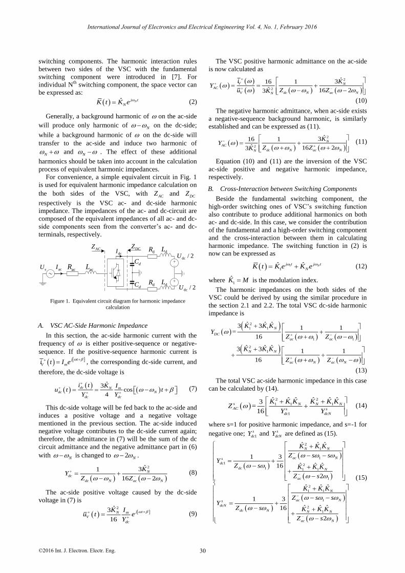
For convenience, a simple equivalent circuit in Fig. 1
is used for equivalent harmonic impedance calculation on
the both sides of the VSC, with ACZ and
DCZ
respectively is the VSC ac- and dc-side harmonic
impedance. The impedances of the ac- and dc-circuit are
composed of the equivalent impedances of all ac- and dc-
side components seen from the converter’s ac- and dc-
terminals, respectively.
dcI
dCsU
~acR
ACZ DCZ
+-
+-
dc / 2U
acI
dc / 2U
acL
dLdR
dLdR
dC
Figure 1. Equivalent circuit diagram for harmonic impedance calculation
A. VSC AC-Side Harmonic Impedance
In this section, the ac-side harmonic current with the
frequency of is either positive-sequence or negative-
sequence. If the positive-sequence harmonic current is
j t
V mi t I e , the corresponding dc-side current, and
therefore, the dc-side voltage is
ˆ3
cos4
dc N m
dc N
dc dc
i t K Iu t t
Y Y
(7)
This dc-side voltage will be fed back to the ac-side and
induces a positive voltage and a negative voltage
mentioned in the previous section. The ac-side induced
negative voltage contributes to the dc-side current again;
therefore, the admittance in (7) will be the sum of the dc
circuit admittance and the negative admittance part in (6)
with N is changed to 2 N .
2ˆ31
16 2
N
dc
dc N ac N
KY
Z Z (8)
The ac-side positive voltage caused by the dc-side
voltage in (7) is
2ˆ3
16
j tN m
V
dc
K Iu t e
Y
(9)
The VSC positive harmonic admittance on the ac-side
is now calculated as
2
2
ˆ316 1
ˆ 16 23
V N
AC
dc NV ac NN
i KY
Zu ZK
(10)
The negative harmonic admittance, when ac-side exists
a negative-sequence background harmonic, is similarly
established and can be expressed as (11).
2
2
ˆ316 1
ˆ 16 23
N
AC
dc N ac NN
KY
Z ZK
(11)
Equation (10) and (11) are the inversion of the VSC
ac-side positive and negative harmonic impedance,
respectively.
B. Cross-Interaction between Switching Components
Beside the fundamental switching component, the
high-order switching ones of VSC’s switching function
also contribute to produce additional harmonics on both
ac- and dc-side. In this case, we consider the contribution
of the fundamental and a high-order switching component
and the cross-interaction between them in calculating
harmonic impedance. The switching function in (2) is
now can be expressed as
1
1ˆ ˆ Nj tj t
NK t K e K e
(12)
where 1
ˆ K M is the modulation index.
The harmonic impedances on the both sides of the
VSC could be derived by using the similar procedure in
the section 2.1 and 2.2. The total VSC dc-side harmonic
impedance is
2
1 1
1 1
2
1
ˆ ˆ ˆ3 3 1 1=
16
ˆ ˆ ˆ3 3 1 1
16
N
DC
ac ac
N N
ac N ac N
K K KY
Z Z
K K K
Z Z
(13)
The total VSC ac-side harmonic impedance in this case
can be calculated by (14).
2 2
1 1 1
1
ˆ ˆ ˆ ˆ ˆ ˆ3=
16
s N N N
AC s s
dc dcN
K K K K K KZ
Y Y
(14)
where s=1 for positive harmonic impedance, and s=-1 for
negative one; 1
s
dcY and s
dcNY are defined as (15).
2
1
1
1 21 1 1
1
2
1 1
1
2
1
ˆ ˆ ˆ
1 3
ˆ ˆ ˆ16
2
ˆ ˆ ˆ
1 3
ˆ ˆ ˆ16
2
N N
ac Ns
dc
dc N
ac
N
ac Ns
dcN
dc N N N
ac N
K K K
Z s sY
Z s K K K
Z s
K K K
Z s sY
Z s K K K
Z s
(15)
International Journal of Electronics and Electrical Engineering Vol. 4, No. 1, February 2016
©2016 Int. J. Electron. Electr. Eng. 30

0 5 10 15 20 25 30 35 400
1,000
2,000
Mag
. (
)
Harmonic order
0 5 10 15 20 25 30 35 400
2000
4000
Mag.
( )
K1 and KPoS
K1 and KNeG
Figure 2. DC-side harmonic impedance with cross-interaction
0 5 10 15 20 25 30 35 40 45 500
0.2
0.4
0.6
0.8
1
1.2
1.4
Mag
. (
)
Harmonic order
0 5 10 15 20 25 30 35 40 45 500
0.2
0.4
0.6
0.8
1
1.2
1.4
Mag
. (
)
K1 and KPoS
K1 and KNeG
Figure 3. AC-side harmonic impedance with cross-interaction
Fig. 2 and Fig. 3 show the harmonic impedance
characteristics of the circuit in Fig. 1 with parameters as:
Rac = 1Ω, Lac=11.7mH, Cd =500 F, Rd = 2Ω, Ld = 5mH;
VSC: Modulation index M = 0.8, switching frequency fc
= 1050Hz.
Fig. 2 illustrates the VSC dc-side harmonic impedance
characteristic in considering the cross-interaction between
the fundamental switching component (K1) and high-
order positive (KPoS) and negative (KNeG) switching
components. Clearly, the parallel resonance points tend to
appear at the frequency lower than the frequency of KPoS
and higher than the frequency of the KNeG.
Fig. 3 illustrates the VSC ac-side harmonic impedance
under the cross-interaction between K1 and KPoS, and
between K1 and KNeG, for both cases of positive and
negative sequence background harmonic, respectively.
The harmonic impedance characteristics have small
changes with two parallel resonance points closed to the
switching frequency.
III. RESONANCE ANALYSIS OF VSC-BASED HVDC
SYSTEM
A. VSC-Based HVDC System Model
The VSC-based HVDC system is a point-to-point
scheme which consists of two VSC stations
interconnected by ±300kV dc cables and transfers power
of 600MW from 330kV ac system (Iscmax1 = 50kA) to
230kV ac system (Iscmax2 = 40kA). Fig. 4 represents the
main components of one half of the system with filters
are installed on the both sides of the converter station.
The equivalent impedance circuit is shown in Fig. 5.
In Fig. 5(a), 1ACZ is the VSC1 ac-side harmonic
impedance; 1SZ , 1TZ , 1RZ and 1FZ are equivalent
impedances of ac system 1, converter transformer,
converter reactor and filter respectively; PCC1 is the
Point of Common Connection and A1 is the VSC1’s
output terminal. In Fig. 5(b), 1DCZ and
2DCZ are
respectively the VSC1 and VSC2 dc-side harmonic
impedances; DC-link equivalent circuit includes dc
smoothing reactors (1LZ ,
2LZ ), dc-filters and dc
capacitors (1CFZ ,
2CFZ ), and the dc-cables. The dc-cables
are modeled as PI model, and their shunt capacitances are
at the proportional rate along the cable length that
exploited to reduce the size of the dc capacitors [8]. The
parameters of components are: dc capacitors Cd = 30F;
dc-cables: Rc = 13.9mΩ/km, Lc=0.159mH/km, Cc
=0.231F/km, Lcab = 850km; reactor XR=0.15p.u.
AC filter
Cable
Cable
Transformer Reactor
Cd
Cd
CF/2
RF LF
CF/2IGBT-VSC
Rd,Ld
Rd,Ld
Idc
A
AC system
Figure 4. Schematic diagram of one half of the studied VSC-HVDC
system
S1
Z
R1Z T1Z
F1
Z
AC
1Z
PCC1A1
(a) The ac-side circuit
2C
FZ
DC
2ZC
F1
Z
DC1L1Z L2ZseriesZ
shunt
Y
shunt
Y
DC
1Z
DC2
(b) The dc-side circuit
Figure 5. Impedance model for resonance analysis of the VSC-based HVDC system
International Journal of Electronics and Electrical Engineering Vol. 4, No. 1, February 2016
©2016 Int. J. Electron. Electr. Eng. 31

0 2 4 6 8 10 12 140
100
200
300
Mag
. (
)
Harmonic order (a) PCC: PoS B.G Harmonic
0 2 4 6 8 10 12 140
1
2
Mag.
( )
Harmonic order (b) PPC: NeG B.G Harmonic
0 2 4 6 8 10 12 140
5
10
15
20
Harmonic order(c) VSC terminal
Mag
. (
)
PoS B.G. Harmonic
NeG B.G. Harmonic
Figure 6. Driving point impedance seen from different points of the ac-side circuit
1 2 4 6 8 10 12 140
50
100
150
Mag
. (
)
Harmonic order
DC1
DC2
Figure 7. DC-Side driving point impedance seen from VSC1 (blue) and VSC2 (red) dc-terminals
B. Result Analysis
Fig. 6 shows the driving point impedance as seen from
the Point of Common Coupling (PCC) and the VSC’s
output terminal (A point) in both cases of PoS and NeG
background harmonics. At the PCC point (Fig. 6(a) and
Fig. 6(b)), there exists only one resonant point close to
the tenth harmonic in the both cases, but the magnitudes
are different. At the ac terminal of the VSC (Fig. 6(c)), a
series and resonance points appear with parallel
resonances at the NeG 3rd
harmonic and PoS 5th
harmonic.
Fig. 7 shows the driving point impedances seen from
the dc terminal of VSC1 (DC1), and the dc terminal of
VSC2 (DC2) referred to the DC1 point. The impedance-
frequency responding curves have no change in shape
with parallel resonant points appear at the 4th
harmonics,
and close to the 5th
and 6th
harmonics. Because of the 3rd
harmonic filter, the circuit has a series resonance at the
3rd
harmonic.
In Fig. 7, the 4th
harmonic voltage at the dc terminal of
VSC1 will increase largely with a small 4th
harmonic
current injected in. This 4th
harmonic transferred to the
ac-side and causing parallel resonance points with the
PoS 5th
harmonic and NeG 3rd
harmonic (see Fig. 6(c)),
this is called composite resonance between ac- and dc-
side, so that the feedback to the dc-side is insignificant. It
should be noted that for a VSC, the feed back from the
dc-side to the ac-side is significant with parallel
resonances on the dc-side; however, the feed back from
the ac-side to the dc-side is significant with a series
resonances.
IV. CONCLUSION
The harmonic impedances on the both sides of VSC
were calculated based on the switching technique and
harmonic interaction characteristic of the converter. With
different switching components, the contributions on
harmonic impedance calculation are different. The
fundamental switching component is the largest and
therefore, contributes the most to equivalent harmonic
impedances in both cases of positive and negative
sequence background harmonics. For the high frequency
switching components, they contribute dominantly in
cross-interaction with the fundamental one if they have
same sequences with the background harmonics.
The VSC ac- and dc-side harmonic impedances are
beneficial to resonance analysis and filter designs in the
VSC-based HVDC system. The impedance-frequency
responses give a visual view at which frequency
resonance points appear, which gives the aid of proposing
effective relevant mitigation methods, minimizing the site
measurements in harmonic investigations.
ACKNOWLEDGMENT
This work was supported by State Grid Cooperation of
China, Major Projects on Planning and Operation Control
of Large Scale Grid SGCC-MPLG019-2012, National
Science Foundation of China: 51177044.
REFERENCES
[1] N. Flourentzou, V. G. Agelidis, and G. D. Demetriades, “VSC-
Based HVDC power transmission systems: An overview,” IEEE
Transactions on Power Electronics, vol. 24, pp. 592-602, 2009.
[2] A. E. Hammad, “Analysis of second harmonic instability for the
Chateauguay HVDC/VSC scheme,” IEEE Trans. Power Delivery
vol. 7, NO. 1, pp. 410-415, Jan. 1992.
[3] J. Ying and A. Ekstrom, “General analysis of harmonic transfer
through converters,” IEEE Transactions on Power Electronics, vol.
12, pp. 287-293, 1997.
International Journal of Electronics and Electrical Engineering Vol. 4, No. 1, February 2016
©2016 Int. J. Electron. Electr. Eng. 32

[4] P. Riedel, “Harmonic voltage and current transfer, and AC- and DC-side impedances of HVDC converters,” IEEE Transactions on
Power Delivery, vol. 20, pp. 2095-2099, 2005.
[5] L. Tang and O. Boon-Teck, “Converter nonintegral harmonics from AC network resonating with DC network,” in Proc. IEEE
36th Industrial Application Society Annual Conference, 2001, vol. 4, pp. 2186-2192.
[6] G. Yang, VSC-Based HVDC Transmission System Technology (in
Chinese), Beijing, China: China Electric Power Press, 2009, pp. 172-177.
[7] P. Nguyen and M. Han, “Study on harmonic propagation of VSC-based HVDC systems,” in Proc. PowerCon 2014, Chengdu, China,
2014.
[8] C. Chang Hsin and R. Bucknall, “Analysis of harmonics in Subsea power transmission cables used in VSC-HVDC transmission
systems operating under steady-state conditions,” IEEE Transactions on Power Delivery, vol. 22, pp. 2489-2497, 2007.
Phuchuy Nguyen received his B.Sc and M.Sc
degree from Hanoi University of Science and
Technology (HUST), Viet Nam in 2003 and
2010 respectively. Now he is a Ph.D. student in
the Electric Power System and Its Automation
at North China Electric Power University
(NCEPU), Beijing, China. The main research
interest is in the field of flexible HVDC
transmission systems and power quality.
Minxiao Han was born in Shannxi, China, in 1963. He received his
B.Sc. from Xi’an Jiaotong University in 1984, M.Sc. and Ph.D. from
North China Electric Power University (NCEPU) in 1987 and 1995 respectively. He was a visiting research fellow in Queen’s University of
Belfast, U.K. and post-doctoral research fellow with Kobe University, Japan. He is active in professional society activities and international
cooperation relating with the field of application of power electronics in
power system including HVDC & FACTS, power quality and the integration of renewable generation in power network.
International Journal of Electronics and Electrical Engineering Vol. 4, No. 1, February 2016
©2016 Int. J. Electron. Electr. Eng. 33