The influence of the bulk liquid thermal boundary layer on...
13
The influence of the bulk liquid thermal boundary layer on saturated nucleate boiling Jun Liao, Renwei Mei * , James F. Klausner Department of Mechanical and Aerospace Engineering, University of Florida, 231 Aerospace Building, P.O. Box 116250, Gainesville, FL 32611-6250, USA Abstract A physical model for vapor bubble growth in saturated nucleate boiling has been developed that includes both heat transfer through the liquid microlayer and that from the bulk superheated liquid surrounding the bubble. Both asymptotic and numerical solutions for the liquid temperature field surrounding a hemispherical bubble reveal the existence of a thin unsteady thermal boundary layer adjacent to the bubble dome. During the early stages of bubble growth, heat transfer to the bubble dome through the unsteady thermal boundary layer constitutes a substantial contribution to vapor bubble growth. The model is used to elucidate recent experimental observations of bubble growth and heat transfer on constant temperature microheaters reported by Yad- danapudi and Kim [Multiphase Sci. Technol. 12(3–4) (2001) 47] and confirms that the heat transfer through the bubble dome can be a significant portion of the overall energy supply for the bubble growth. Ó 2003 Elsevier Inc. All rights reserved. Keywords: Heat transfer; Nucleate boiling; Bubble growth 1. Introduction During the past 40 years, the microlayer model has been widely accepted and used to explain bubble growth and the associated heat transfer in heterogeneous nucleate boiling. The microlayer concept was introduced by Moore and Mesler (1961), Labunstov (1963) and Cooper (1969). The microlayer is a thin liquid layer that resides beneath a growing vapor bubble. Because the layer is quite thin, the temperature gradient and the corresponding heat flux across the microlayer are high. The vapor generated by strong evaporation through the liquid microlayer substantially supports the bubble growth. Popular opinion concerning the microlayer model is that the majority of evaporation takes place at the mi- crolayer. A number of bubble growth models using microlayer theory have been proposed based on this assumption such as van Stralen et al. (1975a,b), Cooper and Vijuk (1970), and Fyodorov and Klimenko (1989). These models were partially successful in predicting the bubble growth under limited conditions but are not applicable to a wide range of conditions. Lee and Nydahl (1989) used a finite difference method to study bubble growth and heat transfer in the microlayer. However their model assumes a constant wall temper- ature, which is not valid for heat flux controlled boiling since the rapidly growing bubble draws a substantial amount of heat from the wall through the microlayer, which reduces the local wall temperature. Mei et al. (1995a,b) considered the simultaneous energy transfer among the vapor bubble, liquid microlayer, and solid heater in modeling bubble growth. For simplicity, the bulk liquid outside the microlayer was assumed to be at the saturation temperature so that the vapor dome is at thermal equilibrium with the surrounding bulk liquid. The temperature in the heater was determined by solv- ing the unsteady heat conduction equation. The pre- dicted bubble growth rates agreed very well with those measured over a wide range of experimental conditions that were reported by numerous investigators. Empirical constants to account for the bubble shape and micro- layer angle were introduced. Recently, Yaddanapudi and Kim (2001) experimen- tally studied single bubbles growing on a constant * Corresponding author. Tel.: +1-352-392-0888; fax: +1-352-392- 7303. E-mail address: [email protected]fl.edu (R. Mei)., 0142-727X/$ - see front matter Ó 2003 Elsevier Inc. All rights reserved. doi:10.1016/j.ijheatfluidflow.2003.11.012 International Journal of Heat and Fluid Flow 25 (2004) 196–208 www.elsevier.com/locate/ijhff
Transcript of The influence of the bulk liquid thermal boundary layer on...

International Journal of Heat and Fluid Flow 25 (2004) 196–208
www.elsevier.com/locate/ijhff
The influence of the bulk liquid thermal boundary layeron saturated nucleate boiling
Jun Liao, Renwei Mei *, James F. Klausner
Department of Mechanical and Aerospace Engineering, University of Florida, 231 Aerospace Building, P.O. Box 116250,
Gainesville, FL 32611-6250, USA
Abstract
A physical model for vapor bubble growth in saturated nucleate boiling has been developed that includes both heat transfer
through the liquid microlayer and that from the bulk superheated liquid surrounding the bubble. Both asymptotic and numerical
solutions for the liquid temperature field surrounding a hemispherical bubble reveal the existence of a thin unsteady thermal
boundary layer adjacent to the bubble dome. During the early stages of bubble growth, heat transfer to the bubble dome through
the unsteady thermal boundary layer constitutes a substantial contribution to vapor bubble growth. The model is used to elucidate
recent experimental observations of bubble growth and heat transfer on constant temperature microheaters reported by Yad-
danapudi and Kim [Multiphase Sci. Technol. 12(3–4) (2001) 47] and confirms that the heat transfer through the bubble dome can
be a significant portion of the overall energy supply for the bubble growth.
� 2003 Elsevier Inc. All rights reserved.
Keywords: Heat transfer; Nucleate boiling; Bubble growth
1. Introduction
During the past 40 years, the microlayer model has
been widely accepted and used to explain bubble growth
and the associated heat transfer in heterogeneous
nucleate boiling. The microlayer concept was introduced
by Moore and Mesler (1961), Labunstov (1963) and
Cooper (1969). The microlayer is a thin liquid layer thatresides beneath a growing vapor bubble. Because the
layer is quite thin, the temperature gradient and the
corresponding heat flux across the microlayer are high.
The vapor generated by strong evaporation through the
liquid microlayer substantially supports the bubble
growth.
Popular opinion concerning the microlayer model is
that the majority of evaporation takes place at the mi-crolayer. A number of bubble growth models using
microlayer theory have been proposed based on this
assumption such as van Stralen et al. (1975a,b), Cooper
and Vijuk (1970), and Fyodorov and Klimenko (1989).
* Corresponding author. Tel.: +1-352-392-0888; fax: +1-352-392-
7303.
E-mail address: [email protected] (R. Mei).,
0142-727X/$ - see front matter � 2003 Elsevier Inc. All rights reserved.
doi:10.1016/j.ijheatfluidflow.2003.11.012
These models were partially successful in predicting the
bubble growth under limited conditions but are not
applicable to a wide range of conditions. Lee and
Nydahl (1989) used a finite difference method to study
bubble growth and heat transfer in the microlayer.
However their model assumes a constant wall temper-
ature, which is not valid for heat flux controlled boiling
since the rapidly growing bubble draws a substantialamount of heat from the wall through the microlayer,
which reduces the local wall temperature. Mei et al.
(1995a,b) considered the simultaneous energy transfer
among the vapor bubble, liquid microlayer, and solid
heater in modeling bubble growth. For simplicity, the
bulk liquid outside the microlayer was assumed to be at
the saturation temperature so that the vapor dome is at
thermal equilibrium with the surrounding bulk liquid.The temperature in the heater was determined by solv-
ing the unsteady heat conduction equation. The pre-
dicted bubble growth rates agreed very well with those
measured over a wide range of experimental conditions
that were reported by numerous investigators. Empirical
constants to account for the bubble shape and micro-
layer angle were introduced.
Recently, Yaddanapudi and Kim (2001) experimen-tally studied single bubbles growing on a constant

Nomenclature
A dimensionless parameter for bubble growth
Ab area of vapor bubble dome exposed to bulk
liquid
Am area of wedge shaped interface
c ratio of wedge shaped interface radius and
vapor bubble radius
c1 microlayer wedge angle parameter; empiri-
cally determinedd bubble diameter
deq equivalent bubble diameter
hfg latent heat of vaporization
k thermal conductivity
L local microlayer thickness
n normal direction
R vapor bubble radius_R bubble growth rateR0, w and u spherical coordinates
R0
dimensionless radial coordinate
Rb radius of wedge shaped interface
R0 initial bubble radius
r radial coordinate
SR0 and Sw stretching factor in computation
T temperature
Tsat saturated temperatureTw initial solid temperature
Tb bulk liquid temperature
t time
tc characteristic time
tw waiting period
t0 initial time
Vb vapor bubble volume
X boundary layer coordinate
Z coordinate in the direction normal to the
heating surface
Greeks
a thermal diffusivity
DTsat solid heater superheatd superheated bulk liquid thermal boundary
layer thickness
d� dimensionless thickness of unsteady thermal
boundary layer
U velocity potential function for liquid flow
/ microlayer wedge angle
g and n computational coordinates
m kinematic viscosityh dimensionless temperature of liquid
h0 initial dimensionless temperature of liquid
q density
r stretched time in computation
s dimensionless time
Superscripts
in inner solution
out outer solution
Subscripts
b bubblel liquid
ml microlayer
v vapor
1 far field condition
J. Liao et al. / Int. J. Heat and Fluid Flow 25 (2004) 196–208 197
temperature heater. The heater temperature was kept
constant by using electronic feed back loops, and the
power required to maintain the temperature was mea-
sured throughout the bubble growth period. Their re-
sults show that during the bubble growth period, the
heat flux from the wall through the microlayer is only
about 54% of the total heat required to sustain the
measured growth rate. It poses a new challenge to themicrolayer theory since a substantial portion of the en-
ergy transferred to the bubble cannot be accounted for.
Since a growing vapor bubble consists of a thin liquid
microlayer, which is in contact with the solid heater, and
a vapor dome, which is in contact with the bulk liquid,
the experimental observations of Yaddanapudi and Kim
(2001) leads us to postulate that the heat transfer
through the bubble dome may play an important role inthe bubble growth process, even for saturated boiling.
Because the wall is superheated, a thermal boundary
layer exists between the background saturated bulk li-
quid and the wall; within this thermal boundary layer
the liquid temperature is superheated. During the initial
stage of the bubble growth, because the bubble is very
small in size, it is completely immersed within this
superheated bulk liquid thermal boundary layer. As the
vapor bubble grows rapidly, a new unsteady thermal
boundary layer develops between the saturated vapor
dome and the surrounding superheated liquid. The
thickness of the new unsteady thermal boundary layershould be inversely related to the bubble growth rate;
see the asymptotic analysis that follows. Hence the ini-
tial rapid growth of the bubble, which results in a thin
unsteady thermal boundary layer, is accompanied by a
substantial amount of heat transfer from the sur-
rounding superheated liquid to the bubble through the
vapor bubble dome. This is an entirely different heat
transfer mechanism than that associated with conven-tional microlayer theory.
In fact, many previous bubble growth models have
attempted to include the evaporation through the bub-
ble dome, such as Han and Griffith (1965) and van
R(t)
Solid wall;heat issupplied fromwithin or below
Backgroundbulk liquid
Bulk liquidthermal boundary
layer
Liquidmicrolayer
z
Ψ
φ
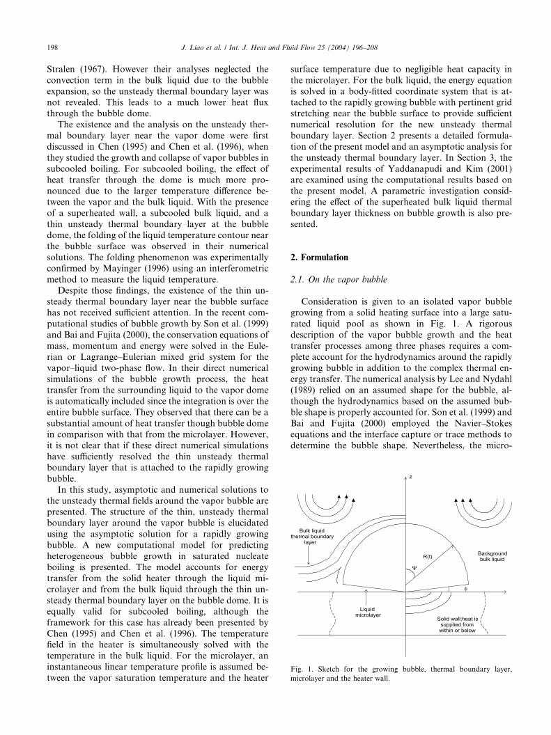
Fig. 1. Sketch for the growing bubble, thermal boundary layer,
microlayer and the heater wall.
198 J. Liao et al. / Int. J. Heat and Fluid Flow 25 (2004) 196–208
Stralen (1967). However their analyses neglected the
convection term in the bulk liquid due to the bubble
expansion, so the unsteady thermal boundary layer was
not revealed. This leads to a much lower heat fluxthrough the bubble dome.
The existence and the analysis on the unsteady ther-
mal boundary layer near the vapor dome were first
discussed in Chen (1995) and Chen et al. (1996), when
they studied the growth and collapse of vapor bubbles in
subcooled boiling. For subcooled boiling, the effect of
heat transfer through the dome is much more pro-
nounced due to the larger temperature difference be-tween the vapor and the bulk liquid. With the presence
of a superheated wall, a subcooled bulk liquid, and a
thin unsteady thermal boundary layer at the bubble
dome, the folding of the liquid temperature contour near
the bubble surface was observed in their numerical
solutions. The folding phenomenon was experimentally
confirmed by Mayinger (1996) using an interferometric
method to measure the liquid temperature.Despite those findings, the existence of the thin un-
steady thermal boundary layer near the bubble surface
has not received sufficient attention. In the recent com-
putational studies of bubble growth by Son et al. (1999)
and Bai and Fujita (2000), the conservation equations of
mass, momentum and energy were solved in the Eule-
rian or Lagrange–Eulerian mixed grid system for the
vapor–liquid two-phase flow. In their direct numericalsimulations of the bubble growth process, the heat
transfer from the surrounding liquid to the vapor dome
is automatically included since the integration is over the
entire bubble surface. They observed that there can be a
substantial amount of heat transfer though bubble dome
in comparison with that from the microlayer. However,
it is not clear that if these direct numerical simulations
have sufficiently resolved the thin unsteady thermalboundary layer that is attached to the rapidly growing
bubble.
In this study, asymptotic and numerical solutions to
the unsteady thermal fields around the vapor bubble are
presented. The structure of the thin, unsteady thermal
boundary layer around the vapor bubble is elucidated
using the asymptotic solution for a rapidly growing
bubble. A new computational model for predictingheterogeneous bubble growth in saturated nucleate
boiling is presented. The model accounts for energy
transfer from the solid heater through the liquid mi-
crolayer and from the bulk liquid through the thin un-
steady thermal boundary layer on the bubble dome. It is
equally valid for subcooled boiling, although the
framework for this case has already been presented by
Chen (1995) and Chen et al. (1996). The temperaturefield in the heater is simultaneously solved with the
temperature in the bulk liquid. For the microlayer, an
instantaneous linear temperature profile is assumed be-
tween the vapor saturation temperature and the heater
surface temperature due to negligible heat capacity in
the microlayer. For the bulk liquid, the energy equation
is solved in a body-fitted coordinate system that is at-
tached to the rapidly growing bubble with pertinent gridstretching near the bubble surface to provide sufficient
numerical resolution for the new unsteady thermal
boundary layer. Section 2 presents a detailed formula-
tion of the present model and an asymptotic analysis for
the unsteady thermal boundary layer. In Section 3, the
experimental results of Yaddanapudi and Kim (2001)
are examined using the computational results based on
the present model. A parametric investigation consid-ering the effect of the superheated bulk liquid thermal
boundary layer thickness on bubble growth is also pre-
sented.
2. Formulation
2.1. On the vapor bubble
Consideration is given to an isolated vapor bubble
growing from a solid heating surface into a large satu-
rated liquid pool as shown in Fig. 1. A rigorous
description of the vapor bubble growth and the heat
transfer processes among three phases requires a com-
plete account for the hydrodynamics around the rapidly
growing bubble in addition to the complex thermal en-ergy transfer. The numerical analysis by Lee and Nydahl
(1989) relied on an assumed shape for the bubble, al-
though the hydrodynamics based on the assumed bub-
ble shape is properly accounted for. Son et al. (1999) and
Bai and Fujita (2000) employed the Navier–Stokes
equations and the interface capture or trace methods to
determine the bubble shape. Nevertheless, the micro-

J. Liao et al. / Int. J. Heat and Fluid Flow 25 (2004) 196–208 199
layer structure was still assumed based on existing
models.
In this study, the liquid microlayer between the vapor
bubble and the solid heating surface is assumed to havea simple wedge shape with an angle / � 1. The inter-
ferometry measurements of Koffman and Plesset (1983)
demonstrate that a wedge shape microlayer is a good
assumption. There exists ample experimental evidence
by van Stralen et al. (1975a,b); Akiyama et al. (1969)
that as a bubble grows, the dome shape may be
approximated as a truncated sphere with radius RðtÞ, asshown in Fig. 1. Using cylindrical coordinates, the localmicrolayer thickness is denoted by LðrÞ. The radius of
the wedge-shaped interface is denoted by RbðtÞ, whichis typically not equal to RðtÞ. Let
c ¼ RbðtÞ=RðtÞ ð1Þ
and the vapor bubble volume VbðtÞ can be expressed as
VbðtÞ ¼4p3R3ðtÞf ðcÞ; ð2Þ
where f ðcÞ depends on the geometry of the truncated
sphere. In the limit c ! 1, the bubble is a hemisphere
and VbðtÞ ! ð2p=3ÞR3ðtÞ. In the limit c ! 0, the bubbleapproaches a sphere and VbðtÞ ! ð4p=3ÞR3ðtÞ.
To better focus the effort of the present study on
understanding the complex interaction of the thermal
field around the vapor dome, additional simplification is
introduced. The bubble shape is assumed to be hemi-
spherical ðc ¼ 1Þ during the growth. Comparing with
the direct numerical simulation technique which solves
bubble shape and fluid velocity field using Navier–Stokes equation, this simplification introduces some
error in the bubble shape and fluid velocity and tem-
perature fields in this study. However, the hemispherical
bubble assumption is generally valid at high Jacob
number nucleate boiling (Mei et al., 1995a) and at the
early stage of low Jacob number bubble growth (Yad-
danapudi and Kim, 2001). A more complete model that
incorporates the bubble shape variation could have beenused, as in Mei et al. (1995a); however, the present
model allows for a great simplification in revealing and
presenting the existence and the effects of a thin un-
steady liquid thermal boundary layer adjacent to the
bubble dome and the influence of bulk liquid thermal
boundary layer on saturated nucleate boiling. The
present simplified model is not quantitatively valid when
the shape of the vapor bubble deviates significantly froma hemisphere.
The energy balance at the liquid–vapor interface for
the growing bubble depicted in Fig. 1 is described as
qvhfgdVbdt
¼Z
�kloTml
on
����z¼LðrÞ
dAm þZ
�kloTlon
����R0¼RðtÞ
dAb;
ð3Þ
where qv is the vapor density, hfg is the latent heat, kl isthe liquid thermal conductivity, Tl is the temperature of
the bulk liquid, Tml is the temperature of the microlayer
liquid, Am is the area of wedge, Ab is the area of thevapor bubble dome exposed to bulk liquid, o=on is the
differentiation along the outward normal at the inter-
face, and R0 is the spherical coordinate in the radial
direction attached to the moving bubble. Eq. (3) simply
states that the energy conducted from the liquid to the
bubble is used to vaporize the surrounding liquid and
thus expand the bubble.
2.2. Microlayer
The microlayer is assumed to be a wedge centered
at r ¼ 0 with local thickness LðrÞ. Because the hydro-
dynamics inside the microlayer are not considered,
the microlayer wedge angle / cannot be determined
as part of the solution. In Cooper and Lloyd (1969),
the angle / was related to the viscous diffusion lengthof the liquid as RbðtÞ tan/ ¼ c1
ffiffiffiffiffimlt
pin which ml is
the kinematic viscosity of the liquid. A small / results
in
/ ¼ c1ffiffiffiffiffimlt
p
RbðtÞ: ð4Þ
Cooper and Lloyd (1969) estimated c1 to be within 0.3–
1.0 for their experimental conditions.
A systematic investigation for saturated boiling byMei et al. (1995b) established that the temperature
profile in the liquid microlayer can be taken as linear for
practical purposes. The following linear liquid temper-
ature profile in the microlayer is thus adopted in this
study
Tlðr; z; tÞ ¼ Tsat þ DTsatðr; tÞ 1
�� zLðrÞ
�; ð5Þ
where DTsatðr; tÞ ¼ Tsðr; z ¼ 0; tÞ � Tsat and Ts is the
temperature of the solid heater.
2.3. Solid heater
The temperature of the solid heater is governed by theenergy equation, which is coupled with the microlayer
and bulk liquid energy equations. Solid heater temper-
ature variation significantly influences the heat flux into
the rapidly growing bubble (Mei et al., 1995a,b). How-
ever, in this study, constant wall temperature is assumed
so that the case of Yaddanapudi and Kim (2001) can be
directly simulated. Thus,
DTsatðr; tÞ ¼ DTsat ¼ Tw � Tsat; ð6Þ
which can be directly used in Eq. (5) to determine themicrolayer temperature profile.
200 J. Liao et al. / Int. J. Heat and Fluid Flow 25 (2004) 196–208
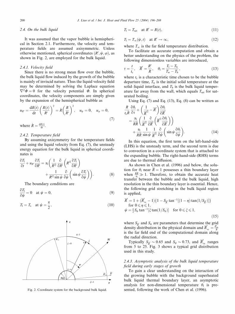
2.4. On the bulk liquid
It was assumed that the vapor bubble is hemispheri-
cal in Section 2.1. Furthermore, the velocity and tem-perature fields are assumed axisymmetric. Unless
otherwise mentioned, spherical coordinates ðR0;w;uÞ, asshown in Fig. 2, are employed for the bulk liquid.
2.4.1. Velocity field
Since there is no strong mean flow over the bubble,
the bulk liquid flow induced by the growth of the bubble
is mainly of inviscid nature. Thus the liquid velocity fieldmay be determined by solving the Laplace equation
r2U ¼ 0 for the velocity potential U. In spherical
coordinates, the velocity components are simply given
by the expansion of the hemispherical bubble as
uR0 ¼ dRðtÞdt
RðtÞR0
� �2
¼ _RRR0
� �2
; uw ¼ 0; uu ¼ 0;
ð7Þwhere _R ¼ dRðtÞ
dt .
2.4.2. Temperature field
By assuming axisymmetry for the temperature fields
and using the liquid velocity from Eq. (7), the unsteady
energy equation for the bulk liquid in spherical coordi-
nates is
oTlot
þ uR0oTloR0 ¼ al
1
R02o
oR0 R02 oTloR0
� ��
þ 1
R02 sinwo
owsinw
oTlow
� ��: ð8Þ
The boundary conditions are
oTlow
¼ 0 at w ¼ 0; ð9Þ
Tl ¼ Ts at w ¼ p2; ð10Þ
r
z
R’
ψ
R(t)
∞
R ′
R ′ξ
η
∞′R
0=ξ
1=ξ
0=η
1=η
Fig. 2. Coordinate system for the background bulk liquid.
Tl ¼ Tsat at R0 ¼ RðtÞ; ð11Þ
Tl ¼ T1ðw; tÞ at R0 ! 1; ð12Þwhere T1 is the far field temperature distribution.
To facilitate an accurate computation and obtain a
better understanding on the physics of the problem, the
following dimensionless variables are introduced,
s ¼ ttc; R
0 ¼ R0
R; hl ¼
Tl � TbTw � Tb
; ð13Þ
where tc is a characteristic time chosen to be the bubble
departure time, Tw is the initial solid temperature at thesolid–liquid interface, and Tb is the bulk liquid temper-
ature far away from the wall, which equals Tsat for sat-urated boiling.
Using Eq. (7) and Eq. (13), Eq. (8) can be written as
R
tc _R
ohlos
þ 1
R02
�� R
0�ohl
oR0
¼ alR _R
1
R02
o
oR0 R
02 ohl
oR0
� �� �
þ alR _R
1
sinw1
R02
o
owsinw
ohlow
� �: ð14Þ
In this equation, the first term on the left-hand-side
(LHS) is the unsteady term, and the second term is due
to convection in a coordinate system that is attached to
the expanding bubble. The right-hand-side (RHS) terms
are due to thermal diffusion.
As shown in Chen et al. (1996) and below, the solu-
tion for hl near R ¼ 1 possesses a thin boundary layer
when R _Ral� 1. Therefore, to obtain the accurate heat
transfer between the bubble and the bulk liquid, high
resolution in the thin boundary layer is essential. Hence,
the following grid stretching in the bulk liquid region
is applied,
R0 ¼ 1þ ðR0
1 � 1Þf1� SR0 tan�1½ð1� gÞ tanð1=SR0 Þ�gfor 06 g6 1;
w ¼ p2Sw tan�1½n tanð1=SwÞ� for 06 n6 1;
ð15Þwhere SR0 and Sw are parameters that determine the grid
density distribution in the physical domain and R01 ¼ R0
1R
is the far field end of the computational domain alongthe radial direction.
Typically SR0 � 0:65 and Sw � 0:73, and R
01 ranges
from 5 to 25. Fig. 3 shows a typical grid distribution
used in this study.
2.4.3. Asymptotic analysis of the bulk liquid temperature
field during early stages of growth
To gain a clear understanding on the interaction of
the growing bubble with the background superheated
bulk liquid thermal boundary layer, an asymptotic
analysis for non-dimensional temperature hl is pre-
sented, following the work of Chen et al. (1996).
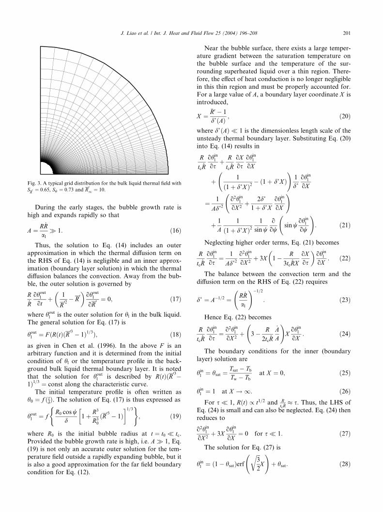
Fig. 3. A typical grid distribution for the bulk liquid thermal field with
SR0 ¼ 0:65, Sw ¼ 0:73 and R01 ¼ 10.
J. Liao et al. / Int. J. Heat and Fluid Flow 25 (2004) 196–208 201
During the early stages, the bubble growth rate is
high and expands rapidly so that
A ¼ R _Ral
� 1: ð16Þ
Thus, the solution to Eq. (14) includes an outer
approximation in which the thermal diffusion term on
the RHS of Eq. (14) is negligible and an inner approx-
imation (boundary layer solution) in which the thermal
diffusion balances the convection. Away from the bub-
ble, the outer solution is governed by
R_R
ohoutl
otþ 1
R02
�� R
0�ohoutl
oR0 ¼ 0; ð17Þ
where houtl is the outer solution for hl in the bulk liquid.
The general solution for Eq. (17) is
houtl ¼ F ðRðtÞðR03 � 1Þ1=3Þ; ð18Þas given in Chen et al. (1996). In the above F is an
arbitrary function and it is determined from the initial
condition of hl or the temperature profile in the back-
ground bulk liquid thermal boundary layer. It is noted
that the solution for houtl is described by RðtÞðR03�1Þ1=3 ¼ const along the characteristic curve.
The initial temperature profile is often written as
h0 ¼ f ðzdÞ. The solution of Eq. (17) is thus expressed as
houtl ¼ fR0 cosw
d1
�(þ R3
R30
ðR03 � 1Þ�1=3)
; ð19Þ
where R0 is the initial bubble radius at t ¼ t0 � tc.Provided the bubble growth rate is high, i.e. A � 1, Eq.(19) is not only an accurate outer solution for the tem-
perature field outside a rapidly expanding bubble, but it
is also a good approximation for the far field boundary
condition for Eq. (12).
Near the bubble surface, there exists a large temper-
ature gradient between the saturation temperature on
the bubble surface and the temperature of the sur-
rounding superheated liquid over a thin region. There-fore, the effect of heat conduction is no longer negligible
in this thin region and must be properly accounted for.
For a large value of A, a boundary layer coordinate X is
introduced,
X ¼�R0 � 1
d�ðAÞ ; ð20Þ
where d�ðAÞ � 1 is the dimensionless length scale of the
unsteady thermal boundary layer. Substituting Eq. (20)
into Eq. (14) results in
R
tc _R
ohinlos
þ R
tc _R
oXos
ohinloX
þ 1
ð1þ d�X Þ2
� ð1þ d�X Þ
!1
d�ohinloX
¼ 1
Ad�2o2hinloX 2
þ 2d�
1þ d�XohinloX
!
þ 1
A1
ð1þ d�X Þ21
sinwo
owsinw
ohinlow
!: ð21Þ
Neglecting higher order terms, Eq. (21) becomes
R
tc _R
ohinlos
¼ 1
Ad�2o2hinloX 2
þ 3X 1
�� R
3tc _RX
oXos
�ohinloX
: ð22Þ
The balance between the convection term and the
diffusion term on the RHS of Eq. (22) requires
d� ¼ A�1=2 ¼ R _Ral
!�1=2
: ð23Þ
Hence Eq. (22) becomes
R
tc _R
ohinlos
¼ o2hinloX 2
þ 3
� R
2tc _R
_AA
!XohinloX
: ð24Þ
The boundary conditions for the inner (boundary
layer) solution are
hinl ¼ hsat ¼Tsat � TbTw � Tb
at X ¼ 0; ð25Þ
hinl ¼ 1 at X ! 1: ð26ÞFor s � 1, RðtÞ / t1=2 and R
tc _R� s. Thus, the LHS of
Eq. (24) is small and can also be neglected. Eq. (24) then
reduces to
o2hinloX 2
þ 3XohinloX
¼ 0 for s � 1: ð27Þ
The solution for Eq. (27) is
hinl ¼ ð1� hsatÞerfffiffiffi3
2
rX
!þ hsat: ð28Þ

202 J. Liao et al. / Int. J. Heat and Fluid Flow 25 (2004) 196–208
For s � 1, by matching the outer and inner solutions
given by Eqs. (19) and (28), the uniformly valid
asymptotic solution of the bulk liquid temperature for
the saturated boiling problem considered here is ob-tained,
hl ¼ fR0 cosw
d1
�(þ R3
R30
R03
�� 1��1=3)
þ ðhsat � 1Þerfcffiffiffi3
2
rX
!; ð29Þ
where hsat ¼ Tsat�TbTw�Tb
and erfc is the complimentary error
function. Eq. (29) is an asymptotic solution for hl validfor s � 1.
The asymptotic solution given by Eq. (29) for the li-
quid thermal field provides an analytical framework tounderstand: (1) how the temperature field of back-
ground superheated bulk liquid boundary layer influ-
ences the temperature hl near the vapor bubble throughthe function f ; (2) how the bubble growth RðtÞ and li-
quid thermal diffusivity affect the liquid thermal field hlthrough the rescaled inner variable X as defined in Eqs.
(20) and (23); and (3) how the folding of the temperature
contours near the bubble occurs through the dependenceof cosw term in Eq. (29). More importantly, from a
computational standpoint, it provides: (1) an accurate
measure on the thickness of the rapidly moving thermal
boundary layer; and (2) a reliable guideline for esti-
mating the adequacy of computational resolution in
order to obtain an accurate assessment of heat transfer
to the bubble.
2.5. Initial conditions
The computation must start from a very small but
non-zero initial time s0, so that Rðs0Þ is sufficiently small
at the initial stage. To obtain enough temporal resolu-
tion for the initial rapid growth stage and to save
computational effort for the later stage, the following
transformation is used,
s ¼ r2: ð30Þ
Thus a constant ‘‘time step’’ Dr can be used in the
computation.
The initial temperature profile inside the superheated
bulk liquid thermal boundary layer plays an importantrole to the solution of hl, which in turn affects the heat
transfer to the bubble through the dome.
There exist both experimental and theoretical studies
that have considered the bulk liquid temperature profile
in the vicinity of a vapor bubble. Hsu (1962) estimated
the temperature profile of the superheated thermal layer
adjacent to the heater surface and found the layer to be
quite thin; thus the temperature gradient inside the
thermal layer is almost linear. However, beyond the
superheated layer the temperature is held essentially
constant at the bulk temperature due to strong turbulent
convection. The experimental study by Wiebe and Judd(1971) revealed similar results. It was found that the
superheated bulk liquid thermal boundary layer thick-
ness, d, decreases with increasing wall heat flux due to
enhanced turbulent convection. A high wall heat flux
results in increased bubble generation, and the bulk li-
quid is stirred more rapidly by growing and departing
vapor bubbles. To estimate the superheated layer
thickness, Hsu (1962) used a thermal diffusion modelwithin the bulk liquid. Han and Griffith (1965) used a
similar model and estimated the thickness to be
d ¼ffiffiffiffiffiffiffiffiffiffipaltw
p; ð31Þ
where tw is the waiting period. The thermal diffusion
model often over-estimates the thermal layer thickness,
as it neglects the turbulent convection, which is quite
strong as reported by Hsu (1962) and Wiebe and Judd(1971).
Generally, the bulk liquid temperature profile is al-
most linear inside the superheated thermal boundary
layer, and remains essentially uniform at the bulk tem-
perature Tb beyond the superheated background ther-
mal boundary layer. Accordingly, the initial condition
for the bulk liquid thermal field used in the numerical
solution is given by
h0 ¼1� z
d ; z < d;0; zP d:
ð32Þ
In the asymptotic solution, the discontinuity of ohl=ozin the above profile causes the solution for hl to be
discontinuous. For clarity, the following exponentialprofile is employed in representing the asymptotic
solution
h0 ¼ exp�� zd
�: ð33Þ
2.6. Solution procedure
An Euler backward scheme is used to solve Eq. (14).
A second-order upwind scheme is used for the convec-
tion term and a central difference scheme is used for the
thermal diffusion terms.
After the bulk liquid temperature field is obtained,
the solid heater temperature field is solved, and the
bubble radius RðsÞ is updated using Eq. (3) and Euler’sexplicit scheme. The information for RðsÞ is a necessary
input in Eq. (14). Although the solution for RðsÞ is onlyfirst-order accurate in time, the OðDsÞ accuracy is not a
concern here because a very small Ds has to be used to
ensure sufficient resolution during the early stages.
Typically, n ¼ 104 time steps are used.

J. Liao et al. / Int. J. Heat and Fluid Flow 25 (2004) 196–208 203
3. Results and discussion
3.1. Asymptotic structure of liquid thermal field
To gain an analytical understanding of the liquid
thermal field near the bubble and to validate the accuracy
of the computational treatment for the thin unsteady
thermal boundary layer, comparison between the com-
putational and the asymptotic solutions for hl near thebubble surface is first presented. As mentioned previ-
ously, the validity of the outer solution of the asymptotic
analysis only requires A � 1, which is satisfied undermost conditions due to rapid vapor bubble growth. The
inner solution is valid for s � 1 in addition to A � 1.
The comparison is presented for bubble growth in
saturated liquid with A ¼ 14000. The initial temperature
profile follows Eq. (33) and dRc¼ 0:5, in which Rc is the
bubble radius at tc. There are 200 and 50 grid intervals
along the R0- and w-directions, respectively. The grid
stretching factors are SR0 ¼ 0:65 and Sw ¼ 0:73 for thecomputational case.
Fig. 4 compares the temperature profiles between the
asymptotic and numerical solutions at s ¼ 0:001, 0.01,
R'-1
θ l
10-3 10-2 10-1 100 101
0.9
0.8
0.7
0.6
0.5
0.4
0.3
0.2
0.1
0
1
θ l
0.9
0.8
0.7
0.6
0.5
0.4
0.3
0.2
0.1
1
ψ=0 (Numerical)o
ψ=40 (Numerical)o
ψ=71 (Numerical)o
ψ=0 (Asymptotic)o
ψ=40 (Asymptotic)o
ψ=71 (Asymptotic)o
τ=0.001
_
ψ=0 (Numerical)o
ψ=40 (Numerical)o
ψ=71 (Numerical)o
ψ=0 (Asymptotic)o
ψ=40 (Asymptotic)o
ψ=71 (Asymptotic)o
τ=0.1
R'-1
10-3 10-2 10-1 100 101_
Fig. 4. Comparison of the asymptotic and the numerical solutio
0.1, and 0.3 for w ¼ 0�, 40�, and 71�. There are two
important points to be noted. First of all, it is seen that
the temperature gradient is indeed very large near the
bubble surface because the unsteady thermal boundarylayer is very thin. Secondly, numerical solutions agree
very well with the asymptotic solutions at s ¼ 0:001 and
0.01. The excellent agreement between the numerical
and analytical solutions indicates that the numerical
treatment in this study is correct. At s ¼ 0:1 and 0.3, the
asymptotic inner solution given by Eq. (29) is no longer
accurate, while the outer solution remains valid because
A � 1 is the only requirement. At s ¼ 0:1 and 0.3 thenumerical solution matches very well with the outer
solution. This again demonstrates the integrity of the
present numerical solution over the entire domain due to
sufficient computational resolution near the bubble
surface and removal of undesirable numerical diffusion
through the use of second-order upwind scheme in the
radial direction for Eq. (14).
The large temperature gradient near the dome causeshigh heat transfer from the superheated liquid to the
vapor bubble through the dome. This large gradient
results from the strong convection effect that is caused
ψ=0 (Numerical)o
ψ=40 (Numerical)o
ψ=71 (Numerical)o
ψ=0 (Asymptotic)o
ψ=40 (Asymptotic)o
ψ=71 (Asymptotic)o
τ=0.3
θ l
0.9
0.8
0.7
0.6
0.5
0.4
0.3
0.2
0.1
1
θ l
0.9
0.8
0.7
0.6
0.5
0.4
0.3
0.2
0.1
0
1
R'-1
10-3 10-2 10-1 100 101_
ψ=0 (Numerical)o
ψ=0 (Asymptotic)o
ψ=40 (Numerical)o
ψ=40 (Asymptotic)o
ψ=71 (Numerical)o
ψ=71 (Asymptotic)o
τ=0.01
R'-1
10-3 10-2 10-1 100 101_
ns at s ¼ 0:001, 0.01, 0.1 and 0.3 for w ¼ 0�, 40�, and 71�.

204 J. Liao et al. / Int. J. Heat and Fluid Flow 25 (2004) 196–208
by the rapid bubble growth (see Eq. (14) for the origin in
the governing equation and Eq. (19) for the explicit
dependence on the bubble growth). Thus the bulk liquid
in the superheated boundary layer supplies a sufficientamount of energy to the bubble.
To capture the dynamics of the unsteady boundary
layer, a sufficient number of computational grids is re-
quired inside this layer. The asymptotic analysis gives an
estimate for the unsteady boundary layer thickness on
the order of d� � 3ffiffiffiffiffiffiffiffiffi14000
p ¼ 0:025, which agrees with the
numerical solution in Fig. 4. At s ¼ 0:01 in Fig. 4, the
discrete numerical results are presented. There are about23 points inside the layer of thickness d� ¼ 0:025. Thisprovides sufficient resolution for the temperature profile
in the unsteady thermal boundary layer. In contrast,
most computational studies on the thermal field around
the bubble dome reported in the open literature have
insufficient grid resolution adjacent the dome, which
leads to an inaccurate heat transfer assessment.
Fig. 5 shows the effect of parameter A on theasymptotic solution. When A is large, the asymptotic
and numerical solutions agree very well. The discrep-
ancy between asymptotic and numerical solutions inside
the unsteady thermal boundary layer increases when Adecreases. However, the outer solution remains valid for
the far field even when A becomes small.
The temperature contours shown in Fig. 6 are diffi-
cult to obtain experimentally. Only recent progress inholographic thermography permits such measurements.
Ellion (1954) has stated that there exists an unsteady
thermal boundary layer contiguous to the vapor bubble
during the bubble growth. Recently, Mayinger (1996)
used a holography technique to capture the folding of
the temperature contours during subcooled nucleate
τ=0.01ψ=40o
100001000
10010
A=14000
Asymptotic
Numerical
θl
0.9
0.8
0.7
0.6
0.5
0.4
0.3
0.2
0.1
-0.1
0
1
R'-1
10-3 10-2 10-1 100 101_
Fig. 5. Effect of parameter A on the liquid temperature profile near
bubble.
boiling. Although his study considered subcooled
nucleate boiling, the pattern of the temperature distri-
bution near the bubble dome by Mayinger (1996) is very
similar to that shown in the Fig. 6. It is expected thatexperimental evidence of contour folding in saturated
nucleate boiling will be reported in the future.
3.2. Constant heater temperature bubble growth in the
experiment of Yaddanapudi and Kim (2001)
In the experiment of Yaddanapudi and Kim (2001),
single bubbles growing on a heater array kept at nomi-nally constant temperature were studied. The liquid used
is FC-72, and the wall superheat is maintained at 22.5
�C, so that Jacob number is 39. The bubble shape in the
early stage appears to be hemispherical. To calculate the
heat flux from the microlayer to the vapor bubble in the
present model, the microlayer wedge angle / or constant
c1 in Eq. (4) must be determined. Neither / nor c1 has
been measured. However, the authors have reported theamount of wall heat flux from the wall to the bubble
through an equivalent bubble diameter deq assuming
that the wall heat flux is the only source of heat entering
the bubble. Since in the present model this heat flux is
assumed to pass through the microlayer, it may be used
to evaluate the constant c1 via trial and error. The
superheated thermal boundary layer thickness d of the
bulk liquid in Eq. (32) is also a required input. Thecomputed growth rate RðtÞ is matched with the experi-
mentally measured RðtÞ in order to determine d. The
simulation is carried out only for the early stage of
bubble growth. This is because after t ¼ 6–8� 10�4 s the
base of the bubble does not expand anymore, and the
bubble shape deviates from a hemisphere. Furthermore,
there is the possibility of the microlayer being dried out
in the latter growth stages as a result of maintaining aconstant wall temperature, as was observed by Chen
et al. (2003).
Fig. 7 shows the computed equivalent bubble diam-
eter deqðtÞ, together with the experimentally determined
equivalent deqðtÞ. In the present model, deq is calculated
using
qvhfg dVbdt
¼Z
� kloTml
on
����z¼LðrÞ
dAm; ð34Þ
where Vb ¼ p6d3eq. The heat flux includes only that from
the microlayer and this allows c1 to be evaluated. For
deq, to match the measured data as shown in Fig. 7, it
requires c1 ¼ 3:0.Fig. 8 compares the computed bubble diameter
dðtÞ ¼ 2RðtÞ and those reported by Yaddanapudi andKim (2001). In Fig. 8, d ¼ 30 lm is used in addition to
c1 ¼ 3:0 in matching the predicted bubble growth with
measured data. The good agreement obtained can be
partly attributed to the adjustment in the superheated

0.9
0.88
0.85
0.8
0.77
0.75
0.7
0.98
0.96
0.94
0.92
R'-10 0.5 1.51 2
0
0.5
1
1.5
2
0
0.5
1
1.5
2
0
0.5
1
1.5
2
0
0.5
1
1.5
2
_
R'-10 0.5 1.51 2_
R'-10 0.5 1.51 2_
R'-1
0 0.5 1.51 2_
τ=0.01
0.9
0.8
0.75
0.65
0.6
0.55
0.5
0.45
0.4
0.35
τ=0.1
0.7
0.6
0.5
0.4
0.3
0.25
0.2
0.95
0.9
0.85
0.8
0.75
0.65
0.15
τ=0.3
0.4
0.3
0.2
0.15
0.9
0.8
0.7
0.6
0.5
0.1
0.05
τ=0.9
Fig. 6. The computed isotherms near a growing bubble in saturated liquid at s ¼ 0:01, 0.1, 0.3, and 0.9.
J. Liao et al. / Int. J. Heat and Fluid Flow 25 (2004) 196–208 205
bulk liquid thermal boundary layer thickness d. Becausethe heat transfer to the bubble (through the microlayer
and through the dome) is of two different mechanisms,
the good agreement over the range is an indication of
the correct physical representation by the present model.Fig. 9 shows the total heat entering bubble and the
respective contribution from the microlayer and from
the unsteady thermal boundary layer. The contribution
from the unsteady thermal boundary layer accounts for
about 70% of the total heat transfer. It was reported by
Yaddanapudi and Kim (2001) that approximately 54%
of the total heat is supplied by the microlayer over the
entire growth cycle. Since, the simulation is only carriedout for the early stage of bubble growth, it is difficult to
compare the microlayer contribution to heat transfer
reported by Yaddanapudi and Kim (2001) with that
predicted by current model. At the end, the bubble ex-
pands outside the superheated boundary layer and
protrudes into the saturated bulk liquid. The heat
transfer from dome thus slows down. Hence, the 54%
for the entire bubble growth period dose not contradict
a higher percentage of contribution computed from the
unsteady thermal boundary layer during the early
stages.Fig. 10 shows the computed temperature contours
associated with Yaddanapudi and Kim’s (2001) experi-
ment for the estimated d and c1. Folding of the tem-
perature contours is clearly observed in the simulation
for saturated boiling.
3.3. Effect of bulk liquid thermal boundary layer thickness
d on bubble growth
Since the superheated bulk liquid thermal boundary
layer thickness, d, determines how much heat is stored in
the layer, it is instructive to conduct a parametric study
on the effects bubble growth with varying d. All
parameters are the same as those used in Yaddanapudi

t (s)
d(t)
(m)
0 0.0002 0.0004 0.0006 0.00080
5E-05
0.0001
0.00015
0.0002
0.00025
0.0003
0.00035
0.0004
0.00045
0.0005
d (t) present modeleqd (t) measurementeq
Fig. 7. Comparison of the equivalent bubble diameter deq for the
experimental data of Yaddanapudi and Kim (2001) and that computed
for heat transfer through the microlayer ðc1 ¼ 3:0Þ.
d(t) present modeld(t) measurement
d(t)
(m)
0
5E-05
0.0001
0.00015
0.0002
0.00025
0.0003
0.00035
0.0004
0.00045
0.0005
t (s)0 0.0002 0.0004 0.0006 0.0008
Fig. 8. Comparison of bubble diameter, dðtÞ, between that computed
using the present model and the measured data of Yaddanapudi and
Kim (2001). Here, c1 ¼ 3:0 and d ¼ 30 lm.
heat
(J)
0
2E-06
4E-06
6E-06
8E-06
1E-05
1.2E-05
1.4E-05
1.6E-05
total heat entering the bubbleheat from micorlayerheat from bulk liquid thermal boudary layer
t (s)0 0.0002 0.0004 0.0006 0.0008
Fig. 9. Comparison between heat transfer to the bubble through the
vapor dome and that through the microlayer.
206 J. Liao et al. / Int. J. Heat and Fluid Flow 25 (2004) 196–208
and Kim’s (2001) experiment except that d is varied.
Hence the influence of the superheated thermal bound-
ary layer thickness d on the bubble growth is eluci-
dated.
Fig. 11 shows the effect on the bubble growth rate of
varying d (from 1 to 100 lm). The thicker the bulk liquid
thermal boundary layer, the faster the bubble grows. A
large d implies a larger amount of heat is stored in thebackground bulk liquid surrounding the bubble. It is
also clear that when d approaches zero, the bubble
growth rate becomes unaffected by the variation of d.
The reason is when d is small, most of heat supplied for
bubble growth comes from the microlayer and the
contribution from the dome can be neglected.
It is also noted that for d ¼ 100 lm, if the bubble
eventually grows to about several millimeters, the effect
of the bulk liquid thermal boundary layer is negligibleon RðtÞ for most of the growth period except at the very
early stages. Physically, this is because the bubble dome
is quickly exposed to the saturated bulk liquid so that it
is at thermal equilibrium with the surroundings. For
small bubbles, it will be immersed inside the thermal
boundary layer most of time. Hence the effect of the
bulk liquid thermal boundary layer becomes significant
for the bubble growth.The microlayer angle / and the superheated bulk li-
quid thermal liquid boundary layer thickness d are the
required inputs to compute bubble growth in the present
model. However, neither of these parameters is typically
measured or reported in bubble growth experiments. It
is strongly suggested that the bulk liquid thermal
boundary layer thickness d be measured and reported in
future experimental studies. For a single bubble study, din the immediate neighborhood of the nucleation site
should be measured.
4. Conclusions
In this study, a physical model is presented to predict
the early stage bubble growth in saturated heteroge-neous nucleate boiling. The thermal interaction of the
temperature fields around the growing bubble and vapor
bubble together with the microlayer heat transfer is
properly considered. The structure of the thin unsteady

0.005
0.050.10.30.50.7
0.9
t=0.96ms
0.005
0.050.10.30.50.70.9
t=0.36ms
0.005
0.050.1
0.3
0.5
0.7
0.9
t=0.12ms
0.05
0.1
0.2
0.3
0.4
0.5
0.6
0.7
0.8
0.9
R'-11.5 2
00 0.5 1
0.5
1
1.5
2
0
0.5
1
1.5
2
0
0.5
1
1.5
2
0
0.5
1
1.5
2
_
R'-11.5 20 0.5 1_
R'-11.5 20 0.5 1_
R'-11.5 20 0.5 1_
t=0.0012ms
Fig. 10. The computed isotherms in the bulk liquid corresponding to the thermal conditions reported by Yaddanapudi and Kim (2001).
t(s)
d(m
)
0 0.0002 0.0004 0.0006 0.0008 0.0010
0.0001
0.0002
0.0003
0.0004
0.0005
0.0006
0.0007
δ=100 µm
δ=50 µm
δ=30 µm
δ=10 µm
δ=5 µmδ=1 µm
Fig. 11. Effect of bulk liquid thermal boundary layer thickness d on
bubble growth.
J. Liao et al. / Int. J. Heat and Fluid Flow 25 (2004) 196–208 207
liquid thermal boundary layer is revealed by the
asymptotic and numerical solutions. The existence of a
thin unsteady thermal boundary layer near the rapidly
growing bubble allows for a significant amount of heat
flux from the bulk liquid to the vapor bubble dome,
which in some cases can be larger than the heat transfer
from the microlayer. The experimental observation byYaddanapudi and Kim (2001) on the insufficiency of
heat transfer to the bubble through the microlayer is
elucidated. For thick superheated thermal boundary
layers in the bulk liquid, the heat transfer though the
vapor bubble dome can contribute substantially to the
vapor bubble growth.
Acknowledgements
This work was supported by NASA Glenn Research
Center under contract NAG3-2750 and NASA Kennedy
Space Center.

208 J. Liao et al. / Int. J. Heat and Fluid Flow 25 (2004) 196–208
References
Akiyama, M., Tachibana, F., Ogawa, N., 1969. Effect of pressure on
bubble growth in pool boiling. Bulletin of JSME 12, 1121–1128.
Bai, Q., Fujita, Y., 2000. Numerical simulation of bubble growth in
nucleate boiling––effects of system parameter. In: Engineering
Foundation Boiling 2000 Conference, Anchorage AL, May 2000,
pp. 116–135.
Chen, T., Klausner, J.F., Chung, J.N., 2003. Subcooled boiling heat
transfer and dryout on a constant temperature microheater. In:
Proceeding of the 5th International Conference on Boiling Heat
Transfer, Montego Bay, Jamaica.
Chen, W., 1995. Vapor bubble growth in heterogeneous boiling. Ph.D
Dissertation, University of Florida.
Chen, W., Mei, R., Klausner, J., 1996. Vapor bubble growth in highly
subcooled heterogeneous boiling. Convective Flow Boiling, 91–97.
Cooper, M.G., 1969. The microlayer and bubble growth in nucleate
pool boiling. International Journal of Heat and Mass Transfer 12,
895–913.
Cooper, M.G., Lloyd, A.J.P., 1969. The microlayer in nucleate pool
boiling. International Journal of Heat and Mass Transfer 12, 915–
933.
Cooper, M.G., Vijuk, R.M., 1970. Bubble growth in nucleate pool
boiling. In: Proceeding of 4th International Heat Transfer Confer-
ence, Paris, vol. 5. Elsevier, Amsterdam, p. B2.1.
Ellion, M.E., 1954. A study of the mechanism of boiling heat transfer.
Ph.D Thesis, California Institute of Technology.
Fyodorov, M.V., Klimenko, V.V., 1989. Vapour bubble growth in
boiling under quasi-stationary heat transfer conditions in a heating
wall. International Journal of Heat and Mass Transfer 32, 227–242.
Han, C., Griffith, P., 1965. The mechanism of heat transfer in nucleate
pool boiling––part I. International Journal of Heat and Mass
Transfer 8, 887–904.
Hsu, Y.Y., 1962. On the size of active nucleation cavities on a heating
surface. Journal of Heat Transfer (August), 207–216.
Koffman, L.D., Plesset, M.S., 1983. Experimental observations of
microlayer in vapor bubble growth on a heated solid. Journal of
Heat Transfer 105, 625–632.
Labunstov, D.A., 1963. Mechanism of vapor bubble growth in boiling
under on the heating surface. Journal of Engineering Physics 6 (4),
33–39.
Lee, R.C., Nydahl, J.E., 1989. Numerical calculation of bubble growth
in nucleate boiling from inception through departure. Journal of
Heat Transfer 111, 474–479.
Mayinger, F., 1996. Advanced experimental methods. Convective
Flow Boiling. Taylor & Francis. pp. 15–28.
Mei, R., Chen, W., Klausner, J., 1995a. Vapor bubble growth in
heterogeneous boiling––I. Formulation. International Journal of
Heat and Mass Transfer 38 (5), 909–919.
Mei, R., Chen, W., Klausner, J., 1995b. Vapor bubble growth in
heterogeneous boiling––II. Growth rate and thermal fields. Inter-
national Journal of Heat and Mass Transfer 38 (5), 921–934.
Moore, F.D., Mesler, R.B., 1961. The measurement of rapid surface
temperature fluctuations during nucleate boiling of water. AIChE
Journal 7, 620–624.
Son, G., Dhir, V.K., Ramannujapu, N., 1999. Dynamics and heat
transfer associated with a single bubble during nucleate boiling on a
horizontal surface. Journal of Heat Transfer 121, 623–631.
van Stralen, S.J.D., Cole, R., Sluyter, W.M., Sohal, M.S., 1975a.
Bubble growth rates in nucleate boiling of water at subatmospheric
pressures. International Journal of Heat and Mass Transfer 18,
655–669.
van Stralen, S.J.D., Sohal, M.S., Cole, R., Sluyter, W.M., 1975b.
Bubble growth rates in pure and binary systems: combined effect of
relaxation and evaporation microlayer. International Journal of
Heat and Mass Transfer 18, 453–467.
van Stralen, S.J.D., 1967. The mechanism of nucleate boiling in pure
liquid and in binary mixtures, parts I–IV. International Journal of
Heat and Mass Transfer 9, 995–1020, 1021–1046; 10, 1469–1484,
1485–1498.
Wiebe, J.R., Judd, R.L., 1971. Superheat layer thickness measure-
ments in saturated and subcooled nucleate boiling. Journal of Heat
Transfer (November), 455–461.
Yaddanapudi, N., Kim, J., 2001. Single bubble heat transfer in
saturated pool boiling of FC-72. Multiphase Science and Technol-
ogy 12 (3–4), 47–63.