The Installation Process for Composite Roofing · The Installation Process for Composite Roofing...
11
The Installation Process for Composite Roofing 3 3:9
-
Upload
nguyenthien -
Category
Documents
-
view
222 -
download
2
Transcript of The Installation Process for Composite Roofing · The Installation Process for Composite Roofing...
The Installation Process for Composite Roofing 3
3:9

World leaders in fall protection
© Copyright Latchways plc 2007 www.latchways.com
Case Study
Thales Telecommunications Factory, Crawley
Objective
To provide a safe, anti-slip, level means of access on Thales Telecommunications factory in Crawley. The roof type was an existing Kingspan KS 1000RW with rooftop mounted plant. The request was in response to a need to comply with WAHR 2005 (Working at Height Regulations 2005) which requires a safe means of access to a place of work and at the same time protect the roof sheet from regular foot traffic.
Solution
Latchways approved contractor worked with the client to develop a specification.
It was recommended that the client should install a Latchways WalkSafe Walkway System in a longways and shortways format that was secured using a standard stitching screws hereby not affecting the warranties/ guarantees of the roofsheet or day to day production in Thales’s manufacturing facilities.
The system was installed in line with Kingspans recommended guidelines.
Project Data
Site:Thales Telecommunications Factory, Crawley
Roof type: Kingspan KS 1000RW
Walkway specification: Flat style longways, white Flat style shortways, white
Project date: November 2006
Total metreage of walkway: 570 m
3:10

The Installation Process for Composite Roofing
Shortways Panels laid to falls
NB: Typical example of shortways panels with some planks removed for clarity and items shown are not to scale.
1 Fixing the Connecting Bars
Lay the walkway sections on the roof in the approximate configuration of the intended route.
Fix the 50 x 6 x 200 mm Aluminium Joining Bars into the protruding end of the three T bearers which protrude 25 mm from the last plank. These are only screwed in one end of the panel to create the male part of the connection, the female section is not screwed to allow for thermal movement.
2 Fixing the Standing Seam Clamp to the Walkway
The Retaining Brackets will need to be positioned approx 1600 mm apart (depends on the roof section), secure a Hi-Bond Self-Adhesive Pad to the reverse side of the Retaining Bracket, then position a Retaining Bracket over the T bearer between the hatched planks and use the supplied Self-Tapping Screw to fix to the roof.
3:11
2
1
1600 mm
3
Fixing
AA

World leaders in fall protection
© Copyright Latchways plc 2007 www.latchways.com
The Installation Process for Composite Roofing
Corner Panel detail laid to falls
NB: Typical example of corner panels with some planks removed for clarity and items shown are not to scale.
1 Shortways to Longways Corner
Corner packs consist of two extra Aluminium Joining Bars and a T bearer. As the T bearers on the longways and shortways section do not line up, an extra T bearer is supplied. Insert the Aluminium Joining Bars into the end T bearers of the shortways panel and secure using Self Tapping Screws supplied.
2 Shortways to Longways Corner (continued)
Slide the extra piece of T bearer over the protruding Aluminium Joining Bar and position this under the longways unit, ensuring that the bearer spans at least two seams.
Now offer the longways walkway up to the shortways panel and interlock the outside section.
3 Alligning Longways Panel to a Shortways Panel
When alligning a longways panel with a shortways panel the two are not connected merely butted up together with a 5 mm gap to allow for thermal expansion.
3:12
2
3
1

Longways Panels laid to falls
NB: Items shown are not to scale.
Walkway Layout
Firstly identify where the walkway is to be fitted and loose lay the standard panels onto roof sheet ensuring both ends of the longer T bearers sit over the roof peaks.
1 Fixing the Walkway
The Retaining Brackets will need to be positioned approx 2000 mm apart (please refer to 3: 11), secure a Hi-Bond Self-Adhesive Pad to the reverse side of the Retaining Bracket, then position a Retaining Bracket over the longer T bearer and use the supplied Self-Tapping Screw to fix to the roof. There is no joining mechanism for longways, just lay the next one in line with a 5 mm gap to allow for thermal expansion.
3:13
Approx 2000 mm
5 mm gap for thermal expansion
1
3
Fixing
AA

World leaders in fall protection
© Copyright Latchways plc 2007 www.latchways.com
The Installation Process for Composite Roofing
Stepped Shortways Panels on pitched roof
NB: The walkway is supplied as individual sections, not component parts and items shown are not to scale.
Fixing adjacent Step Units
Lay the stepped shortways sections on the pitched roof in the approximate configuration of the intended route.
1 Fixing the Stepped Walkway
Secure a Hi-Bond Self-Adhesive Pad to the reverse side of the Step Footing Bearer where the fixings to the roof will be located. Screw through the Step Footing Bearer with the supplied Self-Tapping Screw to fix the Stepped Walkway to the roof. The fixing should be located on the outer foot of the bearers (4 fixings per step).
3:14
1
Fixing
A
A
Approx 400 mm

Stepped Shortways Panels on pitched roof (continued)
NB: The walkway is supplied as individual sections, not component parts and items shown are not to scale.
2 Connecting the step units
Remove the lowest pair of loosely fixed bolts from the Step Footing Bearers of the 2nd step unit.
Next slide down the 2nd step unit ensuring the 2 protruding Aluminium Joining Bars insert into the chambers of the step unit already installed.
3 Fixing the step units together
Drill through the Aluminium Joining Bar, re-fix bolts and tighten.
3:15
3
2
3
World leaders in fall protection
© Copyright Latchways plc 2007 www.latchways.com3:16
The Installation Process for Composite Roofing
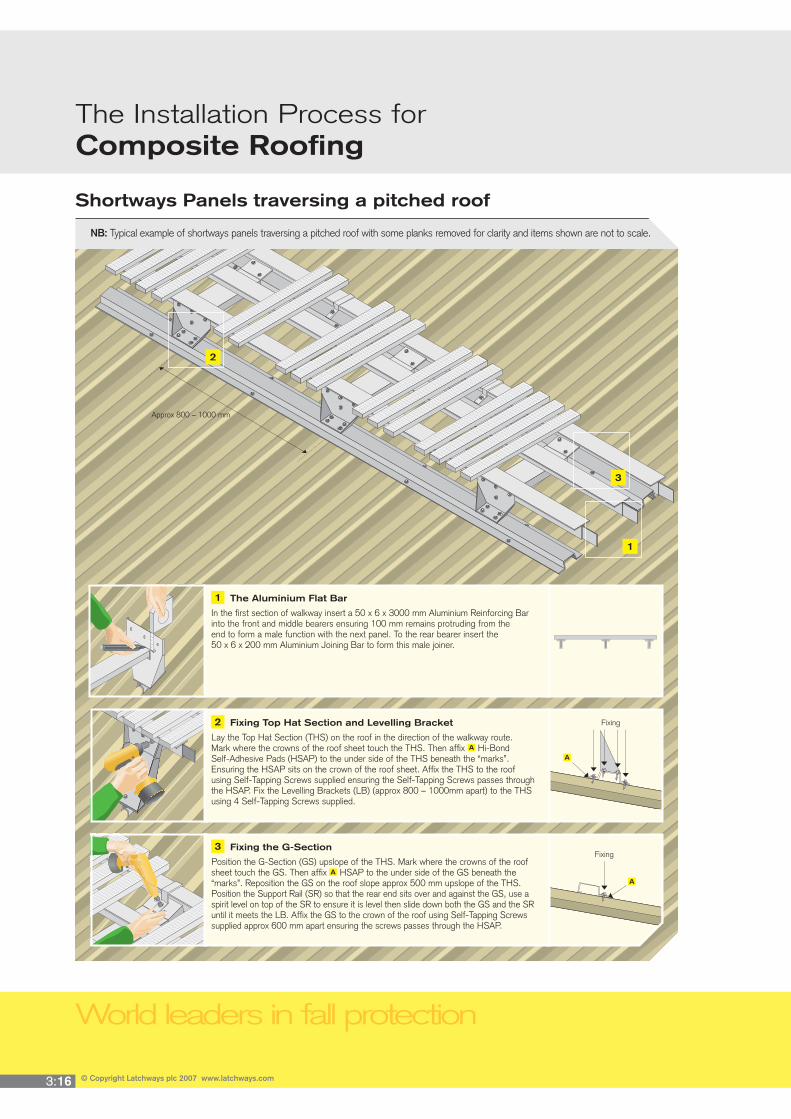
Shortways Panels traversing a pitched roof
NB: Typical example of shortways panels traversing a pitched roof with some planks removed for clarity and items shown are not to scale.
1 The Aluminium Flat Bar
In the first section of walkway insert a 50 x 6 x 3000 mm Aluminium Reinforcing Bar into the front and middle bearers ensuring 100 mm remains protruding from the end to form a male function with the next panel. To the rear bearer insert the 50 x 6 x 200 mm Aluminium Joining Bar to form this male joiner.
2 Fixing Top Hat Section and Levelling Bracket
Lay the Top Hat Section (THS) on the roof in the direction of the walkway route. Mark where the crowns of the roof sheet touch the THS. Then affix Hi-Bond Self-Adhesive Pads (HSAP) to the under side of the THS beneath the “marks”. Ensuring the HSAP sits on the crown of the roof sheet. Affix the THS to the roof using Self-Tapping Screws supplied ensuring the Self-Tapping Screws passes through the HSAP. Fix the Levelling Brackets (LB) (approx 800 – 1000mm apart) to the THS using 4 Self-Tapping Screws supplied.
3 Fixing the G-Section
Position the G-Section (GS) upslope of the THS. Mark where the crowns of the roof sheet touch the GS. Then affix HSAP to the under side of the GS beneath the “marks”. Reposition the GS on the roof slope approx 500 mm upslope of the THS. Position the Support Rail (SR) so that the rear end sits over and against the GS, use a spirit level on top of the SR to ensure it is level then slide down both the GS and the SR until it meets the LB. Affix the GS to the crown of the roof using Self-Tapping Screws supplied approx 600 mm apart ensuring the screws passes through the HSAP.
2
3
Approx 800 – 1000 mm
1
Fixing
Fixing
A
A
AA

3:17
Shortways Panels traversing a pitched roof (continued)
NB: Typical example of shortways panels traversing a pitched roof with some planks removed for clarity and items shown are not to scale.
4 Fixing the Support Rail
Fix the Support Rail to G Section with two Self-Tapping Screws supplied diagionally.
5 Fixing the Levelling Bracket and Support Rail
Once level fix the Support Rail to the Levelling Bracket using a single Self-Tapping Screw supplied.
6 Keeping the Walkway Level
To ensure the next Support Rail is level, take a ‘marker’ to indicate the required distance between the Support Rail and the top of the Levelling Brackets.
4
6
Fixing
Mark here
Approx 800 – 1000 mm
5
Fixing
3

World leaders in fall protection
© Copyright Latchways plc 2007 www.latchways.com3:18
The Installation Process for Composite Roofing
Shortways Panels traversing a pitched roof (continued)
NB: Typical example of shortways panels traversing a pitched roof with some planks removed for clarity and items shown are not to scale.
7 Fixing the Walkway to the Support Rail
Lay the walkway onto the Support Rail hooking the rear T bearer over the G-Section. Secure the walkway to the Levelling Bracket using three Self-Tapping Screws supplied. Make sure the walkway and Support Rail are aligned in such away that you can clearly see the Support Rail through the walkway as a Retaining Bracket will fix the upper end of the walkway to the Support Rail.
8 Fixing the G-Section
Finally use Self-Tapping Screws supplied and Retaining Bracket to fix the walkway to the Support Rail, hooking the Retaining Bracket over the top load bearer.
8
Fixing
Approx 800 – 1000 mm
7
Fixing

3:25
Composite Systems Order FormFor technical assitance, please contact Latchways technical department on +44 (0) 1380 732700. 3
Fax back to +44 (0) 1380 732701
CHOOSE THE PANELS YOU REQUIRE NB: Remember to order your fi xing kit (1 kit per panel).
Shortways Panels laid to falls Part Code Quantity
Panel: 66001-00 WH White
66001-00 SL Silver
Fixing kit: 66101-00 WH White
Longways Panels laid to falls Part Code Quantity
Panel: 66005-00 WH White
66005-00 SL Silver
Fixing kit: 66107-00 WH White
ADD CORNER PACKS YOU REQUIRE
Fixings for Corner Pack Part Code Quantity
Panel: 66106-00 WH White
ADD TRAVERSING PANELS YOU REQUIRE
Shortways Traversing Walkway Part Code Quantity
Panel: 66001-00 WH White
66001-00 SL Silver
Fixing kit: 66109-00 WH White
Angle of roof pitch: º
NB: STEPPED SYSTEMS ARE MADE TO ORDER FOR EACH INDIVIDUAL ROOF
Stepped Walkway
Contact Latchways with the following information:
Roof type:
Angle of roof pitch: º Length of stepped section: metre(s)
x4
x3