The Ins and Outs of Audio Transformers · • Audio Transformers allow one to connect two pieces of...
53
The Ins and Outs of Audio Transformers How to Choose them and How to Use them
Transcript of The Ins and Outs of Audio Transformers · • Audio Transformers allow one to connect two pieces of...
The Ins and Outs of AudioTransformers
How to Choose them andHow to Use them

Steve HoganProduct Development Engineer, Jensen Transformers
1983 – 1989Designed new products and
provided application assistance to Customers
VP Engineering, Jensen Transformers1989-2003
Re-designed entire product line from JE-xxx to JT-xxxusing computer-controlled winding equipment and
improved materials and methods

Audio Transformer Basics
• Audio Transformer is a device consisting of a (driven) primarywinding wound around a core of magnetic material.
• One or more secondary windings wound around the samecore.
• AC Voltage on the primary creates a changing magnetic flux inthe core.
• Changing magnetic flux in the core generates a signal in thesecondary winding(s).
• Signals can be sent from the primary side to the secondaryside without any direct connection since they are magneticallycoupled.

Galvanic Isolation
• Audio Transformers allow one to connect two piecesof equipment together “without connecting themtogether”.
• No direct contact between primary and secondarywindings allows each winding to be at a different DCpotential. Phantom power causes the mic primary tobe +48V higher than the secondary.
• Transformers can break “Ground Loops” and solve“Pin 1 Problems”
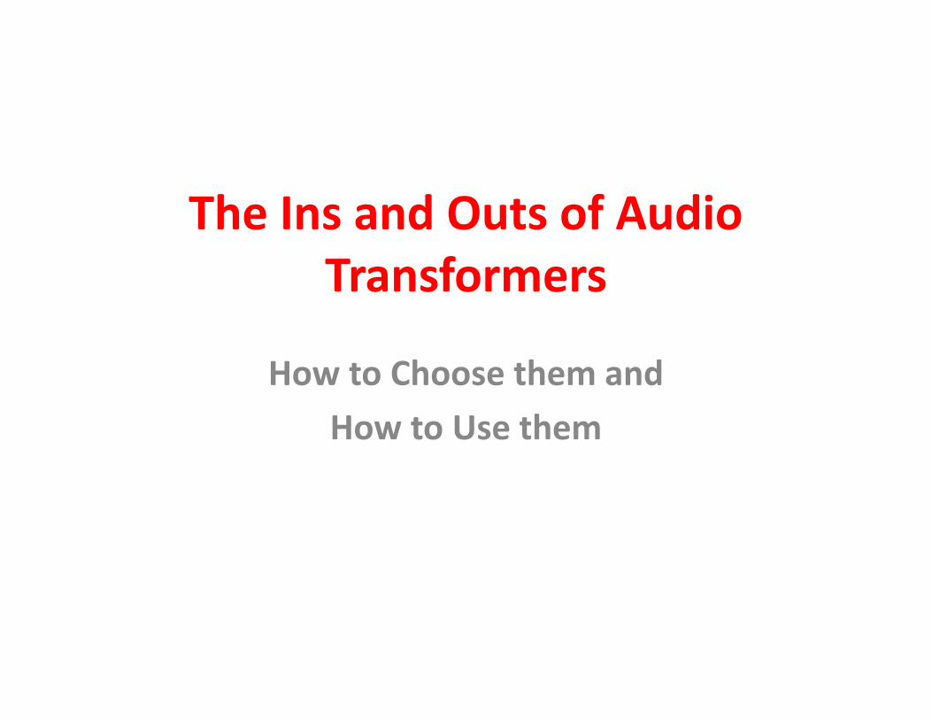
Voltage Transformation
• Transformers can step the secondary voltageup or down relative to the primary voltage.
• Voltage change = Ratio of primary turns andsecondary turns.
• Vpri/Vsec = Npri/Nsec• Power (Volts x Amps) is same on both sides.
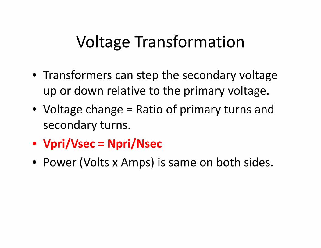
Voltage and Current Relationships
• 10V @ 10mA 1:1 turns ratio = 10V @ 10mA• 10V @ 10mA 1:10 turns ratio = 100V @ 1mA• 10V @ 10mA 10:1 turns ratio = 1V @ 100mA

Source and Load Impedance
• Load Z is the load placed on the secondary winding(s). Itmay be resistive only, or it may be complex withcapacitive or inductive reactance.
• For example a passive equalizer with an input Z of 600Ohms will present a 600 Ohm load Z to the secondary ofan input transformer placed in front of it.
• Source Z is the impedance in series with the voltageproduced by the device driving the primary winding.
• For example, a Shoeps mic with 12 Ohms output Z has asource Z of 12 Ohms to the transformer primary.
Impedance Transformation
• Impedance is changed in BOTH DIRECTIONS.• Zpri/Zsec = (Npri/Nsec)^2• Step-up allows low Z sources (microphones) to
match amplifier noise characteristics forlowest noise
• Step-down allows vacuum tubes to drive low Zspeaker loads.

Impedance Relationships
• 150 Ohm Mic 1:10 turns ratio 150k load resistor• Voltage ratio is 1:10, Impedance ratio is 1:100 (10^2)• Microphone sees a 150K / 100 = 1K5 Load Z• Amplifier sees 150 Ohm mic * 100 = 15K as a source.• Above calculations do not include winding resistances.

Leakage L (Inductance)
• An inductor is an electronic component that opposesthe change in current through the device. Itsreactance (measured in Ohms) increases withincreasing frequency.
• Leakage Inductance is a parasitic series inductance inseries with the transformer. It is caused byincomplete magnetic coupling of the primarywinding to the secondary winding(s).
• It can affect the frequency and transient response ofthe transformer when the secondary has capacitiveloading (like driving a long cable).
Faraday Shields
• Copper Foil Shield between primary andsecondary layers in the transformer assembly.
• Greatly reduces capacitive coupling betweenprimary and secondary, thus giving thetransformer excellent common-moderejection.
• Used in input transformers.
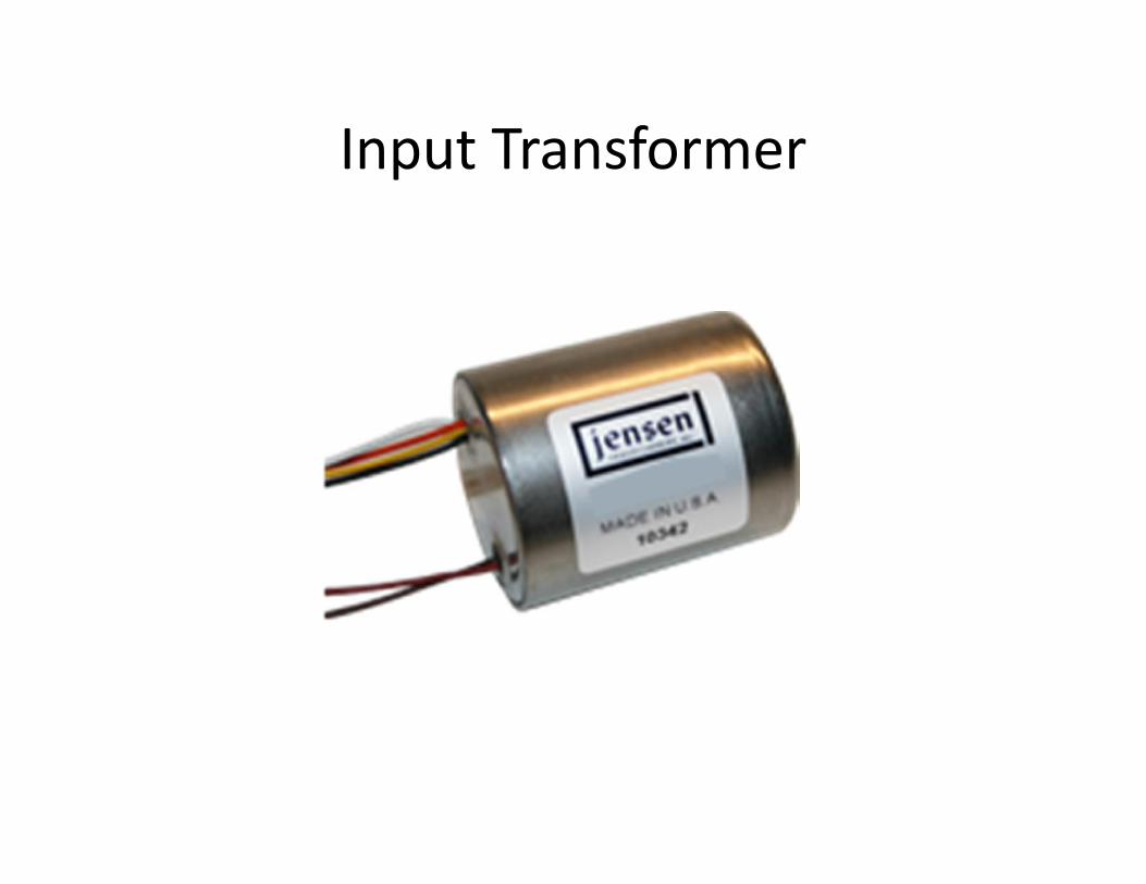
Input Transformer
Input Transformers• Input transformer primary must be fed from various
devices with various source impedances not undercontrol of the user.
• Input transformer secondary can be loaded as requiredfor best performance, since user/designer has control ofthe load.
• Input types typically use multiple interleaved layers ofprimary and secondary to reduce Leakage L, and Faradayshields to provide inputs that are capacitively balancedwith respect to ground.
• Input transformers have excellent CMRR.
Using Input Transformers
• Input type faraday shielded transformer hasexcellent CMRR.
• Input transformers have limited bandwidth andare good at rejecting out-of-band unwantedsignals like RFI.
• Balanced primary can be reversed to obtainpolarity reversal.
• Steps should be taken to eliminate any DC onPrimary, since DC will increase THD and reduceheadroom.

Output Transformer
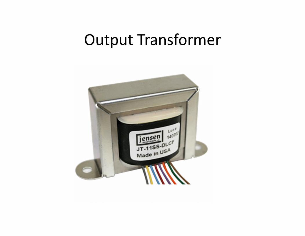
Output Transformer
Output Transformers
• Output transformer primaries are typically drivenby line driver amplifier stages controlled by theuser/designer.
• Output transformer secondaries must drive longcables or short cables, no load or heavy load withno load induced frequency response or transienterrors.
• Typically they are wound multifilar for minimalLeakage L. They have very high winding towinding capacitance, however.

Bifilar Wound OutputTransformer
Primary wire woundsimultaneously side-by-side withsecondary wire.Almost all magneticflux generated by theprimary is “caught” bythe secondary wireright next to it.Winding to windingcapacitance is high.

Using Output Transformers• Large capacitance between windings needs some
precautions: Do not use an output transformer to reversepolarity. It puts a huge capacitive load on the line driveramplifier.
• For symmetrical drive, feed from bridge amp.• Driving primary from single-ended amplifier allows
excellent performance into both Balanced and UnbalancedLoads.
• Drive primary from very DC coupled amplifier with lowoutput Z. DC servo is recommended to eliminate offsets.
• If you must capacitively couple to primary, use very large(>470uF) cap, to reduce sub-sonic resonance peak.

Transformer Distortion
• Transformer THD is 3d harmonic untilsaturation. Musically related (octave + fifth).
• Transformer THD is a Low Frequency Problem.• THD diminishes 6 dB per octave.• Intermodulation Distortion is negligible in
transformers.• THD caused by Source Z (including primary
resistance) being shunted by non-linearprimary inductance.
Types of Core Material
• Three commonly used types of core materialused in audio transformers:
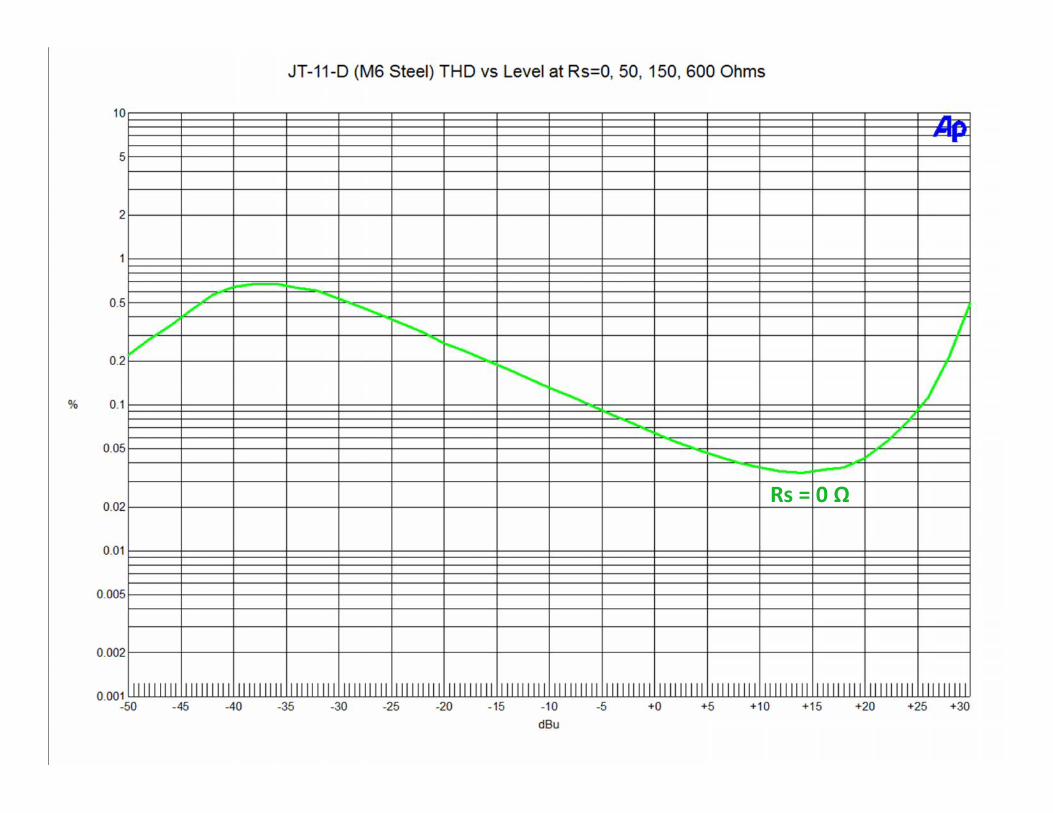
• M6 grain-oriented silicon steel: Used in outputtransformers, especially vacuum tube output.
• 50% nickel alloy: Used in “sound reinforcement”grade output transformers.
• 80% nickel alloy: Used in “recording studio”grade output transformers and all inputtransformers. Handles less maximum level, but ismuch more linear than the others.
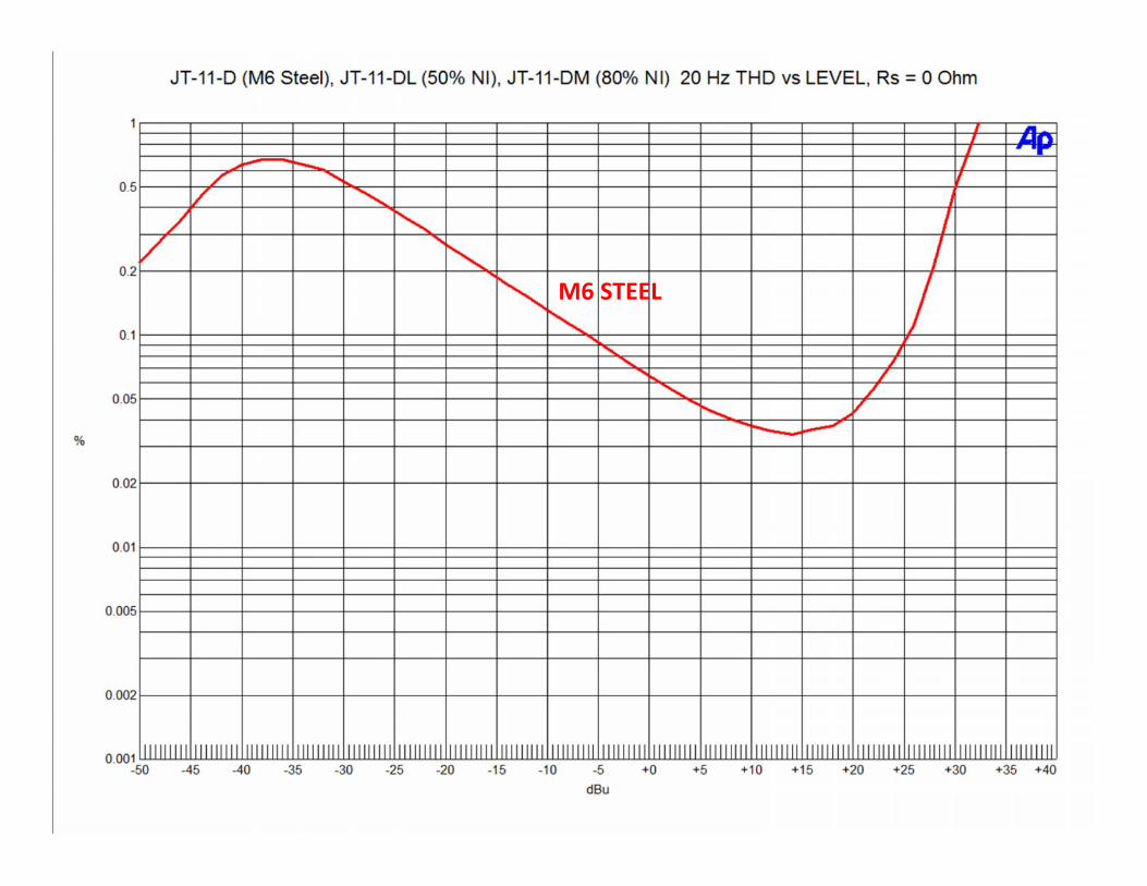
M6 STEEL

M6 STEEL
50 % NICKEL

M6 STEEL
50 % NICKEL
80% NICKEL
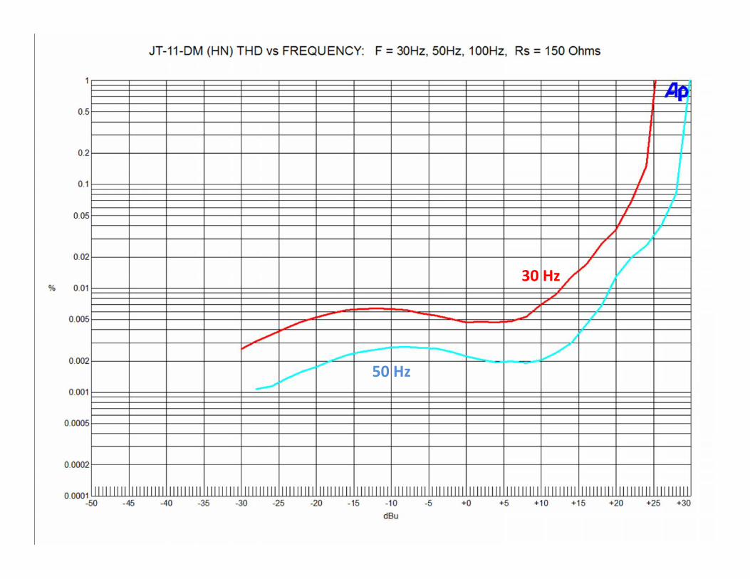
• THD decreases with increasing frequency.• Maximum Level Increases with increasing
frequency.• Following graphs show THD at various
frequencies.

30 Hz
30 Hz
50 Hz

30 Hz
50 Hz100 Hz

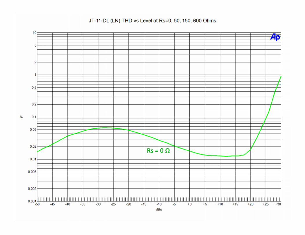
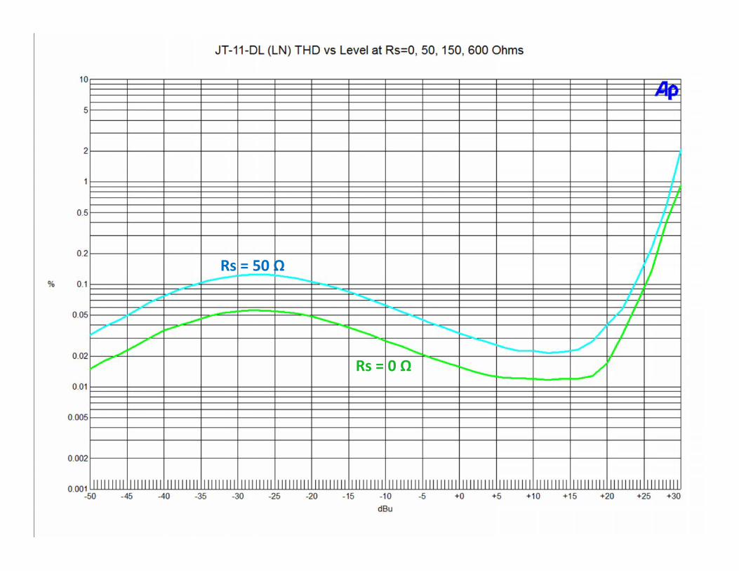
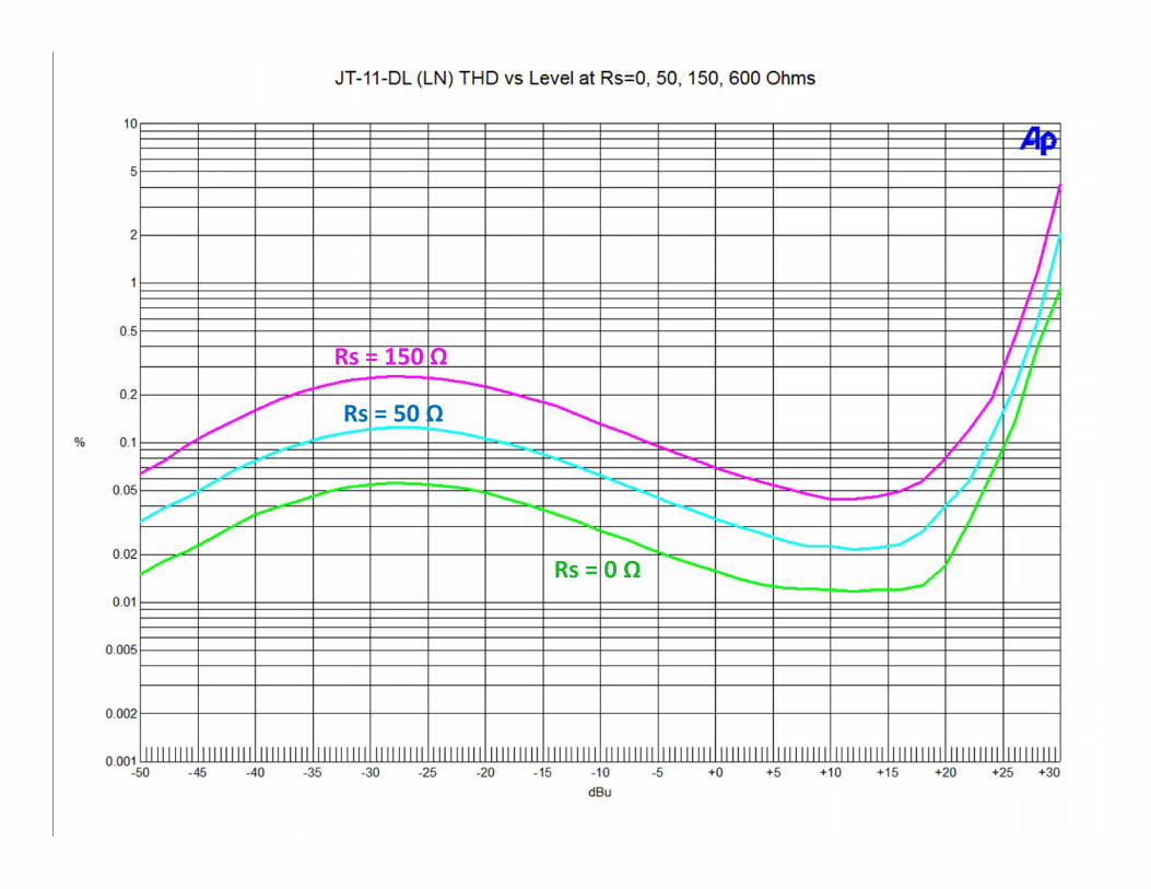
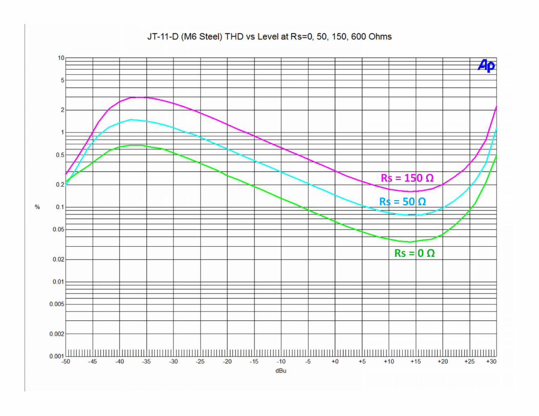
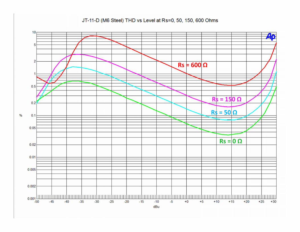
• THD increases with increasing Source Z.• Output transformers should be driven with
lowest possible Source Z.

Rs = 0 Ω

Rs = 0 Ω
Rs = 50 Ω

Rs = 0 Ω
Rs = 50 Ω
Rs = 150 Ω
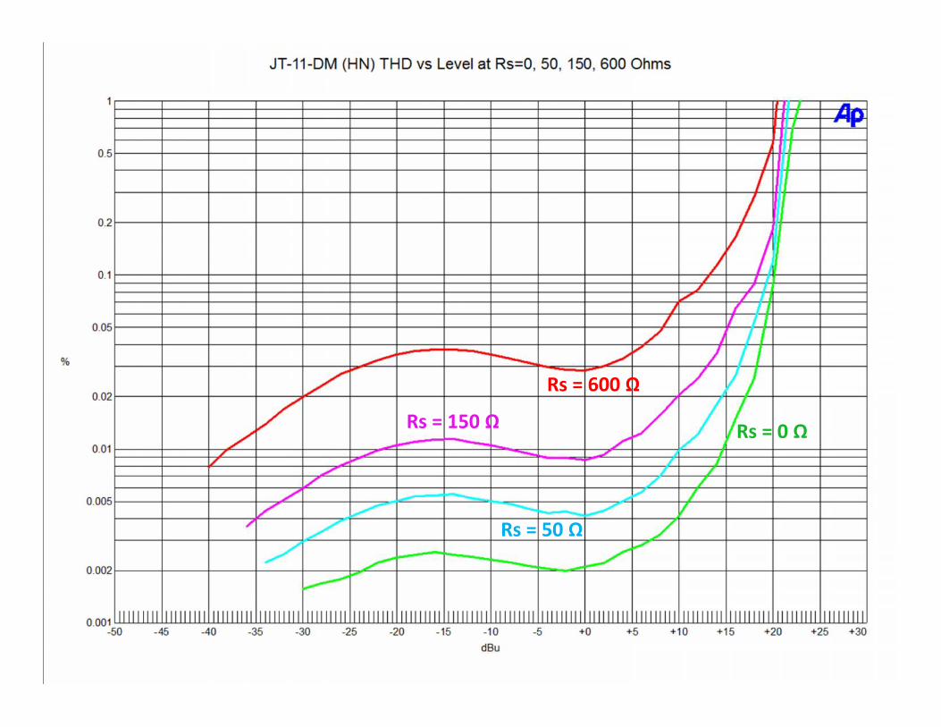
Rs = 0 Ω
Rs = 50 Ω
Rs = 150 Ω
Rs = 600 Ω
Rs = 0 Ω
Rs = 0 Ω
Rs = 50 Ω
Rs = 0 Ω
Rs = 150 Ω
Rs = 50 Ω

Rs = 600 Ω
Rs = 0 Ω
Rs = 150 Ω
Rs = 50 Ω
Rs = 0 Ω

Rs = 0 Ω
Rs = 50 Ω
Rs = 0 Ω
Rs = 50 Ω
Rs = 150 Ω
Rs = 0 Ω
Rs = 50 Ω
Rs = 150 Ω
Rs = 600 Ω
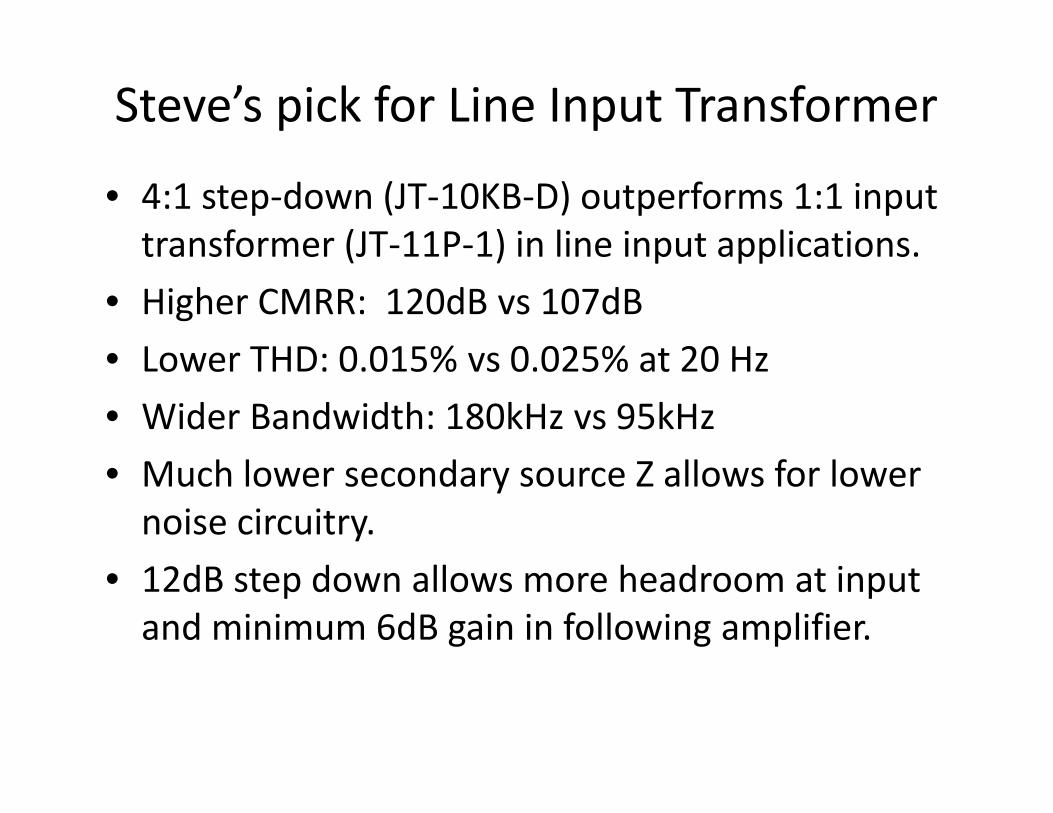
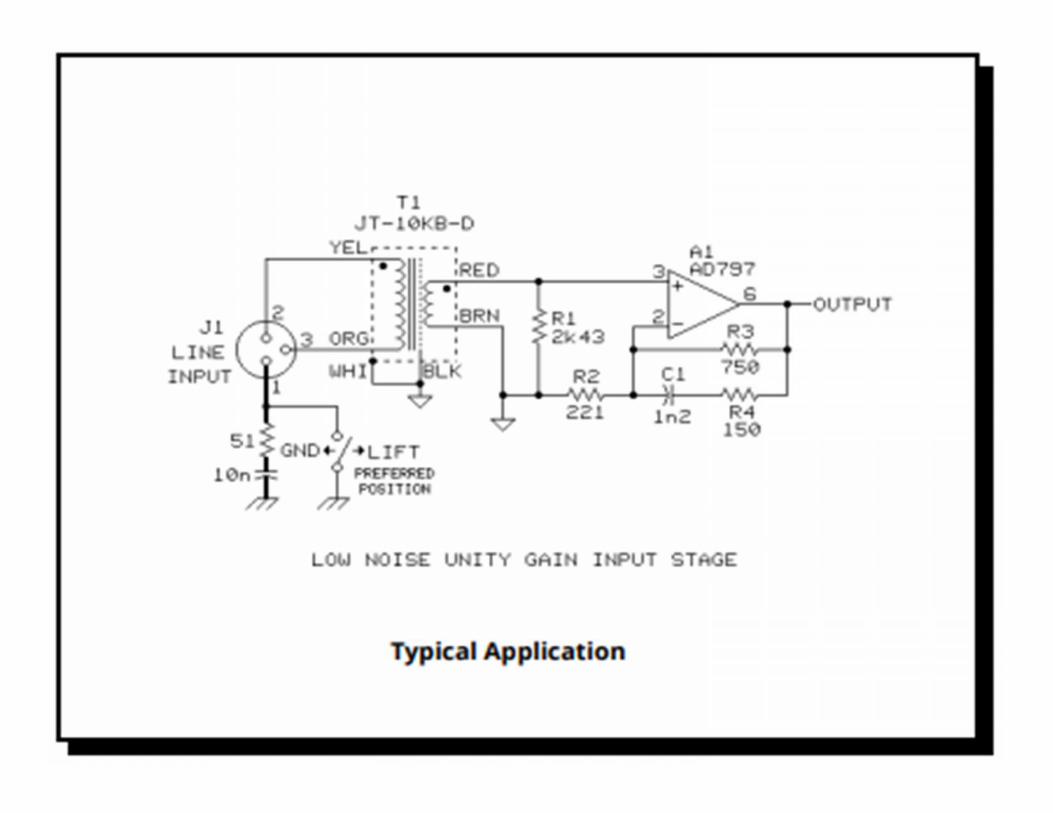
Steve’s pick for Line Input Transformer
• 4:1 step-down (JT-10KB-D) outperforms 1:1 inputtransformer (JT-11P-1) in line input applications.
• Higher CMRR: 120dB vs 107dB• Lower THD: 0.015% vs 0.025% at 20 Hz• Wider Bandwidth: 180kHz vs 95kHz• Much lower secondary source Z allows for lower
noise circuitry.• 12dB step down allows more headroom at input
and minimum 6dB gain in following amplifier.

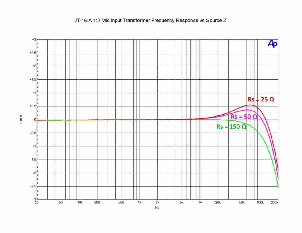
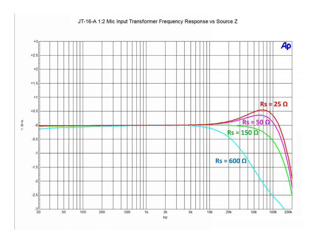
Source Z and Mic Input Transformers
• Microphone output impedance (source Z to input transformer primary)can have a significant effect on the high frequency response and thereforethe transient response of a transformer-balanced mic preamp.
• Source Z will have a lesser effect at low frequencies, with highermicrophone output Z causing slightly more Low Frequency THD and moreLow frequency roll-off.
• The source impedance effects are more pronounced in high-ratio (1:10)step-up mic transformers than in low ratio 1:2 step-up input transformers.
• Adding resistive build-outs to low-Z mics solves this problem completely.Hence “Low-Z mic” switch in the best transformer-based preamps.
• The recording engineer who knows the output Z of his microphones is inthe position to get the best sound from his preamps.
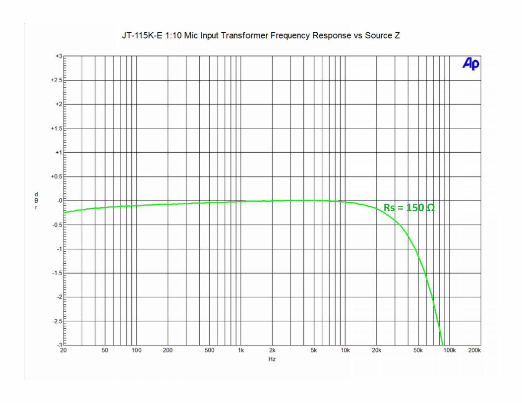
Rs = 150 Ω
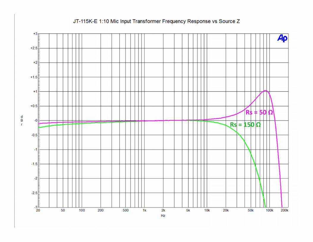
Rs = 150 Ω
Rs = 50 Ω

Rs = 150 Ω
Rs = 25 Ω
Rs = 50 Ω

Rs = 150 Ω
Rs = 600 Ω
Rs = 25 Ω
Rs = 50 Ω

Rs = 150 Ω

Rs = 150 ΩRs = 50 Ω
Rs = 150 ΩRs = 50 Ω
Rs = 25 Ω
Rs = 600 Ω
Rs = 150 ΩRs = 50 Ω
Rs = 25 Ω