Bony pelvis, pelvic walls, and pelvic measurements text_P.pdf

Abstract The angle of the pelvic‐belt connection to the vehicle floor is an important consideration, but this
has not been previously evaluated for wheelchair users. This paper reports on the use of MADYMO multibody
modelling to evaluate the influence of pelvic‐belt angle on pelvic‐belt forces and wheelchair occupant
kinematics and loading in a standardized frontal impact. A model of the 50th percentile male Hybrid III dummy
seated in a manual wheelchair and subjected to a 20g frontal impact pulse was used as the baseline. Results
show the horizontal component of the pelvic‐belt contact force with the abdomen/pelvis remains broadly
constant as the pelvic‐belt angle increased from 30° to 75°, but there was an almost threefold increase in the
vertical component of the pelvic‐belt contact force. The abdomen loading from the pelvic‐belt decreased
dramatically for belt angles in excess of about 45°. The shoulder‐belt force increased with increasing pelvic‐belt
angle. These results indicate that a pelvic‐belt angle in excess of about 45° is necessary to prevent significant
abdominal loading, but pelvic‐belt angles above 60° result in unnecessary increased occupant loading.
Keywords wheelchair user, pelvic‐belt angle, abdomen loading
I. INTRODUCTION
We have estimated that a minimum of 700 wheelchair users in Ireland take at least 500,000 road trips
annually, remaining in their wheelchairs during transit [1]. In the United States, about 1.6 million people
residing outside institutions use wheelchairs [2], and the safety of wheelchair users during transportation is
therefore a key consideration. Many wheelchair users travel in their wheelchairs in converted vehicles, and the
safety features included as standard in vehicle seats and restraint systems must then be emulated by the
wheelchair itself and by the wheelchair and occupant restraint system. Frontal collisions dominate serious
vehicle collisions, and the main focus of wheelchair safety research has been on preventing injury through
occupant retention in frontal impacts (eg [3, 4]) and developing crash protection for pediatric cases (eg [5]).
Ensuring the structural integrity of the wheelchair, tethering the wheelchair to the vehicle and occupant
retention in the wheelchair via Wheelchair Tiedown and Occupant Restraint Systems (WTORS) are the principal
features required to reduce wheelchair occupant injury risk in frontal impact. These findings are embodied in
the voluntary ISO standard 10542 (ISO 2001) (which tests the WTORS), ISO 7176–19 (ISO 2001) (which tests the
entire wheelchair system) and ISO 16840‐4 (ISO 2008) (which tests seating systems independently of the
wheelchair base). A major aspect of wheelchair seating safety is facilitating good pelvic‐belt fit around the bony
portions of the pelvis. The three‐point pelvic and shoulder‐belt system is designed to apply restraint forces to
both the torso and pelvis to accomplish the required velocity change in a given severity collision. For the pelvic‐
belt, the restraint forces should be applied to the bony pelvis rather than the abdomen to prevent underlying
soft tissues being exposed to injury [6]. To achieve this, seats must accommodate the proper fit of belt‐restraint
systems and they must support the occupant throughout the crash so that the belt restraints remain properly
positioned [7]. However, investigation of injury incidents involving wheelchair users during transportation
showed that only 40% of wheelchair seated occupants were correctly using a crashworthy belt restraint system
1 G McDonnell was a student in the Department of Mechanical Engineering, Trinity College, Dublin (Phone: 00353 1 896 2978, Email: [email protected]). Dr. Gina E. Bertocci is a Professor in the Department of Mechanical Engineering and the Endowed Chair of Biomechanics at the University of Louisville. Raymond D’Souza is a Research Engineer in the Department of Mechanical Engineering at the University of Louisville. Dr C. K. Simms is an Assistant Professor of Mechanical Engineering in the Department of Mechanical Engineering and a PI in the Centre for Bioengineering at Trinity College Dublin.
The Influence of Pelvic-belt Angle on Wheelchair Occupant Injury Risk: a simulation study
Gavin McDonnell1, Raymond D’Souza2, Gina Bertocci2, John Tiernan3, Ciaran Simms1
IRC-12-27 IRCOBI Conference 2012
- 194 -

[8, 9]. A common error included positioning of the pelvic‐belts too high over the abdomen or pelvis or belt slack
due to interference by wheelchair components [8, 9]. Our own unpublished survey of wheelchair users at a
Dublin clinic indicates that the current use of fixed vehicle‐mounted wheelchair occupant restraint systems
often results in poor pelvic‐belt fit, and usage rate of vehicle‐mounted wheelchair occupant restraint systems
during transit are often low. To address this issue, wheelchair integrated occupant restraint systems have been
proposed [10, 11], similar to standard practice in conventional car seats. Then the location of the pelvic‐belt
relative to the seat and occupant are well controlled. However, the overwhelming majority of restraint systems
remain vehicle mounted, and this is likely to remain so for some time.
For vehicle mounted restraint systems, the angle of the pelvic‐belt with respect to the vehicle floor (see Fig.
1) is important as it influences the location of the principal contacts with the pelvis and abdomen area and it
also influences the magnitude of the belt loading on the body. Voluntary standards such as ISO 10542 [12]
stipulate that the allowable pelvic‐belt angle should be between 30° and 75° with respect to the horizontal, but
the preferred zone is between 45° and 75°. However, the standards do not reference a scientific study upon
which these recommended angles are based and, from communication with members of ISO TC173, it appears
that these recommended pelvic‐belt angles have not been formally evaluated. Accordingly, this paper reports
on the use of MADYMO multibody modelling to evaluate the influence of pelvic‐belt angle on pelvic‐belt forces
and wheelchair occupant loading in a standardized frontal impact for an adult occupant seated in a manual
wheelchair with a wheelchair tie‐down and occupant restraint system. The goal was to determine whether the
recommended angle range is appropriate.
Fig. 1 ‐ Pelvic‐belt angle of WTORS from ISO 10542 [12]: allowable pelvic‐belt angle are between 30° and 75°
with respect to the horizontal, but the preferred zone is between 45° and 75°.
II. METHODS
Computational Modeling
A previously validated MADYMO [13] model of an occupied adult manual wheelchair was used as a baseline for
this work [14]. The model was originally developed to study wheelchair and WTORS loading, as well as potential
occupant injury risk, making it ideal for the purpose of this paper. The model simulates a frontal impact sled test
of a Hybrid III 50th percentile male dummy seated in an adult manual wheelchair secured with a vehicle‐
anchored WTORS. Finite element components are used for the belt portions in contact with the body, and
multibody belt components in series with the finite element components are used for the straight sections of
the occupant restraint system and for the wheelchair tiedown belts, see Fig. 2.
Fig. 2: The baseline wheelchair frontal impact model [14].
Fig. 3: 20g vehicle acceleration pulse, compliant with ISO 10542.
IRC-12-27 IRCOBI Conference 2012
- 195 -

This model has been previously validated through comparison with sled tests [15], and pelvic‐belt and
shoulder‐belt force, and wheelchair CG, pelvis, chest and head accelerations were found to lie within
acceptance criteria, indicating the model’s ability to reproduce the sled test results.
In this paper, the angle of the pelvic‐belt connection to the vehicle floor with respect to the horizontal was
varied between 30° and 75° in 5° increments in accordance with the permissible range in the voluntary ISO
standard ISO 10542. The Madymo finite element belt‐fitting tool was used to refit the pelvic‐belt for each case.
The belt fitment tool works by specifying a start‐point for the belt, i.e. an anchor point on the sled floor, the
surfaces around which the belt should fit, and finally an end‐point for the belt to terminate, i.e. another anchor
point on the sled floor. In the baseline model both the pelvic‐belt and the shoulder‐belt were anchored to the
same location on the floor. However, since the objective was to determine the influence of pelvic‐belt angle, a
separate anchor point was generated for the shoulder‐belt. Thus the shoulder‐belt was anchored in the same
location for all simulations. A pulse complying with the 20g ISO 10542 frontal impact pulse was applied, see Fig.
3.
The goal was to evaluate the interaction between the pelvic‐belt and the pelvic/abdominal region of a
wheelchair occupant. However, in the baseline model, the occupant was represented by the 50th percentile
male Hybrid III dummy, which has a highly simplified representation of the pelvic and abdominal anatomy. The
lower torso is a cured cylindrical rubber section representing the lumbar spine, while the pelvis is represented
by a vinyl skin/urethane foam moulded over an aluminium casting. In the MADYMO Hybrid III dummy model
this is represented as a single rigid body where the soft urethane foam coated over the hard aluminium casting
has a force penetration curve shown in Fig. 4. As a first approximation, the unaltered MADYMO Hybrid III
dummy model was used, and the influence of pelvic‐belt angle on abdomen/pelvis loading was assessed.
However, although this overall approach is reasonable at describing how a correctly fitted belt would load the
combined abdominal and pelvic region in the event of a collision, in order to test how the belt interacts
separately with the bony and the soft tissues of the abdomen, an alternative approach is necessary. Clearly a
full finite element human body model would achieve this, but there is no validation data available for such an
approach to wheelchair occupant loading. Accordingly, a compromise was taken to amend the validated
MADYMO Hybrid III dummy model to distinguish between the bony pelvis and the soft abdominal tissue by
creating a new bony pelvis within the model consisting of a series of ellipsoids.
Fig. 4. Baseline MADYMO pelvis force‐penetration contact characteristic.
Fig. 5: representation of the pelvic girdle in amended MADYMO Hybrid III model
Accordingly, four new ellipsoids were placed in the Hybrid III ATD to model the bony pelvic bones, see Fig. 5,
and these were given a linear force penetration characteristic (stiffness 6800kN/m) based on the slope of the
end portion of the curve in Fig. 4, i.e. the nominal hard tissue portion of the curve. The force penetration
characteristic of the original pelvis ellipsoids were then modified to represent the soft tissue by using a linear
characteristic (stiffness 68kN/m) based on the initial slope of the force penetration curve in Fig. 4, i.e. the soft
tissue portion of the curve.
The location of the new ellipsoids in the Hybrid III model was estimated and therefore a parametric analysis
was performed to test the influence of the chosen pelvis location on the results. For this parametric analysis,
the ellipsoids representing the Anterior Superior Iliac Spines (ASIS) were moved forwards and backwards (X), up
and down (Z) and left and right (Y) by 2cm each time and the resulting belt force was evaluated.
IRC-12-27 IRCOBI Conference 2012
- 196 -

Accordingly, the results presented consist of
1 Reassessment of the model's ability to reproduce sled test results.
2 Analysis of the horizontal and vertical components of the pelvic‐belt force over a range of pelvic‐belt angles
from 30° to 75° for the following occupant representations:
a. The baseline MADYMO Hybrid III dummy model which treats the pelvic‐belt contact with the body using
a single combined contact characteristic representing the bony pelvis and soft tissue of the abdomen in
series.
b. The amended MADYMO Hybrid III dummy model with separate contacts defined for the bony pelvis and
for the soft tissue of the abdomen.
3 A sensitivity analysis testing the effects of the positioning of the bony pelvis in (2b) was performed.
4 The sagittal plane (XZ) pelvis excursions and shoulder belt loads and lower torso rotations for the amended
MADYMO Hybrid III dummy model are also presented to assist the assessment of the influence of the
different pelvic‐belt angles on occupant kinematics and loading.
III. RESULTS
To test whether the predictive capability of the baseline model was retained, the shoulder and pelvic‐belt time histories were compared to the model results from the previously published model predictions and sled test results [14], see Fig. 6.
(a) Shoulder-belt loading (b) Left pelvic-belt loading
(b) Right pelvic-belt loading (c) Left rear tiedown loading
Fig. 6: Baseline Hybrid III dummy model validation results by comparison to previous MADYMO modeling [14] and sled test data [15].
IRC-12-27 IRCOBI Conference 2012
- 197 -
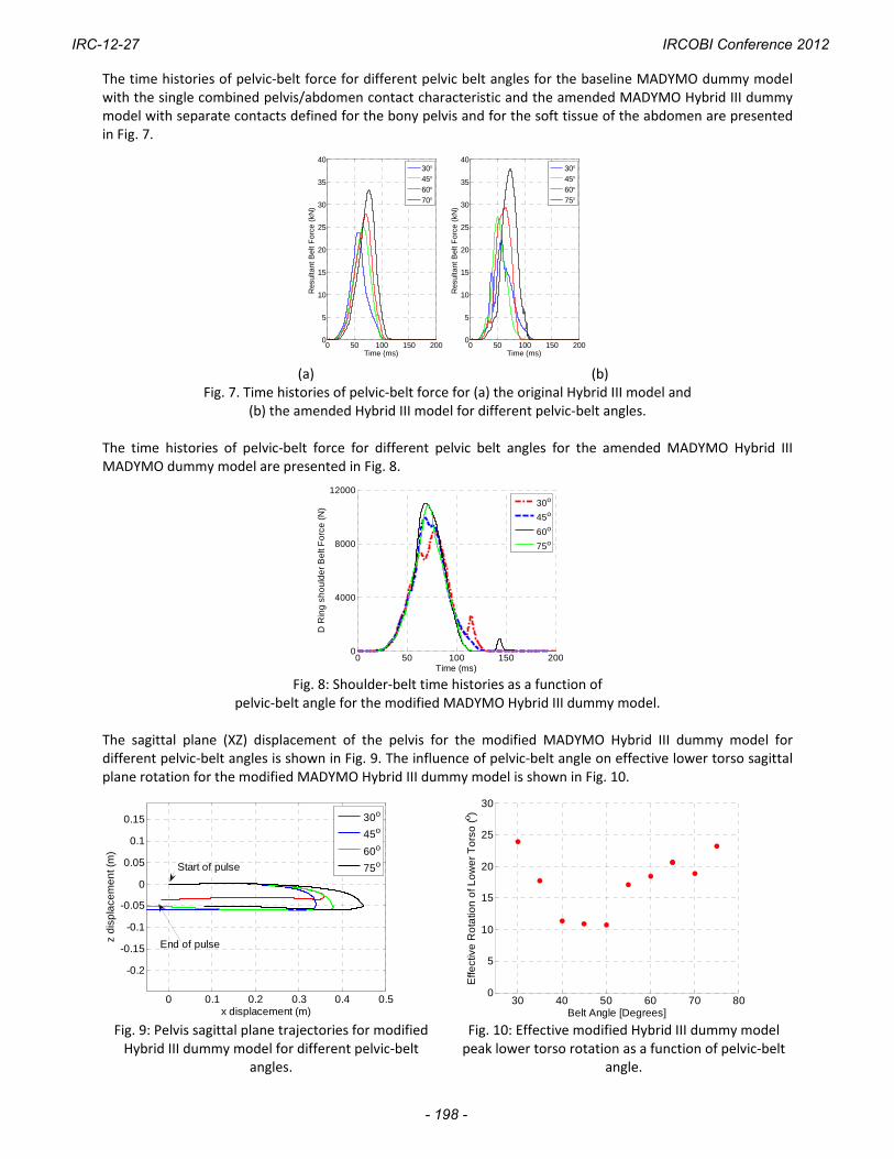
The time histories of pelvic‐belt force for different pelvic belt angles for the baseline MADYMO dummy model with the single combined pelvis/abdomen contact characteristic and the amended MADYMO Hybrid III dummy model with separate contacts defined for the bony pelvis and for the soft tissue of the abdomen are presented in Fig. 7.
0 50 100 150 2000
5
10
15
20
25
30
35
40
Time (ms)
Res
ulta
nt B
elt
For
ce (
kN)
30456075
0 50 100 150 2000
5
10
15
20
25
30
35
40
Time (ms)
Res
ulta
nt B
elt
For
ce (
kN)
30456070
(a) (b)
Fig. 7. Time histories of pelvic‐belt force for (a) the original Hybrid III model and (b) the amended Hybrid III model for different pelvic‐belt angles.
The time histories of pelvic‐belt force for different pelvic belt angles for the amended MADYMO Hybrid III MADYMO dummy model are presented in Fig. 8.
0 50 100 150 2000
4000
8000
12000
Time (ms)
D R
ing
sh
ou
lde
r B
elt
Fo
rce
(N
)
30o
45o
60o
75o
Fig. 8: Shoulder‐belt time histories as a function of
pelvic‐belt angle for the modified MADYMO Hybrid III dummy model. The sagittal plane (XZ) displacement of the pelvis for the modified MADYMO Hybrid III dummy model for different pelvic‐belt angles is shown in Fig. 9. The influence of pelvic‐belt angle on effective lower torso sagittal plane rotation for the modified MADYMO Hybrid III dummy model is shown in Fig. 10.
0 0.1 0.2 0.3 0.4 0.5
-0.2
-0.15
-0.1
-0.05
0
0.05
0.1
0.15
x displacement (m)
z d
isp
lace
me
nt (
m)
Start of pulse
End of pulse
30o
45o
60o
75o
30 40 50 60 70 800
5
10
15
20
25
30
Belt Angle [Degrees]
Effe
ctiv
e R
ota
tion
of L
ow
er
To
rso
(o )
Fig. 9: Pelvis sagittal plane trajectories for modified Hybrid III dummy model for different pelvic‐belt
angles.
Fig. 10: Effective modified Hybrid III dummy model peak lower torso rotation as a function of pelvic‐belt
angle.
IRC-12-27 IRCOBI Conference 2012
- 198 -

The peak horizontal and vertical components pelvic‐belt force versus pelvic‐belt angle for the baseline MADYMO dummy model and the amended MADYMO Hybrid III dummy model are presented in Fig. 11.
30 40 50 60 70 800
0.5
1
1.5
2
2.5
3
3.5x 10
4
Belt Angle ()
Pea
k H
oriz
onta
l Pel
vic
Bel
t F
orce
(N
)
30 40 50 60 70 800
0.5
1
1.5
2
2.5
3
3.5x 10
4
Belt Angle ()
Pea
k V
ertic
al P
elvi
c B
elt
For
ce (
N)
Baseline Hybrid IIIAmended Hybrid III
Baseline Hybrid IIIAmended Hybrid III
Fig. 11: Peak horizontal and vertical components of pelvic‐belt force
for baseline and amended MADYMO Hybrid III dummy models versus pelvic‐belt angle. The nominal abdominal compression force based on the soft tissue contact ellipsoid for the amended MADYMO Hybrid III dummy model is presented in Fig. 12.
20 40 60 800
2
4
6
8
10
12
14
Belt Angle ()
For
ce (
kN)
Fig. 12: Nominal abdomen compression force for amended MADYMO Hybrid III dummy model
with separate bony pelvis and soft tissue abdomen contacts. The results of the sensitivity analysis for the amended Hybrid III model with separate bony pelvis and soft tissue abdomen contacts in which the location of the left and right ellipsoids representing the pelvis (see Fig. 5) were moved ±2cm in each direction (X,Y and Z) to test the influence of the bony pelvis location on the belt angle trends are shown graphically in Fig. 13 and in tabulated form in Tables 1 & 2.
IRC-12-27 IRCOBI Conference 2012
- 199 -

(a) Vertical Force X direction sensitivity
(b) Horizontal Force X direction sensitivity
(c) Vertical Force Y direction sensitivity
(d) Horizontal Force Y direction sensitivity
(e) Vertical Force Z direction sensitivity
(f) Horizontal Force Z direction sensitivity
Fig. 13: Sensitivity analysis for the pelvis location for the
modified MADYMO Hybrid III dummy model.
IRC-12-27 IRCOBI Conference 2012
- 200 -

Table 1: Peak Horizontal Pelvic‐Belt Force
Angle Baseline Amended model [kN]
Max % Change in X Direction
Max % Change in Y Direction
Max % Change in Z Direction
30 20 7 11 18
35 16 23 24 21
40 20 21 7 17
45 21 17 12 20
50 19 16 18 21
55 19 19 12 11
60 20 15 9 11
65 20 19 10 4
70 21 13 9 30
75 22 4 1 1
Table 2: Peak Vertical Pelvic‐Belt Force
Angle Baseline Amended model [kN]
Max % Change in X Direction
Max % Change in Y Direction
Max % Change in Z Direction
30 10 9 12 19
35 16 23 24 10
40 20 21 5 17
45 21 14 12 20
50 19 14 16 20
55 19 17 12 17
60 20 1 12 11
65 20 7 12 10
70 21 15 11 3
75 22 2 1 1
IV. DISCUSSION
In this paper the influence of pelvic‐belt angle on the pelvic‐belt interaction force with the pelvis/abdomen region of adult wheelchair users in frontal impact was analyzed. Detailed finite element occupant models exist, but no appropriate validation data for wheelchair frontal impact are available, and therefore a simplified multibody approach was adopted to provide generalized insight into the relationship between pelvic‐belt angle and bone and soft tissue loading of the pelvis and abdomen region for wheelchair users. The voluntary ISO standard 10542 [12] recommends pelvic‐belt angles between 30° and 75° with respect to the horizontal, but the preferred zone is between 45° and 75°, as shown in see Fig. 1. Due to the nature of the modeling, the focus is on trends rather than absolute values.
Baseline model findings
The baseline MADYMO model employed in this paper [14] has been previously validated by comparison with sled test results [15] and Fig. 6 shows that the model is largely capable of reproducing the time histories of both the experimental and previously published model results for the pelvic‐belt and the shoulder‐belt and the tiedown loading. An anomaly for the magnitude of the right pelvic‐belt force was observed, and this was not
IRC-12-27 IRCOBI Conference 2012
- 201 -

resolved. However, it is concluded that the model is appropriate for the kind of parametric analysis to test the influence of pelvic‐belt angle to which it is applied in this paper. Using the baseline MADYMO Hybrid III model (which treats the pelvic‐belt contact with the body using a
single combined contact characteristic representing the bony pelvis and the soft tissue of the abdomen in series) it is clear that the resultant pelvic‐belt force increases with pelvic‐belt angle, see Fig. 7a. The horizontal component of pelvic‐belt force is not strongly dependent on pelvic‐belt angle, see Fig. 11. However, the predicted vertical component of belt force increases very significantly from 11kN at 30° to 27kN at 70°. This is mainly because a more vertical pelvic‐belt is less efficient at counteracting the horizontal inertial force from the occupant during a frontal impact. Accordingly, on this basis alone, a more horizontal pelvic‐belt would be more appropriate, since this would reduce the magnitude of overall loading to the midbody region.
Amended model findings However, since for correct belt functioning the pelvic‐belt force should be applied to the bony pelvis rather
than the soft tissue of the abdomen [6], a more detailed investigation is necessary. To prevent soft tissue injuries, the contact force between the pelvic‐belt and the soft tissue should be minimized, and this is achieved by passing the load through the bony pelvic girdle. In the modeling this was facilitated by the amendment of the baseline MADYMO Hybrid III dummy model to separate the combined bone and soft tissue contact into two separate contacts,: one representing the interaction between the pelvic‐belt and the soft tissue of the abdomen, and the other representing the interaction between the pelvic‐belt and the bony pelvic girdle. Using this simplified representation, Fig. 7 shows that similar overall belt loading results were observed for the modified MADYMO hybrid III dummy model compared to the baseline MADYMO Hybrid III model (the baseline model was not stable for pelvic‐belt angle of 75° and results for 70° are shown instead in Fig. 7a, hence the apparent large difference for steep angles between Fig. 7a and Fig. 7b). This similarity indicates that the separation of the body contacts employed in this paper has not substantially altered the overall load interaction between the belt and the occupant and it gives a preliminary corroboration to the separated “bone” and “soft tissue“ contacts in the modified model. This separation of the body contacts facilitated distinguishing between a desirable bone loading and an undesirable soft tissue loading from the belt in a generalized manner.
Abdomen Loading The load component transmitted directly to the soft tissues of the abdomen for the modified model is shown
in Fig. 12, which shows a sharp reduction in abdomen force of about 6kN as the pelvic‐belt angle is reduced from 30° to 45°, after which further reductions in abdomen force with increase in pelvic‐belt angle to 70° are much more gradual (about 2kN). Examination of the graphical outputs from the simulations revealed that, for the lower pelvic‐belt angles, the belt failed to catch onto the ellipsoids representing the Anterior Superior Iliac Spines (ASIS) and instead slipped over them, leading to the high ‘soft tissue’ contact load.
Shoulder‐belt Loading The shoulder‐belt loading is influenced by the change in pelvic belt angle, see Fig. 8, which shows that
increasing the angle of the pelvic‐belt from 30° to 75° increases the peak shoulder‐belt load by about 2kN (about 20%). This is because greater occupant excursions occur for higher pelvic‐belt angles, as demonstrated by the sagittal plane pelvis excursions presented in Fig. 9. It is clear from Fig. 9 that a 30° pelvic belt angle results in a slightly larger horizontal excursion (36cm) than a 45° pelvic belt (34cm), because the belt slips over the ASIS and soft tissue compression of the abdomen facilitates further horizontal displacement. For pelvic‐belt angles greater than 45°, the belt does not slip over the ASIS, but the pelvic‐belt is now unaligned with the horizontal inertial load of the body, leading to a large horizontal excursion (45cm) for a 75° pelvic‐belt for this manual wheelchair design. Fig. 9 also shows that the vertically downward excursion of the pelvis increases with pelvic‐belt angle as expected, though the displacement appears to bottom out at 6cm for angles above about 45°. The approximate sagittal plane rotation of the lower torso shown in Fig. 10 indicates that the lowest rotation (ca 11°) occurs for pelvic‐belt angles of around 45°. For very shallow and very steep pelvic belt angles of 30° and 75° respectively, almost 25° of torso rotation occurred.
Submarining risk Viano and Arepally proposed risk criteria for submarining for occupants of automotive seats [16], according to
which the pelvis and torso rearward rotation angle should not exceed 30 degrees, and the H point horizontal and vertical excursions should not exceed 25cm and 5cm respectively. Comparison of these limits to the results
IRC-12-27 IRCOBI Conference 2012
- 202 -

in Fig. 9 and Fig. 10 indicates that the angle limits would not be reached with any of the pelvic‐belt orientations studied, but the horizontal excursions limits are exceeded in all cases, and the vertical limits are exceeded for angles of 45° and above. However, in the sled tests [15] upon which validation of the MADYMO model was based, the pelvic‐belt was at 45°, and submarining was not observed. Therefore, it is unclear to what extent Viano’s automotive seating based criterion can be directly applied to wheelchair seating.
Sensitivity Analysis The results presented in Fig. 12 are influenced by the location of the bony ASIS in the MADYMO model, but
the sensitivity analysis results presented in Fig. 13 and in Tables 1 & 2 indicate that altered position of the ASIS does not alter the trends presented in this paper. All of the results in Fig. 13 (a), (c) and (e) show that there is a broadly linear threefold increase in the vertical component of pelvic‐belt force as the pelvic‐belt angle is increased from 30° to 70°. The horizontal component of pelvic‐belt force over the same range of pelvic‐belt angles is more variable, but Fig. 13 (b), (d), and (f) indicate that the horizontal component of pelvic‐belt force is a weak function of pelvic‐belt angle. Limitations In this simulation study only one crash pulse, one wheelchair type and one occupant size were considered,
and further work should focus on translation of these findings to a range of crash pulses, wheelchairs and wheelchair occupant anthropometrics. Recommendations Overall, these results indicate that a steeper pelvic‐belt angle, between 45°‐70° degrees (as recommended in
the voluntary ISO standards) results in increased occupant pelvic loading. Clearly the intention of the steeper pelvic‐belt angle is to minimize the likelihood of the pelvic‐belt sliding over the top of the ASIS and hence cause compression injuries to the soft tissues of the abdomen. The tendency for this to occur is captured by the model predictions in Fig. 12. However, the results from this paper lead to the preliminary conclusion that this tendency can be effectively eliminated once the pelvic‐belt angle is above about 45°, at least for the configuration considered here of a 50th percentile adult male seated in a manual wheelchair. If only the abdominal soft tissue loading is considered when making recommendations on the range of
allowable and preferred pelvic‐belt angles, then the current ISO 10542 [12] recommendations seem appropriate, as they minimize the risk of abdominal loading. However, recommending a preferred zone of between 45° and 75° means that the vertical component of belt force is significantly increased (see Fig. 11). Therefore, it is suggested that a compromise between protecting the abdominal soft tissues and minimizing the belt force on the pelvis can be achieved if the preferred zone for the pelvic‐belt angle is between 45° and 60° rather than between 45° and 75°. This is illustrated by a qualitative rating shown in Table 3, which shows the benefits and drawbacks of each of the angle groups. While the shallow belt angles (30°‐40°) greatly reduce vertical loading on the occupant, it provides insufficient protection to the abdominal region of the occupant. The steep belt angles (60°‐75°) protect the abdomen area, but this comes at the expense of very high vertical loading to the pelvic girdle of the occupant. A compromise appears to be reached for belt angles between 45° ‐ 60° in which the abdomen protection is much better than for the shallow pelvic‐belt angles and the magnitude of belt loading is also much better than for the steeper pelvic‐belt angles.
Table 3: Qualitative rating of pelvic‐belt angle for horizontal and
vertical pelvic‐belt load and abdominal loading
IRC-12-27 IRCOBI Conference 2012
- 203 -

V. CONCLUSIONS
To the best of our knowledge, this the first study to explicitly consider the effects of the pelvic‐belt angle on wheelchair occupant abdominal/pelvic loading in a controlled computational environment. The preliminary results based on one crash pulse, one wheelchair type and one occupant size indicate that a pelvic‐belt angle of between 60° and 75° is not appropriate. It is proposed instead that a pelvic‐belt angle between 45° and 60° should achieve the twin goals of minimizing abdominal soft tissue loading and the overall belt force on the occupant’s pelvis. However, only one occupant size was analyzed in this simulation study, and further work should focus on translation of these findings to a range of wheelchair occupant anthropometrics.
VI. REFERENCES
1. Simms, CK, Madden B, Tiernan J, and FitzPatrick D, Rear impact neck protection devices for wheelchair users. Journal of Rehabilitation Research and Development, 2009. 46(4): p. 499‐514.
2. Kaye H, Kang T, and LaPlante M, Mobility Device Use in the United States, in Disability Statistics Report 14. 2000, U.S. Department of Education, National Institute on Disability and Rehabilitation Research: Washington, DC.
3. Bertocci GE and van Roosmalen L, Wheelchair caster loading during frontal impact. Assistive Technology, 2003. 15(2): p. 105‐12.
4. Ha D, Bertocci G, Karg P Deemer E, Evaluation of wheelchair sling seat and sling back crashworthiness. Medical Engineering & Physics, 2002. 24: p. 441‐448.
5. Ha D and Bertocci G, Injury risk of a 6‐year‐old wheelchair‐seated occupant in a frontal motor vehicle impact‐‐[`]ANSI/RESNA WC‐19' sled testing analysis. Medical Engineering & Physics, 2007. 29(7): p. 729‐738.
6. Nahum A, and Melvin J, eds. Accidental injury biomechanics and prevention: chapter 8‐ Occupant Restraint Systems. 2002.
7. Adomeit D, Seat design—a significant factor for safety belt effectiveness in Twenty‐Third Stapp Car Crash Conference Paper. 1979.
8. Klinich K, Moore J, Manary M and Schneider L, Use and Performance of Occupant Restraint Systems for Wheelchair Users in Real‐World Crashes. in RESNA. 2006.
9. Schneider L, Klinich KD, Moore JL and MacWilliams JB, Using in‐depth investigations to identify transportation safety issues for wheelchair‐seated occupants of motor vehicles. Medical Engineering & Physics, 2010. 32(3): p. 237‐247.
10. Bertocci GE and Evans J, Injury risk assessment of wheelchair occupant restraint systems in a frontal crash: a case for integrated restraints. Journal of Rehabilitation Research and Development, 2000. 37(5): p. 573‐89.
11. Van Roosmalen L, Bertocci GE, Ha D and Karg P, Wheelchair integrated occupant restraints: feasibility in frontal impact. Medical Engineering and Physics, 2001. 23(10): p. 687‐98.
12. ISO, ISO 10542 Technical systems and aids for disabled or handicapped persons ‐ Wheelchair tiedown and occupant‐restraint systems 2001, International Organisation for Standardisation.
13. MADYMO, MADYMO, Human Models Manual, Version 7.0. TNO Delft, the Netherlands, 2009. 14. Dsouza R and Bertocci GE, Development and validation of a computer crash simulation model of an occupied
adult manual wheelchair subjected to a frontal impact. Medical Engineering & Physics, 2010. 32(3): p. 272‐279.
15. Leary A, Injury risk analysis and design criteria for manual wheelchairs in frontal impacts, School of Engineering, University of Pittsburgh 2001.
16. Viano D and Arepally S, Assessing the Safety Performance of Occupant Restraint Systems. in Proceedings of the 34th Stapp Car Crash Conference. 1990.
IRC-12-27 IRCOBI Conference 2012
- 204 -