The influence of impact direction and axial loading on the ... · direction of the force applied...
38
Accepted Manuscript Title: The influence of impact direction and axial loading on the bone fracture pattern Authors: Haim Cohen, Chen Kugel, Hila May, Bahaa Medlej, Dan Stein, Viviane Slon, Tamar Brosh, Israel Hershkovitz PII: S0379-0738(17)30186-X DOI: http://dx.doi.org/doi:10.1016/j.forsciint.2017.05.015 Reference: FSI 8853 To appear in: FSI Received date: 17-6-2016 Revised date: 19-1-2017 Accepted date: 13-5-2017 Please cite this article as: Haim Cohen, Chen Kugel, Hila May, Bahaa Medlej, Dan Stein, Viviane Slon, Tamar Brosh, Israel Hershkovitz, The influence of impact direction and axial loading on the bone fracture pattern, Forensic Science Internationalhttp://dx.doi.org/10.1016/j.forsciint.2017.05.015 This is a PDF file of an unedited manuscript that has been accepted for publication. As a service to our customers we are providing this early version of the manuscript. The manuscript will undergo copyediting, typesetting, and review of the resulting proof before it is published in its final form. Please note that during the production process errors may be discovered which could affect the content, and all legal disclaimers that apply to the journal pertain.
Transcript of The influence of impact direction and axial loading on the ... · direction of the force applied...

Accepted Manuscript
Title: The influence of impact direction and axial loading onthe bone fracture pattern
Authors: Haim Cohen, Chen Kugel, Hila May, Bahaa Medlej,Dan Stein, Viviane Slon, Tamar Brosh, Israel Hershkovitz
PII: S0379-0738(17)30186-XDOI: http://dx.doi.org/doi:10.1016/j.forsciint.2017.05.015Reference: FSI 8853
To appear in: FSI
Received date: 17-6-2016Revised date: 19-1-2017Accepted date: 13-5-2017
Please cite this article as: Haim Cohen, Chen Kugel, Hila May, Bahaa Medlej,Dan Stein, Viviane Slon, Tamar Brosh, Israel Hershkovitz, The influence ofimpact direction and axial loading on the bone fracture pattern, Forensic ScienceInternationalhttp://dx.doi.org/10.1016/j.forsciint.2017.05.015
This is a PDF file of an unedited manuscript that has been accepted for publication.As a service to our customers we are providing this early version of the manuscript.The manuscript will undergo copyediting, typesetting, and review of the resulting proofbefore it is published in its final form. Please note that during the production processerrors may be discovered which could affect the content, and all legal disclaimers thatapply to the journal pertain.

1
Complete manuscript title: The influence of impact direction and axial loading on the bone
fracture pattern
Haim Cohen a, b* [email protected]
Chen Kugel b ,c [email protected]
Hila May a [email protected]
Bahaa Medlej a [email protected]
Dan Stein a [email protected]
Viviane Slon a, e [email protected]
Tamar Brosh d [email protected]
Israel Hershkovitz a [email protected]
a Department of Anatomy and Anthropology, Sackler Faculty of Medicine, Tel Aviv
University, Tel Aviv 69978, Israel
b National Center of Forensic Medicine,Tel Aviv 61490, Israel
c Sackler Faculty of Medicine, Tel Aviv University, Tel Aviv 69978, Israel
d Laboratory of Fine Measurements, Dental School of Medicine, Tel-Aviv University,
Israel
e Department of Evolutionary Genetics, Max Planck Institute for Evolutionary
Anthropology, 04103 Leipzig, Germany.
Grant sponsors: Dan David Foundation, Tassia and Dr. Joseph Meychan Chair for the History
and Philosophy of Medicine.
*Correspondence: Dr. Haim Cohen, Department of Anatomy and Anthropology, Sackler
Faculty of Medicine, Tel Aviv University, Tel Aviv 69978, Israel
Tel: 972-3-6409495; Fax: 972-3-6408287; E-mail: [email protected]

2
Highlights
We examined the influence of impact direction and axial loading on the bone
fracture pattern.
Five different tests in different directions and loading situations were carried
out.
The impact direction and the presence of axial loading during impact
significantly affected the fracture pattern.
None of our experiments (with and without compression) yielded a "true"
butterfly fracture.
Abstract
The effect of the direction of the impact and the presence of axial loading on fracture
patterns have not yet been established in experimental 3-point bending studies.
Purpose: To reveal the association between the direction of the force and the fracture
pattern, with and without axial loading. Material and methods: A Dynatup Model
POE 2000 (Instron Co.) low energy pendulum impact machine was utilized to apply
impact loading on fresh pig femoral bones (n=50). The bone clamp shaft was adjusted
to position the bone for three-point bending with and without additional bone
compression. Four different directions of the force were applied: anterior, posterior,
lateral, and medial. Results: the impacted aspect can be distinguished from the non-
impacted aspects based on the fracture pattern alone (the most fractured one); the
impact point can be identified on bare bones (the area from which all oblique lines
radiate and/or the presence of a chip fragment). None of our experiments (with and
without compression) yielded a "true" butterfly fracture, but instead, oblique radiating
lines emerged from the point of impact (also known as "false" butterfly). Impacts on
the lateral and anterior aspects of the bones produce more and longer fracture lines
than impacts on the contralateral side; bones subjected to an impact with axial loading
3
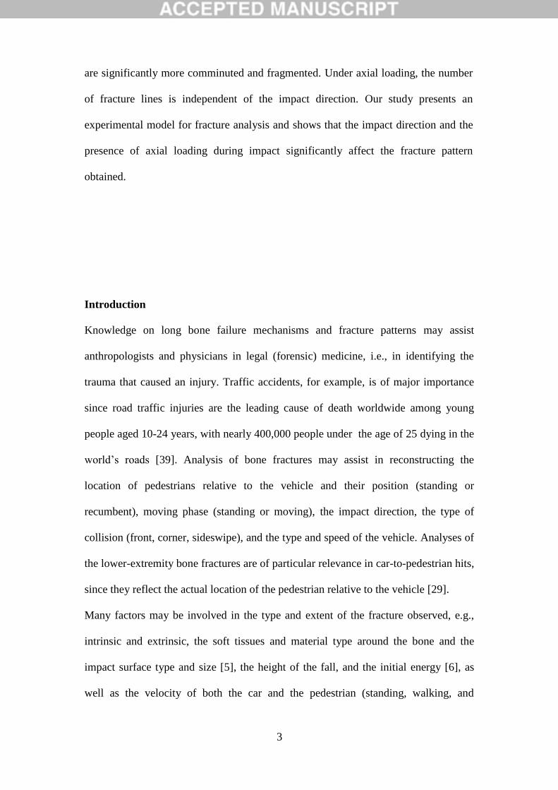
are significantly more comminuted and fragmented. Under axial loading, the number
of fracture lines is independent of the impact direction. Our study presents an
experimental model for fracture analysis and shows that the impact direction and the
presence of axial loading during impact significantly affect the fracture pattern
obtained.
Introduction
Knowledge on long bone failure mechanisms and fracture patterns may assist
anthropologists and physicians in legal (forensic) medicine, i.e., in identifying the
trauma that caused an injury. Traffic accidents, for example, is of major importance
since road traffic injuries are the leading cause of death worldwide among young
people aged 10-24 years, with nearly 400,000 people under the age of 25 dying in the
world’s roads [39]. Analysis of bone fractures may assist in reconstructing the
location of pedestrians relative to the vehicle and their position (standing or
recumbent), moving phase (standing or moving), the impact direction, the type of
collision (front, corner, sideswipe), and the type and speed of the vehicle. Analyses of
the lower-extremity bone fractures are of particular relevance in car-to-pedestrian hits,
since they reflect the actual location of the pedestrian relative to the vehicle [29].
Many factors may be involved in the type and extent of the fracture observed, e.g.,
intrinsic and extrinsic, the soft tissues and material type around the bone and the
impact surface type and size [5], the height of the fall, and the initial energy [6], as
well as the velocity of both the car and the pedestrian (standing, walking, and

4
running) [24]. Better understanding the combined forces that acted on the bone, i.e.,
tension, compression, shearing, torsion, and bending is the key for identifying the a
priori events that led to the fractures.
Fracture patterns are usually classified into 6 classic types: transverse, oblique
or butterfly, spiral, segmental, and comminuted. This classification of fracture
patterns is largely derived from the medical literature where determination of the
stability of the injury, the probable extent of associated soft tissue damage, and the
prognosis for recovery are the primary motivations [10]. However, using this
classification of fractures to reconstruct the causes of trauma is not straightforward.
The biomechanics of long bones has been studied since the 19th century. However,
with long bones most works have dealt with the quasi-static testing of standardized
specimens, in order to determine the material properties rather than the fracture
pattern (e.g., [23][33][34][38]). In 1880, Messerer found that the cracking or tearing
of the bone generally occurred on the convex (tension) side of the bone. In bones
exhibiting a significant bend, crushing was evident on the concave (compression)
side, at the point where the load was applied, before a tearing or tension fracture
occurred [20] (Cited from Kress et al., 1995 [18]). Evans and Lissner [9] further
emphasize, through stresscoat studies, the significance of tensile stresses as the cause
for bone failure. One of the most detailed discussions of tibial impact, including
impactor weight, size, direction, and velocity was carried out by Nyquist et al. [23];
however, the information regarding the fracture pattern was very general and meager.
Another important study on fracture patterns and their relation to impact conditions
was carried out by Kress et al. [18]. Since these early studies, numerous other static
test results have been published and much of these data can be found in the
engineering literature. Many authors have aimed at listing certain patterns of fractures

5
following mechanisms of loading (e.g., [14][21][36]). Most studies describe and
define fracture types in relation to the direction of loading and the loading type
applied, e.g., a transverse fracture resulting from a bending load, an oblique fracture
resulting from compression, and a butterfly fracture resulting from a combination of
bending and compression loads [3][10][11][12][31]. Although there is a consensus
regarding the mechanism that produces certain fracture patterns, competing theories
exist in the medical literature in relation to others. In addition, most studies analyzing
fracture patterns in 3-point bending did not include additional axial compression
loading, defined as when the thigh receives a lateral blow when bearing weight, for
example, pedestrians injured by vehicles. In addition, the information regarding the
nature of the specimens studied was incomplete, and the precise site of impact was
not reported.
Currently, there is no a single study that has inclusively examined the
morphological and metrical characteristics of fractures with regard to the impact
direction of the force applied and the effect of axial loading on the fracture pattern
from a forensic perspective, simulating a situation occurring in pedestrian road traffic
accidents.
Objectives of the study
The objectives of the study were to reveal the association between the direction of
impact loading and the bone fracture pattern and to assess how additional axial
loading influences a fracture pattern, by simulating body weight on a leg (as in a
standing position) during impact.

6
Materials and methods
Experimental set-up: The Dynatup Model POE 2000 (Instron Co.) low energy
pendulum impact machine, shown in Figure 1, was utilized to apply impact loading
on pig femoral bones. Custom-made supports for holding each bone in place during
loading were fabricated. The clamp shaft was designed to support the bone while the
impact load was oriented perpendicularly to the longitudinal axis of the bone (Figure
2). The bone clamp shaft was adjusted to position the bone for three-point bending
with additional bone compression, simulating body weight on a leg (as in a standing
position). The compression forces (in relation to the long axis of the bone) were
generated by moving the clamp plates located at the edges of the bone; the exact
amount of compression forces was adjusted and monitored using the Tension
Compression Load Cell (Vishay Tedea-Huntleigh 615) and a digital monitor
(Rinstrum 310). Two adjustable supports allow the inner loading span along the bone
shaft to be altered, depending on the bone size (Figure 2). Preparation of bones: Fresh
femora of young pigs (5-6 months old) were exposed to the impact loading. Juvenile
bones were selected for this study since road traffic injuries are the leading cause of
death worldwide among young people aged 10-24 (World Health Organization) [39].
The pig bones were obtained fresh and almost clean from an abattoir (on the day of
slaughter). The specimen preparation included careful separation of remnant muscles
and all other soft tissues from the bones, including the periosteum. All bones were
visually examined for macroscopic defects, skeletal disease, or pre-fractures, and later
were stored frozen at −20 °C until testing. The bones were labeled and their lengths
and mid-shaft dimensions were measured. In order to hold the bones stable in the
compression clamps so that compression forces could be applied on all articular
areas, the bones' epiphyses were embedded in transparent polyester resin (Erco E-

7
16®). Preceding the coating process, the bones were thawed with water to room
temperature and stored in a water tank during processing. Four drops of accelerator
solution and 3 ml of hardener solution were inserted into a small plastic container
containing 120 ml of liquid transparent polyester in order to prepare the polyester
solution (the plastic containers were covered on the inside with a thin layer of
Vaseline in order to prevent the polyester from sticking). The bones were inserted into
the empty plastic container with their longitudinal axis perpendicular to the base of
the container and were handled in a fume hood, using a stable handle. In order to
cover the distal epiphysis with polyester, both condyles, in all tests, were set to meet
the bottom of the plastic container (leveling process); the plastic containers were
leveled horizontally using a simple level bar. Following the leveling process, the
polyester solution was poured into the plastic container and left for 30 minutes until
drying and cooling were complete. Testing procedure: A custom-made impactor-body
(tup) was connected to the pendulum of the impact machine. All bones were fractured
in three-point bending under wet conditions. The inner loading span was adjusted
consistently to be 8 cm. The compression force applied along the long bone axis
through the clamps was adjusted consistently to be 25 kg (assuming equal
compression forces on each leg). The bones were set in the compression clamp with
their longitudinal axis perpendicular to the pendulum movement. The tup of the
pendulum (impact body), a half-cylinder shaped-body (10 mm diameter) composed of
stainless steel was adjusted to meet the bone in its mid-span point (the center of the
bone). The longitudinal axis of the tup was oriented perpendicular to the longitudinal
axis of the bone, creating a contact-point impact. The energy of the pendulum (in
Joules) was calculated based on its potential energy at the initial height where the
pendulum was elevated:

8
(1)
M is the mass (kgm), g (9.81 m/sec2) is the gravity acceleration, and h (m) is the
height from which the pendulum was released.
The mass (m) and the pendulum height (h) in Eq. 1 were calculated by
(2)
W is the weight of the body-mass, L is the length of the pendulum arm, and ө is the
angle of the body-mass elevation.
The velocity at the impact was calculated by assuming that all the potential energy
was transferred into kinetic energy (Table 1). That is:
(3)
mghEP
))90sin(1(
Lh
mgW
2
2
1mvmgh
9
The tests: In order to reveal the association between impact directions and fracture
patterns, 40 bones were fractured from four different directions. All tests were
conducted without additional axial loading. In order to reveal the effect of axial
loading on the fracture pattern, 10 bones were laterally impacted under axial loading
(compression). All five tests were conducted under a 3.47 m/sec velocity impact (10
bones in each group).
The following five tests were applied:
Test-1: Lateral impact.
Test-2: Anterior impact.
Test-3: Medial impact.
Test-4: Posterior impact.
Test-5: Lateral impact under axial loading (compression).
The following independent variables were measured either prior or following testing:
1. Bone maximum length: Prior to testing, the maximum length between the
head of the femur and the condyles was measured.
2. Cross-sectional dimensions at the impact point: The lateral-medial and
anterior-posterior diameters were measured prior to testing as well as the
cortical bone thickness following testing. Since the lateral-medial diameters
were significantly higher (4%; p<0.001) than the anterior-posterior diameters,
the moment of inertia of a tube was determined when bending was considered,
based on the direction of impact. In the case of impact from lateral to medial,
the thicknesses of the lateral cortex (T1) and the medial cortex (T2) were
used. In the case of impact from anterior to posterior, the thickness of the
anterior cortex (T4) and the posterior cortex (T3) were used

10
(4)
= External lateral-medial diameter,
Internal lateral-medial diameter,
Thickness of the lateral cortex (T1) + the thickness of the medial
cortex (T2)
Thickness of the posterior cortex (T3) + the thickness of the anterior
cortex (T4)
The following dependent variables were measured following testing:
1. The number of fracture lines: Any fracture line longer than 1 cm was recorded.
Fracture lines may appear in different forms: longitudinal, oblique, transverse, or
polygonal (see below for more details). Fracture lines were defined as
follows:
a. Longitudinal lines: Straight lines running proximally or distally,
parallel to the bone longitudinal axis, toward the epiphysis. The longitudinal
lines may appear in all aspects of the bone (medial, lateral, anterior, and
posterior), but usually they can be found in the area of impact (C-
longitudinal line), in the contralateral aspect (CL- longitudinal line), or in both
aspects. Related observations and measurements include the presence,
number, and location (Figure 3).
64
)( 44
IE ddI
)( jiEI ttdd
)( jiEI ttdd
)( jiEI ttdd
it
jt

11
b. Oblique lines: Fracture lines running at an angle to the long axis of the
bone. Oblique lines usually run proximally or distally toward the epiphysis
and to other aspects of the bone. Oblique fracture lines were defined according
to their direction and propagation, for example, proximal oblique medial
(POM) refers to an oblique line (O) running towards the proximal epiphysis
(P) from the impact point to the medial aspect (M) of the bone. The area
between two oblique lines is "the polygon"; their numbers, location, and
length (mm) have also been recorded (Figure 3).
c. Transverse lines: A horizontal line fully encircles the diaphysis. It appears
ether straight or fractured. It is recorded either as present or absent (Figure 3).
2. Chip fragment: A missing bony part at the point of impact. Related observations
and measurements include the presence and size (circumferential length (mm))
(Figure 3).
Bone preparation for analysis of fracture lines: the post-test procedure: The
cleaning process consisted of five hours of boiling in water with detergent, 20
minutes soaking in 35% Hydrogen Peroxide, and 10 minutes rinsing with water
(before the cleaning process, the polyester coating was removed). All bone fragments
were placed on blotting paper and allowed to dry for 24 hours. Following the cleaning
and drying processes, all bony fragments were reassembled to form a complete bone
using UHU adhesive.
Analysis of fracture lines: The fracture lines were quantitatively analyzed by
measuring the fracture lines’ length using Microscribe® G2X 3D digitizers directly
on the reassembled bones. The X, Y, and Z coordinates of the deviation points along

12
each segment of the fracture line were obtained. The length between each pair of
points was calculated by the 3D Pythagoras Theorem. The total fracture line length
was the sum of the segments’ lengths.
Statistics: The statistical analysis was carried out using SPSS V15. Descriptive
statistics were applied on all data. The ANOVA test was used to analyze the
differences between the group means. A Student's t-test was carried out to detect
significant differences in the parameters’ means between two groups. The Chi-square
test was carried out to reveal associations between categorical variables. The Kruskal-
Wallis test was used to evaluate between-group differences in non-parametric
variables. The P value was set at p<0.05.
Results
This study describes and analyzes fracture patterns in two modes: qualitative and
quantitative. In the quantitative mode, the fracture line measurements are
summarized. In the qualitative mode, schematic illustrations of the fracture patterns
are presented for each test. All four aspects of the bone: anterior, posterior, lateral,
and medial are presented and discussed.
The association between the fracture pattern and the impact direction
The data on the relationships between the fracture characteristics and different impact
directions appear in Tables 1-4. Bone and fracture line metrical characteristics in
different impact directions are presented in Table 1. No significant differences in the
cross-sectional moment of inertia between the femora in the four tests carried out
were found. This implies that factors other than morphometrical differences in the
femur characteristics are responsible for the results in the different tests. The number

13
and length of the fracture lines are clearly associated with the impact direction: the
lateral impact produces the highest number of fracture lines and the longest ones,
whereas the posterior impact produces the smallest number of fracture lines and the
shortest ones (Table 1). The length and number of fracture lines were similar in bones
impacted from the medial and anterior sides (Table 1). A chip fragment on the point
of impact was found in bones subjected to medial, lateral, and anterior impacts. The
largest chip fragment was found on the anterior aspect. Chip size and the number of
fracture lines were independent of the impacted aspect: lateral, medial, anterior, and
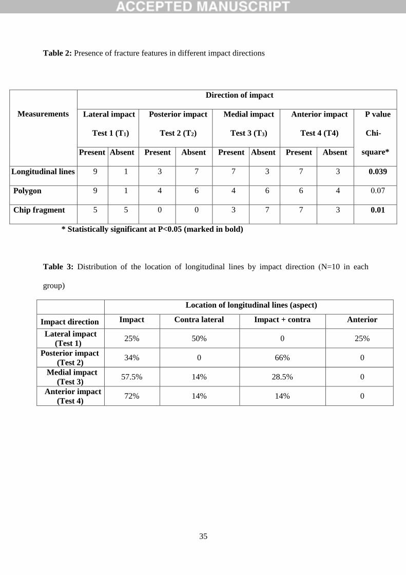
posterior (Table 1). Significant associations were found between the direction of
impact and the number of longitudinal lines and the presence of chip fragments
(Table 2). The largest number of longitudinal fracture lines (n=9) was found in bones
impacted from the lateral side (Table 2). Most longitudinal lines, however, were
found on the contra lateral side (medial side) (Table 3). Similar numbers of
longitudinal lines (n=7) were found in bones subjected to medial and anterior impacts
(Table 2). In these groups, the longitudinal lines were found mostly on the impact
side (57.5% and 72%, respectively) (Table 3). The smallest number of longitudinal
lines was found in bones impacted on the posterior aspect (n=3) (Table 2). The largest
numbers of polygons were found in bones impacted on their lateral side, followed by
bones subjected to an anterior aspect and finally, bones subjected to posterior and
medial impacts (Table 2). Chip fragments were present in 70% of the bones subjected
to an anterior impact, in 50% of bones subjected to a lateral impact, and in 30% of
bones subjected to a medial impact. No chip fragments were found in bones subjected
to a posterior impact. Distributions of longitudinal line locations by impact direction
appear in Table 3. The average numbers of fracture lines by bone aspect and impact
direction appear in Table 4. There is a clear relationship between the direction of the

14
impact and the number of fracture lines regarding the different aspects of the bone.
Except in the case of posterior impacts, most fracture lines are located on the
impacted aspect.
A schematic illustration of the most common fracture pattern, following a
lateral, anterior, medial, and posterior impact (tests 1-4), is presented in Figures 4-7.
In general, only bones subjected to lateral (Figure 4) and anterior (Figure 5) impacts
present a multifragment "false" butterfly pattern, as compared with the relatively
fragmental transverse/oblique pattern in bones subjected to a medial (Figure 6) and
posterior (Figure 7) impact. In bones subjected to a lateral and anterior impact the
transverse T line is absent. Bones subjected to a lateral impact are fractured the most
and present a significantly greater number of long fracture lines, including "false"
butterfly fragment (four oblique-spiral lines), a large number of longitudinal lines in
almost all aspects, and a moderate sized chip fragment at the point of impact (Figure
4). As compared with bones subjected to a lateral impact, bones subjected to anterior
impact also present a multifragment "false" butterfly pattern, however, with a smaller
number and shorter fracture lines (Figure 5). The most marked difference between
bones subjected to an anterior and lateral impact is related to the chip fragment. In
both cases, the chip fragment is located on the impact aspect; however, it is much
larger and more common in bones subjected to an anterior impact (Figure 4 vs. Figure
5). Only in bones subjected to an anterior impact is there a clear resemblance between
the chip fragment shape and the impact body morphology. Bones subjected to a
medial and posterior impact present a fragmental transverse/oblique pattern (Figures
6, 7); however, in bones subjected to a medial impact (Figure 6), a complete
circumferential transverse line is present and a butterfly pattern is less common. In
both cases, only inferior oblique lines are present; however, in bones subjected to a

15
medial impact, the oblique lines originate from a moderate sized chip fragment rather
than ones from a distant origin (such as a short transverse line) as in bones subjected
to a posterior impact. The chip fragment in bones subjected to a medial impact is of
moderate size as in bones subjected to a lateral impact; however, in bones subjected
to a medial impact a long longitudinal line is usually present at the point of impact,
running superiorly or inferiorly toward the epiphysis. Bones subjected to a posterior
impact present the least number of fracture lines, usually with a short transverse line
on the impact aspect only (Figure 7). In all bones subjected to a posterior impact, the
chip fragment at the point of impact is absent, and as in bones subjected to a medial
impact, only inferior oblique lines are usually present, explaining why the butterfly
pattern is less common (Figure 7).
The association between the fracture pattern and the presence of axial loading
Mean values (±SD) for bones and fracture characteristics relating to the association
between the fracture pattern and the presence of axial loading appear in Table 5.
Lateral impact with additional axial loading (compression) produced significantly
more fracture lines than did lateral impact without additional axial loading. Bones
subjected to an impact without axial loading manifest on average one longitudinal
line on the contra lateral aspect. This line is absent in bones subjected to an impact
with axial loading. The bone-chip fragment at the point of impact is significantly
larger in bones tested under axial loading. Differences, although not significant, were
also found in relation to the fracture line length (Table 5). The average number of
fracture lines by bone aspect and axial loading in bones impacted from the lateral
impact appear in Table 6. Under axial loading, the number of fracture lines is similar
on all aspects of the bone; however, without axial loading the number of fracture lines
on the impacted side is significantly greater than on the other aspects (Table 6).
16
A schematic illustration of the most common fracture pattern following lateral impact
with axial loading is shown in Figure 10. As compared with a comminuted or
multifragment "false" butterfly fracture in bones subjected to a lateral impact with
axial loading, fractures in bones subject to a lateral impact without axial loading,
although also presenting a butterfly pattern, are significantly less comminuted and
fragmented (Figure 4). With a lateral impact without axial loading, the butterfly
fragments appear smaller (the oblique lines exhibit a low degree of propagation not
reaching the metaphysis area near the epiphyses). On the lateral (impacted) aspect of
bones subjected to an impact without axial loading, the chip fragment is smaller and
the fracture line between the distal oblique-radial lines and the transverse line is
absent. In these bones, a short longitudinal line is present at the point of impact,
running proximally from a small chip fragment. In cases of impact without axial
loading, only a single longitudinal line is present between the oblique-radial lines on
the anterior aspect as compared with the presence of numerous radiating lines in
bones following an impact with axial loading (see Figure 10).
Discussion
In all tests conducted in this study, the impacted aspect (lateral, medial, anterior, or
posterior) manifested a different fracture pattern from that seen in the non-impacted
aspects. This phenomenon can be used to identify the impact direction, i.e., the
impact point is the area from which all oblique lines radiate. Sometimes it can also be
identified by the presence of a chip fragment. In all experiments carried out, except
for bones subjected to a posterior impact, the impacted aspect was also the most
fractured one.
In this section, three major findings will be discussed: a. the presence of "V-shaped"
radiating fracture lines, b. the differences in the fracture pattern among the impacted

17
aspect (anterior, lateral, medial, and posterior), and c. the effect of axial loading on
the fracture pattern.
V-shaped fracture lines: None of our experiments (with and without compression)
yielded a "true" butterfly fracture, i.e., apex (origin) of V-shaped lines is located
contralateral to the impacted surface. Butterfly fractures are commonly seen in the
lower extremities when the thigh or calf receives a lateral blow when bearing weight,
as with pedestrians injured by vehicles [11]. Assuming that the bone is weaker in
tension than in compression, one would expect to find a transverse fracture line
originating on the contralateral side of the impact and a "true" butterfly pattern
following bending. In this study, however, no "true" butterfly pattern was identified
but rather a "false" butterfly pattern (a wedge-shaped fragment where the apex and
not the base is directed toward the impact site). This "false" butterfly fracture pattern
was manifested in our study by two oblique lines running from the point of impact
superiorly and inferiorly toward the contralateral side: DOA and POA or DOP and
POP with a lateral impact (Figure 4) and POM and DOM or POL and DOL with an
anterior impact (Figure 5). A V-shaped radiating fracture pattern (as described above)
is seen when failure first occurs at the impact site [2]. This is consistent with studies
on vehicle-pedestrian accidents, showing that a “false” wedge-shaped fracture is more
common in cases where the area of contact between the limb and the vehicle elements
is very small [25] (cited from Teresinski, 1999 [37]). Butterfly fractures are
commonly used in forensic cases for establishing the position of a pedestrian in
relation to a motor vehicle [37]. The mechanism underlying this fracture was the
subject of Messerer’s study in the late 19th century [20]. Thereafter, this rule
concerning the location of the base of the wedge (from the impact side) and its apex
(according to the force direction) became the most common and almost dogmatically

18
a ‘standard’ in forensic medicine for reconstructing the direction of the impact
[7][8][15][37][35]. Nevertheless, as has also been found in our study, there is
growing evidence suggesting the presence of a reversed phenomenon, i.e., the apex,
and not the base, is sometimes directed toward the impact site (commonly called a
“false" butterfly fracture, although we prefer to refer to this fracture "radiating lines").
For example, Spitz and Russell (1980), in their study on pedestrian leg impact [36],
found that sometimes even a “false” wedge-shaped fragment can be seen. This
observation was repeated in other studies [16][18][27][28]. Rich (2005) claimed that
a typical bending fracture (Messerer`s wedge) can indicate the direction of impact
only when the bone was bent at the moment of impact [29]. Interestingly, in 1963
Patscheider proved experimentally the possibility of the occurrence of “false” indirect
wedge-shaped tibial and femoral fractures by hitting rigidly fixed human and animal
bones with a weighted pendulum [25]. In 1999 Teresinski and Mydro examined 14
femurs with wedge-shaped fractures, following pedestrians' car accidents, to evaluate
the evidential value of wedge-shaped fractures: in only 50% of the cases were "true"
wedge fractures (“Messerer’s fractures”) found; 21% of the cases manifested "false"
wedge fractures and the rest had the wedge fracture at the impact side [37]. It is
noteworthy that the lack of a true butterfly fracture in our study could be partially due
to two factors: the absence of protective soft tissue around the tested bone, and the
lack of compression forces. With regard to the former, first, it should be remembered
that "false" butterfly fractures have been reported in pedestrian car accidents as well
[37], second, "true" butterfly fractures were not produced even when the impact body
was covered with soft material (mimicking the periosteum and muscles around the
bone). Regarding the latter, our experiments with compression forces did not produce
"true" butterfly fractures. In this regard, it is worth mentioning Rich et al.’s (2005)
19
study in which they claimed that they routinely produced oblique, transverse, and
butterfly fractures following simple 3-point loading of bare long bones with
absolutely no axial or torsional loading. All these observations imply that more
experimental research on the etiology of butterfly fractures is required before they can
be used as credible evidence in forensic cases.
The fracture pattern and the impacted aspect: In the current study we found
considerable differences in the fracture pattern and intensity between opposite bone
aspects (Table 4). When the lateral aspect is impacted, the mean fracture line is 4.3,
whereas when the medial aspect is impacted, the mean fracture line is 2.9. This
phenomenon is also observed on the anterior-posterior dimension of the bone, with a
mean fracture line of 4.2 on the anterior aspect and 2.0 on the posterior. The reasons
for the above-mentioned variability in the fracture pattern and intensity among
impacted areas are related to two factors: the size and shape of the impact body and
the shape of the bone (on both the transverse and longitudinal planes). Since the
impact body is rectilinear, 12 long (Figure 8) and the shaft is not a true cylinder (i.e.,
on the transverse plane it manifests a relatively flat posterior aspect and an arched
anterior aspect, whereas on the longitudinal plane it arches laterally), the produced
fracture pattern following an impact will greatly depend on the extent of the contact
area between these two bodies. The round anterior aspect produces a small contact
area between the bone and the impact body (Figure 9). In an anterior impact, the
relatively small contact area acts to increase the impact stress (concentrated in a small
area), which eventually produces more fracture lines, broad propagation, and a large
chip fragment. This also explains why the chip fragment is greater on the anterior
impact. The flat posterior aspect produces a large contact area between the bone and
the impact body (Figure 9). In the posterior impact, with the same force applied, the

20
large area of the bone that comes in contact with the impact body dissipates the
energy; hence, fewer fracture lines with decreased propagation, and with no chip
fragments are produced. The same scenario can be applied to the difference in the
fracture pattern and intensity between the lateral and the medial aspects; this time
however, the differences in shape are mainly with regard to the longitudinal plane,
the lateral aspect being arched, whereas the medial side is rather flat (Figure 9). This
study clearly shows that in analyzing the association between the impact and the
fracture pattern, the shape, velocity, and mass of the impact body are only part of the
story; the general shape and size of the bone, its adjacent structures (periosteum,
muscles' mass), and the direction of the impact must also be taken into consideration.
The association between the fracture pattern and the presence of axial loading:
In the current study we have shown that bones subjected to an impact with axial
loading are significantly more comminuted and fragmented, the butterfly fragments
are larger, and the number of fracture lines is similar in all bone aspects, compared
with bones impacted without axial loading. In compression or axial loading, two
forces act towards each other along the same line [22]. These forces cause high shear
stresses along oblique planes that are oriented at about 45 degrees from the long axis
[4]. An oblique fracture usually results from the combination of angulation and axial
compressive forces of moderate intensity [10] or a combination of torsion and
bending (when bending is the dominant loading factor) [30]. Since bones under axial
loading experience shear stresses, the primary energy stored prior to impact is greater.
This may explain the significantly more comminuted fracture pattern in bones
subjected to an impact with axial loading, i.e., resulting from the need to dissipate a
larger amount of energy through fracture (energy stored from the compression forces
and the potential energy from the impact). Noteworthy is that a "false" butterfly (or

21
V-shaped radiating fracture pattern) was also obtained in cases of impact with axial
loading. Moreover, the transverse line fracture (not present under 3-point bending
without compression) appears on the impacted side and not on the contralateral side
(as expected in a true butterfly fracture). This is in concordance with other studies that
have shown that a transverse fracture type can result from a force producing bending
[27] or severe angulations, but not necessarily under compression from the normal
weight-bearing functions [10]. This discrepancy (between "true" vs. a "false" butterfly
fracture) implies that once a fracture analysis is considered for forensic purposes, the
forensic team should consider various factors, e.g., the shape of the bone (some
people have more concave bones than others), the thickness of the muscles' tissue,
mass, and orientation, the weight of the individual (the extent of the compression
load), age, and sex, among other factors.
Experiments including three-point bending with axial (compression) loading is
important because they simulate an impact to the lower limb long bone when walking
or running (in the "swing phase"), contrary to falling from a chair, or in cases of
impact to the arm in a resting position, i.e., standing, sitting, or lying down.
Justification for using pig bones
The similarities between pig and human bones, mainly with regard to their shape,
microstructure (i.e., Haversian system) [13], and density [1] make pig bones an
excellent model for assessing human bone mass and strength [26]. Immature pigs at
their early stage of development manifest a plexiform bone structure (a type of
primary bone tissue). Nevertheless, by the age of 5-6 months, most of the cortical
bone area is of the Haversian type, as in humans.
Summary: This study, to the best of our knowledge, is the first to examine
experimentally the association between the direction of force and the effect of axial

22
loading on bone fracture patterns, from a forensic perspective. Our study can serve as
a basic model for fracture analysis, as well as a core principle for future studies and
forensic case analysis. Nevertheless, when our results are used for interpreting the
impact in forensic cases, the forensic staff should be aware of their limitations (see
the limitation section). In a forensic context, the ability to identify the impact
direction is of major importance in both pedestrian traffic accidents and violent
assaults. The reconstruction can reveal the position and the location of the victim
relative to the vehicle in cases of pedestrian traffic accidents, or the assailant in cases
of violent assaults. The ability to distinguish between fracture patterns whether or not
the impacted bone is under axial loading (compression) is important in evaluating
both pedestrian traffic accidents and violent assaults. Correct forensic reconstruction
can reveal the position of the victims (standing or recumbent) and their moving phase
(standing or moving) and can determine whether they fell on or were hit by an object.
Limitations of the study
This study is sample specific and further validation (by an independent laboratory
using other samples) is required in order to develop an appropriate prediction model
for bones in general, and human bones, in particular. For the sake of simplicity,
bones were impacted at mid-shaft. Other sites of impact may yield different results.
It should be recall that the setting of the experiment itself may affects the results,
i.e., the direction of impact simulated by the Instron apparatus was applied
perpendicular to the bone diaphysis; hence, different impact orientations might
result in different fracture patterns. In addition, as we have previously shown, a
blow applied to a bone shaft surrounded by soft tissue may not produce the same
fracture pattern as when a blow is applied to a clean bone shaft, although the pattern
of the fracture will retain its general characteristics [5].
23
References
[1] Aerssens, J., Boonen, S., Lowet, G., Dequeker, J. (1998). Interspecies
differences in bone composition, density, and quality: Potential implications
for in vivo bone research. Endocrinology 139:663-70.
[2] Dirkmaat, D. (2012). Interpreting Traumatic Injury to Bone in Medicolegal
Investigations. In: A Companion to Forensic Anthropology. 1st ed. London,
Blackwell Publishing Ltd.
[3] Brumback, R. J. (1996). The rationales of interlocking nailing of the femur,
tibia, and humerus. Clinical Orthopaedics and Related Research 324:292-230.
[4] Browner, B. D. (2009). Skeletal Trauma. 4th ed. Philadelphia, W. B.
Saunders Company.
[5] Cohen, H., Kugel, C., May, H., Medlej, B., Stein, D., Slon, V., Brosh, T.,
Hershkovitz, I. (2017). The effect of impact tool geometry and soft material

24
covering on bone fracture pattern in children (accepted for publication in
International Journal of Legal Medicine Journal).
[6] Cohen, H., Kugel C., Slon, V., May, H., Medlej, B., Stein, D., Hershkovitz,
I., Brosh, T. The impact velocity and bone fracture pattern: forensic
perspective (2016). Forensic Science International 266:54–62.
[7] Dürwald, W. (1966). Gerichtsmedizinische Untersuchungen bei
Verkehrsunfällen. Thieme: VEB Georg Leipzig.
[8] Eubanks, J. J., Hill, P. F. (1999). Pedestrian accident reconstruction and
litigation, Lawyers & Judges Publishing Co.
[9] Evans, F. G., Lissner, H. R. (1948). Stresscoat deformation studies of the
femur under vertical static loading. The Anatomical Record 101:225-241.
[10] Galloway, A. (1999). Broken bones: Anthropological analysis of blunt force
trauma. Charles, C. Thomas Pub, Ltd.
[11] Gozna, E. R. (1982). Biomechanics of musculoskeletal injury. Baltimore,
Williams & Wilkins.
[12] Harkess, J. W. (1975). Principles of fractures and dislocations. In: Fractures.
Edited by C. A. Rockwood and D. P. Green. Philadelphia, J. B. Lippincott.
[13] Hillier, M. E., Bell, L. S. (2007). Differentiating human bone from animal
bone: a review of histological methods. Journal of Forensic Science 52:249-
263.
[14] Johner, R., Wruhs, O. (1983). Classification of tibial shaft fractures and
correlation with results after rigid internal fixation. Clinical Orthopedics
178:7-25.
[15] Karger, B., Teige, K., Fuchs, M., Brinkmann, B. (2001). Was the pedestrian
hit in an erect position before being run over? Forensic Sci Int 119:217–220.

25
[16] Kozlov, S. N., and Yurasow, A. G. (1981). Neprjamye perelomy bedra pri
udare bamperom avtomobilja. Sudebno-Medicinskaja Ekspertiza t. XXIV, s.
13-15.
[17] Kieser, D.C., Riddell, R., Kieser, J.A., Theis, J.C., Swain, M.V. (2014). Bone
micro-fracture observations from direct impact of slow velocity projectiles. J
Arch Milit Med 2(1): e15614.
[18] Kress, T. A., Porta, D. J., Snider, J. N., Fuller, P. M., Paihogios, J. P.,
Heck, W. L., Frick, S. J., Wasserman, J. F. (1995). Fracture patterns of
human cadaver long bones. International Research Counsel on the
Biomechanics of Impact. pp. 155-169.
[19] Levine, R.S. (1986). An introduction to lower limb injuries in
biomechanics and medical aspects of lower limb injuries. SAE technical
paper #861922. Society of Automotive Engineers, Inc., pp. 23-29.
[20] Messerer, O. (1880). Uber Elasticitat und Festigkeit der mensch lichen
Knochen. Stuttgart, Cotta, pp. 1-100.
[21] Rockwood, C.A., Green, P. D., Wilkins, K. E., Robert, W., Heckman, B.
G. D., Court-Brown, C. M., Beaty, J. H., Kasser, J. R. (2001). Rockwood
And Green's Fractures in Adults (2 volume set). 5th ed. Lippincott
Williams & Wilkins Publishers.
[22] Nordin, M., Frankel, V. H. (2001). Basic biomechanics of the
musculoskeletal system. Lippincott Williams & Wilkins. 3rd ed., pp. 27-
55.
[23] Nyquist, G. (1986). Injury tolerance characteristics of the adult human
lower extremities under static and dynamic loading. In: Biomechanics and
26
medical aspects of lower limb injuries. Warrendable, PA: Society of
Automotive Engineers, Inc., pp: 79-90. SAE Technical Paper 861925.
[24] Panjabi, M. M., White, III. A. A. (2001). Biomechanics in the
musculoskeletal system. Philadelphia: Churchill Livingstone.
[25] Patscheider, H. (1963). Über Anprallverletzungen der unteren Gliedmaßen bei
Straßenverkehrsunfällen. Deutsche Zeitschrift für gerichtliche Medizin Bd 54,
S. 336–366 .
[26] Pond, W., Houpt, K. (1978). The biology of the pig. 1st ed. Ithaca (NY),
Comstock Publishing Associates.
[27] Pierce, M. C., Bertocci, G. E., Vogeley, E., Moreland, M. S. (2004).
Evaluating long bone fractures in children: a biomechanical approach with
illustrative cases. Child Abuse & Neglect 28:505-524.
[28] Reilly, T. R., Burstein, A. H. (1974). The mechanical properties of cortical
bone. Journal of Bone and Joint Surgery 56:1001-1022.
[29] Rich, J., Dean, D. E., Powers, R. H. (2005). Forensic medicine of the
lower extremity. Totowa, NJ, The Humana Press, Inc.
[30] Rockwood, C. A., Green, D. P., Bucholz, R. W. (2010). Fracture in
adults. 7th ed. Lippincott Williams & Wilkins.
[31] Rogers, L. F. (1992). Radiology of skeletal trauma. Vol. 1. 2nd ed. New
York: Churchill Livingstone, Inc.
[32] Ryan, J. R., Hensel, R. T., Salciccioli, G. G., Pedersen, H. E. (1981).
Factures of the femur secondary to low-velocity gunshot wounds. Journal of
Trauma 21(2):160-162 .

27
[33] SAE J885 APR86. (1986). Human tolerance to impact conditions as
related to motor vehicle design. Society for Automotive Engineers
Information Report.
[34] Salerno, A., Trent, R., Jackson, P. L., Cook, M. G. (1995). A rapid and
safe method to fix India ink on specimen resection margins. Journal of
Clinical Pathology 48:689-690.
[35] Spitz, W. U., Fisher, R. S. (1993). Medicolegal investigation of death. 3rd ed.
Springfield, Charles C. Thomas .
[36] Spitz, W. U., Russell, S. F. (1980). The road traffic victim. In:
Medicolegal investigation of death: Guidelines for the application of
pathology to crime investigation. 2nd ed. Thomas Books Illinois, pp. 377-
405.
[37] Teresinski, G., Mydro, R. (1999). The evidential value of wedge-shaped tibial
and femoral fractures in cases of car-to-pedestrian collisions. Problems of
Forensic Sciences 40(XL):72-85 .
[38] Vincent, E., Tang, C., McKay, H., Oxland, T., Guy, P., Wangm, R. (2007).
Strain redistribution and cracking behavior on human bone during
bending. Bone 40: 1265-1275.
[39] World Health Organization internet site:
http://www.who.int/features/factfiles/youth_roadsafety/en/index.html

28
Fig. 1: Instron POE 2000 pendulum machine used in the current study.
Fig. 2: Bone clamp device. Note that the bone epiphyses are embedded in solid
polyester.
Fig. 3: Major characteristics of the fracture pattern: longitudinal (a); oblique line (b),
and transverse line (c); polygon shape (d); missing fragment (chip fragment) at the
point of impact (e).

29
Fig. 4: Schematic illustration of the fracture pattern following a lateral impact without
axial (compression) loading. The primary long oblique lines (long dashed lines =
) represent the four long oblique lines emerging from the impact point (POA =
proximal oblique anterior, POP = proximal oblique posterior) (DOA = distal oblique
anterior, DOP = distal oblique posterior). Note the damage to the bone at the impact
point, the presence of a short C- and additional longitudinal lines (short dashed lines=
). The oblique lines run posteriorly and anteriorly, eventually forming two polygons.

30
Fig. 5: Schematic illustration of the fracture pattern following anterior impact. Note
the large chip fragment at the center and the oblique lines branching out from its
margin. The primary long oblique lines (long dashed lines = ) represent
the four long oblique lines (POM = proximal oblique medial, POL = proximal
oblique lateral) (DOM = distal oblique medial, DOL = distal oblique lateral). Note
the presence of short C- and CL- longitudinal lines (short dashed lines= ).
The oblique lines run medially and latterly, eventually forming two polygons.
Fig. 6: Schematic illustration of the fracture pattern following
medial impact. Note the presence of a complete transverse line, two longitudinal lines
emerging from the impact point (short dashed lines= ), and the two oblique
lines also emerging from this point (DOA = distal oblique anterior,
DOP = distal oblique posterior) (long dashed lines = ).

31
Fig. 7: Schematic illustration of the fracture pattern following posterior impact. Note
the short incomplete T line on the impact aspect, C- and CL- longitudinal lines (short
dashed lines= ), and the two oblique lines starting at both edges of the T
line and running obliquely downwards (DOM = distal oblique medial, DOL = distal
oblique lateral) (long dashed lines = ).
Fig. 8: Schematic illustrations of the impact body.

32
Fig. 9: Schematic illustration of the mid-diaphysis cross section with anterior and
posterior impact. Note the large contact area in case of posterior impact and the small
contact area in case of anterior impact. Local stresses are denoted
by black arrows.
Fig. 10: Schematic illustration of the fracture pattern following lateral impact with
axial (compression) loading. Note the large missing fragment, the four oblique lines
(POA = proximal oblique anterior, POP = proximal oblique posterior) (DOA = distal
oblique anterior, DOP = distal oblique posterior) (long dashed lines =
). These oblique lines run posteriorly and anteriorly, eventually forming two
polygons. Note the incomplete T line on the impact and anterior aspect, the CL-

33
longitudinal lines, and the short radiating lines running from the oblique lines on the
anterior aspect (short dashed lines= ).

34
Table 1: Fracture metrical characteristics under different impact directions
Measurements
Direction of impact
Lateral impact
Test 1 (T1)
Posterior impact
Test 2 (T2)
Medial impact
Test 3 (T3)
Anterior impact
Test 4 (T4)
P
value*
Mean +SD Mean +SD Mean +SD Mean +SD
Bone length (mm) 202.0 10.3 197.7 9.6 198.7 9.1 198.7 13.1 0.800 A
Cross-sectional
moment of inertia
(mm4 )
12542.2 1765.9 12788.5 2182.1 14558.4 3781.3 11467.8 2223 0.060 A
Number of fracture
lines
4.5 1.3 2.9 1.7 3.8 1.3 3.6 0.9 T1 vs. T2 K
Fracture line/polygon
length (mm)
265.7 127.7 165.7 92.8 177.8 123.6 176.6 71.5 0.140 A
Chip size (mm) 33.5 13.8 0 0 33.9 16.3 48.9 7.7 0.074 T
*Statistically significant at p<0.05 (marked in bold)
K - Kruskal-Wallis test
A - One-way ANOVA test
T - T-test
35
Table 2: Presence of fracture features in different impact directions
* Statistically significant at P<0.05 (marked in bold)
Table 3: Distribution of the location of longitudinal lines by impact direction )N=10 in each
group)
Location of longitudinal lines (aspect)
Impact direction Impact Contra lateral Impact + contra Anterior
Lateral impact
(Test 1) 25% 50% 0 25%
Posterior impact
(Test 2) 34% 0 66% 0
Medial impact
(Test 3) 57.5% 14% 28.5% 0
Anterior impact
(Test 4) 72% 14% 14% 0
Measurements
Direction of impact
Lateral impact
Test 1 (T1)
Posterior impact
Test 2 (T2)
Medial impact
Test 3 (T3)
Anterior impact
Test 4 (T4)
P value
Chi-
square* Present Absent Present Absent Present Absent Present Absent
Longitudinal lines 9 1 3 7 7 3 7 3 0.039
Polygon 9 1 4 6 4 6 6 4 0.00
Chip fragment 5 5 0 0 3 7 7 3 0.01

36
Table 4: The average number of fracture lines by the impact direction
Bone aspect
Impact direction
Lateral
Anterior Posterior Medial P*
value
Mean Std. Mean Std. Mean Std. Mean Std.
Lateral impact 4.3 1.2 2.5 0.7 2.2 0.6 2.7 0.9 0.001
Anterior impact 1.8 0.8 4.2 0.8 1.9 0.6 2 0.7 <.001
Medial impact 2.3 0.7 2 0.7 1.3 0.5 2.9 1.5 0.004
Posterior impact 1.4 0.52 2.4 1.1 2 1 1.3 0.5 0.05
*Kruskal-Wallis test
Statistically significant at p<0.05 (marked in bold)
Table 5: Fracture metrical characteristics with and without axial loading
Measurements
Test 5
(With axial loading)
Test 1
(Without axial loading)
P
value*
Mean +SD Mean +SD
Bone length 199.1 12.3 202.0 10.3 0.780 T
Cross-sectional
moment of inertia (mm4 )
14518.8 4563.3 12542.2 1766.0 0.200 T
Number of fracture lines 6.1 1.7 4.5 1.3 0.030 T
Fracture line/polygon length (mm) 306.1 121.8 265.7 127.7 0.470 T
Chip size (mm) 75.1 19.8 33.5 13.8 0.002 T
Number of longitudinal lines 0 0 1.3 0.7 >0.01 M
* Statistically significant at p<0.05 (marked in bold)
T - T-test
M- Mann-Whitney test

37
Table 6: The average number of fracture lines by bone aspect and the presence of
axial loading (tests 1 & 5): lateral impact
Bone aspect
Loading
Lateral Anterior Posterior Medial P*
value Mean Std. Mean Std. Mean Std. Mean Std.
With axial loading 4.9 1.8 3.6 1.4 3.2 1.8 3.3 1.6 0.120
Without axial loading 4.3 1.2 2.5 0.7 2.2 0.6 2.7 0.9 0.001
*Kruskal-Wallis test
Statistically significant at p<0.05 (marked in bold)