
The INAD Standard Operating Procedures (SOPs) for Humanitarian Mine … Generic SO… · ·...
56
GENERIC SOPs CHAPTER 6: MANUAL DEMINING Date: Deminer checking the position of a metal-detector indication. GENERIC SOPS: Chapter 6: Manual Demining – Page: 1
Transcript of The INAD Standard Operating Procedures (SOPs) for Humanitarian Mine … Generic SO… · ·...

GENERIC SOPs CHAPTER 6: MANUAL DEMINING
Date:
Deminer checking the position of a metal-detector indication.
GENERIC SOPS: Chapter 6: Manual Demining – Page: 1

CHAPTER 6: MANUAL DEMINING
Contents
1. GENERAL ............................................................................................................................................... 4
1.1 Manual demining platoon structure.................................................................................................... 4 2. DEMINING PLATOON DEPLOYMENT................................................................................................... 5
2.1 Daily briefing ...................................................................................................................................... 5 3. APPROVED MANUAL DEPLOYMENT PATTERNS............................................................................... 6
3.1 Lanes................................................................................................................................................. 6 3.1.1 Clearing vegetation from the side of a lane ............................................................................ 6 3.1.2 Lateral lanes........................................................................................................................... 7
3.2 Spot Tasks......................................................................................................................................... 9 3.2.1 EOD Spot Tasks..................................................................................................................... 9 3.2.2 MDD Spot Tasks .................................................................................................................... 9
4. TASK SITE PREPARATION ................................................................................................................. 10 5. WORKING-DISTANCES BETWEEN STAFF ........................................................................................ 10
5.1 Supervisor working-distances .......................................................................................................... 11 5.2 CASEVAC procedures during manual demining.............................................................................. 11
5.2.1 Initial accident investigation.................................................................................................. 12 6. MANUAL DEMINING PROCEDURES .................................................................................................. 13 7. LANE CLEARANCE USING METAL-DETECTORS.............................................................................. 13
7.1 General principles............................................................................................................................ 13 7.1.1 Detector calibration area ...................................................................................................... 14 7.1.2 Detector test area ................................................................................................................. 14 7.1.3 Using the detector Test and Calibration areas...................................................................... 15 7.1.4 Search-head movement ....................................................................................................... 15
7.2 Using the metal-detector.................................................................................................................. 16 7.2.1 Switching “mode” with the MineLab F3................................................................................. 16 7.2.2 Turning on and checking the detector .................................................................................. 16 7.2.3 MineLab F3 Search patterns ................................................................................................ 18 7.2.4 Pinpointing with the MineLab F3........................................................................................... 18
7.3 Metal-detector search procedure ..................................................................................................... 19 7.3.1 Pinpointing a detector reading.............................................................................................. 22
7.4 Investigating a metal-detector signal using hand-tools .................................................................... 22 7.4.1 Magnets................................................................................................................................ 23 7.4.2 Special tools for hard ground................................................................................................ 23 7.4.3 Slicing tools .......................................................................................................................... 24 7.4.4 Procedure............................................................................................................................. 24
7.5 Investigating a metal-detector indication using rakes ...................................................................... 26 7.5.1 Procedure............................................................................................................................. 27
8. AREA EXCAVATION USING HAND-TOOLS........................................................................................ 29 8.1 Procedure ........................................................................................................................................ 30
9. AREA EXCAVATION USING RAKES ................................................................................................... 32 9.1 Procedure ........................................................................................................................................ 32
10. USING WATER TO SOFTEN GROUND............................................................................................... 35 11. ACTION ON LOCATING A MINE OR ERW .......................................................................................... 35
11.1 Pulling procedure ..................................................................................................................... 36 12. REMOVAL OF VEGETATION............................................................................................................... 37
12.1 Approved vegetation cutting tools ............................................................................................ 37 12.2 Manual cutting of vegetation .................................................................................................... 38 12.3 Using a petrol-driven Strimmer ................................................................................................ 39 12.4 Burning-off vegetation.............................................................................................................. 40
13. REMOVING OBSTACLES .................................................................................................................... 41 13.1 Rocks....................................................................................................................................... 41
GENERIC SOPS: Chapter 6: Manual Demining – Page: 2

13.2 Fences and wire....................................................................................................................... 41 13.3 Vehicle wrecks ......................................................................................................................... 42 13.4 Ditches/trenches ...................................................................................................................... 42 13.5 Abandoned or destroyed buildings........................................................................................... 42 13.6 Fallen trees .............................................................................................................................. 44
14. DEALING WITH HUMAN REMAINS ..................................................................................................... 44 14.1 Reporting finding human remains ............................................................................................ 45
14.1.1 Recording the finding of human remains .............................................................................. 45 14.2 Ancient human remains ........................................................................................................... 46 14.3 Human remains from conflict ................................................................................................... 46 14.4 Recent human remains............................................................................................................ 46 14.5 Human remains found outside the SHA/CHA .......................................................................... 47 14.6 Health hazards......................................................................................................................... 47
14.6.1 Psychological considerations ............................................................................................... 47 15. TRIPWIRE LOCATION ......................................................................................................................... 48
15.1 Action on locating a tripwire ..................................................................................................... 48 16. COLLECTION OF MINES AND ERW ................................................................................................... 48 17. AREA REDUCTION BY BAC ................................................................................................................ 49 18. AREA REDUCTION BY BACS.............................................................................................................. 51
18.1 BACS detectors ....................................................................................................................... 51 18.2 BACS with the UPEX 740M ..................................................................................................... 52
18.2.1 Signal investigation during BACS with the UPEX 740M....................................................... 54 18.3 BACS with the MineLab F3...................................................................................................... 55
18.3.1 Changing the MineLab F3 to low sensitivity for BACS.......................................................... 55 18.3.2 Using MineLab F3 detectors close together ......................................................................... 55 18.3.3 Procedure for BACS using the MineLab F3.......................................................................... 56
GENERIC SOPS: Chapter 6: Manual Demining – Page: 3

1. General Before any demining Task is undertaken, the Country/Programme Manager must ensure that the Task area has been visited and a Task Assessment (including a Task Release Plan) has been produced. The Task Supervisor should be involved in the assessment and planning to ensure that he/she understands it fully. Making a Task Assessment in described Chapter 3 of these SOPs. The Task Release Plan is described in Chapter 9 of these SOPs. The Task Release Plan will be included in a Task Folder containing all available information about the SHA/CHA. A copy of the Task Folder must remain with the Task Supervisor until the Task is completed.
This Chapter only gives details of manual demining operations. Demining work often involves the co-ordinated application of mixed manual, mechanical and MDD assets. The Task Release Plan must take this into account, and requires integrated asset management as described in Chapter 9 of these SOPs. As long as safety is not compromised, some details of the manual demining procedures may be varied when integrated processes are used at a Task. For example, elements of site layout, marking and control will vary according to the assets deployed at any one time. CASEVAC requirements will be common across assets and must be managed to avoid duplication.
The Task Release Plan will have estimated the manual demining that is required and the other demining assets that are necessary. The Plan will include details of the staff, equipment and all logistical and transport requirements.
1.1 Manual demining platoon structure The diagram below shows the various staff in a manual demining Platoon.
Section Leader
Platoon Supervisor
Deminer 1 - 10
Platoon Commander
Section Leader Section Leader
Deminer 1 - 10 Deminer 1 - 10
EOD Operative
Driver/mechanic(s)
Paramedic
MRE specialist
The demining Platoon structure may vary as numbers of staff change. Generally, a Platoon comprises three Sections of up to ten deminers who work under a Platoon Commander. The Platoon Commander works under a Platoon Supervisor. The Platoon Support team provides an EOD operator, MRE Specialist, Paramedic and drivers. A Platoon may also have a cook attached.
When necessary, a Platoon may be divided to work on two Tasks. When this occurs, the Platoon Supervisor must control one Task and the Platoon Commander must control the other. The Programme Manager will appoint them Task Supervisor for the Task they control. Appropriate medical provision should be made to ensure that a Paramedic is never more than five minutes away from any working deminer. A well equipped ambulance must be manned and in close contact with the Task Supervisor. It should be no more than ten minutes away from the site it serves.
Each Platoon Commander may control three or more Section Leaders. Each Section Leader normally controls eight to ten deminers. Field supervision is essential to ensure the correct application of SOPs and procedures. When accidents have occurred in demining, field supervision
GENERIC SOPS: Chapter 6: Manual Demining – Page: 4

has almost always been unsatisfactory. Deminers who do not obey instructions must be disciplined and, when necessary, dismissed. Field supervisors who do not take their responsibilities seriously must never be tolerated.
Deminers are expected to take responsibility for remembering their training and applying it sensibly without always having a supervisor looking at them. This is essential if cost-efficiencies are to be achieved. When deminers are known to be experienced and reliable, the number of deminers in a Section may be increased to twelve at the discretion of the Programme Manager.
To promote efficiency, if absences or vacancies reduce the ratio of deminers to supervisors below 6:1, the Task Supervisor should ensure that Section Leaders work as deminers until more deminers become available. A well designed Task Release Plan should mean that deminers never stand idle and that supervisors are always busy.
2. Demining platoon deployment The demining platoons will be deployed under the direction of the Task Supervisor appointed by the Programme Manager. The Task Supervisor is responsible for ensuring that all the equipment and consumables necessary for the deployment are available on time and in the right place.
Demining teams may deploy for one of three main purposes:
1. Combined technical survey and Clearance Tasks;
2. Separate Technical Survey Tasks; or
3. In support of MDD or mechanical assets.
Whether working with other assets or as a solely manual team, demining Platoons should not deploy until a written Task Release Plan has been approved by the Programme Manager. Task Release Plans are described in Chapter 3 of these SOPs. The Task Release Plan includes a map of the Task site layout and the positions of safe-areas. The Task Supervisor must ensure that all necessary equipment, including Task site marking material, is prepared before deployment.
On deployment, the Platoons should establish the safe-areas as described in Chapter 4 of these SOPs.
2.1 Daily briefing A Platoon briefing must be given every day before starting any work at a demining Task site. The Platoon Commander should brief all the Sections under his/her management on the following:
• The layout of the Task (using a map drawn on a whiteboard or on paper); • The Task Risk Assessment and any changes that have been made as work has
progressed; • Mines and ERW anticipated in the area; • Procedures and tools to be used; • Field communication methods to be used; • Working shift timings and any meal breaks; • The CASEVAC procedure; • Each Section’s area of responsibility; and • Each deminer’s responsibility for his/her own safety and the safety of those around him.
Time should be taken to encourage questions from the Section Leaders and deminers.
The Platoon Paramedic should attend the briefing and be satisfied that all Platoon members are fit to work.
After the briefing, the Platoon Commander should oversee each Section Leader briefing his/her Section about each deminer’s start position. The Platoon Commander should use this opportunity
GENERIC SOPS: Chapter 6: Manual Demining – Page: 5

to check that the deployment matches the reports of progress at the Task and assist the Task Supervisor to update the Task Release Plan when necessary.
At the end of the daily briefing, the Section Leaders must check that their deminers are wearing approved PPE and have the appropriate tools before the Section is deployed.
3. Approved manual deployment patterns Deminers generally work in the following patterns:
1. One-man one-lane search patterns from a safe base-line;
2. Spot Task patterns, covering EOD Spot Tasks and when investigating an MDD indication by Clearing a small area; and
3. Lateral lanes (sometimes called “Crab-pattern”) as when working on road verges.
The use of deployment patterns should be integrated at any Task in order to promote efficiency and keep each deminer busy.
Frequently, the full Clearance of a Task is not necessary because most of the area is not mined. The deployment patterns are usually designed to locate the mined area(s) and allow reduction of the areas that are not mined. Most Tasks begin using Technical Survey search patterns in order to locate or confirm those parts of the SHA/CHA that are mined. Those parts are then Cleared using manual processes. Technical Survey is described in Chapter 3 of these SOPs.
After the mined areas have been located and Cleared, mechanical, BAC and BACS processes may be used over the remaining area to confirm that there are no unexpected mined areas within the area to be Reduced. Mechanical, BAC and BACS processes do not result in full Clearance, but they can give full confidence that there is no need to Clear an area. Approved procedures for Reducing areas are described in Chapter 3, Part 2.1 of these SOPs.
In pursuit of efficiency, assets should not Clear areas where there is no reason to believe that Clearance is necessary unless required to do so by the NMAA or a contracting client. When a contract requiring full area Clearance has been agreed, the terms of the contract must be strictly honoured.
3.1 Lanes Most manual demining is conducted in lanes. Demining lanes start from a base-line in a marked safe-area and cut into the SHA in what are known as “breaches”. Breach lanes can be widened with adjacent lanes until they join up to provide area Clearance.
Each lane is marked as one metre wide. An overlap of 10cm on each side means that the area Cleared is actually 1.2 metres wide. This ensures that adjacent lanes overlap without any possibility of missing gaps between them.
No 1.2 metre wide lane into a High Threat Area should be more than five metres long. When the lane reaches five metres long, the lane should be closed and an adjacent lane cut so that the lane is 2.2 metres wide. This allows easier supervision and CASEVAC.
Lane marking is described in Chapter 5 of these SOPs.
3.1.1 Clearing vegetation from the side of a lane When a lane has reached 5 metres long, a lane should be made alongside it. The part of the adjacent lane that is alongside the first lane can be prepared from the side. Undergrowth, rocks and other obstructions can be removed and, when approved, the vegetation Strimmer described in Part 12.3 of this Chapter can be used.
This allows deminers to work more quickly because they are not constantly changing tools.
GENERIC SOPS: Chapter 6: Manual Demining – Page: 6

The procedure is shown in the diagram below.
Using normal hand-tools, deminers cannot reach safely across the width of the lane to cut vegetation. They can only safely reach to around half a metre. They should cut as much as they can safely reach, then cut the rest as they Clear the lane with the metal-detector.
3.1.2 Lateral lanes Lateral lanes are lanes that cut slices from the front of the SHA/CHA instead of cutting directly into it. This approach can be especially useful when Clearing road-verges, alongside railway lines or up to buildings. It is only used when the entire area is to be Cleared.
The photograph alongside shows a deminer extending a lateral lane. The road is behind the deminer.
Lateral lane widths are not a metre wide. They should be as wide as the deminer can safely reach to cut vegetation and prepare the area for metal-detector search. This is usually between 30 and 50cm unless a Strimmer is available.
Lateral Lanes are prepared from a base-line in the safe-area. This may be a road. The length of a Lateral lane should be varied to suit the Task but is usually ten metres.
safe-area
Vegetation across half the width of Lane 1 is cut from the side before the metal-detector search starts from the safe-area. The cut may reach further if a Strimmer is available.
Vegetation across half the width of Lane 2 is cut from the side before the metal-detector search starts from the safe-area. The cut may reach further if a Strimmer is available.
The first 5 metres of Lane 1 is searched. Vegetation is cut as the metal-detector search advances.
Lane 2 is searched. Remaining vegetation is cut as the metal-detector search advances. Lane 2 is continued with a further 5m breach. Vegetation is cut as the metal-detector search advances.
Vegetation removal when using metal-detectors in lanes
1
2
3
4
5
5
4
2
3 1
Lane 1
Lane 2
5 m
etre
s
Direction of Clearance
GENERIC SOPS: Chapter 6: Manual Demining – Page: 7

Because lateral lanes involve the deminer moving sideways along the baseline, it is sometimes called a “Crab pattern” approach. Procedures for using this pattern vary1 and the selected system is the simplest.
The deminer should follow this procedure:
1) From a base-line, the deminer places a start and end marker ten metres apart. The markers are linked with tape that must be pulled tight to ensure a straight line. The deminer should always start on the right of the area.
2) When necessary the tripwire drill must be conducted before cutting vegetation.
3) At the start marker, the deminer puts down the vegetation cutting tools and kneels to start work. Undergrowth should be cut in a kneeling position unless the vegetation Strimmer is used.
4) Undergrowth should be cut in two or more stages to ground level.
5) The deminer removes the cut vegetation and moves sideways to repeat the area preparation. Cut undergrowth may be removed with a light rake when the Task Risk Assessment has not identified a threat from tripwire mines or tilt-sensitive fuzes.
6) Moving sideways to the left, the deminer works towards the end marker clearing all of the undergrowth.
7) When the vegetation has been cut and removed across the entire ten metres, the deminer returns to the start marker and places the base-stick on the first metre of the base-line. The base-stick provides a guide when using the metal-detector and ensures an overlap.
8) A temporary marker is placed at the other end of the base-stick. This may be red painted stone because it will not be in place for long.
9) The deminer searches the area in front of the base-stick using the metal-detector and signal investigation procedures in Parts, 7.3, 7.4 and 7.5 of this Chapter.
10) When the first metre has been Cleared, the deminer moves the base-stick to the left, then moves the temporary marker to the left, as shown in the diagram above.
11) Step nine and ten are repeated until the prepared 10 metre wide area has been Cleared.
12) The start and end markers are moved forward to 10cm inside the area where the vegetation has been cut. They must be replaced by hazardous area markers. The tape should be straight. When the vegetation prevents the tape being straight, the deminer must move the markers back until the tape can be straight.
13) The Deminer checks along the tape with the metal-detector and investigates any signals.
14) The process begins again at Step 2. The process is repeated until the required area has been searched.
NOTE: The vegetation Strimmer increases speed and should be used when the Task Risk Assessment has not identified a threat from tripwire mines or tilt-sensitive fuzes.
1 For example, the small part of the GICHD 2005 Manual Demining study that was conducted in Sudan used a significantly more complex procedure that should not be used.
Tape
Clearance direction SHA
Road Cleared area
Vegetation cut area
GENERIC SOPS: Chapter 6: Manual Demining – Page: 8

3.2 Spot Tasks Spot Tasks are generally conducted over small areas that may be approached presuming that the area is safe. If there is any uncertainty about approaching a Spot Task, the area must be reached by Clearing a lane.
Most EOD Spot Tasks are made in response to a report of ERW made by the local community or local authorities. In many cases a device is in a frequently used area. In some cases, several items have been collected in one place.
Deminers may also conduct Spot Tasks when supporting the MDD Team by investigating an MDD indication.
3.2.1 EOD Spot Tasks EOD Spot Tasks will be conducted when required using an EOD Spot Task Team as described in Chapter 9, Part 5 of these SOPs.
The Spot Task Team Leader will assess each Task and approach the area where the device(s) is reported with appropriate caution. In many cases, EOD Spot Tasks can be approached directly using well-used land. When gaining safe access involves Clearing an access-lane, all rules and procedures for manual demining must be applied.
When the reported device is a mine, or when an explosive incident has occurred, an assessment must be made of the extent of the area that must be searched. If the area is greater than 200 m2, the EOD Spot Task Team must record all details of the area and consult the Task Supervisor about whether to continue or to make a SHA report so that the area can be treated as a separate Task conducted by a larger Team. The Task Supervisor must liaise with the Programme Manager to reach a decision.
When a search must be made over an area greater than ten square metres, a start-line must be made in a safe-area, a bench-mark established and the entire area accurately mapped. All the management and reporting procedures appropriate to a major Task is required.
3.2.2 MDD Spot Tasks Typical MDD Spot Tasks are the Clearance of two metre square areas surrounding an MDD indication. The MDD marker is placed and the Clearance box starts 50cm back from the marker. The Clearance box is Cleared using the following procedure:
Step 1 MDD indication
Step 1, the deminer marks the closest side of the two metre area with three hazardous area markers placed at metre intervals.
If at any stage during the Clearance a mine or ERW is found, the deminer stops work, closes the lane and informs the Section Leader. Step 2
Step 2: When one metre has been Cleared the deminer places hazardous area pickets on both sides and starts on the second metre. He/she does this whether or not anything has been found. The whole area must be searched even when something is found in the first metre.
GENERIC SOPS: Chapter 6: Manual Demining – Page: 9

Step 3
Step 3: When two metres have been Cleared, the deminer places hazardous area markers at the extent of the Clearance and moves the base-stick to the adjacent lane.
Step 4: The deminer Clears the first metre in the adjacent lane and places a hazardous area marker on the outside edge.
Step 4Step 5: The deminer Clears the second metre in the
adjacent lane and places a hazardous area marker in the last corner of the four metre square box.
Step 6: The deminer removes the centre marker. If he/she has found a mine or ERW, the task has been completed. If he/she has not found anything, the deminer must extend the start-line with a marker on both sides and Clear another metre on each side of the original indication.
If nothing is found, the MDD spot task has been completed. The MDD Team Leader should instruct an MDD set to search the area again after the marking has been removed.
Spot task marking must remain until the QA check has been conducted and the co-ordinates of the area have been accurately recorded.
4. Task site preparation Site preparation must always be designed to optimise safety for those working in the SHA/CHA. When the deployment of mechanical assets requires the removal of marking, the marking must be replaced before manual demining is restarted.
The detailed requirements for Task site preparation and safe-area marking are given in Chapter 4 of these SOPs.
5. Working-distances between staff All staff should understand that no human activity is risk free. Safety is not achieved by reducing risk to zero. If it were, no one could ride in a car or cross the road. Safety is achieved by keeping risk to a tolerable level. In demining, the recorded accidents show that the greatest risk is faced by the deminer closest to the hazard. Those at a greater distance are at a smaller risk of secondary injury.
Working-distances do not make an accident less likely to occur. They make it less likely that there will be more than one victim of an accident. This means that they should not be called “safety-distances”. They should be called “working-distances” because they have been selected to reduce the risk of secondary injury to a tolerable level.
To reduce the risk of secondary injury at a Task to a tolerable level, working-distances should be established based on a written Task Risk Assessment (TRA). The TRA takes into account the expected mines and ERW at the site, the ground and vegetation at the site, and the PPE provided to staff. Instructions for determining Task working-distances, are given in Chapter 2, Part 6 of these SOPs. The principles used to determine working-distances appropriate for manual demining should also be used when determining appropriate distances between MDD.
GENERIC SOPS: Chapter 6: Manual Demining – Page: 10

NOTE: Working distances do not guarantee safety. The minimum distances provide a practical means of reducing risk of secondary injury without compromising the quality and efficiency of the work.
5.1 Supervisor working-distances During manual demining, authorised supervisors and QA staff are allowed to approach as close as two metres to working deminers as part of their work. EOD Operatives collecting discovered devices may approach the deminer showing the device as long as the deminer is standing and not working. Supervisors and EOD Operatives should not stand closer than two metres to a deminer who is showing the position of a discovered device. The deminer should withdraw to the working distance before the device is approached by a single, appropriately trained, person.
5.2 CASEVAC procedures during manual demining If an accident involving a casualty occurs during manual demining the following procedure should be followed:
1. All deminers must stop work, step back from the base-line area and wait for instructions. They must keep calm and quiet.
2. The Section Leader must order all work to stop and inform the Platoon Commander that there has been an accident. If the Section Leader is the Casualty, a deminer should inform the closest Section Leader or the Platoon Commander who will then take charge of the CASEVAC.
3. When the casualty is inside a safe-area, the Section Leader should instruct the nearest two deminers to go carefully to the casualty, walking on known safe-areas, and offer First Aid and psychological support in accordance with their training. All other members of the Section must stand still and await instructions.
NOTE: Even if there is more than one casualty, only two deminers should be allowed into the area to offer first aid and psychological support.
Any other Sections working nearby must stop work, stand still and their Section Leader(s) should ask their Platoon Commander for instructions whenever they hear an unscheduled detonation. Their Platoon Commander must order all work to stop and all staff to stand still until more information is known.
4. The Platoon Commander must call the Paramedic and instruct the Ambulance driver to move the ambulance close to the base-line near to the casualty when that is practical. The Paramedic and Ambulance may already have responded.
5. The Platoon Commander must inform the Task Supervisor that there has been an accident. The Task Supervisor should notify the Country Office and the NMAA that there has been an accident and that more details will follow.
6. If the casualty is inside a SHA/CHA, the Section Leader must order the nearest deminer to Clear a direct route to the casualty. If the Casualty is mobile, he/she should be guided back to the safe-area.
7. When the casualty is inside a safe-area, the Section Leader must order other deminers to bring the stretcher and, following their training, move the casualty onto the stretcher and bring the casualty to the base-line where the Paramedic is waiting. All casualties should be put on a stretcher even if their injuries appear to be minor or they appear to be dead.
Generally, the Section Leader should go to the casualty after ensuring that the Paramedic and Ambulance are en-route to ensure that all deminers are acting in a calm and
GENERIC SOPS: Chapter 6: Manual Demining – Page: 11
controlled manner. All accidents are shocking events, and deminers who cannot cope must be ordered to stand back and replaced by deminers who are less shocked.
8. The Paramedic should have arrived at the base-line by the time the stretcher is carried there. The Section Leader must support the Paramedic, providing stretcher-bearers to carry the casualty to the waiting ambulance when appropriate.
9. The Paramedic will stabilize the victim in accordance with appropriate treatment protocols, then ask for the casualty to be moved to the waiting ambulance. Generally, the Platoon Commander or Platoon Supervisor will have arrived and taken charge by this time.
10. The Platoon Commander must stay in radio contact with the Task Supervisor and keep him/her informed of all developments.
11. The Task Supervisor will liaise with the ambulance driver and confirm the CASEVAC route to the nearest hospital. The Task Supervisor should also arrange for an escort vehicle to accompany the ambulance with two staff who have a compatible blood group. Compatible blood groups are listed in Chapter 11 of these SOPs.
12. As soon as the casualty is inside the ambulance, the Task Supervisor must notify the hospital that a casualty is en-route, giving his/her name, blood-group and an initial assessment of the injuries. The Task Supervisor must stay in contact with the Ambulance and its escort vehicle throughout their journey to hospital. When appropriate, he/she should telephone ahead to arrange fast transit through any traffic bottlenecks.
13. When the casualty has been evacuated, the accident site must be left undisturbed. All staff must be withdrawn to the Control Points or the Administration area, closing their lanes and collecting their equipment in an orderly manner. When equipment has been left at the accident site, the Platoon Commander should order a guard to be placed when that is necessary.
No work should be conducted in the SHA/CHA at the Task site until an accident investigation has been completed. Generally, staff should be kept busy with maintenance tasks and kept informed about the condition of the casualty as it becomes known.
14. When all staff have left the SHA/CHA, the Task Supervisor should carry out an initial investigation of the circumstances surrounding the accident. When the circumstances are known, he/she must notify the Programme Manager and request a formal Accident Investigation team to be convened. Generally the Task Supervisor, Platoon Supervisor or Platoon Commander will be a member of the Accident Investigation team.
5.2.1 Initial accident investigation The Task Supervisor should conduct an Initial investigation immediately after the accident. During that investigation the accident site should be photographed but left undisturbed. The names of all staff present at the time and involved in the CASEVAC must be noted and a brief description of events surrounding the accident compiled. Generally, formal interviews of witnesses should not be conducted until the Accident Investigation is conducted.
The Task Supervisor should compile the information into a brief report and submit it to the Programme Manager on the same day that the accident occurred. The Programme Manager should notify the victim’s family, the Insurance Company and the NMAA.
In case of a fatal accident, the Programme Manager must ensure that the police or local authorities are informed and that any police investigation is assisted by all Platoon members.
GENERIC SOPS: Chapter 6: Manual Demining – Page: 12
6. Manual Demining procedures The following manual demining procedures are designed to be used by a single deminer working alone in a Clearance lane. If deminers work in pairs to share equipment, the tasks allocated to each deminer should alternate at each rest period.
A demining Section is led by a Section Leader. Each Section generally comprises up to ten deminers.
The following are general rules that the Section Leader must implement:
1. All working deminers must wear approved PPE at the Task site except when in designated Rest or Administration areas. PPE should be worn before leaving a Rest Area and removed when arriving back in a Rest Area;
2. No deminer should work for more than 50 minutes without a ten minute rest break;
3. Deminers must always have sufficient drinking water available to prevent dehydration while working;
4. When using metal-detectors, metal-detector test and calibration areas must be prepared close to the working deminers; and
5. When using the Rake system, the deminer must always work in a standing position when using a rake.
7. Lane Clearance using metal-detectors The metal-detector may be used in either a one-person-one-lane procedure or a two-person-one-lane procedure in which roles alternate at rest periods. The deminer using the metal-detector is issued with a detector and a tool-kit and works independently in a Clearance lane.
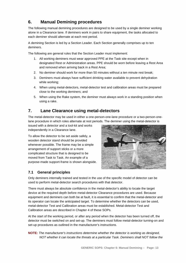
To allow the detector to be set aside safely, a wooden detector stand should be provided whenever possible. The frame may be a simple arrangement of support sticks or a more complicated structure that is designed to be moved from Task to Task. An example of a purpose-made support-frame is shown alongside.
7.1 General principles Only deminers internally trained and tested in the use of the specific model of detector can be used to perform metal-detector search procedures with that detector.
There must always be absolute confidence in the metal-detector’s ability to locate the target device at the required depth before metal-detector Clearance procedures are used. Because equipment and deminers can both be at fault, it is essential to confirm that the metal-detector and its operator can locate the anticipated target. To determine whether the detectors can be used, metal-detector Test and Calibration areas must be established. Metal-detector Test and Calibration areas are described in Chapter 4 of these SOPs.
At the start of the working period, or after any period when the detector has been turned off, the detector must be switched on and set-up. The deminers must follow metal-detector turning-on and set-up procedures as outlined in the manufacturer’s instructions.
NOTE: The manufacturer's instructions determine whether the detector is working as designed, NOT whether it can locate the threats at a particular Task. Deminers shall NOT follow the
GENERIC SOPS: Chapter 6: Manual Demining – Page: 13
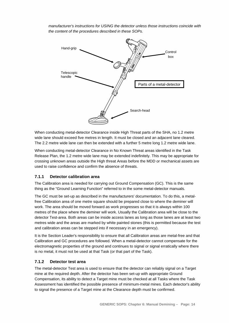
manufacturer's instructions for USING the detector unless those instructions coincide with the content of the procedures described in these SOPs.
Hand-grip
When conducting metal-detector Clearance inside High Threat parts of the SHA, no 1.2 metre wide lane should exceed five metres in length. It must be closed and an adjacent lane cleared. The 2.2 metre wide lane can then be extended with a further 5 metre long 1.2 metre wide lane.
When conducting metal-detector Clearance in No Known Threat areas identified in the Task Release Plan, the 1.2 metre wide lane may be extended indefinitely. This may be appropriate for crossing unknown areas outside the High threat Areas before the MDD or mechanical assets are used to raise confidence and confirm the absence of threats.
7.1.1 Detector calibration area The Calibration area is needed for carrying out Ground Compensation (GC). This is the same thing as the “Ground Learning Function” referred to in the some metal-detector manuals.
The GC must be set-up as described in the manufacturers' documentation. To do this, a metal-free Calibration area of one metre square should be prepared close to where the deminer will work. The area should be moved forward as work progresses so that it is always within 100 metres of the place where the deminer will work. Usually the Calibration area will be close to the detector Test-area. Both areas can be inside access lanes as long as those lanes are at least two metres wide and the areas are marked by white painted stones (this is permitted because the test and calibration areas can be stepped into if necessary in an emergency).
It is the Section Leader's responsibility to ensure that all Calibration areas are metal-free and that Calibration and GC procedures are followed. When a metal-detector cannot compensate for the electromagnetic properties of the ground and continues to signal or signal erratically where there is no metal, it must not be used at that Task (or that part of the Task).
7.1.2 Detector test area The metal-detector Test area is used to ensure that the detector can reliably signal on a Target mine at the required depth. After the detector has been set-up with appropriate Ground Compensation, its ability to detect a Target mine must be checked at all Tasks where the Task Assessment has identified the possible presence of minimum-metal mines. Each detector's ability to signal the presence of a Target mine at the Clearance depth must be confirmed.
Search-head
Control box
Telescopic handle
Parts of a metal-detector
GENERIC SOPS: Chapter 6: Manual Demining – Page: 14

The deminer must NOT use a metal-detector manufacturer's test piece as a reliable simulation of a real mine target. Target mines that accurately reflect the electromagnetic signature of the mine that is most difficult to locate at the Task must be used. This is usually a real mine that has been rendered safe. Target mines are described in Chapter 4, of these SOPs. Examples of how to make some common mines into Target mines are given in Chapter 10, Part 8 of these SOPs.
NOTE: A minimum-metal mine that has been rendered safe for use as a metal-detector target is NOT Free From Explosive (FFE) because the detonator is generally present. They must not be marked as FFE but as "Detector Targets". They should be transported and stored as "detonators". They should be clearly marked (painted red) to avoid any confusion.
The Platoon EOD Operative should provide and control all Target mines, ensuring that they are recovered when they are no longer required and stored in the Explosives storage area.
The target mines must be buried in metal-free Detector test areas close to where the deminers will work (usually within 100 metres). Each target mine should be concealed in a marked area measuring at least 0.5 metres on each side. The target mine must be buried so that the top of the mine is at the required Clearance depth at the Task. The photograph alongside shows the depth of a test mine being measured.
It is the Section Leader's responsibility to ensure that metal-detector Test areas are metal free before the target mine is placed and that target mines are placed at the required depth.
The detector Test area is often positioned alongside the detector Calibration area but need not be. Both areas must be clearly marked.
7.1.3 Using the detector Test and Calibration areas The deminer must set-up the detector in the Calibration area and then use it over the detector Test area to check that the detector signals on the test mine. If the metal-detector does not give a distinct signal over the test mine, the detector should be set-up (with GC) again and a second attempt made by a Section Leader. If there is any ambiguity about the signal, the Section Leader must repeat the test with other detectors. If the problem is repeated, the Section Leader must report that Clearing the area with metal-detectors is not appropriate and the Platoon Commander should ensure that the Task Release Plan is adjusted appropriately.
If the Section Leader can detect the test mine but the deminer cannot, the deminer must not be allowed to work with a metal-detector until he/she has been trained to use the detector again.
If the Section Leader cannot detect the test mine but can detect it with other detectors, the metal-detector must be withdrawn from service immediately.
Every time that a deminer leaves the working area (for rest breaks etc) the ability of the detector to signal in the Test area should be confirmed. Detector performance can change while it is being used. This may happen, for example, as a result of temperature variations, battery condition or general malfunction. If the detector does not signal on the target concealed in the Test area when the deminer leaves the working area, the area searched since the last check must be searched again. The second search can be conducted using a detector that does signal reliably in the Test area, or using other procedures.
7.1.4 Search-head movement The sideways movement of the search-head depends on its operating principle ("static" or "dynamic"). The search-head of a dynamic detector must be constantly moved over a target in
GENERIC SOPS: Chapter 6: Manual Demining – Page: 15

order to signal. The search-head of a static detector will continue to signal when held still over a target. Some models of detector can be switched between static and dynamic operation.
Whichever model of detector is used, the required rate of advance is one third (or less) of the search-head width when searching for minimum metal mines or one half of a search-head width when looking for mines with more metal inside. The search procedure is described in Part 7.3 of this Chapter. (This may be varied in BACS processes, but not in full Clearance processes).
7.2 Using the metal-detector This section provides a detailed description of the use of one particular model of metal-detector, the MineLab F3. This detector is a very good “all-rounder” able to be used anywhere in the world. It is probably the best detector for locating minimum metal mines at depth in electromagnetic soils, but it is not the simplest or most robust metal-detector available. When simpler and more robust detectors are capable of finding the mines reliably in the ground conditions at a task, they should be preferred.
The preferred secondary detector is one of the Ebinger (EBEX) 420 series. Over ten years, these have proven especially popular. Their lightness makes them easy to use vertically when kneeling, as shown in the photograph alongside, which can speed up fragment location. Whichever model of metal-detector is used, it is essential that the detector is used frequently to confirm the position of the metal during the signal investigation process.
7.2.1 Switching “mode” with the MineLab F3 The Control-box of the F3 has a coloured plastic end-cap that is changed to select different modes. By changing mode, users can reduce the sensitivity of the detector and allow it to be used for BACS without signalling on all small metal items.
While searching for mines, the black end-cap should always be used. When searching for large metal objects during BACs, the red end-cap can be used.
The end cap is removed by pressing in the centre at the same time as pulling the lower edge away – as shown in the photograph alongside.
Small electronic connectors inside the end-cap change the configuration of the detector. If no end-cap is fitted, the detector operates with the same sensitivity is with the black end-cap.
If other coloured end-caps are sourced, their use must be fully documented in an amendment to this SOP before they are issued.
7.2.2 Turning on and checking the detector The MineLab F3 detector must be prepared for use in the following manner:
1. Hold the F3 upside down and unlock the battery pack lid by twisting the battery-lock lever anti-clockwise a quarter of a turn. Pull the lid away from the battery pack.
The lid will stay attached by a tether to the battery pack.
2. Using the battery maps on the side of the battery pack and on the inside of the lid, insert four D cell batteries.
GENERIC SOPS: Chapter 6: Manual Demining – Page: 16

BatteryMap
BatteryPack
BatteryPack Lid
BatteryLockLever
3. Replace the battery pack lid and turn the battery lock lever clockwise a quarter of a turn. If the batteries are not inserted correctly, the F3 will not work when it is switched on.
NOTE: Only use NiCad or NiMh D cell rechargeable batteries with a capacity of at least 4000 mAH.
4. Unclip the search-head lock and position the search-head in line with the handle.
5. Extend the lowest part of the detector by at least 10cm.
The detector may not work properly unless it is extended by at least this amount.
6. Extend the telescopic handle to the length that
will be used.
7. Adjust the arm-rest and tighten the arm-strap as required.
8. Hold the detector with the search-head high in the air and slide on the on/off-switch towards the handgrip.
The detector runs through a series of internal self-tests that take 12 seconds. While this is happening, the detector makes four Start-up tones that rise in pitch.
9. When the Start-up checks are completed the detector makes a low steady low tone called the normal tone.
The normal tone will get louder if the search-head is left over electromagnetic ground for a long time, or if the search-head is twisted around in relation to the handle. If the normal tone ever gets louder, press the green Audio-reset button to return it to normal.
Interference from electrical motors, lights, power lines and other detectors may make the normal tone vary in pitch and volume. When this happens, press the Noise Cancel button to make the detector search for an operating frequency that will minimise the interference.
10. Wait half a minute after the normal tone has started, then move to the detector calibration area to perform a “ground balance” on the detector. Start by holding the search-head 15cm above the ground over the calibration area.
GENERIC SOPS: Chapter 6: Manual Demining – Page: 17

11. Press and hold down the green Ground Balance button the detector handle. Holding the button down, slowly lower the search-head to the ground, then slowly raise it again.
12. Slowly lower and raise the search head until the detector makes a short, high-pitched beep-beep noise. Then stop pressing the green Ground Balance button.
15cm
13. Test the detector using the detector test-piece. Hold the test-piece so that the metal part is AWAY from the search head. Slowly move the test-piece towards the centre of the coil until it lightly touches the surface then move it sideways off the coil.
A faint but clear change in volume and pitch should be heard.
14. The detector is ready to use in the detector Test area.
15. In the detector Test area, the search-head must be used over the concealed test-mine to confirm that the test-mine gives a distinct signal. This gives the deminer confidence and also allows the deminer to become familiar with the sound that the detector makes when the target mine is located at that depth.
7.2.3 MineLab F3 Search patterns The detector is a “static” detector, so the search-head does not have to be kept moving in order for the detector to signal when there is a target under it.
7.2.4 Pinpointing with the MineLab F3 Having detected a target and gained a rough idea about its size and location using the sweeping search procedure, the precise location of the target can be found using the F3’s “Edge Detection” technique.
To detect the edge of concealed metal, the search-head should be brought towards the target location from all angles as shown on the right.
As the search-head approaches the target, the normal tone will change, indicating that there is a target close by. When the normal tone changes, the deminer should note the position on the ground, move the search-head away, and approach the target from another angle.
This should be repeated until the deminer has a mental picture of the target area.
NOTE: After an initial detection, if the search-head is repeatedly swept over a small target, the signal may fade. If this happens, move the search-head away from the target and quickly press and release the green Ground Balance button. This will reset the tone and the detector should signal over the target again.
The signal marker should be placed at the nearest part of the signal to the base-stick.
GENERIC SOPS: Chapter 6: Manual Demining – Page: 18
When pinpointing using the edge-detection technique reveals an irregularly shaped target, it may be that there are more than one target close together as shown in the drawing below.
P0627 A
The variation in pitch of the detector signal as the search-head is passed over the top of the target(s) may allow an experienced operator to discriminate between the separate targets. This is because the detection noise varies with different metals.
NOTE: In all cases where an irregular perimeter is found, the deminer must expect that there may be small targets close to a larger target.
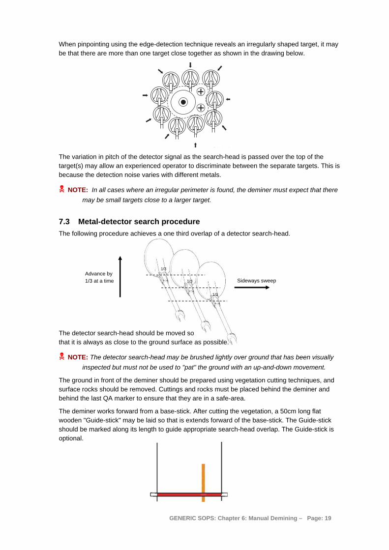
7.3 Metal-detector search procedure The following procedure achieves a one third overlap of a detector search-head.
1/3 Advance by 1/3 at a time 1/3
1/3
Sideways sweep
The detector search-head should be moved so that it is always as close to the ground surface as possible.
NOTE: The detector search-head may be brushed lightly over ground that has been visually inspected but must not be used to "pat" the ground with an up-and-down movement.
The ground in front of the deminer should be prepared using vegetation cutting techniques, and surface rocks should be removed. Cuttings and rocks must be placed behind the deminer and behind the last QA marker to ensure that they are in a safe-area.
The deminer works forward from a base-stick. After cutting the vegetation, a 50cm long flat wooden "Guide-stick" may be laid so that is extends forward of the base-stick. The Guide-stick should be marked along its length to guide appropriate search-head overlap. The Guide-stick is optional.
GENERIC SOPS: Chapter 6: Manual Demining – Page: 19

The preferred base-stick has 5 metre tapes attached to each end. The tapes are rolled out as work progresses. They are marked at every metre, providing a reminder to the deminer about placing side-marking. See Chapter 5, Part 2.1 in these SOPs.
The same search pattern must be used whether the deminer is standing or kneeling. The telescopic handle should be adjusted to an appropriate length before the detector is used in the detector calibration and test areas because changing the length of the telescopic handle can change the detector’s sensitivity.
The picture on the left shows a standing deminer with the handle of the MineLab F3 extended. This deminer is using a Guide-stick to ensure the correct search head overlap.
The picture below shows a kneeling deminer with a short-handled Ebinger 420 detector.
1. The search-head is placed in the middle of the base-stick, with at least one third of the search-head behind the base-stick. When using a raised base-stick, the search-head is placed under the base-stick. See Chapter 5, Part 2.1 of these SOPs.
2. The search-head is moved to the right and beyond the end of the base-stick. The overlap outside the lane must be at least 10cm. The search-head is constantly kept as close to the ground as possible without applying pressure to the ground.
GENERIC SOPS: Chapter 6: Manual Demining – Page: 20

3. The search-head is moved all the way to the left without advancing it and beyond the end of the base-stick. The overlap outside the lane must be at least 10cm.
4. The search-head is moved forward by a third of the search-head length or less, and swept to the right. If the detector signals, the sweeps are not interrupted.
5. Advancing by one third of a search-head length or less, the head is advanced until it is at least one-third over the end of the guide-stick (or 40cm in front of the deminer) and over the nominal side of the search area (overlap). If the detector signals, the deminer must remember the approximate position and keep searching.
6. The detector head is moved back over the search area in a reverse action. If the detector signals, the sweeps are not interrupted, but a mental map of the search area is made.
The deminer now knows how many signals are in the area and their approximate position. If two signals are close together, or are in a linear pattern (as is common with lengths of wire), the deminer knows this and so can pinpoint the closest signal (or the part of a signal that is closest).
7. If there are no signals in an area, the base-stick is moved forward to 10cm closer than the extent of the search. The deminer then removes the vegetation and rocks in front of the stick and starts the search process again.
If there are signals in the area, the deminer should first inspect the ground visually for surface metal and carefully remove any obvious metal by hand. Exposed wire or other items must not be pulled if parts are under the ground. After a visual inspection, the deminer should use a magnetic tool to try to remove metal that cannot be easily seen. The magnet should be brushed lightly over the ground surface to attract magnetic material on the surface.
After using the magnet, the area must be searched with the detector again as described in Steps 1-6 above.
8. After the area has been searched with the metal-detector, surface fragments removed and the search repeated, the deminer must pinpoint the closest signal to the base-stick and place a marker at that place.
If there are no metal readings, the deminer should move the base-stick forward to 10cm closer than the extent of the search. To ensure overlap, the base-stick should never be moved all the way to end of the area searched.
GENERIC SOPS: Chapter 6: Manual Demining – Page: 21

When a base-stick with marking tape attached is used, the deminer looks at the tapes to see whether any of the one metre marks on the tape are showing. If they are, the deminer must place side of lane marking. When a mark is very close to the base-stick, the marking may be left until it is moved forward again.
7.3.1 Pinpointing a detector reading The method of pinpointing varies with the metal-detector but will either involve using the search-head to approach the signal from all sides ("a" below as with the MineLab F3) or moving the search-head across the signal in "cross-hairs" ("b" below). When a small target is deeply buried, it may not be possible to pinpoint accurately, so the deminer should be cautious and place the marker slightly closer to the base-stick than the signal.
The marker must be placed at the nearest part of the signal to the deminer's base-stick.
NOTE: When marking mines with a central fuze mechanism, the marker often indicates the centre of the mine. When marking large metal-cased mines, the marker indicates the side of the mine nearest to the base-stick.
When the nearest signal has been pinpointed, the signal investigation procedure must be started.
7.4 Investigating a metal-detector signal using hand-tools When a metal-detector signal has been pinpointed and a signal marker placed at the nearest part of the reading, the deminer can begin a signal-investigation procedure. If at any point during the procedure the source of the metal-detector indication is found and it was not a mine or ERW, the deminer should stop the investigation and return to the metal-detector search procedure, checking the area where the metal was found to see if there are other indications. If a mine or ERW is located, the deminer should expose the side of the device closest to the base-stick and follow the actions detailed in Part 11 of this Chapter.
Hand-tools approved for use during signal excavation should meet the design requirements given in Chapter 2, Part 3.3 of these SOPs.
The picture above shows some of the approved blast resistant hand-tools. Any tool that is used in the ground during signal excavation should be blast-resistant. Tools designed for gardeners may only be used for vegetation cutting.
GENERIC SOPS: Chapter 6: Manual Demining – Page: 22

7.4.1 Magnets Strong magnets can be very useful in areas where metal-detector search is used and there is a lot of metal contamination in the ground. Magnets may be attached to tools such as the light rake or trowel, or can be held in the hand. They should be brushed over the ground surface without downward pressure.
The photograph below shows typical minefield scrap metal. Most of the metal has a ferrous content, so it is magnetic. The only item that is not magnetic is the ring-pull from a drink can.
7.4.2 Special tools for hard ground When ground is exceptionally hard, a signal investigation may be started using a two-handed digging tool to break up the ground surface at least 20cm from the nearest part of the indication (the distance from the indication must be more than half the diameter of the largest anticipated target at the Task). Digging down to the Clearance depth in a safe place gives the deminer a point from which to work forward towards the indication using other tools.
The deminer in the photograph above is using a two-handled tool to start the excavation well away from the metal-detector reading. The tool is made using blast-resistant material and its design includes a guard for the hand that would be closest to any blast.
GENERIC SOPS: Chapter 6: Manual Demining – Page: 23
7.4.3 Slicing tools When investigating a metal-detector investigation or conduction area-excavation, there are times when the use of a tool that slices away the face of the excavation without first prodding that ground for obstructions can be efficient and safe.
Prodding must be conducted as described in the procedures under Part 7.4.3 below unless none of the anticipated targets are movement sensitive and none have pressure plates extending to the edge of the mine.
Movement sensitive ERW includes some submunitions that must be excavated with the greatest caution.
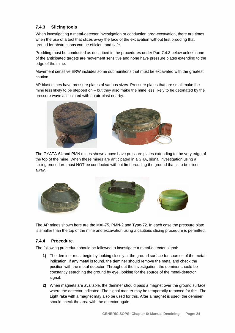
AP blast mines have pressure plates of various sizes. Pressure plates that are small make the mine less likely to be stepped on – but they also make the mine less likely to be detonated by the pressure wave associated with an air-blast nearby.
The GYATA-64 and PMN mines shown above have pressure plates extending to the very edge of the top of the mine. When these mines are anticipated in a SHA, signal investigation using a slicing procedure must NOT be conducted without first prodding the ground that is to be sliced away.
The AP mines shown here are the MAI-75, PMN-2 and Type-72. In each case the pressure plate is smaller than the top of the mine and excavation using a cautious slicing procedure is permitted.
7.4.4 Procedure The following procedure should be followed to investigate a metal-detector signal:
1) The deminer must begin by looking closely at the ground surface for sources of the metal-indication. If any metal is found, the deminer should remove the metal and check the position with the metal-detector. Throughout the investigation, the deminer should be constantly searching the ground by eye, looking for the source of the metal-detector signal.
2) When magnets are available, the deminer should pass a magnet over the ground surface where the detector indicated. The signal marker may be temporarily removed for this. The Light rake with a magnet may also be used for this. After a magnet is used, the deminer should check the area with the detector again.
GENERIC SOPS: Chapter 6: Manual Demining – Page: 24

3) An investigation should be started by prodding the ground at least 20cm back from the signal marker. In most ground, the prod will not penetrate more than a few centimetres. The deminer must not apply excessive pressure to make the prodder go more deeply into the ground. If the prodder will not penetrate 3cm, the deminer should use another approved tool to break the ground surface. Sometimes the ground has a crust with softer spoil underneath. Frequently the ground becomes harder as the investigation gets deeper, and the use of other tools may be required.
The ground should be prodded or broken-up over a width of excavation equal to the width of the anticipated threats at the site. If AP mines are expected, a width of 15cm is required. If AT mines are expected, a width of at least 30cm is required.
4) The ground that has been loosened with the prodder should then be removed with a trowel.
Whenever metal is found during the excavation, with the magnet or by eye, the deminer should check the position of the original indication with the metal-detector.
5) Steps 3 and 4 should be repeated as many times as necessary to create a sloping hole at least 15cm wide advancing towards the signal-marker. The depth of the hole should reach the required Clearance depth at the site BEFORE the marker is reached.
The side of the excavation closest to the marker is approximately vertical. This must be prodded from the bottom upward at a spacing of 2cm. The prodded earth can then be removed with the trowel. When the prodder meets an obstruction, the prodder should be used to feel for the sides of the obstruction and so estimate its size. The trowel should then be used with extreme caution to expose the obstruction.
In soft ground, it may be possible to insert the prodder a considerable length into the ground. The prodded ground can then be cut away with the trowel in complete confidence that there is nothing concealed within it. The ground cut away must never be more than the ground searched with the prodder.
GENERIC SOPS: Chapter 6: Manual Demining – Page: 25

For safety and to ensure an overlap, the deminer must never cut more away than 75% of the soil that has been prodded. The length prodded is NOT the distance ahead of the excavation face that can be safely removed with a trowel. The picture above shows a prodder inserted 8cms into the ground. Because of the angle of the prodder, the prodder has only reached 7cms into the unknown ground. In this example, if a deminer were to cut 8cm of soil away with the trowel he/she would press on the edge of a concealed PMN mine.
After prodding (bottom upwards) the face of the signal-investigation, the deminer should insert the prod a final time and grip the blade to record the depth before withdrawing it. He/she should then estimate three-quarters of the length and mark the ground ahead of the hole lightly with the prodder tip. The ground up to that mark can then be removed with the trowel safely.
Lightly tapping an obstruction with the prodder can sometimes provide feedback to confirm that the object is likely to be a mine. The deminer must expose any obstruction with extreme caution, regardless of the “feedback” from the prodder.
6) If no obstruction is found at the signal-marker, the deminer should check the position of the indication with the metal-detector. When the metal-detector continues to signal over the area, it may be appropriate to dig more deeply. The Section Leader should decide this based on the Task Risk Assessment and any pattern of mines that may be known. The Section Leader should consult the Platoon Commander over any uncertainty. Generally, when a mine is missing from an anticipated pattern and there is a metal-detector signal near where the mine was expected, the depth of excavation should be increased until the source of the signal is found.
When searching more deeply, the deminer should start excavating again, beginning further away from the indication and extending the slope of the hole so that any hidden device will still be approached from the side.
When a mine/device has been found and the parts facing the deminer have been gently exposed, the deminer should follow the actions detailed in Part 11 of this Chapter.
7.5 Investigating a metal-detector indication using rakes The REDS rakes can be used for signal investigation. The hand-tools approved for signal investigation must also be available, along with a plastic bucket in which to place contaminated ground. The use of the REDS rakes for Area Excavation is covered in Part 9 of this Chapter.
The light rake can be fitted with a magnet to help remove metal-clutter.
GENERIC SOPS: Chapter 6: Manual Demining – Page: 26

The photograph on the left shows a light rake with a magnet attached. The photograph on the right shows a deminer removing magnetic pieces from the magnet after raking the ground.
The scratching action of the rake loosens fragments in the soil surface and often means that the deminer finds the metal that made the metal-detector signal.
NOTE: The light rake must be tested against the AP blast mines that may be present. Testing the light rake involves using the rake to expose a rendered-safe test-mine. The initiation mechanism of the test-mine must be intact and the High Explosive removed. If the light rake initiates the fuze mechanism in the test-mine, it fails the test and cannot be used at Tasks where that mine is anticipated. Anti-personnel mines that have passed previous tests include the PkMk2/4, Type 72, PMA-3 and PRB M35.
The use of REDS rakes to investigate metal-detector signals can be very fast when mines are relatively close to the surface or when the source of a detector reading was a ferrous fragment close to the surface. In soft ground, the time saving over using other hand-tools to make the investigation can be significant.
Variations in REDS rake design should be tested. Heavy rake heads should be made using E304 Stainless Steel. Light rake heads may be made from plastic or sprung steel.
The REDS light rake (with or without a magnetic attachment) and the REDS heavy rake can be used to investigate metal-detector readings or for area-excavation.
Before starting the REDS detector investigation procedure, an area behind the deminer must be prepared to place the rakes and the metal-detector so that the deminer can change tool quickly.
7.5.1 Procedure When a detector signal has been pinpointed, the deminer can begin a signal-investigation procedure with rakes. The following procedure should be followed:
1. Remove the signal marker and make a mental note of its position.
2. In a standing position, and holding the handle well away from the rake-head, use the light rake over the area where the metal-detector signalled. The rake tines scratch the ground surface and can help to loosen fragments just below the ground surface, which are then attracted to the magnet. Soil collected by the brushing of the rake should be moved back to the base-stick.
The area raked will usually extend from 20cm beyond the metal-detector reading to the base-stick and be the width of the light rake head.
GENERIC SOPS: Chapter 6: Manual Demining – Page: 27

3. Look closely for exposed metal. When the magnetic light rake is used, the magnet may have picked up the metal. Use a hand-held magnet if necessary. If metal is found, the deminer should use the metal-detector to check the position of the indication. If the indication has gone, the investigation has been completed and the deminer should return to the metal-detector search procedure.
4. The area must be searched with the metal-detector again. This must be done whether or not metal fragments have been found because the action of the rake may have moved the signals around. Not all metal is magnetic, and non-magnetic metal may have been moved by the rake.
5. Use the light rake to move soil from the area of the indication back to the base-stick. Continue until the light rake becomes ineffective. When roots are uncovered, they should be cut with pruners.
6. Check with the metal-detector to find out whether the signal has moved.
7. If the signal has moved, move the loosened earth into the plastic bucket and check with the metal-detector again.
8. If the metal-detector signal has not moved, use the heavy rake. Hold the rake handle as far as possible from the rake head. Place the heavy rake on the ground surface beyond the metal-detector reading in a place where the metal-detector did not signal when the area was searched.
NOTE: The metal-detector search procedure usually means that an area beyond a signal position has been searched with the detector. When it has not, the deminer should ensure that the area closest is clear, then advance the base-stick so that he/she can safely sweep the search-head beyond the area under investigation before using the heavy rake.
9. Drag the heavy rake towards the base-stick without downward pressure. Repeat this across the area where the metal-detector signalled until the soil is loose. Place the heavy rake in the safe-area.
10. Use the light rake to move the loosened soil back to the base-stick.
11. Return to Step 3 and check with the metal-detector to find out whether the metal has moved. Repeat Steps 3 to 10 until the detection depth has been reached or until the reason for the metal-detector signal has been found.
When a device is close to the surface or in loose soil, the light rake will expose the top of it. When this happens, the movement of the rake tines over the device can make an obvious scratching noise. In soft ground the heavy rake may expose or lift a mine or ERW to the surface.
When a mine or ERW is found, the deminer should expose the parts facing the base-stick using approved hand-tools when necessary, then follow the instructions in Part 11 of this Chapter.
NOTE: The heavy rake must not be placed on the ground directly above a metal-detector indication or on ground that has not been searched using the metal-detector.
If the ground becomes very hard as the depth increases, the deminer should be permitted to use the metal-detector to reposition the signal-marker and start an alternative investigation procedure using approved hand-tools.
GENERIC SOPS: Chapter 6: Manual Demining – Page: 28

8. Area Excavation using hand-tools In area-excavation, the whole ground surface is searched by moving it. A base-trench is used and the base-trench moves forward as work progresses in the same way that a base-stick moves forward during metal-detector Clearance. When conducted properly, area-excavation gives total confidence that the area searched contains no mines or ERW to the Clearance depth. The method is slow and hard work, but absolutely thorough.
Area excavation is performed using a one-person one-lane procedure. When a mine or ERW is found, the deminer withdraws, informs his/her Section Leader and either waits until the EOD Operative has dealt with the device or starts a new lane. When the EOD Operative is not immediately available, the Section Leader should always instruct the deminer to start a new lane.
The area-excavation procedure is hard work, so, depending on weather and ground conditions, deminers should work in their lanes for a maximum of 30 minutes between rest breaks.
The deminer must start by making a “base-trench” within the safe-lane at the start of the Clearance lane. The “base-trench” moves forward into the SHA as the lane progresses. The first base-trench is always inside the safe-area, 120cm from side to side, and 10 - 20 cm from front to back. Its depth must be the required Clearance depth at the Task. As the base-trench is advanced, the sides of the lane are marked using hazardous-area sticks or stones on both sides at every metre.
Tools issued may include:
• Tripwire feeler • Grass cutting tools • Root cutting tools (pruners) • A handsaw • A hammer (for placing marking pickets) • Wire-cutters • Blast resistant ground engaging tools (see Part 7.4 of this Chapter). • A mattock to dig the first base-trench inside the safe-area.
NOTE: Mattocks must NEVER be used inside the SHA.
As a deminer progresses, all tools that are not being used should be kept behind the deminer and on one side of the working lane.
Tools used to slice away the ground may be used as described in Part 7.4.2 of this Chapter when the anticipated mines do not have pressure plates extending to the edges of the mine.
GENERIC SOPS: Chapter 6: Manual Demining – Page: 29

GENERIC SOPS: Chapter 6: Manual Demining – Page: 30
8.1 Procedure Follow the four steps shown below. They illustrate Clearance in a lane, but the same principle applies when starting from a base-line.
Step 1
Visual check, Undergrowth removal
120cm
Step 2
Base-trench
The first base-trench is entirely inside the safe-area. It must be 120cm
wide and as deep as the required Clearance depth
Cleared of vegetation and obstructions
30 – 50cm
safe-area
Slice away ¾ of the area that has been prodded and move the soil to the near side of the
base-trench.
Ensure that the far side of the base-trench remains as deep
as the required Clearance depth.
Step 4 Step 3
Prod from the bottom upwards and at 2cm
intervals across the face of the excavation.
When steps three and four have been completed across the entire face of the base-trench, the prodding in Step 3 starts again.
When mines with pressure plates extending to the edges of the mine are expected, the safety of the procedure relies heavily on prodding the face of the excavation before cutting it away. Prodding should begin at the bottom of the far side of the trench. The face of the trench should be prodded at 2cm intervals upwards and sideways.

Face of the base-trench
Base-trench
If an obstruction is encountered, prod to both sides of the obstruction. If the obstruction continues, soil must be cautiously removed up the obstruction to check whether it is a mine or other ERW.
In soft ground, it may be possible to insert the prodder a considerable length into the ground. The prodded ground can then be cut away with the trowel in complete confidence that there is nothing concealed within it. The ground cut away must never be more than the ground searched with the prod. For safety and to ensure an overlap, the deminer must never cut more away than 75% of the soil that has been prodded. The length prodded is NOT the distance ahead of the excavation face that can be safely removed with a trowel.
75%
The picture above shows a prodder inserted 8cms into the ground. Because of the angle of the prodder, the prodder has only reached 7cms forward into the unknown ground. In this example, if a deminer were to cut 8cm of soil away with the trowel he/she would press on the edge of a concealed PMN mine as he/she did so.
After prodding (bottom upwards) the face of the signal-investigation, the deminer should insert the prod a final time and grip the blade to record the depth before withdrawing it. He/she should then estimate three-quarters of the length and mark the ground ahead of the hole lightly with the prodder tip. The ground up to that mark can then be cut away with the trowel safely.
If a mine or ERW is discovered, the deminer must tell the Section Leader and withdraw from the lane until the EOD Operative has assessed the situation and dealt with the device. Work in the lane must not continue until the mine or ERW has been removed or destroyed. Generally the deminer should start another lane and continue working.
GENERIC SOPS: Chapter 6: Manual Demining – Page: 31

9. Area Excavation using rakes When the Task Risk Assessment has NOT identified a threat from especially sensitive devices, tripwires or vertical fuzes (as are commonly used with fragmentation or AG mines), the Rake Excavation and Detection system (REDS) can be used. The vegetation in the area to be raked must always be cut before rakes are used. Because the use of mechanical demining systems generally removes all vegetation and loosens the ground, the REDS system can be especially useful after mechanical ground processing.
REDS is performed using either a one-person one-lane procedure or a two-man one-lane procedure in which roles alternate at rest periods. The raking deminer is issued with rakes and a tool kit and works independently in a lane. His/her partner rests at the appropriate safety-distance while the raking deminer works. When a mine is found, the raking deminer must close the lane and inform the Section Leader. He/she then either waits until the EOD Operative has dealt with the device or starts a new lane.
The raking procedure is hard work, so, depending on weather and ground conditions, deminers should work in their lanes for a maximum of 30 minutes between rest breaks or between alternating with their resting partner.
All working deminers must wear frontal blast protection. As a further safety feature to ensure the deminer’s distance from any initiation, all deminers must work in a standing position when using the rakes, but they may kneel or squat when using other tools.
The raking deminer must start by making a “base-trench” within the safe-lane at the start of a Clearance lane. The “base-trench” moves forward into the suspect area in the same way as a base-stick does in metal-detector procedures as the lane progresses. The first base-trench is always inside the safe-area, 120cm from side to side, and 10- 20 cm from front to back. Its depth must be the required Clearance depth at the Task. As the base-trench is advanced, the sides of the lane are marked by leaving narrow trenches. A hazardous area picket or painted stone should be placed in the side trenches on both sides at every metre.
Heavy- and light rakes are used. Other tools issued may include: • tripwire feeler; • grass cutting tools; • root cutting tools (pruners); • a handsaw; • a hammer (for placing marking stakes); • wire-cutters; and • a trowel.
As a deminer progresses, all tools that are not being used should be kept behind the deminer and on one side of the working lane.
9.1 Procedure To start a lane, a base-trench is dug to the required Clearance depth, 120cm wide and at least 20cm from front to back in a known safe-area at the start of the lane. The distance front to back of the base-trench may be varied according to ground conditions but should never exceed 50cm. When the first base-trench is made, it should always be entirely inside the safe-area. Because it is inside a safe-area, it can be dug with other tools than the rakes.
The soil from the initial excavation should be moved out of the base-trench and to the rear until the process is under way.
The area (up to) 50cm forward of the base-trench is visually checked and cleared of vegetation and loose stones. The light rake is then used to move all soil in the 20-50cm by 120cm area to the
GENERIC SOPS: Chapter 6: Manual Demining – Page: 32

front. The loosened spoil is brushed towards the back of the base-trench. The light rake is used as the main excavation tool and, when possible, is used to excavate to the required depth, exposing any mines/devices in the process. When the rake comes into contact with a mine, the sound of it scratching the device is often heard, alerting the deminer to the presence of the mine before it is visible.
The heavy rake should be used only when the light rake becomes ineffective. The heavy rake scratches the ground, loosening it so that the light rake can be effective again. The head of the heavy rake is placed to the front of the base-trench and pulled back towards the deminer. The rake tines then plough back through the soil to the rear of the area being Cleared. The deminer must not hack at the ground with the heavy rake.
The heavy rake ploughing action is repeated across the width of the base-trench. The deminer may change between using the light and heavy rake several times until he/she is able to excavate to the required depth with the light rake.
Water may be used to soften the ground or damp-down dust if required.
When a mine or ERW is discovered, it should be exposed using an approved hand-tool. When the device can be clearly seen, the deminer must close the lane and alert the Section Leader who will inform the EOD Operative. Work in the lane must not continue until the mine or ERW has been removed or destroyed. Generally the deminer should start another lane and continue working.
The rakes are used as shown above and below (the deminers are wearing blast goggles).
Found mine
marker
Side of lane trenches
The photographs show deminers using rakes in Mozambique. The method was found to be safer than some others methods of excavation. The deminer’s head is a long way from any accidental detonation so the risk of severe injury is low as long as basic PPE is worn.
GENERIC SOPS: Chapter 6: Manual Demining – Page: 33
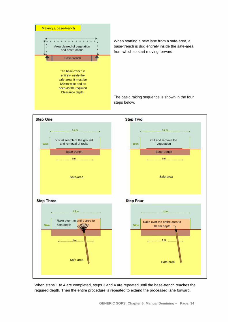
Making a base-trench
When starting a new lane from a safe-area, a base-trench is dug entirely inside the safe-area from which to start moving forward.
Area cleared of vegetation and obstructions
Base-trench
The base-trench is entirely inside the
safe-area. It must be 120cm wide and as
deep as the required Clearance depth.
The basic raking sequence is shown in the four steps below.
Visual search of the ground and removal of rocks
Base-trench
Cut and remove the vegetation
Base-trench
Rake over the entire area to 5cm depth
Rake over the entire area to 10 cm depth
Safe-area Safe-area
Safe-area Safe-area
When steps 1 to 4 are completed, steps 3 and 4 are repeated until the base-trench reaches the required depth. Then the entire procedure is repeated to extend the processed lane forward.
GENERIC SOPS: Chapter 6: Manual Demining – Page: 34

As the base-trench at the front of the lane moves forward, side-trenches to the full excavation depth are left at the sides of the lane in the area marked as “Overlap”. These side-trenches mean that the internal QA can ensure that the required depth has been consistently maintained.
Each deminer's Section Leader must use QA markers to show the extent of the lane to which the depth of the side trenches has been checked, and the side-trenches must be maintained until this has occurred. The Platoon Commander should periodically QA the work of the Section Leaders, checking that they are measuring the depth of all lanes regularly and that depth has genuinely been maintained.
Internal QA is part of the system. External QA must be made during Clearance if it is to be made in the same way. Post Clearance sampling (using rakes) may also be used for external QC.
When conducting REDS in a High Threat area, no 1.2 metre wide lane will normally exceed five metres in length. The lane will be closed and an adjacent lane cut. When the second lane reaches five metres, it can continue a further five metres before being closed and the deminer returns to extend the first lane.
When conducting REDS in areas in which No Known Threat has been identified in the Task Risk Assessment, the 1.2 metre wide lane may be extended beyond 5 metres in length. This may be appropriate for crossing No Known Threat areas before MDD or mechanical assets are used to raise confidence and confirm the absence of threats.
10. Using water to soften ground Water may be used to soften the ground or damp-down dust when necessary. A bucket or hose delivery system may be used to transport the water to end of the lane where the water should be splashed over the required area. All safety requirements at the Task should be observed during the watering process with working-distances maintained and PPE worn.
The deminer must close the lane and work in another lane while the water is allowed to soak into the ground. No signal investigation or excavation should be conducted until the surface water has gone.
When a bowser is available, water should be applied the day before the area is Cleared.
A dedicated bowser that is narrow enough to be driven along two metre wide lanes is ideal. The example shown in the photograph is both low-cost and versatile.
11. Action on locating a mine or ERW When the EOD Operative determines that it is safe to do so, mines and ERW may be moved for destruction outside the minefield. Damaged or unstable devices should be destroyed in-situ.
On locating a mine or ERW during any procedure, deminers should expose enough of the device to be sure that it is a mine or ERW and then close the lane. The deminer must inform his/her Section Leader who will inform the Platoon Commander. The Platoon Commander will instruct an
GENERIC SOPS: Chapter 6: Manual Demining – Page: 35

EOD Operative to deal with the device. If there is a delay dealing with the discovered device, the Section Leader must instruct the deminer to start work in another area. The deminer should not return to the lane until the device has been removed or destroyed.
The approved render safe procedures for some mines are documented in Chapter 10 of these SOPs. Some devices may be cautiously moved without rendering them safe.
NOTE: Mines or devices that are damaged or cannot be identified should not be moved.
11.1 Pulling procedure The pulling procedure must be conducted by one-person who should be an EOD Operative. The EOD Operative must presume that a detonation may occur. The pictures below show a set of pulling tools and the way that they are used.
Fulcrum, line and hooks used to turn devices over from a
distance. Pulling equipment may vary but the illustration shows the principle involved.
Pulling is conducted using the following procedure:
1. All people not involved in the pulling operation must be withdrawn to a safe-area. 2. Sentries must be posted to prevent people/livestock entering the area when necessary. 3. A pulling line must be rolled out from a safe point to the mine or ERW. The line must be in
place before the hook is put under the mine or ERW. The length of the line should equal the safety distance for the mine or ERW except when the EOD Operator can take adequate cover closer.
4. A fulcrum device may be used to make it easier to turn the device over. 5. When the line is prepared, the EOD Operative should attach the line to the device, usually
by pushing a hook under the far-side.
6. The EOD Operative must then confirm that the area is clear of people before returning to the safe point from which he/she will pull. Before pulling he/she must inform the Platoon Commander that he/she is about to pull (usually by radio).
7. The line should then be pulled in a slow, continuous movement until the mine or ERW has turned over or moved a minimum of two metres.
8. When the device does not detonate, the EOD Operative must wait a minimum of one minute before approaching it. The wait time should be extended if there is any concern about the condition of the device being pulled.
9. The EOD Operative should move the device to the place where it will be destroyed and place an appropriate marker where it was found.
GENERIC SOPS: Chapter 6: Manual Demining – Page: 36

10. The Platoon Commander must ensure that the original position of the mine or ERW is searched for any devices that were beneath it before it was pulled.
NOTE: The pulling procedure is not normally necessary for mines that have no anti-disturbance feature. Exceptions occur when any mine is in a condition that causes concern.
12. Removal of vegetation Whenever there is significant vegetation, the use of mechanical assets to cut the vegetation in front of manual demining should be considered. Whenever the Task Assessment indicates both the presence of vegetation and active tripwire activated devices, mechanical assets should be used to remove the vegetation whenever possible.
When mechanical assets are used to cut vegetation, minimum ground disturbance is necessary. Cut vegetation that is lying on the ground may be removed using a light rake as the follow-up work progresses as long as intact tripwires or active tilt-operated fuzes are not anticipated in the area.
12.1 Approved vegetation cutting tools A range of approved hand-tools can be used for the manual removal of vegetation. The hand-held petrol-driven Strimmer may also be used. There are restrictions on the way in which each tool can be used and the places in which their use is appropriate.
The tools generally approved for vegetation removal are listed below. It is the responsibility of the Programme Manager to ensure that deminers are always issued with appropriate tools for the task and have access to strong "gardening" gloves.
A: Shears; B: Secateurs (pruners); C: Sickle (hook); D: Saw (one-handed); E: Wire-cutters; F: Light rake; G: Petrol-driven Strimmer (long-handled); H: Tripwire feeler.
Deminers do not have to wear "gardening" gloves but they must be available whenever vegetation includes thorns, is sharp, or has stinging or skin-irritant properties. The gloves protect against the cuts and scratches that can occur during vegetation cutting.
NOTE: All tools can be used in a dangerous way, but some are hard to use in a safe way at any time. The following tools may NOT be used in any area that has not yet been declared safe (or presumed safe): machete; scythe; chainsaw; axe/hatchet. This is because the user cannot reliably control the tool (or the vegetation it cuts). These tools may be used in safe-areas, but should never be inside the SHA/CHA during demining.
The petrol-driven Strimmer and light rake may NOT be used in an area where the Task Assessment indicates the presence of functional tripwire initiated mines or other touch-sensitive devices on the ground-surface.
When using shears, sickle or saw, the blade(s) must not be pushed into the vegetation beyond the area that has been visually checked, or through which fingers have not passed feeling for obstructions.
When using a sickle (hook), the stem(s) to be cut should be gripped in one hand and cut carefully using the tool with the other hand. The tool must not be swung at the vegetation in a scything action.
GENERIC SOPS: Chapter 6: Manual Demining – Page: 37
When using a petrol-driven Strimmer the operator should wear frontal leg protection unless the design of the Strimmer removes all chance of a broken blade being thrown back towards the operator. The operator must always ensure that the cutting blade does not touch the ground. The operator must always ensure that his/her feet never leave the safe-area.
When using a light rake to collect vegetation cuttings, the user must always work in a standing position and hold the handle so that he/she is as far as possible from the head of the rake.
All tools should be in good condition with appropriately sharp blades. It is the responsibility of the Platoon Supervisor to ensure that sharpening stones and files are available in the rest area and for use during tool maintenance in the afternoons.
12.2 Manual cutting of vegetation Vegetation must be cut during manual Clearance, BAC and BACS procedures and in front of MDD. Because the vegetation will vary and may not cover the whole area in front, the process is described in terms of principles that must always be followed rather than as a step by step process.
The manual removal of vegetation must be conducted in a controlled and deliberate manner, avoiding any disturbance of vegetation outside the width of the lane and the safety overlap. The following rules must be applied:
1. Before and during the cutting, the deminer must make repeated visual checks for any item that has become visible.
2. Generally, trees or bushes with a trunk diameter of up to 10cm should be removed during manual demining.
3. Grass is cut 15cm above ground level to ensure that surface devices would be seen before ground level is reached. The height of the first cut should be increased if the Task Assessment suggests that large items may be on or above the ground surface.
4. When the deminer is confident that the tool will not strike any devices, the deminer should cut the vegetation close to the ground surface. Because stem thickness often increases near the ground, the deminer should use secateurs (pruners) when necessary.
5. When metal-detectors will be used, the vegetation should be cut very close to the ground. This allows the detector search-head to move close to the ground, so maximising the depth of search.
6. Undergrowth must always be cut. It must not be torn or broken.
7. The deminer’s feet must never leave the safe-area while cutting and removing vegetation. This usually limits the area in front of a deminer that can be cut to between 30 and 50cm from the base-line.
8. When vegetation is so tall that it might fall outside the lane when cut, it should be cut in lengths that allow the deminer to hold it and easily remove the cuttings to the safe-area.
9. When vegetation is unlikely to fall outside the working area, the deminer should work on his/her knees or crouching.
10. When using a one-handed cutting tool, the deminer should use one hand to hold the vegetation while the other uses the tool to cut it. When using shears, the deminer should move the cuttings to the safe-area as he/she works.
11. While cutting vegetation, the deminer should look for any indication of devices. This may include areas where no vegetation is growing but which can be seen more clearly because other vegetation has been removed.
GENERIC SOPS: Chapter 6: Manual Demining – Page: 38

12. Any cut vegetation in the Clearance area should be removed by hand or by using a light rake. The use of the light rake will depend on the hazards identified in the Task Assessment and must be approved by the Platoon Supervisor.
13. Cuttings should be stacked outside the lane for later disposal. Cuttings must always be stacked so that they do not obstruct emergency access to the working areas. The Section Leader should allocate an area for the deminer to place his/her cuttings and ensure that the cuttings are later moved and destroyed.
14. Destroying cut vegetation by burning must be conducted in a controlled manner inside a safe-area when no work in the SHA/CHA is happening. When burning is not appropriate, cut vegetation should be stacked in a safe-area where it causes no obstruction.
Devices that are located during vegetation removal should be left where they are until the ground up to them has been Cleared. The deminer must notify the Section Leader if any unexpected obstructions, such as barbed wire, ditches or large rocks, become visible as a result of vegetation removal.
12.3 Using a petrol-driven Strimmer The vegetation Strimmers (also called Brush-cutters) are commercial items developed for use in agriculture and municipal maintenance tasks. Proven in Humanitarian Demining in many countries, the tool provides a rapid and effective means of cutting grasses and thin-stemmed vegetation in areas where there is no tripwire or tilt-fuzed mine threat. Variations may be made to the tool to improve efficiency.
The photograph shows a Strimmer being used in demining.
The petrol-driven Strimmer may only be used by a deminer who has been internally trained and tested in its use. Usually the same person is responsible for its maintenance and for the correct storage of its spare parts and consumables.
GENERIC SOPS: Chapter 6: Manual Demining – Page: 39
The cutter is usually made using shaped metal with two or three blades.
The engine is carried on the deminer’s back.
Petrol-driven Strimmer (Usually with a 2-stroke engine)
The shaft of the Strimmer should be 1.5 metres from the handle to the cutting head, or longer.

The Strimmer may be used to cut inside the SHA/CHA along the sides of safe-areas. The width of the cut is usually around a metre, depending on obstructions. This can be especially useful when using lateral lanes in manual or MDD demining procedures.
Before Strimmer use, the Platoon Commander must ensure that an appropriate means of communication is in place. The noise of the machine prevents voice communication being adequate, so the Strimmer operator will usually have a VHF radio and may have an ear-piece. When necessary, a simple flag-system can be used and the Section Leader controlling the Strimmer operator must carry the relevant flag(s).
Detailed control of the Strimmer varies with each design. However, the following constraints apply whatever model of Strimmer is used:
1) The Strimmer operator should not put the moving cutting head in or over the uncleared area until all other staff are at the approved working-distance.
2) The Strimmer operator must wear frontal PPE, and should also wear frontal leg protection when the design of the tool makes this desirable.
3) The Strimmer operator must take all care to keep his/her feet inside the safe-area at all times.
4) The Strimmer operator should not allow the cutting head of the tool to strike the ground at any time.
5) The Strimmer operator must not move around in the safe-area with the cutter spinning.
6) No other person should approach closer than the working distance while the Strimmer is cutting vegetation (including supervisors).
Because a Strimmer must not be used in areas where surface fuzes, intact tripwires, or touch-sensitive devices are anticipated, vegetation cut with a Strimmer may be raked into a safe-area using light rakes.
12.4 Burning-off vegetation Burning-off vegetation can be done in the right conditions. These conditions are:
a) The Task Release Plan does not include the use of MDDs for at least seven days after the burning.
b) The Task Assessment has not identified plastic-cased mines on the ground surface. c) A broad (usually at least two metres wide) fire-break can be made on all sides of the area
to be burned. This is usually best achieved using a mechanical asset. d) The vegetation must be low and dry. Generally, dense or green vegetation should not be
burned-off because it will not burn well. e) Essential area-marking must be either already fire-resistant or replaced with fire-resistant
markers, such as painted stones and metal pickets. f) There is no expectation of high winds.
Controlled burnings are subject to the following additional constraints: 1) No demining work should be conducted within the working-distance for the area to be
burned or in any area where smoke drifts. 2) Sentries should be posted to prevent people or livestock entering the area during a
controlled burning whenever necessary.
GENERIC SOPS: Chapter 6: Manual Demining – Page: 40

13. Removing obstacles Common obstacles are:
• Rocks; • Barbed wire; • Fences; • Vehicle wrecks; • Ditches/trenches; • Abandoned or destroyed buildings; and • Fallen trees.
13.1 Rocks Some areas are littered with rocks of various sizes. In other places, piles of rocks and low-walls of rocks are found. All these impede demining. If there are many rocks, the use of mechanical demining assets that process the ground can be unwise because the rocks will cause a high level of wear to the machine and can prevent the machine processing the ground to a constant depth.
When using manual demining procedures, surface rocks that are small enough to be easily lifted should be removed. The deminer may reach in front by 30-50cm to lift the rocks. Rocks that are too large to be removed, or that resist lifting because they are partly buried, should be left in place until cleared around. Removed rocks should be transferred to an area behind the deminer that has been subjected to internal QA. They should be moved out of the lane before continuing to search.
When larger rocks have been cleared around so that the deminer can stand beside the rock, the deminer may try to move it again. This is because the rock may impede easy access in the lane and should be removed when possible. If the rock is moved, the area beneath it must be searched to ensure that no devices are present. If the rock cannot be easily moved, it should be left unless there is reason to believe that devices were placed beneath large rocks.
When piles or walls of rocks are encountered, the Task Release Plan should allow for the lanes to be diverted around the obstruction. When the area around the obstruction(s) has been cleared, the Task Supervisor must re-evaluate the Task Assessment and decide whether the piles must be moved and searched. When MDD assets are available, it may be appropriate to use them to search the piles of rocks.
If the rock obstruction must be moved, appropriate Mechanical assets may be used to assist.
13.2 Fences and wire Some minefields were originally fenced with strands or coils of barbed wire. In other areas, security and agricultural fences may be inside the area to be cleared. All broken fences should be removed and the area beneath them searched. Intact fences may be left unless their presence restricts the use of mechanical assets or prevents necessary access. When the area around an intact fence requires full Clearance, MDD may be used. If the metal-detector and the operator are capable of searching close to the fence reliably, metal-detectors may be used. When MDDs and metal-detectors are unavailable or inappropriate, the area around the fence must be excavated using area excavation techniques.
Wire obstructions can be cut cautiously using efficient wire-cutters. The wire must then be removed in sections and placed in a metal-collection area. The Platoon Commander may order that entanglements or buried wires are pulled using manual or mechanical means. Generally, the area surrounding the wire should have been searched first.
GENERIC SOPS: Chapter 6: Manual Demining – Page: 41

13.3 Vehicle wrecks When wrecked vehicles are found in the SHA, it must not be presumed that ground beneath the vehicle is safe. The remains of wrecked civilian vehicles should be pulled onto a known safe-area using mechanical assets.
Wrecked military vehicles should only be approached over ground that has been searched. They must be individually assessed by an EOD Operative who must presume that:
• there may be booby traps in and around the wreck; • there may be ammunition in and around the wreck; • there may be mines surrounding the wreck; and • there may be mines between the wreck and any nearby route.
13.4 Ditches/trenches If a ditch with collapsed sides is suspected of containing mines, it is possible that the mines will have become deeply buried. In these places, mechanical assets may be used to dig out the ditch and sift the spoil removed. The need for this will be determined on a case-by-case basis by the Task Supervisor. The use of a mechanical excavator is covered in Chapter 7.
In the photograph below, the trench has not collapsed but local people have moved barbed wire and mines into the trench so that they can move livestock in safety. The trench was cleared slowly by hand because there were also corpses in the trench and the local villagers thought that it would be disrespectful to dig the trench out with an excavator. The Task Supervisor must decide the best method to use on a case-by-case basis and should always listen to the desires of local people.
13.5 Abandoned or destroyed buildings If the building has been used by people and animals, the risk of booby trapping may be low. When a building has been destroyed in battle, there is a high chance that there may be UXO in and around the building.
GENERIC SOPS: Chapter 6: Manual Demining – Page: 42
NOTE: Buildings that still have window and door frames, roofing or plumbing fittings must be approached with great caution. In many countries, useful parts of buildings are scavenged. When useful parts are left in place, presume there is a reason for it. Consult the local population about the threat.
If the building is known to have been booby trapped, the time since the devices were placed may be relevant. Battery operated or improvised devices usually have a short operational life but may still be dangerous.
When manual Clearance must be conducted, lanes must be marked using painted stones. When there is rubble inside the building, the deminers must be issued with strong buckets to move the rubble outside. Intact walls may provide protection and allow a reduction in working-distances between deminers. Material on the floor must be removed until the search has reached the original floor level. Metal-detectors can be used in some areas but there may be a lot of scrap metal among the debris. Excavation using rakes or hand-tools may be more appropriate in some parts of the building.
The most efficient method of searching a building where booby traps are not expected is to use appropriately trained MDD.
When an abandoned building is not needed by the end-user and is believed to be booby trapped, it may be carefully dismantled using mechanical assets. Parts should be lifted into a marked safe-area and searched as work progresses. As with all mechanical processes, manual deminers may not approach the machine while it is working and approved area marking must be used.
Safe access around the building must be Cleared in a two metre wide safe-lane. After a safe-access route has been Cleared, the building must be inspected from the outside looking for visible devices or booby traps. When buildings have more than one room, the Section Leader must make a sketch map of the rooms inside the building.
The Task Supervisor must ensure that an appropriate plan is made for the clearance of any building with several rooms. This plan must include a demining sequence that allows for the following:
1. All access corridors must be Cleared before any rooms are entered.
2. Only one deminer is allowed into any room at one time, unless the floor area is big enough to allow working-distances to be applied. In small rooms, the deminers should work with two walls between them when possible.
3. A one-metre lane should be cleared into each room from the door to the far wall. Using this lane as a base-line, clearance lanes should be made at right angles to the base-line.
The Section Leader must supervise the deminer and always be aware of his/her progress. When visual contact may not be possible, the deminers must have radios and report progress regularly.
When access has been made to the inside of the building, the deminers should be withdrawn and an EOD Operative should check for possible booby traps. The EOD Operative should not move outside the Cleared access lanes. He should inform the Section Leader about possible booby traps and the Section leader must instruct the relevant deminer to stop as soon as access to the possible booby trap has been gained. The deminers will then withdraw and the EOD Operative will deal with the device appropriately.
Each room must be searched using the following procedure: 1. Check the area in front of the base-stick visually and feel for tripwires when appropriate.
2. Carefully cut and remove any vegetation.
GENERIC SOPS: Chapter 6: Manual Demining – Page: 43

3. Search the area using the metal metal-detector or area-excavation procedures. When using the metal-detector, the rubble must be removed in stages, searching again after every 10cm is removed.
4. Building rubble must be taken outside the building and collected in a safe-area. Access lanes must never be obstructed with rubble.
5. When the original floor across the entire width of the base-stick is visible and there are no metal-detector signals, the deminer should advance the base-stick and start at Step 1 again.
6. When the original floor across the entire width of the base-stick is visible and there are one or more metal-detector signals, the deminer must investigate those signals unless the floor is cement, concrete, or fixed tiles.
13.6 Fallen trees Fallen trees and branches in the SHA/CHA must be moved so that the area underneath them can be searched. When conducting manual or MDD procedures, the area leading to the obstruction must be Cleared along its entire length.
If the tree is to be moved manually, a rope can be securely attached around it. This often means that the area on both sides of the tree must be Cleared to allow safe access. Sometimes it is appropriate to cut away smaller branches and move them out of the way.
If the tree is to be moved using a mechanical asset to lift it or pull it, the area leading up to the tree must be Cleared and marked in a lane at least two metres wider than the machine unless the machine is able to process that approach itself.
The tree or branch must be moved into a safe-area. When it is moved by machine, mechanical safety-distances must be applied. When it is moved by manual pulling, the distance from the tree to the nearest man must be the working-distance at the Task site. Several deminers can stand behind each other pulling the rope. All deminers involved must wear PPE and work under the strict supervision of the Section Leader.
The place from which the tree or branch was before it was removed must be searched and Cleared.
14. Dealing with human remains If human remains, or suspected human remains, are found during operations, the procedures required by the NMAA must be followed. When the NMAA does not have published procedures, the following procedures should be followed. Work in the area immediately surrounding the remains must stop. Mechanical demining must not be conducted within a 25 metre radius of the human remains.
The management of human remains, including the investigation of suspicious deaths and the recovering, storing and identifying of remains is usually the responsibility of national police and health workers.
Although the anticipated human remains that may be located during mine action activities often date from the time of known conflict, human remains that are much older may be found. It is also possible that human remains that are more recent will be located. Whatever the origin of human remains, they must always be treated with respect and dignity by everyone involved in their recovery.
GENERIC SOPS: Chapter 6: Manual Demining – Page: 44
14.1 Reporting finding human remains All findings of human remains must be reported to local police and the NMAA immediately, using telephone or radio networks. A written report should also be made as soon as possible.
14.1.1 Recording the finding of human remains
Every discovery of human remains must be reported to the NMAA and the police immediately by radio or telephone. After making a verbal report, a written report must be made.
When the remains of more than one person are found together, the Task Supervisor should make one report describing the finding of multiple human remains. When the remains are formally investigated with a police presence, a separate record should be prepared for each set of remains.
As a minimum, the following details must be recorded:
a) the time, date, and place where the human remains were found. This should include a detailed description of the location and a grid reference obtained using a GPS;
b) the name and contact details of the person(s) doing the recording;
c) a unique identification number must be assigned to each separate set of human remains. If the human remains are too mixed to identify which body parts belong to each individual, a single identification number can be assigned pending investigation by specialists. Any files, bags or boxes used for artefacts associated with a set of human remains should be clearly marked with the same reference number;
d) a description of the scene, including the location and distance of the remains in relation to any features and landmarks. The description should include any obvious disturbance to the human remains. Photographs should be included whenever possible;
NOTE: When photographing human remains, place a paper showing the identification number assigned to the remains so that it will be shown in the photograph.
e) state what Task was being conducted when the remains were found;
f) state whether the human remains are inside a SHA/CHA;
g) state whether the remains appear to be complete. If they are not complete, the report should make a statement giving a degree of confidence over whether they are human. For example, if a human skull is visible, the confidence may be given as “certain”. If there are only scattered bones, the level of confidence may be “possible” or “uncertain”;
NOTE: When it is uncertain whether the remains are human, they should be referred to as “possibly human” in the report.
h) state whether the remains appear to be ancient, dating from known conflict, or recent. The way in which the remains are investigation and removed will depend on their age. Include a detailed description or a photograph; and
i) when possible, state whether the remains appear to be those of an adult or a child, and a male or a female.
Investigation of the remains and associated artefacts with a view to determining the identity of the deceased is the responsibility of the police or other authorities.
The report should be signed, dated and delivered to the NMAA and the local police as soon as possible.
GENERIC SOPS: Chapter 6: Manual Demining – Page: 45

14.2 Ancient human remains When it is suspected that human remains may be ancient it should be presumed that the site may be of archaeological interest. The human remains must be photographed and each assigned a unique identification number. The discovery of the remains must be reported to the NMAA and the police by telephone or radio immediately. A written report must be sent to NMAA as soon as possible. An area extending at least two metres radius from the discovered remains must be left undisturbed until authorisation is granted for the removal of the remains by the appropriate authorities. The area surrounding the remains must be marked with hazardous area marking and, if necessary, guarded to ensue that they remain undisturbed.
Generally, the police and a representative of an appropriate archaeological institute should be present when the area immediately around the remains is cleared and the remains are collected. The NMAA should arrange collection to occur with the minimum possible disruption to demining activity.
Any artefacts found within a five metre radius of the remains must be bagged and given an identification number that is the same as that of the human remains. When human remains may be from more than one person, the artefacts closest to the torso of each body should be given the same identification number as that torso.
14.3 Human remains from conflict Demining is often conducted in battle areas where combatants may have died in action. In some cases, bombardment may have buried the remains at the time of death. Because the areas are known to be dangerous, the remains may have been undisturbed since the fighting ended.
When the remains of combatants are discovered and the artefacts found with them (clothing and other items) confirm their status as former soldiers, the discovery must be reported to the NMAA and the police immediately by telephone or radio. The remains must be photographed and assigned a unique identification number. A written report of the discovery must be made and sent to the NMAA as soon as possible. The human remains must not be disturbed more than is necessary to determine whether they were former combatants. The area surrounding the remains must be marked with hazardous area marking and, if necessary, guarded to ensure that they remain undisturbed.
The police should visit the site to confirm the identification of the human remains as being that of former combatants. The police should then arrange for the remains to be collected and removed, and may ask for assistance in doing so.
Manual or MDD demining may continue to within two metres of the remains of former combatants. Any portable artefacts found within a five metre radius of the remains must be photographed and placed in a bag with the same Identification number as that assigned to the remains. All artefacts must be collected in case they have a significance that is not immediately obvious and may help to identify the remains later. When human remains may be from more than one person, the artefacts closest to the torso of each body should be given the same identification number as that torso.
14.4 Recent human remains If there is any suspicion that human remains discovered during mine action activities are too recent to date from the time of conflict, demining in a radius of at least ten metres around the area must stop immediately. The police and the NMAA must be informed immediately by telephone or radio.
GENERIC SOPS: Chapter 6: Manual Demining – Page: 46

A written report of the discovery must be made and the human remains must be photographed and assigned one or more unique identification numbers. The area surrounding the remains must be marked with hazardous area marking and, if necessary, guarded to ensue that they remain undisturbed.
The police should attend the site in a timely manner. The Task Supervisor must assist the police in their investigation of the remains, arranging for deminers to clear up to and around the remains while the police are present. While this occurs, responsibility for safety at the task site remains with the Task Supervisor and any police that are inside the safety distance for the site must wear the appropriate PPE and obey the safety constraints required in these SOPs.
NOTE: If the police do not wear the appropriate PPE or obey safety constraints, the Task Supervisor must refuse to carry out any demining work in the SHA/CHA. The NMAA should liaise with the police to gain their cooperation.
Any artefacts found within a ten metre radius of the human remains must be collected and recorded as required under police procedures.
Generally, the actual recovery of the body of a recent corpse must be conducted by specialist police and medical staff. Until the cause of death is known, demining staff must not touch the remains unless wearing suitable protection against disease.
14.5 Human remains found outside the SHA/CHA Human remains found outside the Task area should be reported to the NMAA and the police by telephone or radio. The position of the remains should be marked with stakes or painted stones and a written report should be sent as soon as possible.
The management of human remains found outside the Task area falls outside our remit, so we should not accept responsibility for that duty.
14.6 Health hazards The health hazards (biohazards) of handling human remains from an armed conflict that occurred some time ago are usually very low. When the human remains are recent and have not desiccated or decomposed, a risk of infection may occur from direct contact. All blood and some body fluids are considered potential vectors of the hepatitis B and C virus, human immunodeficiency virus (HIV), and other blood-borne pathogens. To avoid these risks, staff must never handle fresh or decomposing bodies unless specifically trained, qualified and equipped to do so.
14.6.1 Psychological considerations The psychological burden for staff dealing with human remains can be considerable. Persons unwilling to be involved in the activity must not be ordered to do so.
Any staff member who is traumatised by the discovery of human remains must be treated with respect and offered professional counselling in order to effect a full recovery.
GENERIC SOPS: Chapter 6: Manual Demining – Page: 47

15. Tripwire location When the Task Risk Assessment indicates a possible threat from tripwire operated mines with functional fuzes, the Task Release Plan for the affected area may include the use of machines for mechanical preparation of the area. Flails can be deployed in a manner designed to ensure that no intact tripwires remain before manual deminers are deployed. The flails need not be used to process the ground to a set depth unless ground processing is also required.
When it is necessary to use a manual demining tripwire detection procedure, the search must be made using the eyes and hands. After a thorough visual check of the area, the deminer searches the area in front by gently parting any thick vegetation that may conceal tripwires, unexploded ordnance, surface-laid mines, protruding fuses or other suspicious items. The vegetation should be parted by pressing the palms of the hands together and pushing gently into the vegetation, then spreading the fingers and slowly parting the hands as shown in the photograph on the right. This should be repeated across the width of the deminer’s lane, including the overlap.
After conducting the tripwire location procedure, the deminer must take great care not to cut vegetation ahead of the area that has been searched for tripwires.
15.1 Action on locating a tripwire When a tripwire is found, the deminer must stop work and notify the Section Leader. The Section Leader should decide where the wire is likely to lead. Generally, the wire should be marked and the lane closed. Another lane must be started in order to find the anticipated mine. When it is not clear where the mine may be, the second lane should run parallel to the tripwire. Because AP blast mines may be placed along tripwires, the lane must always be subjected to a full Clearance procedure regardless of the Task Release Plan. Because the wire will run between an anchor (usually a stake) and the mine, Clearance in both directions should be conducted.
When a tripwire operated mine is located, the Platoon Commander should be informed immediately if the mine was not anticipated in the Task Assessment.
When a tripwire is taut, the tripwire must not be moved or disturbed until the ends are exposed and the threat identified. When a tripwire is slack, it may be cut at the discretion of the Platoon Commander and in the interests of safety.
When the type of mine is not known and its condition is uncertain, a working distance of 30 metres should be enforced until the ends of the tripwire have been located and the device identified. Working distances for mine threats are given in Chapter 2 of these SOPs.
16. Collection of mines and ERW Deminers may NOT handle or move mines or ERW unless trained to do so. When mines or ERW are safe to move, they should be moved by an EOD Operator to clearly marked and separated areas. Under the direction of an EOD Level 3 Operative (often the Platoon Commander or Platoon Supervisor), the mines and ERW must be destroyed using one of the procedures described in Chapter 10 of these SOPs.
GENERIC SOPS: Chapter 6: Manual Demining – Page: 48

17. Area Reduction by BAC When no pressure or movement-sensitive mines and ERW are anticipated in an area and the Task Assessment indicates that there may be other ERW on the ground, the Task Supervisor may authorise areas to be subjected to a visual Battle Area Clearance (BAC) search.
A visual BAC search can only be conducted in areas with sparse vegetation or from which vegetation has been removed. The vegetation may be removed by a suitably armoured machine before the BAC. The machine should only be used to remove the vegetation. Do not allow the machine to disrupt the ground surface before BAC when disrupting the ground may bury ERW.
A visual search does not constitute Clearance as defined in the IMAS, but it is an accepted Area Reduction and confidence building procedure. Land processed with BAC must NOT be released as Cleared. It should be released as being Reduced by BAC and having “No Known Threat”.
NOTE: BAC may NOT be used in an area where there may be pressure or movement-sensitive mines and ERW. Because of this, the marking systems and working-distances that are required in mined areas need not be used.
In BAC, the area to be searched is considered safe to walk on. The area should be divided into square boxes and marked with 1.2 metre Section markers or flags.
The following procedure can be used to search each box:
1) The width of the area to be searched depends on the number of searchers. Six deminers can generally search an area approximately ten metres wide.
2) Wearing approved PPE and carrying a scrap-bag, the deminers form a rank approximately one metre apart at the base-line.
3) On command from the Section Leader they advance slowly across the area looking closely at the ground. The Section Leader walks five metres behind the deminers ensuring that they maintain a straight line and placing side markers every ten metres.
4) At the end of the marked area, the deminers form a rank in the adjacent area, then walk back over the adjacent area.
5) As the deminers advance on the return pass, the Section Leader moves the side of lane markers so that they always mark the side of the area visually searched.
6) When necessary, light rakes should be issued for deminers to move vegetation cuttings aside.
7) The deminers move in ranks up and down the area as shown in the diagram on the next page.
8) When a deminer sees something suspicious he should shout “STOP” and the line of deminers should stand still while the deminer kneels to inspect the suspicious item.
GENERIC SOPS: Chapter 6: Manual Demining – Page: 49
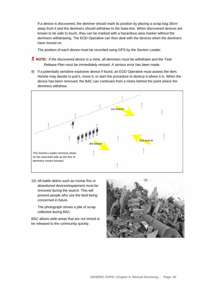
If a device is discovered, the deminer should mark its position by placing a scrap bag 30cm away from it and the deminers should withdraw to the base-line. When discovered devices are known to be safe to touch, they can be marked with a hazardous area marker without the deminers withdrawing. The EOD Operative can then deal with the devices when the deminers have moved on.
The position of each device must be recorded using GPS by the Section Leader.
NOTE: If the discovered device is a mine, all deminers must be withdrawn and the Task Release Plan must be immediately revised. A serious error has been made.
9) If a potentially sensitive explosive device if found, an EOD Operative must assess the item. He/she may decide to pull it, move it, or start the procedure to destroy it where it is. When the device has been removed, the BAC can continues from a metre behind the point where the deminers withdrew.
The Section Leader removes sticks on the searched side as the line of deminers moves forward.
1st search
2nd search 3rd search
10) All battle debris such as mortar fins or abandoned devices/equipment must be removed during the search. This will prevent people who use the land being concerned in future.
The photograph shows a pile of scrap collected during BAC.
BAC allows wide areas that are not mined to be released to the community quickly.
GENERIC SOPS: Chapter 6: Manual Demining – Page: 50

18. Area Reduction by BACS When no pressure or movement-sensitive mines and ERW are anticipated in an area and the Task Assessment indicates that there may be subsurface ordnance, the Task Supervisor may authorise areas to be processed using Battle Area Clearance Subsurface (BACS). BACS is an extension of traditional BAC methods in which deminers only search the area visually. In BACS, deminers search the area visually and with a rapid metal-detector search.
A BACS search can only be conducted on areas with sparse vegetation or from which vegetation has been removed. The BACS procedure does not constitute Clearance as defined in the IMAS, but it is an accepted Area Reduction and confidence building procedure. Land processed with BACS must NOT be released as Cleared. It should be released as being Reduced by BACS and having “No Known Threat”.
Working-distances during BACS are dictated by the interference range between detectors. The deminers are usually 10 metres apart but this distance may be reduced when the detectors do not interfere with each other. Lane marking and start and finish lines must be marked as for manual Clearance, except that side of lane marking can be placed at two metre intervals. Painted stones are usually used.
The metal-detector should be adjusted so that it does not signal on small pieces of metal but still signals on a piece of ordnance at 20cm. The ability to do this must be confirmed for each detector by conducting a test every time that the detector is switched off and on. The ordnance used for the test should normally be a rifle or hand grenade buried in a hole at 20cm depth and the hole filled with earth. The detector must signal clearly when passed over the buried device.
A base-stick is not generally used. The search-head is overlapped by 50% of its diameter and extended outside the lane at the sides by 20cm. This allows a rapid advance over areas where there are no large pieces of buried metal.
All battle debris such as mortar fins or abandoned devices/equipment must be removed during the search. This will prevent people who use the land being concerned in future.
If a device is discovered, the deminer should place a scrap-bag as a marker and withdraw to the start-line. When discovered devices are known to be safe to touch, they can be marked with a hazardous area marker without the deminer withdrawing. The EOD Operative can then deal with the devices when the deminer has moved on.
The position of each device should be recorded using GPS by the Section Leader.
NOTE: If the discovered device is a mine, all deminers must be withdrawn and the Task Release Plan must be immediately revised. A serious error has been made.
If a potentially sensitive explosive device if found, an EOD Operative must assess the item. He/she may decide to pull it, move it, or start the procedure to destroy it where it is. When the device has been removed, the BACS can continue from a metre behind the point where the deminer withdrew.
18.1 BACS detectors The metal-detector used may be a conventional detector that has been adjusted so that it does not signal on small pieces of metal. It may also be a conventional detector fitted with a large search-head. The large search-head enables the detector to find large items at greater depth, but stops the detector finding small pieces of metal at shallow depths. This means that it will not reliably find plastic-cased mines at any depth.
GENERIC SOPS: Chapter 6: Manual Demining – Page: 51

NOTE: A detector that has been tuned down or had a large search-head fitted can only be used when searching for large metal-cased ERW. They must never be used to search for plastic cased mines.
NOTE: Magnetometer detectors (which only find ferrous items) must not be used when searching for metal items that so not have a high ferrous content.
Except where ground is very electromagnetic and the metal-detector signals without apparent cause, the most efficient way to search wide areas for ordnance is by using a large-loop detector such as the Ebinger UPEX 740M large-loop detector. This detector is carried by two men as shown in the photograph below.
18.2 BACS with the UPEX 740M The UPEX 740M is used for searching areas where they may be ordnance deep under the ground and the predicted end-use of the land will involve digging deeply (such as when making foundations for buildings). It can also be useful for looking for metal-cased AT mines on roads. It is often used as a second process over ground that has already been Cleared of shallow mines using other tools.
NOTE: The UPEX 740M will NOT find minimum metal mines and should never be used in areas where any low-metal content mines are anticipated.
Before the search is conducted the vegetation in the area must be removed. When this is done mechanically, the ground should not be disturbed. If the ground has been disturbed, there may be more indications because surface scrap has become buried.
When there is ordnance or metal debris on the ground surface, the area should be BAC searched and surface ordnance and all debris removed before BACS is conducted.
The general rules for using the UPEX 740M are:
1. The UPEX 740M can only be used by staff who have been appropriately trained and tested. The detector must be set up in a prepared detector Calibration area. Assembly of the detector is complex and the manufacturer’s directions should be followed closely. Variations that allow more efficient batteries to be used are permitted. The sensitivity of the UPEX 740M must be set appropriately for the anticipated targets following the instructions in the handbook.
2. After calibration, the search-head must be passed over a Target ERW. The ERW should be an example of the smallest item that may be in the area. The default item is a 38mm rifle grenade. The search-head must be passed over the test-piece at the detection height (which
GENERIC SOPS: Chapter 6: Manual Demining – Page: 52

is generally 30cm unless otherwise specified in the Tasking order). The detector can only be used if there is a clear reading on the meter when the search-head is moved over the device.
3. The UPEX 740M detector is carried by two deminers. One carries the control panel and one end of the search-head and the second deminer carries the other end of the search-head and a bag of markers to place where there are indications. Another two deminers may be needed to move the marking forward as the search progresses. Indications are marked and the search is continued until the search area has been completed.
4. The UPEX 740M detector must be re-calibrated after every hour of use, or every time it is switched off. It should also be calibrated at any time when the users get erratic readings.
Before using the UPEX 740M, the search area must be prepared. The area should be marked out in boxes. Each box should be numbered and mapped on a Task Map and the corners of each box accurately recorded using GPS. The Task map showing the box positions and numbers should be provided to the Section Leader by the Platoon Commander.
A 3 x 3 metre metal-free detector Calibration area must be prepared outside the first Box.
The start-line marking in the first box must be removed and replaced by a tape (or rope) that can be stretched tight along the ground on the base-line. More tape must be stretched to make a line crossing the box between every side marker at two metre intervals.
When the box has been prepared, the search is conducted in this way:
1. The deminers move the search-head so that it is centrally over the stretched tape that marks the base-line.
The tape marking crossing the box every two metres can be moved forward by other deminers as the
search progresses.
3
1
2
Start position of search-head
1
The deminers walk slowly along the tape holding the search-head centrally over the tape. The search-head should always be less than 30cm above the ground surface and held level between the deminers.
2. At the other side of the box, the deminers move sideways so that the sides of the search-head are each over a tape. They walk back across the Box keeping the sides of the search-head over the tapes.
3. At the other side of the box, they position the search-head so that it is centrally over the second stretched tape and walk back across the box keeping the centre of the search-head over the tape.
GENERIC SOPS: Chapter 6: Manual Demining – Page: 53
This is continued over the entire box. The method means that the search-head is always overlapped by 50% to ensure complete ground coverage. Where the ground rises and falls, the deminers should ensure that the search-head follows the ground contours.
4. When there are indications, a deminer should place a marker to show the position of the detector reading. The stone should be placed on the centre of the indication. The indication is crudely “pinpointed” by moving the search-head back and forward and side to side.
When the UPEX 740M has been used over the entire Box, the deminers should move to search another box while other deminers investigate the markers they have placed.
NOTE: The UPEX 740M has a large search-head and there may be several small pieces of metal beneath it at one time. When this happens, the detector can give a reading as if one large piece of metal were present. After some of the metal has been removed, the UPEX 740M may no longer indicate over the same area.
After all indications have been investigated in a box, the UPEX 740M must be used to search over the excavated areas again to confirm that the indications have gone. When an indication is still there, further excavation should take place.
NOTE: THE UPEX 740M must not be used close to other metal-detectors because it is sensitive to electronic interference.
18.2.1 Signal investigation during BACS with the UPEX 740M Deminers can expose BACS signals using less caution than usual when the expected devices will not have a sensitive pressure plate like an AP mine, or be sensitive to movement. Extreme caution should be used when the devices may be movement sensitive (as are some submunitions).
The following procedure should be followed:
1. The deminers should use a standard metal-detectors to confirm the indication and should start to excavate 15cm back from the nearest-point marker.
2. When the indication cannot be confirmed, they should start to excavate 30cm back from the marker placed earlier. The ground above the indication should be removed to a depth of 10cm and the standard metal-detector should be used again to try to pinpoint the source. If no source is found, a further 10cm depth of ground over the indication must be removed. This should be repeated until the metal-detector can pinpoint the indication.
3. An excavation is then made to locate the indication pinpointed using the standard metal-detector. If the anticipated devices may be movement sensitive the deminer must investigate each indication with extreme caution. Excavation should be conducted as described in Part 8 of this Chapter.
4. When ERW is discovered, the deminer should withdraw. The Section Leader should inform the Platoon Commander who will instruct an EOD Operative to deal with the device. When the EOD Operative cannot attend immediately, and the ERW is not movement sensitive, the deminer can place a marker beside the device and continue to excavate other indications. When the device may be movement sensitive, the deminer should not investigate another indication within ten metres of the exposed device.
When excavation of a signal is taking place, the minimum working-distance between deminers should be not less than 10 metres.
When scrap metal or battle debris is found, it must be collected and placed in a designated scrap metal area.
GENERIC SOPS: Chapter 6: Manual Demining – Page: 54

18.3 BACS with the MineLab F3 The MineLab F3 has a simple way of reducing sensitivity so that it will not signal on small metal pieces. The detector has a coloured end-cap that is changed to adjust sensitivity. The Black end-cap is for normal sensitivity, the Red end-cap is for reduced sensitivity. When sensitivity is reduced, the detector can still locate large metal objects deep in the ground but will not signal on small fragments or minimum-metal mines.
NOTE: Never use the Red end-cap when searching for minimum-metal mines. The end-cap is Red so that the supervisor can easily see when it is being used and correct any error.
18.3.1 Changing the MineLab F3 to low sensitivity for BACS Sensitivity is changed by changing the end-cap at the end of the control box of the detector. The Black end-cap is the one normally used. The Red end-cap is used when searching for targets bigger than minimum-metal mines, so is used during BACS.
To change the end-cap, follow this procedure:
1. Ensure that the detector is switched off.
2. Place the thumb of one hand in the centre of the end-cap and curl the fingers under the bottom edge of the end-cap.
3. Push inwards with the thumb and at the same time pull the base of the end-cap away from the Control box as shown in the photograph alongside.
4. Hook the inside of the bottom of the Red end-cap under the bottom of the control box, then press with the palm of the hand to clip the red end-cap into position.
18.3.2 Using MineLab F3 detectors close together During BACS, it is usual for deminers to work as closely together as possible while avoiding interference between detectors.
The MineLab F3 detector can be used close together but they must be set up so that they do not interfere with each other.
To achieve this: 1. Mark the area and position each BACS deminer at the start of lanes three metres apart. 2. Ensure that all detectors are switched off. 3. Turn on the first detector and hold the search-head at least
60cm above the ground. 4. Press and immediately release the Noise Cancel button (the
Black Button positioned behind the handle).
5. Noise Cancel will start with two single beeps. These are followed by 45 seconds of sharp double beeps, and the process finishes with four single beeps.
6. During the 45 seconds, the detector scans the environment searching for any electrical interference. If disturbance is detected, the F3 will automatically select a different operating frequency.
7. After Noise Cancel has been completed for the first detector, leave it switched on and switch on the second detector.
8. Conduct the Noise Cancel procedure for that detector from Step 4 above. 9. Repeat this process for all detectors being used.
GENERIC SOPS: Chapter 6: Manual Demining – Page: 55
18.3.3 Procedure for BACS using the MineLab F3 BACS can only be conducted on areas where there is no threat of pressure or movement-sensitive mines and ERW. This may mean that the area to be searched can be walked over and marked out before the search is conducted.
Follow this procedure: 1. Remove the undergrowth over the area to be searched and mark out a start-line with
lanes three metres or more apart. 2. Make a metal-free detector Calibration area and a Test area outside the area to be
searched. Bury a target device at the required search-depth in the Test area. The default target is a 38mm rifle grenade which should be substituted with an example of the smallest ERW that might be present .
3. Fit the red end-caps to the MineLab F3 as described in Part 18.3.1 above. 4. Switch on and set up the MineLab F3 detector as described in Part 18.3.2 above. 5. Ensure that each deminer checks that the detector signals over the buried target in the
Test area. 6. Search in the lanes using a search-head advance of 50% of the search-head width (10cm
with the standard search-head). 1.2 metre wide lanes can be extended across the area to be searched without widening them to 2.2 metres. Search is generally rapid, so a base-stick need not be used but side of lane marking (stones or pickets) should be placed every two metres.
7. When there is a signal, the deminer must place a marker (usually a painted stone) at the nearest point of the signal. Because no pressure or movement-sensitive devices are expected, the deminer should continue the search past the signal marker. If the anticipated devices may be movement sensitive (such as some submunitions) the deminer must investigate each indication before continuing the search. Excavation should be conducted as described in Part 8 of this Chapter with extreme caution.
8. When the anticipated devices are not pressure or movement sensitive and a lane has been completely searched with markers placed, the deminer should return to the start of the lane and begin to excavate any marked signals, starting 15cm back from each marker. The excavation can be conducted less cautiously than when looking for mines.
9. When ERW is discovered, the deminer should withdraw. The Section Leader should inform the Platoon Commander who will instruct an EOD Operative to deal with the device. When an EOD Operative cannot attend immediately, the deminer can place a marker beside the device and continue to excavate other indications.
NOTE: When a discovered device may be movement sensitive, the deminer must inform the Section Leader who must inform all the deminers investigating signals to proceed with extreme caution. Deminers must not be allowed to investigate other indications within ten metres of the exposed device until it has been removed or destroyed.
10. After the reason for an indication has been discovered, the area must be searched again with the metal detector. If the detector still signals, the excavation must continue at least until the required depth of search has been reached.
When excavation of a signal is taking place, the minimum working-distance between deminers should be 10 metres.
GENERIC SOPS: Chapter 6: Manual Demining – Page: 56