2006 Fall MRS Presentation: "Gas Cluster Ge Infusion for Si(1-x)Ge(x) Strained-Layer Applications"
February 2003 Page 11 The Simulation Standard
Introduction Computer simulation is used extensively to verifyphysical phenomena in semiconductor devices.Meshing plays an essential role in obtaining good simu-lation results. If care is not properly taken, seriouserrors may occur in the results. The objective of thisarticle is to identify errors in the simulation of thestrained-Si heterostructure MOSFET device usingATLAS, Silvaco’s two-dimensional numerical simulator.
Simulation Structure Many research groups have extensively investigatedSi/SiGe heterostructure MOSFETs in recent years [1, 2]. Inthese structures, a Si channel is grown under tensile strainbetween relaxed SiGe layers. The strain induced conduc-tion band offset at the Si/SiGe heterointerface leads to theformation of a two-dimensional electron gas in the strainedSi layer that substantially enhances electron mobility inbulk silicon. Si/SiGe heterostructure MOSFETs thereforedeomonsterate excellent device performance.
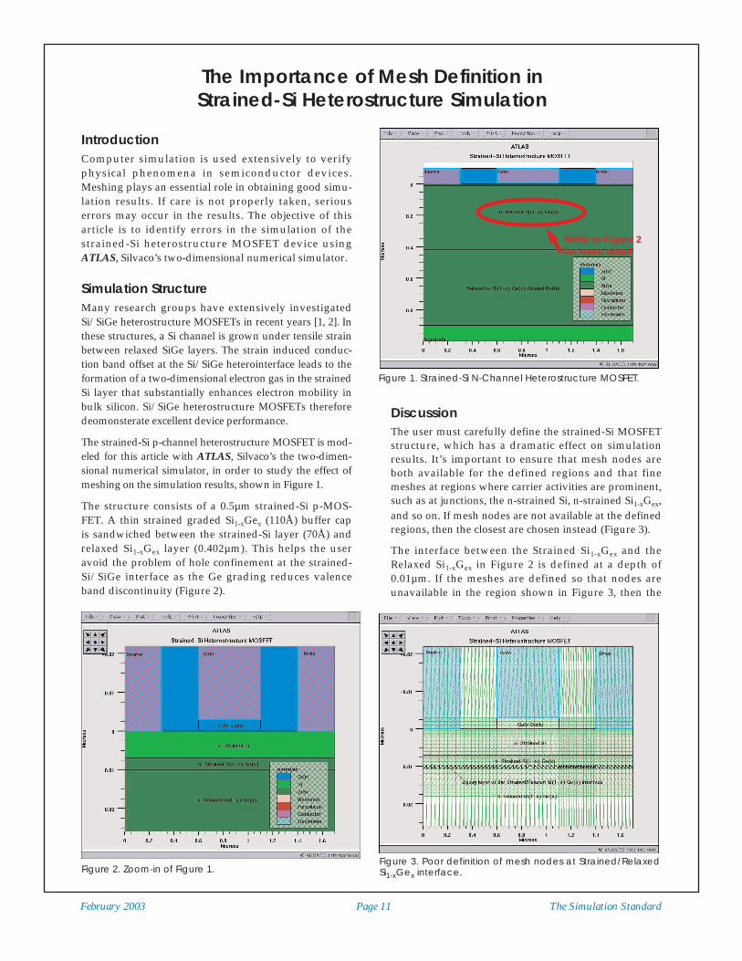
The strained-Si p-channel heterostructure MOSFET is mod-eled for this article with ATLAS, Silvaco’s the two-dimen-sional numerical simulator, in order to study the effect ofmeshing on the simulation results, shown in Figure 1.
The structure consists of a 0.5µm strained-Si p-MOS-FET. A thin strained graded Si1-xGex (110Å) buffer capis sandwiched between the strained-Si layer (70Å) andrelaxed Si1-xGex layer (0.402µm). This helps the useravoid the problem of hole confinement at the strained-Si/SiGe interface as the Ge grading reduces valenceband discontinuity (Figure 2).
DiscussionThe user must carefully define the strained-Si MOSFETstructure, which has a dramatic effect on simulationresults. It’s important to ensure that mesh nodes areboth available for the defined regions and that finemeshes at regions where carrier activities are prominent,such as at junctions, the n-strained Si, n-strained Si1-xGex,and so on. If mesh nodes are not available at the definedregions, then the closest are chosen instead (Figure 3).
The interface between the Strained Si1-xGex and theRelaxed Si1-xGex in Figure 2 is defined at a depth of0.01µm. If the meshes are defined so that nodes areunavailable in the region shown in Figure 3, then the
The Importance of Mesh Definition in Strained-Si Heterostructure Simulation
Figure 1. Strained-Si N-Channel Heterostructure MOSFET.
Figure 2. Zoom-in of Figure 1.
Refer to Figure 2for more detail
Figure 3. Poor definition of mesh nodes at Strained/RelaxedSi1-xGex interface.

The Simulation Standard Page 12 February 2003
interface between the Strained Si1-xGex and the RelaxedSi1-xGex forms a zig-zag pattern.
An incorrect simulation that results from poor meshdefinition is illustrated in Figure 4. The vertical inter-face between the n+ polysilicon and SiO2 is located at x= 1.1µm (Figure 2). If mesh nodes are not available at x =1.1µm, then the mesh appears as shown in Figure 4.
The formation of the zigzag layer appears in Figure 4 atthe interface x = 1.1µm. Some parts of the n+ polysiliconregion are not defined as an electrode, even though theREGION and the ELECTRODE statements are both definedas the same region:
region num=11 material=poly x.min=0.6 x.max=1.1 y.min=-0.1 y.max=-0.003
elec num=2 name=gate x.min=0.6
x.max=1.1 y.min=-0.1 y.max=-0.003
This is because there is no mesh node is available at x= 1.1µm. As a result, ATLAS believes both the node atx = 1.11µm is the x.max for the REGION statement andthe node at x = 1.08µm is the x.max for the ELECTRODEstatement. This poor definition of the mesh at thevertical interface between the n+ polysilicon and SiO2
results in the inaccurate simulation of the devicesshown in Figure 4.
The structure in Figure 4 is simulated by holding thedrain bias at 0.1V and then ramping the gate voltage to1.5V. Figure 5 is a plot of the simulated structure’scurrent flow and shows current flowing through theisolation oxide which is incorrect.
Figure 6 shows the simulated current flow lines withproper mesh definition at both the interface betweenthe strained Si1-xGex and the relaxed Si1-xGex, and thevertical interface between the n+ polysilicon and SiO2.All the current flow lines are confined within thesemiconductor region.
SummaryTo conclude, careful meshing is extremely important todevice simulation. Simulation software users mustcarefully allocate mesh nodes at the defined regions aswell as define fine meshes at regions of high activity.
References(1) G. A. Armstrong and Chinmay K. Maiti, "Strained-Si Channel
Heterojunction p-MOSFETs", Solid-State Electronics, Volume 42,Issue 4, April 1998, Pages 487-498
(2) P. A. Clifton, S. J. Lavelle and A. G. O'Neill, "Sub-micronStrained Si:SiGe Heterostructure MOSFETs", MicroelectronicsJournal, Volume 28, Issues 6-7, 9 August 1997, Pages 691-701
Figure 4. Poor mesh definition at vertical interface betweenthe n+ polysilicon and Silicon Dioxide.
Figure 5. Poor mesh definition which results in current flowingthrough the isolation oxide.
Figure 6. With proper mesh definition, the current flowlinesare confined within the semiconductor region.


![Tight binding studies of strained Ge/Si(001) growthucapdrb/Research/Preprints/GeMxN.pdf · The tight binding technique has been discussed elsewhere in detail[15], as have the ideas](https://static.fdocuments.in/doc/165x107/5f58473f9d949a37bc210496/tight-binding-studies-of-strained-gesi001-growth-ucapdrbresearchpreprintsgemxnpdf.jpg)