The Human Controller - ocw.tudelft.nl · The neuromuscular system can be modeled as a ... • A...
48
1 David Abbink – Human Controller |52 The Human Controller Frequency-Domain Analyses Teacher: • David ABBINK • BioMechanical Engineering, Delft University of Technology, The Netherlands Simulation - Neuromuscular control - Control of limbs - McRuer’s Cross-over model - Control of systems - Response of visual, vestibular and NMS feedback to driving or flying
Transcript of The Human Controller - ocw.tudelft.nl · The neuromuscular system can be modeled as a ... • A...

1David Abbink – Human Controller |52
The Human ControllerFrequency-Domain Analyses
Teacher:• David ABBINK• BioMechanical Engineering, Delft University of Technology, The Netherlands
Simulation
- Neuromuscular control - Control of limbs
- McRuer’s Cross-over model- Control of systems- Response of visual, vestibular and NMS
feedback to driving or flying

2David Abbink – Human Controller |52
So far…
1. About Perception1. All seven senses: physiology2. Measuring limits of perception3. Sensory Integration & Illusions
2. About Cognition1. The Brain: physiology 2. About feed-forward and feedback3. Skill, Rule, Knowledge based Behaviour
3. About Action1. The Neuromuscular System: Physiology, Adaptabilty
4. About Design and Evaluation1. Metrics vs Models

3David Abbink – Human Controller |52
Learning Goals
After this class you will be able to:
Reproduce:• McRuer’s crossover model and parameter sensitivity
Apply: • Frequency Domain Analysis to analyze Human Control
1. The basics: mass-spring-damper systems2. FRFs and models of neuromuscular systems3. FRFs and McRuer cross-over models
Critically Reflect on• Applicability of frequency domain analyses• Applicability of McRuer’s Crossover model

4David Abbink – Human Controller |52
Why bother Modeling?

5David Abbink – Human Controller |52
Own Car Lead Car
Vcar
Xcar
Xlead
Vlead
Xrel = Xlead - XcarVrel = Vlead - Vcar
THW = Xrel / VcarTTC = Xrel / -Vrel
SeparationStates
3. Cognition – route planning?Measuring and Modeling Performance

6David Abbink – Human Controller |52
Measure the impact of a new system by determining
• Statistical analysis (mean, std, CDF) of a dynamic signal• Change in performance metric for different systems (tunings)
Shortcomings • Time consuming• Descriptive, but not predictive (hard to generalize)• Many ways to achieve the same performance metric, unclear
what situations cause change in the metrics, or interaction between them
Systemoutput signal
System
new
3. Cognition – route planning?Coventional System Optimization
(relative speed)

7David Abbink – Human Controller |52
Systemoutputinput
Use System Identification Techniques to determine (causal and dynamic) relationships between input and output
System = output input
Coventional System OptimizationBetter way: use modeling!
8David Abbink – Human Controller |52
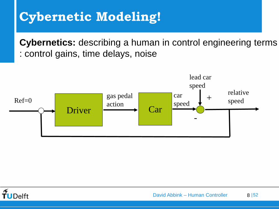
Cybernetics: describing a human in control engineering terms: control gains, time delays, noise
CarDriver
lead carspeed
gas pedalaction
carspeed
relativespeed
-
+Ref=0
Cybernetic Modeling!

9David Abbink – Human Controller |52
Advantages of this evaluation method:
• Quantitative -> objective• More information -> better understanding• Gives Predictive Models
Needed• Understanding of Control Engineering
• Bode plots• Fourier Analysis
Cybernetic Modeling!

10David Abbink – Human Controller |52
Basics of Frequency Domain Identification
11David Abbink – Human Controller |52
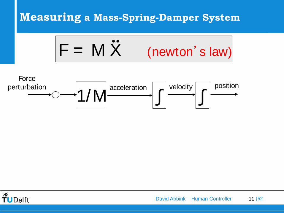
Simple Modeling of the Neuromuscular System
Measuring a Mass-Spring-Damper System
1/Macceleration
∫velocity
∫position
Force perturbation
F = M X (newton’s law)

12David Abbink – Human Controller |52
Simple Modeling of the Neuromuscular System
Measuring a Mass-Spring-Damper System
1/Macceleration
∫velocity
∫position
Force perturbation
F = M X + B X + K X
B
K
-
+
+
B
K
M

13David Abbink – Human Controller |52
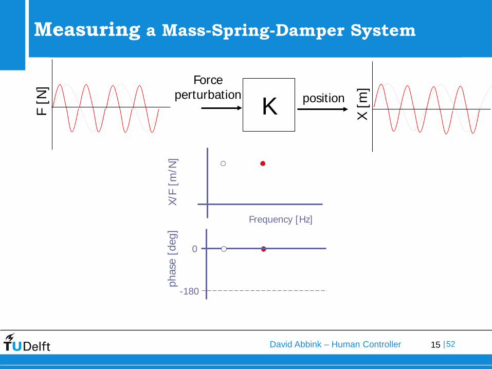
Simple Modeling of the Neuromuscular System
Measuring a Mass-Spring-Damper System
MBKForce
perturbation
F [N
]
K X [m
]
position
X/F
[m/N
]
Frequency [Hz]
phas
e [d
eg]
0
-180

14David Abbink – Human Controller |52
Simple Modeling of the Neuromuscular System
Measuring a Mass-Spring-Damper System
Force perturbation
F [N
]
2K X [m
]
position
X/F
[m/N
]
Frequency [Hz]
phas
e [d
eg]
0
-180
15David Abbink – Human Controller |52
Simple Modeling of the Neuromuscular System
Measuring a Mass-Spring-Damper System
MBKForce
perturbationK X [m
]
position
X/F
[m/N
]
Frequency [Hz]
phas
e [d
eg]
0
-180
F [N
]

16David Abbink – Human Controller |52
Simple Modeling of the Neuromuscular System
Measuring a Mass-Spring-Damper System
MBKForce
perturbation
X [m
]
position
X/F
[m/N
]
Frequency [Hz]
phas
e [d
eg]
0
-180
F [N
]

17David Abbink – Human Controller |52
Simple Modeling of the Neuromuscular System
Measuring a Mass-Spring-Damper System
MBKForce
perturbation
X [m
]
position
X/F
[m/N
]
Frequency [Hz]
phas
e [d
eg]
0
-180
F [N
]
18David Abbink – Human Controller |52
Frequency Domain Identification – applied to NMS control

19David Abbink – Human Controller |52
α
F
1. Impose Force Perturbation
2. Task Instruction
3. Measure Signals• Pedal Force• Pedal Displacement• Force Perturbation
4. Estimate Admittance
Simple Modeling of the Neuromuscular System
Measuring the Neuromuscular System

20David Abbink – Human Controller |52
can be estimated as frequency response functioninput force/torque output position/rotation
captures causal dynamic response of a human to interaction forces with the environment
K B
IRoughly resembles 2nd
order system
Highly adaptive!
Admittance:
X/F
frequency
Measuring the Neuromuscular System

21David Abbink – Human Controller |52
FT: Force TaskRT: Relax TaskPT: Position Task
Measuring the Neuromuscular System
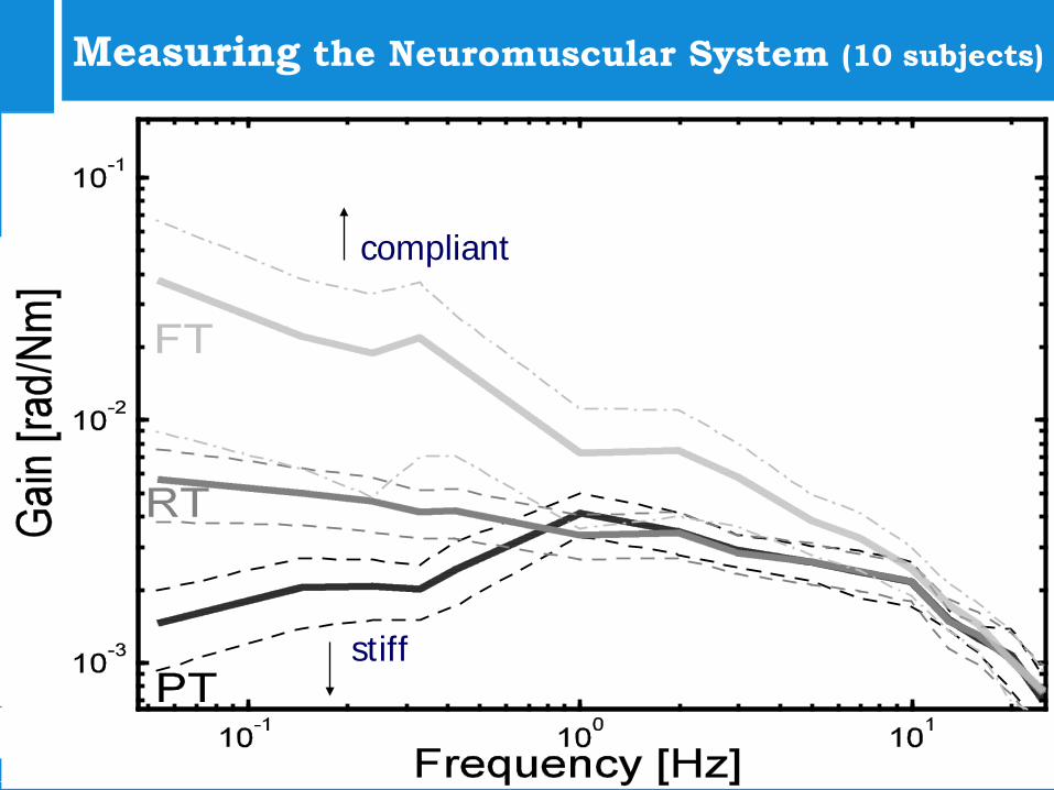
22David Abbink – Human Controller |52
Results for 10 subjects
compliant
stiff
Measuring the Neuromuscular System (10 subjects)

23David Abbink – Human Controller |52
The Role of the Neuromuscular System in visual / vestibular control loops

24David Abbink – Human Controller |52
- -
Sensors Equalization VehicleDynamics
Displays NeuromuscularSystem
ControlInceptor
+
-
--
-
Feed-forward
Feed-back
Neuromuscular System during Pitch Control

25David Abbink – Human Controller |52
Stiff, like POS, from co-contraction or reflexive feedback
Grip is very stiff
Compliant, like FOR
Reflexive feedback activity
Neuromuscular System during Pitch Control

26David Abbink – Human Controller |52
Interested in more information aboutmeasuring and modeling the NMS?
Follow:Human Movement Control A/B
Play around with:NMC Lab – a graphical user interface (GUI) to study the Delft Neuromuscular Model
Read:-Schouten et al. (2008)-Mugge & Abbink et al. (2011) -Abbink et al. (2012)

27David Abbink – Human Controller |52
•The Cross-Over Model • Background & Theory
• D. T. McRuer and H. R. Jex, “A review of quasi-linear pilot models”, IEEE Trans. Hum. Fact. 8, 231–249 (1967)
CarDriver
lead carspeed
gas pedalaction
carspeed
relativespeed
-
+Ref=0

28David Abbink – Human Controller |52
Order of Control
• Order of control denotes the number of integrations between the human’s control movement and the output of the system being controlled.
• Highest derivative in the differential equation

29David Abbink – Human Controller |52
Zero-order system
• Also called position control – pure gain
30David Abbink – Human Controller |52
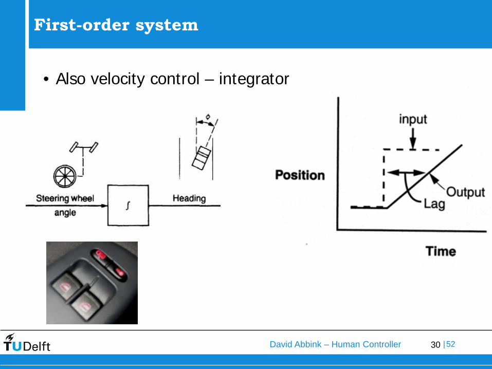
First-order system
• Also velocity control – integrator

31David Abbink – Human Controller |52
Second - order system
• Also called acceleration control

32David Abbink – Human Controller |52
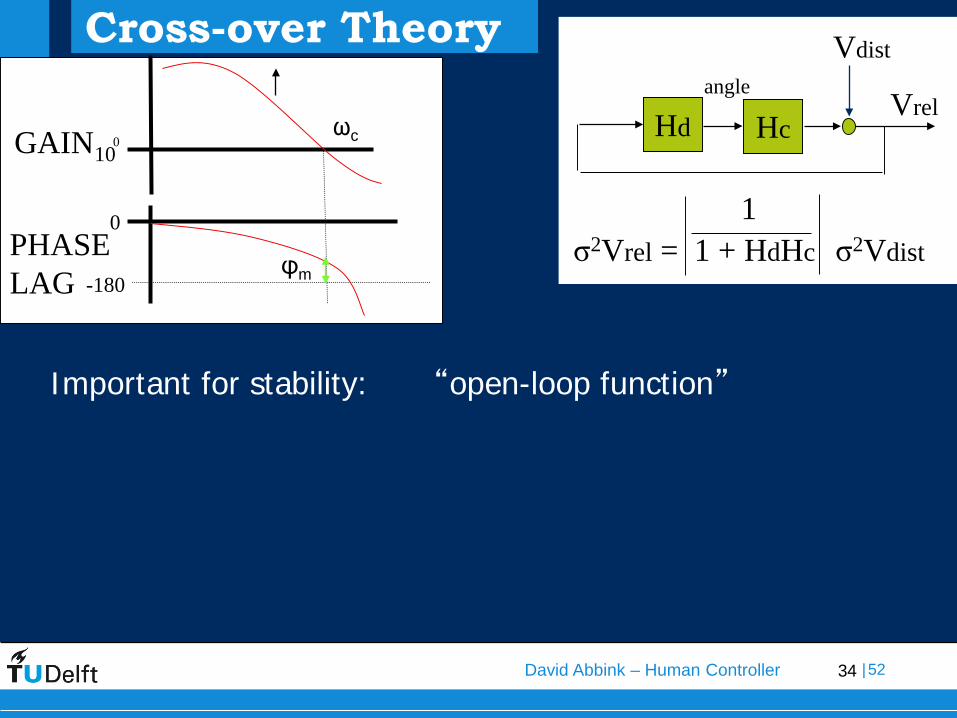
Crossover Model (McRuer)
The adapted ‘cross-over model’: (near ωc)
Once adapted to the dynamics, humans can • increase gain (ωc)• decrease time delay
Thereby influencing the properties of the total closed-loop system
Humans can adapt their control behaviour to steer position, velocity or acceleration (using prediction or memory), within limits:
Humans prefer the closed-loop controlled system to behavelike a “first-order system”

33David Abbink – Human Controller |52
Cross-over Theory
The cross-over model: near ωc
Properties of the Open-Loop systemCrossover Frequency ωc Measure of effortPhase Margin φm Measure of stability (safety)
ejcdriver carH H e
jωτω
ω−=
-180
ωc
0
0
φm
10GAIN
PHASELAG
34David Abbink – Human Controller |52
PHASELAG -180
ωc
0
0
φm
10GAIN
Cross-over Theory
Hd HcVrel
σ2Vrel = 1 + HdHc σ2Vdist1
Vdistangle
Important for stability: “open-loop function”

35David Abbink – Human Controller |52
•Cross-Over Model & NeuromuscularSystem
How do visual, vestibular and NMS feedback combine?

36David Abbink – Human Controller |52
McRuer’s Lumped Neuromuscular System
- -
The neuromuscular system is usually considered as a limitation, and can be seen as a controller-actuator system between udesired and urealized
The neuromuscular system can be modeled as a first or second-order low-pass filter:Lumped neuromuscular system.
Sensors Equalization VehicleDynamics
Displays NeuromuscularSystem
ControlInceptor
+
udesired urealized
Hlumped =
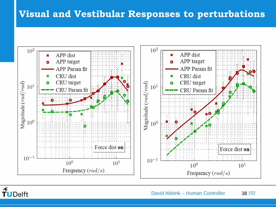
The lumped neuromuscular system model parameters can be obtained from the identified visual and vestibular frequency response functions.

37David Abbink – Human Controller |52
The Lumped Neuromuscular System
- -
Two forcing functions are needed to identify the contributions of the visual and vestibular systems separately:
Sensors Equalization VehicleDynamics
Displays NeuromuscularSystem
ControlInceptor
+
• A second forcing function perturbs the elevator of the aircraft.• A forcing function provides a pitch attitude command signal on the PFD.
38David Abbink – Human Controller |52
Visual and Vestibular Responses to perturbations

39David Abbink – Human Controller |52
•Cross-Over Model & NeuromuscularSystem
How do visual and NMS feedback contribute to car-following behaviour in case of haptic gas pedalfeedback?

40David Abbink – Human Controller |52
Subjects:5 male, 5 female subjectsExperimental Conditions:
• V (drive with visual feedback)• VH (drive with visual and haptic feedback)• H (drive with haptic feedback only)
Goal: Experimentally Investigate impact of haptic DSS on car followingAND neuromuscular control behaviour
Experimental Facilities1. Simplified Simulator (ME),
capable of admittance measurements
2. Realistic Fixed Base Driving Simulator (AE) for checking
Evaluation – Car Following with Haptic Driver Support System (DSS)

41David Abbink – Human Controller |52
Task InstructionMaintain a constant THW of0.5, 1 or 1.5 [s]by using the gaspedal toaccelerate and decelerate
Perturbation: Lead vehicle Speed ProfileUnpredictable MultiSine
Each condition: 4 repetitions of 94 s
Task Instruction & Perturbation

42David Abbink – Human Controller |52
Car-following experimentExperimental results: classical metrics
Performance (std 1/TTC)• IDSS increased performance
IDSS off 0.5
IDSS on 0.5
IDSS off 1.0
IDSS on 1.0
IDSS off 1.5
IDSS on 1.5
Required THW [s]
0.00
0.10
0.20
0.30
0.40
STD(
1/TTC
) [1/s
]
Disturbance bandwidth [Hz]
0.30.50.7
IDSS off 0.5
IDSS on 0.5
IDSS off 1.0
IDSS on 1.0
IDSS off 1.5
IDSS on 1.5
Required THW [s]
10.00
15.00
20.00
25.00
30.00
STD(
alpha
) [%]
Disturbance bandwidth [Hz]
0.30.50.7
Effort (std Pedal Depression)• IDSS decreased effort

43David Abbink – Human Controller |52
Car-following experiment Experimental results: classical metrics (for THW=1, Bandwidth = 0.5)

44David Abbink – Human Controller |52
Car-following experiment Experimental results: frequency domain and time domain
45David Abbink – Human Controller |52
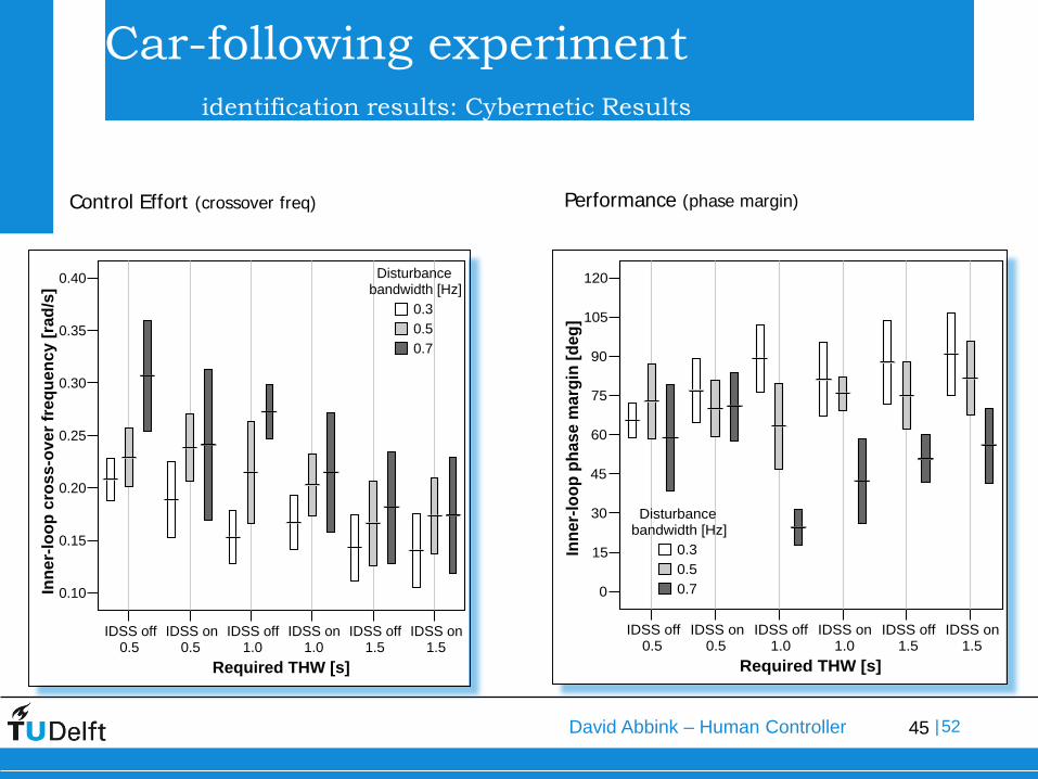
Car-following experiment identification results: Cybernetic Results
IDSS off 0.5
IDSS on 0.5
IDSS off 1.0
IDSS on 1.0
IDSS off 1.5
IDSS on 1.5
Required THW [s]
0.10
0.15
0.20
0.25
0.30
0.35
0.40
Inne
r-lo
op c
ross
-ove
r fre
quen
cy [r
ad/s
]
Disturbance bandwidth [Hz]
0.30.50.7
IDSS off 0.5
IDSS on 0.5
IDSS off 1.0
IDSS on 1.0
IDSS off 1.5
IDSS on 1.5
Required THW [s]
0
15
30
45
60
75
90
105
120
Inne
r-lo
op p
hase
mar
gin
[deg
]
Disturbance bandwidth [Hz]
0.30.50.7
Control Effort (crossover freq) Performance (phase margin)

46David Abbink – Human Controller |52
Car-following experiment identification results: Cybernetic Results
Modeled Time delay decreases with haptic gas pedal feedback
• More time available
But what is the cause?
IDSS off 0.5
IDSS on 0.5
IDSS off 1.0
IDSS on 1.0
IDSS off 1.5
IDSS on 1.5
Required THW [s]
0.00
0.25
0.50
0.75
1.00
1.25
1.50
1.75
tau
[s]
Disturbance bandwidth [Hz]
0.30.50.7

47David Abbink – Human Controller |52
Beneficial changes in Car-Following Behaviour:Performance (deviations in Xrel, THW, Vrel, iTTC)
• Similar or slightly betterControl Effort (deviations in pedal position, muscle activity)
• Decrease
How? Look at changes in Neuromuscular Control BehaviourAdmittanceModeling
Driving with only haptic (H) feedback possible
Haptic Gas Pedal Evaluation – Exp.

48David Abbink – Human Controller |52
Study Human Control Behaviour with MMS -Lab
• Group Enroll (available now)• Download from BlackBoard (available tomorrow)
Do experiment• Test several conditions on yourself
• 1st order, 2nd order system, 3rd order system (normal)• 1st order, 2nd order system, 3rd order system (with
predictor)• Save each of the data files and two plots
• (time-domain, frequency domain) • Report in a short presentations
• Report results in time domain and frequency domain• Discuss results in terms of McRuer Cross-over
modelding• Discuss inter- and intra-subject variability
Next Class – ‘Computerzaal B’ (TBM)