
The Hot-One System - DME System...Provide a gate dimple on core/cavity opposite gate, ... GMB EHR...
41
36 D-M-E Runnerless Molding Systems 3x H Ø 3x H Ø H Ø 1,27 Ø EHR TCG GMB SCH GMT Ø 17,5 25,4 Ø 38 Ø 19 A/A1 L1 L The Hot-One System Body Seal ring Square TC type 'J' coil heater Gate Mate 4 TM nozzles Types - GMB SUB-ASSEMBLY consisting of : REF. Sub-Assembly Standard Hot-One system The Gate Mate 4 TM nozzle is used under a hot mani- fold and is ideal for fast-cycling multi-cavity molds and thin walled parts. Its compact design permits centerline-to-centerline distances for use in smaller molds, or increased cavitation in larger molds. Thermocouple placement provides better heater control and the overall nozzle design gives improved thermal insulation. Heater, thermocouple and tip are both replaceable. The Gate Mate 4 TM is available in a wide variety of lengths and can be fitted with five different tip styles, allowing a great flexibility in applications, with most types of plastic materials and a broad range in mol- ding weight. GMB Gate Mate 4 TM REF. A* A1* L L1 GMB 0150 EX 50,8 49,8 25,0 36,5 GMB 0151 EX 63,5 62,5 37,5 49,0 GMB 0152 EX 76,2 75,2 50,0 62,0 GMB 0153 EX 88,9 87,9 63,0 74,5 GMB 0154 EX 101,6 100,6 75,5 87,5 GMB 0155 EX 127,0 126,0 101,0 113,0 GMB 0156 EX 152,4 151,4 136,5 138,0 Note: Dim A1 refers to the Thru hole tip. Tip to be ordered separately. (*dim. at room temperature) GMB 0150 EX ◆ SCH 0060 TCG 0060 GMB 0151 EX ◆ SCH 0061 TCG 0061 GMB 0152 EX ◆ SCH 0062 TCG 0062 GMB 0153 EX ◆ EHR 0155 SCH 0063 TCG 0063 GMB 0154 EX ◆ SCH 0064 TCG 0064 GMB 0155 EX ◆ SCH 0065 TCG 0065 GMB 0156 EX ◆ SCH 0066 TCG 0066 Tips for Gate Mate 4 TM nozzles - GMT Standard Used with general purpose materials. Standard tip is made of copper alloy. REF. H Ø GMT 2 44 0,61 Hard wear Used with abrasive materials. Hard wear tip is made of carbide. REF. H Ø GMT 0300 44 0,61 Super sharp Used with small gates. Super sharp tip is made of copper alloy. REF. H Ø GMT 0301 44 0,25 Thru hole Used to eliminate potential flow lines. Thru hole tip is made of copper alloy. REF. H Ø GMT 0302 43 2,29 No hole Used to align the flow lines. No hole tip is made of copper alloy. REF. H Ø GMT 0303 44 0,61 How to order To order a complete Gate Mate 4 TM GMB nozzle: 1. Select one of the available Sub- Assembly reference numbers. 2. Select the reference number of the corresponding tip. 3. Both reference numbers as listed under 1. and 2. are required to get the right delivery. H Ø 4x H Ø SCH TCG GMB EHR
Transcript of The Hot-One System - DME System...Provide a gate dimple on core/cavity opposite gate, ... GMB EHR...

36D-M-E Runnerless Molding Systems
3x
H
Ø3x
H
Ø
H
Ø 1,27
Ø
EHRTCGGMBSCHGMT
Ø 1
7,5
25,4
Ø 3
8
Ø 1
9
A/A1
L1
L
The Hot-One System
Body Seal ring Square TC type 'J'coil heater
Gate Mate 4TM nozzles
Types - GMB
SUB-ASSEMBLY consisting of :
REF.Sub-Assembly
Standard Hot-One system
The Gate Mate 4TM nozzle is used under a hot mani-fold and is ideal for fast-cycling multi-cavity molds andthin walled parts. Its compact design permitscenterline-to-centerline distances for use in smallermolds, or increased cavitation in larger molds.Thermocouple placement provides better heatercontrol and the overall nozzle design gives improvedthermal insulation.
Heater, thermocouple and tip are both replaceable.The Gate Mate 4TM is available in a wide variety oflengths and can be fitted with five different tip styles,allowing a great flexibility in applications, with mosttypes of plastic materials and a broad range in mol-ding weight.
GMBGate Mate 4TM
REF. A* A1* L L1GMB 0150 EX 50,8 49,8 25,0 36,5GMB 0151 EX 63,5 62,5 37,5 49,0GMB 0152 EX 76,2 75,2 50,0 62,0GMB 0153 EX 88,9 87,9 63,0 74,5GMB 0154 EX 101,6 100,6 75,5 87,5GMB 0155 EX 127,0 126,0 101,0 113,0GMB 0156 EX 152,4 151,4 136,5 138,0
Note: Dim A1 refers to the Thru hole tip.Tip to be ordered separately. (*dim. at room temperature)
GMB 0150 EX SCH 0060 TCG 0060GMB 0151 EX SCH 0061 TCG 0061GMB 0152 EX SCH 0062 TCG 0062GMB 0153 EX EHR 0155 SCH 0063 TCG 0063GMB 0154 EX SCH 0064 TCG 0064GMB 0155 EX SCH 0065 TCG 0065GMB 0156 EX SCH 0066 TCG 0066
Tips for Gate Mate 4TM nozzles - GMTStandard
Used with general purpose materials.Standard tip is made of copper alloy.
REF. H Ø
GMT 2 44 0,61
Hard wear
Used with abrasive materials.Hard wear tip is made of carbide.
REF. H Ø
GMT 0300 44 0,61
Super sharp
Used with small gates.Super sharp tip is made of copper alloy.
REF. H Ø
GMT 0301 44 0,25
Thru hole
Used to eliminate potential flow lines.Thru hole tip is made of copper alloy.
REF. H Ø
GMT 0302 43 2,29
No hole
Used to align the flow lines.No hole tip is made of copper alloy.
REF. H Ø
GMT 0303 44 0,61
How to orderTo order a complete Gate Mate 4TM
GMB nozzle:1. Select one of the available Sub-
Assembly reference numbers.2. Select the reference number of
the corresponding tip.3. Both reference numbers as
listed under 1. and 2. arerequired to get the right delivery.
H
Ø
4x
H
Ø
SCH TCG GMB EHR

D-M-E Runnerless Molding Systems37
Ø 19
land
(m
ax)
To suit
80°
Max 4.5
Z
R5 spherical radius
Min 1
0.15
0.8
90°
Wiring channel
Manifold line
F*
in o
pera
ting
tem
pera
ture
Max
20
H6
H6
R3
R9,5
Z
Min
6
25.4
16
Ø 40
Ø 38
Ø 32
3.5
20
F*
= A
+
A
30°
Ø 19
R3
The Hot-One System
Standard Hot-One systemInstallation Instructions - Gate Mate 4TM nozzle - GMB
Gating
Fitting instructions
1. Machine the nozzle's seat directly into the mold forbest results.
2. For best gate appearance (lowest gate vestige),design tip to be ,0 to 0,13 mm back from the cavityat room temperature. Maintain a minimumclearance of 0,25 mm around the tip through thegate in the "hot" position. To achieve best materialflow, position tip up to 0,5 mm maximum back fromcavity. This position will result in a higher gatevestige.
3. Provide maximum water cooling in cavity insertaround gate.
4. Machine seat area following dimensions carefully.Hold the 19H6 diameter, as this is a seal-offdimension.
5. Ensure minimal thermal contact between nozzleand mold, especially under nozzle shoulder.
6. Route wires through wire channel in retainer plate.7. Provide a gate dimple on core/cavity opposite gate,
this will allow for best material flow.
Gate shell insulator - GSIIt fills the space near the gate in Gate Mate 4TM typeapplications. This avoids stagnation of the injectedplastic material near the gate, and makes colorchanges easier. The material used is virgin Polyimide,selected for its unique mechanical, thermal and chemicalresistance. Its stability in long periods of time and itslow thermal conductivity make it an ideal choice.Moreover, the slightly elastic behaviour of virgin Polyimi-de ensures a perfect sealing of the gate shell space.The Gate shell insulator is particularly suitable wheninjecting plastic materials that degrade easily, eithershort or long term. In many cases, the frozen layer ofthe processed resin will be eliminated completely sothat no stagnation will occur.
REF. A A1GMB 0150 EX 50,8 49,8GMB 0151 EX 63,5 62,5GMB 0152 EX 76,2 75,2GMB 0153 EX 88,9 87,9GMB 0154 EX 101,6 100,6GMB 0155 EX 127,0 126,0GMB 0156 EX 152,4 151,4
Dim. A1 refers to the thru hole tip.IMPORTANT: Use also "A" value for the installation of thru hole tips.
Note:The expansion factor must be taken into considerationprior to machining for, and installing nozzle.∆A = A x αc x 10-6 x ∆Tαc = 16,8 - 0,026 x A∆T = nozzle set point - 20°C
Example:Given a 127 mm A dimension, with a nozzle setpointtemperature of 260 °C.∆ A = 127 x (16,8 - 0,026 x 127) x 10-6 x (260 - 20 °C) = 0,41 mmThus F* = 127 + 0,41 = 127,41 mm
Please note that the above information is given as anexample and not valid for GMT 0300. Use half the valuefor carbide tips. Variations may occur based on moldconfigurations and cooling factor. In some instances, itmay be necessary to obtain an empirical factor.
REF.GSI 0001
Installation
~

38D-M-E Runnerless Molding Systems
GMB
SCH
TCG
EHR
GMT
Ø 3
8,1
Ø 1
5,87
50.8
34.9(A)
CIH
GMB
GMT
EHR50.8
34.9(A)
Ø 1
5,87
Ø 3
8,1
Body Seal ring Square coil TC type 'J' Tipheater
Mini Gate Mate Nozzles
Types - GMB
ASSEMBLY consisting of :
REF.Assembly
REF.
GMB 0108
Standard Hot-One system
GMB 0108 EHR 0155 SCH 0004 TCG 0100 GMT 0100
SCH TCG GMB EHR CIH GMB EHR
Body Seal ring Cast-in heater TipwithTC type 'J'
ASSEMBLY consisting of :
REF.Assembly
REF.
GMB 0100 GMB 0100 EHR 0155 CIH 0100 GMT 0100
Mini Gate Mate with Cast-in heater
Mini Gate Mate with Square coil heater
Remark: Tip is not recommended for abrasive materials.For applications involving highly abrasive engineeringgrade resins, contact D-M-E.
Installation Instructions Gating
±0,
2
H7
±0,
2H6
±0,
2
Ø 3
5
Ø 3
8,1
Ø 4
0
10.2
(*) F
Ø 1
5,87
30°
Ø 2
8,5
1
14
H6
2
R 3.2
Ø 15,87
30°
30°
10.2
Ø 0,8 min
90°
0,1
max
cyl
.
(*)F = A + ∆A∆A = A x (11,4 x 10⁻⁶) x ∆T∆T = T max °C - 20 °C
The Hot-One System
The Hot-One System
D-M-E Runnerless Molding Systems39
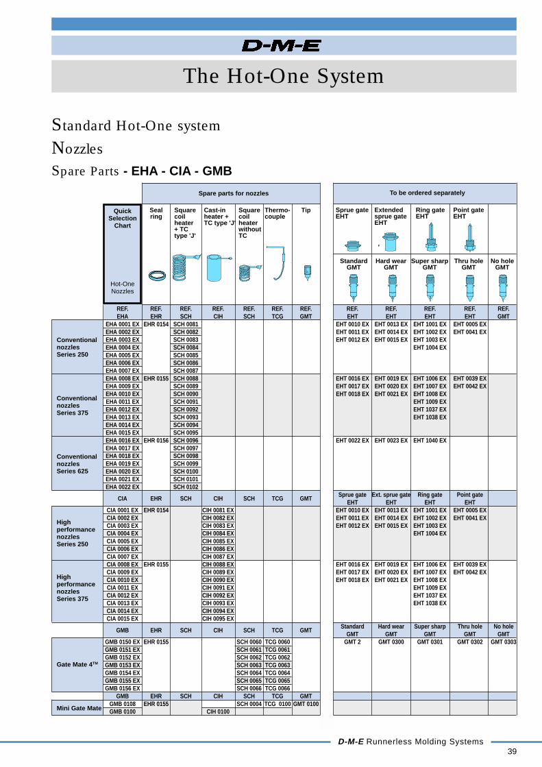
To be ordered separately
QuickSelection
Chart
Hot-OneNozzles
Sprue gate Extended Ring gate Point gateEHT sprue gate EHT EHT
EHT
Standard Hard wear Super sharp Thru hole No holeGMT GMT GMT GMT GMT
ConventionalnozzlesSeries 250
ConventionalnozzlesSeries 375
ConventionalnozzlesSeries 625
HighperformancenozzlesSeries 250
HighperformancenozzlesSeries 375
Gate Mate 4TM
Mini Gate Mate
Spare Parts - EHA - CIA - GMB
Standard Hot-One system
Seal Square Cast-in Square Thermo- Tipring coil heater + coil couple
heater TC type 'J' heater+ TC withouttype 'J' TC
REF. REF. REF. REF. REF. REF. REF. REF. REF. REF. REF. REF.EHA EHR SCH CIH SCH TCG GMT EHT EHT EHT EHT GMT
EHA 0001 EX EHR 0154 SCH 0081 EHT 0010 EX EHT 0013 EX EHT 1001 EX EHT 0005 EXEHA 0002 EX SCH 0082 EHT 0011 EX EHT 0014 EX EHT 1002 EX EHT 0041 EXEHA 0003 EX SCH 0083 EHT 0012 EX EHT 0015 EX EHT 1003 EXEHA 0004 EX SCH 0084 EHT 1004 EXEHA 0005 EX SCH 0085EHA 0006 EX SCH 0086EHA 0007 EX SCH 0087EHA 0008 EX EHR 0155 SCH 0088 EHT 0016 EX EHT 0019 EX EHT 1006 EX EHT 0039 EXEHA 0009 EX SCH 0089 EHT 0017 EX EHT 0020 EX EHT 1007 EX EHT 0042 EXEHA 0010 EX SCH 0090 EHT 0018 EX EHT 0021 EX EHT 1008 EXEHA 0011 EX SCH 0091 EHT 1009 EXEHA 0012 EX SCH 0092 EHT 1037 EXEHA 0013 EX SCH 0093 EHT 1038 EXEHA 0014 EX SCH 0094EHA 0015 EX SCH 0095EHA 0016 EX EHR 0156 SCH 0096 EHT 0022 EX EHT 0023 EX EHT 1040 EXEHA 0017 EX SCH 0097EHA 0018 EX SCH 0098EHA 0019 EX SCH 0099EHA 0020 EX SCH 0100EHA 0021 EX SCH 0101EHA 0022 EX SCH 0102
CIA EHR SCH CIH SCH TCG GMTSprue gate Ext. sprue gate Ring gate Point gate
EHT EHT EHT EHTCIA 0001 EX EHR 0154 CIH 0081 EX EHT 0010 EX EHT 0013 EX EHT 1001 EX EHT 0005 EXCIA 0002 EX CIH 0082 EX EHT 0011 EX EHT 0014 EX EHT 1002 EX EHT 0041 EXCIA 0003 EX CIH 0083 EX EHT 0012 EX EHT 0015 EX EHT 1003 EXCIA 0004 EX CIH 0084 EX EHT 1004 EXCIA 0005 EX CIH 0085 EXCIA 0006 EX CIH 0086 EXCIA 0007 EX CIH 0087 EXCIA 0008 EX EHR 0155 CIH 0088 EX EHT 0016 EX EHT 0019 EX EHT 1006 EX EHT 0039 EXCIA 0009 EX CIH 0089 EX EHT 0017 EX EHT 0020 EX EHT 1007 EX EHT 0042 EXCIA 0010 EX CIH 0090 EX EHT 0018 EX EHT 0021 EX EHT 1008 EXCIA 0011 EX CIH 0091 EX EHT 1009 EXCIA 0012 EX CIH 0092 EX EHT 1037 EXCIA 0013 EX CIH 0093 EX EHT 1038 EXCIA 0014 EX CIH 0094 EXCIA 0015 EX CIH 0095 EX
GMB EHR SCH CIH SCH TCG GMTStandard Hard wear Super sharp Thru hole No hole
GMT GMT GMT GMT GMTGMB 0150 EX EHR 0155 SCH 0060 TCG 0060 GMT 2 GMT 0300 GMT 0301 GMT 0302 GMT 0303GMB 0151 EX SCH 0061 TCG 0061GMB 0152 EX SCH 0062 TCG 0062GMB 0153 EX SCH 0063 TCG 0063GMB 0154 EX SCH 0064 TCG 0064GMB 0155 EX SCH 0065 TCG 0065GMB 0156 EX SCH 0066 TCG 0066
GMB EHR SCH CIH SCH TCG GMTGMB 0108 EHR 0155 SCH 0004 TCG 0100 GMT 0100GMB 0100 CIH 0100
Nozzles
Spare parts for nozzles

47.5
L
Ø ID
Ø D
40D-M-E Runnerless Molding Systems
D I.D.
L
The Hot-One System
Nozzles
Spare Parts - EHA - CIA - GMB
Standard Hot-One system
EHR
REF. Dc nom. ID Do D DL max. Mat.EHR 0154 6,30 11,10 14,25 14,35 11,10EHR 0155 9,50 14,27 17,42 17,55 12,70EHR 0156 22,20 23,80 26,97 27,08 23,80 AluminiumEHR 0160 12,70 17,45 20,62 20,80 16,00EHR 0162 16,00 19,05 22,22 22,37 17,50EHR 1145 4,00 6,70 9,50 9,55 5,20EHR 1150 5,25 9,56 12,70 12,75 8,00EHR 1154 8,00 11,10 14,25 14,35 9,50EHR 1155 9,50 14,27 17,42 17,55 12,70EHR 1156 18,00 23,80 26,97 27,08 23,80 StainlessEHR 1160 12,70 17,45 20,62 20,80 16,00 SteelEHR 1162 16,00 19,05 22,22 22,37 17,50EHR 1165 17,50 21,00 24,14 24,20 18,00EHR 1168 22,20 26,97 30,18 30,25 25,40
Seal ring
CIHCast-in heater with thermocouple type 'J' for CIA & GMB
Installation
Length of wires 850 mmBlack wire 230 VBlack wire 230 VWhite wire +Red wire - TC type 'J'
Tip for Mini Gate Mate
Tip is not recommended forabrasive materials
REF. For
GMT 0100 GMB 0108GMB 0100
CIHRemoval toolfor Cast-in heaters
REF.
CIH 9000
SCH
REF. For L ID D Watt Series230V
SCH 0081 EHA 0001 EX 51,00 275SCH 0082 EHA 0002 EX 63,50 320SCH 0083 EHA 0003 EX 76,00 370SCH 0084 EHA 0004 EX 89,00 15,37 21,00 390 250SCH 0085 EHA 0005 EX 101,50 460SCH 0086 EHA 0006 EX 127,00 460SCH 0087 EHA 0007 EX 152,50 500SCH 0088 EHA 0008 EX 54,00 370SCH 0089 EHA 0009 EX 66,50 415SCH 0090 EHA 0010 EX 79,50 500SCH 0091 EHA 0011 EX 92,00 640SCH 0092 EHA 0012 EX 105,00
21,72 27,00735
375
SCH 0093 EHA 0013 EX 130,00 825SCH 0094 EHA 0014 EX 156,50 920SCH 0095 EHA 0015 EX 181,00 1000SCH 0096 EHA 0016 EX 101,50 920SCH 0097 EHA 0017 EX 127,00 950SCH 0098 EHA 0018 EX 152,50 1000SCH 0099 EHA 0019 EX 178,00 37,47 43,00 1000 625SCH 0100 EHA 0020 EX 203,00 1100SCH 0101 EHA 0021 EX 228,50 1100SCH 0102 EHA 0022 EX 254,00 1100
Square coil heater with thermocouple type 'J' for EHA
GMT
REF. For L ID DWatt
Series230V
CIH 0081 CIA 0001 EX 52,37 275CIH 0082 CIA 0002 EX 65,07 320CIH 0083 CIA 0003 EX 77,77 370CIH 0084 CIA 0004 EX 90,47 15,85 26,97 390 250CIH 0085 CIA 0005 EX 103,17 460CIH 0086 CIA 0006 EX 128,57 460CIH 0087 CIA 0007 EX 153,97 500CIH 0088 CIA 0008 EX 55,42 370CIH 0089 CIA 0009 EX 68,12 415CIH 0090 CIA 0010 EX 80,82 500CIH 0091 CIA 0011 EX 93,52 640CIH 0092 CIA 0012 EX 106,20
22,20 33,32735
375
CIH 0093 CIA 0013 EX 131,62 825CIH 0094 CIA 0014 EX 157,02 920CIH 0095 CIA 0015 EX 182,42 1000CIH 0100 GMB 0100 30,00 19,05 27,00 230 Mini Gate Mate
Length of wires: 850 mmBlack wire 230 VBlack wire 230 VWhite wire + TCRed wire - type 'J'
Square coil heater without thermocouple for GMB
REF. L D IDWatt
For230V
SCH 0060 36,50 230 GMB 0150 EXSCH 0061 49,00 275 GMB 0151 EXSCH 0062 62,00 320 GMB 0152 EXSCH 0063 74,50 25,90 19,05 370 GMB 0153 EXSCH 0064 87,50 390 GMB 0154 EXSCH 0065 113,00 460 GMB 0155 EXSCH 0066 138,00 460 GMB 0156 EXSCH 0004 30,00 24,00 18,54 230 Mini Gate Mate
Length of wires 850 mmBlack wire 230 VBlack wire 230 VWhite wire +Red wire - TC type 'J'
REF. L ForTCG 0060 25,00 GMB 0150 EXTCG 0061 37,50 GMB 0151 EXTCG 0062 50,00 GMB 0152 EXTCG 0063 63,00 GMB 0153 EXTCG 0064 75,50 GMB 0154 EXTCG 0065 101,00 GMB 0155 EXTCG 0066 136,50 GMB 0156 EXTCG 0100 25,20 GMB 0108
TCGThermocouple
White wire +Red wire -
L
1.57 1.57
AluminiumStainless Steel
T
Ø ID
Ø Do
T
Ø ID
Ø Do
SCH
L
I.D.
D
45° à 60°1,3
Dc < DL
Ø D
Ø DL

The Hot-One System
D-M-E Runnerless Molding Systems41
The Hot-One conceptMicro system
Nozzles & AccessoriesMEP
DEP
MHD
MDS
p. 42
MEO
DEO
MHD
MDS
p. 42
MSPMSRDSP
MHD
MDSp. 43
MSOMSRDSO
MHD
MDSp. 43
MGS
TCM
EHRECBWTOMGS
BHF
MEP
MEO
p. 44/45
The benefit of the Micro Hot-One system can be subscribed to the implementation of a newand revolutionary generation of heating elements, developed and patented by D-M-E.These insulated and cast-in heating elements feature a special multi-layerconstruction and reduce heat loss to the mold by up to 60 %.Because of the flat temperature profile and fast reaction to temperature fluctuations,the Micro Hot-One system is most suitable for materials that are difficult to process.A nozzle diameter of 17 mm and minimal heat loss to the mold allow for center-to-center distances below 20 mm without accumulation of heat.The air insulation between heating element and mold can be limited to 0.3 - 0.5 mm.Because of the small dimension and geometry of the orifice diameter, color andmaterial change are realized very quickly.Shot weights between 0.5 g and 12.0 g in single or multi-cavity molds are possible.The consequent usage of special titanium alloys for all system components in contactwith the mold helps with the heat regulation of this Hot-One system.
Manifold AncillariesEnd caps
EHM
GZ EEP EDR p. 71
EHM
EEP p. 71
Manifold AncillariesHeated nozzle adapters
EHN
EHL
p. 66
HRDR
DIWTOBHA
p. 67
Manifold AncillariesRiser pads
ERP
p. 72
Spacer rings (no view)
ESRp. 72
Support blocks (no view)
ECBp. 72
Manifold AncillariesCartridge heaters
CHR
CHS
ECH
EHP
Tubular
p. 68/70
Thermocouples (no view)
ETC
ETC
ETC
TCM p.71/72
42D-M-E Runnerless Molding Systems
+0.
05
± 0
,05
+0.
05
± 0
,05
H7
H7
Ø 2,0 max
M 12 x 1
45°34°
10
0,15
1
6
6
10
Ø 3,4
Ø 0,8 min
Ø 17,25
Ø 17
30°6
Ø 0,6 min
6
0,15
34°
45°
Ø 17
Ø 17,25
H7
14 m
in
Ø 3,5
M 12 x 1
Ø 17,25
Ø 17
8min
L -
6
L
MDS
DEO
MHD
L1
M16
7
M 1
2 x
1
Ø 1
7
Ø 1
6
MDS MHD
DEP
M 1
2 x
1
7
6
L
Ø 1
7
M
Ø 1
6
The Hot-One System
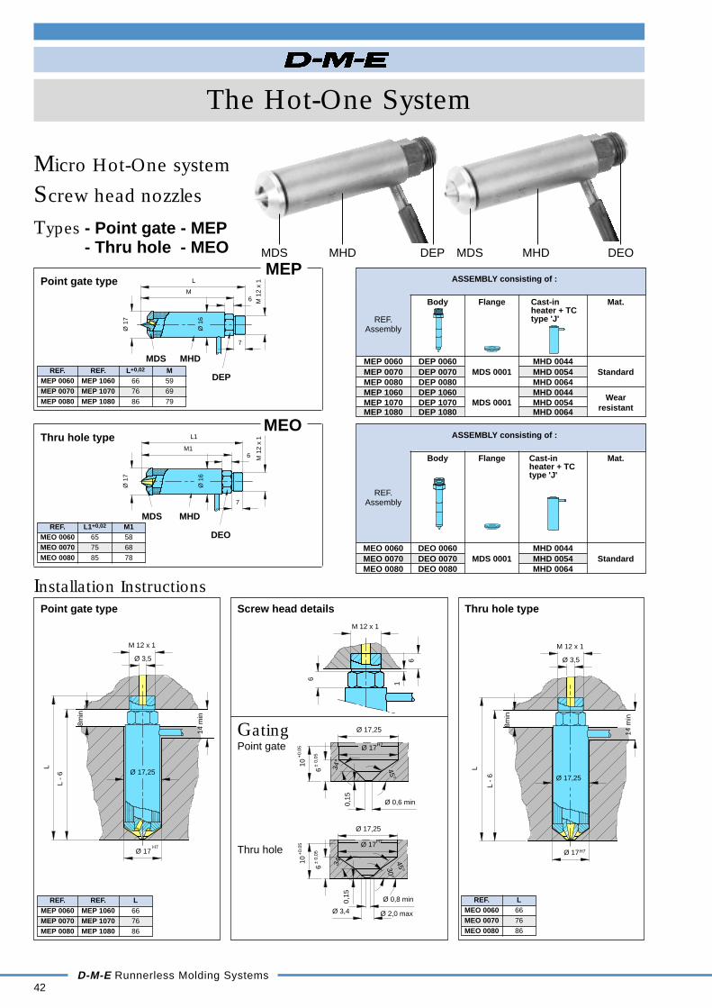
Screw head nozzles
Micro Hot-One system
MEP
REF. REF. L+0,02 MMEP 0060 MEP 1060 66 59MEP 0070 MEP 1070 76 69MEP 0080 MEP 1080 86 79
Point gate type
MEO
REF. L1+0,02 M1MEO 0060 65 58MEO 0070 75 68MEO 0080 85 78
Thru hole type
Installation InstructionsPoint gate type
REF. REF. LMEP 0060 MEP 1060 66MEP 0070 MEP 1070 76MEP 0080 MEP 1080 86
Thru hole type
REF. LMEO 0060 66MEO 0070 76MEO 0080 86
Screw head details
GatingPoint gate
Thru hole
Body Flange Cast-in Mat.heater + TCtype 'J'
ASSEMBLY consisting of :
REF.Assembly
MEP 0060 DEP 0060 MHD 0044MEP 0070 DEP 0070 MDS 0001 MHD 0054 StandardMEP 0080 DEP 0080 MHD 0064MEP 1060 DEP 1060 MHD 0044MEP 1070 DEP 1070 MDS 0001 MHD 0054
Wear
MEP 1080 DEP 1080 MHD 0064 resistant
Types - Point gate - MEP- Thru hole - MEO
Body Flange Cast-in Mat.heater + TCtype 'J'
ASSEMBLY consisting of :
REF.Assembly
MEO 0060 DEO 0060 MHD 0044MEO 0070 DEO 0070 MDS 0001 MHD 0054 StandardMEO 0080 DEO 0080 MHD 0064
L -
6
H7
14 m
in
L
8min
Ø 3,5
M 12 x 1
Ø 17
Ø 17,25
MDS MHD DEP MDS MHD DEO
+0.
05
± 0
,05
+0.
05
± 0
,05
H7
H7
45°34°
0,15
10
30°
6
Ø 3,4
Ø 0,8 min
Ø 2,0 max
Ø 17,25
Ø 17
Ø 0,6 min0,15
34°
45°
Ø 17
Ø 17,25
6
10
H7
H7Ø 17
Ø 17,25
22A
2 Ø 22 3.5
min
H7
H7
Ø 222
A22
Ø 17,25
Ø 17
3.5
min
MDS
DSP
MHD
MSR
Ø 1
6
A
Ø 1
7
22Ø
21
Ø 2
2
The Hot-One System
D-M-E Runnerless Molding Systems43
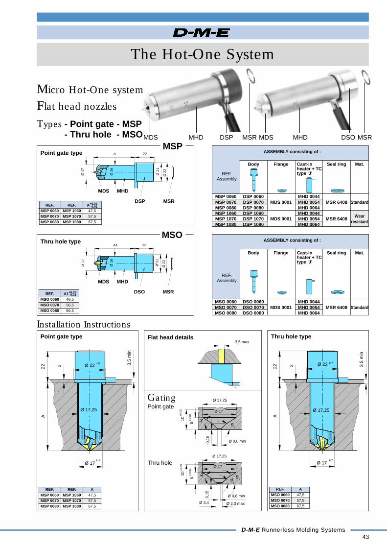
Flat head nozzles
Micro Hot-One system
MSP
REF. REF. A+0,03
MSP 0060 MSP 1060 47,5MSP 0070 MSP 1070 57,5MSP 0080 MSP 1080 67,5
Point gate type
MSO
REF. A1+0,03
MSO 0060 46,5MSO 0070 56,5MSO 0080 66,5
Thru hole type
Installation InstructionsPoint gate type
REF. REF. AMSP 0060 MSP 1060 47,5MSP 0070 MSP 1070 57,5MSP 0080 MSP 1080 67,5
Thru hole type
REF. AMSO 0060 47,5MSO 0070 57,5MSO 0080 67,5
Body Flange Cast-in Seal ring Mat.heater + TCtype 'J'
ASSEMBLY consisting of :
REF.Assembly
Types - Point gate - MSP- Thru hole - MSO
MSP 0060 DSP 0060 MHD 0044MSP 0070 DSP 0070 MDS 0001 MHD 0054 MSR 6408 StandardMSP 0080 DSP 0080 MHD 0064MSP 1060 DSP 1060 MHD 0044MSP 1070 DSP 1070 MDS 0001 MHD 0054 MSR 6408
Wear
MSP 1080 DSP 1080 MHD 0064resistant
Body Flange Cast-in Seal ring Mat.heater + TCtype 'J'
ASSEMBLY consisting of :
REF.Assembly
MSO 0060 DSO 0060 MHD 0044MSO 0070 DSO 0070 MDS 0001 MHD 0054 MSR 6408 StandardMSO 0080 DSO 0080 MHD 0064
Flat head details
GatingPoint gate
Thru hole
3.5 max
DSO MSR
MHDMDS
Ø 1
6
Ø 1
7
A1 22
Ø 2
2
Ø 2
1
-0,01
-0,01
MDS MHD DSP MSR MDS MHD DSO MSR

44D-M-E Runnerless Molding Systems
MDS
DEO
MHD
M 1
2 x
1
L1
M16
7
Ø 1
7
Ø 1
6
The Hot-One System
Body Support Support Insula- Seal Band TCblocks blocks ting ring heater Type 'J'
ring
Multiple gate nozzles
Types - MGS
SUB-ASSEMBLY consisting of :
REF.Sub-
Assembly
Micro Hot-One system
The Multiple gate nozzle developed by D-M-Eincreases the potential number of cavities for a moldby allowing up to six cavities per nozzle. It providesprecise temperature control resulting in an excellenttemperature balance between the individual gates.
MGSMultiple gate nozzles
The Multiple gate nozzle fits into a small mold base,cutting equipment cost and reducing the size of theinjection machine required. The nozzle tips are madeof a wear resistant material that provides high thermalconductivity and long service life.
REF. A B C DMGS 3802 70 38 20 54/3MGS 3804 70 38 20 54/3MGS 6003 90 60 40 72/3MGS 6006 90 60 40 72/3
How to orderTo order a complete Multiple gate nozzle:1. Select one of the available Sub-Assembly reference
numbers.2. Select the reference number of the corresponding Point
gate or Thru hole tip of the Screw head type.3. Both reference numbers as listed under 1. and 2. are
required to get the right delivery.
Remarks: For single application, use the insulating ringWTO 3000. Radius to be made by customer. For applica-tions under a manifold, use the seal ring EHR 1150.
Tips for Multiple gate nozzlesMEP
REF. Assembly L+0,02 MMEP 0060 MEP 1060 66 59MEP 0070 MEP 1070 76 69MEP 0080 MEP 1080 86 79
Screw head nozzle - point gate type
MEO
REF. Assembly L1+0,02 M1MEO 0060 65 58MEO 0070 75 68MEO 0080 85 78
Screw head nozzle - thru hole type
MEO
MEP
D/3
ECB
WTOECB
TCM
EHR
BHF
60°
60°
Ø 60
90°
Ø 38
10
L1
Ø 16
Ø 36
Ø 25
C
6
A
B
10 *
6
45L
51
4 tips 6 tips
* min. 6 mm
MDS MHD
DEP
M 1
2 x
1
7
6
L
Ø 1
7
M
Ø 1
6
MGS 3802 ECB 0501 BHF 3870MGS 3804 ECB 0500 WTO 3000 EHR 1150 TCM 0003MGS 6003 ECB 0502 BHF 3890MGS 6006

60°
60°90°
Ø 38 Ø 60
50
L-6
L+45
20 m
in
8,5
Ø P
Ø C
L -1
6 m
in
51
30 m
in
The Hot-One System
D-M-E Runnerless Molding Systems45
P C H70 105 L + 4590 125 L + 45
Installation Instructions - Tips for Multiple gate nozzles - MEP - MEO
Screw head nozzlesPoint gate type
REF. REF. LMEP 0060 MEP 1060 66MEP 0070 MEP 1070 76MEP 0080 MEP 1080 86
Screw head nozzlesThru hole type
REF. LMEO 0060 66MEO 0070 76MEO 0080 86
GatingPoint gate
Thru hole
Micro Hot-One systemInstallation Instructions - Multiple gate nozzles - MGS
Screw head nozzles
H7
10 n
om. (
6 m
in.)
14 m
in
L
L -
6
Ø 17
Ø 17,25
H7
10 n
om. (
6 m
in.)
14 m
in
Ø 17,25
Ø 17
L -
6
L
+0.
05
± 0
,05
H7
10
Ø 0,6 min
6
0,15
34°
45°
Ø 17
Ø 17,25 Min.
+0.
05
± 0
,05
H7
Ø 2,0 max
45°34°
0,15
10
Ø 3,4
Ø 0,8 min
Ø 17,25 Min.
Ø 17
30°
6
ESR
EEPERP
ECB
MGS
DR HR DI WTO BHA
ECB

Spare parts for nozzlesTo be ordered
separately
Spare Parts - MEP - MEO - MSP - MSO - MGS
Spare parts for nozzles
46D-M-E Runnerless Molding Systems
REF. REF. REF. REF. REF. REF. REF. REF.MEP DEP MHD MDS MSR Mat. ASF
MEP 0060 DEP 0060 MHD 0044MEP 0070 DEP 0070 MHD 0054 MDS 0001 StandardMEP 0080 DEP 0080 MHD 0064MEP 1060 DEP 1060 MHD 0044 WearMEP 1070 DEP 1070 MHD 0054 MDS 0001 resistantMEP 1080 DEP 1080 MHD 0064
MEO DEO MHD MDS MSR Mat. ASFMEO 0060 DEO 0060 MHD 0044MEO 0070 DEO 0070 MHD 0054 MDS 0001 StandardMEO 0080 DEO 0080 MHD 0064
MSP DSP MHD MDS MSR Mat. ASFMSP 0060 DSP 0060 MHD 0044MSP 0070 DSP 0070 MHD 0054 MDS 0001 MSR 6408 Standard ASF 0218MSP 0080 DSP 0080 MHD 0064MSP 1060 DSP 1060 MHD 0044 WearMSP 1070 DSP 1070 MHD 0054 MDS 0001 MSR 6408 resistant ASF 0218MSP 1080 DSP 1080 MHD 0064
MSO DSO MHD MDS MSR Mat. ASFMSO 0060 DSO 0060 MHD 0044MSO 0070 DSO 0070 MHD 0054 MDS 0001 MSR 6408 Standard ASF 0218MSO 0080 DSO 0080 MHD 0064
The Hot-One System
Micro Hot-One system
Body Cast-in heater Flange Seal ring MaterialDEP DEO TC type 'J'
DSP DSO
Screw headnozzlesPoint gate type
Screw headnozzlesThru hole type
Flat headnozzlesPoint gate type
Flat headnozzlesThru hole type
Multiplegate nozzles
REF. REF. REF. REF. REF. REF. REF. REF. REF.MGS WTO ECB ECB BHF TCM EHR MEP
MGS 3802 ECB 0501 BHF 3870 MEP 0060MGS 3804
WTO 3000ECB 0501
ECB 0500BHF 3870 MEP 0070
MGS 6003 ECB 0502 BHF 3890TCM 0003 EHR 1150
MEP 0080MGS 6006 ECB 0502 BHF 3890 MEP 1060
MEP 1070MEP 1080
MEOMEO 0060MEO 0070MEO 0080
To be orderedseparately
Spacer ring
Body Insulating Support Support Band heater Thermo- Seal ring Nozzlering block (lower) block (upper) couple Assembly
Type 'J'MEP MEO
QuickSelection
Chart
MicroHot-OneNozzles
Nozzles

A1A
L1L
ASF
2
Ø 21.8
Ø 17.25
3 m
in.
The Hot-One System
D-M-E Runnerless Molding Systems47
Nozzles
Micro Hot-One system
DEP
REF. L+0,02 For Mat.DEP 0060 66 MEP 0060DEP 0070 76 MEP 0070 StandardDEP 0080 86 MEP 0080DEP 1060 66 MEP 1060DEP 1070 76 MEP 1070 Wear resistantDEP 1080 86 MEP 1080
Body-Screw head nozzle, point gate type
Spare Parts - MEP - MEO - MSP - MSO - MGS
DSP
REF. A+0,03 For Mat.DSP 0060 47,5 MSP 0060DSP 0070 57,5 MSP 0070 StandardDSP 0080 67,5 MSP 0080DSP 1060 47,5 MSP 1060DSP 1070 57,5 MSP 1070 Wear resistantDSP 1080 67,5 MSP 1080
Body-Flat head nozzle, point gate type
MDS
REF. ForMSP - MSO
MDS 0001MEP - MEO
Flange
DEO
REF. L1+0,02 ForDEO 0060 65 MEO 0060DEO 0070 75 MEO 0070DEO 0080 85 MEO 0080
Body-Screw head nozzle, thru hole type
DSO
REF. A1+0,03 ForDSO 0060 46,5 MSO 0060DSO 0070 56,5 MSO 0070DSO 0080 66,5 MSO 0080
Body-Flat head nozzle, thru hole type
ASF
REF. ForASF 0218 MSP - MSO
Spacer ring for Flat head nozzles
Ø 17
-0,01
-0,01
Installation
48D-M-E Runnerless Molding Systems
The Hot-One System
Nozzles
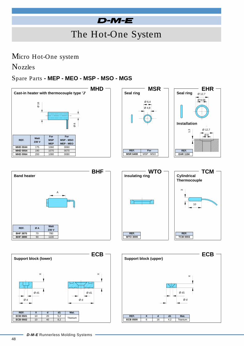
Micro Hot-One system
MHD
For ForREF.
WattMSP MSP - MSO
230 VMEP MEP - MEO
MHD 0044 175 1060 0060MHD 0054 190 1070 0070MHD 0064 200 1080 0080
Cast-in heater with thermocouple type 'J'
BHF
REF. Ø AWatt230 V
BHF 3870 70 780BHF 3890 90 1100
Band heater
ECB
REF. X d d1 Mat.ECB 0501 10 20 5,2ECB 0502 10 40 8,2
Titanium
Support block (lower)
MSR
REF. ForMSR 6408 MSP - MSO
Seal ring
WTO
REF.WTO 3000
Insulating ring
ECBSupport block (upper)
REF. X d d1 Mat.ECB 0500 6 16 4,2 Titanium
TCM
REF.TCM 0003
EHR
REF.EHR 1150
Spare Parts - MEP - MEO - MSP - MSO - MGS
CylindricalThermocouple
Seal ring
Ø 8
Ø 1
6
XX
Ø d
Ø d1
Ø d
Ø d1
AX
Ø d
Ø d1
10
3
Ø 6,4
Ø 4,8
1,3 Ø 12,7
Ø 8
Ø 12,7
Ø 9,56
Installation

The Hot-One System
D-M-E Runnerless Molding Systems49
Machining Instructions
Standard Hot-One system
Manifold, Nozzle plate, Mold plate gate machining dimensions for:
Conventional and High performance Hot-One nozzles, Gate Mate 4TM, Mini Gate Mate.
Locating rings EHLREF. Ø F Ø G Ø H Ø J
EHL 0252 EX 101,5 84,1 75 64EHL 0253 EX 139,7 118 100 95
Heated adaptersBHA-M20 BHA-M24
M 20 x 1,5 24 x 1,5A±0,02 14,8 18ØB±0,2 24 27ØC±0,5 50 60L±1min 75 80
NozzlesREF. K ØM ØN250 40 38 30375 52 50 41625 78 76 54
Gate Mate 4TM 40 38 32Mini Gate Mate 40 38,1 28,5
Height = riser padsspacer ring and manifold
Cooling linesRec
omm
ende
d
Machining dimensions for locating ring
Hei
ght o
f spa
cer
ring
and
cent
er s
uppo
rt b
lock
min
6,0
Man
ifold
hei
ght
Riser pad heightmin 6.0
Cooling lines
EHL
25,4
6,35 min
K
M
N
16
A+ ˘A
36
3,0
min3,
0
8,5
(2
piec
es)
6
M8
F
G
H
J
Gate Mate 4TM
Conventional andHigh performancenozzle
Sprue and Ring gate
∆A = A x (11,4 x 10⁻⁶) x ∆T(∆T = T max . °C - 20 °C)
REF. N L T250 30 2 12,5375 40 2 19625 54 4 25
REF. AGMB 0150 EX 50,8GMB 0151 EX 63,5GMB 0152 EX 76,2GMB 0153 EX 88,9GMB 0154 EX 101,6GMB 0155 EX 127,0GMB 0156 EX 152,4
Gate Mate 4TM
∆A = A x αc x 10-6 x ∆T(αc = 16,8 - 0,026 x A)(∆T = nozzle set point - 20°C)(not valid for GMT 0300)
4 min
Conventional andHigh performancenozzle
Extended sprue gate
∆A = A x (11,4 x 10⁻⁶) x ∆T(∆T = T max . °C - 20 °C)
±1
+0,
1+
0,5
-0
H7
Machining dimensions for heated adapter
45°
32
16 m
in
Ø 71
M8 x 4
Ø 90
C
B
M
Min
52,
5
A
25
10
L
A +
A
H6
R9,5
R3
Ø 19
30°
F*
=
20
Max 4.5
R5
Min 1
0.15 0.
8
80°
90°
2
R 3.2
Ø 15,87
30°
30°
10.2
Ø 0,8 min
90°
0,1
max
cyl
.
TH6
A +
A
R d
~0.
5
4.5
2.5
0,15
30°
H6
L
A +
AN
T
30°
Mini Gate Mate
∆A = A x (11,4 x 10⁻⁶) x ∆t(∆T = T max °C - 20°C)
Conventional andHigh performancenozzle
Point gate
∆A = A x (11,4 x 10⁻⁶) x ∆T(∆T = T max . °C - 20 °C)
REF. Ø d ØT R250 1,5-3,0 9,5 3,2375 2,0-4,0 12,5 4,7

50D-M-E Runnerless Molding Systems
The Hot-One System
Machining Instructions
Micro Hot-One system
Manifold, Nozzle plate, Mold plate gate machining dimensions for:
Micro Hot-One nozzles and Multiple gate nozzles.
Micro Hot-One nozzles
Screw head style
Micro Hot-One nozzles
Flat head style
P C H70 105 L + 4590 125 L + 45
H7 H7
14 m
in
Ø 3,5
M 12 x 1
14 m
in
Ø 17,25
Ø 17
6min
L -6
LL
L -6
6min
Ø 3,5
M 12 x 1
Ø 17
Ø 17,25
REF. REF. REF. LMEP 0060 MEP 1060 MEO 0060 66MEP 0070 MEP 1070 MEO 0070 76MEP 0080 MEP 1080 MEO 0080 86
+0.
05
± 0
,05
+0.
05
± 0
,05
H7H7
Ø 2,0 max
45°34°
10
0,15
10
Ø 3,4
Ø 0,8 min
Ø 17,25
Ø 17
30°
6
Ø 0,6 min
6
0,15
34°
45°
Ø 17
Ø 17,25
Multiple gate nozzles with Screw head nozzles
60°
60°90°
Ø 38 Ø 60
Gating GatingPoint gate type Thru hole type
Gating GatingPoint gate type Thru hole type
+0.
05
± 0
,05
+0.
05
± 0
,05
H7H7
Ø 2,0 max
45°34°
10
0,15
10
Ø 3,4
Ø 0,8 min
Ø 17,25
Ø 17
30°
6
Ø 0,6 min
6
0,15
34°
45°
Ø 17
Ø 17,25
REF. REF. REF. AMSP 0060 MSP 1060 MSO 0060 47,5MSP 0070 MSP 1070 MSO 0070 57,5MSP 0080 MSP 1080 MSO 0080 67,5
50
L-6
L+45
20 m
in
8,5
Ø P
Ø C
L -1
6 m
in
51
30 m
in
H7H7
H7H7
3.5
min
Ø 17
Ø 17,25
22A
2 Ø 22 3.5
min
Ø 222
A22
Ø 17,25
Ø 17

D-M-E Runnerless Molding Systems51
The Hot-One System
The Hot-One conceptOsco® Valve Gate systemThe Osco® Valve Gate system from D-M-E represents the ultimate in part cosmetics,knit line control and part quality over the widest spectrum of applications includinglarge, multi-gated parts and family molds with unbalanced flow.
This superiority can be attributed to the floating hydraulic cylinder/valve pinassembly which provides positive indivual gate shut-off
The key to the system's operation is the method to open and close each gate. In theopening cycle, delay timers activated by the machine's high-pressure clamp circuitallow injection pressure to build. At a determined time, hydraulic cylinders retractthe valve piston/pin assembly at each gate, permitting material to flow into the moldcavity at an increased velocity. Secondary individual timers positively close eachgate after the proper pre-set fill time, eliminating overpacking while allowing othergates to remain open until their optimum fill time is reached.
Two nozzle styles are available: the Full-Body nozzle is suggested when a circularnozzle mark is allowed, the Bodyless nozzle offers impeccable cosmetics, feedingdirectly into the part.
Manifold AncillariesHeated nozzle adapters
EHN
EHL
p. 66
HRDR
DIWTO
BHA
p. 67
Manifold AncillariesRiser pads (no view)
ERP
p. 72
Spacer rings
ESRp. 72
Support blocks
ECBp. 72
Nozzles & AccessoriesOsco® Valve Gate
FBVVG-VPR
VG-HCA
VGPBRPBEHR
FBV
SCH
PGVG-FBT
p. 52/53
BLVVG-VPR
VG-HCA
VPPBRPBEHR
BLV
SCH
PGVG-BLT
p. 54/55
Manifold AncillariesEnd caps
EHM
GZ EEP EDR p. 73
EHM
EEP p. 73
Manifold AncillariesCartridge heaters
CHR
CHS
ECH
EHP
Tubular
p. 68/70
Thermocouples (no view)
ETC
ETC
ETC
TCM p.71/72

Bo
dy
Sea
l rin
g
Sq
uar
e co
il h
eate
r
wit
h T
C t
ype
'J'
Pin
gu
ide
Val
ve p
in
Val
ve p
in r
etai
ner
Fu
ll-B
od
y ti
p
Pin
bu
shin
g r
etai
ner
Man
ifo
ld p
in b
ush
ing
Hyd
rau
lic c
ylin
der
Bo
dy
Sea
l rin
g
Sq
uar
e co
il h
eate
r
wit
h T
C t
ype
'J'
Pin
gu
ide
Val
ve p
in
Val
ve p
in r
etai
ner
Fu
ll-B
od
y ti
p
Pin
bu
shin
g r
etai
ner
Man
ifo
ld p
in b
ush
ing
Hyd
rau
lic c
ylin
der
FBV
52
The Hot-One System
D-M-E Runnerless Molding Systems
Full-Body nozzles - FBV
OSCO® Valve Gate system
The Full-Body Valve Gate nozzle is designed to feedthe part or runner and is ideal for use where thenozzle circular mark is allowed. It is supplied with athermocouple controlled spiral heater that distributesheat throughout the nozzle uniformly.
The unique removable tip construction provides maximumflexibility. There is no need to replace the whole unit, yetit has longer life than conventional floating pin units,which causes misaligned pin/orifice engagement.
REF. A REF. A
FBV 520 50,80 FBV 540 101,60FBV 525 63,50 FBV 550 127,00FBV 530 76,20 FBV 560 152,40FBV 535 88,90
FBV
T L O
9,52 2,2912,70 3,17
min. 1,27
19,05 4,95max. 2,03
ASSEMBLY consisting of :
REF.
Assem-bly
FBV 520 SCH 0081FBV 525 SCH 0082FBV 530 SCH 0083FBV 535 EHR 0154 SCH 0084 PG 50 VP 50x14 VG 50-VPR VG 50-FBT PBR 50 PB 50 VG 50-HCAFBV 540 SCH 0085FBV 550 SCH 0086FBV 560 SCH 0087
Bo
dy
Sea
l rin
g
Sq
uar
e co
il h
eate
r
wit
h T
C t
ype
'J'
Pin
gu
ide
Val
ve p
in
Val
ve p
in r
etai
ner
Fu
ll-B
od
y ti
p
Pin
bu
shin
g r
etai
ner
Man
ifo
ld p
in b
ush
ing
Hyd
rau
lic c
ylin
der
ASSEMBLY consisting of :
REF.
Assem-bly
FBV 1020 SCH 0088FBV 1025 SCH 0089FBV 1030 SCH 0090FBV 1035
EHR 0155SCH 0091
PG 100 VP 100x14 VG 100-VPR VG 100-FBT PBR 100 PB 100 VG 100-HCAFBV 1040 SCH 0092FBV 1050 SCH 0093FBV 1060 SCH 0094FBV 1070 SCH 0095
ASSEMBLY consisting of :
REF.
Assem-bly
FBV 2040 SCH 0096FBV 2050 SCH 0097FBV 2060 SCH 0098FBV 2070 EHR 0156 SCH 0099 PG 200 VP 200x14 VG 200-VPR VG 200-FBT PBR 200 PB 200 VG 200-HCAFBV 2080 SCH 0100FBV 2090 SCH 0101FBV 2100 SCH 0102
T L O
12,70 3,1719,05 4,95
min. 2,03
25,40 9,11max.3,81
T L O
12,70 3,1719,05 4,75
min. 3,81
25,40 9,11max. 6,35
Series 50
REF. A REF. A
FBV 1020 50,80 FBV 1040 101,60FBV 1025 63,50 FBV 1050 127,00FBV 1030 76,20 FBV 1060 152,40FBV 1035 88,90 FBV 1070 177,8
Series 100
FBV
REF. A REF. A
FBV 2040 101,60 FBV 2080 203,20FBV 2050 127,00 FBV 2090 228,60FBV 2060 152,40 FBV 2100 254,00FBV 2070 177,80
Series 200
VG-FBT FBV VP
VG-FBT PG SCH PBRPB VG-HCA VG-VPRFBV EHRVP
Ø3.
2
O
30°L
Ø38
.1
A 25.4
11.0
Ø24
.5
Ø8
T
VP VG-VPRVG-HCAPBRPBVG-FBT PG SCH FBV EHR
28.58
O
30°L Ø
4.75
T
Ø11
Ø38
A
14.5
Ø50
.8
VG-FBT PG SCH EHRFBVVP PBRPB VG-HCA VG-VPR
Ø7.
9
30°L
O
Ø15
.9
A
Ø45
T
16.5
38.1
Ø76
.2

Ø76.2
66 nom.
(A +
167
.6 m
in.)
57.5 min.
-0.0
5+
0
-0+0.
02
-0.05+0.05
-0.07
0.8x45°
0.5x45°max
+0.03
0.5 x 45°
+0.05+0.02
+0.02+0.05
A +
176
.1 n
om.6
min
.
6 min.
66min.
38.1
A
3.0
Ø78
Ø76.2
100
1630
30°
T
2.0
125
9.7
22.1
Ø104.8
Ø114.3
57.5
min
.
25
Ø50
+0.
02-0
.02
-0.0
2+
0
48 min.
(A +
125
.4 m
in.)
-0.05+0.05
-0.07+0.03
0.5x45°max
0.8x45°
0.5 x 45°
+0.04+0.02
+0.02+0.04A
+ 1
33.4
nom
.
56 nom.
6 min.
46 min.
25.4
A6 m
in.
Ø38.1
Ø38.1
Ø40
70
16
3.0
30°
T
105
25
2.0
32
6.5
34.8
Ø39.7
Ø46
48 m
in.
Ø28.5
56 nom.
(A +
141
.6 m
in.)
51 min.
-0+0.
02
0.5x45°max
0.8x45°
-0.02+0.08
-0.07+0.03
+0.
02-0
.02
+0.02+0.05
0.5 x 45°
+0.02+0.05
6 m
in.
A +
146
.6 n
om.
6 min.
56 min.
28.6
A3.
0
Ø54
Ø50.8
80
16
Ø50.8
2.0
T
30°
30
125
25
12.8
5
Ø98.4
Ø92.1
51 m
in.
25.2
5
Ø42
D-M-E Runnerless Molding Systems53
The Hot-One System
Osco® Valve Gate systemInstallation Instructions - Full-Body nozzles - FBV
How to orderTo order a complete Osco® Valve Gate nozzle:1. Select one of the available reference numbers of the
Osco® Valve Gate nozzles - Full-Body type.
2. Specify the T-diameter of the tip.3. Specify the O-diameter, which can be of any size
between min. and max.
Hydraulic cylinder Hydraulic cylinder
FBV
Hydraulic cylinder
Series 200FBV
Series 100FBV
Series 50

Bo
dy
Sea
l rin
g
Sq
uar
e co
il h
eate
r
wit
h T
C t
ype'
J'
Pin
gu
ide
Val
ve p
in
Val
ve p
in r
etai
ner
Bo
dyl
ess
tip
Pin
bu
shin
g r
etai
ner
Man
ifo
ld p
in b
ush
ing
Hyd
rau
lic c
ylin
der
Bo
dy
Sea
l rin
g
Sq
uar
e co
il h
eate
r
wit
h T
C t
ype'
J'
Pin
gu
ide
Val
ve p
in
Val
ve p
in r
etai
ner
Bo
dyl
ess
tip
Pin
bu
shin
g r
etai
ner
Man
ifo
ld p
in b
ush
ing
Hyd
rau
lic c
ylin
der
Bo
dy
Sea
l rin
g
Sq
uar
e co
il h
eate
r
wit
h T
C t
ype'
J'
Pin
gu
ide
Val
ve p
in
Val
ve p
in r
etai
ner
Bo
dyl
ess
tip
Pin
bu
shin
g r
etai
ner
Man
ifold
pin
bus
hing
Hyd
rau
lic c
ylin
der
54
The Hot-One System
D-M-E Runnerless Molding Systems
Bodyless nozzles - BLV
OSCO® Valve Gate system
The Bodyless type nozzle is designed to feed directly in-to the molded part and to be used where the typical cir-cular mark of the conventional nozzle is not allowed. It issupplied with a thermocouple controlled spiral heater thatdistributes heat throughout the nozzle uniformly.
The nozzle is equipped with a pin guide to assureconcentricity within the valve pin and the tapered ope-ning, eliminating the typical wear at the opening. Noneed for hardened cavity steel.
O
min. 1,27max. 2,03
ASSEMBLY consisting of :
REF.
Assem-bly
BLV 520 SCH 0081BLV 525 SCH 0082BLV 530 SCH 0083BLV 535 EHR 0154 SCH 0084 PG 50 VP 50x14 VG 50-VPR VG 50-BLT PBR 50 PB 50 VG 50-HCABLV 540 SCH 0085BLV 550 SCH 0086BLV 560 SCH 0087
ASSEMBLY consisting of :
REF.
Assem-bly
BLV 1020 SCH 0088BLV 1025 SCH 0089BLV 1030 SCH 0090BLV 1035
EHR 0155SCH 0091
PG 100 VP 100x14 VG 100-VPR VG 100-BLT PBR 100 PB 100 VG 100-HCABLV 1040 SCH 0092BLV 1050 SCH 0093BLV 1060 SCH 0094BLV 1070 SCH 0095
ASSEMBLY consisting of :
REF.
Assem-bly
BLV 2040 SCH 0096BLV 2050 SCH 0097BLV 2060 SCH 0098BLV 2070 EHR 0156 SCH 0099 PG 200 VP 200x14 VG 200-VPR VG 200-BLT PBR 200 PB 200 VG 200-HCABLV 2080 SCH 0100BLV 2090 SCH 0101BLV 2100 SCH 0102
O
min. 2,03max.3,81
O
min. 3,81max. 6,35
BLV
REF. A REF. ABLV 520 50,80 BLV 540 101,60BLV 525 63,50 BLV 550 127,00BLV 530 76,20 BLV 560 152,40BLV 535 88,90
BLVSeries 50
REF. A REF. ABLV 1020 50,80 BLV 1040 101,60BLV 1025 63,50 BLV 1050 127,00BLV 1030 76,20 BLV 1060 152,40BLV 1035 88,90 BLV 1070 177,80
Series 100
BLV
REF. A REF. ABLV 2040 101,60 BLV 2080 203,20BLV 2050 127,00 BLV 2090 228,60BLV 2060 152,40 BLV 2100 254,00BLV 2070 177,80
Series 200
VG-BLT BLV VP
VG-BLT PG SCH PBRPB VG-HCA VG-VPRBLV EHRVP
O
Ø3.
2
Ø38
.1
A 25.4
11.0
Ø24
.5
Ø8
Ø 1
2.7
28,58
VP VG-VPRVG-HCAPBRPBVG-BLT PG SCH BLV EHR
O
Ø4.
75
Ø15
.9
Ø11
Ø38
A
14.5
Ø50
.8
VG-BLT PG SCH EHRBLVVP PBRPB VG-HCA VG-VPR
O
Ø7.
9
Ø15
.9
A
Ø45Ø22
.2
16.5
38.1
Ø76
.2
D-M-E Runnerless Molding Systems55
The Hot-One System
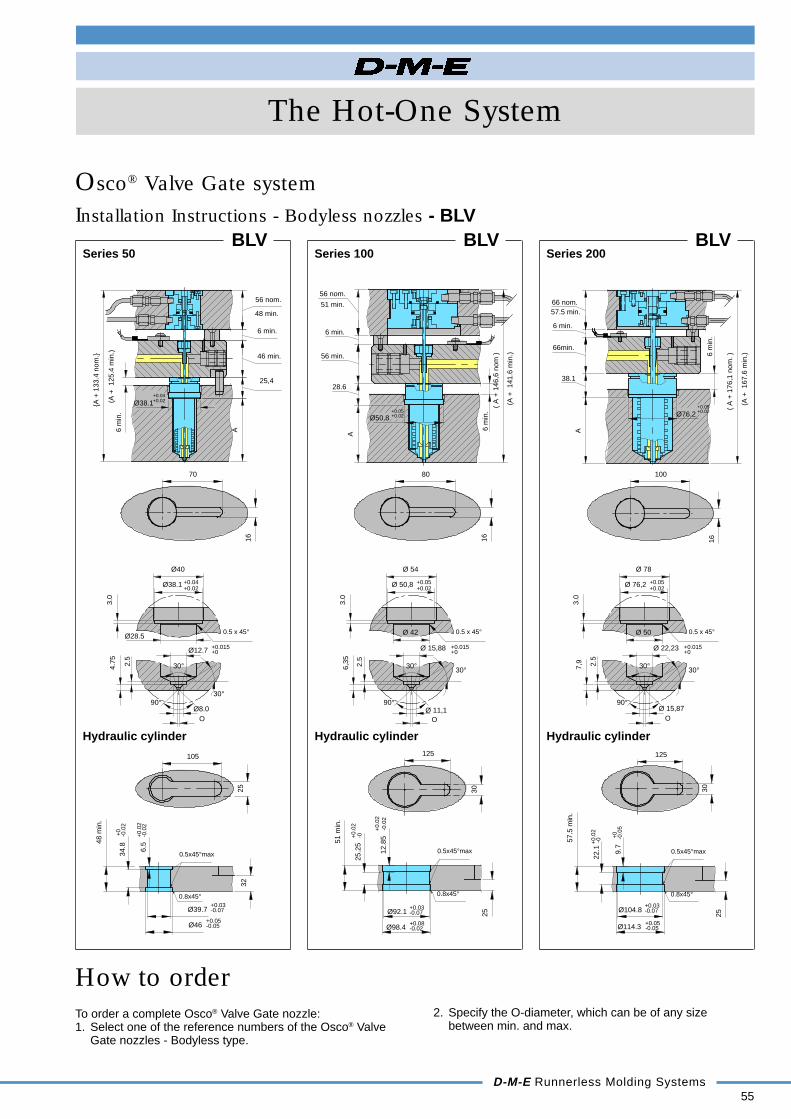
Osco® Valve Gate systemInstallation Instructions - Bodyless nozzles - BLV
How to orderTo order a complete Osco® Valve Gate nozzle:1. Select one of the reference numbers of the Osco® Valve
Gate nozzles - Bodyless type.
2. Specify the O-diameter, which can be of any sizebetween min. and max.
Hydraulic cylinder Hydraulic cylinder Hydraulic cylinder
BLVSeries 200
BLVSeries 100
BLVSeries 50
48 min.
(A +
125
.4 m
in.)
+0.
02-0
.02
-0.05+0.05
-0.07+0.03
-0.0
2+
0
0.5x45°max
0.8x45°
+0.02+0.04
+0.015+0
0.5 x 45°
+0.04+0.02
25,4
3.0
Ø40
Ø38.1
30°
4.75
Ø12.7
2.5
O
90°Ø8.0
30°
Ø28.5
A +
133
.4 n
om.
56 nom.
6 min.
46 min.
A6 m
in.
Ø38.1
70
16
105
2532
6.5
34.8
Ø39.7
Ø46
48 m
in.
56 nom.
(A +
141
.6 m
in.)
51 min.
+0.
02
-0.02+0.08
-0.07+0.03
+0.
02-0
.02
-0
0.5x45°max
0.8x45°
+0.02+0.05
+0.02+0.05
0.5 x 45°
+0+0.015
Ø 42
30°
Ø 11,190°
O
2.5
Ø 15,88
6,35
30°
Ø 50,8
Ø 54
3.0
6 m
in.
( A
+ 1
46,6
nom
)
6 min.
56 min.
28.6
A
8016
Ø50.8
30
125
25
12.8
5
Ø98.4
Ø92.1
51 m
in.
25.2
5
Ø76.2
66 nom.
(A +
167
.6 m
in.)
57.5 min.
-0.0
5+
0
-0+0.
02
-0.05+0.05
-0.07+0.03
0.8x45°
0.5x45°max
+0.02+0.05
+0.015+0
0.5 x 45°
+0.05+0.02
3.0
Ø 78
Ø 76,2
30°7,9
Ø 22,23
2.5
O
90°Ø 15,87
30°
Ø 50
( A
+ 1
76,1
nom
. )6 m
in.
6 min.
66min.
38.1
A
100
1630
125
9.7
22.1
Ø104.8
Ø114.3
57.5
min
.
25

56
The Hot-One System
D-M-E Runnerless Molding Systems
REF. REF. REF. REF. REF. REF. REF. REF. REF. REF. REF.Full-Body FBV EHR SCH PG VP VG-VPR VG-FBT VG-BLT PBR PB VG-HCAFBV 520 SCH 0081FBV 525 SCH 0082FBV 530 SCH 0083FBV 535 EHR 0154 SCH 0084 PG 50 VP 50X14 VG 50-VPR VG 50-FBT PBR 50 PB 50 VG 50-HCAFBV 540 SCH 0085FBV 550 SCH 0086FBV 560 SCH 0087FBV 1020 SCH 0088FBV 1025 SCH 0089FBV 1030 SCH 0090FBV 1035 SCH 0091FBV 1040
EHR 0155SCH 0092
PG 100 VP 100X14 VP 100-VPR VG 100-FBT PBR 100 PB 100 VG 100-HCA
FBV 1050 SCH 0093FBV 1060 SCH 0094FBV 1070 SCH 0095FBV 2040 SCH 0096FBV 2050 SCH 0097FBV 2060 SCH 0098FBV 2070 EHR 0156 SCH 0099 PG 200 VP 200X14 VG 200-VPR VG 200-FBT PBR 200 PB 200 VG 200-HCAFBV 2080 SCH 0100FBV 2090 SCH 0101FBV 2100 SCH 0102Bodyless BLV EHR SCH PG VP VP-VPR VG-BLT PBR PB VG-HCABLV 520 SCH 0081BLV 525 SCH 0082BLV 530 SCH 0083BLV 535 EHR 0154 SCH 0084 PG 50 VP 50X14 VP 50-VPR VG 50-BLT PBR 50 PB 50 VG 50-HCABLV 540 SCH 0085BLV 550 SCH 0086BLV 560 SCH 0087
BLV 1020 SCH 0088BLV 1025 SCH 0089BLV 1030 SCH 0090BLV 1035 SCH 0091BLV 1040
EHR 0155SCH 0092
PG 100 VP 100X14 VP 100-VPR VG 100-BLT PBR 100 PB 100 VG 100-HCA
BLV 1050 SCH 0093BLV 1060 SCH 0094BLV 1070 SCH 0095BLV 2040 SCH 0096BLV 2050 SCH 0097BLV 2060 SCH 0098BLV 2070 EHR 0156 SCH 0099 PG 200 VP 200X14 VP 200-VPR VG 200-BLT PBR 200 PB 200 VG 200-HCABLV 2080 SCH 0100BLV 2090 SCH 0101BLV 2100 SCH 0102
QuickSelection
Chart
Nozzles
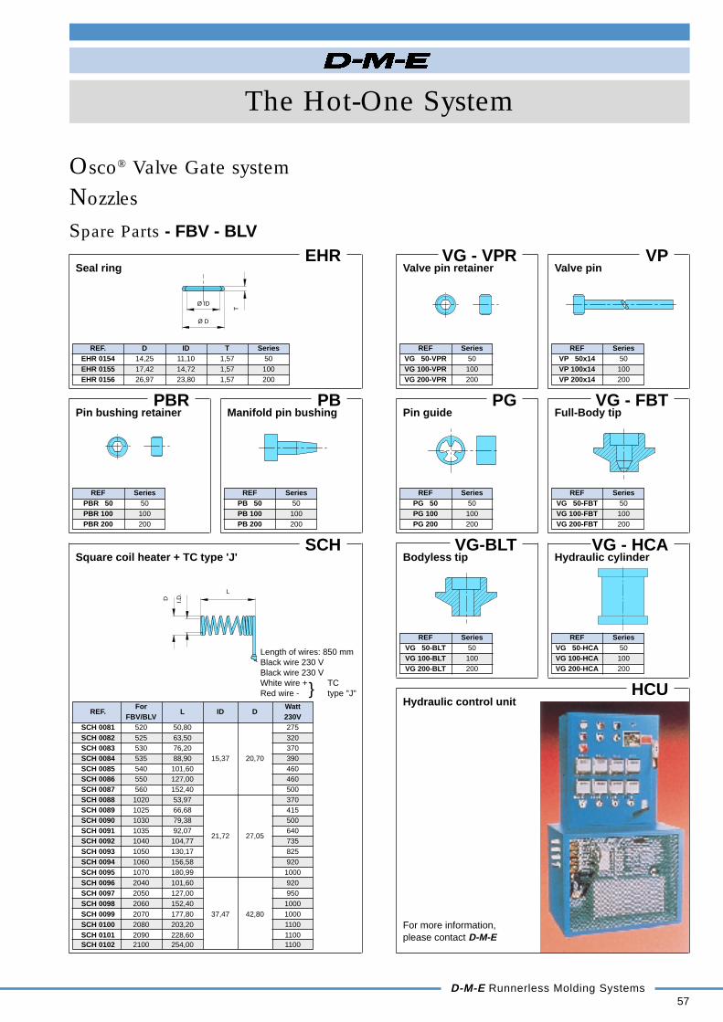
Spare Parts - FBV - BLV
Osco® Valve Gate system
Body Seal ring Square coil Pin guide Valve pin Valve pin Full-Body Bodyless Pin bushing Manifold Hydraulicheater + TC retainer tip tip retainer pin bushing cylindertype 'J'
Series 50
Series 100
Series 200
Series 50
Series 100
Series 200
D-M-E Runnerless Molding Systems57
The Hot-One System
Nozzles
Osco® Valve Gate system
EHR
REF. D ID T SeriesEHR 0154 14,25 11,10 1,57 50EHR 0155 17,42 14,72 1,57 100EHR 0156 26,97 23,80 1,57 200
Seal ringVG - VPR
REF SeriesVG 50-VPR 50VG 100-VPR 100VG 200-VPR 200
Valve pin retainer
Spare Parts - FBV - BLVVP
REF SeriesVP 50x14 50VP 100x14 100VP 200x14 200
PG
REF SeriesPG 50 50PG 100 100PG 200 200
Pin guideVG - FBT
REF SeriesVG 50-FBT 50VG 100-FBT 100VG 200-FBT 200
Valve pin
Full-Body tip
VG-BLT
REF SeriesVG 50-BLT 50VG 100-BLT 100VG 200-BLT 200
Bodyless tipVG - HCA
REF SeriesVG 50-HCA 50VG 100-HCA 100VG 200-HCA 200
Hydraulic cylinder
PB
REF SeriesPB 50 50PB 100 100PB 200 200
Manifold pin bushingPBR
REF SeriesPBR 50 50PBR 100 100PBR 200 200
Pin bushing retainer
HCUHydraulic control unit
For more information,please contact D-M-E
SCH
REF.For
L ID DWatt
FBV/BLV 230VSCH 0081 520 50,80 275SCH 0082 525 63,50 320SCH 0083 530 76,20 370SCH 0084 535 88,90 15,37 20,70 390SCH 0085 540 101,60 460SCH 0086 550 127,00 460SCH 0087 560 152,40 500SCH 0088 1020 53,97 370SCH 0089 1025 66,68 415SCH 0090 1030 79,38 500SCH 0091 1035 92,07 640SCH 0092 1040 104,77
21,72 27,05735
SCH 0093 1050 130,17 825SCH 0094 1060 156,58 920SCH 0095 1070 180,99 1000SCH 0096 2040 101,60 920SCH 0097 2050 127,00 950SCH 0098 2060 152,40 1000SCH 0099 2070 177,80 37,47 42,80 1000SCH 0100 2080 203,20 1100SCH 0101 2090 228,60 1100SCH 0102 2100 254,00 1100
Square coil heater + TC type 'J'
I.D.
D
L
T
Ø D
Ø ID
Length of wires: 850 mmBlack wire 230 VBlack wire 230 VWhite wire + TCRed wire - type "J"

58
The Hot-One System
D-M-E Runnerless Molding Systems
Balanced flow pattern
The Hot-One Manifold
To ensure an equal fill of all cavities, D-M-E's hot-runnerspecialists design most manifolds so that each meltchannel has the same flow length and pressure dropfrom the machine nozzle to the gate.
This ensures natural rheologically balanced flow chan-nels producing the lowest shear stress which results inmaximum productivity and molded product integrity.
D-M-E manifolds are compact and can make use oftubular heaters featuring a uniform temperature profilealong their length.
Each manifold is finished to specific internal diameterrequirements based on shot size, resin type, and pitch.This allows the manifold to more accurately perform toyour specific application.
Terminal mounting boxes:provide the easiest and most economicalmethod of mounting power andthermocouple connectors on the mold.Each box is pre-cut and drilled for quickmounting of the connector to the box, andbox to the mold.Available in 15 and 30 Amp. version for 5,8 and 12 zone main frames. Connectorsto be ordered separately.
Nozzles:a large array of sizes anddesigns, with many differentgating types, different materialsand heater styles. With themodular concept “sub-assemblyplus tip”, hundreds of combina-tions are possible, and all kindsof thermoplastic materials havebeen successfully injected.
Tubular heaters:pressed into place in a precisely machinedgroove on both faces of the manifold, for uniformtemperature, fast warm-up with moderate speci-fic power for improved economy and long heaterlife. The heater groove is kept shallow to allowan excellent heat distribution combined with areduced manifold height. Moreover, the tubularheater is accurately shaped according to thecontour of the manifold.
Reflector plates:reflector plates are used on manifoldsfitted with tubular heaters to reduceheat losses and provide a moreuniform temperature whilst avoidingthe costly operation of casting theheaters in the grooves. Also,replacement is easier in the rareevent of heater failure.
Thermocouples:thermocouples are of the J-type and designed torespond fast to the slightest temperature fluctuation.They are also strategically located to achieve thebest temperature control. The number of thermo-couples and thus of control zones will depend on theshape and on the total installed power, keeping inmind the maximum current allowed per zone (15 A or30 A depending on the control modules) and an evendistribution of the load per phase.
Support blocks:support blocks and riser padsare supplied at choice in steelfor easy machining or intitanium for better insulationand temperature uniformity.
Insulating plate:for reduced heat losses.Asbestos-free, high hotcompressive strength andlonger life.
D-M-E provides upon requestthe fully machined manifoldplate(s), top clamp plate andrisers with the requiredpockets, water lines, wirechannels, and asbestos-freeinsulating board.
Manifolds:quality tool steel adapted to the applica-tion, with balanced flows as required.Streamlined melt channels with carefullymachined bends in the end plugs. Twotypes of heaters are available; cartridgeor tubular, for increased design flexibility,and optimal performance.

D-M-E Runnerless Molding Systems59
The Hot-One System
Package systems
The Hot-One Manifold
D-M-E supplies complete or package manifold systemsincluding all manifold components as well as fully ma-chined top clamp and manifold plates.
D-M-E's package systems are fully assembled and havebeen electrically and mechanically tested to ensureperfect operation.
Standard manifolds
A wide range of standard manifold configurations isavailable.
Manifold recommendations and guidelines
To ensure success of each runnerlessapplication, it is important that molddesigners take the following factors intoconsideration:
1. Selection of proper steel for the nozzle gate area.
2. Proper machining of gate detail to supplied print. (p. 49/50)
3. Proper cooling of the gate area to ensure proper gatevestige and to minimize drool or stringing of the material.
4. Adequate cooling in the nozzle plate, manifold retainerplate and/or support blocks (used to enclose the system),and the top clamp plate.
5. Use of the proper number and size assembly screws.
6. Allowance for adequate system cold clearance to permitlater thermal expansion.
Prior to system assembly, we stronglysuggest you complete the following checksand establish the procedures that willfacilitate proper system assembly :
1. Check the parts list to ensure that all components are ofthe proper part numbers, and that correct quantities aresupplied.
2. Check all supplied heaters for proper resistance in ohms(Ω) and for good resistance to ground conditions by doingthe following:
a. Refer to table supplied in the design package for eachheater used in your system.
b. Note the resistance.
c. Measure each corresponding heater’s resistance anddetermine if they are equivalent.
Guidelines for the use of a manifold block

60
The Hot-One System
D-M-E Runnerless Molding Systems
(Insufficient resistance to ground is defined as areading to ground of 200.000 Ω or less.)
d. Heater resistance should be ± 10 % of listed rating.
e. The electrical resistance is calculated as follows:
R = U2
PR = electrical resistance in Ω (ohm)U = electrical tension in V (Volt)P = electrical power in W (Watt)
3. Manifold:Confirm that the nozzle locations are correct. Use thesupplied manifold drawing to establish the shape of theclearance pocket needed in the manifold retainer plate.
Nozzle Plate
Note the dowel pin locations on your D-M-E suppliedprint and transfer this information to your nozzle platedesign.Provide the adequate number and size water lines aroundnozzle locations and under the manifold shape.Confirm the nozzle plate thickness is as specified on thesupplied drawings. This dimension is important becausea change in plate thickness will affect the total stack up ofthe system and alter the machining dimensions of thenozzle counterbore (C-Bore).Note the nozzle C-Bore depth and transfer this value toyour design. The nozzle plate should be specified in D-M-Esteel 3 or an equivalent. Provide a wire channel to pro-tect and properly route wiring to the terminal box.Do not run wire channels under the manifold, becausemanifold temperatures may cause wire damage.
Note:To prevent rotation during installation, key the nozzles be-fore starting. This procedure will facilitate tip removal forreplacement or clearing of foreign material from the nozz-le tips once the system is assembled. If the cavity contouris machined onto an extended length sprue gate-style tip,the nozzles have to be keyed to prevent rotation.We also recommend that all systems incorporate the useof wire channels to properly route, as well as protect, sys-tem wiring.
Manifold Retainer Plate
The manifold retainer plate should encompass the entiremanifold. Provide adequate number and size water linesaround manifold pocket. The supplied drawing should beused to establish proper clearance around the manifold.Again, proper clearance is critical. Location of the termi-nal mounting box must be determined. Attach the termi-nal mounting box to the mold following the directions gi-ven in the D-M-E 2000 catalog, page 8d-17.A slot (vent) should be cut from the clearance pocket loca-ted toward the bottom side of the manifold retainer plate.(Recommended size: 1.5 mm deep and 25 mm wide.)
The manifold retainer plate should be specified in D-M-Esteel 3 or equivalent. Finally, if necessary, provide properclearance for nozzle heater leads in the underside of themanifold retainer plate.
Top Clamp Plate
Identify locations of upper support pads on the D-M-Esupplied print and transfer this information to your topclamp plate design. These support pads will be mountedto the underside of the top clamp plate. Provide adequa-te number and size water lines over the manifold shape.Transfer the matching machining dimension for the loca-ting ring pocket from the supplied prints. The top clampplate should be specified D-M-E steel 1 or equivalent.
Nozzle Measurements
Follow the steps and procedure outlined on the followingpages to ensure proper system assembly.
1. Check the head height of all nozzles being used.
2. Check the “A” dimension of the nozzle assemblies toensure this dimension is within specification and toestablish a base for all other dimensions. (Figure 1)
(Figure 1)
3. Counterbore Depth Measurement :Inspect the nozzle plate that will house the nozzle bodiesfor flatness. Ensure the wire channels are free of anyburrs and that all directional changes incorporate gene-rous radii. All nozzle head counterbore depths (Figure 2)are to be +0.025 to 0.000 mm from the designdimension. Measure the counterbore in three locations toensure flatness.
(Figure 2)
Hea
d he
ight
Noz
zle
"A"
Nozzle plate
C-Bore depth "B"
Guidelines for the use of a manifold block

D-M-E Runnerless Molding Systems61
The Hot-One System
4. Head Height :Install the nozzles into their respective counterbores. Donot install the nozzle seal rings at this time. Check theheight from the top of the nozzle head to the plate inwhich the nozzles are installed. (Figure 3)
(Figure 3)
Grinding Support Pads :
Note:Mark the nozzle bodies on their outer diameter with thelocation in which they will be installed.Pay particular attention to systems that utilize differentlength nozzles. On multi-cavity molds, the markednumber will normally reflect the cavity number, which inturn will match the temperature control zone number.Each nozzle counterbore should be numbered with itsappropriate location. Use the “U” corner as a locationreference.With each manifold and component system, D-M-Esupplies a wiring diagram indicating probable locations.If the supplied diagram does not suit your needs, it isimportant that the diagram be remarked or a newdiagram be made.A copy of the revised wiring diagram should be forwar-ded to D-M-E ’s Applications Engineering Department tokeep the system file current. This will facilitate trouble-shooting any problems that might arise at a later time.
5. If needed, size the manifold center support to a dimen-sion of +0.000 to -0.025 mm to the height of the nozzleheads found in Step 4. Grind both sides of the centersupport pad to ensure parallelism.(Please note: The support pads are manufactured from anon-magnetic material. Fabricate a fixture plate to thegrinder.)
6. Properly position the manifold using two dowel pins. Thefirst dowel will be located at the center of the manifold.Install this dowel through the center support pad. Thesecond dowel location normally will be positioned at oneof the manifold ends.The end location will be machined in the form of a slot,which will allow for expansion of the manifold when itreaches operating temperature. The length of these
dowel pins should be 1.5 mm less than the combineddepths of their installation holes in the nozzle (or “A”) pla-te and the manifold, plus the height of the center supportpad determined in Step 6. The 1.5 mm dimension ensu-res that the dowels do not hold the manifold off the nozz-les.The use and proper location of these dowels is impor-tant to ensure nozzle drop locations line up accuratelywith the nozzle flow channel holes. Install dowel pinsand check that their height meets the above criteria.
7. Check the manifold thickness (dimension “H”). Do notinclude the reflector plates in this measurement.)Next, test-fit the manifold block over the nozzles anddowel pins, making sure that the manifold lies flat acrossthe nozzles with no rocking motion.
8. Establish the “D” dimension by adding the average “C”dimension to the “H” manifold thickness.
(Figure 4)
9. Before installing the manifold retainer plate, check thethickness of the retainer plate (dimension “E”).Carefully install the manifold retainer plate taking carenot to pinch any wiring. Check for proper clearancearound the perimeter of the manifold to the manifoldretainer plate, and also around the manifold heatertermination areas.
Note:It may be necessary to machine clearance slots in themanifold retainer plate to clear the nozzle heater leads.
10. Size and install the upper support pads into the under-side of the top clamp plate. (Please note: The uppersupport pads are manufactured from a non-magnetic ma-terial. Fabricate a fixture to the grinder to hold the sup-port pad.) This dimension will be the difference betweenthe “E” dimension minus the “D” dimension minus coldclearance.
Seal ring pocket
Nozzle plate
Head height "C"
Guidelines for the use of a manifold block
Dowel pinRiser pad
Nozzle seat
Manifold retainer plate
Dowel pin
Nozzle plate
"E"
"D""H"1,51,5
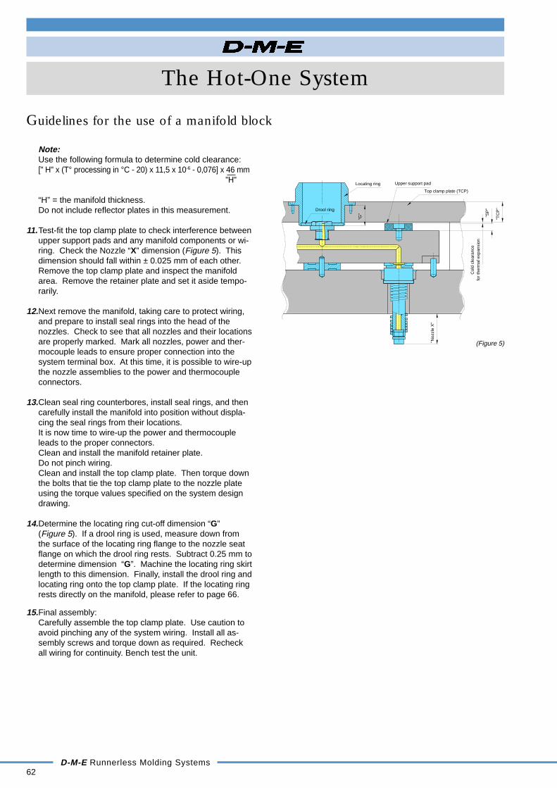
Note:Use the following formula to determine cold clearance:[" H" x (T° processing in °C - 20) x 11,5 x 10-6 - 0,076] x 46 mm
"H"
“H” = the manifold thickness.Do not include reflector plates in this measurement.
11.Test-fit the top clamp plate to check interference betweenupper support pads and any manifold components or wi-ring. Check the Nozzle “X” dimension (Figure 5). Thisdimension should fall within ± 0.025 mm of each other.Remove the top clamp plate and inspect the manifoldarea. Remove the retainer plate and set it aside tempo-rarily.
12.Next remove the manifold, taking care to protect wiring,and prepare to install seal rings into the head of thenozzles. Check to see that all nozzles and their locationsare properly marked. Mark all nozzles, power and ther-mocouple leads to ensure proper connection into thesystem terminal box. At this time, it is possible to wire-upthe nozzle assemblies to the power and thermocoupleconnectors.
13.Clean seal ring counterbores, install seal rings, and thencarefully install the manifold into position without displa-cing the seal rings from their locations.It is now time to wire-up the power and thermocoupleleads to the proper connectors.Clean and install the manifold retainer plate.Do not pinch wiring.Clean and install the top clamp plate. Then torque downthe bolts that tie the top clamp plate to the nozzle plateusing the torque values specified on the system designdrawing.
14.Determine the locating ring cut-off dimension “G”(Figure 5). If a drool ring is used, measure down fromthe surface of the locating ring flange to the nozzle seatflange on which the drool ring rests. Subtract 0.25 mm todetermine dimension “G”. Machine the locating ring skirtlength to this dimension. Finally, install the drool ring andlocating ring onto the top clamp plate. If the locating ringrests directly on the manifold, please refer to page 66.
15.Final assembly:Carefully assemble the top clamp plate. Use caution toavoid pinching any of the system wiring. Install all as-sembly screws and torque down as required. Recheckall wiring for continuity. Bench test the unit.
62
The Hot-One System
D-M-E Runnerless Molding Systems
Guidelines for the use of a manifold block
Drool ring
Col
d cl
eara
nce
Locating ring Upper support pad
Top clamp plate (TCP)
for
ther
mal
exp
ansi
on
"Noz
zle
X"
"TC
P"
"SP
"
"G"
(Figure 5)

D-M-E Runnerless Molding Systems63
The Hot-One System
Guidelines for the use of a manifold block
3. Bench test the unit with the temperature controller set at150 °C. Ensure all heaters come up to the desired setpoint. If desired set point is not reached, trouble shootthe system.
4. When the mold is installed in the press and all waterconnections are made, plug the power and thermocouplecables into the mold terminal box.
Note:Confirm the mainframe is off before making connectionsto the mold.
5. Set the temperature controller to the correct processingtemperature for the material being molded.
Note:Allow all heaters to go through a moisture dryoutprocess.
6. Bring the system up to the correct processing temperatu-re. Turn on mold water (cooling) and close the mold.Extremely cold water is not necessary. Water temperatu-re of 40 °C should keep the “A” side of the mold from ex-panding at a different rate than the “B” side of the mold.
7. When the runnerless molding system has reached setpoint and is normalized, the temperature controllers willshow a green light in the center of the deviation lightdisplay.
8. Make sure that the machine nozzle orifice is as large as,but not larger than, the nozzle seat orifice on the mani-fold.This will allow maximum throughput to the runnerlessmolding system and the mold cavities.
9. Be certain that the nozzle radius on the machine barrelmatches the nozzle seat radius on the manifold toprevent drooling. This should ensure a leak-proof seal.
10.Purge the barrel to ensure stable material enters the ma-nifold.
11.Move the machine nozzle into position against the mani-fold nozzle seat.
Manifold Filling Procedures :1. Ensure that the machine’s nozzle tip is properly seated
on the manifold nozzle seat.
2. Set machine back pressure to 20 to 35 bars.
3. Run the extruder until material flows through all nozzleorifices (gates). Run for an additional 5-15 sec. Thenclear gates and all mold surfaces of material. If themachine nozzle will not stay against tool, see Notesfollowing these instructions.
4. Move the sled back and decrease back pressure tonormal setting.
5. Set decompression/suck back at a minimum of 12 mm tocontrol drool.
6. Set molding parameters.
7. Move sled forward.
8. Start the molding process.
9. Check the system for leaks.
Wiring Guidelines
1. Ground connection :A ground connection must exist between the runnerlessmolding system (mold base) and the temperature controlsystem. This is accomplished via the mold power cable,which contains a ground wire (green or green/yellow)provided on the connector.To prevent electrical shock and ensure personal safety,the grounding wire should be connected to the moldbase or the terminal box itself.
2. Power and thermocouple connector placement :Do not place the mold’s power or thermocouple plugs inany area where they will be exposed to extreme tempe-rature or humidity.
3. Confirm zone numbering with respect to cavity numbers.
4. Wire channels :Use wire channels to ensure that wiring for nozzle andmanifold (including thermocouples) is routed away fromthe manifold. Use retainer clips to hold the wiring in thechannels to prevent wires from being cut or pinched du-ring final assembly.
5. Recheck resistances of heaters and T/Cs. Compare toprevious results. If values are different, trouble-shoot thesystem. Compare these values to those provided onyour design.
6. Adding additional wire to nozzle heater lead:If additional lead length is required, use the same type ofwire and use crimp contacts.
7. Adding additional wire to thermocouple leads:If additional lead length is required, use only type “J”thermocouple wire (positive (+) white, negative (-) red).
Note:In the event that multiple zones are ganged together tominimize the required number of control zones, it will benecessary to use one pair of thermocouple wires perganged set of nozzles. Run other thermocouple leadsinto the therminal box, insulating and identifying each foruse as spares if required at a later date.
Perform the following checks before instal-ling the runnerless molding system into thepress :
1. With the system properly grounded, execute an electricalcheck of each control zone for both power and thermo-couple connections. Check the heater leads for continui-ty. The resistance checked to ground of all heater leadsmust be greater than 200.000 Ω (200 K Ω).
2. Check each thermocouple circuit for continuity. It is alsoimportant to check for continuity between thermocouplesand heater elements. There should be no circuit be-tween the heater element and the thermocouple.

64D-M-E Runnerless Molding Systems
The Hot-One System
Guidelines for the use of a manifold block
Notes & General Comments :- If the system will not start up, throttle down or shut off wa-ter to the “A” plate. Water to the nozzle plate should remainon.
- If the machine will not extrude with the tool open, close thetool, jog the screw forward, open the tool, close the tool, andjog the screw forward again.
- If the machine nozzle will not stay against nozzle, proceedwith caution. Set injection forward pressure to 10 bars. Setinjection speed to slow, making sure the system is up totemperature. Move the sled into the tool and cautiously joginjection forward until material flows through gates. If ne-cessary, raise the injection pressure in steps up to, but notexceeding 35 bars. Clear gates and all mold surfaces ofmaterial. Finally, start the molding process.
- Never inject plastic through the hot runner system with themold open.
Important:Please treat these suggestions as guidelines only.Always follow standard moldmaking industry practices toensure the proper function of the mold and runnerlesssystem.
CAUTIONS !
Make sure you wear proper safety equipment such as glo-ves and face shield at all times.
Never use a torch to open frozen-off gates. This may dama-ge tips, gate detail, or the mold itself.
If you insert anything into the gate or tip to clear it, you mustfirst back the machine nozzle away from the tool.Check for drool out the back of the manifold before youstart. Drool here will indicate little or no pressure in the ma-nifold.
Never inject any runnerless molding system with high injec-tion pressure when the mold is open.
During the first 15 min. of operation, check system for leaks.Loss of shot size could be an indication of leakage.
Check to see that all cooling fans are operating in tempera-ture control main frames.
Input voltage to the main frame system must not be lessthan 208 vac.Voltages less than 240 VAC will require an extended time tobring the system up to its proper operating temperature.Lower voltages decrease effective wattage. For example:at 208 VAC, the effective wattage is 25 % less than that at240 VAC.
PIC-24 G
ZONE CONTACT
ZONE 1 A1-A2
ZONE 2 A3-A4
ZONE 3 B1-B2
ZONE 4 B3-B4
ZONE 5 A5-B5
ZONE 6 C1-C2
ZONE 7 C3-C4
ZONE 8 D1-D2
ZONE 9 D3-D4
ZONE 10 C5-D5
ZONE 11 E1-E2
ZONE 12 E3-E4
3 15
5
5B
A
C5
3 1
2
3
2
4
4
B1
A
2
3
4 C1
E5
D
E24
3
24
1
DZONE 10
ZONE 5
ZONE 2
ZONE 7
ZONE 3
ZONE 1
ZONE 4
ZONE 6
ZONE 12 ZONE 11
ZONE 8
ZONE 9
New mold power connector PIC-24 G
All new D-M-E Hotrunner systems will be fitted with thenew PIC-24 G connector.The PIC-24 G replaces the PIC-25 G connector and pro-vides for the higher continuous power requirements ofhotrunner systems and is conform with the new CE re-gulations. This modular connector, like its predecessor,connects 12 heating zones to the temperature controllerunit.The contacts are rated 20 Amps at 400 Volts and theconnector's footprint is only slightly larger than before.The main frames, MFPX-5, 8 or -12 G, are equipped withthe new power cable MPC-24 G that fits the new PIC-24 Gmold power connector.However, to overcome the transition problems from old tonew style, D-M-E offers the possibility to use adaptercables (length 0.5m).
MPC-2524 : connects molds with the old PIC-25 G to thenew MPC-24 G power cable.
MPC-2425 : connects molds with the new PIC-24 G tothe old MPC-25 G power cable.
Furthermore, the D-M-E terminal mounting boxes PTCXand PICX are provided with an extra plate so that bothstyles power connectors can be fitted.
Mold power input connector
Connection diagram

* For a correct regulation of thedistributor channels, install thethermocouple as close aspossible to the distributor channeland symmetrical to the heaters.
** Torque socket head cap screws M12 DIN 912 in 12.9 steadily with 25 NM.(*) Indicative value only – varies with plastic material and shot weights(Consult D-M-E if in doubt)(**) With tubular heater
The Hot-One System
D-M-E Runnerless Molding Systems65
Manifold layout - steel D-M-E 3 (1.2312) or steel D-M-E 5 (1.2344)
The Hot-One Manifold
EHA nozzles CIA nozzles Gate Mate 4TM Mini Gate Mate Osco®Valve Gate nozzles Micro Nozzles Multiple Gate nozzlesREF Series Series Series Series Series
GMB GMBSeries Series Series MSP MEP Series 38 Series 60
250 375 625 250 375 50 100 200 MSO MEO MGS MGS*A min 35 41 64 35 41 35 35 39 65 84 22 20 100 120*B min 39 51 77 39 51 39 39 47 100 116 23 18 85 105C min 36 52 66 36 52 52 52 36 52 66 30 30 36 36
(*) G min 46 56 66 56 56 46 46 56 56 66 46 46 70 88(**) ØL 6,3 9,5 16 6,5 9,5 9,5 9,5 6,3 9,5 16 3,5 3,5 8 8D
imen
sion
s
∆ LD = α x LD1 x ∆T∆ LD = Expanded nozzle distanceLD1 = Nozzle distance
(from ref. point) in mm∆T = Processing temperature in °C -
mold temperatureα = For instance
D-M-E steel n° 3 (1.2312) = 0.0000138
Manifold Watt densityMelt temperature Optimal power
T (°C) density (W/Cm3)T≤250 2,0T≥250 2,5
The Hot-One Manifold - Height recommendationsSeries 250, 375, GMB, Micro Series 250, 375, GMB, Micro Series 375, 625 With tubular heaters
When more 'Watt density'is required
Manifold with heater retainer plates Simple manifold Manifold with heater Solid Manifold Manifold with heaterand single level rectangular heater with single level retainer plates and with dual retainer plates and
heater single level heater level heaters dual level heaters
Ø A
B
M
min
58
Min
46
23
Min
66
33
38
19
Min
46
23
BHA M 20 BHA M 24A B B
6,3 36 409,5 46 5016 46 50
H7
H7
+0 +0,
015
M5 for riser pads**
for flat washer type thermocouple.
Thermocouple location to be on top of manifold when clearance between manifold and nozzle plate is 6,35 mm ( distance of 6,35 mm to be avoided. )
See chart for required torque2 end plug set screws required per end plug.
GZx16 or dowel pin
Dowel pin hole forcentre support pad
Ref. point
Bay
onet
ada
pter
for
ther
moc
oupl
e1/
8-27
NP
T
Cen
tral
14,2
714
,27
In line pattern
12 min
C minB minA min
G m
in
8
3/8-
24 N
FØ
12,
5
Ø L
M6 x 8
Ø 8
Ø L
min
.
Ø L
Din 74 Km 12
M6 x 8
( 2 per drop )
Set screw torque chartThread Nm
M 22 x 1,5 80M 32 x 1,5 210
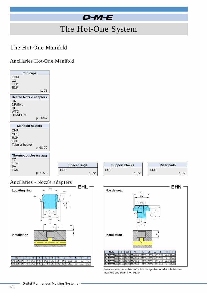
66D-M-E Runnerless Molding Systems
The Hot-One System
Ancillaries Hot-One Manifold
The Hot-One Manifold
EHL
REF. H H1 T A B D X Y E G CEHL 0252EX 73 34,9 5,53 84,1 100 75 50,8 63,5 65 10 3,2EHL 0253EX 73 34,9 5,53 117,5 140 100 82,6 95,2 98 10 3,2
Locating ring
Installation
EHN
REF. D SW G L L1 L2 d R HEHN 0001EX 38,10 32,00 M20x1,5 28,60 15,80 22,10 7,90 15,5 15,00EHN 0002EX 38,10 32,00 M20x1,5 28,60 15,80 22,10 7,90 0 15,00EHN 0003EX 47,60 38,00 M24x1,5 44,50 19,00 34,80 9,50 15,5 18,50EHN 0004EX 47,60 38,00 M24x1,5 44,50 19,00 34,80 9,50 0 18,50
Nozzle seat
Installation
End capsEHMGZEEPEDR
p. 73
Heated Nozzle adaptersHRDR/EHLDIWTOBHA/EHN
p. 66/67
Thermocouples (no view)
TCETCBATCM
p. 71/72
Support blocksECB
p. 72
Spacer ringsESR
p. 72
Manifold heatersCHRCHSECHEHPTubular heater
p. 68-70
R
H
Ø D
SW
L
L2
L1
3°
Ø d
G
MB
M8
H
H1
T
Ø B
Ø A
Ø Y
Ø X
Ø D
C
EG
Ancillaries - Nozzle adapters
Riser padsERP
p. 72
Provides a replaceable and interchangeable interface betweenmanifold and machine nozzle.

Installation Instructions
The Hot-One System
D-M-E Runnerless Molding Systems67
Ancillaries - Heated nozzle adapters
The Hot-One Manifold
BHA
REF. A B C D E F SW Gf7
BHA M20 Ø 8 Ø18 M20 x 1,5 15,8 60 30 16 20BHA M24 Ø12 Ø22 M24 x 1,5 19,0 68 40 24 30
Heated adapter
HR
REF. A BHR 30 30 20HR 40 40 30
Nozzle locator
REF. A D D1 D2DR 40 30 90 81 83DR 90 60 90 81 83
Distance bushing
DI
REF. A B C D E FWatt230 V
DI 30 x 30 30 45 30 35 50 70 330DI 40 x 30 40 55 30 40 55 75 380DI 40 x 40 40 55 40 40 55 75 490
Band heater with thermocouple type 'J'
Black wire 230 VBlack wire 230 VWhite wire + TCRed wire - type "J"
Note: to be heatedbefore assembly
HR
DR
WTO
DI
BHA
DR
REF. A BWTO 30 30 20WTO 40 40 30
Insulating ringWTO
+0,5-0
SW
3
5 E
D
Ø C
Ø A
Ø B
Ø F
Ø G
Ø 8
,5
5
245°
155
8.5
Ø 9
0
Ø 8
3
Ø A
Ø 1
3,5
Ø B
Ø 7
1 (4
)
Ø B
Ø9
Ø10
12
22
22
Ø AC
F
E
D
Ø B
5
Ø A
A
8
Ø D
2
Ø D
1
Ø D
REF. M A+0,02 øB+0,2 øC+0,2 L+1min.
BHA M20 M20 x 1,5 14,8 24 ø50 75BHA M24 M24 x 1,5 18 27 ø60 80
±1
+0,
1+
0,5
-0
H7
45°
32
16 m
in
Ø 71
M8 x 4
Ø 90
C
B
MMin
52,
5
A
25
10
L
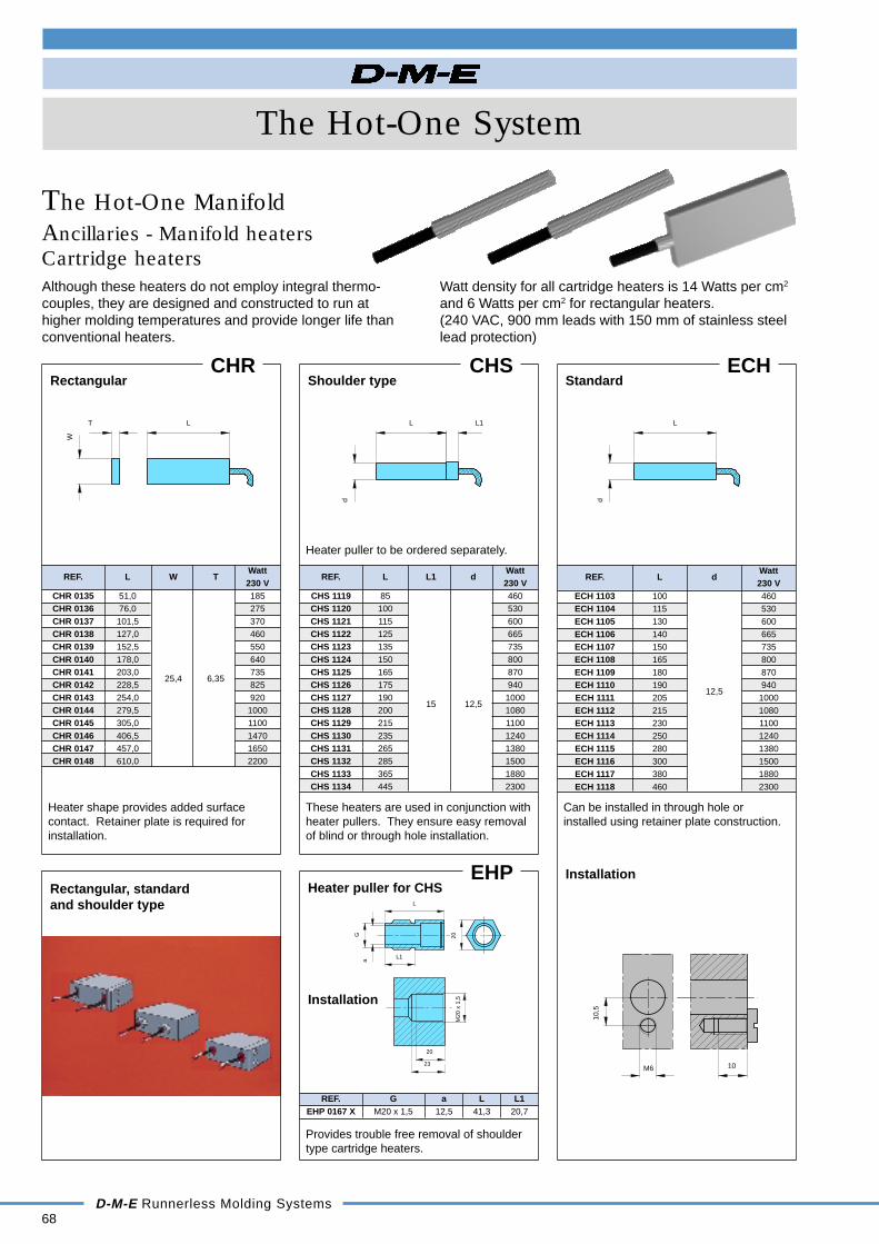
68D-M-E Runnerless Molding Systems
REF. G a L L1EHP 0167 X M20 x 1,5 12,5 41,3 20,7
The Hot-One System
Ancillaries - Manifold heatersCartridge heaters
The Hot-One Manifold
Watt density for all cartridge heaters is 14 Watts per cm2
and 6 Watts per cm2 for rectangular heaters.(240 VAC, 900 mm leads with 150 mm of stainless steellead protection)
RectangularCHR
REF. L W TWatt230 V
CHR 0135 51,0 185CHR 0136 76,0 275CHR 0137 101,5 370CHR 0138 127,0 460CHR 0139 152,5 550CHR 0140 178,0 640CHR 0141 203,0 735CHR 0142 228,5
25,4 6,35825
CHR 0143 254,0 920CHR 0144 279,5 1000CHR 0145 305,0 1100CHR 0146 406,5 1470CHR 0147 457,0 1650CHR 0148 610,0 2200
Heater shape provides added surfacecontact. Retainer plate is required forinstallation.
CHS
REF. L L1 dWatt230 V
CHS 1119 85 460CHS 1120 100 530CHS 1121 115 600CHS 1122 125 665CHS 1123 135 735CHS 1124 150 800CHS 1125 165 870CHS 1126 175 940CHS 1127 190 1000CHS 1128 200
15 12,51080
CHS 1129 215 1100CHS 1130 235 1240CHS 1131 265 1380CHS 1132 285 1500CHS 1133 365 1880CHS 1134 445 2300
These heaters are used in conjunction withheater pullers. They ensure easy removalof blind or through hole installation.
Heater puller to be ordered separately.
EHP
Provides trouble free removal of shouldertype cartridge heaters.
Shoulder type
Heater puller for CHS
Installation
Although these heaters do not employ integral thermo-couples, they are designed and constructed to run athigher molding temperatures and provide longer life thanconventional heaters.
ECH
REF. L dWatt230 V
ECH 1103 100 460ECH 1104 115 530ECH 1105 130 600ECH 1106 140 665ECH 1107 150 735ECH 1108 165 800ECH 1109 180 870ECH 1110 190
12,5940
ECH 1111 205 1000ECH 1112 215 1080ECH 1113 230 1100ECH 1114 250 1240ECH 1115 280 1380ECH 1116 300 1500ECH 1117 380 1880ECH 1118 460 2300
Can be installed in through hole orinstalled using retainer plate construction.
Standard
InstallationRectangular, standardand shoulder type L
L1
Ga
20M
20 x
1,5
23
20
10,5
10M6
L
W
T
d
L
d
L1L
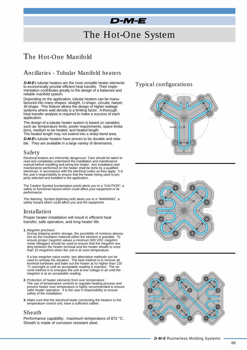
The Hot-One System
D-M-E Runnerless Molding Systems69
Typical configurations
Ancillaries - Tubular Manifold heaters
The Hot-One Manifold
D-M-EETC 0168 X
D-M
-EE
TC
016
8 X
D-M
-EE
TC
016
8 X
D-M-E ETC 0168 X
D-M-E's tubular heaters are the most versatile heater elementsto economically provide efficient heat transfer. Their imple-mentation contributes greatly to the design of a balanced andreliable manifold system.Depending on the application, tubular heaters can be manu-factured into many shapes: straight, U-shape, circular, hairpin,W-shape. This feature allows the design of higher wattagesystems where watt density is a limiting factor. A thoroughheat transfer analysis is required to make a success of eachapplication.The design of a tubular heater system is based on variablessuch as: temperature limits, power requirements, space limita-tions, medium to be heated, and heated length.The heated length may not extend into a sharp bend area.D-M-E's tubular heaters have proven to be durable and relia-ble. They are available in a large variety of dimensions.
SafetyElectrical heaters are inherently dangerous! Care should be taken toread and completely understand the installation and maintenancemanual before installing and wiring the heater. Any installation andmaintenance performed on the heater shall be done by a qualifiedelectrician, in accordance with the electrical codes as they apply. It isthe user’s responsibility to ensure that the heater being used is pro-perly selected and installed in the application.
The Caution Symbol (exclamation point) alerts you to a “CAUTION”, asafety or functional hazard which could affect your equipment or itsperformance.
The Warning Symbol (lightning bolt) alerts you to a “WARNING”, asafety hazard which could affect you and the equipment.
InstallationProper heater installation will result in efficient heattransfer, safe operation, and long heater life.
1. Megohm precheck :During shipping and/or storage, the possibility of moisture absorp-tion by the insulation material within the element is possible. Toensure proper megohm values a minimum 500 VDC megohmmeter (Megger) should be used to ensure that the megohm rea-ding between the heater terminal and the heater sheath is morethan 10 megohms when the unit is at room temperature.
If a low megohm value exists, two alternative methods can beused to remedy the situation. The best method is to remove allterminal hardware and bake out the heater at no higher than 120°C overnight or until an acceptable reading is reached. The se-cond method is to energize the unit at low voltage in air until themegohm is at an acceptable reading.
2. Protection of heater elements from over temperature :The use of temperature controls to regulate heating process andprevent heater over temperature is highly recommended to ensuresafer heater operation. It is the user’s responsibility to ensuresafety of the installation.
3. Make sure that the electrical leads connecting the heaters to thetemperature control unit, have a sufficient caliber.
SheathPerformance capability: maximum temperature of 872 °C.Sheath is made of corrosion resistant steel.

Never allow heated section to extend past edge of manifold
- All shapes and dimensions possible- Balanced manifolds- Long life heaters- Consult D-M-E
70D-M-E Runnerless Molding Systems
The Hot-One System
Ancillaries - Manifold heaters
Tubular heaters
The Hot-One Manifold
Lmm < 500< 1000 < 2000 < 2800 < 3600 < 4300> 500 > 1000 > 2000 > 2800 > 3600
C 25 32 38 42 44 51
Use the following formula to determine cold clearance:["H" x (T° processing in °C - 20) x 11,5 x 10-6 - 0,076] X 46 mm
"H"
"H" = the manifold thickness.Do not include heater covers in this measurement.
Dowel pinRiser pad
Nozzle seat
Manifold retainer plate
Dowel pin
Nozzle plate
"E"
"D""H"1,51,5
*MC
cold endmin distance before end
reflector plate
ceramic insulator sheath coil cold pin
refer to chart below
cold end heated length cold end
*M = C + 13 + 0,005 x L
C C
25L
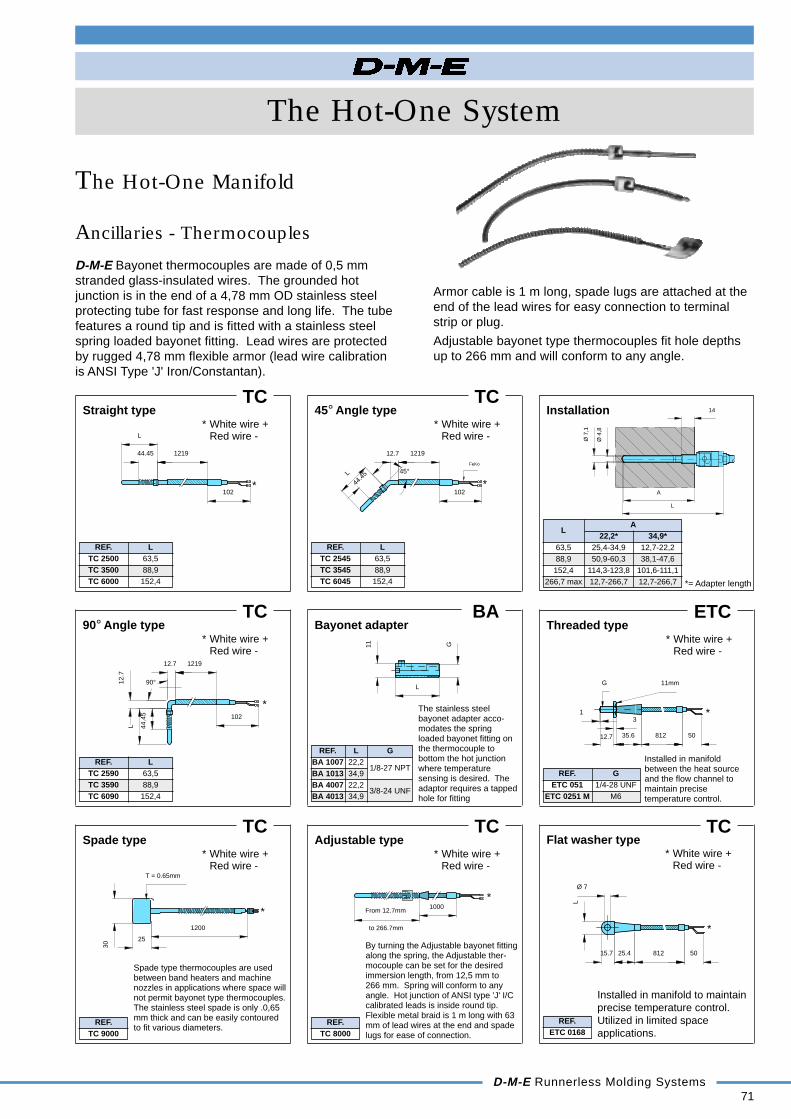
The Hot-One System
D-M-E Runnerless Molding Systems71
Ancillaries - Thermocouples
The Hot-One Manifold
D-M-E Bayonet thermocouples are made of 0,5 mmstranded glass-insulated wires. The grounded hotjunction is in the end of a 4,78 mm OD stainless steelprotecting tube for fast response and long life. The tubefeatures a round tip and is fitted with a stainless steelspring loaded bayonet fitting. Lead wires are protectedby rugged 4,78 mm flexible armor (lead wire calibrationis ANSI Type 'J' Iron/Constantan).
Armor cable is 1 m long, spade lugs are attached at theend of the lead wires for easy connection to terminalstrip or plug.
Adjustable bayonet type thermocouples fit hole depthsup to 266 mm and will conform to any angle.
Straight typeTC
REF. LTC 2500 63,5TC 3500 88,9TC 6000 152,4
* White wire +Red wire -
90° Angle typeTC
REF. LTC 2590 63,5TC 3590 88,9TC 6090 152,4
* White wire +Red wire -
Spade typeTC
REF.TC 9000
* White wire +Red wire -
Spade type thermocouples are usedbetween band heaters and machinenozzles in applications where space willnot permit bayonet type thermocouples.The stainless steel spade is only .0,65mm thick and can be easily contouredto fit various diameters.
45° Angle typeTC
REF. LTC 2545 63,5TC 3545 88,9TC 6045 152,4
* White wire +Red wire -
Bayonet adapterBA
REF. L GBA 1007 22,2BA 1013 34,9
1/8-27 NPT
BA 4007 22,2BA 4013 34,9
3/8-24 UNF
Adjustable typeTC
REF.TC 8000
* White wire +Red wire -
The stainless steelbayonet adapter acco-modates the springloaded bayonet fitting onthe thermocouple tobottom the hot junctionwhere temperaturesensing is desired. Theadaptor requires a tappedhole for fitting
By turning the Adjustable bayonet fittingalong the spring, the Adjustable ther-mocouple can be set for the desiredimmersion length, from 12,5 mm to266 mm. Spring will conform to anyangle. Hot junction of ANSI type 'J' I/Ccalibrated leads is inside round tip.Flexible metal braid is 1 m long with 63mm of lead wires at the end and spadelugs for ease of connection.
Installation
LA
22,2* 34,9*63,5 25,4-34,9 12,7-22,288,9 50,9-60,3 38,1-47,6
152,4 114,3-123,8 101,6-111,1266,7 max 12,7-266,7 12,7-266,7 *= Adapter length
Ø 7
,1
Ø 4
,8
L
A
14
to 266.7mm
*1000
From 12.7mm
T = 0.65mm
*1200
25
30
*
90°12.7
121912.7
102
44.4
5
L
11
L
G
FeKo
*45°
12.7
L
44.4
5
1219
102*
1219
102
44.45
L
Threaded typeETC
REF. GETC 051 1/4-28 UNF
ETC 0251 M M6
* White wire +Red wire -
Installed in manifoldbetween the heat sourceand the flow channel tomaintain precisetemperature control.
G 11mm
*1
12.7 35.6
3
50812
REF.ETC 0168
TCFlat washer type
* White wire +Red wire -
Installed in manifold to maintainprecise temperature control.Utilized in limited spaceapplications.
*
Ø 7
5081225.415.7
L

72D-M-E Runnerless Molding Systems
The Hot-One System
Ancillaries - Thermocouples
The Hot-One Manifold
Nozzle typeTC
Cylindrical type
Installation
TCM
REF.TCM 0003
Ancillaries - OthersERP
REF. L X T d d1 S EERP 0161 50,0 10,0 15,0 10,0 5,7 4,5 28,6ERP 0162 50,0 20,0 15,0 10,0 5,7 4,5 28,6ERP 0163 101,6 9,5 25,4 10,0 5,7 4,0 28,6ERP 0164 101,6 19,00 25,4 10,0 5,7 4,0 28,6
Riser pad
Supports manifold opposite nozzles. Reduces heat loss andmaintains spacing between manifold and clamping plate.
ESR
REF. d1 d X Mat.ESR 0157 10,3 22 6,35ESR 0163 10,3 22 10ESR 0164 10,3 22 20
Steel
ESR 0166 13,5 22 20ESR 0463 10,3 22 10ESR 0464 10,3 22 20 TitaniumESR 0466 13,5 22 20
Spacer ring
Maintains spacing between manifold and support plate, andtitanium greatly reduces heat loss.
ECBSupport block A B C
Support manifold center spacing, while minimizing heat transferfrom manifold. The titanium greatly reduces heat loss.
REF. d d1 X Type Mat.ECB 0161 63,50 6,35 6,35ECB 0166 30,00 8,00 20,00 SteelECB 0167 40,00 8,00 10,00 CECB 0466 30,00 8,20 20,00ECB 0467 30,00 8,20 10,00ECB 0501 20,00 5,20 10,00 A
Titanium
ECB 0502 40,00 8,20 10,00 B
ECB
REF. d d1 X Mat.ECB 0500 16,00 4,20 6,00 Titanium
Support block
The titanium support block greatly reduces heat loss.
REF. L I dTC 19 70 1000 1,6
Installed in Hot-One nozzles
* White wire +Red wire -
Installed in Multiple gatenozzles when used withmanifold.
90° Screw-in type
Installation
ETC
REF.ETC 0170
Installed in Micro Hot-Onemanifold to maintain precisetemperature control.
Ø 3
,1
9
10
Ø 3
* White wire +Red wire -
±0.
16,8
11,5
8
M3
Ø 4
820
6
12
Ø 4
+0.
3-0
.0
L
X
S
Ø d
Ø d1
T
E
ECB-0501 ECB-0502 ECB-0466/0467ECB-0161/0166/0167
Ø d1
Ø d
XXX
Ø d
Ø d1
Ø d
Ø d1
*L
Ød
I
X
Ø d
Ø d1
Titanium steel
X
Ø d
Ø d1Ø d1
Ø d
X

REF. M L2 SWEHM 3215 32x1,5 15 17EHM 2215 22x1,5 12,5 10EHM 1620 16x2,0 9 8EHM 1420 14x2,0 16 6EHM 1217 12x1,75 16 6
The Hot-One System
D-M-E Runnerless Molding Systems73
Ancillaries - End plugs
The Hot-One Manifold
EEP
REF. A C d1 L L1 D d M L2 SWEEP 2440 30 2,0 24 60 40 30 24 32 x 1,5 15 17EEP 1630 20 1,5 16 45 30 20 16 22 x 1,5 12,5 10EEP 1018 14 1,0 10 28 18 14 10 16 x 2,0 9 8EEP 0815 12 1,0 8 25 15 12 8 14 x 2,0 16 6EEP 0612 10 1,0 6 19,5 12 10 6 12 x 1,75 16 6
Cylindrical end plug
REF. EEP 2440 EEP 1630 EEP 1018 EEP 0815 EEP 0612Ø PH7 24 16 10 8 6
Ø Q (+0,2) 30 20 14 12 10R 38 28,5 17 14 11S 12 10 6 6 6
C min. L + 30 L + 25 L + 18 L + 16 L + 16M 32 x 1,5 22 x 1,5 16 x 2,0 14 x 2,0 12 x 1,75
L max. 60 45 28 25 19,5Rv min. 14 10 7 6 5
Installation
+0,1
Spare Parts
Cylindricalthreaded plug
EHM
REF. A d1 CEDR 2420 30 24 2,0EDR 1615 20 16 1,5EDR 1010 14 10 1,0EDR 0810 12 8 1,0EDR 0610 10 6 1,0
Seal ring
REF.GZ 6 x 16
Set screwallan head
EDR GZ
EEP
REF. d D L1 L F G M L2 SWEEP 2001 6 9,0 6 15 6 6 M12x1,75 16 6EEP 2002 9 13,5 8 20 10 9 M16x2 20 8EEP 2003 12 16,0 10 22 14 12 M20x2,5 20 10
Conical end plug
Installation
REF. OL min.EEP 2001 31EEP 2002 40EEP 2003 42
EHM
REF. M L2 SW ForEHM 1217 M12 x 1,75 16 6 EEP 2001EHM 1621 M16 x 2 20 8 EEP 2002EHM 2025 M20 x 2,5 20 10 EEP 2003
Set screw
Spare Parts
h5
-0,2
-0,3
+0,3+0,1
±0,3C
Ø A
EDR EEP GZ EHM
SW
16 3
M6
Ø d
1
L2
M
Ø DØ
d
L
L1
+0.15-0.00
+0
.01
-0.0
0
-0.0
+0
.2
EEP EHM
SW
L2
M
12°30'
L
Ø D
Ø F
Ø d
G
L1
to be weldedagainst rotation
OL min
SRv
Ø Q
M
C min.
L max.
Ø P
R
SW
M
L2
M6
316
Ø A
C
Ø d
1
SW
M
L2
EHM GZ EEP EDR EHM EEP
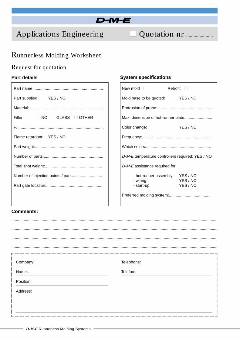
68D-M-E Runnerless Molding Systems
Applications Engineering Quotation nr ......................
Part details
Part name:..............................................................
Part supplied: YES / NO
Material:...................................................................
Filler: NO GLASS OTHER
%.............................................................................
Flame retardant: YES / NO
Part weight:.............................................................
Number of parts:.....................................................
Total shot weight:...................................................
Number of injection points / part:...........................
Part gate location:..................................................
Comments:
........................................................................................................................................................................................
.........................................................................................................................................................................................
Company:
Name:.
Position:
Address:
Telephone:
Telefax:
Request for quotation
Runnerless Molding Worksheet
System specifications
New mold Retrofit
Mold base to be quoted: YES / NO
Protrusion of probe:.................................................
Max. dimension of hot-runner plate:.........................
Color change: YES / NO
Frequency:..............................................................
Which colors:..........................................................
D-M-E temperature controllers required: YES / NO
D-M-E assistance required for:
- hot-runner assembly: YES / NO- wiring: YES / NO- start-up: YES / NO
Preferred molding system:......................................

The Hot-One System
D-M-E Runnerless Molding Systems69
* This booklet cancels and replaces all preceding ones. All rights reserved for technical modifications.
IMPORTANT
"This Runnerless Molding System was designed in all fairness by D-M-E ApplicationsEngineering according to the state-of-the-art, and is the result of a long experiencecombined with up-to-date computer-assisted methods. Also the design was madeaccording to the then available information.
For Runnerless Molding Systems supplied complete by D-M-E, manifold andcomponents, a guarantee is implied that the molten plastic material will be deliveredat the cavity gate in good conditions of discharge flow, pressure and integrity,provided that the material is genuine and does not present an abnormal behavior.
Because other important process and product design parameters are not under thecontrol of the Runnerless Molding System designer, D-M-E will not be responsible forany problem that will affect the molded part. However, D-M-E will offer its bestsupport to solve those problems.
The liability of D-M-E, if any, is limited to the value of the delivered manifold andRunnerless Molding components."

D-M-E Belgium N.V. • Industriepark Noord I • B-2800 Mechelen (Belgium) • Tel. +int. 32.15 / 21 50 11 • Fax +int. 32.15 / 21 82 35
8 / 8024038 /1296 - E Printed in Belgium - MD61468
Runnerless Molding Systems
Hot Sprue Bushings• Separate leaflet
Runnerless Molding Systems• The Cool-One system• The Hot-One system
• Standard system• Micro system• Osco® Valve Gate system
Temperature Controllers• Separate leaflet
MOLDING SYSTEMS
TemperatureControllers
Hot SprueBushings
RunnerlessMoldingSystems
We Build Productivity