THE HISTORY OF DEEP MIXING IN NEW ORLEANS - History of DM in New... · 3 Figure 1. Soil properties...
22
1 THE HISTORY OF DEEP MIXING IN NEW ORLEANS Dr. Donald A. Bruce, C.Eng., FICE 1 Dr. Peter R. Cali, P.E. 2 Mark L. Woodward, P.E. 3 1 President, Geosystems, L.P., P.O. Box 237, Venetia, PA 15367, U.S.A., Phone: 724-942-0570, Fax: 724-942- 1911, [email protected] 2 President, Sea Level Engineering, LLC, 4912 Lake Vista Drive, Metairie, LA 70006, U.S.A., Phone: 504- 862-1001, [email protected] 3 Geotechnical Engineer, U.S. Army Corps of Engineers, P.O. Box 60267, New Orleans, LA 70160-0267, U.S.A, Phone: 504-862-1006, Fax: 504-862-1091, [email protected] ABSTRACT: Although the Deep Mixing Method (DMM) had been applied in the United States since 1986, it was not until the mighty efforts required to quickly and reliably rebuild the levee system in the aftermath of Hurricanes Katrina and Rita that it was used in the New Orleans area. Whereas the soils had long been judged to be amenable to DMM, other traditional methods of ground engineering had previously been used. With what in hindsight can be seen to have been a singularly astute decision, the U.S. Army Corps of Engineers, New Orleans District (USACE) commissioned a full-scale DMM field test in typical New Orleans conditions at the beginning of the decade. Though the test was very successful in all regards, the concept of using DMM in routine construction projects was shelved since it was perceived to not be cost effective. However, the technical and scheduling challenges of the Task Force Guardian projects in 2006 overcame this perception and, from that time onwards, there has been a virtually continuous succession of DMM projects, using both Wet and Dry Methods. This path has culminated in the huge project at Lake Ponchartrain, LPV111, the largest DMM application yet conducted outside Japan. INTRODUCTION It always seemed that the soils underlying New Orleans, LA, and all its flood protection levees and related structures, would be amenable to the benefits of the Deep Mixing Methods (DMM). In many ways, these soils mirrored, in their properties, those in the birth places of DMM, namely the Nordic Countries and Japan (FHWA, 2000). For example, they comprised similar sequences of soft cohesive sediments of very high moisture contents, and typically high organic contents, often concentrated into specific horizons, of variable lateral and vertical continuity, reflecting their depositional history. However, there must be a problem before there is a solution. Prior to the catastrophic events of late August, 2005, there was no incentive to introduce a new, exotic technology (i.e., DMM) into a region where foundation solutions were either provided by “traditional” methods (e.g., driven piles) or were simply not required (i.e., the levees were intact). By an act of great good fortune, the authors had met in the mid-1990’s at a geotechnical seminar in New Orleans: the subject of the interface was Deep Mixing, as practiced elsewhere in the U.S., Japan and the Nordic Countries. By the late 1990’s, the New Orleans District, U.S. Army Corps of Engineers, had raised sufficient research funding to conduct desk and bench studies of the potential for Deep Mixing in New Orleans conditions, and this
Transcript of THE HISTORY OF DEEP MIXING IN NEW ORLEANS - History of DM in New... · 3 Figure 1. Soil properties...

1
THE HISTORY OF DEEP MIXING IN NEW ORLEANS
Dr. Donald A. Bruce, C.Eng., FICE
1
Dr. Peter R. Cali, P.E.2
Mark L. Woodward, P.E.3
1 President, Geosystems, L.P., P.O. Box 237, Venetia, PA 15367, U.S.A., Phone: 724-942-0570, Fax: 724-942-
1911, [email protected] 2 President, Sea Level Engineering, LLC, 4912 Lake Vista Drive, Metairie, LA 70006, U.S.A., Phone: 504-
862-1001, [email protected] 3 Geotechnical Engineer, U.S. Army Corps of Engineers, P.O. Box 60267, New Orleans, LA 70160-0267,
U.S.A, Phone: 504-862-1006, Fax: 504-862-1091, [email protected]
ABSTRACT: Although the Deep Mixing Method (DMM) had been applied in the United
States since 1986, it was not until the mighty efforts required to quickly and reliably rebuild
the levee system in the aftermath of Hurricanes Katrina and Rita that it was used in the New
Orleans area. Whereas the soils had long been judged to be amenable to DMM, other
traditional methods of ground engineering had previously been used. With what in hindsight
can be seen to have been a singularly astute decision, the U.S. Army Corps of Engineers,
New Orleans District (USACE) commissioned a full-scale DMM field test in typical New
Orleans conditions at the beginning of the decade. Though the test was very successful in all
regards, the concept of using DMM in routine construction projects was shelved since it was
perceived to not be cost effective. However, the technical and scheduling challenges of the
Task Force Guardian projects in 2006 overcame this perception and, from that time onwards,
there has been a virtually continuous succession of DMM projects, using both Wet and Dry
Methods. This path has culminated in the huge project at Lake Ponchartrain, LPV111, the
largest DMM application yet conducted outside Japan.
INTRODUCTION
It always seemed that the soils underlying New Orleans, LA, and all its flood protection
levees and related structures, would be amenable to the benefits of the Deep Mixing Methods
(DMM). In many ways, these soils mirrored, in their properties, those in the birth places of
DMM, namely the Nordic Countries and Japan (FHWA, 2000). For example, they comprised
similar sequences of soft cohesive sediments of very high moisture contents, and typically
high organic contents, often concentrated into specific horizons, of variable lateral and
vertical continuity, reflecting their depositional history. However, there must be a problem
before there is a solution. Prior to the catastrophic events of late August, 2005, there was no
incentive to introduce a new, exotic technology (i.e., DMM) into a region where foundation
solutions were either provided by “traditional” methods (e.g., driven piles) or were simply not
required (i.e., the levees were intact).
By an act of great good fortune, the authors had met in the mid-1990’s at a geotechnical
seminar in New Orleans: the subject of the interface was Deep Mixing, as practiced
elsewhere in the U.S., Japan and the Nordic Countries. By the late 1990’s, the New Orleans
District, U.S. Army Corps of Engineers, had raised sufficient research funding to conduct
desk and bench studies of the potential for Deep Mixing in New Orleans conditions, and this

2
lead logically to the design and implementation of a full-scale test program in representative
conditions in 2003.
The results of this test were extremely valuable and informative, not least of all because of
the insight it generated regarding the challenges posed by the local soil conditions to
achieving efficient, homogeneous mixing. Nevertheless, the absence of a pressing need,
allied to the perception that DMM was somewhat too expensive and somehow too
sophisticated for local practices, led to the shelving of DMM as a viable and reliable
foundation stabilization technology.
By macabre coincidence, the definitive papers on the Test Program were presented at the
international DMM conference in Stockholm, Sweden in April of 2005 (Cali et al., 2005a and
b). In August of that same year, Hurricanes Katrina and Rita devastated the Mississippi Delta
region, causing unfathomable human, economic and emotional damage. USACE established
Task Force Guardian, whose mission was to restore the flood protection afforded by the levee
and flood wall systems to pre-Katrina levels by June 1, 2006. This involved about 169 miles
of repair work. As a direct consequence of the specific goals of the mission, DMM surfaced
as a viable construction technique, offering significant technical and scheduling advantages.
DMM techniques were therefore used in several emergency projects, and in many medium-
sized projects between then (2006) and 2009. This may be regarded as Phase 2 of Deep
Mixing in New Orleans.
Thereafter, there has been a third phase, epitomized by the huge LPV 111 project. The deep
mixing conducted in that project represents the largest DMM project ever conducted outside
of Japan.
PHASE 1:
THE FULL-SCALE FIELD TEST OF 2003 (Cali et al., 2005a; Cali et al., 2005b)
With a view to the possible construction of a flood control structure at the Inner Harbor
Navigation Channel (IHNC) in New Orleans, a DMM test program was funded by USACE.
To satisfy design requirements, the shear strength of the upper 7.8 m of native soil had to be
increased from the original 17 kPa to 96 kPa. Calculations showed that this could be
accomplished with columns of average shear strength 290 kPa at a replacement ratio of 30%.
A test section was a prerequisite since this type of construction had not been used by the
USACE before.
The goals of the test section were to :
optimize design (and cost estimating) procedures;
demonstrate the ability of DMM to satisfy the design intent;
obtain better understanding of column-soil interaction in a slope stability application; and
establish QA/QC procedures.
The area comprised fill and recent Holocene soils consisting of swamp/marsh deposits,
deltaic plain deposits, beach ridge sand deposits, and near shore Gulf deposits to depths
equivalent to Elevation -19.5 m. Test details are provided in Figure 1 and are summarized in
Figure 2. These conditions are not atypical of the New Orleans area.

3
Figure 1. Soil properties obtained from one 127 mm diameter,
undisturbed boring (Imperial Units).
Figure 2. Generalized site stratigraphy and soil properties (Imperial Units).

4
The test program was planned for three phases: a bench scale test and a full-scale test section
in two phases, the specific objectives of which were:
1) Bench Scale Test and Phase 1 Test – To obtain comparative data regarding the in-situ
relationship between column shear strength and column design parameters, such as
design mix, loading rate and mixing energy.
2) Bench Scale Test and Phase 1 Test – From full-scale column data, adjust the initial
design for the Phase II test section so that loading to failure could be achieved.
3) Phase II Load Test – To verify column/soil interaction assumptions made for infinite
levee slope stability analyses upon which the actual flood protection levee design would
be based.
4) Phase I and II Tests – To study the construction methods, quality test methods, and
intangible aspects of construction using lime cement columns.
To accomplish the stated goals, a full-scale test section was loaded to failure in Phase II.
The bench scale test (a dry DMM method was anticipated) featured four different soil types
and five different mixtures and dosages of binders, and led to the use of mainly cement, but
also lime-cement-columns in the 10.5 m long, 0.8 m diameter test columns themselves (Table
1). In addition to the suite of tests shown in this table, the upper 5 m of four of these columns
were excavated (Photograph 1), sealed, inspected, tested in mass, and further cored, to
determine the properties obtained, e.g., Figure 3. Many Phase I lessons were learned, not all
positive or encouraging given the “learning curve” difficulties of the mixing process, and the
variability of the native materials.
Two “test cells,” with 12% and 20% replacement ratios, respectively, were built (Figure 4)
with the overlapping columns arranged in panels. These replacement ratios were selected to
represent typical minimum and standard ratios employed at the time. The depth of columns
reflected the capacity of the equipment available for the test. All columns were installed with
100% cement binder. Each cell was instrumented to measure load distribution between the
soil and columns, pore pressure increase in the soil, and depth and inclination of the failure
surface, in real time. An untreated reference cell was also loaded to failure (using the same
steel ingots (Photograph 2).

5
Table 1. As-Built Phase I Columns and Testing
MIX
COMPOSITION
CEMENT
FACTOR
(kg/m3)
MIX
METHOD
TESTING
TYPE
1 100% C 150 1 RCPT
2 100% C 150 1 PM
3 100% C 150 1 EXP
4 100% C 150 1 RCPT
5 25% L / 75% C 150 1 PM
6 100% C 134 1 RCPT
7 100% C 200 1 RCPT
8 100% C 130 1 PM
9 100% C 200 1 EXP
10 100% C 139 1 PM
11 25% L / 75% C 200 1 PM
12 100% C 136 1 RCPT
13 100% C 200 1 RCPT
14 100% C 130 2 PM
15 100% C 150 1 EXP
16 100% C 144 1 PM
17 25% L / 75% C 150 2 PM
18 100% C 153 1 RCPT
19 100% C 200 1 RCPT
20 100% C 200 2 PM
21 100% C 200 1 EXP
22 100% C 154 1 PM
23 25% L / 75% C 200 2 PM
24 100% C 150 1 CPT RCPT = Reverse Column Penetration Test (FHWA 2001)
PM = Pressuremeter Test (FHWA 2001)
EXP = Exposed for 6′ Coring and UU Testing
Columns 2, 5, 8, 11, 14, 17, 20 and 23 were also bored using 3″ sampler
and UU testing
Mix Method 1 – Injection of binder during both penetration and
withdrawal
Mix Method 2 – Same as Mix Method 1 with a remix in Organic layer
Cement Factor – The weight of dry binder placed per cubic meter of soil

6
Photograph 1. Excavated test column.
Figure 3. Shear test results on core samples.

7
Figure 4. As-built cell configuration with 12% and 20% replacement ratios.
Photograph 2. Cell A fully loaded with 1 million kilograms of steel (177 kN/m2).
Invaluable information was obtained during this program. In short, while the applicability of
(dry) Deep Mixing had been clearly demonstrated, there remained doubts (and, arguably,
misunderstandings) in certain quarters about its technical capabilities and its comparative cost
effectiveness: it was decided to keep the technique “on ice.”
PHASE 2: SUMMARY OF PROJECTS (2006-2009)
The “ice,” in the form of Hurricanes Katrina and Rita, melted in late 2005 and 2006. As
noted above, the requirements placed on Task Force Guardian were such that time was far
more of the essence than cost, while technical uncertainties could be compensated by
conservatism in design. From early 2006 to mid-2009, there were numerous small- to
8
medium-sized DMM projects which had now attracted the wet methods (Ratio, Inc.) as well
as the dry methods (Hayward Baker, Inc.).
In the majority of projects, the beautiful path was followed in exemplary fashion: bench
scale testing, followed by a full-scale field, demonstration test, in turn followed by a closely
instrumented and monitored production phase, with later verification of in-situ DMM
properties, typically by coring.
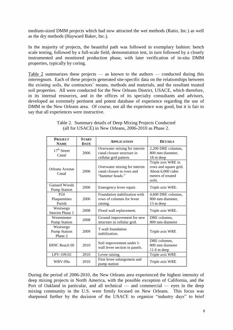
Table 2 summarizes these projects — as known to the authors — conducted during this
interregnum. Each of these projects generated site-specific data on the relationships between
the existing soils, the contractors’ means, methods and materials, and the resultant treated
soil properties. All were conducted for the New Orleans District, USACE, which therefore,
in its internal resources, and in the offices of its specialty consultants and advisors,
developed an extremely pertinent and potent database of experience regarding the use of
DMM in the New Orleans area. Of course, not all the experience was good, but it is fair to
say that all experiences were instructive.
Table 2. Summary details of Deep Mixing Projects Conducted
(all for USACE) in New Orleans, 2006-2010 as Phase 2.
PROJECT
NAME
START
DATE APPLICATION DETAILS
17th
Street
Canal 2006
Overwater mixing for interim
canal closure structure in
cellular grid pattern.
2,200 DRE columns,
800 mm diameter,
18 m deep
Orleans Avenue
Canal 2006
Overwater mixing for interim
canal closure in rows and
“hammer heads.”
Triple axis WRE in
rows and square grid.
About 6,000 cubic
meters of treated
soils.
Gainard Woods
Pump Station 2006 Emergency levee repair. Triple axis WRE.
P24
Plaquemines
Parish
2006
Foundation stabilization with
rows of columns for levee
raising.
4,600 DRE columns,
800 mm diameter,
13 m deep
Westwego
Interim Phase 1 2008 Flood wall replacement. Triple axis WRE.
Westminster
Pump Station 2008
Ground improvement for new
structure in cellular grid.
DRE columns,
800 mm diameter
Westwego
Pump Station
Phase 2
2009 T-wall foundation
stabilization. Triple axis WRE
IHNC Reach III 2010 Soil improvement under I-
wall levee section in panels.
DRE columns,
800 mm diameter
11.6 m deep
LPV-109.02 2010 Levee raising. Triple axis WRE
WBV-09a 2010 First levee enlargement and
pump station Triple axis WRE
During the period of 2006-2010, the New Orleans area experienced the highest intensity of
deep mixing projects in North America, with the possible exception of California, and the
Port of Oakland in particular, and all technical — and commercial — eyes in the deep
mixing community in the U.S. were firmly focused on New Orleans. This focus was
sharpened further by the decision of the USACE to organize “industry days” to brief

9
potential participants about the nature, scale and timing of the anticipated upcoming works.
These “works in planning” were of a scale and intensity not heretofore seen in North
America and — amongst other natural reactions — attracted growing international interest.
PHASE 2 – ILLUSTRATIVE DETAILS
Bench scale test data were freely available for 7 of the 10 New Orleans projects of Phase 2.
These are summarized in Table 3.
Regarding the “wet” method, their bench scale testing of the Westwego Pump Station soils is
typical. They anticipated the use of two cement factors, correlated to column depth (to
Elevation 24 m), and the two predominant soils “organic clay” over “clay.” The test data are
summarized in Table 4. For the upper 8 m of organic soils, the experimental data of Figure 5
were obtained. Predictably, the soils of the lower 8-24 m showed significantly higher
strengths at all cement factors (Figure 6), while the authors could find no logical explanation
for some samples having lower 14-day strengths than at 7 days.
For the “dry” method, the program conducted for the Plaquemines Parish (P24) project is
typical. The average soil shear strength of 15 kPa had to be increased to an average of 110
kPa in the composite treated soil mass. This required a column shear strength of 340 kPa
(i.e., UCS = 680 kPa) given the typical 30% area replacement ratio. The scope of the test
program is summarized in Table 5, while the results are shown in Figure 7.
In-situ testing for Quality Assurance and Verification has been conducted on all 10 of these
projects. As for the results of the bench scale testing, two illustrative groups of data are
presented.
The “wet” method was used for foundation improvement under the interim closure structure
at the Orleans Avenue Canal to a minimum UCS of 830 kPa. The layout of the 0.9 m
diameter columns is shown in Figure 8, and the operation is illustrated in Photograph 3.
Three percent of the production columns, or four columns per side, were to be tested by wet
grab sampling and coring. Results from the wet grab sampling of the critical upper 3 m of
organic soils are shown in Figure 9. (350 kg/m3 cement factor and WCR = 0.8 to assure
strength in the very tight schedule restraints). Typical coring based results are shown in
Figure 10.
The most detailed information on the “dry” method columns are those from the 17th
Avenue
interim closure structure project. Prior to production, 12 test columns were installed:
4 with a cement factor of 200 kg/m3 with single treatment of the upper organic layer;
4 with a cement factor of 200 kg/m3 with double treatment of the upper organic layer;
4 with a cement factor of 175 kg/m3 with double treatment of the upper organic layer.
The binder consisted of 75% slag and 25% cement. Columns were cored at 16, 18 and 20
days after installation, providing 32 samples for UCS testing. Results are provided at 28
days in Figure 11. About 15,600 cubic meters of soil was treated on the protected side of the
structure, and a further 14,000 cubic meters on the flood side.

10
Table 3. Summary of conclusions from bench scale
testing of mixed soils, New Orleans, Phase 2.
Project
Wet/Dry
Method
Required
Strength1 Key Results from Laboratory Mixing Tests
2
17th Ave Dry 120 psi
Test results are reported for three soil types
treated with 75% slag – 25% cement and/or
100% cement, with binder factors ranging from
150 to 400 kg/m3.
For an organic layer, 75% slag – 25% cement
with binder factors of 175, 350, and 400 kg/m3
produced strengths of about 32, 120, and 230
psi, respectively.
For an "intermediate" clay, 75% slag – 25%
cement with binder factors of 150, 175, and 200
kg/m3 produced strengths of 37, 96, and 87 psi.
A 100% cement mixture with a binder factor of
175 kg/m3 produced a strength of 164 psi.
For a "bottom layer" soil, 75% slag – 25%
cement with binder factors of 150, 175, and 200
kg/m3 produced strengths of 186, 177, and 213
psi, and a 100% cement mixture with a binder
factor of 175 kg/m3, produced strength of 130
psi.
Orleans Ave Wet 120 psi
Only results for an upper organic layer are
reported. The binder was 100% cement. Binder
factors of 250, 300, and 350 kg/m3 produced
strengths of about 180, 240, and 320 psi,
respectively.
Gainard
Woods Wet 120 psi
The soil at this site was primarily a fat clay.
Although not stated, we assume here that
treatment was with 100% cement. Water-to-
cement (w:c) ratios of the slurry were 0.8 and
1.0, and binder factors ranged from 200 to 400
kg/m3. Strength test results are reported at 3, 4,
and 8 days. The results at 8 days of curing time
are summarized here, and it can reasonably be
assumed that the 28 day strengths would be
much greater.
For w:c equal to 0.8, binder factors of 200, 300,
and 400 kg/m3 produced 8-day strengths of
about 63, 93, and 99 psi, respectively. For w:c
equal to 1.0, binder factors of 200, 300, and 400
kg/m3 produced 8-day strengths of about 66, 85,
and 72 psi, respectively. (continues)

11
Project
Wet/Dry
Method
Required
Strength1 Key Results from Laboratory Mixing Tests
2
Plaquemines
Parish
Homeplace
Levee
Dry 100 psi
Test results are reported for Soils A, B, C, and
D, which are described as natural levee, swamp-
marsh, interdistributary, and intradelta deposits,
respectively. The laboratory tests were all
conducted using 75% slag – 25% cement, with
binder factors ranging from 150 to 200 kg/m3.
Soil A was treated with 175 kg/m3, which
produced a strength of about 190 psi. A second
test on Soil A with 10% water added to the soil
and then treated with 175 kg/m3 produced
mixture strength of 90 psi.
Tests on Soil B with binder factors of 175 and
200 kg/m3 produced strengths of 80 and 78 psi,
respectively.
Tests on Soil C with binder factors of 175 and
200 kg/m3 produced strengths of 136 and 133
psi, respectively.
Tests on Soil D with binder factors of 150, 175,
and 200 kg/m3 produced strengths of 64, 175,
and 203 psi. Additional tests on Soil D with a
binder factor of 175 kg/m3 were performed that
showed a lower strength when reduced mixing
energy was applied.
Westwego Wet 120 psi
The soil at this site was divided into an upper
zone from 0 to 25 ft depth, and a lower zone
from 25 to 80 ft depth. The soils were treated
using 100% cement with water-to-cement (w:c)
ratios of the slurry equal to 0.8 and 1.0, and with
binder factors from 200 to 400 kg/m3.
For the upper zone soil with w:c equal to 0.8,
binder factors of 200 and 300 kg/m3 produced
strengths of about 100 and 165 psi, respectively.
With w:c = 1.0, binder factors of 200, 300, and
400 kg/m3 produced strengths of about 155, 80,
and 185 psi, respectively.
For the lower zone soil with w:c equal to 0.8,
binder factors of 200 and 300 kg/m3 produced
strengths of about 130 and 115 psi, respectively.
With w:c = 1.0, binder factors of 200, 300, and
400 kg/m3 produced strengths of about 185, 160,
and 205 psi, respectively. (continues)

12
Project
Wet/Dry
Method
Required
Strength1 Key Results from Laboratory Mixing Tests
2
Westminster Dry 120 psi
Three soil types were tested using 100% cement
with binder factors ranging from 175 to 450
kg/m3.
Soil A is described as sandy lean clay and fine
sand. Soil A treated with 175, 225, 270, and
450 kg/m3 produced strengths of 96, 100, 142,
and 158 psi, respectively.
Soil C is described as fat clay, soft clay, and
humus. Soil C treated with 225, 270, and 450
kg/m3 produced strengths of 59, 78, and 157 psi.
Soil D is described as lean clay and soft clay
with silt seams. Soil D treated with 175, 225,
and 270 kg/m3 produced strengths of 81, 136,
and 228 psi.
IHNC RIIIB Dry 84 psi
Four soil types were tested: swamp, organic fat
and lean clay, intermediate fat and lean clays,
and interdistributary fat and lean clays.
Treatment was with 50% cement – 50%
quicklime and with 100% cement. Binder
factors ranged from 100 to 200 kg/m3.
Only a binder factor of 200 kg/m3 produced the
required strength for the swamp soil, and none
of the binders or binder factors tested produced
the required strength for organic clay.
For the intermediate clay and the
interdistributary clay, the 50-50 cement-
quicklime mixtures at 150 kg/m3 produced
higher 56 day strengths than the 100% cement
mixtures at 150 kg/m3.
Notes: 1
The strengths listed are unconfined compression strengths. 2
The strengths listed are the unconfined compression strengths of the mixtures at 28 days of curing
time, unless otherwise noted.
Table 4. Westwego soil classification and bench mix proportions (Thompson, 2008).

13
Figure 5. Westwego Pump Station, 56-day bench scale results
of the upper 7.5 m (Woodward, 2008) (1,000 kPa ≡ 145 psi).
Figure 6. Westwego Pump Station, 56-day bench scale results
at 8.4 to 24 m (Woodward, 2008) (1,000 kPa ≡ 145 psi).

14
Table 5. Plaquemines Parish, Homeplace Levee Setback, soil classification and batch mix
designs (Woodward, 2006).
SOIL
ID
APROX.
DEPTH
(m)
SOIL TYPE
BINDER
LOADING
(kg/m3)
BINDER MIX
(SLAG/CEMENT)
NO. OF
SAMPLES
A175 0 to 3.3 “Natural Levee”:
predominantly fat and lean
clays and silts with some
sands; low water content
175 75/25 8
A175W 175 75/25 + 10% add.
moisture
8
B175 3.3 to 6.9 “Swamp-Marsh”:
predominantly organic fat
clays and peats with
occasional sand and silt
layers.
175 75/25 8
B200 6.9 to 10.5 200 75/25 8
C175 “Interdistibutary”:
interbedded layers of fat
and lean clays, silts, silty
sands, and sands.
175 75/25 8
C200
D150
10.5 to
design depth
“Intradelta”:
predominantly silt, silty
sand and sand.
200
150
75/25
75/25
8
8
D175 175 75/25 8
D175L 175 75/25 12
D175H 175 75/25 12
D200 200 75/25 8

15
Figure 7. Bench scale test results, Plaquemines Parish Homeplace Levee Setback
(Woodward, 2006) (1,000 kPa ≡ 145 psi).

16
Figure 8. Layout of DMM columns, Orleans Avenue Canal, New Orleans
(Woodward, 2006) (1 m ≡ 3.28 ft).

17
Photograph 3. DMM operations from barge at Orleans Avenue Canal, New Orleans.
Figure 9. Wet grab sample results, upper 3.3 m, Orleans Avenue Canal,
New Orleans (1,000 kPa ≡ 145 psi).

18
Figure 10. Orleans Avenue, in-situ column coring results at 28 days
(Woodward, 2006) (1,000 kPa ≡ 145 psi) (1 m ≡ 3.28 ft).
Figure 11. Unconfined compressive strength results of in-situ test columns,
17th
Avenue Canal, New Orleans (1,000 kPa ≡ 145 psi) (1 m ≡ 3.28 ft).
PHASE 3: LPV 111 (2009-2011)
As part of the Lake Pontchartrain and Vicinity Hurricane Protection System, the levee
enlargement project identified as LPV-111 presented challenges that required
innovative approaches in design, contracting, and construction. LPV-111 extends 9
km along the north bank of the Gulf Intracoastal Waterway (GIWW), bordered on
both sides by the Bayou Sauvage National Wildlife refuge. This constricted levee
construction to the existing right-of-way, making DMM an effective means for
reducing cost and schedule.
Subsurface conditions, fully described in Cooling et al., (2012), consist of clayey
levee fill over soft clays, peat, and organic clays to a depth of about 21.3 m below the

19
crest of the existing levee. Underlying the soft clays are stiff Pleistocene age clays
and medium dense sands. Shear strength and wet density profiles are shown in Figure
12.
Figure 12. Design undrained shear strength and total unit weight, Reach 12B
(Cooling et al., 2012).
To raise the existing levee by 3.3 m, and meet the more stringent design standards of
the Hurricane and Storm Damage Risk Reduction System (HSDRRS), DMM panels
were used to buttress the levee foundation soils against shear failure and to reduce
settlement to a negligible level. Overlapping columns were installed 20.3 m through a
level working platform and into the foundation, as shown in Figure 13. Excess return
material, which was a blend of binder and foundation soil, generally fat clay of
medium consistency, was used to construct the levee core. The return material,
termed Recycled Embankment material (REM), proved to be highly competent levee
fill, having properties similar to the columns (Druss et al., 2012). Using REM proved
to be an excellent business decision that saved construction time and cost. Design
methodology and use of Early Contractor Involvement (ECI) as the acquisition plan
for contract award to accelerate construction are described in Cali et al. (2012) and
Cooling et al. (2012). ECI allowed design and construction to partner for the
betterment of both. The result was project completion on time, within budget, and to
the highest industry standards.
As detailed by Bertero et al. (2012) the material used for the project consisted of
binder, consisting of 25% type I/II Portland Cement and 75% slag cement, and potable
(city) water. For the entire project, over 417,000 tonnes of binder and over 454,000
cubic meters of water were used.
Two different technologies were applied to treat over 1.4 million cubic meters of
foundation soil: 1) TREVI Turbo Mix (TTM), single and double axis and 2) FUDO
Contrivance Innovation Cement Mixing Columns (CI-CMC) to create about 18,000
columns having diameters 1.6-m, as detailed in Schmutzler et al. (2012).
-20
-15
-10
-5
0
5
10
5 10 15 20
Total Unit Weight (kN/m3)
-20
-15
-10
-5
0
5
10
0 20 40 60
Undrained Shear Strength (kpa)
Ele
va
tio
n (
me
ters
), N
AV
D8
8 (
20
04
.65
)
Free Field Protected Side ToeCrest Flood Side Toe
Levee Fill
Pleistocene
Marsh

20
Figure 13. Typical LPV 111 Levee Cross Section (Bertero et al., 2012).
LPV 111 is the largest DMM project ever undertaken in the United States and is
believed to be the largest to date outside Japan. New ground was broken on several
fronts as part of the innovative DMM design, including development of a
comprehensive limit equilibrium design methodology, and preparation of meaningful
sampling and testing specifications. Advances in mixes and equipment helped
optimize cement usage that averaged over 2,000 tonnes per day. Use of REM as part
of the levee fill was another first use for flood protection embankments.
OVERVIEW
DMM has been used to great advantage in New Orleans for the enlargement of levees and
reinforcement of floodwalls in the aftermath of Hurricanes Katrina and Rita in 2005. In
deciding whether DMM is the right solution for levee enlargement, one must consider the
elimination of consolidation settlement in the foundation and the savings potential and the
ability to accommodate future enlargements. In addition, the beneficial use of mixing spoil,
which provides a very suitable construction material, should be considered in the economic
analysis.
Many levee enlargement projects slated for construction by the USACE for which DMM can
be a valuable tool are yet to be designed. Notably, hurricane protection levee enlargements
along the Mississippi River in Plaquemines Parish and the 70-miles long Morganza to the
Gulf Hurricane Protection Levee, which has to date fallen victim to federal budgetary
constraints. The eventual goal of the USACE is to raise the hurricane protection levee and
floodwall system to the higher 2057 hydraulic grade, accounting for sea level rise and
regional subsidence. For some areas, environmental concerns and right-of-way constraints
alone will dictate the use of DMM reinforced levees or conversion of levees to floodwalls.
Only the Morganza to the Gulf project has potential to rival the LPV 111 levee in scale of
DMM effort, but still much work remains. Given the current national sentiment in the U.S. to
reduce federal spending on all levels, no doubt spending on infrastructure, including flood
protection, will suffer. However, this will likely result in increased use of ground
improvement methods such as DMM that produce overall savings in cost and schedule.

21
REFERENCES
Bertero A, Leoni FM, Filz GM, Nozu M and Druss D (2012) “Bench-Scale Testing and
Quality Control/Quality Assurance Testing for Deep Mixing at Levee LPV 111,” Fourth
International Conference on Grouting and Deep Mixing, Organized by International
Conference Organization for Grouting, Managed by Deep Foundations Institute, February
15-18, New Orleans, LA.
Cali PR, Woodward, ML, Bruce DA, and Forte E (2005) “Levee Stability Application for
Deep Mixing (1) – Design for Full Scale Test Section Using Dry Mixed Soil Cement
Columns”. Deep Mixing 05, Stockholm.
Cali PR, Lelong B, Bruce DA, Valagussa S, Beckerle J, Gardner J and Filz GM (2012)
“Overview of Deep Mixing at Levee LPV 111, New Orleans, LA,” Fourth International
Conference on Grouting and Deep Mixing, Organized by International Conference
Organization for Grouting, Managed by Deep Foundations Institute, February 15-18, New
Orleans, LA.
Cooling T, Boeckmann A, Filz GM, Cali PR, Evans J, and Leoni F (2012) “Deep Mixing
Design for Raising Levee Section, LPV 111, New Orleans, LA,” Fourth International
Conference on Grouting and Deep Mixing, Organized by International Conference
Organization for Grouting, Managed by Deep Foundations Institute, February 15-18, New
Orleans, LA.
Druss, D, Wilding A, Cooling T, Beckerle J, Schmutzler W and Gardner J (2012) “Use of
Deep Mixing Return Material for Levee Construction,” Fourth International Conference on
Grouting and Deep Mixing, Organized by International Conference Organization for
Grouting, Managed by Deep Foundations Institute, February 15-18, New Orleans, LA.
Federal Highway Administration (FHWA) (2000) “An introduction to the deep mixing
method as used in geotechnical applications.” Document No.FHWA-RD-99-138, March,
143 p. Prepared by Geosystems, L.P.
Federal Highway Administration (FHWA) (2001) “An introduction to the deep mixing
method as used in geotechnical applications: Verification and properties of treated soil.”
Document No.FHWA-RD-99-167, 434 p. Prepared by Geosystems, L.P.
Schmutzler W, Leoni FM, Bertero A, Leoni F, Nicholson P, Druss D and Beckerle J (2012)
“Construction Operations and Quality Control of Deep Mixing at Levee LPV 111 in New
Orleans,” Fourth International Conference on Grouting and Deep Mixing, Organized by
International Conference Organization for Grouting, Managed by Deep Foundations
Institute, February 15-18, New Orleans, LA.
Thompson JE, (Email communication, “Mix Design Summary 14-day” February 19, 2008).
Woodward ML (2008) “Deep Mixing Soil Improvements” LA Midwest Levee Conference,
St. Louis, MO.
Woodward ML (2006) “Three Deep Mixing Applications for Task Force Guardian”
Association of State Dam Safety Officials Annual Conference, Boston, MA.
FIGURES
1 Soil properties obtained from one 127 mm diameter, undisturbed boring (Imperial
Units).
2 Generalized site stratigraphy and soil properties (Imperial Units).
3 Shear test results on core samples.
4 As-built cell configuration with 12% and 20% replacement ratios.

22
5 Westwego Pump Station, 56-day bench scale results of the upper 7.5 m (Woodward,
2008) (1,000 kPa ≡ 145 psi).
6 Westwego Pump Station, 56-day bench scale results at 8.4 to 24 m (Woodward, 2008)
(1,000 kPa ≡ 145 psi).
7 Bench scale test results, Plaquemines Parish Homeplace Levee Setback (Woodward,
2006) (1,000 kPa ≡ 145 psi).
8 Layout of DMM columns, Orleans Avenue Canal, New Orleans (Woodward, 2006) (1
m ≡ 3.28 ft).
9 Wet grab sample results, upper 3.3 m, Orleans Avenue Canal, New Orleans (1,000 kPa
≡ 145 psi).
10 Orleans Avenue, in-situ column coring results at 28 days (Woodward, 2006) (1,000
kPa ≡ 145 psi) (1 m ≡ 3.28 ft).
11 Unconfined compressive strength results of in-situ test columns, 17th
Avenue Canal,
New Orleans (1,000 kPa ≡ 145 psi) (1 m ≡ 3.28 ft).
12 Design undrained shear strength and total unit weight, Reach 12B (Cooling et al.,
2012).
13 Typical LPV 111 Levee Cross Section (Bertero et al., 2012).