The “Ham-O-Can” version 1- GMRS Midland Micro...
17
The “Ham-O-Can” version 1- GMRS Midland Micro Mobile solar powered go box with 12VDC and USB Chargers This tutorial is for the wiring of a self-contained radio go-box. It is designed to hold all of the gear that you will need for a grab and go communications kit. The kit is designed to provide up to 18 hours of continuous communication in an emergency (9 hours in normal use) or virtually unlimited use in conjunction with the suggested 20 Watt solar panel. In addition, you could charge an iPhone 6 up to 7 times in normal use or charge a set of handheld radios several times each. It can be charged through the 12VDC adapter from a battery charger or connected to a 12VDC outlet on your car. The Tin Hat Ranch jury is still out, but dare we call it “EMP Proof” as well. Using an external antenna like the Slim Jim, it is designed to maximize the abilities of the Micro Mobile GMRS radio*. If you can operate a few power tools and crimp connectors on some wires, you can build this and amaze your friends. * Legal disclaimer- you technically need a GMRS license from the FCC to operate to full potential, but hey, no test. Build and operate at your own risk. Rev 1.0
-
Upload
trinhquynh -
Category
Documents
-
view
222 -
download
1
Transcript of The “Ham-O-Can” version 1- GMRS Midland Micro...

The “Ham-O-Can” version 1- GMRS Midland Micro Mobile solar powered go box with 12VDC and USB Chargers
This tutorial is for the wiring of a self-contained radio go-box. It is designed to hold all of the gear that you will need for a grab and go communications kit. The kit is designed to provide up to 18 hours of continuous communication in an emergency (9 hours in normal use) or virtually unlimited use in conjunction with the suggested 20 Watt solar panel. In addition, you could charge an iPhone 6 up to 7 times in normal use or charge a set of handheld radios several times each. It can be charged through the 12VDC adapter from a battery charger or connected to a 12VDC outlet on your car. The Tin Hat Ranch jury is still out, but dare we call it “EMP Proof” as well. Using an external antenna like the Slim Jim, it is designed to maximize the abilities of the Micro Mobile GMRS radio*. If you can operate a few power tools and crimp connectors on some wires, you can build this and amaze your friends.
* Legal disclaimer- you technically need a GMRS license from the FCC to operate to full potential, but hey, no test. Build and operate at your own risk. Rev 1.0

The “Ham-O-Can” version 1- GMRS Midland Micro Mobile solar powered go box with 12VDC and USB Chargers
.50 Cal Ammo Can
Midland Micro Mobile
Parts List
12V/7AH Battery
6 Way Fuse Box
Renogy 20W Solar Panel
12V/USB Charger and Volt Meter
4 Terminal Ground Lug
Power Switch with indicator light
Renogy Charge Controller
Female to Female SO-239
Coax Jumper
Fuse Link
MC4 Jumper
12W 8 Ohm Speaker
Mono Audio Cable
Click on any picture or link for the parts used

The “Ham-O-Can” version 1- GMRS Midland Micro Mobile solar powered go box with 12VDC and USB Chargers
Consumables
15Ga Red Wire (main chassis wiring)
15Ga Black Wire (main chassis wiring)
20 Gauge Wire (wiring switch light)
Crimp Connectors
Assorted Fuses
(4) 6 inch ¼-20 Bolts
(16) ¼-20 Nuts
2ft x 2ft ½” Birch Plywood
#6 ½” Screws for mounting devices
#6 1 ¼” Deck Screws for plywood connections
Tools
• Jigsaw • Drill/Driver • Drill Press (optional) • Drill Bits • Circular/Radial/Miter and
or Table Saw • Forstner Bits • Screw Drivers • Tape Measure • Precision Ruler • Square • Compass (speaker hole) • Wire Crimpers
Rustoleum Sand Camo Spray Paint (your choice)
Click on any picture or link for the parts used
The “Ham-O-Can” version 1- GMRS Midland Micro Mobile solar powered go box with 12VDC and USB Chargers
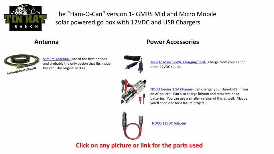
Power Accessories
Male to Male 12VDC Charging Cord- Charge from your car or other 12VDC source
NOCO Genius 3.5A Charger- Can charger your Ham-O-Can from an AC source. Can also charge lithium and resurrect dead batteries. You can use a smaller version of this as well. Maybe you’ll need one for a future project…
NOCO 12VDC Adapter
Antenna
SlimJim Antenna- One of the best options and probably the only option that fits inside the can. The original N9TAX.
Click on any picture or link for the parts used

The “Ham-O-Can” version 1- GMRS Midland Micro Mobile solar powered go box with 12VDC and USB Chargers
Goals of the Build • Provide a portable, reliable, and safe communications go box • Make the construction as easy as possible • Provide added utility in charging devices via USB or 12VDC. • Address the issues found in other DIY projects found on the internet. • Options for charging; solar, car, AC, or any 12VDC source.

• The first thing you are going to need to do is cut the plywood pieces. You can use any number of methods to do so, a table saw and miter saw would work the best, but you could also use a radial arm relic like I did or even a circular saw. The basic dimensions of the five pieces are as such: • Faceplate- 10 15/16” x 5 9/16” • Backplate- 10 15/16” x 5 9/16” • Bottomplate- 9 5/8” x 4 ¼” • Charge Controller Plate- 6 3/16” x 4 ¼” • Battery Holder- I used a scrap that was 1 ½” x 1 ¼”
• Next, use the template or the ammo can to mark a radius on the corners of the faceplate and backplate. Cut these with a jig saw.
• Using the template, mark and drill the (4) holes for the 6 inch bolts using a 5/16ths or 9/32nds drill bit. Try lining up both plates and drilling the holes at the same time through both pieces so they line up.
• Insert 6” Bolts in the back plate and use nuts to hole them in place. • On the Faceplate, using the template or measurements, drill holes for the USB/meter/12VDC charger using an 1 1/8th
Forstner bit, or drill a smaller pilot hole and cut out with a jig saw. Alternatively, you can place the mount on the faceplate and trace the holes. This is probably the most precision cut in the project.
Assembly instructions- to be followed using the video

Faceplate Hole Sizes
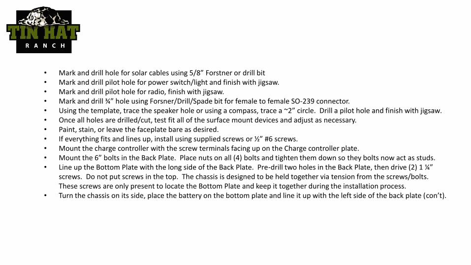
• Mark and drill hole for solar cables using 5/8” Forstner or drill bit • Mark and drill pilot hole for power switch/light and finish with jigsaw. • Mark and drill pilot hole for radio, finish with jigsaw. • Mark and drill ¾” hole using Forsner/Drill/Spade bit for female to female SO-239 connector. • Using the template, trace the speaker hole or using a compass, trace a ~2” circle. Drill a pilot hole and finish with jigsaw. • Once all holes are drilled/cut, test fit all of the surface mount devices and adjust as necessary. • Paint, stain, or leave the faceplate bare as desired. • If everything fits and lines up, install using supplied screws or ½” #6 screws. • Mount the charge controller with the screw terminals facing up on the Charge controller plate. • Mount the 6” bolts in the Back Plate. Place nuts on all (4) bolts and tighten them down so they bolts now act as studs. • Line up the Bottom Plate with the long side of the Back Plate. Pre-drill two holes in the Back Plate, then drive (2) 1 ¼”
screws. Do not put screws in the top. The chassis is designed to be held together via tension from the screws/bolts. These screws are only present to locate the Bottom Plate and keep it together during the installation process.
• Turn the chassis on its side, place the battery on the bottom plate and line it up with the left side of the back plate (con’t).

• (con’t)- place the charge controller plate with the charge controller facing away from the battery. Line it up with the left side of the Back Plate. Mark the location on the Back Plate and transfer the line to the back side. Using a small drill bit, pre-drill two holes in the back side of the back plate. Using two 1 ¼” screws, secure the charge controller plate to the back plate. This will keep the battery in place on two axis, the can itself will keep it in place on the left side, and the radio mount bracket will keep it in place on the right side.
• Place the Faceplate on the top of the chassis and temporarily tighten the nuts down to hold in in place. • Line up the radio mount so the radio can slide through the faceplate and lock into place. Mark a side of
the radio mount with a pencil. Take the Faceplate back off, line up the mount for the radio with the front of the bottom plate and the mark you just made and attach it using the supplied fasteners.
• Place the battery back in the “battery slot”. Place the 1 ½”x 1 ¼” battery holder on top of the battery, all the way to the left, and mark it on the charge controller plate. Pre-Drill a hole in the charge controller plate and mount it using a 1 ¼” screw. Note the battery cannot be removed unless you remove this screw. The battery is also now secure in all axis.
• Move on to the wiring portion.

Step 1: Connect the fusible link to the post on the fuse box using red wire to the positive (red) terminal on the battery. Connect negative (black) battery terminal to the 4 terminal ground bar. Leave the fuse out for now.
Wiring Instructions

Step 2: Connect a red wire from the fuse box terminal 1 to the positive terminal on the 12VDC plug. Connect a black wire to from the negative terminal to the 4 terminal ground lug.
Hints: This plug is always “hot” for
(2) reasons. First, it will be used as a method to charge the battery. Second, it doesn’t draw any power when not being used. It also doesn’t matter which terminal on the ground lug is used. Use which ever lug is convenient

Step 3: Connect a red wire from terminal 2 on the fuse box
to the ON side of the switch. Connect the red wire from the light on the switch AND another piece of wire to the ON terminal. Using a butt connector, run (1) wire to each the positive terminals on the USB connector and the volt meter. Run a dedicated black wire from the switch, the USB, and the volt meter to the 4 terminal ground block
OFF ON
Switch Light
Hints: This is the most difficult step in the whole process. If you can get past this, you are home free. You cannot daisy chain the USB and the meter, the butt connector in essence makes a parallel circuit to power the USB and the volt meter. On the “ON” side of the switch use the same connector to connect the red wire from the light and the red wire.

Step 4: Connect a red wire from terminal 3 on the
fuse block to the positive terminal #1 on the charge controller. Connect a black wire from negative terminal #1 to the 4 terminal ground bar. Connect the Renogy MC4 9 inch adapter wires, connecting positive from the panel to positive on the controller and negative to negative.

Step 5: take the power cable supplied with the midland radio and cut it, making sure to leave enough wire to reach the terminals. Connect the red wire to terminal 4 on the fuse block. Connect the black wire to the 4 terminal ground bar. Connect the coax pigtail jumper from the antenna out on the radio to the male to male PL-259 connector.

Step 6: Take a mono audio cable with 1/8” jacks and cut it to length so it will go from the radio to the speaker. Carefully strip the wire and solder the red wire to the larger blade on the speaker and the black wire to the smaller blade on the speaker.

This fuse holder comes with a 30 Amp fuse, suggest replacing with a 15 Amp fuse.
Terminal 1 (12VDC Plug)- Suggest 15 Amp Fuse Terminal 2 (USB, meter, and switch light)- Suggest 10 Amp Fuse Terminal 3 (Solar Charger)- Suggest 10 Amp fuse Terminal 4 (Radio)- Suggest 5 Amp fuse
Step 7: The moment of truth. Disconnect the negative battery lead and insert the suggested fuses. Once the fuses are installed, connect the negative battery lead and individually test all circuits.
Known Issues
• The Charge Controller will consume 4mA in stand by. This is a very low draw but will drain the battery in storage after some time. The solution is to remove the negative battery lead when the Ham-O-Can is in storage.