The GSM standard-N
49
Introduction 1. GSM Frequency Band Allocation 1.1 GSM frequency allocation 1.2 EGSM/RGSM frequency allocation 2. Multiple Access Technology 2.1 FDMA 2.2 TDMA 3. GSM network 3.1 The mobile station (MS) 3.1.1 Identifiers in the GSM Network 3.2 The base station subsystem (BSS) 3.2.1 The Base Transceiver Station (BTS) 3.2.2 The Base Station Controller (BSC) 3.3 The network subsystem 3.3.1 The Mobile Switching Center (MSC) 3.3.2 The Home Location Register (HLR) 3.3.3 The Visitor Location Register (VLR) 3.3.4 The Authentication Center (AuC) 3.3.5 The Equipment Identity Register (EIR) 3.3.6 Operation and Maintenance Center (OMC) 4. The Air Interface U m 4.1 Air interface for logical channel 4.2 Traffic channels on the air interface 4.3 Signaling channels on the air interface 4.3.1 The broadcast channels (BCH) 1
-
Upload
rohit-sharma -
Category
Documents
-
view
226 -
download
0
Transcript of The GSM standard-N
8/7/2019 The GSM standard-N
http://slidepdf.com/reader/full/the-gsm-standard-n 1/49
Introduction
1. GSM Frequency Band Allocation1.1 GSM frequency allocation
1.2 EGSM/RGSM frequency allocation
2. Multiple Access Technology2.1 FDMA2.2 TDMA
3. GSM network
3.1 The mobile station (MS)3.1.1 Identifiers in the GSM Network
3.2 The base station subsystem (BSS)3.2.1 The Base Transceiver Station (BTS)
3.2.2 The Base Station Controller (BSC)
3.3 The network subsystem3.3.1 The Mobile Switching Center (MSC)3.3.2 The Home Location Register (HLR)3.3.3 The Visitor Location Register (VLR)3.3.4 The Authentication Center (AuC)3.3.5 The Equipment Identity Register (EIR)3.3.6 Operation and Maintenance Center (OMC)
4. The Air Interface U m
4.1 Air interface for logical channel4.2 Traffic channels on the air interface
4.3 Signaling channels on the air interface4.3.1 The broadcast channels (BCH)
1
8/7/2019 The GSM standard-N
http://slidepdf.com/reader/full/the-gsm-standard-n 2/49
4.3.2 The Common Control Channel (CCCH)4.3.3 The Dedicated Control Channel (DCCH)
4.4 Burst formats
5. MSC-based interfaces5.1 MSC protocols5.2Data Transmission5.3Voice Coding
5.3.1Channel Coding5.3.2Interleaving5.3.3Encryption5.3.4Modulation and Demodulation5.3.5Timing advance
6. Mobile Terminated CallHandoverData Transmission OverviewDiscontinuous reception (DRX)Power control
7. System featuresRoaming
Multipath equalizationFrequency hoppingShort Message Service (SMS)Call Waiting (CW)Call Hold (CH)Call Forwarding (CF)Calling Line IDMobility Management (MM)Authentication
8. The Evolution Path for GSM
9. GSM glossary
2

8/7/2019 The GSM standard-N
http://slidepdf.com/reader/full/the-gsm-standard-n 3/49
INTRODUCTION
The GSM standard (Global System for Mobile Communications) formobile telephony was introduced in the mid-1980 s. Today, GSM is themost popular mobile radio standard in the world.
Nowadays, when we speak of GSM, we usually mean “original” GSMalso known as GSM900 since 900 MHz was the original frequency band.
Which Technology used before GSM?
Before GSM networks there were public mobile radio networks(cellular).
They normally used analog technologies, which varied from country tocountry and from manufacturer to another.
These analog networks did not comply with any uniform standard.
There was no way to use a single mobile phone from one country toanother.
The speech quality in most networks was not satisfactory.
GSM became popular very quickly because it provided improvedspeech quality and, through a uniform international standard, made itpossible to use a single telephone number and mobile unit around theworld.
European Telecommunications Standardization Institute (ETSI) adoptedthe GSM standard in 1991, and GSM is now used in 135 countries.
3
8/7/2019 The GSM standard-N
http://slidepdf.com/reader/full/the-gsm-standard-n 4/49
The benefits of GSM
Support for international roaming
Distinction between user and device identification
Excellent speech quality
Wide range of services
Interworking (e.g. with ISDN, DECT)
Extensive security features
Telephony
Asynchronous and synchronous data services
Access to packet data network
Telemetric services (SMS, fax, video, text, etc.)
Many value-added features(Call forwarding, caller ID, and voice mailbox)
E-mail and internet connections
4

8/7/2019 The GSM standard-N
http://slidepdf.com/reader/full/the-gsm-standard-n 5/49
1. GSM Frequency BandAllocation
GSM cellular system can be divided into GSM 900M, GSM 1800M &GSM 1900 according to frequency band, with carrier frequency intervalof 200 KHz and up and down frequencies as follows:
1.1 GSM frequency allocation
Frequency
Band(MHz)
BW
(MHz)
Frequenc
y number
Carrierfreq.
number (pair)GSM900
Up 890–915Down 935–960 25 1–124 124
GSM1800
Up 1710–1785Down 1805–1880 75 512–885 374
“Up ” and “ down ” are classified according to base station.
Base station transmitting - mobile station receiving is “down”; mobile
station transmitting - base station receiving is up.
With the expanding services, GSM protocol adds EGSM (expandedGSM frequency band) and RGSM (expanded GSM frequency bandincluding railway service) to the original GSM900 frequency band. Thefrequency band allocation is as follows:
1.2 EGSM/RGSM frequency allocation
Frequencyband(MHz)
BW(MHz)
FrequencyNumber
Carrierfreq.number(pair)
EGSMUp 880–915Down 925–960
350–124
975–1023174
5
8/7/2019 The GSM standard-N
http://slidepdf.com/reader/full/the-gsm-standard-n 6/49
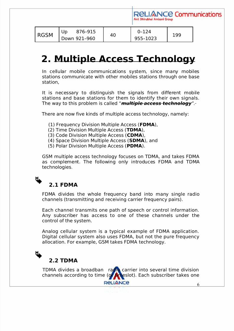
RGSMUp 876–915Down 921–960
400–124
955–1023199
2. Multiple Access TechnologyIn cellular mobile communications system, since many mobilesstations communicate with other mobiles stations through one basestation,
It is necessary to distinguish the signals from different mobilestations and base stations for them to identify their own signals.
The way to this problem is called “ multiple access technology ”.
There are now five kinds of multiple access technology, namely:(1) Frequency Division Multiple Access ( FDMA ),(2) Time Division Multiple Access ( TDMA ),(3) Code Division Multiple Access ( CDMA ),(4) Space Division Multiple Access ( SDMA ), and(5) Polar Division Multiple Access ( PDMA ).
GSM multiple access technology focuses on TDMA, and takes FDMAas complement. The following only introduces FDMA and TDMAtechnologies.
2.1 FDMA
FDMA divides the whole frequency band into many single radiochannels (transmitting and receiving carrier frequency pairs).
Each channel transmits one path of speech or control information.Any subscriber has access to one of these channels under thecontrol of the system.
Analog cellular system is a typical example of FDMA application.Digital cellular system also uses FDMA, but not the pure frequencyallocation. For example, GSM takes FDMA technology.
2.2 TDMA
TDMA divides a broadband radio carrier into several time divisionchannels according to time (or timeslot). Each subscriber takes one
6

8/7/2019 The GSM standard-N
http://slidepdf.com/reader/full/the-gsm-standard-n 7/49
timeslot and sends or receives signals only in the specified timeslot. TDMA is applied in digital cellular system and GSM.
GSM adopts a technology combined with FDMA andTDMA.
3. GSM network
A GSM network can be divided into three groups.
The mobile station (MS), The base station subsystem (BSS) and The network subsystem.
7

8/7/2019 The GSM standard-N
http://slidepdf.com/reader/full/the-gsm-standard-n 8/49
8

8/7/2019 The GSM standard-N
http://slidepdf.com/reader/full/the-gsm-standard-n 9/49
8/7/2019 The GSM standard-N
http://slidepdf.com/reader/full/the-gsm-standard-n 10/49
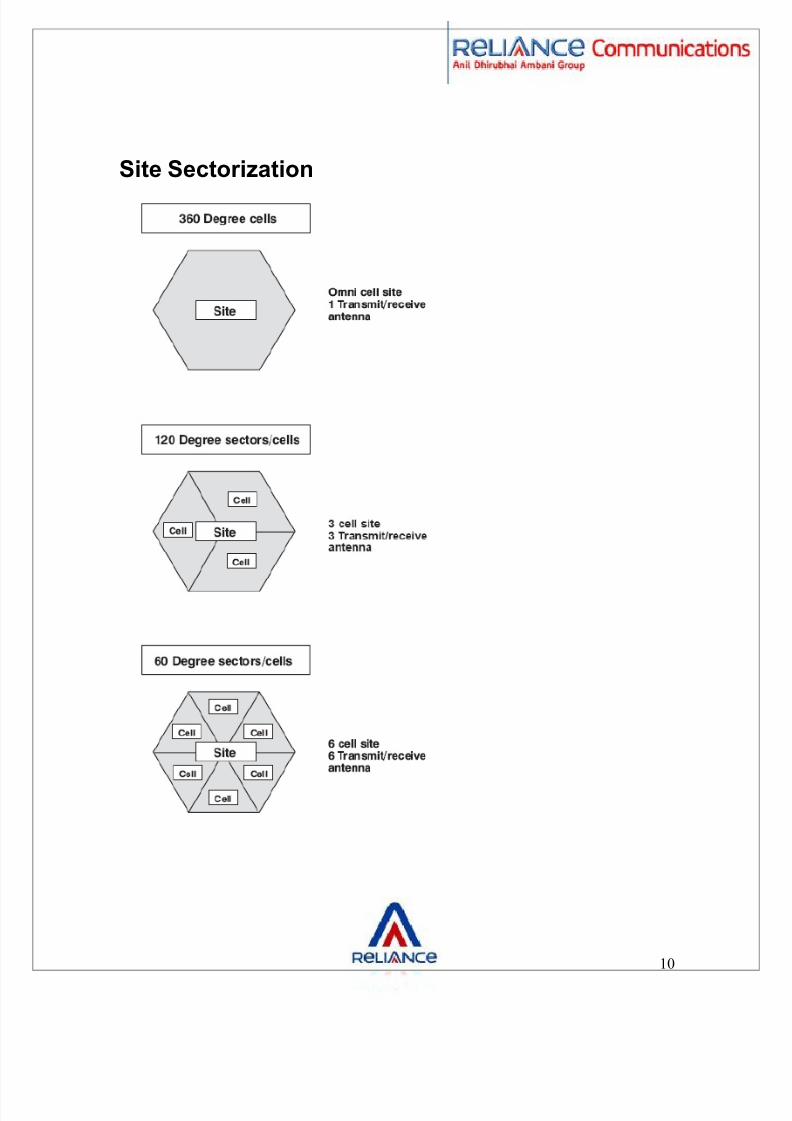
Site Sectorization
10
8/7/2019 The GSM standard-N
http://slidepdf.com/reader/full/the-gsm-standard-n 11/49
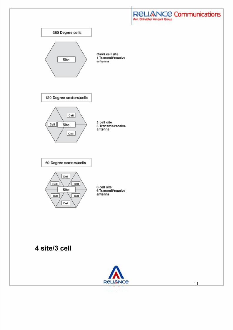
4 site/3 cell
11
8/7/2019 The GSM standard-N
http://slidepdf.com/reader/full/the-gsm-standard-n 12/49
12
8/7/2019 The GSM standard-N
http://slidepdf.com/reader/full/the-gsm-standard-n 13/49
They are characterized as follows:
3.1 The mobile station (MS)
A mobile station may be referred to as a “handset”, a “mobile”, a“portable Terminal” or “mobile equipment” ( ME ).
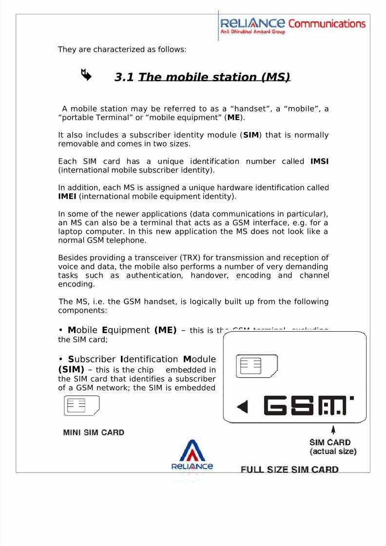
It also includes a subscriber identity module ( SIM ) that is normallyremovable and comes in two sizes.
Each SIM card has a unique identification number called IMSI(international mobile subscriber identity).
In addition, each MS is assigned a unique hardware identification calledIMEI (international mobile equipment identity).
In some of the newer applications (data communications in particular),an MS can also be a terminal that acts as a GSM interface, e.g. for alaptop computer. In this new application the MS does not look like anormal GSM telephone.
Besides providing a transceiver (TRX) for transmission and reception of voice and data, the mobile also performs a number of very demandingtasks such as authentication, handover, encoding and channel
encoding. The MS, i.e. the GSM handset, is logically built up from the followingcomponents:
• Mobile Equipment (ME) – this is the GSM terminal, excludingthe SIM card;
• S ubscriber Identification M odule(SIM) – this is the chip embedded in
the SIM card that identifies a subscriberof a GSM network; the SIM is embeddedin the SIM card.
13

8/7/2019 The GSM standard-N
http://slidepdf.com/reader/full/the-gsm-standard-n 14/49
3.1.1 Identifiers in the GSM Network GSM uses several identifiers for the routing of calls, identifyingsubscribers (e.g. for charging), locating the HLR, identifyingequipment, etc. Some of these identifiers play an important role forSubscriber Identity
The International Mobile S ubscriber Identity (IMSI) is embedded onthe SIM card and is used to identify a subscriber. The IMSI is alsocontained in the subscription data in the HLR. The IMSI is used foridentifying a subscriber for various processes in the GSM network.
Figure 1.4 shows the format of the IMSI.
• M obile Country Code (MCC) – The MCC identifies the countryfor mobile networks. The MCC is not used for call establishment. TheMCC values are allocated and published by the ITU-T.
• M obile N etwork Code (MNC) – The MNC identifies the mobilenetwork within a mobile country (as identified by MCC). MCC and MNCtogether identify a PLMN ( P ublic Land M obile N etwork). TheMNC may be two or three digits in length. Common practice is that,within a country (as identified by MCC), all MNC’s are either two orthree digits.
14

8/7/2019 The GSM standard-N
http://slidepdf.com/reader/full/the-gsm-standard-n 15/49
• M obile S ubscriber Identification N umber (MSIN) – TheMSIN is
the subscriber identifier within a PLMN.
15
8/7/2019 The GSM standard-N
http://slidepdf.com/reader/full/the-gsm-standard-n 16/49
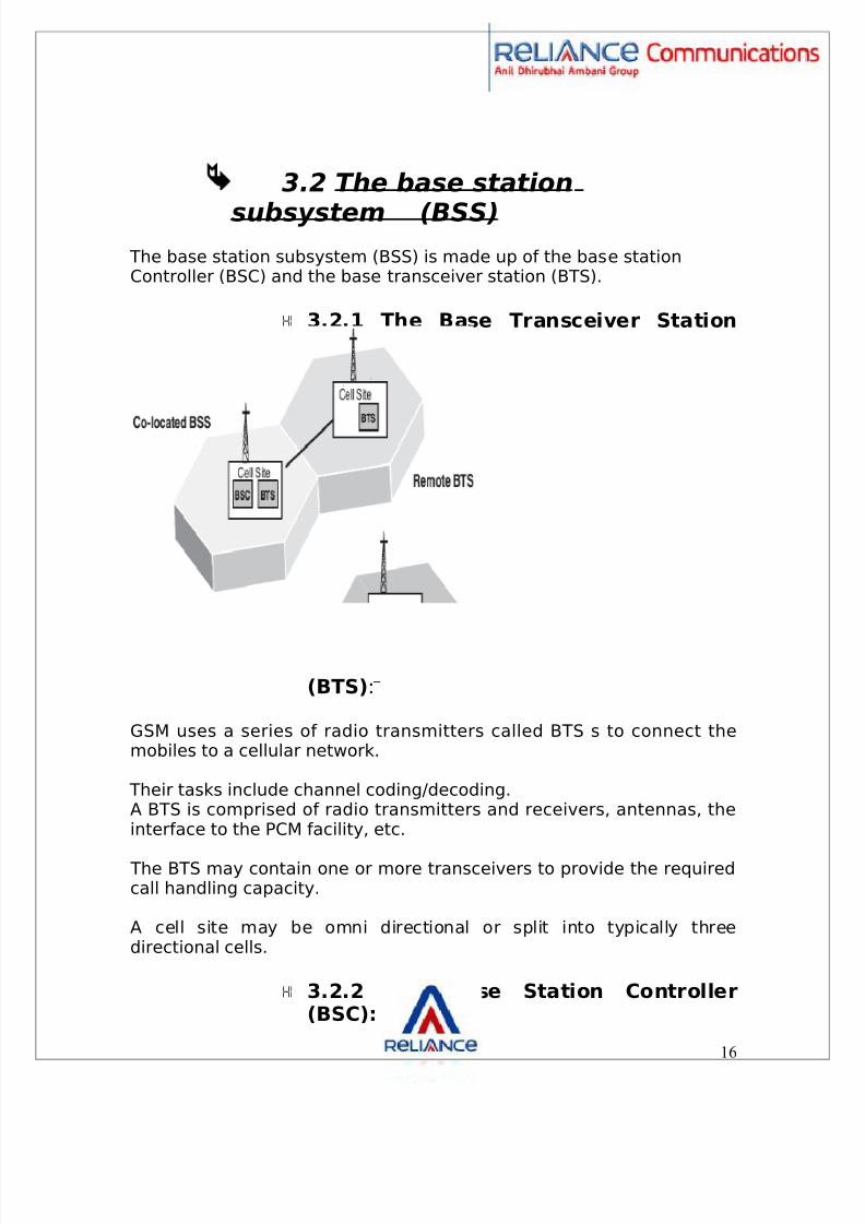
3.2 The base station
subsystem (BSS) The base station subsystem (BSS) is made up of the base stationController (BSC) and the base transceiver station (BTS).
3.2.1 The Base Transceiver Station
(BTS) :
GSM uses a series of radio transmitters called BTS s to connect themobiles to a cellular network.
Their tasks include channel coding/decoding.A BTS is comprised of radio transmitters and receivers, antennas, theinterface to the PCM facility, etc.
The BTS may contain one or more transceivers to provide the requiredcall handling capacity.
A cell site may be omni directional or split into typically threedirectional cells.
3.2.2 The Base Station Controller(BSC):
16
8/7/2019 The GSM standard-N
http://slidepdf.com/reader/full/the-gsm-standard-n 17/49
A group of BTSs are connected to a particular BSC which manages theradio resources for them.
Today's new and intelligent BTSs have taken over many tasks that
were previously handled by the BSCs.
The primary function of the BSC is call maintenance.
The mobile stations normally send a report of their received signalstrength to the BSC every 480 ms.
With this information the BSC decides to initiate handovers to othercells, change the BTS transmitter power, etc.
3.3 The network subsystem
3.3.1 The Mobile Switching Center(MSC):
Acts like a standard exchange in a fixed network and additionallyprovides all the functionality needed to handle a mobile subscriber.
The main functions are registration, authentication, location updating,and handovers and call routing to a roaming subscriber.
The signaling between functional entities (registers) in the networksubsystem uses Signaling System.
If the MSC also has a gateway function for communicating with othernetworks, it is called Gateway MSC ( GMSC ).
3.3.2 The Home Location Register(HLR):
A database used for management of mobile subscribers. It stores theinternational mobile subscriber identity ( IMSI ), mobile station ISDNnumber ( MSISDN ) and current visitor location register ( VLR ) address.
17
8/7/2019 The GSM standard-N
http://slidepdf.com/reader/full/the-gsm-standard-n 18/49
The main information stored there concerns the location of eachmobile station in order to be able to route calls to the mobilesubscribers managed by each HLR.
The HLR also maintains the services associated with each MS. One HLR
can serve several MSCs.
3.3.3 The Visitor Location Register(VLR):
Contains the current location of the MS and selected administrativeinformation from the HLR, necessary for call control and provision of the subscribed services, for each mobile currently located in thegeographical area controlled by the VLR.
A VLR is connected to one MSC and is normally integrated into theMSC's hardware.
3.3.4 The Authentication Center(AuC):
A protected database that holds a copy of the secret key stored in
each subscriber's SIM card, which is used for authentication andencryption over the radio channel.
The AuC provides additional security against fraud. It is normallylocated close to each HLR within a GSM network.
3.3.5 The Equipment Identity Register(EIR):
The EIR is a database that contains a list of all valid mobile stationequipment within the network, where each mobile station is identifiedby its international mobile equipment identity (IMEI).
The EIR has three databases:White list: for all known, good IMEIsBlack list: for bad or stolen handsetsGrey list: for handsets/IMEIs that are uncertain
18
8/7/2019 The GSM standard-N
http://slidepdf.com/reader/full/the-gsm-standard-n 19/49
3.3.6 Operation and MaintenanceCenter (OMC):
The OMC is a management system that oversees the GSM functionalblocks. The OMC assists the network operator in maintainingsatisfactory operation of the GSM network.
Hardware redundancy and intelligent error detection mechanisms helpprevent network down-time.
The OMC is responsible for controlling and maintaining the MSC, BSCand BTS. It can be in charge of an entire public land mobile network(PLMN ) or just some parts of the PLMN.
Providing voice or data transmission quality over the radio link is onlypart of the function of a cellular mobile network.
A public communications system also needs solid security mechanismsto prevent misuse by third parties.
Security functions such as authentication, encryption and the use of Temporary Mobile Subscriber Identities ( TMSI s) are an absolute must.
Within a GSM network, different protocols are needed to enable theflow of data and signaling between different GSM subsystems.
4. The Air Interface U m
The air interface for GSM is known as the Um interface.
The International Telecommunication Union ( ITU ), which managesinternational allocation of radio spectrum (among many otherfunctions), has allocated the following bands:
GSM900 :
Uplink: 890-915 MHz (MS to BS)Downlink: 935-960 MHz (BS to MS).
GSM1800:Uplink: 1710-1785 MHz (MS to BS)Downlink: 1805-1880 MHz (BS to MS).
GSM1900 :Uplink: 1850-1910 MHz (MS to BS)
19

8/7/2019 The GSM standard-N
http://slidepdf.com/reader/full/the-gsm-standard-n 20/49
Downlink: 1930-1990 MHz (BS to MS).
The basic conception of GSM in terms of radio path is burst.
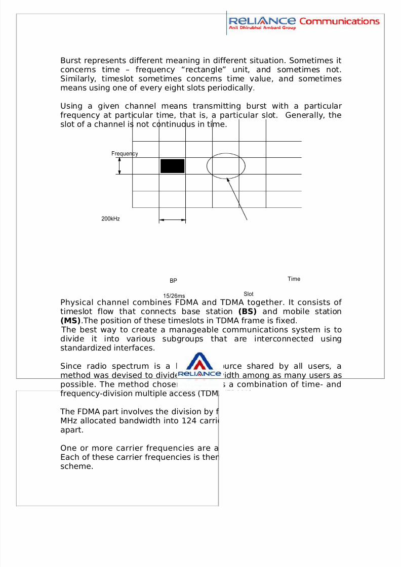
Burst is a transmission unit consists of over one hundred of modulation bits. It has a duration limit and takes a limited radiofrequency. They are exported in time and frequency window which iscalled slot .
To be specific, in system frequency band, central frequency of slot isset in every 200 KHz (in FDMA). Slot occurs periodically in each 15/26ms, which is about 0.577 ms (in TDMA).
The interval between two slots is called timeslot . Its duration is usedas time unit, called burst period (BP) .
Time/frequency map illustrates the concept of slot. Each slot isexpressed as one little rectangle with 15/26ms length and 200 KHzwidth.
In Figure, the 200 KHz bandwidth in GSM is called frequency slot ,equal to radio frequency channel in GSM protocol.
20
8/7/2019 The GSM standard-N
http://slidepdf.com/reader/full/the-gsm-standard-n 21/49
Burst represents different meaning in different situation. Sometimes itconcerns time – frequency “rectangle” unit, and sometimes not.Similarly, timeslot sometimes concerns time value, and sometimesmeans using one of every eight slots periodically.
Using a given channel means transmitting burst with a particularfrequency at particular time, that is, a particular slot. Generally, theslot of a channel is not continuous in time.
Physical channel combines FDMA and TDMA together. It consists of timeslot flow that connects base station (BS) and mobile station(MS) .The position of these timeslots in TDMA frame is fixed.
The best way to create a manageable communications system is todivide it into various subgroups that are interconnected usingstandardized interfaces.
Since radio spectrum is a limited resource shared by all users, amethod was devised to divide the bandwidth among as many users aspossible. The method chosen by GSM is a combination of time- and
frequency-division multiple access (TDMA/FDMA). The FDMA part involves the division by frequency of the (maximum) 25MHz allocated bandwidth into 124 carrier frequencies spaced 200 kHzapart.
One or more carrier frequencies are assigned to each base station.Each of these carrier frequencies is then divided in time, using a TDMAscheme.
21
Frequenc y
200kHz
BP
15/26msSlot
Time
8/7/2019 The GSM standard-N
http://slidepdf.com/reader/full/the-gsm-standard-n 22/49
The fundamental unit of time in this TDMA scheme is called a burstperiod and it lasts approx. 0.577 ms. Eight burst periods are groupedinto a TDMA frame (approx. 4.615 ms), which forms the basic unit forthe definition of logical channels. One physical channel is one burstperiod per TDMA frame.
4.1 Air interface for logical channel
In real networking, each cell has several carrier frequencies and eachfrequency has eight timeslots, proving eight basic physical channels.
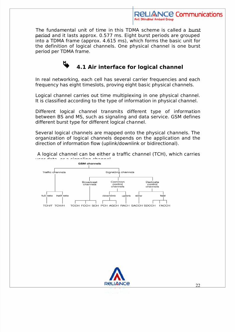
Logical channel carries out time multiplexing in one physical channel.It is classified according to the type of information in physical channel.
Different logical channel transmits different type of informationbetween BS and MS, such as signaling and data service. GSM definesdifferent burst type for different logical channel.
Several logical channels are mapped onto the physical channels. Theorganization of logical channels depends on the application and thedirection of information flow (uplink/downlink or bidirectional).
A logical channel can be either a traffic channel (TCH), which carriesuser data, or a signaling channel.
22

8/7/2019 The GSM standard-N
http://slidepdf.com/reader/full/the-gsm-standard-n 23/49
4.2 Traffic channels on the air interface
A traffic channel (TCH) is used to carry speech and data traffic. Trafficchannels are defined using a 26-frame multiframe, or group of 26
TDMA frames. The length of a 26-frame Multiframe is 120 ms, which ishow the length of a burst period is defined (120 ms divided by 26frames divided by 8 burst periods per frame).
Out of the 26 frames, 24 are used for traffic, 1 is used for the slowassociated control channel ( SACCH ) and 1 is currently unused.
23
8/7/2019 The GSM standard-N
http://slidepdf.com/reader/full/the-gsm-standard-n 24/49
TCHs for the uplink and downlink are separated in time by 3 burstperiods, so that the MS does not have to transmit and receivesimultaneously, thereby simplifying the electronic circuitry. Thismethod permits complex antenna & duplex filters to be avoided and
thus helps to cut power consumption.
In addition to these full-rate TCHs (TCH/F, 22.8 kbit/s), half-rate TCHs(TCH/H, 11.4 kbit/s) are also defined. Half-rate TCHs double thecapacity of a system effectively by making it possible to transmit twocalls in a single channel.
4.3 Signaling channels on the airinterface
The signaling channels on the air interface are used for callestablishment, paging, call maintenance, synchronization, etc.
There are 3 groups of signaling channels:-
4.3.1 The broadcast channels (BCH):
Carry only downlink information and are responsible mainly forsynchronization and frequency correction.
This is the only channel type enabling point-to-multipointcommunications in which short messages are simultaneouslytransmitted to several mobiles.
The BCHs include the following channels:
The broadcast control channel (BCCH):
General information, cell specific; e.g. local area code (LAC), networkoperator, access parameters, list of neighboring cells, etc.
The MS receives signals via the BCCH from many BTSs within the samenetwork and/or different networks.
The frequency correction channel (FCCH):
24
8/7/2019 The GSM standard-N
http://slidepdf.com/reader/full/the-gsm-standard-n 25/49
Downlink only; correction of MS frequencies; transmission of frequencystandard to MS;
It is also used for synchronization of an acquisition by providing theboundaries between timeslots and the position of the first timeslot of a
TDMA frame.
The synchronization channel (SCH):
Downlink only; frame synchronization (TDMA frame number) andidentification of base station. The valid reception of on SCH burst willprovide the MS with all the information needed to synchronize with aBTS.
4.3.2 The Common Control Channels (CCCH):
A group of uplink and downlink channels between the MS card and theBTS. These channels are used to convey information from the networkto MSs and provide access to the network.
The CCCHs include the following channels:
¬ The Paging Channel (PCH):
Downlink only; the MS is informed by the BTS for incoming calls via thePCH.
The Access Grant Channel (AGCH):
Downlink only; BTS allocates a TCH or SDCCH to the MS, thus allowingthe MS access to the network.
The Random Access Channel (RACH):
Uplink only; allows the MS to request an SDCCH in response to a pageor due to a call; the MS chooses a random time to send on thischannel.
The PCH and AGCH are transmitted in one channel called the pagingand access grant channel (PAGCH). They are separated by time.
25
8/7/2019 The GSM standard-N
http://slidepdf.com/reader/full/the-gsm-standard-n 26/49
4.3.3 The Dedicated Control Channels(DCCH):
Responsible for e.g. roaming, handovers, encryption, etc. The DCCHsinclude the following channels:
The Stand-alone Dedicated Control Channel(SDCCH):
Communications channel between MS and the BTS; signalingduring call setup before a traffic channel (TCH) is allocated;
The Slow Associated Control Channel (SACCH):
Transmits continuous measurement reports (e.g. field strengths) in
parallel to operation of a TCH or SDCCH; needed, e.g. for handoverdecisions; always allocated to a TCH or SDCCH; needed for “non-urgent” procedures,
E.g. for radio measurement data, power control (downlink only), timingadvance, etc.; always used in parallel to a TCH or SDCCH.
The Fast Associated Control Channel (FACCH):
Similar to the SDCCH, but used in parallel to operation of the TCH; if the data rate of the SACCH is insufficient, “borrowing mode” is used:
Additional bandwidth is borrowed from the TCH; this happens formessages associated with call establishment authentication of thesubscriber, handover decisions, etc.
Almost all of the signaling channels use the “normal burst” format(Burst formats), except for the RACH (Random Access Burst), FCCH(Frequency Correction Burst) and SCH (Synchronization Burst)channels.
4.4 Burst formats
Burst is the message layout of a timeslot in TDMA channel, whichmeans each burst is sent to a timeslot of TDMA frame.
26

8/7/2019 The GSM standard-N
http://slidepdf.com/reader/full/the-gsm-standard-n 27/49
Different message in the burst determines its layout.
A timeslot is a 576 ms time interval, i.e. 156.25 bits duration, and itsphysical contents are known as a burst. Five different types of bursts
exist in the system. They are distinguished by different TDMA framedivisions.
The normal burst (NB) : Used to carry information on trafficand control channels, except for RACH. It contains 116 encryptedbits.
The frequency correction burst (FB) : Used for frequencysynchronization of the mobile. The contents of this burst areused to calculate unmodulated, sinusoidal oscillation, onto whichthe synthesizer of the mobiles is clocked.
The synchronization burst (SB) : Used for timesynchronization of the mobile. It contains a long trainingsequence and carries the information of a TDMA frame number.
The access burst (AB) : Used for random access andcharacterized by a longer guard period (256 ms) to allow forburst transmission from a mobile that does not know the correcttiming advance at the first access to a network (or afterhandover).
The dummy burst (DB) : Transmitted as a filler in unusedtimeslots of the carrier; does not carry any information but hasthe same format as a normal burst (NB).
5. MSC-based interfaces
27

8/7/2019 The GSM standard-N
http://slidepdf.com/reader/full/the-gsm-standard-n 28/49
All of the interfaces around the MSC use SS7-based protocols. The B, C,D, F and G interfaces are referred to as MAP interfaces. These connecteither the MSC to registers or registers to other registers.
The E interface supports the MAP protocol and calls setup protocols(ISUP/ TUP). This interface connects one MSC to another MSC within thesame network or to another network's MSC.
They are designated as follows:
B interface: between MSC and VLR (use MAP/TCAP protocols)C interface: between MSC and HLR (MAP/TCAP)D interface: between HLR and VLR (MAP/TCAP)E interface: between two MSCs (MAP/TCAP + ISUP/TUP)F interface: between MSC and EIR (MAP/TCAP)
G interface: between VLRs (MAP/TCAP).
Fixed network interfaces:Via TUP protocol: between MSC and analog/digital networksVia ISUP protocol: between MSC and analog/digital networks &provides more features than TUPVia INAP protocol: between MSC and IN.
The SCCP protocol provides connectionless message transport to andfrom the GSM network databases for TCAP and MAP messaging. Here,two connection types are also distinguished:
Circuit-related call control: Related to ISUP and TUPNon circuit-related call control: The mobile application part (MAP)protocol is used here, allowing implementation of functions suchas location updating/roaming, SMS delivery, handover,authentication and incoming call routing information. The MAPprotocol uses the transaction capability application part (TCAP)protocol to transfer real-time information (between MSCs, HLRsand VLRs).
28

8/7/2019 The GSM standard-N
http://slidepdf.com/reader/full/the-gsm-standard-n 29/49
5.1 MSC protocols:-
MAP (Mobile Application Part):
Used to control queries to the different databases in the mobileradio network (HLR, VLR and EIR). MAP responsibilities includeaccess and location management
(E.g. where is the called subscriber currently?), MSC-MSC handover,security functions, O&M, SMS and supplementary services.
TCAP (Transaction Capabilities Application Part):
Provides universal calls and functions for handling requests todistributed application processes.
ISUP (ISDN User Part):
Controls interworking (e.g. call setup/takedown) between PLMNsand other networks, and provides the same basic functionalities as
TUP.
INAP (Intelligent Network Application Part):
Implements intelligent supplementary services (e.g. free call, time-dependent routing functions in a central service center).
TUP (Telephone User Part):
Implements interworking between PLMNs and other networks.TUP isnormally used to provide international connections and is slowlybeing replaced by ISUP.
5.2 Data TransmissionRadio channel has totally different characteristics from wired channel.Radio channel has a strong time-varying characteristic.
It has a high error rate when the signal is influenced by interferences,multipath fading, or shadow fading. In order to solve these problems, itis necessary to protect the signals through a series of transformationand inverse transformation from original subscriber data or signaling
29

8/7/2019 The GSM standard-N
http://slidepdf.com/reader/full/the-gsm-standard-n 30/49
data to the information carried by radio wave and then to subscriberdata or signaling data.
These transformations include channel coding and decoding,interleaving and de-interleaving, burst formatting, encryption anddecryption, modulation and demodulation. See
FIG: - Forward and reverse data transmission process
5.3 Voice Coding
Modern digital communication system usually uses voice compressiontechnology. GSM takes tone and noise from human throat as well asthe mouth and tongue filter effect of acoustics as voice encoder toestablish a model. The model parameters transmit through TCHchannel.
30

8/7/2019 The GSM standard-N
http://slidepdf.com/reader/full/the-gsm-standard-n 31/49
Voice encoder divides voice into several 20 ms voice blocks andsamples each block with 8 kHz, so each block has 160 samples.
5.3.1 Channel Coding
Channel coding is used to improve transmission quality and removethe influence of interferential factors on signals at the price of increasing bits and information.
The basic way of coding is adding some redundant information to theoriginal data. The added data is calculated on the basis of original datawith certain rules.
Different code is used in different transmission mode. In practice,several coding schemes are always combined together. Common
coding schemes include block convolutional code, error correctingcyclic code and parity code.
In GSM, each logical channel has its own coding and interleavingmode, but the principle is trying to form a unified coding structure.
Encode information bit into a unified block code consistingof information bits and parity check bits.Encode block code into convolutional code and formcoding bits (usually 456 bits).Reassemble and interleave coding bits and add a stealing
flag to form interleaving bits.
All these operations are based on block. The block size depends onchannel type. After channel coding, all channels (except RACH andSCH) are made of 464-bit block, that is, 456 coded information bitsplus 8-bit header (header is used to distinguish TCH and FACCH).
In TCH/F voice service; this block carries one speech frame of Information. In control channel, this block usually carries one piece of information.
In TCH/H voice service, speech information is transmitted by a block of 228 coded bits block.For FACCH, each block of 456 coded information bits is divided intoeight sub blocks.
The first four sub blocks are transmitted by even bits of the fourtimeslots borrowed from the continuous frames of TCH, and the restfour sub blocks borrows odd bits of the four timeslots from the fourcontinuous frames delayed for two or four frames after the first frame.
31

8/7/2019 The GSM standard-N
http://slidepdf.com/reader/full/the-gsm-standard-n 32/49
5.3.2 Interleaving
If speech signal is modulated and transmitted directly after channelcoding, due to parametric variation of mobile communication channel,the long trough of deep feeding will affect the succeeding bits, leading
to error bit strings.
That is to say, after coding, speech signal turns into sequential frames,while in transmission, error bits usually occur suddenly, which willaffect the accuracy of continuous frames.
Channel coding only works for detection and correction of signal erroror short error string. Therefore, it is hoped to find a way to separatethe continuous bits in a message, that is, to transmit the continuousbits in a discontinuous mode so as to change the error channel intodiscrete channel.
Therefore, even if an error occurs, it is only about a single or very shortbit stream and will not interrupt the decoding of the entire burst oreven the entire information block.
Channel coding will correct the error bit under such circumstances. This method is called interleaving technology.
Interleaving technology is the most effective code grouping method toseparate error codes.
The essence of interleaving is to disperse the b bits into n bursts inorder to change the adjacent relationship between bits. Greater nvalue leads to better transmission performance but longertransmission delay.
Therefore, these two factors must be considered in interleaving.
Interleaving is always related to the use of channel. GSM adoptssecondary interleaving method.
After channel coding, The 456 bits are divided into eight groups; each
group contains 57 bits. This is the first interleaving, also calledinternal interleaving .After first interleaving, the continuity of information in a group isbroken. As one burst contains two groups of 57-bit voice information, if the two-group 57 bits of a 20 ms voice block after first interleaving areinserted to the same burst, the loss of this burst will lead to 25% lossof bits for this 20 ms voice block. Channel coding cannot restore somuch loss.
32
8/7/2019 The GSM standard-N
http://slidepdf.com/reader/full/the-gsm-standard-n 33/49
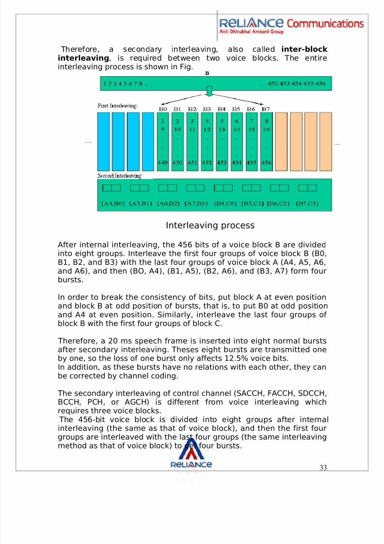
Therefore, a secondary interleaving, also called inter-block interleaving , is required between two voice blocks. The entireinterleaving process is shown in Fig.
Interleaving process
After internal interleaving, the 456 bits of a voice block B are dividedinto eight groups. Interleave the first four groups of voice block B (B0,B1, B2, and B3) with the last four groups of voice block A (A4, A5, A6,and A6), and then (BO, A4), (B1, A5), (B2, A6), and (B3, A7) form fourbursts.
In order to break the consistency of bits, put block A at even positionand block B at odd position of bursts, that is, to put B0 at odd positionand A4 at even position. Similarly, interleave the last four groups of block B with the first four groups of block C.
Therefore, a 20 ms speech frame is inserted into eight normal burstsafter secondary interleaving. Theses eight bursts are transmitted oneby one, so the loss of one burst only affects 12.5% voice bits.In addition, as these bursts have no relations with each other, they canbe corrected by channel coding.
The secondary interleaving of control channel (SACCH, FACCH, SDCCH,BCCH, PCH, or AGCH) is different from voice interleaving whichrequires three voice blocks.
The 456-bit voice block is divided into eight groups after internalinterleaving (the same as that of voice block), and then the first fourgroups are interleaved with the last four groups (the same interleavingmethod as that of voice block) to get four bursts.
33

8/7/2019 The GSM standard-N
http://slidepdf.com/reader/full/the-gsm-standard-n 34/49
Interleaving is an effective way to avoid interference, but it has a longdelay. In the transmission of a 20 ms voice block, the delay period is(9*8)-7=65 bursts (SACCH occupying one burst), which is 37.5 ms.
Therefore, MS and trunk circuit have echo cancellers added to removethe echo due to delay.
5.3.3 Encryption
Security is a very important feature in digital transmission system.GSM provides high security through transmission encryption. This kindof encryption can be used in voice, user data, and signaling. It is usedfor normal burst only and has nothing to do with data type.
5.3.4 Modulation and Demodulation
Modulation and demodulation is the last step of signal processing. GSM
modulation adopts GMSK technology with BT being 0.3 at the speed of 270.833 Kbit/s and Viterbi algorithm.
The function of modulation is to add a certain feature toelectromagnetic wave according to the rules. This feature is the datato transmit. In GSM, the phase of electromagnetic field bears theinformation.
The function of demodulation is to receive signals and restore the datain a modulated electromagnetic wave. A binary numeral has to bechanged into a low-frequency modulated signal first, and then into an
electromagnetic wave. Demodulation is the reverse process of modulation.
5.3.5 Timing advance
Signal transmission has a delay. If the MS moves away from BTS duringcalling, the signal from BTS to MS will be delayed, so will the signalfrom MS to BTS. If the delay is too long, the signal in one timeslot fromMS cannot be correctly decoded, and this timeslot may even overlapwith the timeslot of the next signal from other MS, leading to inter-timeslot interference.
Therefore, the report header carries the delay value measured by MS.BTS monitors the arrive time of call and send command to MS with thefrequency of 480 ms, prompting MS the timing advance (TA) value. Therange of this value is 0–63(0–233 us), and the maximum coverage areais 35km. The calculation is as follows:
1/2×3.7us/bit×63bit*c=35km
34

8/7/2019 The GSM standard-N
http://slidepdf.com/reader/full/the-gsm-standard-n 35/49
3.7us/bit is the duration per bit (156/577); 63bit is the maximum bit fortime coordination; c is light velocity (transmission rate of signal); 1/2 isrelated to the round-trip of signal.
According to the preceding description, 1bit to 554 m, due to the
influence of multi-path transmission and the accuracy of MSsynchronization, TA error may be about 3 bits (1.6km).
Sometimes a greater coverage area is required, such as in coastalareas. Therefore, the number of channels that each TRX contains mustbe reduced. The method is to bind odd and even timeslots, so thereare only four channels (0/1, 2/3, 4/5, and 6/7) for each TDMA frame inextended cell. Allocate channels 0, 2, 4, and 6 to MS.
Within 35 KM around BTS, the TA value of MS is in the normal range 0-63; for the area beyond 35 KM, TA value stays at 63.
This technology is called extended cell technology . The maximumvalue of TA in BTS measurement report is 63+156.25=219.25 bit, sothe maximum radius of coverage area is:
1/2×3.7us× (63+156.25) ×3×108m/s=120km
Principle of dual timeslot extended cell
The principle of dual timeslot extended cell is shown in Fig. In realscheme, in order to improve the utilization of TRX, both common TRXsand dual timeslot TRXs can be included. BCCH must be in dual timeslot
TRX to receive random access from any area.
35

8/7/2019 The GSM standard-N
http://slidepdf.com/reader/full/the-gsm-standard-n 36/49
8/7/2019 The GSM standard-N
http://slidepdf.com/reader/full/the-gsm-standard-n 37/49
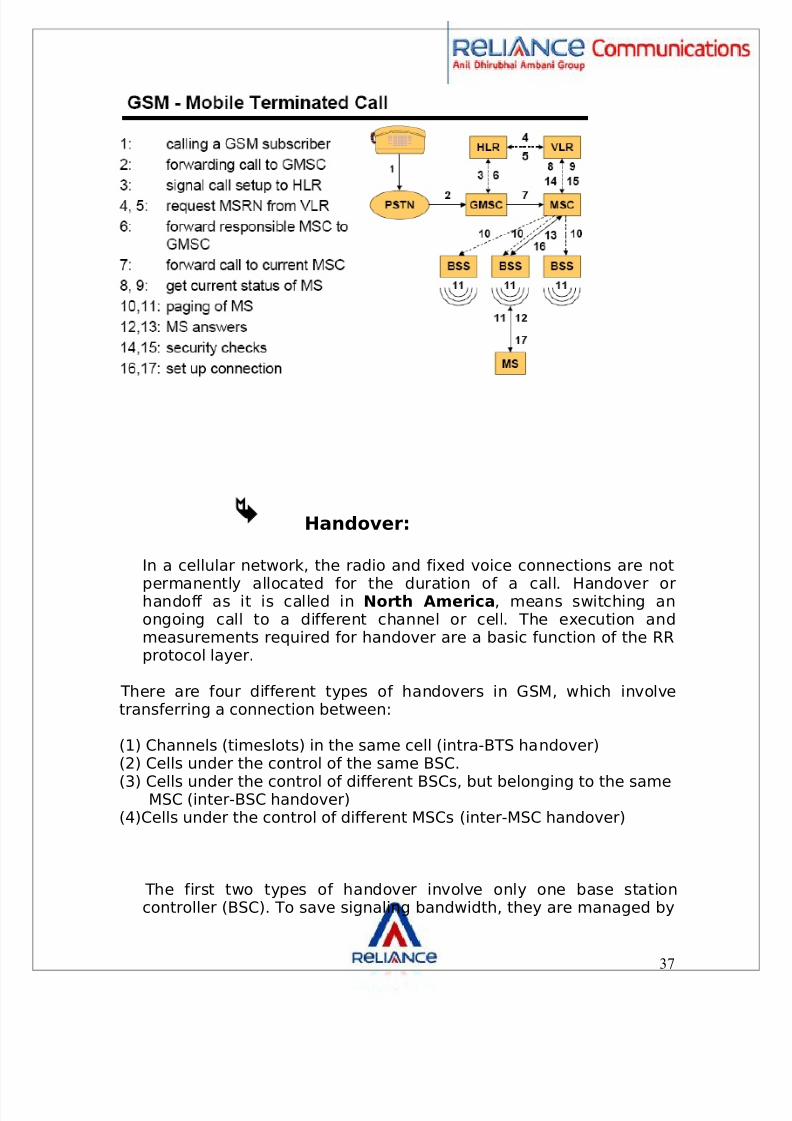
Handover:
In a cellular network, the radio and fixed voice connections are not
permanently allocated for the duration of a call. Handover orhandoff as it is called in North America , means switching anongoing call to a different channel or cell. The execution andmeasurements required for handover are a basic function of the RRprotocol layer.
There are four different types of handovers in GSM, which involvetransferring a connection between:
(1) Channels (timeslots) in the same cell (intra-BTS handover)(2) Cells under the control of the same BSC.
(3) Cells under the control of different BSCs, but belonging to the sameMSC (inter-BSC handover)(4)Cells under the control of different MSCs (inter-MSC handover)
The first two types of handover involve only one base stationcontroller (BSC). To save signaling bandwidth, they are managed by
37

8/7/2019 The GSM standard-N
http://slidepdf.com/reader/full/the-gsm-standard-n 38/49
the BSC without involving the MSC, except to notify it uponcompletion of the handover.
The last two types of handover are handled by the MSCs involved.An important aspect of GSM is that the original MSC, the anchor
MSC, remains responsible for most call-related functions, with theexception of subsequent inter-BSC handovers under the control of the new MSC, called the relay MSC.
Handovers can be initiated by either the BSC or the MSC (as ameans of traffic load balancing). During its idle timeslots, the mobilescans the broadcast control channel of up to 16 neighboring cells,and forms a list of the six best candidates for possible handover,based on the received signal strength. This information is passed tothe BSC and MSC, at least once per second, and is used by thehandover algorithm.
The decision on when to initiate a handover is a function of thefollowing parameters:
Receive quality,Receive level.
Successful handovers in GSM can take place at propagation speedsof up to 250 km/h.
Transmission Overview
During communication, only 40% time is used for conversation; nouseful information is transmitted during the rest 60% time.
If all the information is transmitted to network, many of the systemresources will be wasted, in addition, the interference willaggravate.
In order to solve this problem, GSM adopts DTX technology to stopsignal transmission when there is no voice signal. Therefore, theinterference level is reduced and the system efficiency is improved.
There are two kinds of transmission modes in GSM: normal modeand discontinuous transmission (DTX) mode.
In normal mode, noise and voice have the same transmissionquality. In DTX mode, the transmission of unuseful messages isprohibited. MS only sends man-made noise signals that aretolerable, which
38

8/7/2019 The GSM standard-N
http://slidepdf.com/reader/full/the-gsm-standard-n 39/49
means this noise will not annoy the listeners nor affect theconversation. This kind of noise is called comfort noise .
In DTX mode, 260-bit code is transmitted in every 480 ms; in
normal mode, 260-bit code is transmitted in every 20 ms.
Whether the downlink DTX is adopted or not is controlled bynetwork operators of the exchange part. This kind of control isbased on BSC.
The control information is transmitted to base band processing partthrough dedicated signaling channel, and then arrives at TC throughthe in band signaling of TRAU frame to indicate whether downlinkDTX is adopted. For some vendors, the downlink DTX can beconfigured on the basis of cell.
To reduce the MS's power consumption and minimize interferenceon the air interface, user signal transmission is interrupted duringpauses in speech. “Comfort noise” is artificially generated by theMS to avoid disruption due to an abrupt interruption in speech.
Discontinuous reception (DRX):
Another method used to conserve power at the mobile station isdiscontinuous reception. The paging channel, used by the basestation to signal an incoming call, is structured into sub-channels.
Each mobile station needs to listen only to its own sub-channel. Inthe time between successive paging sub-channels, the mobile cango into sleep mode, when almost no power is used.
Power control:
Power control is to change the transmission power of MS or BTS (orboth) in radio mode within certain area. Power control can reducethe system interference and improve the spectrum utilization andprolong the service time of MS battery. When the Relev and qualityis good, the transmission power of the peer end can be reduced tolower the interference to other calls.
39

8/7/2019 The GSM standard-N
http://slidepdf.com/reader/full/the-gsm-standard-n 40/49
In GSM, power control can be used in uplink and downlinkrespectively. The power control range for uplink MS is 20 dB–30dB .
Based on the power class of MS (most MSs belongs to class 4, whichmeans the maximum transmission power is 33 dbm), each step canchange 2 dB. The downlink power control range is decided byequipment manufacturer. Although whether to adopt uplink ordownlink power control function is decided by network operators, allMSs and BTS equipments must support this function. BSS managesthe power control in the two directions.
Several classes of mobile stations are defined in the GSMspecifications, according to their peak transmitter power. To
minimize co-channel interference and to conserve power, both themobiles and the base transceiver stations operate at the lowestpower level that will maintain an acceptable signal quality. Powerlevels can be stepped up or down in steps of 2 dBm from the peakpower for the class down to a minimum of 13 dBm (20 mill watts forMS).
The mobile station and BTS continually measure the signal strengthor signal quality (based on the bit error ratio), and pass theinformation to the base station controller, which ultimately decidesif and when the power level should be changed.
40

8/7/2019 The GSM standard-N
http://slidepdf.com/reader/full/the-gsm-standard-n 41/49
7. System features This section provides a brief description of the GSM networkfeatures.
Roaming:
The roaming feature allows a user to make and receive calls in anyGSM network and to use the same user-specific servicesworldwide1.
This requires a roaming agreement between the individualoperators. With worldwide roaming the MS is accessible under thesame phone number everywhere.
Multipath equalization:
At the 900 MHz range, radio waves bounce off everything buildings,hills, cars, airplanes, etc. Many reflected signals, each with adifferent phase, can reach an antenna (also known as “multipathpropagation”).
Equalization is used to extract the desired signal from the unwantedreflections. It works by finding out how a known transmitted signalis modified by multipath fading, and constructing an inverse filter toextract the rest of the desired signal.
This known signal is the 26-bit training sequence transmitted in themiddle of every time-slot burst.
The actual implementation of the equalizer is not specified in theGSM specifications.
Frequency hopping:
41
8/7/2019 The GSM standard-N
http://slidepdf.com/reader/full/the-gsm-standard-n 42/49
The mobile station has to be frequency-agile, meaning it can movebetween different frequencies in order to transmit and receive data,etc.
A normal handset is able to switch frequencies 217 times per
second.
GSM makes use of this frequency agility to implement slowfrequency hopping, where the mobile and the BTS transmit each
TDMA frame on a different carrier frequency. The frequencyhopping algorithm is broadcast on the broadcast control channel.Since multipath fading is dependent on the carrier frequency, slowfrequency hopping helps alleviate the problem. In addition, co-channel interference is in effect randomized.
The broadcast and common control channels are not subject to
frequency hopping and are always transmitted on the samefrequency.
Short Message Service (SMS)
SMS offers message delivery (similar to “two-way-paging”) that isguaranteed to reach the MS.
If the GSM telephone is not turned on, the message is held for laterdelivery. Each time a message is delivered to an MS; the networkexpects to receive an acknowledgement from this MS that themessage was correctly received. Without a positiveacknowledgement the network will re-send the message or store itfor later delivery.
SMS supports messages up to 160 characters in length that can bedelivered by any GSM network around the world wherever the MS isable to roam.
Call Waiting (CW)
CW is a network-based feature that must also be supported by theGSM telephone (MS). With CW, GSM users with a call in progress willreceive an audible beep to alert them that there is an incoming callfor the MS. The incoming call can be accepted, sent to voice mail orrejected.
42

8/7/2019 The GSM standard-N
http://slidepdf.com/reader/full/the-gsm-standard-n 43/49
If the incoming call is rejected, the caller will receive a busy signal.Once the call is accepted, the original call is put on hold to allow aconnection to the new incoming call.
Call Hold (CH)
CH must be supported by the MS and the network. It allows the MSto “park” an “in progress call”, to make additional calls or to receiveincoming calls.
Call Forwarding (CF)
This is a network-based feature that can be activated by the MS. CFallows calls to be sent to other numbers under conditions defined bythe user. These conditions can be either unconditional or dependenton certain criteria (no answer, busy, not reachable).
Calling Line ID
Calling Line ID must be supported by the GSM network and thetelephone.
The GSM telephone displays the originating telephone number of incoming calls. This feature requires the caller's network to deliverthe calling line ID (telephone no.) to the GSM network.
Mobility Management (MM)
The GSM network keeps track of which mobile telephones arepowered on and active in the network. To provide as efficient calldelivery as possible,
The network keeps track of the last known location of the MS in theVLR and HLR. Radio sites connected to the MSC are divided intogroups called “ location areas ”. When a call is designated for anMS, the network looks for the MS in the last known location area.
Authentication
43
8/7/2019 The GSM standard-N
http://slidepdf.com/reader/full/the-gsm-standard-n 44/49
Authentication normally takes place when the MS is turned on witheach incoming call and outgoing call. A verification that the »Ki«(security code) stored in the AuC matches the »Ki« stored in SIMcard of the MS completes this process. The user must key in a PINcode on the handset in order to activate the hardware before this
automatic procedure can start.
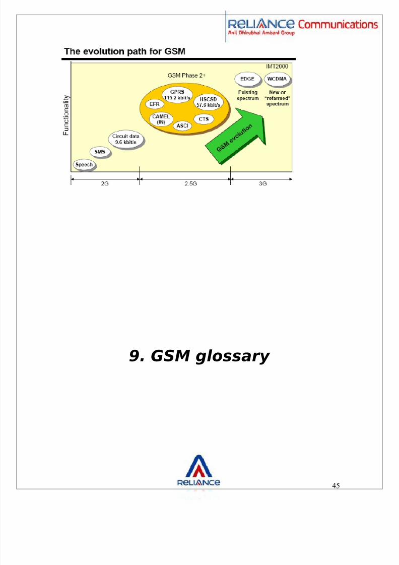
8. The Evolution Path For GSM
44
8/7/2019 The GSM standard-N
http://slidepdf.com/reader/full/the-gsm-standard-n 45/49
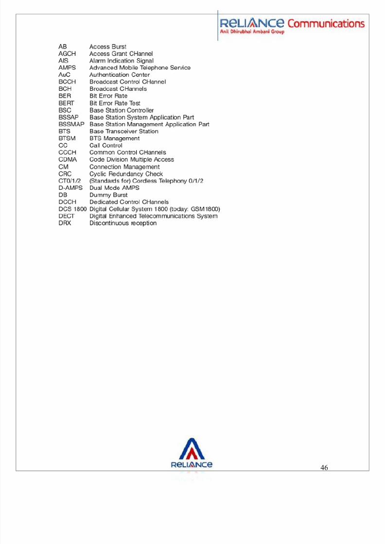
9. GSM glossary
45
8/7/2019 The GSM standard-N
http://slidepdf.com/reader/full/the-gsm-standard-n 46/49
46

8/7/2019 The GSM standard-N
http://slidepdf.com/reader/full/the-gsm-standard-n 47/49
47

8/7/2019 The GSM standard-N
http://slidepdf.com/reader/full/the-gsm-standard-n 48/49
The GSM network consists mainly of the following functionalparts:
MSC
The mobile service switching centre (MSC) is the core switchingentity in the network.
The MSC is connected to the radio access network (RAN); the RAN isformed by the BSCs and BTSs within the Public Land Mobile Network(PLMN).
Users of the GSM network are registered with an MSC; all calls to
and from the user are controlled by the MSC.
A GSM network has one or more MSCs, geographically distributed.
VLR
The visitor location register (VLR) contains subscriber data for
subscribers registered in an MSC. Every MSC contains a VLR.Although MSC and VLR are individually addressable.
GMSC
The gateway MSC (GMSC) is the switching entity that controlsmobile terminating calls.
When a call is established towards a GSM subscriber, a GMSCcontacts the HLR of that subscriber, to obtain the address of theMSC where that subscriber is currently registered. That MSCaddress is used to route the call to that subscriber.
HLR48
8/7/2019 The GSM standard-N
http://slidepdf.com/reader/full/the-gsm-standard-n 49/49
The home location register (HLR) is the database that contains asubscription record for each subscriber of the network.
A GSM subscriber is normally associated with one particular HLR.
The HLR is responsible for the sending of subscription data to theVLR (during registration) or GMSC (during mobile terminating, callhandling).
CN
The core network (CN) consists of, amongst other things, MSC(s),GMSC(s) and HLR(s). These entities are the main components forcall handling and subscriber management. Other main entities inthe CN are the equipment identification register (EIR) andauthentication centre (AUC).
BSS
The base station system (BSS) is composed of one or more basestation controllers (BSC) and one or more base transceiver stations(BTS).
The BTS contains one or more transceivers (TRX).
The TRX is responsible for radio signal transmission and reception.
BTS and BSC are connected through the A bis interface.
The BSS is connected to the MSC through the A interface.
MS The mobile station (MS) is the GSM handset.