The Great Salt Lake West Desert Pumping Project Great Salt Lake West Desert Pumping Project Its...
181
The Great Salt Lake West Desert Pumping Project Its Design, Development, and Operation Utah Division of Water Resources Utah Department of Natural Resources June 1999
Transcript of The Great Salt Lake West Desert Pumping Project Great Salt Lake West Desert Pumping Project Its...

The Great Salt Lake West Desert Pumping Project Its Design, Development, and Operation
Utah Division of Water Resources Utah Department of Natural Resources June 1999

The Great Salt Lake West Desert Pumping ProjectIt’s Design, Development and Operation
Utah Division of Water ResourcesUtah Department of Natural Resources
June 1999

Satellite View of the West Desert Pumping Project
Awarded the 1988 Civil Engineering Achievement of Meritby the American Society of Civil Engineers
The Utah Division of Water Resources, Utah Department of Natural Resources,gratefully acknowledges the contributions and assistance of the following individuals inthe preparation of this report: David W. Eckhoff, Ph.D, P.E., PSOMAS; Karen Nichols,P.E., EWP Engineering; Dee Hansen, P.E., EWP Engineering and former executive directorof the Utah Department of Natural Resources; D. Larry Anderson, P.E., director, UtahDivision of Water Resources; Dennis Strong, P.E., assistant director, Utah Division of WaterResources; Lloyd Austin, P.E. Utah Division of Water Resources; Jim Palmer, P.E., UtahDivision of Water Resources; Robert Seigel, Ph.D, P.E., EWP Engineering; Elaine Boyd, P.E.,EWP Engineering; Ron Ollis, Utah Division of Water Resources.

The Great Salt Lake West Desert Pumping Project
ContentsChapter 1 IntroductionChapter 2 Utah’s Wet Weather Problems 1982-1986Chapter 3 Great Salt Lake BasinChapter 4 Great Salt Lake Contingency PlanChapter 5 Investigation of Great Salt Lake Flood Protection AlternativesChapter 6 Preliminary Design of the West Desert Pumping ProjectChapter 7 Environmental Impact StatementChapter 8 West Desert Pumping Project Permit Agreements and MitigationChapter 9 Final Design of the West Desert Pumping ProjectChapter 10 Construction of the West Desert Pumping ProjectChapter 11 Operating the West Desert Pumping ProjectChapter 12 Shutdown of the West Desert Pumping Project
Technical Appendix AEstimating Evaporation in the West Desert
Technical Appendix BOutlet Canal
Technical Appendix CWind Storm Effects on the Great Salt Lake West Desert Pumping Project
References
FiguresPage
3-2 Great Salt Lake Drainage Basin3-5 Lake Bonneville Area3-6 Historical Great Salt Lake Hydrograph3-7 North and South Arm Elevations of the Great Salt Lake, 1981-19993-8 Gage Locations Used to Determine the Level of the Great Salt Lake, 1875-19835-3 Great Salt Lake Basin with Locations of Water Level Control Alternatives6-3 West Desert Pumping Plan, Preferred Alternative6-11 Ra nge Highline Alternative6-11 Range Boundary Highline Alternative6-12 Lakeside Lowline Alternative6-12 North Railroad Lowline Alternative6-13 South Railroad Lowline Alternative6-13 Wendover Pond Alternative6-14 Bonneville Pond Alternative6-14 Newfoundland Pond Alternative, Counterclockwise Rotation

Contents (continued)
Page
6-15 Newfoundland Pond Alternative, Clockwise Rotation6-15 Boundary Ponds Alternative9-2 Preferred Alternative9-6 West Desert Pumping - Critical Path9-7 West Desert - Critical Path10-2 West Desert Pumping Project, First Phase (Bare Bones) Alternative10-7 Pumping Plant Construction Site at Hogup Ridge Looking West10-8 Pumping Plant Construction Site at Hogup Ridge Looking East10-8 Pumping Plant Excavation10-9 Construction of Base of Pumping Plant10-9 First Engine Being Put In Position10-10 Schematic of Pumps and Engines Placement in Pumping Plant10-10 First Pump Turned On By Gov. Norman H. Bangerter11-3 Elevations of the Great Salt Lake, 1982-198911-4 Cumulative Volumes Pumped and Evaporated11-5 Monthly Pumping Volumes, April - December 198711-6 Monthly Pumping Volumes, January - August 198811-8 Monthly Evaporation in the West Pond, Actual vs. Normal11-9 Average High Temperatures, Actual vs. Normal
Tables3-11 Ranges of Some Dissolved Solids Constituents of Major Tributaries
Entering the Great Salt Lake5-4 Study Title and Primary Investigator5-5 Summary of Great Salt Lake Control/Management Alternatives, 1984-856-5 Alternative Pump Design Criteria and Cost Comparison6-6 Alternative Motor and Drive Design Criteria and Cost Comparison6-7 Comparison of Pumping Plant Capital Costs6-16 Alternative Pond Configuration Alternatives, Characteristics Comparisons6-17 Estimated Costs of Alternative Pond Configurations, South Arm
Operating Elevation 42056-18 Estimated Costs of Alternative Pond Configurations, South Arm
Operating Elevation 42089-4 Design Return Periods for Project Dikes

1-1
West Desert Pumping Project facility 10 miles west of Lakeside in Box Elder County
Chapter 1
Introduction
Construction of the West Desert PumpingProject was an unprecedented flood control action onthe Great Salt Lake, the largest body of water in theWestern Hemisphere without an outlet to a sea. Theproject, designed to enhance the lake’s naturalevaporation process was conceived and constructed inrecord time. Construction began on July 7, 1986. Thefirst of the project’s three pumps began operating onApril 10, 1987. The project was fully operating onJune 3, 1987.
Between fall 1982 and June 1987, the level ofthe Great Salt Lake rose over 12 feet, the tail-end of asteady rise of nearly 20 feet between 1963 and 1987. The lake had more than doubled its surface area andincreased its volume three-fold. The lake level reacheda modern-day record 4211.85 feet above mean sealevel in 1986 and 1987, surpassing the historic highof 4211.60 set in June 1873. At the new record level,the lake covered almost 2,400 square miles andcontained over 30 million acre-feet of water. The
Great Salt Lake went on acostly, destructive rampagewith its horded inflowfrom record amounts ofsnow and rain in northernUtah. Shoreline floodingcaused an estimated $240million in damages toInterstate Highway 80,mineral industries, railwaysystems, sewage treatmentplants, wildlife habitat,recreation areas, andpublic and privateproperty.
Weather expertscould predict noimmediate change in theweather, which led to fearsthat Interstate 80 wouldbe lost to flooding,requiring a new, reroutedfreeway. The Southern

1-2
Pacific and Union Pacific railroads considered shuttingdown operations because of flood damage. Fears greathat the Salt Lake International Airport would stopflights because runway drains were starting to fill up. The Great Salt Lake was out of control.
Construction and operation of the West DesertPumping Project was controversial, and it spawnedconsiderable public and political debate about costsand alternatives to pumping lake brine. Concern aboutthe damage caused by the Great Salt Lake waswidespread, but many people harbored hope the lakewould heal itself. The project, however, eventually wonapproval from the Utah State Legislature by asubstantial margin as the most cost-effective andtechnically sound solution with the greatest publicbenefit. Project engineers faced and overcame uniquechallenges, including the harsh environment of theGreat Salt Lake, remoteness of the Pumping Plant, anddifficult access to construction areas. The project wasnominated for the prestigious Outstanding CivilEngineering Achievement Award from the AmericanSociety of Civil Engineers and won the society’s CivilEngineering Achievement of Merit Award.
A total of $71.1 million was authorized to floodcontrol efforts during a special session of the 1986Utah State Legislature, including $60 million to theUtah Division of Water Resources, Utah Departmentof Natural Resources, to implement the project topump water from the Great Salt Lake into the desertarea west of the lake.
The pumping project was shut down on June 30,1989, after more than two years of successfuloperation. The project pumped about 2.73 millionacre-feet of brines from the lake. The shutdownprocess took about eight weeks, requiring the PumpingPlant to be secured and dismantling, preserving andstoring tools and system control devices.
Since the project was shut down, the PumpingPlant has been inspected periodically and maintainedas insurance against future flooding around the GreatSalt Lake. It is a permanent facility that cannont bedismantled for others uses.
This historical review traces the development,design, implementation, operation and eventualshutdown of the West Desert Pumping Project by thestate of Utah to combat the costly flooding of theGreat Salt Lake, and recounts events and criticaldecisions that led to the project’s construction andoperation.
Valuable information about instrumentation,climate, evaporation and wind tides concerning theGreat Salt Lake has been gained from operating thepumping project and is presented in the appendices ofthis review. -

2-1
Chapter 2
Utah's Wet Weather
Problems 1982-1986
“A Heck of a Way to Run a Desert” 1 Hints of Flooding Problems 1 Memorial Day Meltdown 2
Wildlife in Trouble 2 The Great Salt Lake 3
The Lake Catches It All 4 The State Reacts 5
“A Heck of a Way to Run a Desert” Governor Scott M. Matheson
September 1982 was very wet. A 100-yearstorm on September 26, 1982, unloaded 2.27 inchesof rain at the Salt Lake International Airport.Reportedly, it was the most precipitation evermeasured in one day during 108 years of weatherrecord-keeping in Salt Lake City. Precipitationtotaled 7.04 inches that September, making it thewettest on record in Utah. Total precipitation at theSalt Lake City International Airport during the 1982water year was 22.86 inches, compared to an annualaverage of 15.63 inches.
Snowfall between autumn 1982 and May 1983in north and central mountain areas of the state waswell above average. Alta, about 20 miles southeast ofSalt Lake City at the top of Little CottonwoodCanyon, reported a total 845 inches of snowfall. Thesnow cover on June 1, 1983, ranged from 2.4 to 3.4times greater than average in the Bear River Basin,about 4.2 to 5.2 times greater in the Weber RiverBasin and about 3.7 to 5.2 times greater in theJordan-Provo River Basin. Soil moisture in drainagebasins was considerably more than average. Skierdays and ski industry revenues jumped to newrecords. The elevation of the Great Salt Lake in June1983 was 4200.70 feet above sea level.
Hints of Flooding ProblemsThe Thistle landslide on April 12, 1983, was
the first clue that the high precipitation would causeproblems in the state. The slow-moving landslide inSpanish Fork Canyon in Utah County severed theDenver and Rio Grande Railroad line betweenDenver and Salt Lake City, breached U.S. Highway50 and 6, and dammed off the Spanish Fork River.The backed-up river subsequently inundated thesmall town of Thistle. Eventually the slide became adam 200 feet high that held back an estimated65,000 acre-feet of water. Gov. Scott M. Mathesondeclared the landslide a disaster and asked for $7.8million in federal disaster aid.
Snowpack in the mountains normally peaks bythe first of April, but the weather stayed cold andrain and snow continued until the middle of 1983. A

2-2
State Street flooding in Salt Lake City on May 30, 1983
landslide occurred in Payson Canyon, Utah County,on April 19. The Great Salt Lake rose nearly fourfeet, prompting state officials to consider closing theroad to Antelope Island State Park. A landslideclosed the road through Emigration Canyon east ofSalt Lake City, and city officials " . . . were keepingtheir fingers crossed on City Creek in the canyonbehind the State Capitol Building.”
An emergency drawdown of water in MountainDell Reservoir east of Salt Lake City in Parley'sCanyon was ordered to make room for the expectedheavy runoff from melting snow. Other slidesoccurred in the Canyon Cove area near the HolladayGun Club on the eastern edge of the Salt LakeValley.
Waves on the Great Salt Lake, tossed by 60mile-per-hour winds, battered the Southern Pacificand Union Pacific railroad lines. By May 14, 1983,Utah Lake in Utah County was three feet aboveflood stage and more than 10,000 acres of farmlandwere under water. Talk began about the return ofancient Lake Bonneville to the Great Basin.
Memorial Day MeltdownThe major snowmelt in 1983 started during a
heat wave on the Memorial Day weekend. Runoffgouged down canyon stream beds, especially in City
Creek Canyon, into downtown Salt Lake City. Thecity's State Street eventually became a river bankedby sandbags placed by thousands of volunteers. OnMay 31, a 30-foot high mud slide oozed down RuddCreek into Farmington, Davis County, burying fourhomes and forcing people to evacuate several blocks.That same day, 1,100 people fled a landslide inFairview, Sanpete County. A flood from ChickenCreek washed out I-15 near Levan, Juab County.Someone caught a trout on May 31 in the river thatwas State Street in downtown Salt Lake City.
Runoff into the Sevier River flowed more than500 percent of normal by June 1. A flood of mudcascaded down Stone Creek in Bountiful, DavisCounty, destroying six homes and damaging 50others. Another 1,100 people were evacuated. Bythen, half the state was on emergency disaster status.Then the spillway of the DMAD Reservoir, aregulating reservoir near the end of the Sevier Riverin Millard County, failed on June 23, 1983, andreleased approximately 14,000 acre-feet of water,flooding the farming community of Deseret andcutting off irrigation water supplies to over 60,000acres of farmland.
Bridges that had been erected to funnel footand vehicle traffic across the State Street river inSalt Lake City were being taken down by the end of
June, but spillways of dams along theColorado River were being opened inanticipation of heavy runoff.
Wildlife in TroubleUtah's big game herds foundered in the
heavy mountain snowpack that hadaccumulated by December 1983. Deer andelk abandoned their snowbound brouseareas and browsed in man's domain.Thousands of deer and elk moved ontofarmland and into residential areas andcommunity streets looking for food.

2-3
Utah’s big game herds were fed during the ‘83-’84 winter
Prodded by nationwide public sympathy, andabout $314,000 in donations from across theU.S., the Utah Division of WildlifeResources, other public and private agencies,wildlife interest groups, and volunteersstarted feeding specially formulated foodpellets to deer and hay to elk. The statelegislature also authorized $172,000 to thebig game feeding program. An estimated40,000 to 50,000 deer and 4,000 elk werefed at hundreds of feeding stations. Big gamelosses were dramatically reduced through thefeeding program that continued throughApril 30, 1984.
The Great Salt LakeThe Great Salt Lake in northwestern
Utah is North America's unique inland sea.The lake's terminal desert setting, Pleistoceneheritage, and the nearly five billion tons of salt andother minerals it contains suggest a dead sea. TheGreat Salt Lake is old, but it is not dead.
The saline lake brims with diverse life. Algae,brine flies, brine shrimp and their billions of brightred eggs, salt marsh bushes and grasses, and millionsof shorebirds and waterfowl are part of its life. Ofthe lake's eight named islands, Antelope Island andFremont Island are inhabitable. Antelope Island hasa state park and transplanted buffalo, deer, elk andantelope. Smaller, more inaccessible islands arenesting grounds for migratory birds. The lake hashunting, sailing, mineral industries, micro burststorms and, of course, exquisite sunsets.
The surface level and volume of the Great SaltLake change continuously, primarily in response toclimatic factors. Man's activities have had a lesser,but still important, effect on the level and volume ofthe lake. The lake level generally declines in thespring and summer when the weather is hot enoughthat the loss of water by evaporation from the lakesurface is greater than the inflow from surfacestreams, groundwater and precipitation directly onthe lake. The lake level rises in the autumn when thetemperature cools and the inflow exceeds the loss ofwater by evaporation.
Because the Great Salt Lake is a closed basinand its only outflow is evaporation from its surface,the change in the lake's surface area, volume andlevel reflects the integrated effect of all processes ofthe hydrologic cycle within the drainage basin. Historically, these effects have been displayed bychanges to the inflow to the lake which has causedwide fluctuations in the surface area, volume andstage of the lake. Since 1847, when the historicalrecord of lake level fluctuations began, the annualinflow to the lake has ranged from 1.1 to 9.1 millionacre-feet. The stage reached its first modern periodhigh of 4211.5 feet in 1873 and a low of 4,191.35feet in 1963.
The major surface flows that enter the GreatSalt Lake are from the Bear, Weber and Jordanrivers, the headwaters of which occur within 50miles of each other. Smaller streams that dischargeinto the Great Salt Lake are Farmington, Centerville,Holmes, Ricks, Parrish, Stone and Mill creeks.
The Bear River drains a 6,800 square-mile areain Utah, Wyoming and Idaho and provides thelargest surface inflow to the Great Salt Lake. Someof the heaviest precipitation in the state of Utahoccurs in the Weber River Basin, which covers about2,060 square miles. Flows entering the Great SaltLake from the Jordan River originate in the Uinta

2-4
Southern Pacific Railroad causeway near Lakeside afterJune 7, 1986, storm.
Mountains east of Salt Lake City. The maintributaries above Utah Lake are the Provo andSpanish Fork rivers that rise at 11,000 and 9,500foot elevations respectively. The Jordan River beginsat the outflow from Utah Lake and flows northwardthrough Salt Lake County to the lake. Severalstreams from the west slopes of the WasatchMountains enter the Jordan River along its path tothe Great Salt Lake. The major streams are LittleCottonwood, Big Cottonwood, Mill, Parley's,Emigration and City creeks.
These runoff swollen rivers and streamsharassed homes, businesses, reservoirs and roadsbetween 1982 and 1986, then dumped theirenormous flows into the Great Salt Lake.
The Lake Catches It AllFrom 1963 through 1986, the Great Salt Lake
rose nearly 20 feet, more than doubled its surfacearea, and increased its volume nearly three-fold.Almost 12 feet of the rise occurred since thebeginning of 1982, attributed to excessiveprecipitation in northern Utah drainage areas thatfeed the Great Salt Lake. Inflow to the lake in 1986was more than double the normal average. On June5, 1986, the level of the south arm of the Great SaltLake reached a new record historic high elevation of4211.85 feet above sea level. The lake reached thesame level again in 1987. At this modern recordlevel, the lake covered approximately 2,400 squaremiles and contained more than 30 million acre-feetof water. For perspective, its expanse was only about487 square miles less than the states of Delawareand Rhode Island combined, and the lake containedan acre-foot of water for every resident of Utah,Idaho, Wyoming, Montana, Colorado, NorthDakota, South Dakota, Nebraska, Iowa, Kansas,Oklahoma, New Mexico, Arizona, Nevada, Oregonand Washington.
In its bloated size from the horded inflow fromrecord amounts of snow and rain in northern Utah,the lake went on a destructive rampage. By 1986flood damage estimates around the lake to publicand private land, industries, major transportationroutes, public facilities and wildlife habitat totaledmore than $240 million. Potential cost of damages
was estimated at $1 billion, figuring affectedcompany payrolls, tax payments, capitalexpenditures and purchases.
Flooding problems existed all around the lake.On the south shore, Interstate 80, the Union PacificRailroad, the Great Salt Lake State Park andMarina, and beaches were inundated. Water washingover the freeway during one May 1986 storm backedtraffic for miles. The Union Pacific Railroad thatparallels Interstate 80 along an 11.5 mile stretch onthe lake's south shore acts as a breakwater for I-80.The railroad raised its tracks a number of timesbetween Kennecott and Burmester in TooeleCounty, starting in 1983, that railroad officialsestimated cost about $24 million. The state parkfacilities access roads and marina were washed away;a remnant restroom building withstood the heavywaves the longest, but it too was pulled apart andspread along the shoreline. The Saltair resort andadjoining amusement park that had been reopenedin the spring of 1983 after being restored by severalSalt Lake City businessmen was engulfed; its dancefloor and parking lot ended up under four feet of

2-5
water. Beaches popular with local residents and out-of-state visitors were scoured away by the lake's highwaves.
AMAX Magnesium Corp., one of 11 mineralindustries around the lake, lost a 200-yard section ofa 13-mile-long outer dike to pounding waves. In twodays, nearly 500,000 acre-feet of lake water flowedthrough the breach to inundate the company'smineral extraction ponds. The company employed750 people and indirectly affected 1,150 jobs. Thecompany paid about $1 million in taxes each year.The dike breach stopped a $5 million joint venturewith Diamond Crystal Salt Co. to produce solar saltin ponds planned for the area that was flooded.
The lake level threatened health problems togroundwater in low-lying areas. In Erda, TooeleCounty, 40 septic tanks failed and 300 more wereendangered. In some low-lying areas such as RosePark on the east side of the lake, as many as 1,000homes were threatened. The elevation of Rose Parkwas actually three feet below the level of the lake.
Serious concern was shown for groundwaterproblems that could affect the Salt LakeInternational Airport. The airport is at elevation4213, while the runways are at 4220.
The state and federal waterfowl managementareas were devastated by the lake's intruding saltwater. Facilities at Farmington Bay, HowardSlough, Ogden Bay state waterfowl managementareas and the historic federal Bear River MigratoryBird Refuge were completely destroyed along withfacilities of many private duck and goose clubs.Power and communication towers along the eastshore of the lake were hundreds of yards offshore.Eventually the state park facilities on AntelopeIsland shorelines were washed away, and thecauseway from the Syracuse area to the island wascovered by nearly six feet of water. Productivefarmland in this area was submerged.
Fresh water management areas at LocomotiveSprings National Waterfowl Management Area 50miles west of Brigham City were topped by wind-driven lake water, damaging about 85 percent of the4,000-acre management area. It had been a primefall duck and goose hunting area since 1935. Luckily, the fresh water springs were undamaged.
Several sewage treatment plants became islandsin the lake, protected by walls of sandbags. A radiostation, setting several feet below the shoreline waterlevel, surrounded itself with dikes.
Great Salt Lake Minerals and Chemicals Corp.,a company that operates a huge system of ponds atthe lake's north edge to extract potassium sulfate,potash and salt, diverted employees from mineralproduction to dike building to shore up against theinexorably creeping lake level.
The floods of 1983 were probably the mostwidespread the state has ever experienced. By theend of 1983, flood damage throughout the stateexceeded $478 million, according to the UtahDepartment of Public Safety. Total damage in 1984was estimated at $190 million. Of Utah's 29counties, 22 were approved by the FederalEmergency Management Administration (FEMA) asdisaster areas.
Despite the devastation, the situation spawnedsome humor. Proponents of a so-called "Think LakeBonneville Society" announced rain dances to prodMother Nature to bring back prehistoric LakeBonneville that once covered most of northern Utahand parts of Idaho and Nevada. The society jokinglyclaimed the new Lake Bonneville would boosttourism, create a building boom (people would haveto move to the mountains) and allow planting offresh-water sturgeon to make Utah caviar. Andinterestingly, Utah County commissioners, asking fora day of prayer to stop the flooding, ignited a protestfrom the "Freedom From Religion Foundation" inMadison, Wisconsin, In a letter to Utah AttorneyGeneral David L. Wilkinson, the group called thecommissioner’s plea an "unacceptable abuse ofseparation of church and state."
The State ReactsBefore 1983 the state left most of the
responsibility for flood control with the counties.The 1983 spring floods, however, were so extensiveand serious that the state became deeply involved inflood mitigation and prevention.
Historians say Brigham Young, leader of theMormon pioneers who arrived in the Salt LakeValley in 1847, explored the possibility of spilling
2-6
the lake into the west desert area when the lakepeaked at 4211.5 feet in 1873. But the lakereceded on its own after 1873. During the early1970s, several researchers and state and federalagencies defined the hydrology of the lake,developed computer models of it, and investigatedalternatives for dealing with high lake levels. Summaries of much of this work were published in1973 and 1974 by the Utah Division of WaterResources titled Great Salt Lake Climate and HydrologicSystem and Hydrologic System Management AlternativesReport. The 1977 and 1978 drought years slowedinterest in preparing for problems with high levels ofthe Great Salt Lake. But a flurry of legislation waspassed in 1983 and 1984 legislative sessions whichcommitted the state to help alleviate flood damage.With the continual rise of the lake during thoseyears, a breach of the Southern Pacific Causewaygained support. The elevation of the lake was overthree feet higher on the south side of the causewaythan on the north side. The causeway had become adam. Great Salt Lake Minerals provided $200,000for the state to conduct a feasibility study of theproposed breach. The state's technical position wasthat the breach would lower the level of the south arm of the lake nearly a foot and would be costeffective. In January 1984, after being defeated intwo legislative sessions, the breach of the SouthernPacific Causeway was funded. Costing about $3million, a 300-foot wide bridge was constructed inthe causeway near the west side of the lake and thecauseway was opened on Aug. 1, 1984.
During a two-day special session of the UtahState Legislature that ended on May 14, 1986, a$71.7 million flood control plan was approved topump water and build more emergency shore diking.The pumping project, originally proposed during theadministration of Gov. Scott M. Matheson, was oneof several proposals that were spawned by floodingof the Great Salt Lake. The "last resort" pumpingplan, sponsored by Republican Sen. Fred Finlinson,passed with two-thirds support and was expected tolower the lake by about 16 inches after a year ofpumping. Engineers hoped pumping would start inFebruary 1987.
The flood control bill, HB 6, cautiously backedby Gov. Norman H. Bangerter, provided $60 millionto the Utah Division of Water Resources, UtahDepartment of Natural Resources for pumping thelake water and $10 million to the Disaster ReliefBoard to implement finger diking in Salt LakeCounty, raising breakwaters around the Great SaltLake Marina, raising dikes at the AMAX MagnesiumPlant and American Salt Co. to protect Interstate 80,and further dike protection of sewage treatmentfacilities on the lake's east shore. Tagged to the billwas $1.2 million for engineering design of aninterisland diking proposal and $500,000 forpreconstruction design studies for upstream storagedams, principally on the Bear River, which wouldrequire 10 to 20 years to complete. Flood controlfunding included $30 million from an existing floodmitigation fund deposited in the Conservation andDevelopment Fund managed by the Utah Board ofWater Resources, and $41.7 million obtained from ageneral obligation bond. The bond was to paid offwith a one-eighth cent share of the state's sales taxretained through 1989. -
3-1
Chapter 3
Great Salt Lake Basin
General Aspects 1 Historical Aspects 1
Ancient Lake Bonneville 3 Conditions Of The Great Salt Lake 4
Hydrologic Model For The Lake 8 Drainage and Import-Export
For The Great Salt Lake Basin 9 Bear River 9
Weber River 9 Jordan River 9
Dissolved Solids Inflow To The Lake 10 Climatological Differences 10
General AspectsThe Great Salt Lake is the drainage sink for an
area approximately 22,000 square miles. Most of itsinflows originate in mountainous areas near the lake.The major river systems that sustain the lake derivemostly from the Wasatch Mountains (See Figure 1).
Extremely low precipitation over many parts ofthe Great Basin, particularly that part occupied bythe Great Salt Lake, in conjunction with the largeamounts of precipitation experienced in the highermountain elevations of the watershed give rise to thehydrologic characteristics of the lake and itsenvirons. Typically, the annual precipitation over thelake is less that 12 inches. Snow accumulations inthe adjacent Wasatch Mountains often exceed 200inches in early spring and 40 inches of totalprecipitation in a year. The following information ishelpful to understand conditions in the Great SaltLake Basin that led to the design, development andoperation of the West Desert Pumping Project.
Historical AspectsSignificant exposures of formations from every
geological period exist within a 25-mile radius of SaltLake City. This fact underlies the fundamentalreason for the presence of the Great Salt Lake.
Major geotechnic events of the past 10 to 20million years have created the bowl now occupied inpart by the lake and have exposed ancient andextremely resistant materials as stingy sources ofsediment to the lake. The eastern perimeter of theGreat Salt Lake consists of the Wasatch Front, arange of block-faulted mountains which representthe eastern edge of the basin and range province.The stretching of the earth’s crust in this zoneresulted in a characteristic signature of north-southtrending block-fault mountains interspersed withsediment laden basins. Although the predominantstructures are tilt faults, in the vicinity of the GreatSalt Lake the majority of features are horsts andgrabens. Great Salt Lake occupies a graben complex.
The Wasatch Range that confines the lake onthe east is a straight, narrow horst of resistantPrecambrian rocks (Stockes 1980). Parallel to thishorst is the Wasatch structural trough which is filledby tertiary and quaternary sediments. The trough is

3-2

3-3
complex, consisting of a number of subsidiary blocks.Sedimentation has not kept pace with subsidence,and the situation is nearly a mirror image of theeastern face of the Sierra Nevada Mountains on thewest side of the basin and range province.
The next westerly uplift feature is the Antelope-Promontory Horst, which includes Antelope Islandand the Promontory Peninsula. The later ishistorically significant for the meeting of thetranscontinental railroads in the last century. Westof this chain lies the main body of the Great SaltLake, occupying a complex designated the Great SaltLake Graben. Boundary mountains west of the lakeare the Lakeside Range on the southwest and theTerrace-Hogup ranges on the northwest. HogupCave has yielded some of the oldest relics of humanhabitation in the Great Basin. The lake bed areabetween Lakeside and Hogup ranges has been calledthe “threshold” through which the Great Salt Lakewould flow into the West Desert. Recent studieshave shown the actual threshold extends in asoutherly direction from the Newfoundland Rangeacross the lake bed area at an elevation ofapproximately 4,215 feet above sea level.
West of the Wasatch Range and south of theGreat Salt Lake lies the Oquirrh Range, famous forthe largest open pit copper mine in the world. Thepredominant formation is the Oquirrh Group,consisting of about 11,000 feet of Middle Paleozoiclimestones and related calcareous rocks.
To the northwest of Great Salt Lake, theLakeside Mountains stretch for about 30 miles.Although this range is less impressive than theOquirrh or Wasatch ranges, a Paleozoic sectionmore than 43,000 feet thick has been identified inthese mountains.
The Promontory Range is the remainingsignificant mountain in close proximity to the GreatSalt Lake. It protrudes into the lake for about 30miles, separating Bear River Bay from the so-called“north arm” which was virtually hydraulicallyisolated from the rest of the lake by construction ofthe Southern Pacific Railroad Causeway. ThePromontory Range displays more than 33,000 feet ofsedimentary rocks of Precambrian and Paleozoic
origin. The area occupied by the Great Salt Lake hasbeen sediment starved. Sediments transported to thelake by three major tributaries, the Bear, Weber andJordan rivers, are extremely small size. The riversarrive at the Great Salt Lake at very low gradientsafter traversing some extremely efficient sedimenttraps. This factor, as much as any other, accounts forthe Great Salt Lake being where it is. Stokes (Stokes1980) summarized the situation as follows:
“The fact that this area of faulted crystallinerock appears to have been the center of a longsuccession of Cenozoic water bodies, including LakeBonneville and the Great Salt Lake, suggests thatbedrock types, erosion products, and sedimentationhave been fairly constant for several million years,perhaps ever since the Miocene. Although depressedareas are being filled by deposition, the Great SaltLake Graben, because of the nature of the bedrock insurrounding uplifts (and because of the sparse andfine-grained nature of the sediments in the tributarystream), has always lagged behind so as to be the lowspot of the drainage system.”
Ancient Lake BonnevilleThe shorelines of Lake Bonneville, the
immediate predecessor to the Great Salt Lake, areconspicuous topographical features of northernUtah. They exist at elevations which are now nearly1,000 feet above the surface of the Great Salt Lake,and they attest to substantial changes in theclimatological and hydrological regimes of thePleistocene. The more visable shorelines werehighlighted in National Geographic Magazine (Gore1985). These manifestations of Lake Bonneville arerelatively young, having been established within thelast 25,000 years. Strong indications exist that therewere many marked rises and declines of the lake inthe last 70,000 to 100,000 years (Morrison 1966).Furthermore, these late Pleistocene oscillations werepreceded by at least two earlier periods when lakelevels were generally high in middle Pleistocene, andthere are indications that earlier lakes existed in thisregion in Tertiary time. The sedimentary records andshoreline information of these earlier predecessorsare either buried beneath younger sediments or havebeen obscured and obliterated by subsequent erosion

3-4
and deposition events. Not much evidence exists onthe nature or extent of pre-Bonneville lakes.
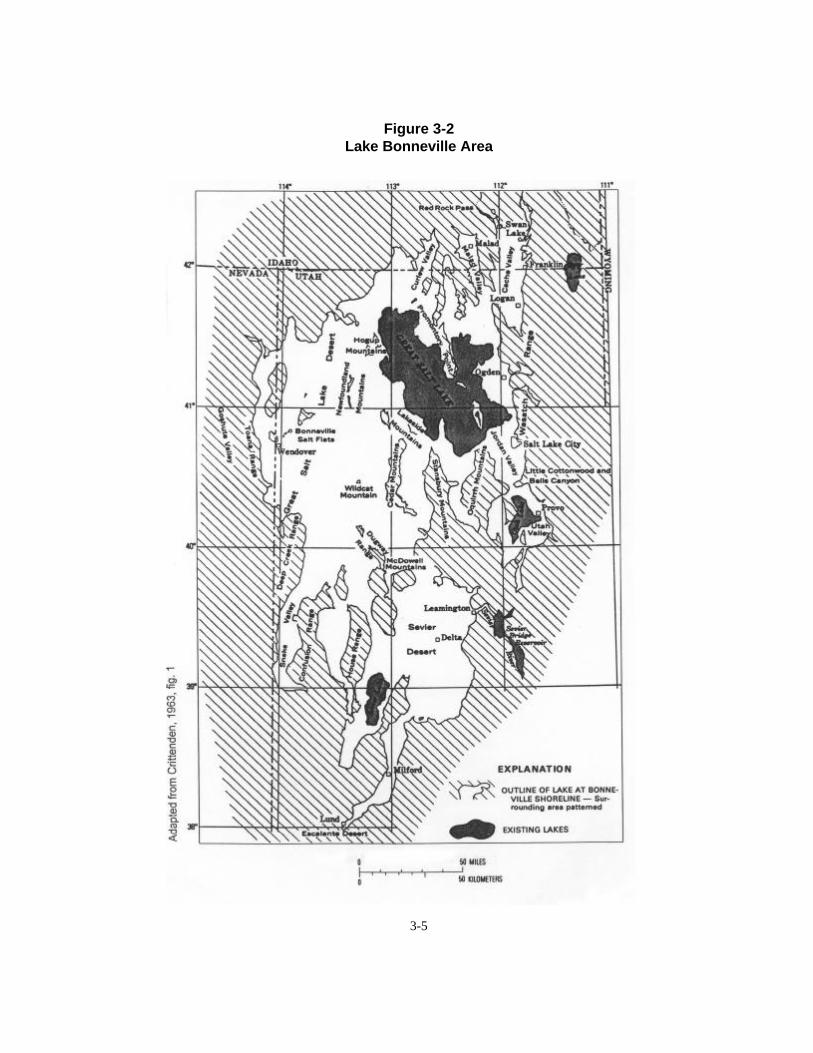
Lake Bonneville was the largest late Pleistocenepluvial lake in the Western Hemisphere. At its peakit inundated an area of nearly 20,000 square miles,as illustrated in Figure 2. It extended nearly 285miles north to south and 140 miles east to west, andseveral times it attained a depth of approximately1,000 feet. It was principally a Utah lake, with partsof it in Nevada and Idaho.
Another factor in the predominance of LakeBonneville is related to a series of ancient volcaniceruptions and lava flows in the Soda Springs area ofIdaho. Evidence shows these lava flows diverted theBear River from its previous course to the SnakeRiver and then to the Columbia River and thePacific Ocean, and redirected it southward into LakeBonneville. Based on today’s conditions, this newtributary to the lake would have increased the totallake surface inflow by about 25 percent.
Conditions of the Great Salt LakeThe surface level and volume of the Great Salt
Lake changes continuously, primarily in response toclimatic factors. Man’s activities have had a lesser,but still important, effect on the level and volume ofthe lake.
The lake has a yearly cycle and a long-rangefluctuation. The yearly cycle begins to decline in thespring and summer when the weather is hot enoughthat the loss of water by evaporation from the lakesurface is greater than the inflow from surfacestreams, groundwater and precipitation directly onthe lake. It begins to rise in the autumn when thetemperature decreases and the loss of water byevaporation is exceeded by the inflow. According torecords, the rise can be expected to begin betweenSeptember and December and the decline to beginany time between March and July.
Because the Great Salt Lake is a closed basinand its only outflow is evaporation from its surface,the change in the lake’s surface area, volume andlevel reflects the integrated effect of all processes ofthe hydrologic cycle within the drainage basin.Historically, these effects have been displayed bywide fluctuations in the inflow to the lake which has
caused wide fluctuations in the surface area, volumeand stage of the lake.
The historical record of lake level fluctuations,shown in Figure 3, began in 1847. The level wasdetermined indirectly by Gilbert (1890) for 1847-75on the basis of reported observations of the depth ofwater over the sandbars between the mainland andAntelope and Stansbury islands. Gilbert relatedthese oral reports to later measurements bydetermining the elevations of Antelope andStansbury islands sandbars, making soundings onthe Antelope Island bar, and relating water levelthere to gage readings near Black Rock andFarmington. The highest level in the modern period(4211.85 feet) was reached in June 1986 andduplicated in June 1987. Level elevations for thenorth and south arms of the lake are shown inFigure 4.
Periodic gage readings after 1875 were made byvarious observers at Black Rock, Farmington,Lakeshore, Garfield, Midlake and Saltair. These gagereadings were summarized in various USGS watersupply reports. Since October 1, 1912, gage heightshave been published in annual water supply papers,and corresponding elevations have been publishedsince 1958. The lake level has been measuredcontinuously at the Salt Lake County Boat Harbor(south arm) since 1939 and at Saline (north arm)since 1966 when the elevation difference betweenthe north and south arms of the lake was firstnoticed. The rapid rise of the lake level in 1984 and1985 prompted relocation of the gage twice near theharbor. Semi-monthly records have been publishedin annual USGS water supply papers and in statereports. The gaging sites and the chronology of therecords are shown in Figure 5.
Research at the University of Utah (Glenne andEckhoff 1976) developed a mathematical model toquantify the relationship between precipitation andthe level of the lake. The research showed anincrease of as little as two inches in the sustainedaverage precipitation at Salt Lake City would resultin a 10-foot rise in the lake level. Events between1982 and 1987 show how accurate that scenariowas. Additionally, Glenne and Eckhoff developed aMarkov model to be used to estimate the statistical
3-5
Figure 3-2Lake Bonneville Area

Fig
ure
3-3
His
tori
cal G
reat
Sal
t L
ake
Hyd
rog
rap
h
3-6

Fig
ure
3-4
No
rth
an
d S
ou
th A
rm E
leva
tio
ns
of
the
Gre
at S
alt
Lak
e, 1
981-
1999
3-7

3-8
Figure 3-5Gage Locations Used to Determine the Level of the Great Salt Lake, 1875-1983
properties (return periods) of high lake levels. Usinga two-year logged precipitation runoff function, theyestimated the lake level would climb above elevation4208 about once in 500 years.
Hydrologic Model For The LakeTo facilitate analysis of the hydrologic system of
the Great Salt Lake with a minimal amount of inputdata, the Utah Division of Water Resources(Stauffer 1985) developed a water balance model ofthe lake based only on annual input data. The modelis able to predict June 1st as well as end-of-the-yearlake elevations either for present water use
conditions, or with projected future additions to ordepletions from the system.
As a result of the lake’s rising levels, theDivision of Water Resources and the Utah WaterResearch Laboratory at Utah State University jointlyupdated the water balance model and developed astage damage model and stochastic generation modelof the lake. The water balance model was modifiedto include the effects of the Southern PacificTransportation Company causeway, usingrecalibrated data for the 1944-83 period. Theupdated model has been used extensively forstudying lake management/control alternatives for

3-9
the lake. A summary of results of this effort waspublished by James, et.al (1984) at the Utah WaterResearch Laboratory.
Drainage and Import-Export for the Great Salt Lake Basin
The Great Salt Lake drainage basin is a closedbasin covering approximately 22,000 square milessurrounding the lake with the lake as the terminalpoint. Because the basin is closed, the only watersupply to the basin is precipitation or imports fromoutside the basin. Outflow from the basin is either evapotranspiration (consumptive use) or exports.Because surface exports from the basin are very smalland imports are less than 100,000 acre-feet annually,virtually all of the precipitation that occurs in thebasin is either consumptively used, evaporated orstored in the basin.
The portion of the precipitation in the GreatSalt Lake Basin that eventually enters the lake assurface flow collects into water courses until thewater enters the lake. The major surface flows thatenter the Great Salt Lake are from the Bear, Weberand Jordan rivers, the headwaters of which occurwithin 50 miles of each other.
Bear RiverThe Bear River rises on the northern slope of
the Uinta Mountains in Utah at about elevation 11,000 feet above sea level. It flows a 500-mile horseshoe-shape course northward through Utah,Wyoming and Idaho, then southward back throughIdaho into Utah and to the Great Salt Lake.Principal tributaries to the Bear River are SmithsFork in Wyoming, the Malad and Cub rivers inIdaho, and the Logan River in Utah.
The Bear River is the largest surface inflow tothe Great Salt Lake. It drains an area of about 6,800square miles in Utah, Wyoming and Idaho. It is avital supply of agricultural water in the Bear RiverBasin and its flows are regulated by several dams anddiversions.
The nearest gaged station to the Great Salt Lakeon the Bear River is near Corrine, Utah, located justnorth of the Bear River Refuge. The flow at Corinne
is considered the contribution of flow in the BearRiver to the Great Salt Lake. Flow records have beenkept at Corinne since 1949 (with a period from1957-63 missing). The missing flow data wereestimated by direct correlation based on a gagingstation 18 miles upstream from Corinne atCollinston, Utah.
Weber RiverThe headwaters of the Weber River begin in the
Wasatch Mountains just south of the headwaters ofthe Bear River at the 10,500 foot elevation. Theriver flows in a northwest direction toward the GreatSalt Lake. Some of the heaviest precipitation in thestate of Utah occurs in the Weber River Basin. Thedrainage area of the entire basin is about 2,060square miles. The natural flow varies markedly fromyear to year due to wide fluctuations inprecipitation. The Ogden River is the major tributaryto the Weber River in addition to many creeks whichadd to the flow. The flow has been stabilized byreservoirs that are part of the Ogden River, WeberRiver and Weber Basin projects.
A gaging station near Plain City is about sixmiles from the Great Salt Lake. Below this stationthe river branches into three distinct channels withnumerous side channels. Because there is little dataavailable below Plain City, the flow at Plain City isused for the Weber River contribution to the surfaceflow. The historical record for this station is from1904 to the present.
Jordan RiverThe flow entering the Great Salt Lake from the
Jordan River originates in the Uinta Mountains eastof Salt Lake City. The main tributaries above UtahLake are the Provo and Spanish Fork rivers that riseat 11,000 and 9,500 foot elevations respectively.The Jordan River begins at the outflow from UtahLake and flows northward through Salt Lake Countyto the lake. Several streams from the west slopes ofthe Wasatch Mountains enter the Jordan River alongits path to the Great Salt Lake. The basin area is3,490 square miles. Heavy water demands are placedon the Provo-Jordan River Basin system, includingmunicipal and industrial waters for the cities from

3-10
Payson to Bountiful along the Wasatch Front, andconsiderable agriculture in Utah and Salt Lakecounties.
Flow records of the Jordan River are the poorestof the major inflows to the Great Salt Lake. The flowof the Jordan River near the Great Salt Lake was notmeasured until 1965, and the gaging at 2100 SouthStreet in Salt Lake City began in 1943. The flow atthe Jordan Narrows has been monitored since 1913.The major tributaries, Little Cottonwood, BigCottonwood, Mill, Parleys, Emigration and Citycreeks along the Wasatch Front have beenmonitored for the last 50 years. But the diversionpatterns for municipal, industrial and agriculturalpurposes are so complex that correlation between thesum of these flows and the flow at the lake isextremely difficult. For this reason, the combinedflows of the Jordan River and surplus canal at 2100South Street in Salt Lake City are used as the inflowto the Great Salt Lake.
Estimates vary on the amount of ungaged flowthat enters the lake from other sources. Based oncomputer correlations, however, other surface flowentering the lake is approximately 8 percent of thecombined Bear, Weber and Jordan rivers gaged flow(Stauffer 1985).
Dissolved Solids Inflow to the LakeStudies by the USGS have indicated the Bear,
Weber and Jordan rivers systems contributeapproximately 60-80 percent of the surficialdissolved solids load entering the Great Salt Lake.The remaining dissolved solids come from smallstreams and canals. This inflow of dissolved solidsamounts to approximately 2,150,000 tons per year.The water that enters the Great Salt Lake in thethree main streams is quite different in chemicalquality from the water in the headwaters of thesestreams. Most of the runoff in the three streamsoriginates as snowmelt or rainfall on the UintaMountains and Wasatch Mountain Range, and thisrunoff is low in dissolved solids and of the calciumbicarbonate type, suitable for most any use.
In the lower reaches of the Bear and Jordanrivers, however, the dissolved solids increase becauseof evapotranspiration, return flow from irrigated
lands, discharge of industrial and municipal wastes,and groundwater inflow: and the water type changesin these two streams as the major dissolvedconstituents become sodium, chloride and sulfate. Inthe Weber River, however, the dissolved solids donot greatly increase and the water type remains thesame.
Table 1 shows the quality of water entering theGreat Salt Lake from the three major tributariesduring the water year 1975, and illustrates theranges of some of the more common ionconstituents.
Estimates of subsurface inflow volume varyfrom 275,000 acre-feet, reported by Peck andRichardson (1966) as the average for years 1937-61,to an average of 75,000 acre-feet for the years 1937-73, reported by Arnow (1978). Handy and Hahl(1966) reported a dissolved solids load of 1.2 milliontons contained in 200,000 acre-feet of subsurfaceinflow during 1964. This flow for 1964 would havean average concentration of 700 mg/l total dissolvedsolids. The volume of subsurface inflow to the lakeand the dissolved solids load are vary smallcompared to the total volume and load of the lake.
Climate and precipitation patterns over theGreat Salt Lake are complex. Whelan (1973) states:“The climate of the area ranges from temperate-aridwest of the lake, with an annual precipitation of 4.5inches, to temperate semi-arid east of the lake, withan annual precipitation of 16 inches.” Precipitationon the surface of the Great Salt Lake is estimated to contribute 25 to 30 percent of the total inflow to the lake.
Climatological DifferencesThe climate of the Great Salt Lake Basin is
dominated by the Sierra Nevadas some 500 miles tothe west and the Rockies several hundred miles tothe east. The mountain ranges forming the westcoast chain modify the character of winter stormswhich move across the Great Salt Lake Basin. Mostof the moist Pacific air which brings winterprecipitation to the basin must move across thesemountain barriers with consequent moisture loss.This climatic factor accounts for the semi-arid natureof the Great Salt Lake Basin.

3-11
Table 3-1Ranges of Some Dissolved Solids Constituents of Major Tributaries Entering the Great Salt Lake
Water Year 1975 (Values in mg/l)
Tributary SilicaHigh Low
CalciumHigh Low
MagnesiumHigh Low
SodiumHigh Low
PotassiumHigh Low
BicarbonateHigh Low
SulfateHigh Low
ChlorideHigh Low
Bear Riverat Corrine
Weber Riverat Plain City
Jordan Riverat 5800 So.SLC
16 8
12 8
31 20
69 51
65 35
180 83
65 20
23 9
74 54
300 59
49 12
220 140
22 7
7 2
21 13
372 211
303 135
354 251
67 31
34 15
460 240
460 85
64 16
310 190
Data from Water Resources Data For Utah, U.S. Geological Survey Water Data Report UT-75-1, Oct. 1974 - Sept. 1975
The Rocky Mountains to the east of the GreatSalt Lake Basin also have a marked moderatinginfluence on the climate of the basin. The mountainsprevent the westward penetration of all butexceptionally strong outbreaks of cold continentalair. These cold masses which sweep across thecentral states in winter have their source in thesnow-covered plains of northern Canada and the ice-covered wastes of the Arctic.
Topography of the basin influences the climatein another way. Air over the surrounding mountainslopes is cooled during the long winter nights byrelatively colder surfaces of the slopes. This colderair flows down the slopes and canyons and collects atthe bottom of the basin just as the water of old LakeBonneville once did.
The semi-arid continental climate of the SaltLake Basin is characterized by large variations inmean temperatures because of the effects of localtopography. Mean average annual temperaturesrange from 53.2 degrees F. at Antelope Islandlocated in the Great Salt Lake to 44.9 degrees F. atSnowville, Utah, about 20 miles north of the lake.Temperatures along the southern and western shoresof the lake range between 41 and 52 degrees withslightly colder mean temperatures of 49 and 50degrees F.
The warmest temperature recorded at an officialstation in the basin was 112 degrees F. at Wendover,Utah, on July 13, 1939. The second highest, 111
degrees F., was observed at Antelope Island on July25, 1959. The lowest temperature recorded near thelake was -32 degrees F. at Corinne, Utah, onChristmas Day 1924. The record low temperaturewas measured at -44 degrees F. at Lewiston, Utah,in Cache Valley. -


4-1
Chapter 4
Great Salt Lake Contingency Plan
The Department of Natural Resources andEnergy published a report in January 1983 titled,Recommendations for a Great Salt Lake Contingency Planfor Influencing High and Low Levels of the Great SaltLake. The contingency plan was prepared withinparameters of the December 16, 1976, ComprehensivePlan for Managing the Great Salt Lake. Thecontingency plan of the Department of NaturalResources and Energy contained recommendationsto meet the then legislative mandate for maintainingthe level of the lake below 4202 feet of elevation(Utah Code Annotated, 1953, as amended in 1979Title 65-8a-7).
At the time, the news media and others madelight of the law that required the lake to bemaintained below elevation 4202. The contingencyplan, however, focused on the concern from industrythat resulted in recommendations to the governorthat something needed to be done to protectimportant investments and resources near the lake.In retrospect, it is interesting to note that thecontingency plan was not prepared because of theabnormal high precipitation and flooding thatoccurred in September 1982. The plan was preparedbecause the lake since 1963 had been rising at analarming rate and was predicted to reach elevation4202 feet by 1983.
As early as 1976, the Great Salt Lake TechnicalTeam started looking at the rising lake level. Ideaslike pumping lake water into the West Desert,diking, and upstream development were beingdiscussed.
The 1983 contingency plan basically gave abrief history of lake fluctuations and analyzed whatit called the three most likely trends for future lakelevels. They were:
1. Most likely lake level trend: elevation 4207 feet by the year 2025.2. Most likely low lake level trend: elevation 4189 feet by the year 2010.3. Most extreme, yet possible, high lake level trend: elevation 4210 feet by the year 1998.The third trend, elevation 4210 feet by the year
1998, viewed as the most extreme, was actually quiteclose in elevation but not accurate in timing. Thelake reached elevation 4211.85 by June 5, 1986.

4-2
The plan also assembled information aboutalternatives that had been previously studied, suchas pumping water from the lake into the WestDesert, breaching the Southern Pacific RailroadCauseway, diking low areas around the lake, andstoring/developing water upstream to the Great SaltLake before it enters he lake.
The contingency plan was the first report torecommend pumping water into the West Desert asthe best short-term solution to lake flooding. Itfurther suggested that long-term solutions mightinclude development of the Bear River, creation offresh water ponds in the north end of Bear RiverBay, or possible development of a peak powerproject in Puddle Valley.
The plan concluded, “. . . there are presentlyinsufficient data on which to base firm actionrecommendations,” and urged that additionalfeasibility analyses be completed.
This conclusion led to donations from privatecapital to begin a feasibility analysis of pumpingwater from the Great Salt Lake into the WestDesert. -
5-1
Chapter 5
Investigation of Great Salt Lake Flood Protection
Alternatives
Studies and investigations to find alternatives toprotect development around the Great Salt Lake didnot start with the high levels of the 1980s. TheGreat Salt Lake has historically experienced widecyclic fluctuation of its surface elevation, which hascontinually plagued those who have utilized itsshores.
During the period from 1940-1965, when thelake was relatively low, it was thought by many thatthe lake would remain low or even dry up. Development around the lake during this periodincluded large wildlife management areas at themouths of the rivers, large evaporation ponds in lowareas for the salt extraction industries, major roadsand railroads across and along the shores, recreationfacilities, and a causeway connecting the east shoreto Antelope Island.
A peak elevation of 4202.3 feet was reached in1976 that prompted a renewal of public awareness ofthe lake and problems associated with high levels ofthe lake. This public awareness provided newlegislative support to state agencies and universitiesto address problems related to flooding problemsaround the lake.
Industries along the lake’s shore at this timewere experiencing a financial strain due toproductivity losses and structural damage. Concernalso existed for wildlife and recreational areas aroundthe lake. In the three years following 1976, the lakelevel receded more than two feet (1977-78 was oneof the lowest precipitation years on record). InSeptember 1982, however, the lake began risingrapidly again due to abnormal high rainfall and anabrupt ending of the evaporating season. Thecontinued high precipitation caused inflows of 7.5million acre-feet in 1983 and 9.0 million acre-feet in1984. This caused the lake to peak at elevation4204.70 feet in June 1983 and at elevation 4209.25feet in June 1984. The two successive rises of thelake (approximately five feet each) were the twolargest rises of the lake in historical record.
Alternatives were proposed by the Division ofWater Resources and many others were suggested bythe public. Alternatives were grouped as follows:
5-2
1. Export flood flows from the Great SaltLake drainage basin, mainly to the BearRiver and Sevier River drainages.
2. Store water within the basin before itreaches the Great Salt Lake, mainly inreservoirs associated with the Bear River. Most of the reservoirs were part of ongoingstudies on the Bear River to develop someof the Bear River flows.
3. Consume (through evapotranspiration)large amounts of water within the basin. This type of alternative would require largediversions to new agriculture lands. Insome cases, water would be supplied fromone of the reservoirs involving the BearRiver. Only a couple of proposals matchedthis concept; one was the Utah Lake/CedarValley Pumping Project.
4. Continue letting the flood flow collect inthe Great Salt Lake.
Many of the proposed alternatives dealt with flood flows and high lake level once the water was inthe lake. These ideas included:
(a) breach the Southern Pacific RailroadCauseway to lower the south arm andraise the north arm,
(b) dike around the lake to protect majorfacilities and resources, close theSouthern Pacific Causeway and divertthe Bear River into the north arm tomaintain the south arm lower than thenorth arm,
(c) build a pump/storage/power project inPuddle Valley, and
(d) pump water from the lake to the WestDesert (West Desert PumpingProject).
The Division of Water Resources published areport in January 1984 entitled, Great Salt LakeSummary of Technical Investigations for Water LevelControl Alternatives that summarized alternativesassociated with the Bear River, Utah Lake and theGreat Salt Lake, except diking. Alternativesaddressed in the report are shown in Figure 1, and
Table 1 lists alternatives studied and primaryinvestigators.
A major study, Great Salt Lake Diking FeasibilityStudy, was prepared in December 1984. In 1984-85,these ongoing investigations were summarized in theshort report, Great Salt Lake Summary of LakeControl/Management Alternatives.
Table 2, among other things, lists projects,proposals, schemes, etc. as of 1984-85 which wereidentified for possible control/ management of thehigh levels of the Great Salt Lake. It shows the statusof various investigations, shows construction time,identifies the type of control alternatives wouldprovide, gives information about impacts to varioususes, and shows effectiveness of alternatives to lowerthe lake level.
The table also shows which projects/schemescould be constructed on a short-term schedule andthe effect they would have on lowering the level ofthe south arm of the lake. It shows that projects suchas damming the north arm of the lake and pumpingbrine into Puddle Valley had a large potential tolower the lake level, but they were very costly andwould take more than five years to construct. Thetable shows the West Pumping Project as the bestalternative to deal with the existing problems withthe high lake level.
During 1983, and to a limited extent in 1984,the Division of Water Resources under specialassignment from the Executive Director of theDepartment of Natural Resources conductedtechnical studies on several alternatives tosupplement existing data and to assess the feasibilityof the alternatives. The studies, undertaken by thedivision in 1983, were summarized in its reportGreat Salt Lake Summary of Technical InvestigationsWater Level Control Alternatives.
The ongoing work in 1984 relates mainly todirections given to the Division of Water Resourcesthrough Senate Bill 97. Engineering studies beingconducted by the division included water qualitystudies on the Bear River; investigations related tothe South Fork, Avon and Oneida NarrowsReservoirs on the Bear River; the Cedar ValleyProject; work on the West Desert Pumping

5-3
Figure 5-1Great Salt Lake Basin with Locations of Water Level Control Alternatives

5-4
Table 1Study Title and Primary Investigator (1983)
Study Investigator
Bear River Basin
Mill Creek Reservoir PRC Engineering, Inc.
Amalga Reservoir Dames and Moore
Honeyville Reservoir Palmer-Wilding Consulting Engineers
Washakie Reservoir Horrocks-Carollo Engineering
East Promontory/West Bay PRC Engineering, Inc.
Lampo Reservoir Palmer-Wilding Consulting Engineers
Oneida Narrows Reservoir Division of Water Resources
Cutler Reservoir Enlargement Division of Water Resourcesa
Soda Springs Reservoir Idaho Water Resources Boardb
Diversion to Portneuf River Higginson-Barnett Consultants
Hansel Valley Storage Division of Water Resources
Great Salt Lake
West Desert Pumping Alternative Eckhoff, Watson & Preator
Puddle Valley Pumping & Power Generation Utah Water Research Lab. - USU
S.P.R.R. Causeway Breach Division of Water Resourcesc
Evaporation & Precipitation Effects of WDP No. American Weather Consultants
Damages Incurred Due to Rising Lake Level Bureau of Economic and Business Research - U of U
Hydrologic Modeling Utah Water Research Lab. - USU
Utah Lake
Pumping to Maintain Compromise Elevation Division of Water Resources
Pumping for Irrigation Projects Division of Water Resourcesd
aSome information provided by Harza Engineering through courtesy of Utah Power and Light Company.bStudy done in 1981 for state of Idaho by J-U-B Engineers, Inc.cInformation provided by Southern Pacific Transportation Company.dCooperative Studies with Bureau of Reclamation, July 1971-April 1972.

Tab
le 2
Su
mm
ary
of
Gre
at S
alt
Lak
e C
on
tro
l/Man
agem
ent
Alt
ern
ativ
es, 1
984-
85
PRO
JEC
TS/
SCH
EMES
Stat
us o
f Pro
ject
Inve
stig
atio
ns1
Sche
dule
for
Con
stru
ctio
n, E
tc.
Typ
e of
Con
trol
in T
erm
sof
Sto
rage
, Eva
p., E
tc.
Impa
ct t
o V
ario
us U
ses.
Pos
itiv
eor
Neg
ativ
e2St
atus
of C
ost
Info
rmat
ion3
Effe
ct o
n Lo
wer
ing
the
S.A
. Pea
k in
inch
es
Reconnaissance
Feasibility
Final Design
Constructed
Short, 0-2 yrs.
Medium, 2-5 yrs.
Long, 5- yrs.
Export from Basin
Storage above GSL
Storage in/near GSL
Consumptive Use
Evaporation
Lake Level Adjustment
Lake Level Control
Agr., M&I Uses
Recreation
Fishing-Wildlife
Major EIS Prob. Yes-No
S.A. Mineral Ind.
N.A. Mineral Ind.
Status of Data
Capital Costsin Million $
O & M Costs
First Year Operation
Reduction of Peak Levels underConditions 1983
Bea
r R
iver
Bas
inM
ill C
reek
Res
ervo
irC
XX
XS
LL
M?
SS
P16
.6n/
a0.
32.
0A
mal
ga R
eser
voir
CX
XX
ML
LM
?S
SP
59.3
n/a
1.6
6.0
Hon
eyvi
lle R
eser
voir
CX
XX
SL
LM
?S
SP
35.6
n/a
1.1
4.0
Eas
t Pro
mon
tory
/Wes
t Bay
Res
.C
?X
XX
M?
LM
?M
MP
31.5
n/a
3.2
6.0
One
ida
Nar
row
s R
eser
voir
CU
XX
XS
LL
??
SS
R15
.6n/
a1.
33.
0C
utle
r Res
ervo
ir E
nlar
gem
ent
CP
XX
XM
LL
M?
SS
R19
4.8
n/a
2.8
9.0
Soda
Spr
ings
Res
ervo
irC
XX
XS
LL
??
SS
P16
.4n/
a0.
42.
0H
anse
l Val
ley
Stor
age
CX
XX
SL
??
?S
SR
141.
3n/
a7.
03.
0D
iver
sion
to P
ortn
euf R
iver
CP
?X
XM
??
?Y
S S
R9.
1n/
a2.
012
.0A
von
Res
ervo
irU
XX
XS
LL
??
SS
-
n/a
n/a
0.3
2.0
Div
. Bea
r Riv
er W
ater
to S
.L.C
.U
XX
SL
??
?S
S
n/a
n/a
n/a
4.0
Was
haki
e R
eser
voir
CX
XX
SL
LM
?S
SP
75.0
n/a
1.7
5.0
Lam
po R
eser
voir
CX
XX
SL
LM
?S
SP
14.7
n/a
0.2
1.0
Roz
el Ir
rigat
ion
Proj
ect
UX
XS
LO
O?
SS
-
n/a
n/a
n/a
3.0
Uta
h L
ake/
Ced
ar-R
ush
Val
ley
Pro
ject
Pum
ping
to M
aint
ain
Com
prom
ise
CU
?X
XX
SO
?M
?S
SR
70.1
n/a
3.7
Pum
ping
for I
rrig
atio
n Pr
ojec
tC
UX
?X
SL
??
?S
SR
37.6
n/a
0.8
6.0
Gre
at S
alt L
ake
S.P.
R.R
. Cau
sew
ay B
reac
hC
*X
XM
OO
??
LN
C3.
7n/
a10
.010
.0W
est D
eser
t Pum
ping
CP
XX
X?
LO
OO
YL
LF
40.0
4.0
20.0
40.0
Pudd
le V
alle
y St
orag
eC
X?
XX
?L
O?
?Y
LL
R50
.027
.030
.00.
1Pu
ddle
Val
ley
Pum
p St
orag
eC
XX
X?
LO
??
YL
LR
130.
047
.030
.00.
2D
amm
ing
Bea
r Riv
er B
ayU
PX
XX
?S
?L
?Y
LN
-30
.0n/
a12
.00.
1D
amm
ing
Nor
th A
rm G
SLU
XX
??
LO
??
YN
L-
400.
0n/
a60
.045
.0T
otal
Dik
ing
Eas
t Sho
re A
reas
CP
X?
X?
OO
??
YN
NR
200.
0n/
a-0
.0-0
.0Se
lect
ive
Dik
ing
Eas
t Sho
re A
reas
UP
X
X
?O
O?
?Y
NN
R25
.0n/
a-0
.0-0
.0
1 C in
vest
igat
ion
com
plet
e at
that
sta
tus,
U in
vest
igat
ion
unde
rway
at t
hat l
evel
, and
P p
ropo
sed
inve
stig
atio
n at
that
leve
l.2 L
larg
e be
nefit
, M m
ediu
m b
enef
it, S
sm
all b
enef
it, O
no
bene
fit,
N n
egat
ive
bene
fit,
and
? un
know
n be
nefi
t.3 R
reco
nnai
ssan
ce c
ost e
stim
ate,
F fe
asib
ility
leve
l cos
t est
imat
e, D
fina
l des
ign
cost
est
imat
e, C
cos
t as
cons
truc
ted
and
n/a
cost
not
ava
ilabl
e.

5-6
Alternative; and some in-house reconnaissance-levelinvestigations of proposals to dam the north arm ofthe Great Salt Lake, dam the Bear River Bay, andselective diking along the east shore of the lake.
In general, the analysis of these alternatives,together with economic and political aspects, led tothe following considerations.
(1) Export flood flows from the Great SaltLake Drainage Basin - Diversion toPortneuf River was evaluated, but costswere three to four times more than WestDesert pumping with only a third of theeffect on the lake. Many other concernswere raised in any proposal to add floodflows to streams outside the basin whichmay also be at peak flows.
(2) Store water within the basin - Investigations showed that thesealternatives (when analyzed as a Great SaltLake flood alternative) required five-plusyears to construct, would have very smallimpact on the level of the lake, and weremore expensive than West Desertpumping.
(3) Evapotranspiration of new amounts ofwater within the basin - These alternativewere included in the Utah Lake/Cedar-Rush Valley Project. They also weremedium to high time for construction,costly compared to West Desert pumping,and would have very small effect on thelevel of the Great Salt Lake. Further, it wasuncertain if such a project would have awater supply during average water years.
Eventually, the evaluation of alternatives led tothe recommendation that West Desert pumping wasthe alternative that could be constructed in a shortperiod (less than two years), would have a majorimpact on the level of the Great Salt Lake, andwould have the best benefit-to-cost comparison.
Results of these collective investigations led toan overall concept for dealing with the floodingGreat Salt Lake.
(1) Allow/use the natural terminal point of thelake to store flood flows and find ways toremove them once captured in the lake.
(2) Breach the causeway to reduce the headdifference between the north and southarms of the Great Salt Lake. This, in effect,would lower the south arm where much ofthe flood damages occurred.
(3) Build the West Desert Pumping Project toremove water from the lake throughevaporation. The project would evaporateup to 800,000 acre-feet of additional waterfrom the Great Salt Lake.
(4) Build certain dikes to protect infrastructurearound the lake. These included dikesaround major sewage treatment plants. Raise parts of roads around the shore areasof the lake, including areas of I-80 and I-15. Also raise major causeways/dikes withinthe lake, including the railroad causeway. -
References:
Anderson, D. Larry, Great Salt Lake Flooding,paper presented to the Interstate Conference onWater Problems (ICWP) at Big Sky, Montana, UtahDivision of Water Resources, Salt Lake City, Utah, August1985.
Arnow, Ted, Water Level and Water QualityChanges in Great Salt Lake, 1847-1983, Circular 913,U. S. Geological Survey, Salt Lake City, Utah, 1983.
Austin, Lloyd H., Lake Level Predictions of theGreat Salt Lake, paper in Great Salt Lake - A Scientific,Historical and Economic Overview, edited by J. WallaceGwynn, Ph.D., Utah Department of NaturalResources, Division of Geological Survey, Salt LakeCity, Utah, 1980.
Utah Department of Natural Resources,Recommendations for a Great Salt Lake Contingency Plan- For Influencing High and Low Levels of Great Salt Lake,Salt Lake City, Utah, 1983.

6-1
Chapter 6
Preliminary Design of the West Desert
Pumping Project
Introduction 1 West Desert Pumping -
Basis of Design 1 Elements of the Project 2
Comparison of Pumping Plant Alternatives 2
Costs 8 Evaporation Pond Alternatives 8
Geotechnical Considerations 10 Hill Air Force Range 20
Coordination With Southern Pacific Transportation Company 21
Summary and Conclusions 22
IntroductionA Final Report West Desert Pumping Alternative -
Great Salt Lake was prepared in December 1983 forthe Utah Division of Water Resources. This reportdocumented the engineering feasibility studiesconducted for the division to review and evaluate theproposed action plan and other information relatedto the West Desert area.
This chapter summarizes findings from thatreport. In general, the report concluded that theproject was feasible and identified major elements ofthe project. The project consisted of a pumpingplant, system of canals and ponds, containmentdikes and return brine conveyance system.
West Desert Pumping - Basis of DesignThe Great Salt Lake West Desert is in the Basin
and Range province, which is characterized by flatbasins separated by abrupt north-south tendingmountain ranges. The basins were further flattenedby deposition in Lake Bonneville, which covered thisregion. Uniquely, the West Desert basins are nearlythe same elevation as the lake.
As described in the Great Salt Lake ContingencyPlan, the West Desert Pumping Alternative was oneof several alternatives identified to deal withcontrolling or managing high levels of the Great SaltLake. The pumping alternative was the plan to pumpwater from the Great Salt Lake (south arm) into thedesert west of the Great Salt Lake and evaporate it.
This alternative was first investigated by theSacramento District, Corps of Engineers for theGreat Salt Lake Hydrologic Subcommittee in July1976. The report by the Corps of Engineers was laterpublished as Appendix C in the Great Salt LakeHydrologic System Management Alternatives Report bythe Division of Water Resources in May 1977.
The Corps investigated three alternatives thatmight achieve net evaporative losses of 310,000,380,000 and 850,000 acre-feet annually. Computermodel evaluation of these alternatives indicated thatlarger amounts of net evaporation would benecessary for the pumping alternative to have somereasonable ability to “manage" high levels of theGreat Salt Lake. The alternative (with its variousoptions) considered in this investigation was,

6-2
therefore, initially as large as possible. The goal wasto identify a pumping alternative with a netevaporation in excess of 1,000,000 acre-feet per year.
In order to avoid filling the shallow desert basinswith precipitated salt, it would be necessary toconvey concentrated brines back to the lake. Thisstep would also avoid mineral depletion in the lake.A similar salt problem mandated that the south armbrines of the Great Salt Lake be the source forpumping. Because south arm brines are a lighterdensity (less salty) than the north arm brines, theycan be evaporated/concentrated easier and to a largerextent before salt crystals begin to form.
Although the Great Salt Lake is lower inelevation than the area identified for the WestDesert Pond, lift pumping could help transfer largequantities of water from the lake to the pond. Undernatural conditions, about 300,000 acre-free of watercould be contained in the West Desert withoutflooding facilities in the Bonneville Basin east ofWendover, or without flow returning to the GreatSalt Lake. Using dikes and levees could substantiallyincrease the storage volume of the system.
An ideal arrangement would be to construct oneretention dike near the west edge of the lake. Thiswould minimize construction and pumping costs.However, the Hill Air Force Range uses largeportions of the desert for weapons testing, and thesefacilities must be protected and maintained. Railroadtracks and embankments must be likewise protectedfrom flooding and wave action. Similar protectionmust be provided for I-80.
Elements of the ProjectMajor elements of the system, Figure 6-1, are:A. A breach of the Southern Pacific
Transportation Company (SPTC) railroadCauseway to allow Great Salt Lake south armbrines to flow through an Intake Canal originatingnear railroad facilities at Lakeside to a PumpingPlant about 10 miles west on the east side of HogupRidge. An Isolation Dike would protect the canalfrom north arm wave damage.
B. An Outlet Canal or Discharge Canal cutthrough Hogup Ridge would carry the brine flowfrom the Pumping Plant to a West Pond that
would have a surface area of about 375,000 acresand the capacity to evaporate approximately840,000 acre-feet of water per year.
C. Railroad Dikes to protect the SPTCfacilities from West Pond wave and water damage.
D. A Bonneville Dike to keep West Pondwater out of the Bonneville Salt Flats and off I-80.
E. A Newfoundland Dike to retain the WestPond, with a Flow Control Weir.
F. An Overflow Canal that would deliver WestPond overflow to a secondary evaporation pond, theEast Pond, with a surface area of nearly 88,000acres and the capacity to evaporate about 220,000acre-feet of water per year.
G. An East Pond Dike would lie parallel to theIntake Canal and serve as a final retention dam. Itwould also contain a Flow Control Structure toregulate the level of the pond and the return flow tothe lake.
H. A Return Brine Canal would deliverconcentrated brines back to the lake.
Comparison of Pumping Plant AlternativesSummaryA feasibility study of the Pumping Plant was
made in 1983.A study and evaluation of diesel and electric
pump drives indicated that diesel drives offeredlower capital costs and better operatingcharacteristics, but they had higher operating costs.
Design of the Pumping Plant was basic, and nospecial construction difficulties were anticipated.Construction of the Pumping Plant would take anestimated 18 months from the date of pumpand engine order to placement.
Preparation of contract drawings andspecifications would require eight months. Biddingwould require about two months. The capital cost ofthe Pumping Plant was estimated at $24.52 millionfor the electric motor drive and $15.88 million forthe diesel drive alternative. Pumping salt water withthe density and chemical composition similar orequal to that of the Great Salt Lake is common. Onthe Great Salt Lake, pumps have successfullyoperated over long periods of time with routinemaintenance adapted to the specific pumping

6-3
Fig
ure
6-1
W
est
Des
ert
Pu
mp
ing
Pla
n, P
refe
rred
Alt
ern
ativ
e

6-4
conditions. Existing designs of pumps of the typeand capacities as may be required for this projectwere available from several U.S. and foreignmanufacturers.
The same held true for electric motors and/ordiesel engines which were considered for this project.Special attention, however, was given to filtering thecombustion air of the engines and cleaning their heatexchangers. If motors and/or engines were to beinstalled within a building, no unusual maintenanceproblems were anticipated, even with long periods ofshutdown.
Pumps - Pumps could be made from severalsuitable materials which had been used under similarconditions. For the bowls, the following materialswere acceptable:
• Stainless steel castings• Ni-resist castings• Aluminum bronze castings• Coated cast-iron castingsColumn pipes and discharge heads are
commonly made from carbon steel, epoxy coated onthe outside and neoprene coated inside.
Shafts were to be made from stainless steel, andimpellers could be cast from either stainless steel, Ni-resist, nickel-aluminum, or aluminum bronze.Auxiliary mechanical equipment, such as valves,sump pumps, gates, fans or air compressors, havesuccessfully operated in similar environments.
Engines - Four types of pump drives wereconsidered in this study: gas turbines, diesel-electricgenerators, electric motors and diesel engines.
• Gas turbines are less efficient than diesels andnot economical. In addition, their gear speedreducers with ratio of roughly 1:50 are expensive andnot entirely trouble-free. These findings were basedon a study of similar pumping plants in California.
• Diesel-electric generators, while fairly efficientwhen compared to direct diesel drives, are moreexpensive in capital cost . Additional electric motorsand switchgear do not offer any special advantages.
• Electric motors are the preferred drivers forpumps whenever electric power is available. Theyoffer the advantages of simplicity of installation andeconomy of operation and are easily controlled.However, in this project, the cost of an electricity
transmission line would be very high, about the samecost as the Pumping Plant itself.
• Use of diesel engine drives, while moreexpensive than electric motors, eliminates the needfor a transmission line and results in a very largesavings of capital cost. In addition, power outagesare avoided, eliminating a major cause of transientsurges in the canals, thereby improving their slopestability. The cost of pumping, however, is higherthan in the case of electric motor drives.
Sizing of Pumps - The design basis required atotal installed capacity of 4,000 cfs at a static headof 23.5 feet and total dynamic head of about 28 feet.Pumping requirements for this project did notmandate a wide range of pumping capacity, nor wasthere a need for additional standby capacity.
Information obtained from pumpmanufacturers as to price, technical data and overalldimensions of pumps and drives is shown in Tables6-1 and 6-2. The size of pumps would be 800 cfscapacity. Pumps larger than 800 cfs are seldom built,very heavy, and not as readily available.
An attempt was made to cost-analyze units inthe range 500-800 cfs capacity, combining the costof equipment with the cost of the pumping plantstructure. Initial studies used a total flow rate of Q =2500 cfs for three, four and five pumps, and theseresults are shown in Table 6-3. Later it wasdetermined that this flow rate should be increased to4,000 cfs, but the comparison for optimum pumpsize still remained the same. It became clear that thetotal cost of the plant did not appreciably vary fordifferent size units within the specified drivealternative. The final selection of the unit size wasthen based on the practicality of operation andmaintenance. This, of course, favored the leastnumber of units. The 800 cfs units were thenadopted for the plant layout. Units of this sizeoffered the right combination of design, availability,compact plant structure, and simple operation andmaintenance. One pump manufacturer (EBARA)independently also recommended pumps of this sizefor the project.
In addition to economic consideration, therecommendation to select five units was based onthe following:
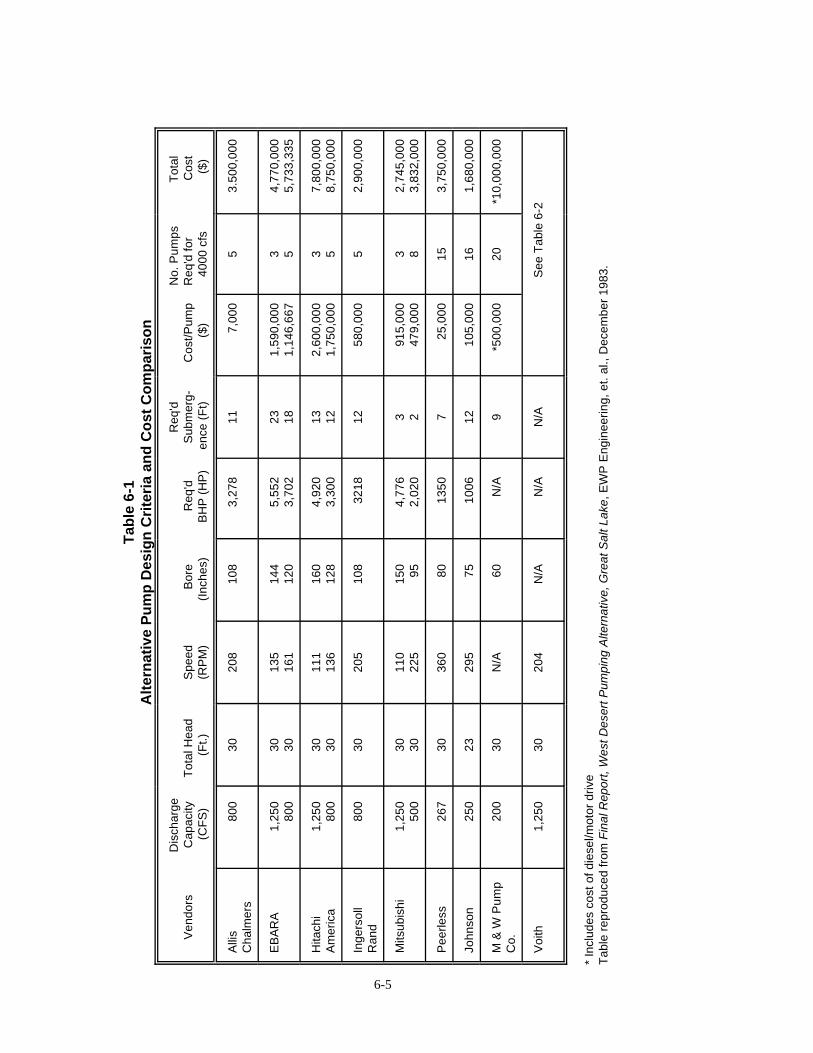
6-5
Tab
le 6
-1A
lter
nat
ive
Pu
mp
Des
ign
Cri
teri
a an
d C
ost
Co
mp
aris
on
V
endo
rsD
isch
arge
C
apac
ity
(CF
S)
T
otal
Hea
d(F
t.)S
peed
(RP
M)
Bor
e
(I
nche
s)
Req
'd
B
HP
(H
P)
Req
'dS
ubm
erg-
ence
(F
t)C
ost/P
ump
($)
No.
Pum
ps
Req
'd fo
r40
00 c
fs
Tot
al
C
ost
($
)
Alli
sC
halm
ers
800
30
208
108
3,27
8
117,
000
53.
500,
000
EB
AR
A1,
250
80
0
30 3013
516
114
4
12
0
5,
552
3,
702
23 18
1,59
0,00
01,
146,
667
3 54,
770,
000
5,73
3,33
5
Hita
chi
Am
eric
a1,
250
80
0
30 3011
113
616
0
12
8
4,
920
3,
300
13 12
2,60
0,00
01,
750,
000
3 57,
800,
000
8,75
0,00
0
Inge
rsol
lR
and
800
30
205
108
3218
12
580,
000
52,
900,
000
Mits
ubis
hi1,
250
50
0
30 3011
022
515
0
95
4,77
6
2,02
0
3 291
5,00
047
9,00
03 8
2,74
5,00
03,
832,
000
Pee
rless
267
30
360
80
13
50
725
,000
153,
750,
000
John
son
250
23
295
75
10
06
1210
5,00
016
1,68
0,00
0
M &
W P
ump
Co.
200
30
N/A
60
N
/A
9*5
00,0
0020
*10,
000,
000
Voi
th1,
250
30
204
N/A
N/A
N
/AS
ee T
able
6-2
* In
clud
es c
ost o
f die
sel/m
otor
driv
eT
able
rep
rodu
ced
from
Fin
al R
epor
t, W
est D
eser
t Pum
ping
Alte
rnat
ive,
Gre
at S
alt L
ake,
EW
P E
ngin
eerin
g, e
t. al
., D
ecem
ber
1983
.
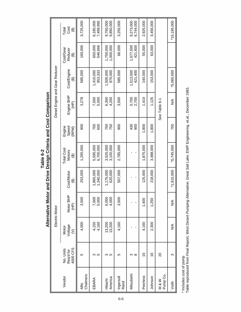
6-6
Tab
le 6
-2A
lter
nat
ive
Mo
tor
and
Dri
ve D
esig
n C
rite
ria
and
Co
st C
om
par
iso
n
Ele
ctric
Mot
or
Die
sel E
ngin
e an
d G
ear
Red
ucer
V
endo
r
N
o. U
nits
Mot
or
T
otal
Cos
t
Eng
ine
Cos
t/Gea
r
Tot
al
R
eq'd
for
Vol
tage
Mot
or B
HP
Cos
t/Mot
or
Mot
ors
Spe
ed
Eng
ine
BH
P
C
ost/E
ngin
e
R
educ
er
C
ost
400
0 C
FS
(V
)
(H
P)
($)
($
)
(R
PM
)
(H
P)
($)
($)
($
)
Alli
sC
halm
ers
54,
000
3,
500
25
3,00
01,
265,
000
900
3,
278
58
5,00
016
0,00
03,
725,
000
EB
AR
A3 5
4,15
0
4,16
0
7,00
0
5,00
0
1,86
5,00
01,
340,
000
5,59
5,00
06,
700,
000
750
60
0
7,50
0
5,00
0
1,41
0,00
095
3,33
365
0,00
054
6,66
66,
180,
000
7,49
9,99
5
Hita
chi
Am
eric
a3 5
13,2
00
13,2
00
6,00
0
4,00
0
1,17
5,00
062
0,00
03,
525,
000
3,10
0,00
075
0
750
6,
300
4,
200
1,
500,
000
970,
000
1,75
0,00
01,
000,
000
9,75
0,00
09,
850,
000
Inge
rsol
lR
and
54,
160
3,
500
55
7,00
02,
785,
000
900
3,
500
58
5,00
066
,000
3,25
5,00
0
Mits
ubis
hi3 8
-
-
-
-
-
-
-
-
430
90
0
5,70
0
2,70
0
1,51
3,50
042
1,40
01,
577,
500
421,
600
9,27
3,00
06,
744,
000
Pee
rless
154,
160
1,
400
12
5,00
01,
875,
000
1,80
0
1,41
0
140,
000
55,0
002,
925,
000
John
son
162,
300
1,
250
21
8,00
03,
488,
000
1,80
0
1,12
5
153,
000
63,0
003,
456,
000
M &
W
Pum
p C
o.20
See
Tab
le 6
-1
Voi
th3
N/A
N/A
*1,9
15,0
00*5
,745
,000
750
N
/A
*5
,065
,000
*15,
195,
000
* In
clud
es c
ost o
f pum
pT
able
rep
rodu
ced
from
Fin
al R
epor
t, W
est D
eser
t Pum
ping
Alte
rnat
ive,
Gre
at S
alt L
ake,
EW
P E
ngin
eerin
g, e
t.al.,
Dec
embe
r 19
83.
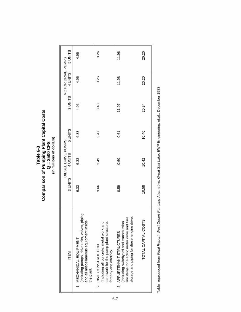
6-7
Tab
le 6
-3C
om
par
iso
n o
f P
um
pin
g P
lan
t C
apit
al C
ost
sQ
= 2
500
CF
S(i
n m
illio
ns
of
do
llars
)
ITE
M
DIE
SE
L D
RIV
E P
UM
PS
3 U
NIT
S
4 U
NIT
S
5 U
NIT
SM
OT
OR
DR
IVE
PU
MP
S
3 U
NIT
S
4 U
NIT
S
5 U
NIT
S
1.
ME
CH
AN
ICA
L E
QU
IPM
EN
T
(
Incl
udin
g pu
mps
, driv
e un
its, v
alve
s, p
ipin
g
a
nd a
ll m
isce
llane
ous
equi
pmen
t ins
ide
the
plan
t.
6.33
6.
33
6.33
4.
96
4.96
4.
96
2.
CIV
IL C
ON
ST
RU
CT
ION
(In
clud
ing
all c
oncr
ete,
met
al w
ork
and
ear
thw
ork
for
the
pum
p pl
ant s
truc
ture
,
fo
reba
y an
d af
terb
ay.
3.66
3.
49
3.47
3.
40
3.26
3.
26
3.
AP
PU
RT
EN
AN
T S
TR
UC
TU
RE
S
(
Incl
udin
g sw
itchy
ard
and
tran
smis
sion
line
item
s fo
r el
ectr
ic m
otor
driv
e an
d fu
el
s
tora
ge a
nd p
ipin
g fo
r di
esel
eng
ine
driv
e.
0.59
0.
60
0.61
11
.97
11
.98
11
.98
TO
TA
L C
AP
ITA
L C
OS
TS
10.5
8
10.4
2
10.4
0
20.3
4
20.2
0
20.2
0
Tab
le r
epro
duce
d fr
om F
inal
Rep
ort,
Wes
t Des
ert P
umpi
ng A
ltern
ativ
e, G
reat
Sal
t Lak
e, E
WP
Eng
inee
ring,
et.a
l., D
ecem
ber
1983

6-8
• With five units, the horsepowerrequirement of each diesel engine would beapproximately 3,800 BHP. This represents theupper range of standard design diesel engines. Engines larger than 4,000 HP are of specialdesign, requiring longer delivery time for engineand replacement parts.
• Units of this size, besides being morereadily available than larger units, can behandled by a mobile crane at times of installationand repair.
There was no advantage to selecting morethan five units for the following reasons:
• Installation cost increased in proportion tothe number of units.
• Required maintenance and total cost ofreplacement parts similarly tended to increase indirect relation to the number of units.
The cost of energy to pump the required totalamount of water remains substantially the same,regardless of the number of units selected for thisproject, because overall deficiencies in unit sizeswere comparable. Five units provided adequateflexibility for this type of operation.
If, and when, future conditions indicated aneed for less pumping capacity, operating fewerunits or for shorter periods would satisfy thisrequirement. If larger pumping capacity isrequired, an additional pump may have to beadded.
CostsCapital Costs - Capital costs were estimated
for the 4,000 cfs diesel engine drive and electricdrive pumping plant alternatives. These costs,including mechanical equipment, civilconstruction, and appurtenant structures for thepumping plant were estimated to be $15.88million for diesel driven pumps and $24.52million for motor driven pumps. The largedifference between the capital cost of the dieselengine drive and the electric motor drivenPumping Plant alternative was the cost of apower transmission line. Cost of the transmission
line was obtained from the Utah Power and LightCo. Cost of the major plant equipment wasreceived from several domestic and foreignmanufacturers. Cost of civil works was based onthe then prevailing unit prices in the Salt LakeCity area.
Cost of Operation - These costs were derivedby separately estimating cost of energy and costof operation and maintenance. Cost of electricitywas based on the Utah Power and Light Co.Schedule No, 9, which was found to be mostfavorable for this type of operation. Cost of dieselfuel was obtained from several wholesale dealersin the Salt Lake City area.
The total annual costs for diesel driven pumpswere estimated to be $6.21 million. Totalestimated costs for motor driven pumps was$4.20 million.
Plant Economics - Economic analysis of thediesel engine drive and electric motor drivealternatives compared total present worth of bothfor various periods of operation. Present worth ofcapitalized operation cost was computed using a30-year project life and a 7.5 percent discountrate.
These figures indicated that if the pumpingoperation started immediately after the plantcompletion, and lasted for more than five years,the electric motor drives were more economical.
Therefore, the final selection of the pumpdrives was to be based on the probability of themost likely hydrologic scenario. The electricdrives possibly were more economical in everycase if more favorable energy rates werenegotiated with the electric utility.
Evaporation Pond AlternativesThe 1983 report evaluated five configurations
of evaporation ponds, illustrated in Figures 6-2through 6-6. They were:
• Range Highline Alternative• Range Boundary Highline Alternative• Lakeside Lowline Alternative• North Railroad Lowline Alternative

6-9
• South Railroad Lowline AlternativeThese pond configurations included theinundation of land belonging to the U.S. AirForce.
A 1984 update report evaluated pondconfigurations which did not inundate Air Forceland. Illustrated in Figures 6-7 through 6-11,they were:
• Wendover Pond Alternative• Bonneville Pond Alternative• Newfoundland Pond Alternative (Counterclockwise Rotation)• Newfoundland Pond Alternative (Clockwise Rotation)• Boundary Ponds Alternative (Clockwise Rotation)
Basis of Comparison- - In the 1983 reportthe ponds were subjectively evaluated andcompared against each other. Characteristicsinvestigated for each configuration included:
• Amount of embankment required,• Minimum U.S. Air Force property inundation,• Minimum desert floor construction,• Anticipated construction time,• Actual survey data availableRecommended Alternative - The South
Railroad Lowline Alternative, with west and eastponds, was preferred. Pond characteristics were:
West Pond East PondWater SurfaceElevationsHigh 4218.3 Not availableLow 4217.6 Not availableAverage 4218 4214Area 374,000 acres 88,000 acres
@ 4218 @ 4214Volume 1,093,000 AF 285,000 AF
@4218 @4214Average Depth 2.92 ft. 3.24 ft.Discharge Structure WeirRadial gates 1,000 ft. long
Elevation 4217.5Peak Discharge 1,700 CFS 1,700 CFS
Basis of Comparison - The five pondconfigurations evaluated in the 1984 report(Those that did not inundate U. S. Air Forceproperty) are summarized in Table 6-4. Theywere compared on the following characteristics:
• Surface area• Volume (capacity)• Required inflow (pumping rate)• Construction of embankments• ExcavationPumping alternatives which would allow full
capacity operation for a GSL South Arm watersurface elevation of 4205 and 4208 wereevaluated. Estimated capital costs for each of thefive pond configurations are shown on Table 6-5.The following are summaries of each pondconfiguration in the 1984 report which did notinundate Air Force land.
Wendover Pond AlternativeThe Wendover Pond alternative was unique:
it would result in a pond with the largest surfacearea and, hence, the largest evaporation potentialthen any other alternative considered. TheWendover Pond would inundate all of the WestDesert’s depression storage below elevation 4218,except for the area between Lakeside and theNewfoundland Mountains. This alternativewould cover U.S. Air Force lands southwest ofthe Newfoundland Mountains, as well as east ofWendover (Wendover Bombing Range). It wouldalso submerge the Bonneville Speedway and SaltFlats.
Bonneville Pond AlternativeThe only difference between the Bonneville
Pond alternative and the Wendover alternativewas that the south of Highway 80 would not beinundated. The result was a loss of pond surfacearea and evaporation potential. Thisconfiguration did not cover the WendoverBombing Range, nor did it require that Highway80 or the Union Pacific Railroad be protectedfrom inundation from the south. This alternativesubmerged the Bonneville Salt Flats.
Counterclockwise Newfoundland Pond AlternativeThe Counterclockwise Newfoundland Pond
alternative was merely a continued retreat inpond size from the preceding alternatives. It didnot inundate the Bonneville Speedway or SaltFlats. As with the preceding two alternatives, itsubmerged the U.S. Air Force land southeast of

6-10
the Newfoundland Mountains, and routed the return brine flow through the Air Force land eastof the Newfoundlands.
Clockwise Newfoundland PondAlternativeThe Clockwise Newfoundland Pond
Alternative was of the same physical size as thecounterclockwise alternative. It differed only inthat the return brine was not routed through AirForce land, but circulated back to the Great SaltLake north of the Southern Pacific Railroadthrough a channel cut in the Hogup Mountains. This alternate continued to submerge Air Forceland southwest of the Newfoundland Mountains.
The flow pattern in this alternative, whichrouted the return brine to the lake withouttraversing Air Force lands east of theNewfoundlands, was applicable to the WendoverPond and Bonneville Pond alternatives as well,with only slight modifications. The difference incost between the two Newfoundland Pondalternatives was a cost applicable to otheralternatives for keeping the return brine flow offAir Force land.
It should be noted that by choosing thisalternate return brine alignment, a cutoff dam forstorm water would be created south of the IntakeCanal Barrier Dike. Any seepage into this areawould likewise be trapped. To alleviate thiscondition would require a storm water/seepagepump station. This would keep the entire areasouth of the Intake Canal basically dry, acondition which would benefit the Air Force,particularly as compared to the no-projectalternative.
Boundary Ponds Alternative The Boundary Ponds Alternative was of
significant interest because it did not inundatednor allow return brine flow across Air Force land.This alternative had the smallest pond surfacearea and, hence, the smallest evaporationpotential of any alternative considered.
Geotechnical Considerations Geotechnical and groundwater
investigations provided preliminary field andlaboratory test information necessary todetermine the engineering feasibility, preliminary
design, cost estimates and constructionscheduling for the proposed West DesertPumping Project.
The following is a summary of the results offield investigations, laboratory testing, andpreliminary design evaluations, and providesrecommendations related to geotechnical andgroundwater considerations. It should berecognized that this investigation waspreliminary in nature; detailed field andlaboratory information had not been developed.
Scope In accomplishing the above purposes, the
general scope of this investigation included thefollowing:
1. A field program consisting of:a. The drilling, logging and sampling of 18 borings located within the proposed pond areas, along the proposed dike and canal alignments, and at proposed alternate pumping station locations. The borings were drilled to depths ranging from 12 to 35 feet below the existing ground surface. Soil sampling and rock coring were performed. Piezometers were installed in a majority of these borings at the completion of drilling.b. The excavation, logging and sampling of 38 tests pits to evaluate potential
borrow areas and further evaluate dike and canal alignments.
c. A geologic reconnaissance of the projectarea and geologic mapping of critical lake bottom, shoreline and terrace areas was performed to provide information prior todrilling and test pit excavations. This reconnaissance was performed to evaluateborrow materials and the alignments of the proposed canal and dikes, and to
identify potential problems or hazards for the proposed project.
2. A laboratory testing program whichprovided preliminary information on theengineering characteristics of the existingembankment and foundation soils and bedrock,and the existing quality of the groundwater.

6-11
Figure 6-2Range Highline Alternative
Figure 6-3Range Boundary Highline Alternative

6-12
Figure 6-4Lakeside Lowline Alternative
Figure 6-5North Railroad Lowline Alternative

6-13
Figure 6-6South Railroad Lowline Alternative
Figure 6-7Wendover Pond Alternative

6-14
Figure 6-8Bonneville Pond Alternative
Figure 6-9Newfoundland Pond Alternative, Counterclockwise Rotation

6-15
Figure 6-10Newfoundland Pond Alternative, Clockwise Rotation
Figure 6-11Boundary Ponds Alternative

6-16
6-14
Tab
le 6
-4A
lter
nat
ive
Po
nd
Co
nfi
gu
rati
on
Alt
ern
ativ
esC
har
acte
rist
ic C
om
par
iso
ns
ITE
MW
endo
ver
Pon
d
Bon
nevi
lle
P
ond
C
lock
wis
e
N
ewfo
undl
and
C
ount
ercl
ockw
ise
New
foun
dlan
d
Bou
ndar
y
P
ond
Sur
face
are
a @
Ele
v. 4
218,
acr
es63
8,00
047
9,00
037
4,00
037
4,00
021
7,00
0
Vol
ume
@ E
lev.
421
8, a
cre-
feet
1,76
0,00
01,
440,
000
1,09
0,00
01,
090,
000
680,
000
Ann
ual e
vapo
ratio
n, a
cre-
feet
1,57
0,00
01,
140,
000
910,
000
910,
000
530,
000
Req
uire
d pu
mpi
ng r
ate,
CF
S4,
000
2,80
02,
400
2,40
01,
400
Exc
avat
ion
requ
ired,
cub
ic y
ards
8,53
0,00
06,
700,
000
8,61
0,00
05,
360,
000
6,92
0,00
0
Em
bank
men
t req
uire
d, c
ubic
yar
ds8,
475,
000
7,22
0,00
06,
000,
000
4,77
5,00
06,
400,
000
Dut
y ho
rsep
ower
12,8
008,
600
7,40
07,
400
4,30
0
Ann
ual d
iese
l con
sum
ptio
n, g
allo
ns6,
600,
000
4,40
0,00
03,
800,
000
3,80
0,00
02,
200,
000
Ann
ual f
uel c
ost
$5,6
00,0
00$3
,700
,000
$3,2
00,0
00$3
,200
,000
$1,9
00,0
00
CO
MP
AR
ISO
N F
AC
TO
RS
Ave
rage
pon
d de
pth,
feet
2.76
3.01
2.91
2.91
2.44
Ann
ual e
vapo
ratio
n2.
462.
382.
432.
432.
44
Fue
l cos
t ($/
acre
-foo
t eva
pora
ted)
$3.5
7$3
.25
$3.5
2$3
.52
$3.5
9
Tab
le r
epro
duce
d fr
om F
inal
Rep
ort,
Wes
t Des
ert P
umpi
ng A
ltern
ativ
e, G
reat
Sal
t Lak
e, E
WP
Eng
inee
ring,
et.a
l., D
ecem
ber
1983
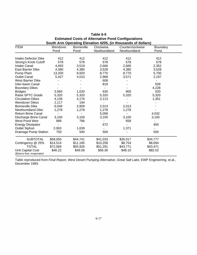
6-17
Table 6-5Estimated Costs of Alternative Pond Configurations
South Arm Operating Elevation 4205, (in thousands of dollars)ITEM Wendover Bonneville Clockwise Counterclockwise Boundary
Pond Pond Newfoundland Newfoundland Pond
Intake Defector Dike 412 412 412 412 412 Strong's Knob Cutoff 578 578 578 578 578 Intake Canal 4,693 3,519 2,666 2,666 2,352East Barrier Dike 4,380 4,380 3,528 4,380 3,528Pump Plant 13,200 9,920 8,770 8,770 5,700Outlet Canal 5,427 4,010 2,968 3,571 2,197West Barrier Dike - - 608 - -Inter-basin Canal - - 819 - 509Boundary Dikes - - - - 4,228 Bridges 3,560 1,020 630 900 520Raise SPTC Grade 5,320 5,320 5,320 5,320 5,320Circulation Dikes 4,139 4,176 2,113 - 1,351Wendover Dikes 2,117 194 - - -Bonneville Dike 6,049 3,909 2,013 2,013 -Newfoundland Dike 1,278 1,278 1,278 1,278 -Return Brine Canal - - 5,058 - 4,032 Discharge Brine Canal 3,100 3,100 3,100 3,100 3,100West Pond Weir 989 786 - 658 -Energy Dissipator - - 672 - 450 Outlet Siphon 2,063 1,639 - 1,371 - Drainage Pump Station 750 500 500 - 500
SUBTOTAL $58,055 $44,741 $41,033 $35,017 $34,777 Contingency @ 25% $14,514 $11,185 $10,258 $8,754 $8,694
TOTAL $72,569 $55,926 $51,291 $43,771 $43,471 Unit Capital Cost $46.22 $49.06 $56.36 $48.10 $82.02($)/acre-foot, evaporated
Table reproduced from Final Report, West Desert Pumping Alternative, Great Salt Lake, EWP Engineering, et.al.,December 1983.

6-18
Table 6-5 (Continued)Estimated Costs of Alternative Pond Configurations
South Arm Operating Elevation 4208, (in thousands of dollars)
ITEM Wendover Bonneville Clockwise Counterclockwise BoundaryPond Pond Newfoundland Newfoundland Pond
Intake Defector Dike 412 412 412 412 412 Strong's Knob Cutoff 578 578 578 578 578 Intake Canal 3,160 2,459 1,783 1,783 1,582 East Barrier Dike 4,380 4,380 3,528 4,380 3,528 Pump Plant 13,200 9,920 8,770 8,770 5,700 Outlet Canal 5,427 4,010 2,968 3,571 2,197 West Barrier Dike - - 608 - - Inter-basin Canal - - 819 - 509 Boundary Dikes - - - - 4,228 Bridges 3,560 1,020 630 900 520 Raise SPTC Grade 5,320 5,320 5,320 5,320 5,320 Circulation Dikes 4,139 4,176 2,113 - 1,351 Wendover Dikes 2,117 194 - - - Bonneville Dike 6,049 3,909 2,013 2,013 - Newfoundland Dike 1,278 1,278 1,278 1,278 - Return Brine Canal - - 5,058 - 4,032 Discharge Brine Canal 5,616 5,616 5,616 5,616 5,616 West Pond Weir 989 786 - 658 - Energy Dissipator - - 672 - 450 Outlet Siphon 2,063 1,639 - 1,371 - Drainage Pump Station 750 500 500 - 500
SUBTOTAL $59,038 $46,197 $42,666 $36,650 $36,523
Contingency @ 25% $14,760 $11,549 $10,667 $9,163 $9,131 TOTAL $73,798 $57,746 $53,333 $45,813 $45,654
Unit Capital Cost $47.01 $50.65 $58.61 $50.34 $86.14 ($)/acre-foot, evaporated
Table reproduced from Final Report, West Desert Pumping Alternative, Great Salt Lake, EWP Engineering, et. al.,December 1983.
6-19
3. An office program which includedreviewing the existing geological and engineeringdata, discussing data and canal construction withcontractors and evaporation pond companieswho were familiar with the proposedconstruction techniques, engineering analysesand the preparation of summary reports.
Summary of ConclusionsThe following general conclusions were
developed as a result of this preliminarygeotechnical and groundwater investigation forthe West Desert Pumping Alternative:
1. Based upon the geotechnical andgroundwater considerations, the proposed WestDesert Pumping Project was feasible.
2. Geotechnical considerations andconstruction scheduling indicated that thepreferred alignments for the proposed IntakeCanal and East Pond Dike would be locationswhich minimize dike heights due to the lowstrength clays in the area between Lakeside andHogup Ridge.
3. The foundation soils upon which theproposed West Pond, East Pond, associated dikesand canals were established were primarily siltyclay and clay soils which exhibited low strengthand permeability and high compressibilitycharacteristics. Due to the low permeability,seepage through the foundations would be verylow.
4. It was recommended that, where possible,dikes be constructed of adjacent lakebed claymaterials to keep seepage through the dikes to a minimum and to minimize importation ofmaterial. If the dikes could not be constructed oflakebed clays, imported granular dikes wererecommended. An impermeable cutoff trenchwould be constructed through the center of thedikes keying into the lakebed foundation soils orby placing an impermeable clay blanket on thepond side of the dikes.
5. Preliminary evaluation of requiredfreeboard for the dikes indicated that, based on
wind velocity data, the necessary freeboard forsetup and wave action would be four to six feet,depending on the dike location. Based on thefetch distances and the higher density of thepond water, slope protection was recommendedon all dike slopes adjacent to the ponds. Theslope protection material would consist of coarse,sandy gravel and cobble materials imported fromborrow sources located at higher elevationsadjacent to the lakebed deposits.
6. Potential problem soils identified alongproposed canal and dike alignments consisted oflow-strength clays, gypsiferous sand dunes andoolitic sand dunes. Generally, the lower strengthclay occurred in areas of lower surface elevation.The dune materials generally were observed to bein a relatively loose condition and exhibitedmoderate permeability and compressibilitycharacteristics. In addition, the gypsiferous duneswere somewhat water soluble.
7. Construction of the proposed dikes wasvery sensitive to the shear strengths of thefoundation soils. In general, shear strengths ofthe foundation materials below all the dikes,except the Lakeside Dike, exhibited adequatestrengths for the proposed embankment heights. However, due to the relatively low shearstrengths near the Lakeside area and theproposed relatively high dikes which werenecessary along that dike alignment, stagedconstruction of that dikes would be necessary. Itwas recommended that the foundation soil shearstrengths be further defined if the project wasauthorized, so that a more detailed stabilityevaluation could be performed in the Lakesidearea.
8. Seepage through the proposed dikesconstructed of lakebed soils and established uponlakebed foundation materials would be less thanone gallon per minute per mile of dike. Pondedwater and seepage loses from the proposedreservoirs would result in groundwater levelincreases of less than one to two feet belowexisting facilities adjacent to the proposed ponds.

6-20
Therefore, the impact of the seepage on existingfacilities would be very minimal. 9. The installation of a Pumping Plant at anyof the alternative pumping locations wouldprobably require dewatering, and blasting wouldbe necessary to excavate through bedrockmaterials where they were encountered. 10. Due to the extremely large project areaand the difficulty to obtain access to significantand important critical areas for the project, thepreliminary conclusions stated here weredeveloped from a limited field and laboratoryinvestigation and primarily based on experiencein similar type soils. If this project wereauthorized, more detailed geotechnicalsubsurface elevations would have to beperformed within critical areas. Specifically, thesecritical areas occurred at the proposed PumpingPlant location and along the alignment for theLakeside Dike and Canal.
Hill Air Force RangeBy way of background, the Hill Air Force
Range was initially established in direct supportof Air Force Logistics Command (AFLC) testingrequirements and used extensively in support ofDepartment of Defense (DOD) munition testingprograms since it was withdrawn from the publicdomain in 1941. Munition testing on the rangeis divided into three categories: (1) munitionflight testing, (2) munition ground testing, and(3) large and small missile motor firings. Serviceengineering test flights are also performed to testaircraft and ordinance modifications thatgenerally result in weapon system improvements.The range is also used for tactical training forpilots in air-to- ground exercises.
The overall investment in rangeinstrumentation and facilities alone was in excessof $40 million. Annual payroll and localcontracts associated with the range weresubstantial. Many missions were top securityefforts, and dry land and accessible target areas
were essential. The range is also an essential partof a DOD Range Complex consisting of Hill,Wendover, and Dugway. This is one of thelargest overland range complexes in the country.The non-accessibility/utilization of targets orreduction of available targets posed by wet targetareas of access thereto would pose severescheduling problems for the Air Force, thesolution of which would be the curtailment,elimination or relocation of essential DOD tests.
The general area which would be affected bythe West Desert Pumping Alternative wasactively being used for the delivery of a largevariety of munitions. The testing, training andhazardous operation accomplished was vital tomaintaining a viable tactical/strategic force. Theworkload at the range taxed the availableinstrumentation and facilities to the limit therebynecessitating expansion to support ongoing andprojected future operations.
The overall Hill Air Force Range has beenused for different types of live munitions over thepast 42 years. Many of these extremelyhazardous munitions may not have exploded andlie at various depths below the surface of theground. Dredging dikes, canals, etc., through thisarea would be a critical undertaking, and mayseriously jeopardize the safety of personnel andequipment. Such activity would likely reduce theflexibility of the range to respond to the variousoperational, training and testing functions.
The West Desert Pumping alternative wouldinundate several non-critical targets. In additionto inundating these targets, it was possible thatintroducing water to adjacent areas would raisegroundwater level due to capillary action andaffect other targets. The need to minimize theimpact to the Hill Air Force Range in the desertwest of the Great Salt Lake was a major objectiveof the engineering feasibility study.
6-21
Coordination With Southern Pacific Transportation Company
GeneralDirect impacts on property owners in the
project area were mostly focused on facilitiesowned and operated by the Southern PacificTransportation Company (SPTC). In the area ofanticipated heaviest construction, (that is, fromthe intake works near the existing breach to theWest Desert Pond) there would be four crossingsof the Southern Pacific railroad tracks andnumerous other interactions with SouthernPacific's facilities. This section more clearlydelineated the interaction with and participationof Southern Pacific Transportation Company inthe project.
Specific IssuesProposed design concepts were discussed
with the SPTC Engineering Department. Ingeneral, SPTC indicated a strong interest incontrolling the Great Salt Lake level and inimplementing the West Desert Pumping Project.The position of the SPTC on specific projectcomponent issues was:
1. The arrangement of the intake at thecauseway breach was acceptable to SPTC. Theproximity of the deflector dike to the causewaywould not cause right-of-way conflicts. A primaryconcern was with the replacement of riprap thatmight be lost due to wave action. Replacementcould be handled by the SPTC on a costreimbursable basis.
2. The SPTC would make its road along therailroad tracks available for access to thePumping Plant on Hogup Ridge duringconstruction and later for operation andmaintenance. The railroad would provide, on acost reimbursable basis, qualified people tocontrol the access.
3. The SPTC did not anticipate difficulty inproviding and maintaining a diesel fuel deliveryfacility on a cost-reimbursable basis. A doublerailroad spur could be built near the Pumping
Plant to accommodate two trains of tank cars;SPTC was of the opinion that storage of fuel intank cars would be more economical than storagein an underground tank. A week's supply couldbe stored. Alternately, the fuel could be stored inan underground tank. The final solution was tobe adopted in the detailed design phase after thecost optimization of both alternatives wasevaluated.
4. The SPTC was willing to design allbridges required to cross breaches in the railwayembankment, based on spans as directed byproject requirements on a cost reimbursablebasis. Alternately, the bridges could be designedby the designers of the West Desert PumpingProject with SPTC participation and approval. Scheduling of design and construction,particularly rail traffic handling problems duringconstruction, would need to be carefullyevaluated and agreed upon.
5. Design of the protection of the railroadembankment through the West Pond would haveto be coordinated with the SPTC and itsgeotechnical consultant. The SPTC indicatedthat dikes would be required versus raising thegrade. Final design would depend ongeotechnical and hydraulic criteria, ability ofSPTC to raise grade and the long-term protectionand stability of the railroad embankment.
6. The SPTC was prepared to act asconstruction manager for features of the projectaffecting its operation. Construction of thecauseway breach would serve as a model forelements of the project which impacted therailroad.
7. The SPTC was prepared to furnish quarrymaterials from its Lakeside quarry on a costreimbursable basis for use in the project. Thismaterial would meet riprap, ballast and quarryreject requirements for much of the embankmentand dike work from Lakeside to the West Pondalong the railroad alignment. The material wasnot suitable for concrete aggregate.
8. The SPTC did not see serious conflicts

6-22
if its facilities were used for construction access.This matter would be addressed during thedetailed design stage of the project.
9. The SPTC was prepared to make space atLakeside available for housing the constructioncrews on a cost reimbursable basis. Depending onrequirements, the power supply for this campmight require upgrading by the construction of atransmission line from the Air Force base.
The above issues needed to be verified indetail with SPTC before start of final design. Adetailed agreement between the SPTC and thestate of Utah would probably be required toadequately define the responsibilities of bothparties. Of particular interest werereimbursement provisions, schedules, reviewprocedures, and common use of SPTC facilitiesduring and after construction.
Summary and ConclusionsThe engineering feasibility report completed
in 1983 on the GSL/West Desert PumpingAlternative was based on work conducted byEckhoff, Watson and Preator Engineering(EWP); International Engineering Company, Inc.(IECO); and Dames & Moore (D&M). Principalassignments were management and civilengineering, EWP; pumping and power systems,IECO; and geotechnical and GW hydrology,D&M.
Major conclusions and recommendationswere:
1. Based on geotechnical and groundwaterconsiderations, the proposed project was feasible.
2. The natural lake bed clay materials whichpredominate in the West Desert could be usedfor much of the canal construction, which wouldminimize the costs of much of the earthwork. They were also of relatively low permeability andwould restrict the seepage of water through thedikes.
3. In areas of high dike construction, such asnear Lakeside, staged construction would benecessary.
4. Seepage through dikes constructed of lakebed soils should be less than 1 GPM/mile.Ponding and seepage from the proposed pondswould result in groundwater increases of lessthan one to two feet. Therefore, the impacts ofseepage on existing facilities would be minimal.
5. Because of access and time limitations,only preliminary geotechnical field studies andlaboratory investigations were conducted. If theproject was authorized, significant geotechnicalinvestigations were to be performed in criticalareas.
6. Although the required pumping facilitieswould be located in an unusual, remote andharsh environment, the facilities could beconstructed without significant delays oradditional costs, using conventional pumps,drivers and control systems.
7. Pumping Great Salt lake brines would notpose difficult problems.
8. Ordinarily, it would be preferable toutilize electric motors as the pump drivers, evenwith the large size of the recommended units. However, the study showed that diesel drivesystems would have substantially lower capitalcosts, due to the need for long electricaltransmission lines for this project. Diesel driverswere, therefore, recommended.
9. The recommended pumping facilitywould have a nominal capacity of 2,400/2,500cubic feet per second and lift the GSL brineapproximately 20 feet. Total installed powerwould be about 10,000 HP. Four to six pumpswould be recommended.
10. There did not appear to be other factorswhich would invalidate the study's conclusions ofthe general and overall engineering feasibility ofthe proposed GSL/West Desert PumpingAlternative.
11. A variety of sizes and configurations ofponds, dikes, canals and control facilities wereinvestigated in the study. Major evaluationfactors invoked in the analyses were:

6-23
a. Effectiveness in evaporating GSL brine (maximize).b. System costs (minimize).c. Construction on Air Force Test Range properties (minimize).d. Construction time (minimize).
12. The recommended alternative, based onthe above evaluation factors, was designated theRailroad Lowline Alternative (South Option),because the Intake Canal extended across thedesert to the Pumping Plant at Hogup Ridge inan alignment which was parallel to and south ofthe Southern Pacific Railroad tracks.
13. Costs of the recommended alternative,component by component, are shown below.
14. Operating costs would be approximately$4 million per year, of which 90 percent wouldbe for fuel costs for the pumps.
15. The proposed system would have thecapability of evaporating 1,060,000 acre-feet peryear. Including the effects of initial storage, thesystem would reduce the level of GSL by 3.1 to3.2 feet within a three-year period.
16. Because of the extensive federal landwhich would be impacted by the proposedproject, an Environmental Impact Statement wasconsidered. The BLM and the Air Force stronglysupported the preparation of an EIS. Thisprocess would take approximately one year tocomplete and cost an estimated $600,000.
17. An extremely long project scheduleresulted from a decision to postpone otherproject activity until after completion of the EIS.Allowing for reasonable winter delays, thedesign/construction period following the EIScompletion would be approximately 21 months,giving an overall project schedule of 33 months. This schedule assumed a "fast track" process thatmight entail extra costs because of inherentuncertainties.
18. If the engineering efforts were initiatedat the same time as the NEPA (EIS) process,considerable time could be saved on the overallproject schedule. It was estimated that the time
could be reduced 25 months, providing relief forthe 1986 GSL peak. This process would alsoassure adequate time to conduct requisite fieldstudies and easement and right-of-way work. Costs would also be more under control.
19. The estimated cost of the engineering was$2.3 million.
20. An interim construction program wasrecommended that could:
a. Result in the retention of substantial runoff from the West Desert, andb. Provide for the first stage of construction of the East Pond Dike.
These elements were part of the recommendedprogram of construction.
Component Costs
Component Return South Return North ($1,000) ($1,000)
Pump Station Intake Canal 2,168 2,168Pumping Plant 8,770 8,770Pump Station Discharge Canal 6,546 6,546GSL Isolation Dikes 5,269 2,247Railroad Dikes 3,1693,169Bonneville Dikes 2,013 2,013Newfoundland Dikes 1,278 1,278East Pond Dike 5,188 5,188Return Brine Canal 100 -Railroad Bridges 3,680 2,430West Pond Weir 658 658East Pond Outlet 585 -Highline Siphon - 1,371High Water Penalty 500 500
Subtotal $39,924 $36,338Contingency @ 25% $9,981 $9,805TOTAL $49,905 $45,423
C Because of the nature of the West Desert constructionenvironment and the remaining field work, thecontingency factor had been set at 25 percent.
Approximately 300,000 acre-feet of runofforiginated in the West Desert during 1983. Retaining and evaporating this amount of runoff

6-24
could reduce the average level of GSL about 1/4-foot. The first impacts of the project could thusbe advanced one year. -
References
Final Report, West Desert Pumping Alternative,Great Salt Lake, Eckhoff, Watson and PreatorEngineering, et. al., December 1983.
Final Report, West Desert Pumping Alternative,Eckhoff, Watson and Preator Engineering,October 1984.
1984 Update West Desert Pumping Alternative -Great Salt Lake, Eckhoff, Watson and PreatorEngineering, October 1984.
Facilities and Appurtenances Study, Related to theE.I.S for West Desert Pumping Alternatives, Eckhoff,Watson and Preator Engineering, et. al., March1985, Chapter 4.

7-1
Chapter 7
Environmental Impact Statement
Actions 1 Bureau of Land Management 1
U. S. Air Force 1 Summary of Alternatives 1
Alternative 1 - No Action 2 Alternative 2 - West Desert
Pumping Project 2 Alternative 3 - Diking to Protect Critical Facilities 3
ActionsThe Utah Division of State Lands and Forestry
entered into a contract with BIO/WEST,INCORPORATED, of Logan, Utah, on January 31,1985, to prepare an Environmental ImpactStatement (EIS) for the proposed Great Salt LakeWest Desert Pumping Alternative.
In accordance with the National EnvironmentalPolicy Act (NEPA), the EIS was prepared as thedecision document for the Bureau of LandManagement (BLM) and the U.S. Air Force (USAF).The BLM was the lead agency for the EIS, and theUSAF was the cooperating agency. In February 1986the Draft EIS was released for public review andcomment. The Final EIS was released in July 1986.
Bureau of Land ManagementOn June 20, 1986 (effective Date of Grant), the
BLM granted the state of Utah, Division of WaterResources, a 50-year right-of-way to construct,operate, maintain and terminate the Great Salt LakePumping Plant, Intake Canal and Dike, OutletCanal, Retention Dike and Evaporation Pond onpublic lands.
U. S. Air ForceThrough a letter on November 5, 1986, from
the Department of the Army, Sacramento District,Corps of Engineers, the Division of Water Resourceswas approved to mobilize and start construction ofthe Newfoundland Dike and appurtenant facilitiesfor the West Desert Pumping Project on lands at theHill Air Force Range (HAFR). This right-of-entrywas issued pursuant to an emergency exemptiongranted by the President’s Council on environmentalQuality, dated May 27, 1986, and subject to termsand conditions of formal instruments to beformalized at a later date. The right-of-entry was ashort-term (two-year) right granted under emergencyconditions, which was terminated at the end of theMay 1987 to June 30, 1989, pumping period.
Summary of AlternativesThe state of Utah filed for a right-of-way to use
public and U.S. Air Force lands for the West Desert

7-2
Pumping Project. The major purpose of the projectwas to prevent flooding around the Great Salt Lake(GSL) due to rising lake levels. The project wouldutilize federal lands on which to construct apumping plant and associated canals and dikes tocreate an evaporation pond in the West Desert.Water would be pumped from the GSL to the WestDesert Pond for evaporation. The West DesertPumping Project discussed in the Final EIS was amodified version of the project discussed in theDraft EIS.
The Southern Pacific Railroad Causeway wasbreached in 1984, which lowered the south arm ofthe lake about one foot. Diking was initiated inseveral areas to protect critical facilities. Additionallake management options were studied by the stateat a feasibility level. These studies prompted thestate to propose construction and operation of theWest Desert Pumping Project as the most reasonablealternative to meet the immediate need for floodcontrol.
A number of other flood control measures wereinvestigated by the state, but after evaluation it wasdetermined they would be either ineffective inpreventing flooding, would take too long to build, orwould be too expensive. The only reasonablealternative was to dike critical facilities around thelake to protect human health and safety. The dikingalternative was, therefore, developed for the EISfrom feasibility studies on diking that werecontracted by the state.
In addition, a no action alternative wasanalyzed as required by the NEPA. In order tocompare pumping, diking and no action alternatives,the lake rise to elevation 4215 scenario wasdeveloped. It assumed that inflow to the lake wouldbe at about 170 percent of average from years 1986to 2000. This rate of inflow would make the GreatSalt Lake rise to elevation 4213 by 1989 and to4215 by 2000, as compared to the peak 1986 levelof about 4212. Lake elevation would then drop to4205 by the year 2010. A lake elevation scenario at4217 was also developed as a worst case situation.
Alternative 1 - No ActionThe no action alternative assumed that permits
for the West Desert Pumping Project would not beissued by the BLM and the Air Force. For analysispurposes, it also assumed that no additional floodcontrol measures would be implemented and thatunchecked flooding around the GSL would occur.Any existing flood control structures would beovertopped rather rapidly. For example, the UnionPacific Railroad grade along the south shore of theGSL would protect I-80 and other facilities untilelevation 4213-4214, when it would be overtopped.
Impacts of this alternative would allow the GSLto rise unchecked. Numerous areas along the eastshore would be flooded, affecting farmlands,wetlands, wildlife habitat, recreation, economic andcultural resources. Interstate 80 along the southshore of the GSL would be inundated, as would theUnion Pacific Railroad grade and the SouthernPacific Railroad Causeway, creating majortransportation problems. All of the evaporativeindustries around the lake would be flooded, as wellas much of the Rose Park residential area and severalwaste water treatment plants and refuse site. Costsof the damages would exceed $1 billion.
In addition, fog and low clouds would increaseas the lake became larger, affecting weather along theWasatch Front and in the West Desert, but only inthe winter months. This poor weather would alsoreduce the amount of time the Air Force could usethe Utah Test and Training Range (UTTR).
It was likely that some flood control measureswould be taken; but for analysis purposes, none wasincluded in the alternative.
Alternative 2 - West Desert Pumping ProjectThis was the propose action and involved
construction of several structures in the areas west ofthe GSL. The project had been modified sincepublication of the Draft EIS; some portions of themodified project were still being designed whenconstruction started. A Pumping Plant would belocated adjacent to, and on the south side of, theSouthern Pacific Railroad grade at Hogup Ridge.Water would be pumped directly from the north armof the lake, although canals would need to bedredged as the lake receded. A trestle would be

7-3
constructed so that water could flow under therailroad grade from north to south to the PumpingPlant. The Pumping Plant would utilize three pumpsdesigned to pump up to 3,500 cubic feet of water persecond up about 23 feet to a discharge channel. Thepumps were originally planned to be diesel powered;however, plans were changed to power the pumps bynatural gas. The discharge channel would transportwater to the north side of the railroad grade near thenorthern end of the Newfoundland Mountains. Thewater would then spread out and move south underthe railroad grade and along the west side of theNewfoundland Mountains. Two dikes, theBonneville Dike and the Newfoundland Dike, wouldcontain the pond. The Bonneville Dike would keepthe pond, called the West Pond, from covering I-80and from flooding the Bonneville Salt Flats. TheNewfoundland dike would extend from the southernend of the Newfoundland Mountains southeasterlyto high ground across the mud flats. A control weirin the Newfoundland Dike would maintain themaximum level of the West Pond at about elevation4217 and at a size of about 320,000 acres.
Water would flow over the Newfoundland Dikeweir and then by the lay-of-the-land would flow backto the north arm of the lake. This would result inscattered ponding in low areas between theNewfoundland Mountains and the north arm. Thewater would flow under the Southern PacificRailroad grade via a trestle to be built for the projectnear Lakeside. Several figures and diagrams showingthe project layout can be found in the Draft EIS.
Most of the material for the dikes would comefrom material sites. Material for the NewfoundlandDike would come from new material sites at thesouthern end of the Newfoundland Mountains.Material sites for the Bonneville Dike would belocated near either end of that dike and wouldinclude existing pits used by the Department ofTransportation. The project would cost about$55 million to build, and construction would takeapproximately one year. The work force would notexceed about 200 persons.
Under the elevation 4215 scenario, the WestDesert Pumping Project would hold the Great SaltLake at elevation 4212, so no additional flood
control measures would be required. Under the 4217scenario, the lake would still rise to elevation 4215and additional flood control measures along the eastshore would probably be needed.
During the design studies for the project, costsand designs to control potential seismic (earthquake)concerns were included, as were costs to repair anylocal roads used to haul material to the dikes.Another proposed mitigation measure would be tohave a qualified archaeologist conduct surveys inareas proposed for surface disturbance and toconduct random surveys of the inundated areas inthe West Desert.
Impacts of this alternative to the West Desertwould be fairly minor, since most of the areaimpacted is mud flat. Kaiser Chemical may bebenefitted by increased brine flow caused bygroundwater recharge from the West Pond. Grazingaccess to the Newfoundland Mountains andsouthern Hogup Ridge would be restricted by thedischarge channel.
Under the 4215 scenario the lake wouldessentially not rise from levels at the time, creatingsignificant flood control benefits to shoreline areas.All sectors would be benefitted, especially thetransportation sector. Under the 4217 scenario, mostof the no action flooding impacts would still occurand few benefits would occur.
The major negative impacts of the project wouldbe an increase in winter fog around the GSL and anincrease in precipitation along the Wasatch Front.This would impact the Air Force operations on theUTTR, but for only a few days. Also, the West Pondand scattered ponding in the East Pond arearesulting from flow back to the lake would restrictflight operations, because Air Force regulations donot allow low level flights over open water whichwould endanger pilots who eject from their aircraft.
Alternative 3 - Diking to Protect Critical FacilitiesThis alternative involved building and/or raising
dikes along the GSL to protect critical facilities,primarily sewage treatment plants to elevation 4215or 4217, depending on the lake rise scenario. Thisalternative assumed that seven dikes would be built

7-4
to protect those facilities. The Union PacificRailroad grade along the south shore of the GSLwould protect I-80 and other facilities until elevation4213-4214, so it was considered as another existingdike. The eight dikes considered in the EIS includedthe Corinne, Perry, Plain City, and Little MountainWaste Water Treatment Plant dikes and SouthDavis, Rose Park, South Shore, and UPRR/I-80dikes. The South Davis Dike would protect sewagetreatment plants and refuse disposal sites west ofBountiful. The Rose Park Dike would protect areasaround the mouth of the Jordan River near the RosePark residential area. The South Shore Dike wouldprotect I-80 near the Saltair Resort. Material forconstruction of these dikes would come fromWasatch Front sources. The Union Pacific Railroadgrade along the south shore the GSL would protectI-80 and other facilities until elevation 4213-4214,after which it would be abandoned and the freewayand railroad would be routed to higher ground.Dikes built by AMAX Magnesium and AmericanSalt Company also protected portions of the UnionPacific grade, I-80, and Timpie WaterfowlManagement Area north and west of Grantsville.This alternative would protect the areas immediatelybehind the dikes, but no other areas.
This alternative would have some negativeimpacts, but like the pumping action it primarilyprovided flood control benefits. Benefits of diking,however, would be considerably less than WestDesert Pumping Project under the elevation 4215scenario. Major flood damage to mineral industries,transportation corridors and farmland would stilloccur under this alternative.
The major negative impact would be the loss ofdeer winter range due to borrow material removalfrom sites along the Wasatch Front. Under the 4217scenario, even more extensive flooding impactswould still occur. -

8-1
Chapter 8
West Desert Pumping Project
Permit Agreements and Mitigation
U.S. Air Force 1 Archeological Studies 2
Department of Interior, Bureau of Land Management 2
U.S. Army Corps of Engineers 2 Utah State Division of
Environmental Health, Bureau of Water Pollution Control 2
Air Quality 2 Magnesium Corporation of America 3
Mountain Fuel 3
A number of permits, rights-of-way andagreements were required to allow the state of Utahto construct and operate the West Desert PumpingProject. Most prominent were those required by theU.S. Air Force, U.S. Army Corps of Engineers, andBureau of Land Management. Archeological studieswere also required.
U.S. Air ForceThe U. S. Air Force required the state of Utah
to obtain its right-of-way permit to pump water ontoAir Force lands, specifically the Utah Test andTraining Range in Tooele and Box Elder counties.Permission was also required for construction on AirForce lands, such as the Newfoundland Dike, andstudies such as the excavation of the Donner-ReedWagon Box Mound Site and documentation of theHastings Trail/Donner-Reed experience.
A temporary two-year U.S. Air Force right-of-way permit to construct the Newfoundland Dikeportion of the West Desert Pumping Project wasissued in November 1986. It was documented onlyby letter, and later informally extended through theproject’s pumping period. Other elements of thepumping project were already under constructionwhen this right-of-way was issued. If the pumpingproject were ever renewed, another right-of-waypermit would have to be issued. The permittingprocess involved at least two Air Force majorcommands and, potentially, the Department of theAir Force. The right-of-way permit allowed operatingthe pumping project down to a south arm elevationof 4208 feet above mean sea level. Later, inFebruary 1988, the permitted level was lowered to4206.7.
The Air Force had several concerns: mostprominent was safety. Air Force officials contendedthat a large body of water at the range woulddegrade rescue efforts for downed pilots in the areaand affect their ability to survive. And at night, thewater would contribute to pilot disorientation. Inaddition, Air Force officials believed the water wouldincrease the bird population which would behazardous to aircraft flights through the area.Officials conceded, however, that the return brinecanal would reduce the water surface, thus reducing

8-2
safety and other concerns.Air Force officials were also concerned that
pumping water into the West Desert would damagetarget complexes and affect training. And pumpingwould impact the Air Force’s ability to find andclean up explosives that might be in the floodedarea.
Occasional fog was another concern. And if thestate wished to pump water into the West Desert inan effort to manage the lake level for non-emergencypurposes, Air Force officials indicated they would beless likely to accept adverse impacts that mightresult. Further encroachment on Air Force lands forlake management purposes would be a majorconcern.
Archeological StudiesArcheological studies were implemented
through a Memorandum of Agreement between theU.S. Air Force, the Utah State Historic PreservationOfficer, and the state Advisory Council on HistoricPreservation. The efforts satisfied requirements ofUtah’s National Historic Preservation Act of 1979.
Sites with cultural and anthropologicalimportance that were affected by the pumpingproject were two cave sites on the NewfoundlandMountains, the Floating Island cave site, theDonner-Reed Wagon Box Mounds site, and theHastings Trail and Donner-Reed experience.
The pumping project avoided the two cave sitesin the Newfoundland Mountain area, but they wereclassed as significant because of their connection toother excavated sites in the Great Basin area. Theyalso are registered by the Utah State Historic andPreservation Office.
The project also avoided the Floating IslandCave site that is on Bureau of Reclamation land. Itwas determined the cave was not associated with theDonner-Reed or Hastings trails, but its proximityand the history of archeological looting in the arealed to additional excavation.
The Donner-Reed Wagon Box Mound site wascovered by water in the evaporation pond west of theNewfoundland Mountains. The site was excavatedby the state between October 10 and December 18,1986.
The Hastings Trail and the Donner-Reedexperience was also documented by aerialphotography. A portion of the trail wasintermittently visible and was criss-crossed by severalpioneer parties known to have traveled the HastingsTrail.
Department of the Interior, Bureau ofLand Management
The Bureau of Land Management granted aright-of-way permit for use of about 200,000 acres ofpublic land under authority of Title V of the FederalLand Policy and Management Act of 1976.Additional use authorizations were also required forconstruction activities. As mentioned in Chapter 7,the bureau granted a 50-year right-of-way to publiclands to construct, operate, maintain and terminatethe West Desert Pumping Plant, Intake Canal andDike, Outlet Canal, Retention Dike and EvaporationPond.
U.S. Army Corps of EngineersThe U.S. Army Corps of Engineers granted a
404 Permit for the Southern Pacific RailroadCauseway breach and pumping project constructionin the waters of the Great Salt Lake under authorityof the Federal Clean Water Act of 1977 and theFederal Water Pollution Control Act Amendment of1972.
Utah State Division of EnvironmentalHealth, Bureau of Water Pollution Control
The Bureau of Water Pollution Control issued apermit to discharge into state waters under authorityof Utah Code Annotated SS73-14-5, 73-14-10.
Air QualityAn air quality approval order was required by
Utah Air Conservation Regulations and the Utah AirConservation Act. It was issued in October 1986.Major concern was with emissions from the threenatural gas fueled engines at the pumping stationand two natural gas fueled electric generators toprovide on-site electrical power. The initialcompliance inspection at the pumping station and

8-3
periodic inspections by the Utah Department ofHealth, Division of Environmental Health, Bureauof Air Quality, found the Pumping Plant compliedwith Utah’s air quality regulations.
Magnesium Corporation of AmericaIn 1987 the Magnesium Corporation of
America, previously called AMAX MagnesiumCorporation, was allowed to extend the Inlet Canalto the Pumping Plant approximately 9,000 feet bydredging in an effort to extend the company’s brinerecovery efforts. In doing so, the company had tocomply with the U.S. Army Corps of Engineers 404Permit. This effort was also coordinated with theBureau of Land Management and the SouthernPacific Transportation Company. Estimated cost ofthis project was $700,000.
The magnesium company was also allowed toconstruct a multi-million dollar brine extractioncanal project near Knolls in 1987 to divert brinefrom the West Desert Pond to its processing facility.
Mountain FuelThe Magnesium Corporation of America
provided a right-of-way, a pipe storage lot and freshwater to hydrostatic test the natural gas pipeline thatMountain Fuel constructed to the pumping station.The Bureau of Land Management permittedconstruction to cross public lands. The U.S. AirForce required hold-harmless agreements fromcontractors and employees to guard against liabilityfor unexploded ordnance. The state of Utah alsogranted Mountain Fuel a right-of-way to cross statelands. -

9-1
Chapter 9
Final Design of the West Desert
Pumping Project
Preferred Alternative 1 1986 EIS Basis of Design 1
Final Basis of Design 3 Construction Schedule 4
Issues That Impacted the Project 5
Preferred AlternativeProject SummaryThe alternative preferred by the Division of Water
Resources to mitigate the effects of high water levels ofthe Great Salt Lake consisted of a pumping plant anda system of canals, dikes and evaporation ponds. Theproject would pump brines from the Great Salt Lakeinto two evaporation ponds in the western desert andreturn concentrated brines to the lake. This plan,evaluated in the EIS process, is illustrated inFigure 9-1.
Specific features of the final design of the preferredalternative were essentially the same as those detailedin the preliminary design of the West Desert PumpingProject in Chapter 6:
1986 EIS Basis of DesignThe basic design evaluated in the 1986
Environmental Impact Statement (EIS) includes:Design Lake Levels - The minimum control
operating level for the Pumping Plant was set at 4205feet mean sea level; the maximum (south arm, GreatSalt Lake) was 4215 feet. The plant was to operatebetween these Great Salt Lake water surface levels. Ifthe lake were to rise above 4215 feet, significantmodifications to the configuration of the West DesertPumping Project were to be considered.
SPTC Railroad Facilities - The 1986 EIS designbasis required that the Southern PacificTransportation Company's railroad causeway and itstrackage from Lakeside to Hogup Mountains beincorporated within the overall design as access to theremote Pumping Plant. If these facilities wereabandoned, and if as a consequence of this action theydeteriorated, then additional maintenance by the stateof Utah, or an appointed operating entity, would berequired to maintain access to the Pumping Plant. The SPTC indicated that it would make quarrymaterials available from its Lakeside quarry at its cost. The cost estimates included in the 1986 EISEngineering Study were based on this commitment andassumption. A further commitment was made bySPTC to make the man-camp land near Lakesideavailable to house the temporary construction workforce. In a letter to the governor, SPTC and SouthernPacific Land Company (SPLC) offered to allow the

9-2
Fig
ure
9-1
- P
refe
rred
Alt
ern
ativ
e

9-3
state of Utah to inundate their congressional landgrant land along the track.
Intake Facilities - The 1986 EIS study assumedthe existing causeway breach (located east of Lakeside)could be used to transfer brines between the north andsouth arms of the lake and as a source of south armbrine for the project without substantial modificationto the structure. Work completed in the 1986 EISEngineering Study indicated this would be a criticaldesign feature, inasmuch as contamination of thelighter density south arm brine by more concentratednorth arm brines could result in significant decreasesin evaporation. Furthermore, such contaminationcould result in an undesirable increase in theprecipitation of salts in the West Desert evaporationponds.
Outlet Facilities - The 1986 EIS Engineering Studyshowed the outlet from the East Pond as being asiphon structure with a return brine canal located nearthe eastern slope of the Hogup Mountains and theSPTC railroad tracks. The return brine from thesiphon would flow to the north arm via a dredgedcanal. No dikes were proposed to isolate the dredgedcanal from the north arm lake waters.
System Performance - It was assumed thatnatural mixing in the West Desert evaporation pondswould be sufficient to achieve homogenous conditionsand, therefore, prevent the growth and accumulationof heavy brine pockets with attendant undesirable saltprecipitation. Should this not be the case, pumpingrates would need to be increased and/or bafflesrequired in the ponds. All of the work completedsuggested that such mixing would take place. This wasbased on available evidence derived from other similarshallow ponds and lakes associated with salt industrieson the lake.
Construction -Year-round construction of projectfacilities was assumed. It was further assumed that theU.S. Air Force would have no objections to theconstruction of facilities which were not on or in closeproximity to it’s test range.
EIS Process - It was assumed that no significantchanges to the Preferred Alternative would be requiredbecause of the EIS process. If significant changes wererequired, revisions to the work plan, schedule andbudget would be necessary for all aspects of the work,
including design, bidding and constructionmanagement.
Geotechnical - Up to the point of the 1986 EISstudy, only limited geotechnical investigations hadbeen conducted. It was assumed that the results ofthose limited investigations generally characterize thesoils and foundation situations to be encountered atthe main features of the project: Isolation Dike, IntakeCanal, East Pond Dike, Outlet Canal, Railroad andEvaporation Pond Dikes, Pump Plant and the ReturnSiphon.
Final Basis of Design The project as outlined in the 1986 EIS Basis ofDesign did not change significantly during the finaldesign process. Minor modifications included: 1) Design Life - 50 years was chosen as the designlife for all structures. Final top-of-dike elevations werecalculated using wind velocities associated with fiveand 10 return year periods. 2) New Causeway Breach - A new 150-footbreach in the SPTC causeway would be built tochannel south arm lake brines into the intake facilitiesof the project. The existing breach structure wouldremain unaltered and not directly used as a part of thepumping project. 3) Variable Pumping Scenarios - To achievemaximum evaporation from the ponds, a scenario ofpumping 2,800 cfs for seven months (April-October)and 933 cfs the remaining months, averaging 2,022cfs, was evaluated. This would optimize systemevaporation rates and provide an opportunity to lowerfuel consumption and operating costs. 4) West Pond Operating Water Surface Level -During system optimization, a West Pond operatinglevel of 4217 proved to be more efficient. This newwater surface elevation level also lowered the top ofdike elevations for the bordering embankments. Most of the modifications were due tooptimization of systems operation during the finaldesign phase. Others were due to changes in the finalgeometry of the features as detailed in the finalgeotechnical investigation report prepared by Dames& Moore.
Design Life Policy - The 1986 EIS Basis of Designdid not include a requirement for the design life of the

9-4
features. During the final engineering design, the UtahDivision of Water Resources developed a basic policydecision concerning the design life requirements ofmajor and minor features of the project. This designlife was necessary as a guideline for selection ofmaterials and construction practices to constructfacilities able to withstand the potentially harshenvironment attendant with the project's location.
Major structures, including the Pump Plant andReturn Siphon and other non-earth structures, were tobe engineered for a 50-year design life.
The design life for the earthen dikes within thepumping system was to be 50 years. However, ratherthan using a 50-year design wind velocity, aprobability of overtopping approach was used. (SeeTechnical Appendix C, Wind Storm Effects on theGreat Salt Lake West Desert Pumping Project for adetailed discussion on calculations.) It was estimatedthat the pumping project would be utilized on theorder of 10 to 20 years during the next 50 years.Therefore, if a 50-year return period wind velocity wasused, the dikes would be overly-designed and requireexcessive construction costs.
Each dike was evaluated and rated on howcritical a wave overtopping situation would be. A newreturn year was chosen for each dike and a required
dike height derived from those new return year designwind velocities. Final top of dike elevations werecalculated by performing wind tide and wave heightcomputations along those areas that affected theprotective dikes. The probability of overtopping andwind design return period for each dike is summarizedin Table 9-1. The scenario evaluated pumping 2,800cfs or 2,400 cfs constantly. The new variable ratescenario used for the final design planned on pumping2,800 cfs for seven months, April through October,and 933 cfs for the remaining five months, for anaverage annual pumping rate of 2,022 cfs. This new2,800/933 scheme allowed for approximately the sameoverall total annual evaporation of 1.067 million acre-feet (MAF) as did the 2,400 cfs constant pumpingrate. It also allowed for reducing the East Pond watersurface level to 4213 and reducing the peak returnflow through the siphon to 58 percent.
Construction Schedule Background - The critical path constructionschedule developed during the 1986 EIS study wasbased on the requirement that the project should becompleted and pumping commenced by December 31,1986, to be fully operational to affect the 1987 peaklake level.
Table 9-1Design Return Periods For Project Dikes
DIKEPOTENTIAL
DAMAGE IMPACTDESIGN PROBABILITY
OF OVERTOPPINGDESIGN
RETURN YEARS
Isolation Low-water surface sameon both sides
20 percent or 1 time every 5 years(2-4 times during pumping)
5
Railroad Medium-water on onlyone side, 2'-3' depth
10 percent or 1 time every 10 years(1-2 times during pumping)
10
Newfoundland Medium-water on onlyone side, 2'-3' depth
10 percent or 1 time every 10 years(1-2 times during pumping)
10
East Pond High-9' water surfacedifferential at low lakepumping levels of 4205
10 percent or 1 time every 10 years(1-2 times during pumping)
10
Bonneville High-8' water on one 5 percent or 1 time every 20 years sideduring high wind (0 to 1 time during pumping) periods only
20

9-5
During the final design phase, lake levelpredictions estimated that the lake would peak atapproximately the same level as the 1985 peak of4209.95. This prediction subsided the concern toproceed with construction of the project at that timeand, therefore, the need for keeping the project on thecritical path. Since no funding actions had beeninitiated by the State Legislature, the decision wasmade to put the plans on the shelf until the time theywere needed. Procurement of the pumps was identified as acritical path item that needed to be bid and awardedduring the design phase of the project. The bids wereopened on October 29, 1985, and remained open untilMarch 29, 1986. The low qualified bid was $6.3million, including five years maintenance. The pumpswere to be rebid should no action be taken by the stateto award the contract before March 29, 1986. Ifrebidding was required, the estimated constructiontime schedule from the notice of advertisement forbids for the pump procurement to the start ofpumping was 19 months. Likewise, the estimated timeschedule for the general construction of the projectfeatures from the notice of advertisement for bids tothe start of pumping was 14 months. Therefore, thepump procurement required five months lead time onthe general construction contract. It should be noted that once the decision wasmade to go ahead with this project, it requiredapproximately two years from the time of the notice toproceed until the project could affect the level of thelake. Critical Path Items - As previously indicated, theproject was no longer on the critical path schedule asoutlined in the 1986 EIS study. When a decision wasmade to go ahead with the project, the two criticalpath items which most affected the schedule were thepump procurement and general construction biddingdates. The rebidding for procurement of pumps, geardrives, and engines, which was the predominant itemon the critical path, required the following 21-monthschedule. Note that the time for the fabrication ofpumps increased from nine months to 12 months. Thiswas a major exception expressed by all the pumpsupply bidders.
• Contract documents preparation - two months • Prequalification of bidders - two months • Bidding process and award of contract - two months • Fabrication of pumps - 12 months • Installation and startup - three months The general construction contract required thefollowing 16-month schedule:
• Contract Documents Review and Updating - two months • Bidding Process and Award of Contract - two months • Construction of Features - 12 months
Critical Path Schedule - In the Final Design StudyReport, September 1985, two scenarios to the criticalpath schedule were presented. These two alternativesare reprinted in Figures 9-2 and 9-3, respectively.Alternative #1 provided for pumping to begin January1, 1987. Alternative #2 provided for pumping to startJune 1, 1987.
Issues That Impacted The ProjectDuring the final detailed engineering investigation
and studies phase of the project numerous issues wereraised that could have impacts on the project. The EISprocess and identification of guidelines forimplementation of the construction of the project weretwo critical issues that impacted the project. Other issues needed to be resolved and acted uponby the state before construction could proceed, butthey were not considered to have critical projectimpacts.
Environmental Impact Statement Process -All of the engineering investigations, studies and
designs were based upon the Preferred Alternative. Thedraft EIS was scheduled for completion in February1986, and the final EIS in late 1986. Therefore, anysignificant changes required to the PreferredAlternative would have significant impacts upon thefinal design drawings and contract documents. It wasfelt that the modifications and changes made to the1985 EIS Basis of Design during the final design did notrepresent significant changes.

9-6
Fig
ure
9-2
Wes
t D
eser
t P
um
pin
g C
riti
cal P
ath

9-7
Fig
ure
9-3
Wes
t D
eser
t -
Cri
tica
l Pat
h

9-8
The impact of significant changes posed apotential of changing the operation scheme whichwould require changes to the designs and drawings.These changes would impact the budget and scheduleof the project. The state would have to commit moneyfor the revision of the plans. Also, the bidding of theproject for construction would be delayed until theplans were modified. Implementation of the Project - The state took afirst step in realization of the project by authorizingthe preparation of contract documents and drawingsfor construction of the project. However, it was critical that the state begin the next step, that of outlining andapproving a program of guidelines for implementationof the project. Throughout the later years of the rise of the lake,the issue of when to begin construction was tied to thelake rising to a certain lake level. During the period ofthe design phase, the major discussion was that a lakelevel of 4210 to 4210.5 would trigger the constructionproject. The lake peaked at 4209.95 and constructionwas put on hold. This was a critical issue and had far-reaching impacts upon the project and the protectionit would afford. The issues included: • procurement of pumps; • land acquisition; • SPTC cooperative agreements for construction, maintenance and operation of the project features; • Construction engineering, inspection and testing agreements, and • monitoring programs.
Lake Level Consideration- While it was prudentto delay construction of the project until it wasneeded, a construction trigger based solely on a specificlake level was not recommended for several reasons. First, one of the project's main purposes was toprotect essential facilities. At a lake level of 4211.6,operation of trains on the SPTC railroad causewaywould be adversely impacted and operations limited.At about elevation 4212.6, the SPTC railroadoperations would cease. The UPRR trackage and I-80on the south end of the lake would be near their upperprotection limit at a lake level of 4213 to 4214. At
that point they would be abandoned and rerouted tohigher ground. Also, the state's dikes which protect theseven essential facilities, primarily sewage treatmentplants on the eastern shores, would have to be raisedwhen the lake reached a level of 4212. It was possible that if a lake level trigger of 4210.5were selected, the lake could rise to level 4212, 4213,4214 or higher before the project was constructed andpumping started. Therefore, a major justification forthe implementation of the project was eliminated. Second, there was a potential, based upon thepoint in the season when the go-ahead for constructionwas received, that it may take two years before theproject would affect the lake level. To be more specific,if the go-ahead is triggered by a lake level of 4210.5 inApril, then the pumping would not start until duringthe lake's peak level of June or July of the followingyear. This would mean that the facilities around thelake would have to endure two peak levels before thepumping was started. Third, a repeat of the 1983-84 scenario wasconsidered, when the lake's rate of rise pushed it up tonine feet from a level of 4200 to a level of 4209 andcaused an estimated $176 million in damages. If thelake had been at elevation 4206 or 4207 in 1983, howhigh would it have risen; 4213, 4214, etc? Thisscenario would severely reduce the state's interstatetransportation capacities. It had been projected thatthe 4217 scenario could cause over a billion dollars indamages and losses. Considering the potential of the repeat of the1983-84 lake rise scenario and the justification of theproject to protect against a lake level of 4211.6 orhigher, it was recommended that the state developguidelines to determine when to implement theproject. This issue, above all others, was critical to thesuccess or failure of the project's ability to mitigatehigh lake levels. While the examples and guidelinespresented here are simplistic, the undertaking anddevelopment of the program was not be an easy task.The following guidelines were suggested for inclusionwithin the implementation program. The implementation program considered the levelof the lake at the time of the forecast plus thefollowing:

9-9
1) The "rate of rise" of the lake and its forecastedpeak level for the next one, two, three and more years; 2) The "point in the season" when the lake is on arising trend and the forecasted peak is developed; and 3) The "precipitation and snow pack levels" of thepreceding and current and projected years. If these and other pertinent items could befactored into a program to be used to forecast the lakelevel for implementation of the project, then the floodcontrol benefits would be substantial. A situationsimilar to the 1983-84 rise could be mitigated.Assuming the 4215 scenario of the EIS, the peakwould be mitigated. And if the program wasimplemented at a level of around 4209, the 4217scenario could possibly be mitigated to an approximatelevel of 4211. Pumps Placement - The procurement of pumps,engines and gear drives was identified as a critical pathschedule item. Pump procurement was recommendedto start at least five months prior to making thedetermination to implement the project and proceedwith general construction. This allowed 12 months fordelivery, installation and start-up of the pumps, plusthree months "float" for unforeseen delays in themanufacture, delivery and installation process. Suchdelays could occur due to strikes at a manufacturer'splant or in the transportation industry; unusuallysevere weather conditions, natural catastrophes, orother "acts or God"; and problems during installationand testing of equipment. It was advised to include"float" in the schedule to allow for these unforseendelays. Also, the 12 months delivery time was morethan the nine months used when the pump bids werereceived in October of 1985. The reason for the 12-month schedule was that most suppliers objected andtook exception to the short nine-month schedule. As outlined earlier, the procurement of the pumpsfrom the notice to prepare contract documents to thestart of pumping required a minimum of 21 months.Likewise, the process of constructing the projectfeatures would take 16 months. Land Acquisition - The land that was to beacquired by easement or title had been identified. Ofthe total 1,995 acres required, 1,631 were federal andstate; 297 were SPTC and 67 were private, non-railroad owners.
The EIS process secured the federal lands. Thestate was urged to take all necessary federal lands andto encumber its own state lands. The railroad land was held by two companies:Southern Pacific Transportation Company (SPTC)and Sante Fe Land Company (formerly SouthernPacific Land Company - SPLC). Representatives of theSPTC indicated they would provide easement on theirland at no cost to the state. They also indicated,however, that the acquisition process might continueafter the project was completed, but that this wouldnot delay the project. The SPLC land was to beacquired through the assistance of SPTC. The private, non-railroad land was to be acquiredby regular negotiation processes starting before or assoon as the decision to proceed with construction wasmade. The state was urged to formulate plans and initiateactions as soon as the decision to proceed withconstruction was made. SPTC Cooperative Agreements - Throughout thestudy and design phases of the project, a closecoordination had been maintained with SPTC becausethe project's facilities parallel and adjoin the railroad'sfacilities. The SPTC offered many items at no cost orits cost because of inherent interest in the project.However, no formal agreements were executed otherthan letters from SPTC to the governor of Utah andminutes of meetings offering such items. As the plans and specifications for the West DesertPumping Project were finalized, it was necessary forthe state and SPTC to jointly evaluate all projectfeatures involving railroad facilities, land, materialssources and operations, and negotiate the terms of acooperative project agreement covering these projectrelationships and activities. During the course of West Desert Pumping Projectdevelopment, SPTC provided substantial data andengineering - planning services important to theproject. Railroad operational constraints andtemporary facilities required during construction werepart of the SPTC-West Desert Group project planningand design process.
Some of SPTC's railroad embankments directlybenefited the project. The causeway allowed the intake
9-10
and pumping of lower brine concentration andtherefore increased evaporation. The railroadembankment and access road from Lakeside to Hogupprovided a barrier against allowing higher brineconcentrations in the North Arm from contaminatingthe South Arm brines in the intake canal. Also, theexisting access road and embankment provided a goodbase for the construction of the upgraded access roadto the Pump Plant at Hogup. The SPTC designed the West Desert PumpingProject bridge crossings, fuel spur, access road fromLakeside to Hogup, and any required railroad gradeand track changes, as well as shoo-flies. The SPTC was involved in a merger process withthe Santa Fe Railroad (SFRR). Some publicinformation had been released suggesting that SPTCmight seal the route from Ogden to Sacramento toDenver and Rio Grande Western Railroad (D&RG).The sale did not appear likely and was not beconsidered in West Desert Pumping Project planning. The cooperative agreements included the followingitems. The list may not be all inclusive and some issuesmay have required further agreements. Construction Man Camp - The SPTC offered thespace (land) as is at its existing man camp and itswater at cost for the construction contractor to use fora man camp during construction. Should thecontractor elect to utilize the man camp, thecontractor was to bear all costs to prepare the site,provide housing and meal facilities and purchase thewater and sewerage services from SPTC. Election touse the man camp was a contractor’s option in the bidfor the project. The selected contractor could elect touse other facilities. Land Acquisition - The SPTC offered to negotiateeasements for use of its land with right-of-way entrypermits at no cost to the state. The company alsooffered required inundation permits of its land andSPLC's land for the necessary time period. Quarry at Lakeside - The SPTC offered itspresent quarry at Lakeside as a project materials sourceat no royalty to the state. However, the state needed topay SPTC's quarry operator for mining the materials. The SPTC included in its 1986 quarry bid thenecessary materials required for construction of the
pump project. The bid remained open until March1987. Fuel Delivery - The SPTC indicated it would haulall the required diesel fuel to the Pumping Plant siteand provide tank cars for such use at no cost to thestate. The SPTC was recommended to be included as amember of the constructing engineering teamconcerning improvements and modifications to itstrackage and facilities. These services were to beprovided through direct agreement with the state or aspart of the agreement with the constructionengineering team. Operation and Maintenance - Operation andmaintenance of the four bridges, the access road fromLakeside to Hogup, the railroad fuel spur at thePumping Plant and the canals and dikes were to benegotiated to determine who should operate andmaintain them. It was advised that the state operatethe water diversion system, but SPTC indicated itwould like to maintain any project features associatedwith its operations. The agreements would includeresponsibility for reimbursement to the operating andmaintaining entity. Monitoring Programs - The state would monitorthe operating systems. This program would include, ata minimum monitoring of the brine concentrations atthe Intake, Pump Plant, West Pond (several locations),East Pond (several locations) and Siphon. Theprogram would also monitor pump and evaporationrates versus siphon return flows. Other basis items of the monitoring programwould include wind, wind set and wave heights,rainfall, temperature, humidity, mountain runoff intothe ponds and other basis meteorological phenomenaand process operating data. -
Reference 1. Final Design Report-West Desert Pumping Project(Northern Part) Preferred Alternative - Great Salt Lake,West Desert Group - a joint venture, Eckhoff, Watsonand Preator Engineering and Morrison-KnudsenEngineers, January 1986.


10-1
Chapter 10
Construction of the West Desert
Pumping Project
Introduction 1 Design Contract 1
Construction Management Contract 1
Construction Contracts 3 Organization 3
Project Construction 4 Intake Canal Excavation 6 Outlet Canal Excavation 6
IntroductionIn June 1986, the Great Salt Lake was at
elevation 4211.85. Damages from high waterhad already amounted to $250 million, and thelake was not receding. Various solutions toalleviate the problem were proposed rangingfrom doing nothing to diverting entire rivers. The scheme finally selected, and put intoaction, was the design and construction of anemergency flood control project capable ofpumping water from the Great Salt Lake to theWest Desert. The plan combined lowering thelake with the increased evaporative action ofthe climate. Construction for the project beganon July 7, 1986. The Pumping Plant was in fulloperation on June 3, 1987, with three pumpscapable of pumping nearly 1.4 million gallonsof lake brine per minute.
Design ContractIn July 1984, the state of Utah,
Department of Natural Resources, Division ofWater Resources, contracted with the jointventure team of Morrison-Knudsen Engineers,San Francisco, and Eckhoff, Watson andPreator Engineering, Salt Lake City, to designand prepare construction drawings andspecifications for the West Desert PumpingProject Preferred Alternative described inChapter 9. Estimated cost of the project was$80 million.
A revised “Bare Bones” version of thepreferred alternative, illustrated in Figure 1,was eventually constructed. The revised designeliminated the long inlet canal, the barrier dikeand the return syphon. Cost of the revisedproject was an estimated $52 million.
Construction Management ContractUp to May 1986, a decision to proceed
with the construction of the project had not been made. The lake by this time had risen toelevation 4211.65 and caused $250 million indamages to the surrounding commercial, publicand private properties. To continue the gamble

Fig
ure
10-
1W
est
Des
ert
Pu
mp
ing
Pro
ject
, Fir
st P
has
e (B
are
Bo
nes
) A
lter
nat
ive

10-3
that the lake would start to recede was a riskthat the state decided not to take. On May 6,1986, the Division of Water Resources notifiedthe joint venture to submit a proposal forimplementing and managing the constructionof the project, which was to commence as soonas approval could be granted by the StateLegislature and Governor Norman H.Bangerter. The first unit was to be on line byFebruary 14, 1987. The proposal wassubmitted within two weeks, including theengineer's estimated schedule for construction,the estimated staffing for the constructionmanagement team, and the estimated cost. Although an agreement had not been finalized,the state directed the joint venture team toproceed with preparing bid documents andarranging for the bidding phase. Severalmeetings were held in May and June of 1986between initial parties to the project;specifically, Ingersoll-Rand, the majorequipment supplier; the Southern PacificTransportation Company (SPTC); the state;and joint venture partners. During this time adecision for a major design change from dieseldriven engines to natural gas driven engineswas made by the state
Construction ContractsDue to the urgency of the schedule and
following a June 1986 storm which destroyedthe SPTC's causeway, a "sole-source" contractbetween the state and the SPTC was let in lateJune 1986. The excavation subcontractor forSPTC, Lost Dutchman, Inc., was already onsite as the SPTC's quarry subcontractor,resulting in expedient mobilization ofequipment and personnel. The SPTC contractincluded excavating the Pumping Plantfoundation, excavating the Outlet Canal,constructing four bridges, reconstructing thedamaged 10-mile causeway, and raising 25miles of railroad track for an original totalcontract price of $22,980.00.
Advertisement for bids for construction ofthe Pumping Plant and Inlet Canal commenced
in June 1986. Bids were opened on July 22,1986, with Layton Construction Co., Inc., ofSalt Lake City, the low bidder out of sevensubmitted bids. Bids ranged from a low of$7,891,378.68 to a high of $14,837,320.00. The engineer's estimate was $12,891,583.85. Layton Construction Co., Inc., was awardedthe contract on July 31, 1986.
The contract for procurement of pumps,gear drives and engines was awarded toIngersoll-Rand of Painted Post, N.Y., for a totaloriginal contract price of $7,829,378.68.
The containment dikes at the south end ofthe West Desert, known as the Bonneville andNewfoundland dikes, were designed and bidthrough another consultant at a total cost of$6,336,875 for both dikes. W.W. Clyde andCo was awarded the contract for the Bonnevilledike for a price of $3,872,845. Theconstruction contract for the Newfoundlanddike was awarded to Herm Hughes and Sonsfor a price of $2,464,030. These two contractswere outside the scope of the West DesertGroup's contract with the state.
OrganizationAt the outset, due to the remote nature of
the project approximately 110 miles northwestof Salt Lake City, no communications orutilities were at the construction site. Thestorm that occurred in June 1986 also wipedout the main vehicle access to the constructionsite from the base camp at Lakeside located 10miles east of the site. Access to the site wasthen by boat from Lakeside, by vehicle fromthe Nevada side of Wendover, or from thenorth traveling over 50 miles of the HogupMountain area. Consequently, it was necessaryto utilize two project offices; one on-site fieldoffice and one central office in Salt Lake Cityfor liaison between the project and the variousheadquarters of the contractors, state andconsultants.

10-4
Project ConstructionLost Dutchman, Inc., began excavating the
Pumping Plant on July 7, 1986. Initialmobilization of its camp and equipmentbetween June 7, 1986, the date of the storm,and August 22, 1986, had to be done viaWendover, Utah, or via the north through thedesert due to the causeway repair work. Theinspectors for the consultant reached the worksite by boat from Lakeside.
Excavation of the first 20 feet to 30 feet ofthe hole found little or no groundwater. Butafter 30 feet the flow increased with depthuntil on August 11, 1986, it measured 12,000gpm with the excavation at elevation 4179. The contractor had gradually added to hisoriginal dewatering system, based upon ageotechnical report which forecasted no morethan 300 gpm.
Excavation of the Pumping Plant wascompleted on August 31, 1986, and the sitewas turned over to the Pumping Plantcontractor, Layton Construction Co., Inc.(LCI).
After verbally accepting the excavatedfoundation and dewatering system onAugust 31, 1986, the contractor, LCI,requested further work by the previouscontractor prior to starting the mud mat.Consequently, on September 3, 1986, theprevious contractor excavated a drain trenchconnecting the west keyway of the foundationwith the pump sump located at the east end ofthe foundation in the forebay. After that, onSeptember 4, 1986, the LCI superintendentsigned an acceptance of the excavation anddewatering system. A french drain systemrecommended by the engineer satisfactorilyhandled a flow of groundwater as high as12,000 gpm during construction of thePumping Plant.
The concrete batch plant installed by LCI'sconcrete supplier, CPC, was a mobile, lowprofile, dry batch plant. Approximately 15,000c.y. of concrete was used in the Pumping Plant.
At least 3,000 c.y. of this total was due tooverbreak and concrete added for a cutoff keyunder the siphons and a training wall on theright side of the afterbay.
The first lift of structural concrete was forthe base slab. It required 1,900+ c.y. and tooktwo days to place, working around the clock. The lift was completed September 24, 1986.
The contractor's initial schedule indicated the engine deck at elevation 4230 would beplaced no later than November 20, 1986. Allowing 14 days extension of time for delaysnot attributable to the contractor would haveextended this date to December 3, 1986. Allowing another 17 days extension of time forthe delay caused by the flooding of thePumping Plant excavation, the initial schedulewould have had the engine deck placed no laterthan December 20, 1986. A minimum of sevendays strength gain, or actually 14 days over theChristmas holidays, would have enabled theelectrical and mechanical subcontractors tomove in and commence very critical work nolater than the first week of January, 1987. If allother contract dates were extended by the 31days mentioned above, the first unit shouldhave been ready for testing by March 17, 1987.
To ensure that the roof cover could beexpedited, a design change was made from cast-in-place concrete roof slab supported byshoring the false work, to "permi-form"construction using galvanized steel Q-deckingas the permanent form support for the concreteto be placed at a later date. This alone savedthe time which would have been necessary toinstall shoring and false work, place and curethe concrete, and remove the shoring and falsework prior to installing the plant engines andauxiliary equipment - probably a month atleast. The contractor agreed to a trade-off forthe costs of the Q-decking versus the costs of

10-5
the labor, materials and time for shoring andfalse work.
Another recommendation by the engineerwas to use Type III high early strength cementin lieu of Type II as specified. This would haverequired a modification to the batch plant forwhich time did not allow. Instead, it wasdecided to use 3,000 p.s.i. concrete in lieu of1,500 p.s.i. concrete in the lifts designated asmass concrete. This gave higher strength at anearlier date in these lifts, but at a higher cost.
In November 1986, with the idea that theengine deck would be placed and the roofcovered no later than January 10, 1987, theengine and pump supplier, Ingersoll-Rand, wasrequested to expedite its shipping schedule forthe Unit 1 engine and pump components. Theoriginal schedule had the engine arrivingJanuary 30, 1987. If the contractor met hismost recent schedule, this would mean that themechanical and electrical subcontractors wouldhave had to wait approximately two weeksuntil the engine was set in-place before theycould have started work for final connections. Due to space restrictions, some of the auxiliaryequipment could not be moved into the plantand set in final position prior to the setting ofUnit 1.
Minor piping work had proceeded in thelower structure along with the preparations forconcrete, and a major amount of piping wasinstalled following the placement of the gallerydeck at elevation 4221 in December, 1986. This piping was for cooling water, lube oil,natural gas, potable water, drainage andinstrumentation.
Prior to placing the engine deck, theelectrical contractor installed all the conduitwhich was to be embedded in the slab. Stillanother design change intended to savevaluable time was the relocation of a majorportion of the electrical conduit from this slabto hangers along the precast panel walls for thesuperstructure. The engine deck was placed onJanuary 29, 1987
The main pump components for the three
units were the lower embedded rings, thedischarge elbows, upper embedded framesupports, shafts and impellers, outer casings,suction bells, upper casings, diffusers, and gearsupport structures. The tolerances for the lowerembedded rings were to 0.0005 inch per foot inlevel across the ring diameter. Pump erectionfor the embedded parts was second stage forthe lower embedded rings and the upper framesupports, and the first stage for the elbows andcolumns. The installation of the rotating parts,outer casings and suction bells was thenparalleled with other construction activitiesand subcontracted to a division of Ingersoll-Rand.
The engine for Unit 1 arrived in Salt LakeCity on January 10, 1987, and was put onpublic display at the Department of NaturalResources Building parking lot before beingmoved to the plant site. At the project site, thecontractor did not unload the engine from thetransporter until January 19, after which timethe engine remained on its parking slab untilthe engine deck was ready to receive it onFebruary 6, 1987.
The method used to yard in the engine toits final position in the pumping plant was asystem of rails, hydraulic come-alongs, andhydraulic jacks on trucks that ran along therails and supported the weight of the engine,plus skids (165,000 lbs.) by steel beamsspanning the tops of the jacks. The rails weresegmented so that sections could be removedfrom under the engine prior to setting it down. Once finally positioned, the engine was groutedwith special epoxy grout which required carefulthermal control. Each engine was set in thismanner.
Before the first engine was yarded in, thetwo Cummins natural gas driven generatorswere set into place through the incompletedroof covering by crane and jacked into finalposition. Other auxiliary equipment which hadto be set before the first engine was moved inwere the engine control panel, plant andinstrument air receivers, and the compressors.

10-6
The gear reducer equipment for Unit 1 was setinto place following the setting of the engine.Then followed the heat exchangers and coolingwater surge tank for that unit. Due to spacerestrictions, this was the sequence followed foreach unit. The mechanical subcontractor wasthen able to commence piping between thevarious pieces of equipment.
On February 11, 1987, the engineersubmitted a feasible schedule for attaining a"ready-to-start" date for Unit 1 no later thanMarch 23, 1987. The contractor used thisschedule with some modifications to submit hisschedule to meet this date with an acceleratedprogram. Preliminary discussions with thecontractor had resulted in a new change orderon the basis of a bonus plus time and materialsfor the accomplished of this schedule. With agood effort by all his subcontractors, the firstunit was ready to be tested by March 26, 1987.Following initial system tests, the engine was"bumped" on April 4, 1987, at 15:00 hours.The following day, Governor NormanBangerter officially started the Unit 1 pump byremote switch at a public ceremony at theplant. All went well.
Other construction activities whichparalleled the above installation work, andwhich were necessary for the successfuloperation of Unit 1, were the completion of theservice building control room with the motorcontrol center and switch gear, installation ofthe 24-inch vacuum breaker butterfly valves onthe afterbay deck, installation of the twovertical shaft cooling water pumps in the sumpwell, completion of the trashrack and stoplogguides and their installation, testing of thedewatering pumps, installation of the gantrycrane, removal of the intake canal cofferdam,and prewatering up the outlet canal andafterbay so that the initial surge of water fromthe pumps would not scour the channel.
Intake Canal ExcavationLayton Construction Company's
subcontractor for the Intake Canal wasBECHO, Inc. They started on August 18,1986, grubbing and clearing the area betweenthe forebay and the waterline of the lake on thesouth side of the SPTC railroad track. Thecanal extends from the forebay of the plant1,200 feet to the railroad bridge which crossesover the Intake Canal and into the north armof the Great Salt Lake. The canal bottomdaylights to elevation 4208 in the lake fromelevation 4190 in the principal channel. Itdrops to elevation 4175 at the intake sill of theplant in the forebay. The forebay of the plantwas excavated by Lost Dutchman, Inc.,subcontractor to SPTC, at the time thefoundation for the plant was excavated.
BECHO started excavation on the landreach south of the railroad using dozers andbackhoes, The first 200-300 feet from thebeginning of the forebay was in blockylimestone. So it was drilled, loaded and shot,and the material was used for construction ofthe diversion dike which parallels the southernbank of the canal on the south side of therailroad. Later, BECHO mobilized a dredge tocomplete the excavation of that portion of thecanal inundated by the lake. Final removal ofthe plug dike upstream of the forebay wascompleted in late February 1987. The totalamount of excavation for the Intake Canal was99,379 c.y. common and 20,000 c.y. rock.
Outlet Canal ExcavationThe SPTC's subcontractor, Lost
Dutchman, Inc., excavated the Outlet Canal. Work started in July 1987 and was completedon schedule in February 1987. The canalextends 4.11 miles westerly from the afterbayof the plant to a SPTC railroad bridge, Hogup

10-7
Bridge, at milepost 719.06 where the canaldaylights and canal flow is discharged as sheetflow onto the desert north of the railroad. Fromthere the sheet flow advanced along the northside of the railroad a distance of 15.9 miles toanother railroad bridge, LeMay, at milepost703.09, where the flow returned to the southside of the railroad and on a southerly coursetoward the west evaporative pond.
Design of the outlet canal took into accountthe nature of the soils to be encountered andthe hydraulics of flow to be accommodated. Sections varied from 45 feet bottom width and11/2:1 side slopes in rock to 90 feet bottomwidth and 2:1 side slopes in clay and sand. Theflow depths ranged from 16 feet at the afterbayto 10 feet in the lower reaches.
The contractor utilized various equipmentthroughout the project, depending upon thematerial encountered. A dragline was used forthe last mile of canal before its discharge ontothe desert flood plain. In the upper reaches, aHolland scraper and belt loader, pushed andpulled by D-9 tractor dozers, was used with afleet of 50-ton rock wagons until the sailbecame too wet for its practical production. Other equipment used was a fleet of scrapersand as many as seven large backhoes. Thecontractor worked around the clock, supportinghis labor force with a well-organized man campat Hogup, as well as in Lakeside. -
Figure 10-2Pumping Plant Construction Site at Hogup Ridge Looking West

10-8
Figure 10-3Pumping Plant Construction Site at Hogup Ridge Looking East
Figure 10-4Pumping Plant Excavation

10-9
Figure 10-5Construction of Base of Pumping Plant
Figure 10-6First Engine Being Put in Position

10-10
Figure 10-7Schematic of Pumps and Engines Placement in Pumping Plant
Figure 10-8First Pump Turned On By Gov. Norman H. Bangerter

11-1
Chapter 11
Operating the Pumping Project
The Pumps Start 1 Public Tours to Hogup 10
Early Problems 11 Fact Sheet: West Desert
Pumping Project 11
The Pumps StartSection 73-23-5(1) and (2) of SB 150 of
the 1988 General Session of the Utah StateLegislature requested the Division of WaterResources to evaluate the first-year operationof the West Desert Pumping Project and reportthis information to the Energy, NaturalResources and Agricultural Interim Committee.The report, Evaluation of West Desert PumpingProject, Senate Bill 150, October 1988, analyzedactual performance and evaluated the amountsof water pumped and the effect on the level ofthe Great Salt Lake, natural gas consumption,evaporation rates in the West Pond andperformance of the West Pond. It also definedthe operational range and limitations of thepumping project as an emergency flood controlproject, including the physical constraintsimposed on the operation of the pumpingproject by elevations of the Great Salt Lakeand its limitations.
Data were gathered continuously,beginning with project startup in April 1987,and the requested evaluation covered the first17 months of operation. Pumping data werecompiled from monthly pumping operationsand performance reports. Actual pumpingvolumes were determined from hour meterreadings reported by the Pumping Plantoperator, Dresser-Rand, Inc. Pumping rateswere established by flow tests completed byEckhoff, Watson and Preator Engineers (EWP)and the USGS in August 1987.
Areas of the West Pond were developedfrom satellite imagery by BYU ProfessorWoodruff Miller. These areas were similar toarea/volume curves developed by the Divisionof Water Resources, and both sources wereutilized to develop area/volume curves used inthe operational computer models. Water wasreturned to the Great Salt Lake from the WestPond by return flow over the Newfoundlandweir or removed by AMAX Magnesium for itsbrine pond system near Knolls, Utah. Thisinformation was reported by BinghamEngineering and AMAX Magnesium.

11-2
Climatological data, includingtemperature, humidity, solar radiation, windspeed and wind direction, were collected fromseven remote weather stations located in theproject area by the Utah State Climatologist’sOffice, Utah State University. Analyzedinformation was then employed by anevaporation model developed by EWP whichsimulated operations of the entire system. Themodel was capable of hindcasting or forecastingthe project’s performance, and it providedwater and salt budgets for the project usingclimatological and pumping data.
Pumping - During the first 17 months ofoperation, April 10, 1987, through August 31,1988, the project removed more than 1.75million acre-feet of water from the Great SaltLake. This lowered the water surface of theGreat Salt Lake approximately 14.5 inches andcaused the lake to recede by approximately50,000 acres of shoreline. Over 1.4 millionacre-feet of water was removed during the firstyear of operation, representing about 40percent of the total lake level decline. Figure 1shows the elevation of the north and southarms of the Great Salt Lake between 1982 and1989. It shows the effects of the causewaybreach in 1984 and the west desert pumpingproject on the lake’s levels. Figure 2 illustratesthe cumulative volume of water pumped intoand evaporated from the West Pond. Netevaporation is the actual evaporation lessprecipitation. As of August 31, 1988, the WestPond contained approximately 400,000 acre-feet of water. Net evaporation, therefore, wasapproximately 1,350,000 acre-feet. Almost660,000 acre-feet of water had been evaporatedthrough the first year of operating the pumpingproject. Divergence of the two curves,beginning in approximately November 1987,indicated the West Pond had reached itsoperational level. Net evaporation then becamethe principal means of removing water from thelake. Relatively minor amounts of waterreturned to the Great Salt Lake from the WestPond.
The first pump went on line on April 10,1987, with the water surface elevation of theGreat Salt Lake near its historic peak. Thesecond pump started up on May 4, 1987, andthe third pump joined the battle on June 3,1987. The increase in monthly amountspumped can be seen in Figure 3. The pumpswere on approximately 80 percent of the timeduring the first nine months of the project,April through December 1987. During thatperiod the Pumping Plant averaged 122,000acre-feet of water a month, or 2,025 cubic feetper second (cfs). With below normal inflow,the lake reached its annual peak in February1988. As the lake level receded, wind tideeffect on the intake brine became a majorfactor in plant operations. Several times asteady southern wind moved water away fromthe intake canal and caused pumping to besuspended.
During the first eight months of 1988, thepumps operated approximately 50 percent ofthe time, as noted in Figure 4. The pumpsremoved an average of 83,000 acre-feet, or1,375 cfs, of water per month from the lake.
Evaluating the first year operation of thepumping project against original design criteriawas not realistic because design scenarios werebased on the West Pond filling during thewinter months when evaporation was low andthe natural evaporation process working on alarge body of water during the summer. TheWest Pond did not fill, however, untilNovember 1987 when the peak evaporationseason was over. Evaluation of the actualperformance of the pumping project insteadwas prorated to an annual figure and comparedto anticipated performance. Original designanticipated annual pumping of 1.45 millionacre-feet of lake water into the West Pond,evaporating 1 million acre-feet, and returning100,000 acre-feet to the lake from the WestPond. Prorating the project performance sincestartup yields an actual performance ofpumping 1.25 million acre-feet of water intothe West Pond, evaporating 950,000 acre-feet,

11-3
Figure 11-1 Elevations of the Great Salt Lake, 1982 - 1989

11-4
Figure 11-2Cumulative Volumes Pumped and Evaporated
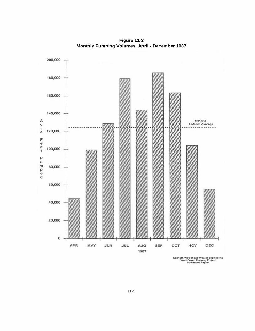
11-5
Figure 11-3Monthly Pumping Volumes, April - December 1987

11-6
Figure 11-4Monthly Pumping Volumes, January - August 1988

11-7
and returning only minor amounts to the lake.Comparing these values, it was concluded thatthe project’s actual operation was consistentwith anticipated design intent.
Gas Consumption - Monthly volumes ofnatural gas in million BTUs consumed by thethree 3,500 h.p. engines driving the verticalpumps during the first operational year werereported by Mountain Fuel Supply. Gasconsumption at the Pumping Plant varieddirectly with the volume of water pumped, butactual gas consumption was consistent withdesign specifications. Generally, with eachengine operating at maximum speed, the plantconsumed 43,000 million BTUs or 39,300cubic feet of natural gas per month. Atminimum speeds the plant consumed 30,500million BTUs or 28,000 cubic feet per month.Gas consumption generally improved withoperator adjustments and fine-tuned engines.
Evaporation - Evaporation rates for theWest Pond were estimated using climatologicaldata as a base in the systematic model andcomparing the predicted results with observedperformance of the West Pond. Figure 5compares normal (anticipated) evaporation ofthe West Pond with actual West Pondevaporation. Normal evaporation wascalculated using the translated normal (30-yeardata base) actual weather data as experiencedon the West Desert. Actual pond evaporationwas determined from actual freshwaterevaporation with allowances for salinity of thebrine. As the pond became more saline,evaporation rates reduced, and vice versa. Theactual evaporation rates entered in thecomputer model produced results which closelyemulated the actual observed performance ofthe West Pond.
Figure 5 shows that during the first ninemonths of the pumping operation in 1987,actual evaporation in the West Pond fell belownormal rates in all but two months. During thefirst eight months of 1988, evaporation rateswere approximately 10 percent above normal.
Figure 6 shows comparisons of
temperatures and monthly winds velocities, thetwo main components in the evaporationprocess. The charts compare actual vs. normalhigh temperatures and actual vs. average windspeeds.
The pumping project was evaporatingwater at a greater rate than anticipated due toclimatological factors, i.e., higher than normalwind velocities, and higher than normaltemperatures.
West Pond - The surface area and growthof the West Pond was tracked monthly usingsatellite imagery. The West Pond filled to itsoperation water surface level range after fivemonths (November 1987) of pumping. FromNovember 1987 through June 1988, the pondoperated at a water surface elevation range of4215.5 to 4216.5 (covering 255,000 to315,000 acres). Then the West Pond volumedeclined due to higher than normalevaporation rates and lower than anticipatedpumping rates.
A sampling program of the West Pondindicated the pond was well mixed and notnormally stratified with light and dense brines.Brine sampling also verified computer modelpredications of anticipated densities (salinity)throughout the pond.
As anticipated in the project design, fromApril through August of a given evaporationseason, evaporation generally exceeded inflowfrom the pumps. This created a net reductionin the pond’s surface elevation, area andvolume. The remainder of the year’s inflowfrom the pumps was greater than evaporation.The pond reacted as predicted by thespecialized evaporation model for this project.
Operational Range and Limitations ofthe West Desert Pumping Project - Theoperational range of the West Desert PumpingProject is directly linked to the water surfaceelevation of the Great Salt Lake. The PumpingPlant was designed to operate down to a lakewater surface elevation of 4205. Due tolimitations of the Intake Canal, the project nowcan only be operated to elevation 4207. The

11-8
Figure 11-5Monthly Evaporation in the West Pond, Actual vs. Normal

11-9
Figure 11-6Average High Temperatures, Actual vs. Normal

11-10
upper limit at which the Pumping Plant couldoperate is water surface elevation 4216.5. Atthis elevation, the gallery way in the PumpingPlant would be flooded.
Other constraints alter the way the projectoperates. Design features allowed pumpingdown to elevation 4205, but the U.S. Air Forcepermit limits pumping to around elevation4208. At a water surface elevation of about4217, water would naturally flow into theWest Pond area and submerge theNewfoundland Weir. The West Pond wouldthen be an extension of the Great Salt Lakeand pumping would be unnecessary.
Limitations of the pumping plant to act asan emergency flood control project aredependant upon the elevation of the Great SaltLake when pumps start up, the time of yearwhen pumping begins, the extent of thehydrologic cycle being experienced at the time,and the prediction of future hydrologic cycles.
Public Tours to HogupPossibly the best seat in town on July
20-22, 1987, was on a state-chartered tour busto the West Desert Pumping Project.
Tours of the project ordered by GovernorNorman H. Bangerter in response to keenpublic interest in seeing the huge pumps inaction and the river of water flowing from theGreat Salt Lake into the western desert werehosted by personnel from the Division ofWater Resources. Interest was spawned by theflooding, political controversy over spending$58 million for the project, and the highlypublicized cross-country truck journey of thehuge engines. And perhaps the mystery of thesite of the Pumping Plant was an attraction,because it is a part of the state rarely seen bythe general public.
Almost 1,500 people were shuttled freethe first day along the 10-mile Southern PacificTransportation Company causeway fromLakeside to the Pumping Plant site at HogupRidge. Many people waited up to two hoursduring a rainstorm that persisted most of the
first day for a seat on one of three buses. Twobuses were used the next day, and six on thelast day.
Permission to conduct the tours wasnegotiated with the U.S. Air Force and SPTC,because most of the area is military or railroadproperty.
The first half of the 20-mile round-tripbus ride featured a quick explanation ofcauseway construction and the flow of waterthrough the project, identification of lakeislands and other landmarks, and bits of lakehistory. Visitors to the plant were first shownphotos and drawings in the plant’s entrancearea about the project’s construction andoperation. They were then shown to thecontrol room where plant personnel explainedplant operation. Ear plugs were passed out andpeople were escorted on a walk-through of thenoisy engine room. Outside again, the tourtook in the pumping plant’s forebay, anexplanation of the natural gas pipeline andoperating system, and a trip across the plant’soutlet area with a view of the four-mile longcanal to the West Desert. The return bus tripwas all questions and answers.
A second round of tours was held August19-21. Visitors were charged $2 a person forthe tour, and reservations were requested. Finaltours, on a weekend, were held September 12-13. Reservations and a $2 fee were alsorequired for the Saturday and Sunday tours.
An estimated 4,700 people saw the pumpsduring the three tour sessions. In addition,numerous tours were conducted during theproject’s pumping period for students onschool district buses.
Response to the tours was gratifying to thegovernor and division engineers and managers.Typical comments were:
“Just reading about the project, I didn’trealize how big this was. I thought it was awaste of money. Now that I’ve seen it, I thinkit’s a worthwhile investment.”
“I’ve worked on the railroads and thoseengines are big, but they are nothing compared

11-11
to the turbines. These things dwarf them.”“It was really neat,” exclaimed one eight-
year old. “It’s weird when you get in therebecause the screens make it feel like you’regoing to fall through the floor.”
State officials believed response to thetours was overwhelmingly positive.
Early ProblemsProject engineers anticipated problems
with the pumping project once it got underway,because it had been constructed and put intooperation so quickly. Happily, only threeproblems briefly shut down some or all of thepumping operation.
The first was a burned out lower bearingin the large pump of Unit 1 during the firstweek after startup. The pumping project’ssophisticated sensor system detected theproblem before major damage occurred. Thedamaged bearing was quickly and easilyreplaced. The bearing cost an estimated$50,000, but it was covered by amanufacturer’s warranty.
Nearly six months into the full pumpingoperation, a cooling water pump failed,shutting down the pumping operation forseveral days. The lake brine apparentlycorroded the pump’s shaft near a coupler andthe pump erupted from its base. The coolingwater pump served the three pumping units,distributing lake water to engine heat
exchangers and to cool engine oil andturbochargers.
It was determined the coupler and shaftwere made from different grades of stainlesssteel, and the heavy brine caused crevicecorrosion on the lower grade 1.5-inch shaft. Areplacement cooling water pump with a 316stainless steel shaft and coupler was installed.
The third problem was a phenomenoncalled Glauber salt, or mirabilite, that thinlycoated the pumps’ impellers and section bellsduring the winter and shut down the pumpingproject from December 14, 1987, to February2, 1988, and at approximately the same time in1988-89. The coating wasn’t uniform andcaused almost imperceptible vibrations thatwere caught by sensors in the Pumping Plant.The turning impeller was a natural attractor.
Officials at Great Salt Lake MineralsCompany, who had encountered Glauber’s saltduring their operations, explained theGlauber’s salt is a colorless crystalline sulfate ofsodium that apparently can form on objects inthe Great Salt Lake when the lake brine is 28to 30 degrees, and can occur anytime betweenmid-September to February. Although diversremoved most of the coating from the pumpimpellers with hot water shortly after the firstoccurrence, project managers determinednothing could be done to prevent theoccurrence of the Glauber salt. -

11-12
Fact Sheet: West Desert Pumping Project
Operating facts:(April 10, 1987 to August 31, 1988)Volume pumped: 1,767,995 acre-feetVolume evaporated: 1,350,000Volume returned to lake: negligibleEffect on lake: lowered 14.5 inches
Pumping RateOne pump: 450,000 gpm (1,000 cfs)Two pumps: 900,000 gpm (2,000 cfs)Three pumps: 1,350,000 gpm (3,000 cfs)
PumpsType: Ingersoll-Rand vertical axis mixed flowImpeller: 3 blades, 119 in. dia., 12,000 lbs.Shaft: 10.7 in. dia., 45.5 ft. long, 18,750 lbs.
Gear DriveWeight: 36,000 lbs.Speed ratio: 22.37Manufacturer: Brad Foote Gear Inc., Cicero, IL
EnginesDimensions: 27 ft. 11 in. long, 11 ft. 10 in. wide, 17 ft. 10 in. high, 16-cylinder 3,500 hp rating, 16.25 in bore, 18 in. strokeOperating speed: 330 rpmWeight: engine and skid - 162,800 lbs.Manufacturer: Dresser-Rand, Painted Post, NYA contract for pumps, gear drives and engines was awarded to Ingersoll-Rand, Painted Post, NY, for $7,829,378.68
Pumping PlantDimension: 110 ft. long, 55 ft. wide, 85 ft. highEngine deck elevation: 4230Sump bottom elevation: 4175Construction: Steel and reinforced concrete (13,000 cu. yds. of reinforced concrete)Contractor: Layton Construction Co., Salt Lake City, UTEngineer: Eckhoff, Watson and Preator Engineering and Morrison-Knudsen Engineers, Inc.Original bid: $7,891,378.68Final cost: $10,387,560
Outlet CanalLength: 4.1 miles
Bottom elevation: varies between 4210-4207Bottom width: varies between 75-100 ft.Top width: varies between 120-150 ft.Operating depth: minimum 10-11 ft.Slope of canal: avg. .18 ft. Per 1,000 yds.Material dredged: 640,000 cu. yds.Contractors: Southern Pacific Transportation Co./ Lost Dutchman, Inc.Engineer: Eckhoff, Watson and Preator Engineering
Access RoadLength: 10 milesHeight: 13 ft.Width: 18.5 ft.Volume of fill: 1.2 million cu. yds.,Lakeside to HogupBridges: 4 (3-150 ft. long, 1-180 ft. long)Contractor: Southern Pacific Transportation Co.Engineer: Eckhoff, Watson and Preator EngineeringSPTC’s contract included excavation of thepumping plant foundation, excavation of the outlet canal, construction of four bridges,reconstruction of the damaged 10-milecauseway, and raising 25 miles of railroad trackfor a total of $22,980,000.
Bonneville Dike Length: 24.4 milesHeight: 3-6 ft.Volume of fill: 486.500 cu. yds.Rip rap: 152,00 cu. yds.Contractor: W. W. Clyde Construction, Springville, UTContract: $3,872,845
Newfoundland DikeLength: 8.1 milesHeight: 3-7 ft.Volume of fill: 249,000 cu. yds.Rip rap: 85,000 cu. yds.Control weir: 1,000 ft. longContractor: Herm Hughes and Sons, Bountiful, UTEngineer: Bingham EngineeringContract: $2,464,030

12-1
Chapter 12
Shutdown of the West Desert Pumping
Project
The Shutdown Process 1 Pumping Plant Shutdown 1
Reactivating the Pumping Plant 3
The Shutdown ProcessUtah’s Great Salt Lake West Desert Pumping
Project was shut down June 30, 1989, afteroperating successfully for more than two years. Along-term, or “mothball,” shutdown procedure forthe Pumping Plant proposed by Dresser-Rand wasaccepted by the state. After meeting withrepresentatives of equipment suppliers, i.e. Dresser-Rand Engine-Process Compressor Division,Cummins Northwest, Ingersoll-Rand Pump Group,etc., the Dresser-Rand Services Divisionimplemented the preservation steps. Extensivepreservation methods requires monthly inspectionsby qualified individuals and periodic internalinspections of preserved equipment.
The shutdown process took about eight weeksand cost approximately $200,000, which was withinthe project’s budget. The process included securingthe Pumping Plant; dismantling, preserving andstoring tools, systems and control devices; andinspection and maintenance of the project site.
The following are some of the shutdownprocedures for some of the major components at thePumping Plant site.
Pumping Plant ShutdownEngines and Pumps - Because the Pumping
Plant was to remain in place as insurance against future flooding around the Great Salt Lake,disassembly or removal of the three large enginesand pumps were not options.
Control Panel - The circuitries of the Dynalcoscanners, Moore SLD controllers, and Allen-BradleyPLC-4 were removed and stored in the plant. Openports of the pneumatic safety shutdown and enddevices were plugged, and the pneumatic circuitry ofthe engine and control panel are maintained under aslight positive pressure charge of nitrogen gas. Thepanel was covered with plastic to prevent dustcontamination and volatile corrosion inhibitor (VCI)paper was placed inside the engine-mounted wiringjunction box.
Frame and Running Gear- The crankcase,valve train and accessory drive components of theengines were protected through a combination ofprocedures. During the last 30 to 60 minutes of each

12-2
engine’s operation, a three-phase rust inhibitor wasadded to the engine oil. After engines cooled, valvecovers, crankcase doors and other access covers wereremoved and a solvent-based rust inhibitor wassprayed on all engine internal components. VCIcapsules were placed in various locations inside eachengine to augment the rust inhibitor protection. Fuelgas injection valves were removed and solvent-basedinhibitor was sprayed into power cylinders, thenreplaced against original gaskets. Protective oil waspoured into push rod tubes, and hydraulic lifterswere removed, dipped in protective oil, bagged andtagged for location, and placed in the rocker armarea of the cylinder heads. The valve stem lubricatorreservoir, pumps and tubing were filled withprotective oil. In addition, electric motors for thevalve stem lubricator and auxiliary oil pump werewrapped and covered with plastic to prevent dustcontamination. Crankcase breather piping was alsosealed with plastic.
Lube Oil Piping- The engine oil/rust inhibitormix was left in the engine oil sump and piping. Areconfigured pneumatic auxiliary oil pump isperiodically operated with the small air compressorto recirculate the engine oil/inhibitor mix throughthe gear reducer.
Drive Line and Brad-Foote GearReducer - Exposed, unpainted portions of the quillshaft were coated with protectorant, and quill shaftbearings (pedestal bearings) were drained andrefilled with protective oil. During the last 30 to 60minutes of the unit’s operation, a three-phase rustinhibitor was added to the gear oil to be carried toall moving parts. Internal components were sprayedwith solvent-based rust inhibitor. The gear oil/rustinhibitor mixture is to be circulated periodically. AHASKEL pneumatic pump is used for this task. Thebrine side of the heat exchanger was washed withfresh water and allowed to dry.
Ingersoll-Rand Pumps - The greasedistributing tubes of the Farval grease system weredisconnected from the measuring valves and capped,as were the inlet ports on the valve blocks. The maingrease supply lines were also disconnected at theunit’s reversing valve. In addition, the electric motorwas wrapped in paper and plastic, the reversing valve
and grease pump were purged of grease and sealed,and the pump drive gearbox was filled withprotective oil. The grease reservoir and bulk greasetransfer pump were cleaned and sealed, the bulkgrease pump motor lubricator was filled withprotective oil, and the microprocessor circuitry wasremoved and stored in a controlled environment.VCI paper was placed inside the circuit boxes.
Brine Cooling Water System - The brinepump motors were removed and stored. Brine pumprotating elements and casings were removed, flushedwith fresh water, and stored inside the engine room.Piping also was flushed.
Fuel Gas Supply Pipeline - The natural gasfuel supply remains connected to the engine room. Natural gas is used to power a small generator in thePumping Plant. Isolated fuel headers on the threeengines are under positive nitrogen gas pressure.
Air Compressors and Piping - Motors on theair compressors were wrapped in paper and plastic,and the entire piping circuit, including air receivers,was isolated from the air compressors. Rust inhibitorwas added to the air compressors’ crankcase oil. Airintake filters were removed and inlets were sealed,and cylinders and valve decks were sprayed withpreservative. The piping circuit for instrument airreceived similar treatment.
Siphon Break Valves - Rubber on the butterflyvalve was cleaned and coated with preservative. Theactuator assembly was removed and stored in theengine room. A VCI plug was fitted to each end ofthe pneumatic cylinder, and protective oil was addedto the linkage box. Handwheel threads were wrappedwith paper and plastic. The siphon break was sealedwith reinforced plastic.
Cummins Gas Engines - VCI paper was placedinside the housings for the monitor panel and timingshift unit. Protection for the crankcase, valve trainand accessory drive units of the frame and runninggear required a combination of procedures. Duringthe last 30 to 60 minutes that each engine operated,three-phase rust inhibitor was added to the engineoil. Valve covers and access covers were thenremoved and the engine’s internal components weresprayed with solvent-based rust inhibitor. Crankcasebreather piping was sealed at the engine. An actuator

12-3
was removed and stored. Turbochargers, however,were left on the engines. The Altronic III ignitionunits, ignition coils and high and low tension wiringwere removed and stored in a controlledenvironment. Exhaust piping outlets and air filterinlets were sealed with reinforced plastic and variousother elements were sealed. The entire coolingsystem has been maintained under positive nitrogenpressure.
Pumping Plant Building - The pump/motorfor the building’s potable water system was removedfrom the underground storage tank and stored in theservice building. The storage tank was drained, tankopenings were sealed, pipes were disconnected, andthe tank was filled with nitrogen gas. The indoorpressurized water tank and Pennwalt hypo-chlorinator was disconnected from the piping systemand filled with nitrogen gas. All water pipes weredrained and blown out with compressed air. Thewastewater system was sealed and the septic tankwas pumped. Roof vents for the wastewater systemremain open. Other elements of the building thatwere sealed include the HVAC system, safety andemergency lighting systems, control room electricalenclosures and doors, windows, and ventilatinggrilles. Tools and other equipment were eitherboxed for storage in the building or removed to otherstorage areas.
The Pumping Plant is inspected monthly bystaff of the Division of Water Resources and periodicevaluations are made on the condition of engines,pumps and other equipment at the Pumping Plantsite.
Reactivating the Pumping PlantIn the event the West Desert Pumping Project
is reactivated, the startup process could take between8-12 weeks to accomplish. In addition to reversingthe shutdown procedure, many pieces of equipmentwould need to be partially or completely dismantledand inspected. A percentage of this equipment wouldlikely require replacement because some of thecontrol electronics may be outdated; it would bemore efficient to replace it with current technology.
Reactivating the Pumping Plant would requirestartup services to be contracted with Dresser-Rand
or another qualified mechanical services company.Estimated cost of reactivating the Pumping Plant is$250,000 to $300,000. The Pumping Plant wouldnot be reactivated unless it were operated for one ormore years. The State Legislature would also need toappropriate a yearly operating budget ofapproximately $2 million. -