CSNB374: Microprocessor Systems Chapter 1: Introduction to Microprocessor.
Upload
anastasia-lesterCategory
view
236download
0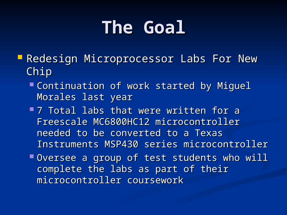
The GoalThe Goal
Redesign Microprocessor Labs For New Redesign Microprocessor Labs For New ChipChip Continuation of work started by Miguel Continuation of work started by Miguel
Morales last yearMorales last year 7 Total labs that were written for a Freescale 7 Total labs that were written for a Freescale
MC6800HC12 microcontroller needed to be MC6800HC12 microcontroller needed to be converted to a Texas Instruments MSP430 converted to a Texas Instruments MSP430 series microcontrollerseries microcontroller
Oversee a group of test students who will Oversee a group of test students who will complete the labs as part of their complete the labs as part of their microcontroller courseworkmicrocontroller coursework
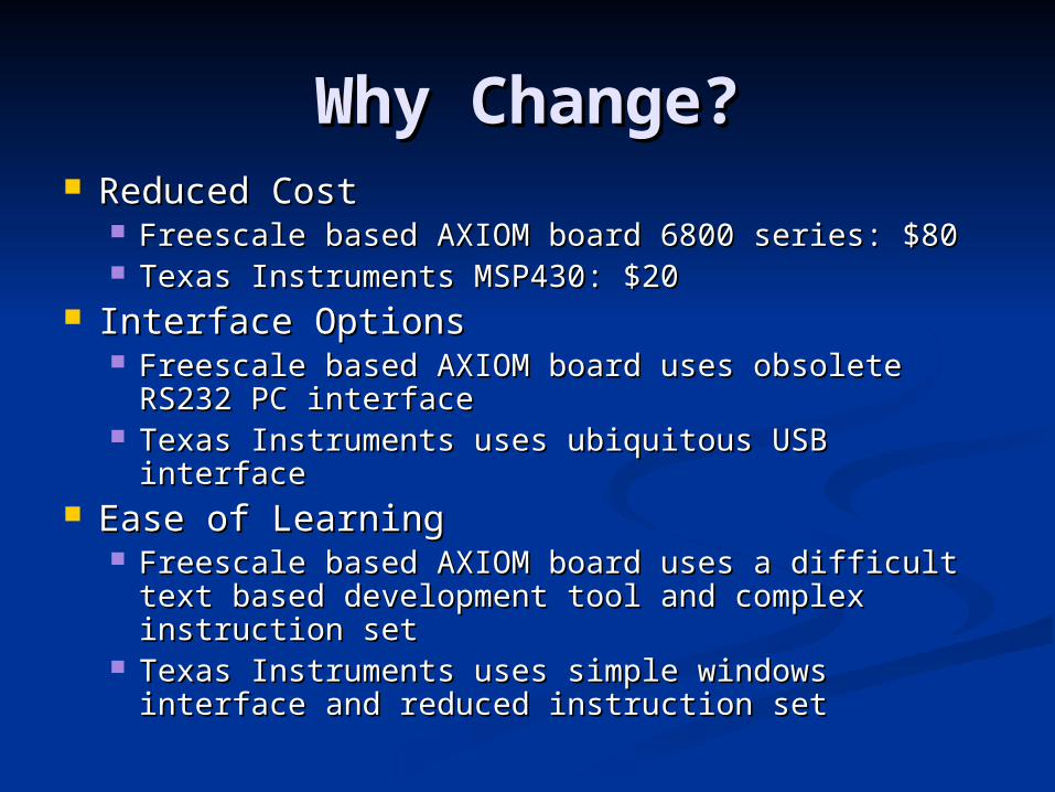
Why Change?Why Change? Reduced CostReduced Cost
Freescale based AXIOM board 6800 series: $80Freescale based AXIOM board 6800 series: $80 Texas Instruments MSP430: $20Texas Instruments MSP430: $20
Interface OptionsInterface Options Freescale based AXIOM board uses obsolete Freescale based AXIOM board uses obsolete
RS232 PC interfaceRS232 PC interface Texas Instruments uses ubiquitous USB interfaceTexas Instruments uses ubiquitous USB interface
Ease of LearningEase of Learning Freescale based AXIOM board uses a difficult Freescale based AXIOM board uses a difficult
text based development tool and complex text based development tool and complex instruction setinstruction set
Texas Instruments uses simple windows interface Texas Instruments uses simple windows interface and reduced instruction setand reduced instruction set
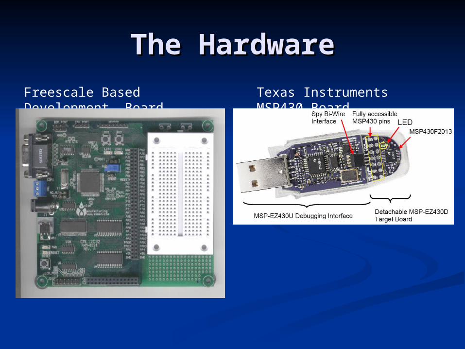
The HardwareThe Hardware
Freescale Based Development Board
Texas Instruments MSP430 Board
The Next StepThe Next Step
Design something using what we Design something using what we learnedlearned Leverage the benefits of the TI MSP430Leverage the benefits of the TI MSP430
Low CostLow Cost Low PowerLow Power Easy DevelopmentEasy Development
Apply the technology from our labs to build Apply the technology from our labs to build something usefulsomething useful
Digital Input / OutputDigital Input / Output Edge DetectionEdge Detection Timing and CountersTiming and Counters
What Is WWVBWhat Is WWVB Radio station broadcasting official Radio station broadcasting official
government timegovernment time Broadcast antenna located north of Fort Broadcast antenna located north of Fort
Collins Colorado (Figure 1)Collins Colorado (Figure 1) 60kHz Carrier Wave60kHz Carrier Wave 50kW Total Transmit Power50kW Total Transmit Power
Set to the NIST-F1 atomic clock in BoulderSet to the NIST-F1 atomic clock in Boulder Accurate to 1 second over 60 million yearsAccurate to 1 second over 60 million years Error rate less then 0.1 nanoseconds / dayError rate less then 0.1 nanoseconds / day
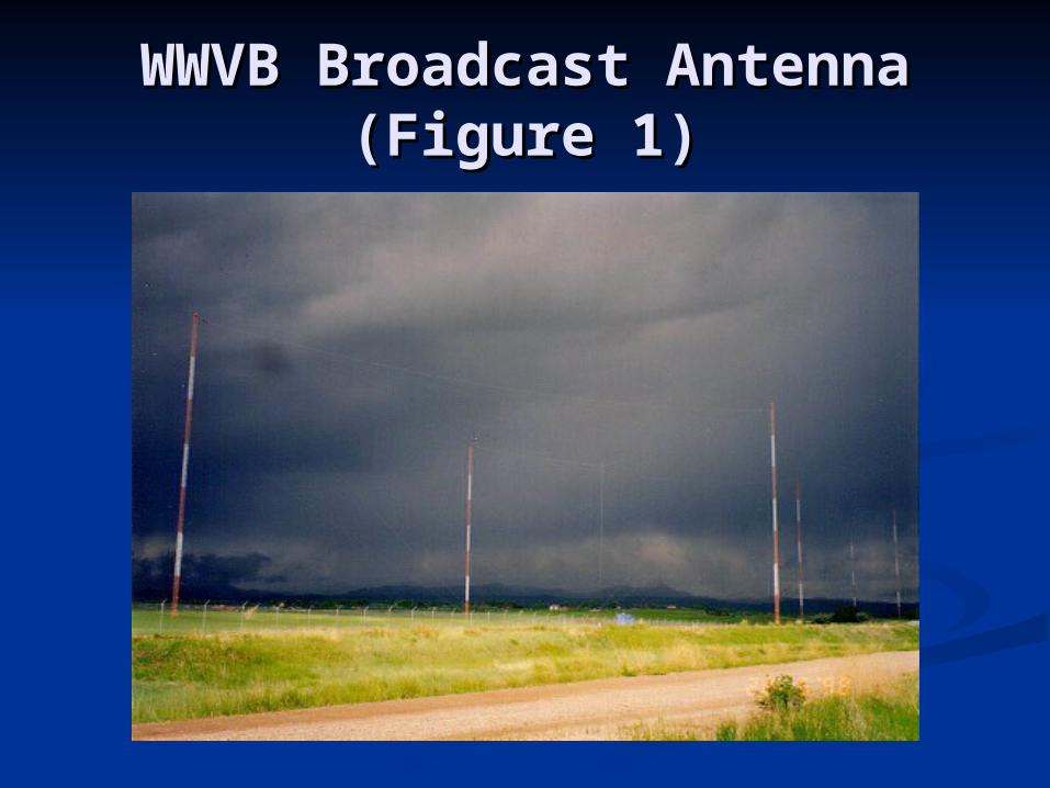
WWVB Broadcast AntennaWWVB Broadcast Antenna(Figure 1)(Figure 1)
Receiver First StageReceiver First Stage Receiver Comprised of antenna and 4 stage Receiver Comprised of antenna and 4 stage
amplifier (Figure 2)amplifier (Figure 2) Signal ReceptionSignal Reception
The 60kHz carrier wave is picked up using a The 60kHz carrier wave is picked up using a loopstick antenna (Figure 3)loopstick antenna (Figure 3)
Ferrite Core Inductor in parallel with a Ferrite Core Inductor in parallel with a capacitorcapacitor
Received signal strength is too small to measureReceived signal strength is too small to measure First Stage AmplifierFirst Stage Amplifier
Uses a JFET (High Input Impedance) LF351 Uses a JFET (High Input Impedance) LF351 Operational AmplifierOperational Amplifier
First stage output strength roughly 2mVpp First stage output strength roughly 2mVpp
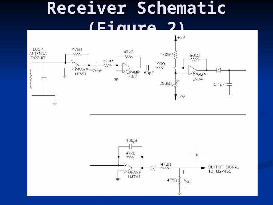
Receiver Schematic Receiver Schematic (Figure 2)(Figure 2)
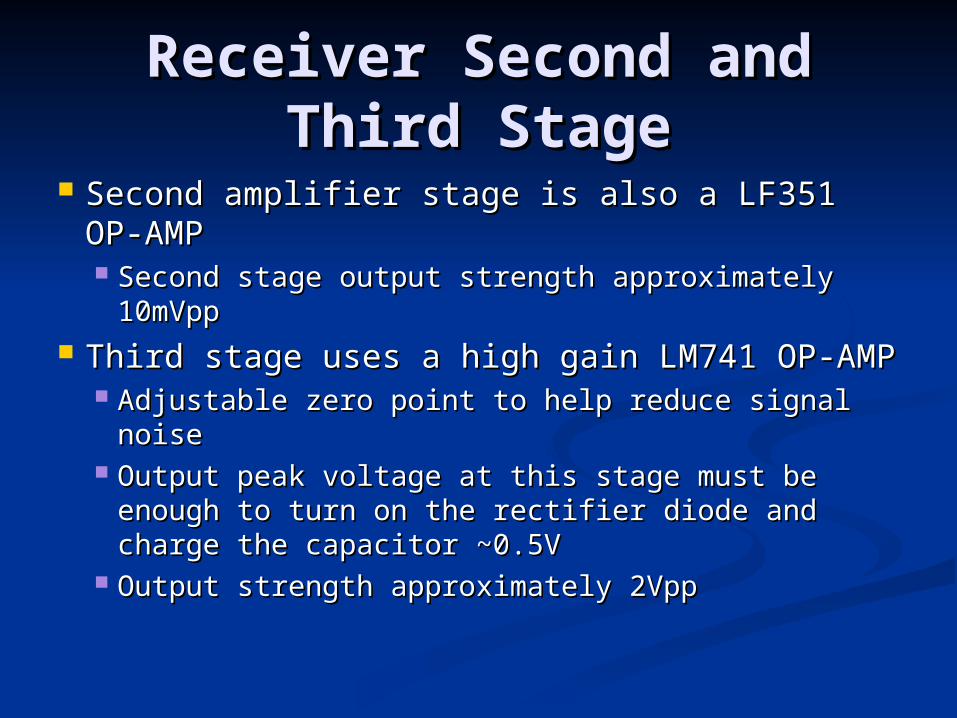
Receiver Second and Receiver Second and Third StageThird Stage
Second amplifier stage is also a LF351 OP-Second amplifier stage is also a LF351 OP-AMPAMP Second stage output strength approximately Second stage output strength approximately
10mVpp10mVpp Third stage uses a high gain LM741 OP-AMPThird stage uses a high gain LM741 OP-AMP
Adjustable zero point to help reduce signal noiseAdjustable zero point to help reduce signal noise Output peak voltage at this stage must be enough Output peak voltage at this stage must be enough
to turn on the rectifier diode and charge the to turn on the rectifier diode and charge the capacitor ~0.5Vcapacitor ~0.5V
Output strength approximately 2VppOutput strength approximately 2Vpp
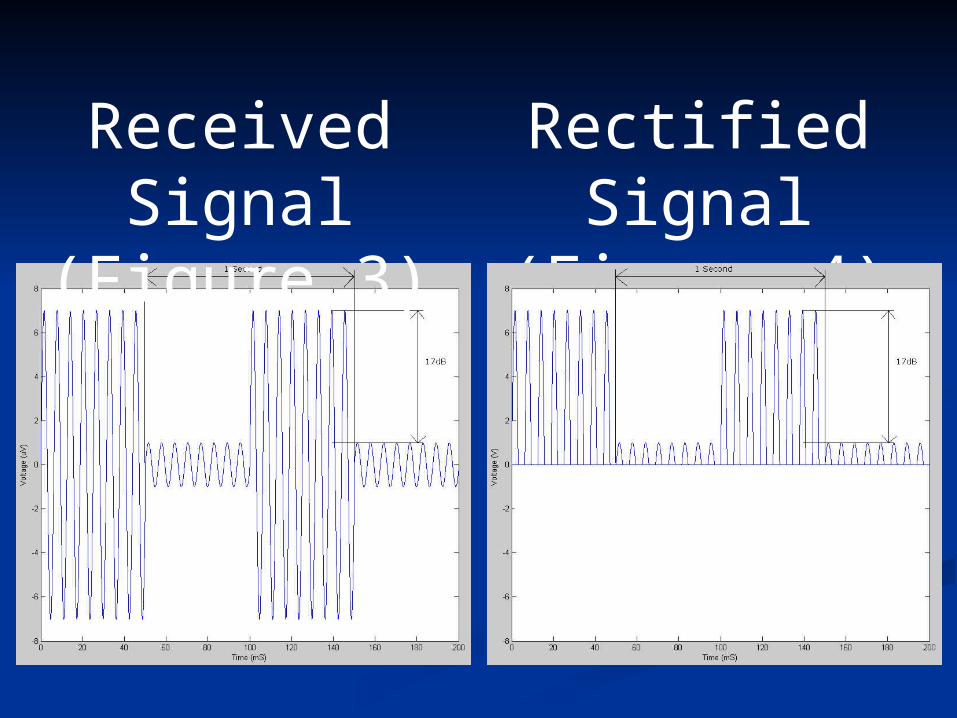
Received Signal
(Figure 3)
Rectified Signal
(Figure 4)
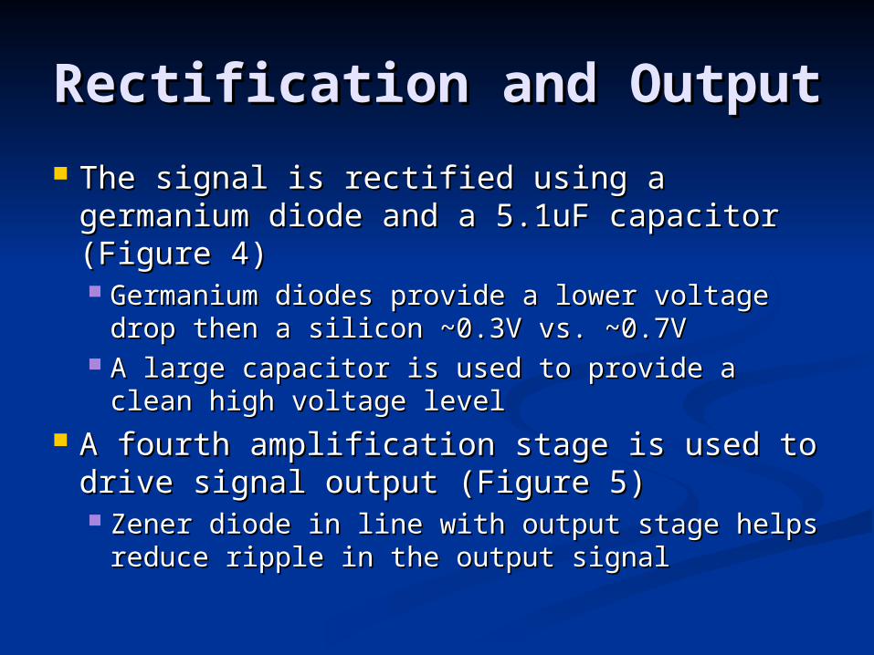
Rectification and OutputRectification and Output
The signal is rectified using a germanium The signal is rectified using a germanium diode and a 5.1uF capacitor (Figure 4)diode and a 5.1uF capacitor (Figure 4) Germanium diodes provide a lower voltage Germanium diodes provide a lower voltage
drop then a silicon ~0.3V vs. ~0.7Vdrop then a silicon ~0.3V vs. ~0.7V A large capacitor is used to provide a clean A large capacitor is used to provide a clean
high voltage levelhigh voltage level A fourth amplification stage is used to A fourth amplification stage is used to
drive signal output (Figure 5)drive signal output (Figure 5) Zener diode in line with output stage helps Zener diode in line with output stage helps
reduce ripple in the output signal reduce ripple in the output signal
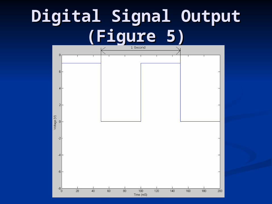
Digital Signal OutputDigital Signal Output(Figure 5)(Figure 5)
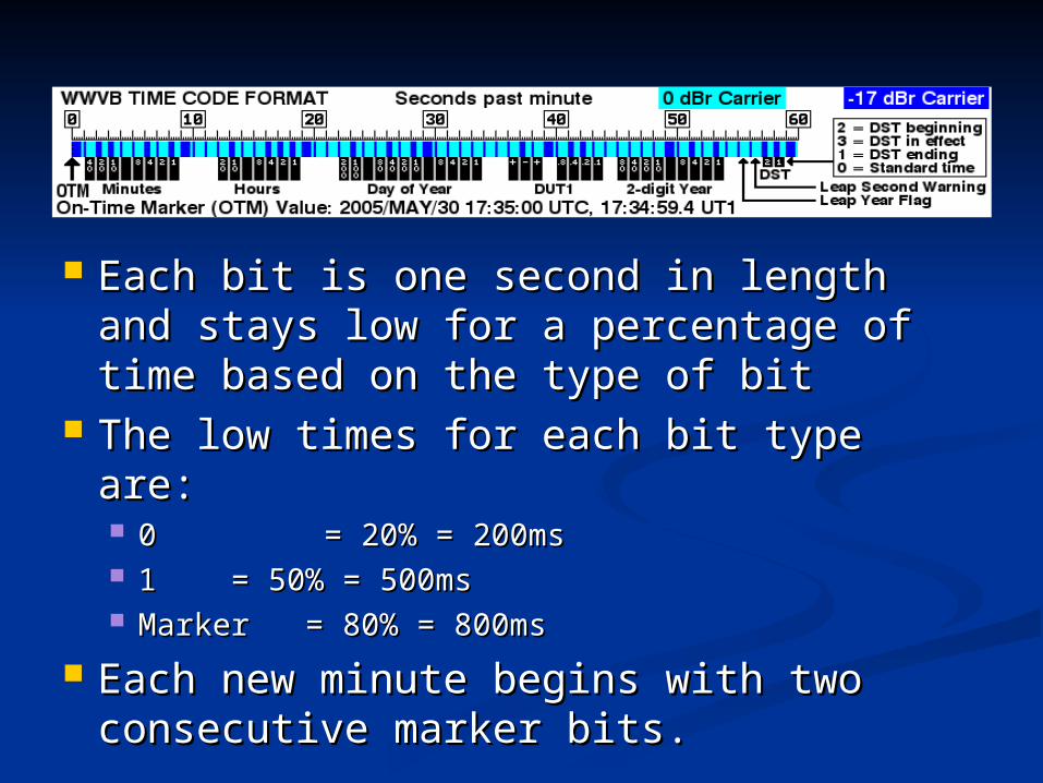
Each bit is one second in length and Each bit is one second in length and stays low for a percentage of time stays low for a percentage of time based on the type of bitbased on the type of bit
The low times for each bit type are:The low times for each bit type are: 00 = 20% = 200ms= 20% = 200ms 1 1 = 50% = 500ms= 50% = 500ms Marker = 80% = 800msMarker = 80% = 800ms
Each new minute begins with two Each new minute begins with two consecutive marker bits.consecutive marker bits.
MSP430 Decoder and MSP430 Decoder and ClockClock
Clock functionsClock functions The MSP430 uses a 16MHz clock with its The MSP430 uses a 16MHz clock with its
timer system to create an 8ms count. This timer system to create an 8ms count. This count is used to measure one second (125 count is used to measure one second (125 counts)counts)
Each second the display time is updatedEach second the display time is updated DecodingDecoding
Interrupts are used to detect rising and Interrupts are used to detect rising and falling edgesfalling edges
Time between falling and rising is Time between falling and rising is measured to determine the bit typemeasured to determine the bit type
Time is updated after a full minute signal Time is updated after a full minute signal has been received without any errorshas been received without any errors
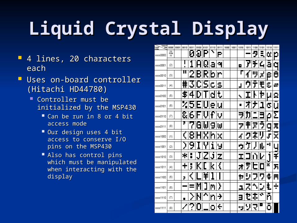
Liquid Crystal DisplayLiquid Crystal Display 4 lines, 20 characters 4 lines, 20 characters
eacheach Uses on-board controller Uses on-board controller
(Hitachi HD44780)(Hitachi HD44780) Controller must be Controller must be
initialized by the MSP430initialized by the MSP430 Can be run in 8 or 4 bit Can be run in 8 or 4 bit
access modeaccess mode Our design uses 4 bit Our design uses 4 bit
access to conserve I/O pins access to conserve I/O pins on the MSP430on the MSP430
Also has control pins which Also has control pins which must be manipulated when must be manipulated when interacting with the interacting with the displaydisplay
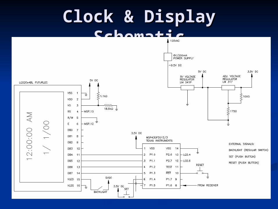
Clock & Display Clock & Display SchematicSchematic