Minimizing Disputes and Maximizing Profits: Five Balancing ...

The Future Combat System: Minimizing Risk While Maximizing Capability
USAWC Strategy Research Project
by
Colonel Brian R. Zahn, USA
May 2000
Working Paper 00 – 2 The views expressed in this academic research paper are those of the author and do not necessarily reflect the official policy or position of the U.S. Government, the Department of Defense, or any of its agencies.

2
ABSTRACT
AUTHOR: Colonel Brian R. Zahn TITLE: The Future Combat System: Minimizing Risk While Maximizing Capability FORMAT: Strategy Research Project DATE: 24 April 2000 PAGES: 45 CLASSIFICATION: Unclassified This paper examines some of the technological candidates that are potential enablers of the Army Transformation to
the future Objective Force. The paper highlights the technological risk associated with the Future Combat System
program and offers an alternative acquisition strategy to minimize risk while maximizing potential capability. The
paper examines lethality technologies such as the electromagnetic gun, electrothermal chemical gun, missile-in-a-
box, and compact kinetic energy missile. Survivability candidates include passive armors, reactive armors, and
active protection systems. The paper also examines the wheeled versus tracked debate. The paper concludes by
recommending some of the technologies for further development under a parallel acquisition strategy.
3
TABLE OF CONTENTS
ABSTRACT.......................................................................................................................................................................III
PREFACE ........................................................................................................................................................................ VII
LIST OF ILLUSTRATIONS...........................................................................................................................................IX
LIST OF TABLES ............................................................................................................................................................XI
METHODOLOGY AND SCOPE.....................................................................................................................................2
THE RELEVANCE DEBATE..........................................................................................................................................4
THE THREAT.....................................................................................................................................................................6
USER REQUIREMENTS..................................................................................................................................................7
DESIGN TRADEOFFS………………………………………………………………………………………………8
LETHALITY .......................................................................................................................................................................9
CHEMICAL ENERGY WEAPONS .....................................................................................................................10
ENHANCED LETHALITY WITH KINETIC ENERGY.....................................................................................12
ELECTROMAGNETIC GUN ..............................................................................................................................13
ELECTROTHERMAL CHEMICAL GUN..........................................................................................................16
SURVIVABILITY.............................................................................................................................................................17
PASSIVE ARMOR................................................................................................................................................22
REACTIVE ARMOR………..………………………………………………………………..…………………….....23
ELECTROMAGNETIC ARMOR…………………………………….……………………………………………….24
ACTIVE PROTECTION SYSTEMS…………………………………………………... ……………………………26
MOBILITY…………………………………………………………………………………………………………...27
RECOMMENDATIONS……………………………………………………………………………………………30
CONCLUSION……………………………………………………………………………………………………...32
ABREVIATIONS AND ACRONYMS……………………………………………………………………………..35
ENDNOTES…………………………………………………..…………………………………………………………………37
BIBLIOGRAPHY.............................................................................................................................................................43

4
PREFACE
I am sincerely grateful to the staffs of the Security Studies Program at the Massachusetts Institute of Technology and the Army War College at Carlisle, Pennsylvania. The Senior Service College Fellowship Program and the support of these two organizations provided an outstanding opportunity for individual research on a topic of personal interest. In particular, I would like to thank Dr. Owen Cote, Associate Director of the MIT Security Studies Program, for his invaluable assistance, advice, and encouragement during this project. I would also like to thank Colonel Joe Cerami, Chairman, Department of National Security and Strategy at the Army War College for his advice on this paper and his mentorship throughout the academic year.

5
LIST OF ILLUSTRATIONS FIGURE 1. US ARMY TANK EVOLUTION.......................................................................................................................... 4
FIGURE 2. FCS PROGRAM GOALS ..................................................................................................................................... 7
FIGURE 3. FCS FUNCTIONS ................................................................................................................................................ 8
FIGURE 4. SHAPED CHARGE TECHNOLOGY ..................................................................................................................11
FIGURE 5. MISSILE IN A BOX............................................................................................................................................12
FIGURE 6. CONCEPT SKETCH - ELECTROMAGNETIC GUN...........................................................................................13
FIGURE 7. COMPULSATOR POWER SUPPLY...................................................................................................................15
FIGURE 8. 20-TON VEHICLE WEIGHT DISTRUBUTION TRADEOFFS............................................................................19
FIGURE 9. SURVIVABILITY STRATEGY...........................................................................................................................21
FIGURE 10. REACTIVE ARMOR TECHNOLOGY ..............................................................................................................23
FIGURE 11. ELECTROMAGNETIC ARMOR CONCEPT.....................................................................................................25
FIGURE 12. TYPICAL ACTIVE PROTECTION SYSTEM....................................................................................................26
FIGURE 13. GROUND PRESSURE VS. NO-GO TERRAIN..................................................................................................28

6
LIST OF TABLES
TABLE 1 COMPONENT WEIGHTS ...................................................................................................................................17
TABLE 2. SURVIVABILITY APPROACH FOR AN ADVANCED 20-TON VEHCILE CONCEPT......................................22

7
“SNAFU, that’s it!” said Senator John Warner (R-Va.), pointing to the Army’s new Chief of Staff,
GEN Eric Shinseki, during the Joint Chief’s testimony before the Senate Armed Services Committee in
late 1999. The Committee Chairman used the acronym to describe the Army’s performance during the
78-day campaign in Kosovo - strong words given the vulgar character of the acronym and the fact that it
was used by a long-time friend and supporter of the military. World War II soldiers used the acronym,
meaning “Situation Normal, All Fouled Up” (a benign translation), to describe a disorganized environment
that plagued an Army manned largely by conscripts and commanded by inexperienced young officers.
Warner’s application of the term to a modern, professional Army boasting recent successes in Iraq, Haiti,
and Bosnia represented a profound indictment of the Army’s ability to adapt to a new and dynamic post-
Cold War environment. Despite these accomplishments, the Army had developed a reputation as the
“can’t do force” among members of Congress1 and, while there were certainly extenuating circumstances,
the Army clearly stood on the sidelines during the Kosovo conflict. Indeed, General Shinseki had his
work cut out for him.
Fortunately, the visionary Chief had already recognized the need for change. Only weeks earlier,
the general announced a plan intended to transform the Army into a lighter, more agile force - suggesting
its heavy forces are too heavy and its light forces are not lethal enough. He unveiled his plan before
Army and industry leaders at the October 1999 Annual Meeting of the Association of the United States
Army (AUSA) in Washington, D.C.. The plan posits a fundamental transformation; from an Army
organized around heavy armored divisions to one that will increasingly rely on medium-weight units that
are equally lethal but more readily deployable. The first step in the process is the ongoing Medium
Weight Brigade concept that involves equipping two light brigades with light armored vehicles - creating a
highly lethal and rapidly deployable force. The transition will culminate in 10-12 years with the fielding of
the “Objective Force” that has been the recent focus of the Army’s science and technology efforts. This
paper focuses on the technologies associated with equipping an Objective Force that must be capable of
defeating asymmetric and traditional opponents anywhere on the spectrum of operations, from
humanitarian assistance to high-intensity combat, and rapid transition between mission requirements
without loss of momentum.2
While many agree that change is warranted, the plan includes revolutionary components, such as
the conversion to an all-wheeled force that are certain to produce friction in the tradition-bound Army.
GEN Shinseki prepped the AUSA crowd with the following: “Can we, in time, go to an all-wheel vehicle
fleet, where even the follow-on to today’s armored vehicles can come in at 50 percent to 70 percent less
tonnage? I think the answer is yes, and we’re going to ask the question and then go where the answers
are.”3 While there may be answers out there, many come with a significant caveat - the technical risk that
must be addressed before such a force is possible. I believe these risks, while formidable, can be
managed by employing a practical acquisition strategy that focuses on parallel development of multiple,
competing technologies.

8
Methodology and Scope
The Army wants leap-ahead results and not incremental improvements - and it wants them soon.
Because of the ambitious timeline and technical uncertainties, the Army’s plan is to rapidly identify the
most promising technologies and then invest significant resources into them in hopes of obtaining leap-
ahead results. The approach seems rational in that it promises to provide decision makers the requisite
knowledge on each of the technologies that will enable timely decisions, focused developmental efforts,
and reduced propensity for cost increases and schedule slippage. Unfortunately, many experts doubt
whether industry will be able to deliver these leap-ahead capabilities within the stated timelines.
Consequently, instead of asking which technologies to invest in, the more relevant question may be which
acquisition strategy will best manage uncertainty while maximizing the benefits of technological
innovation.
To address that question, this paper first attempts to validate the need by examining the
background of the issue, the threat, and Army requirements. Next it presents design tradeoffs associated
with armored vehicles and examines some of the key technologies that promise significant advances in
lethality, survivability, and mobility. The purpose here is to illustrate the high degree of programmatic
technical risk in an effort to lay the groundwork for an alternative acquisition strategy.
The Army’s plan is to search for technologies that will provide answers, within about 3 years, that
they will use to design the Objective Force 8-10 years down the road.4 That is, the Army will give industry
until 2003 to optimize their top contenders and present them to selection boards. The Army will evaluate
the candidates against established selection criteria and then select the best and most promising for
advanced development and production. I posit an alternative acquisition approach - one that delays the
production decision and allocates comparatively more resources to basic research over time rather than
risking premature selection of chancy technologies and proceeding with full scale production. The belief
is that this strategy will maximize technological benefit through competition over a longer period of time.
Furthermore, since production is delayed until the need is demonstrated, there will be less risk of
premature obsolescence. The main drawback of this strategy is the risk of not having a fielded system
when needed in the event of a sudden escalation of the threat, but this concern is rendered nearly
immaterial by virtue of the U.S.’s unmatched conventional ground warfare capability. It does however,
underscore the requirement for significant conventional heavy forces.
The issue draws attention to one certainty - the presence of tremendous uncertainty - a condition
that nearly always accompanies technological innovation. These uncertainties are nearly impossible to
prevent but they can be managed during the acquisition process. Dr. Harvey Sapolsky5 presents an
argument by James D. Thompson that there are essentially three types of uncertainly associated with
innovation: 1) Generalized – the means-ends issue of which business to be in. 2) Contingency – the
need to have other organizations cooperate to succeed. 3) Linking Internal Units – the problem of making
an efficient production process within the organization.6 Of the three, it appears in this case that the most
complicated uncertainly will be the second type – the need to obtain cooperation both within and external

9
to the Army. Intuitively, one would expect technological risk to be the most significant dynamic in this
case, but overcoming technological risk is relatively easy when compared to gaining widespread political
support within a large, diverse, and traditional organization. On the other hand, we should not discount
the technical risks because it will be difficult to obtain widespread program support until the technological
risks are addressed to the satisfaction of the powerful constituents within the Army. This paper offers a
means to reduce those technical uncertainties - primarily as a means to reduce programmatic risk and
ensure superior capabilities in the long run.
As with most highly technical problems, time may be the most effective weapon against risk and
uncertainty. Time is often what engineers need most to overcome technological hurdles; otherwise
production risks tend toward exorbitance. Rosen7 presents a discussion by Burton H. Klein8, who
suggests this type of uncertainty can be reduced by buying information on competing developmental
alternatives before production. The idea is to invest in competing technologies, usually bringing the
systems to prototype stages where they can be tested and compared. Klein suggests deferring
production decisions in order to prevent political events or technological developments from making the
final product less useful than originally conceived. Three factors make this strategy the preferred solution
for the Future Combat System. First, the U.S. Army enjoys a significant military advantage over all
potential adversaries well into the foreseeable future. Secondly, the Army is in the process of developing
a medium weight brigade concept designed to rapidly deploy highly lethal forces anywhere in the world.
Thirdly, the Army desires leap-ahead capabilities; and while some promising candidates exist, they will
require a massive investment of time and resources before they can be considered viable. Collectively,
these factors both demonstrate the need for and the existence of ample developmental time for the
program. With time on our side, the U.S. can avoid rushing the development of remarkable future
capabilities.
It is an exceedingly complex problem with far too many issues to examine in a single paper. Two
issues beyond the scope of this paper but worth mentioning are the analysis of institutional and
organizational impact and the issue of project costs. I will leave these two for more detailed investigation
by other researchers, but each warrants the brief comments that follow.
The issue will certainly foster profound cultural change within the Army. In fact, the
transformation will almost certainly require organizational evolution and a re-write of warfighting doctrine.
As an example, a single system or system of systems that is capable of direct and indirect fire, ground
and aerial reconnaissance, breaching operations, and chemical detection may eventually blur the
distinctions between the Army branches - especially Infantry, Armor, Field Artillery, and Engineer. As a
result, tomorrow’s officers and noncommissioned officers may be expected to assimilate and execute a
myriad of tasks that previously resided with members of their fellow branches. Could it come to a point
where the combat arms will be merged into a single branch and all members undergo identical training?
There will no doubt be enormous organizational consequences.

10
Developmental costs will also represent a significant obstacle for the FCS program and, while
fiscal analysis is beyond the scope of this paper, is worth noting that the U.S. Army enjoys a unique
advantage by virtue of its global military superiority. The current generation of Abrams tank and Bradley
fighting vehicle are arguably the best combat systems on the modern battlefield and there appear to be
no peers on the immediate horizon. Some believe the Army should leverage this advantage by delaying
further investment in legacy systems to generate funding for the development of new concepts for the
Objective Force. Even presidential candidate George W. Bush believes that the military should seize the
opportunity to skip a generation of weapons now. He argues that we should not merely improve existing
systems, but replace them with a new generation of technology.9 By foregoing investment in legacy
systems, more funding would be available to support basic research and development.
Moreover, the purpose of this paper is not to suggest a design for the Future Combat System
(FCS), as any attempt to do so would be presumptuous given the complexities of such a revolutionary
concept. Rather, the purpose of this paper is to describe the capabilities and the relative status of some
of the critical technologies in an attempt to highlight the significant technological risks associated with the
endeavor. We will then recommend an acquisition approach designed to minimize those risks and
maximize the capability for the Future Combat System.
The Relevance Debate
At issue is the fact that the M1 main battle tank weights nearly 70 tons and its wingman, the
Bradley Fighting Vehicle, weighs in at approximately 35 tons. Neither can be deployed on a C-130
aircraft and must rely on the C-5, C-
17, or sealift for transport. Many
blame the extensive weight of these
and other systems for the perceived
failure during the Kosovo operation.
Obviously, the Army cannot fight if it
cannot deploy and as Figure 1
illustrates, the current challenge is to
reverse the trend of increasing
armored vehicle weights by
producing a combat vehicle less than
one third the weight of our most
modern main battle tank.
The Army is considering the development of a revolutionary Future Combat System, which may
eventually replace the M1 tank. No one knows precisely what this system will look like but, instead of a
single combat vehicle, the concept may involve multiple ground and air platforms (some manned and
Figure 1US Army Tank Evolution
1950 1960 1970 1980 1990 2000 2010 202010
20
30
40
50
60
70
TIME
WEI
GHT
The FCS Challenge FCS
M1A2(SEP)
M1A2
M1
M1A1
M60A3M60A2
M60A1
M60
M48
Source: Briefing on the Future Combat Vehicle by LTC Marion H. Van Fosson , PM Future CombatVehicle, 6 Oct 1999.

11
some robotic) that work in harmony to perform numerous functions. This system is arguably the most
critical and controversial component of the transformation, as it must contribute essential improvements to
the flexibility, lethality, and survivability of the Objective Force. GEN Shinseki even acknowledged the
controversy when he said, “I suspect that moving this quickly will be unnerving to some.”10 Indeed, his
statement perhaps even understates the extent to which the transition will affect the Army. If successful,
this endeavor may indeed break the Mother of All Paradigms – the Army’s apparent obsession with heavy
armor and the deadly Abrams-Bradley combination.
Troops regard the M1/M2 pair with a reverence born of a track record of undisputed triumph.
Consequently, transformation to the extent that their Chief suggests is sure to precipitate extreme cultural
changes within the Army and it is not surprising that the plan faces considerable skepticism. The
professional Army considers winning wars with overwhelming lethality as mission number one. And in
Shinseki’s own words, the Army’s fundamental business is to fight and win our nation’s wars, anywhere
on the spectrum of conflict - from peace support operations (PSO) to high-intensity conflict. While few will
argue the utility of a lightly armored vehicle in a PSO environment, the notion of employing that same
platform on the intense end of the spectrum will send chills up the spines of conventional military
professionals.
History has repeatedly exposed a direct correlation between the weight of a force and its resultant
lethality and survivability, with lighter forces being inherently less lethal and more vulnerable. One would
therefore expect an intentional forfeiture of mass to be accompanied by a corresponding reduction in
lethality and survivability. Given that risk and the string of recent victories to fall back on, many will simply
ask, “Why fix something that ain’t broke?”
Recent ineffectual heavy deployments seem to compel the need for improved strategic mobility
but others suggest the demand for rapid deployment is overstated and maybe even counterproductive;
that were it not for the pressures for rapid deployability, the Army could actually improve the survivability
and lethality of its existing combat systems.11 The Commandant of the U.S. Army War College, MG
Robert H. Scales, says the Gulf War stands as an anomaly and that we must guard against relying too
heavily on technology. He is troubled by the belief that technology alone will allow Americans to fight
simple, decisive campaigns with few casualties and that the U.S. suffers from what he calls a Victory
Disease.12
Why then, should the Army consume resources and effort to make itself lighter (and in the minds
of some critics, less lethal) when we could be improving what we already have? GEN Henry H. Shelton,
Chairman of the Joint Chiefs of Staff, offered the following in support of innovation: “We cannot defeat
tomorrow’s enemies with yesterday’s weapons; we cannot win tomorrow’s wars with yesterday’s ideas.”13
This thinking also prevailed at a recent conference at the Naval War College entitled “Strategic Change,
Transformation and Military Innovation. To the question, “Why transform the worlds best Army?” Dr. Tom
Mahnken simply responded, “Because there are opportunities out there.”14

12
The Threat
The issue is exacerbated by the fact that, unlike the Cold War period, we no longer have a huge
monolithic threat to justify innovation and developmental programs. Most security studies experts agree
that no peer competitor will emerge before well into the current century and while few will argue the point,
others warn against becoming complacent. Dr. Mahnken said it well – “Either you believe we’ll remain
the sole dominant global power with no peer competitor (in which case perhaps, we all chose the wrong
profession) or you believe we’ll eventually face a formidable threat. If you believe, like I do, the latter,
then now is the time to innovate.”15 Brigadier General (Retired) Huba Was De Czege also warns that
shifting power relationships, ad hoc security structures, international crime, terrorism, drug trafficking, and
urbanization are catalysts for future conflict that should not be ignored.16
Past mistakes further testify to the need for maintaining a technological edge. Some of our
greatest civilian and military thinkers have been criticized for lack of foresight and for wasting energy
preparing for the last war. One of the most forward-thinking men of his time, H.G. Wells failed to
recognize that emerging technologies had profound military applications. He predicted submarines would
only suffocate their crews and that airplanes would not fly until 1950. He also failed to recognize the
significance of the wireless radio.17 Certainly no serious student of military history would downplay the
significance of these innovations.
As we look to the future, it seems we know less and less about not only whom we will fight, but
when, where, and how conflict will occur. Nevertheless, we do know that conflict is occurring more
frequently and that our future enemies are likely to develop and employ asymmetric approaches to
warfare. What's more, if the ‘90s are a reliable indicator, we seem to have departed from the traditional
approaches to land warfare where, instead of defeat and occupy as we did in WWI and Korea, we now
tend to deploy, defeat, and redeploy as quickly as conditions warrant. Beyond lethality and survivability, it
seems the secret to remaining relevant for the Army of the future will be improving flexibility and agility.
The Defense Planning Guidance (DPG) requires the United States Military to develop flexible,
effective and efficient multi-mission forces capable of projecting overwhelming military power worldwide.
The military must be capable of supporting our National Military Strategy and providing our national
leaders with an increased range of options for engagement, crisis response, and warfighting. The threats
include conventional as well as nuclear, biological, or chemical asymmetric capabilities.18
Together, these factors demand that US forces be ready for a broad range of missions virtually
anywhere on the planet. While most of the recent contingencies have been low-intensity missions, the
Army must remain capable of rapid transition to all-out armored warfare. And while the tank no doubt
once held the dominant position on the high-intensity battlefield, the Army’s own worst enemy may be its
desire to see it remain so. Given the changing global environment, uncertain threats, and new methods
of warfare we may have to change how we think about armored warfare, to include traditional roles on the
battlefield.
13
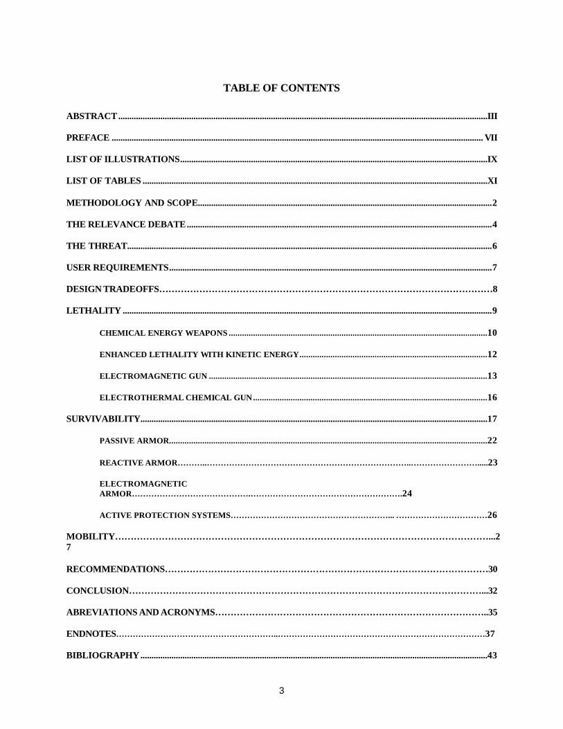
Figure 2
FCS PROGRAM GOALS• C-130 transportable (<20 tons)• 33-50% Decrease in logistics sustainment requirements• 50% Decrease in fuel consumption• 96 hours rapid response • 5 days OPTEMPO operation without resupply• 100 KPH burst speeds • 60 KPH cross country speed-sustained• And should:
– Survive first round engagement– Maximize commonality– Have joint & international interoperability– Embed training & human factors
Source: Briefing by LTC VanFossun during the FCS Industry Day, 11 January, 2000
User Requirements
Three characteristics of today’s M1/M2 duo emerge as most responsible for their success -
lethality, survivability, and mobility. These characteristics not only engender enormous confidence among
their own crews, they also have the opposite effect among enemy troops – literally scaring the hell out
them and causing them to lose confidence in their own capabilities and equipment. A logical extension
then would be that the Army should ensure similar characteristics are factored into the design of any
future combat systems. Not surprisingly, the Army considers responsiveness, deployability, agility,
versatility, lethality, survivability, and sustainability to be critical factors in achieving dominance throughout
the entire spectrum of future conflict.19
To achieve that end, the Army and the Defense Advanced Research Projects Agency (DARPA)
have joined in partnership to develop a multi-mission system-of-systems concept for the FCS. Their
mission is to design, develop, and field a system at an unprecedented pace, with the first unit equipped
by 2012.20 Foremost, the system must be light and rapidly deployable in order to support the Chief’s
vision. It must be survivable, provide significant combat overmatch against all foreseeable threats and it
must significantly reduce the Army’s logistics burden (Figure 2).
The identification of user
requirements is one of the most
critical steps in the developmental
process. It is during this initial
process that the user articulates
what he expects in terms of
capabilities and performance
parameters that, in turn, dictate
design specifications. The
requirements are ordinarily captured
in the Mission Needs Statement
(MNS) and, in the Army’s case, are
normally developed by the U.S.
Army Training and Doctrine
Command (TRADOC). At the time of publishing, the MNS was in its draft form. According to that
document, the Mission Need for the Future Combat System is as follows:

14
Figure 3FCS Functions
MULTIMULTI --MISSIONMISSIONCOMBAT SYSTEMCOMBAT SYSTEM
INDIRECTFIRE
AIRDEFENSE
SUPPORT COMBATSUPPORT
COMBATSERVICESUPPORT
SITUATIONALUnderstanding TROOP
TRANS.
NON-LETHAL
MOBILITY/COUNTER-MOBILITY
C4I
DIRECTFIRE
Source: Briefing by LTC VanFossun during the FCS Industry Day, 11 January, 2000
Mission. Army combat forces must be capable of rapid unit deployments both for early entry and follow-on forces. These entire units must be able to immediately deploy with full combat capabilities anywhere on the globe and, without pause or preparation and regardless of the non-permissive, semi-permissive or permissive access conditions, be capable of conducting operations to dominate the threat and win. Overmatch must be achieved through an integrated platform design, systems integration, organizational design, and advances in training and leader development. This domination will be achieved through overmatch in lethality, survivability and standoff capabilities. To that end, these forces must be equipped with the FCS, which will be a family of individual combat systems.
Source: Mission Needs Statement (Working Draft) for Future Combat System (FCS) Capability
The language is broad but this statement is significant for its reference to unit deployments with
full combat capabilities, implied forced entry, overmatch capability, and a family of combat systems. It
also articulates the objective of providing a lethal, survivable, and sustainable FCS-equipped land force,
capable of rapid deployment and immediate employment as a unit upon arrival to defeat any threat well
into the 21st century.21 These functional characteristics are important in that they represent the user’s
performance expectations but they are profound for what they exclude - the ability of existing combat
systems to meet the stated requirement. Today’s heavy forces are incapable of deploying as units with
full combat capability and because of the need for substantial port and airfield infrastructure, are ill-suited
for forced entry. Similarly, the requirements for overmatch and survivability beg a force that is more
robust than extant light forces. So, assuming the performance requirements can be justified, the Army
appears to have demonstrated a need.
Design Tradeoffs
The armor/anti-armor field has been a continuous horserace between penetration levels and
armor protection levels with neither side holding
the lead for very long.22 Each incremental
improvement in either the penetration
capabilities of the projectile or protection levels
of the armor caused an increase in resultant
vehicle weight. New and better armament
systems (read heavier) lead to subsequent or
parallel improvements in armor (also heavier),
which begs an even bigger cannon (heavier yet),
better armor (heavier still), and so on. Mobility
requirements also demand bigger engines,
beefier drivetrains, and heavier suspension
systems to accommodate the incremental weight - an endless succession that has resulted in the 70 ton
behemoths we have on the battlefield today.

15
With this precedent, it seems nearly inconceivable that a vehicle less than one-third the weight of
an Abrams could rival a modern main battle tank. To get there from here the Army is changing the way it
thinks about armored warfare. TRADOC’s answer to the problem is the development of a system of
systems – not a single vehicle with a solitary role but suite of networked platforms that perform numerous
functions in symphony (Figure 3).
System of Systems
The FCS force will be structured to exploit information dominance through a collection of fighting ensembles. This team achieves battlespace situational understanding by employing a common relevant operating picture. The result will be a synergistic interdependence in which the product of every sensor is tied to every shooter. The FCS force will consist of a combination of manned and unmanned air and ground elements. Each element depends on the other for protection as well as lethality. The net effect is an Abrams-like capability in a much lighter, more lethal and survivable platform. Its ability to engage targets is no longer constrained by the range of its own direct or indirect fire weapons. Its ability to sense the battlefield, process that information while understanding friendly and enemy situations, decide the best method of engagement, and act decisively within the enemy’s decision cycle are key to its success.
Source: Mission Needs Statement (Working Draft) for Future Combat System (FCS) Capability
This system of systems approach is likely to involve numerous components that act in harmony to
perform the required functions. The system will in all probability include ground and air components, with
some of them manned and others being robotically controlled. For the purpose of this discussion, we will
limit focus on an examination of the primary weapons platform and will not address peripheral airborne or
robotic components. What follows therefore, is a brief examination of the more relevant technologies
affecting lethality, survivability, and mobility of the manned weapons platform.
Lethality
The fundamental mission of the main battle tank (MBT) is to close with and destroy the enemy.
Its purpose is to protect its crew so they can safely serve the main gun23 and live to fight another day.
Conventionally speaking, there are primarily two technologies commonly employed on today’s combat
vehicles – kinetic energy and chemical energy weapons. Both are being considered for the FCS.
Modern tanks destroy enemy tanks by using large cannons designed to deliver a tremendous
amount of kinetic energy (measured in mega-joules) against their targets. Conventional tank cannon are,
in the simplest terms, single-stroke, single-piston heat engines that can weigh up to three tons and be as
long as 25 feet. The guns are fueled by solid propellants that produce pressures in excess of 100,000
pounds per square inch to propel projectiles, with diameters of up to 5½ inches, at incredible velocities.
The bore surfaces must endure extremely high pressures, temperatures, and friction while guiding and
launching projectiles at targets thousands of meters away, and they must do this for thousands of rounds.
The breach mechanism must open quickly for loading yet seal propellant gases that will exert over three

16
million pounds of force in an effort to escape.24 In essence, a kinetic energy round depends on its speed
and mass to pierce its target. In order to maximize speed and velocity, KE projectiles must be
manufactured from the densest materials possible and have as small a cross section as possible. The
result is an arrow or dart-like projectile of tungsten or depleted uranium with length-to-diameter ratios of
approximately 20:1. This type of penetrator is referred to as an armor piercing, fin-stabilized, discarding
sabot or APFSDS.25
With conventional kinetic energy technologies, there are only two ways to boost the muzzle
energy of the projectile - either increase the mass of the projectile or increase its velocity and regrettably,
both lead to larger and heavier guns. The former necessitates an increase in gun caliber, which means a
larger breach and a heavier cannon. Assuming no change in projectile mass, the latter means higher
chamber pressures and a larger gun to contain them.
Using solid propellant technology, the 120mm cannon on the U.S. M1 tank delivers approximately
9 megajoules (MJ) of muzzle energy26 and is capable of destroying nearly any target on the modern
battlefield. No doubt it is sufficiently lethal today, but studies conducted in Switzerland and elsewhere
indicate that successful frontal attacks against future improved armors will require guns that fire APFSDS
projectiles with muzzle energies of about 18MJ. As a result, the U.S., France, Germany, and the UK have
done some work on larger guns and agreed on 140mm as the standard caliber. Their work demonstrated
that guns of such caliber are fully capable of achieving 18MJ of muzzle energy, but the prospect did not
prove popular because of the added size and weight of the gun and ammunition.27
The laws of physics coupled with the sub-20 ton goal for the FCS platform essentially eliminate
conventional cannon as a viable 18MJ armament candidate so the challenge will be to find a lighter, more
efficient alternative. Other options include chemical energy (CE) weapons and leap-ahead kinetic energy
(KE) weapons that promise hypervelocity projectiles (>2,500m/s)28 by deriving energy from either
electrical energy or a combination of electrical energy and conventional propellants.
Chemical Energy Weapons
Combat system designers often turn to anti-tank guided missiles (ATGMs) as an efficient
alternative to the tank cannon. ATGMs employ chemical energy as opposed to kinetic energy and
because the missile is self-propelled, they permit a lightweight launcher instead of a heavy cannon,
thereby reducing the weight burden on the platform. CE weapons are efficient in perforating armor
because they convert the chemical energy of high explosives into mechanical energy in the form of a very
fast jet to attack the target. The high explosive is usually shaped around a conical cavity that is lined with
metal. When the ‘shaped charge’ (Figure 4) explodes, the metallic cone collapses under tremendous
pressures that compress the copper liner into a narrow, extremely fast, jet of copper particles and gas. At
the time of the explosion, particles at the tip of the jet assume a higher velocity than those at the rear,
resulting in a velocity gradient and an ever-elongating jet. The tip of a typical jet travels at speeds

17
Figure 4
Shaped Charge Technology
The shaped charge with copper liner
Jet formation and elongation upon detonation
Source: Rank Enterprises, Inc., Website http:www.fortunecity.com/skyscraper/siliconex/575/body_reactive.html, accessed 25 Oct 99.
approaching 10,000 m/sec while the rear, or slug, travels at much slower velocities (approximately 1,000
m/sec).29
When a shaped charge jet strikes a target of armor plate, pressures on the order of hundreds of
kilobars are produced at the point of impact. The pressure produces stresses far above the yield strength
of steel, so the target material
flows like a fluid out of the path
of the jet. This phenomenon is
called hydrodynamic penetration
and the depth of penetration is a
function of the length of the jet,
density and hardness of the
target material, and the density
and quality of the jet. As a rule,
the longer the jet, the greater the
penetration, which is true until
the jet begins to break up or
particulate as a result of the
velocity gradient. Optimal
performance is obtained by
detonating the shaped charge at some distance from the target, typically 6 to 8 diameters of the cone.
Effectiveness is also a function of jet precision or straightness, which, to be discussed later, can be
disrupted by certain active armors.30
Typical large ATGMs can penetrate hundreds of millimeters of rolled homogeneous armor (RHA)
and effective ranges of 4,000-5,000 meters are not uncommon. Integrated guidance systems now offer a
“fire and forget” capability that eliminates the disadvantage of gunner exposure while he optically guides
the missile to the target. Another advantage with this technology is that warhead and missile
improvements can be developed and integrated independently with no need for major changes on the
platform itself.
Cost and stowed-kill capability rank among the most significant disadvantages of ATGMs. This
technology is comparatively mature and costs will continue to come down, but it is unlikely they’ll ever be
as cheap as KE rounds. Stowed-kill capability represents the number of potential enemy targets that can
be destroyed with a basic load on a given weapon platform. For example, the Abrams basic load
includes a maximum of 40 main gun rounds - or a stowed-kill of 40 (assuming a probability of kill of 1.0
per round). Because of the larger missile components, ATGMs require more stowage space than KE
rounds so stowed kill capabilities are usually lower on missile platforms. The M2 Bradley, for example,
will only stow 5-7 rounds plus two in the launcher for a total stowed-kill of 7-9.

18
Source: Briefing by LTC VanFossun during the FCS Industry Day, 11 January, 2000
Figure 5Missile in a Box
Recent CE weapons developments may offset the cost and stowed-kill disadvantages and may
be a viable candidate for application on the FCS. Called “Missile in a Box”, the idea is to package
multiple missiles in a single box to
increase stowed-kill capability and
reduce costs per round. As the
conceptual diagram in Figure 5
illustrates, the stowed kill would be
relatively high (16) and offers the
advantage of not having to
individually load each missile into the
launcher such as is the case with the
Bradley Fighting Vehicle. It also
offers the advantage of enhancing
survivability because it is a non-line-
of-sight weapon that permits the crew
to employ the system from a fully covered and concealed position. By packaging multiple missiles in a
single container, crew-handling requirements and reload time can be greatly reduced.
ENHANCED LETHALITY WITH KINETIC ENERGY
The Army and industry have been investigating novel concepts for defeating advanced targets
such as reactive armor or active protection systems by launching KE projectiles at hypervelocity. The
most promising concepts involve launching projectiles using electrical energy either exclusively, such as
with Electromagnetic (EM) guns, or in conjunction with the chemical energy created by conventional
propellants - a process called electro-thermal-chemical (ETC). EM launch is an approach that uses
electromagnetic energy to launch the projectile, while ETC yields significant performance improvements
of conventional guns by using electrical energy to control the release of chemical energy from propellants.
While both offer tremendous potential for lethality improvements, much developmental effort is needed
before they will reach technological maturity. ETC is the more mature of the two and may be applicable
to future combat platforms with tests already having been completed on the 120mm tank cannon.31
Nonetheless, there are significant hurdles to overcome before the concept can be reliably applied to light
armored vehicles.

19
Electromagnetic Gun
Electromagnetic gun technology is not nearly as new as its leap-ahead performance potential
would suggest. As far back as 1987, FMC Corporation conducted a design study for DARPA of an
armored vehicle with a 15MJ electromagnetic gun and concluded that a prototype could be developed by
as early as 1991. A DARPA-sponsored study reached a similar conclusion a year later - expecting to
demonstrate components of an 11MJ tank destroyer by 1992. At about the same time, UK experts were
similarly optimistic - with Royal Armament Research and Development Establishment proposing a tech
demo of an EM gun on a Chieftain chassis by 1987. For as old as the technology is, it is interesting to
note that not a single vehicle armed with an EM gun has been developed.32
The EM gun is commonly referred to as the rail gun because an electric impulse is passed
through two parallel rails between which the projectile is sandwiched (Figure 6). With conventional
propellants, projectile velocity is limited by the speed of the chemical propagation within the chamber (the
speed of sound). The EM gun, on the other hand, uses electrical energy to create a magnetic field to
propel the projectile at velocities with a theoretical limit (my emphasis) of the speed of light. To illustrate
the potential for improvement, conventional 120mm tank main guns obtain muzzle velocities of no more
than 1,800-2,000 m/sec. Rail guns on the other hand, are realistically expected to launch hypervelocity
projectiles at up to 4,000-8,000 km/sec and produce 30-60MJ of muzzle energy.33 The Defence
Evaluation and Research Agency (DERA) in the UK has already launched realistic 90mm APFSDS
projectiles at velocities of up to 1,730m/s and proof shots up to 2,340m/s. US engineers have launched
projectiles at rail launch facilities at up to 4,000m/s, albeit with less realistic projectiles. DERA projectiles
hit targets at battlefield ranges of up to 2,000m, while those launched in US facilities flew only a few
meters in laboratory conditions.34
PrimePower
PulsedPowerSupply
Conducting Rails
ProjectileArmature
Source: Briefing by LTC VanFossun during the FCS Industry Day, 11 January, 2000
Figure 6
Concept Sketch - Electromagnetic Gun

20
EM systems offer a number of advantages. Because they are powered by electric energy, they
can be “tuned” to optimize performance against specific targets by simply varying the amount of current
supplied to the rails. Hypervelocity projectiles appear to be more effective against some armors but less
so against others. Although contrary to the familiar principle that lethality increases with the velocity of
the projectile, effectiveness actually peaks at different velocities depending on the type of projectile and
the target. Against homogeneous steel armors, the effectiveness of long rod penetrators decreases after
about 2,200m/s. Against armor targets incorporating ceramics, the optimum velocity is in the region of
2,600m/s. Finally, velocities as high as 3,000m/s may be required for maximum effectiveness against
reactive armor.35 Hence, it is advantageous to be able to adjust projectile velocity before launch.
Projectile homogeneity also affects performance against certain advanced armors. Effectiveness against
explosive reactive armor increases if the projectiles are segmented while homogeneous penetrators are
more effective against some of the complex composite armors.36
Electrical energy is much simpler to transport, handle, store, and control than conventional
propellants so its contribution to simplified logistics seems to tip the scale in favor of the EM gun.37 Note,
however, that while electric energy ranks among the EM gun’s advantages, practical application is
problematic and will be discussed later.
The impressive results to date have been achieved with laboratory EM launchers and not with
fieldable EM tank guns and viable EM guns will not be feasible until engineers overcome significant
technological hurdles. The most pressing challenge for the EM technology is developing mechanisms to
produce the pulsed electrical power for the system. EM railguns operate on essentially the same
principle as electric motors. That is, a high current is supplied to highly conductive rails, which creates a
strong magnetic field (on the order of 20-40 Tezla38) generated by the resultant electric arc across the
rails. About ten years ago, laboratory results produced muzzle energies of 9MJ with velocities of 2,500-
4,000 m/sec, but the device needed to power the system weighed 20 tons39 - the entire weight budget for
the FCS. Encouraging progress has been made since then but current power systems are still about the
size of a standard office desk and weigh between 1-2 tons - still too large and heavy for the FCS.40
Beyond the production of electrical energy, the storage of electrical energy also remains a
considerable problem. Efforts in the early 90s focused on capacitors for storage with optimistic
projections leading to predictions that the energy density of capacitors would reach 63MJ/m3. An EM gun
that would generate only 9MJ of muzzle energy would have required a capacitor bank of about 32MJ and
it would occupy about 0.5m3 – a practical goal for tank installations. Unfortunately, the best that has been
achieved thus far is capacitors with an energy density of 2.5MJ/m3. If such a capacitor were used in the
9MJ muzzle energy case, it would require a volume of 12.8m3 – equivalent to the total hull space of the
Russian T-72. With even the latest estimates of energy densities of 7MJ/m3, the 32MJ bank would still
occupy as much space as the power pack in a modern battle tank.41

21
The U.S. Army Research Laboratory is now working on rotating machines, called compensated
pulsed alternators, or compulsators, to provide higher energy densities than capacitors (Figure 7). This
technology has been under development since the early 1980s at the University of Texas at Austin.
Compulsators are considered capable of storing as much as 135MJ/m3 but they must rotate at
tremendous speeds if their size and weight are to be minimized. Despite mechanical problems this
creates, UT efforts appear very promising. That notwithstanding, application of this technology to a 15-20
vehicle remains a distant goal.42
Aside from energy storage, EM
rail guns face other design challenges.
Fieldable EM guns must be much
lighter than the massive launchers
used under laboratory conditions.
Unlike their simple conventional gun
counterparts, rail launchers are
complex mechanisms that must
contain 3-4 million amps of electrical
energy within light but adequately stiff
and strong structures and so far,
attempts have failed. There is also the
challenge of integrating the EM gun
system into the vehicle, to include the
myriad electrical power transmission
components such as cables, busbars, connectors, and rotary junctions capable of transmitting mega-amp
currents. Finally, human factors such as the potentially adverse effects of the magnetic fields on the
vehicle crew must be addressed. The magnetic fields will have to be attenuated to safe levels, which is
tantamount to creating a magnetic enclosure around the crew compartment; but any openings, which will
be difficult to avoid, will greatly reduce the effectiveness.43
Electro-Thermal Chemical Gun
Encouraging results have also been obtained with ETC guns, which employ a chemically
energetic liquid instead of conventional solid propellant. Unlike conventional propellants, where
detonation pressures quickly diminish as the projectile moves down the barrel, the ETC process regulates
the pressure at near its maximum as the projectile departs the combustion chamber. The technology is
Figure 7
Compulsator Power Supply
Source: Briefing by LTC VanFossun during the FCS Industry Day, 11 January, 2000

22
recognized by many as showing promise of infinitely variable lethality with the added advantage of
requiring significantly less electrical energy in comparison to the EM gun.44
Again, this technology is not new. The Soreq Nuclear Research Center in Israel has pursued it
since 1986 where it progressed by 1993 to field tests with a 105mm ETC gun. Germany has done ETC
since 1986, which evolved into a Franco-German bilateral program in 1991.45 Premature attempts to
convert 120mm solid propellant tank guns into ETC were made in the U.S. as long ago as 1989.
Over the course of their development, ETC guns have been radically transformed. It began with
attempts to attenuate the high-temperature effects of electrical discharges on projectiles by inserting a
fluid between them from which propulsion pressures were generated. Because the fluid was inert, all of
the propulsion energy was electrical and early guns were therefore electrothermal (ET). Work continued
in Germany until, in 1995, they launched a 2kg projectile at 2,400m/s from a 105mm ET gun. Despite the
impressive results, these guns consume at least as much electrical energy as EM guns and possibly
more due to the inherent requirement to convert electrical into kinetic energy. As a result, ET guns
require the same electrical storage systems as EM guns and are not yet a feasible proposition for lightly
armored vehicles.46
By replacing the inert fluid with an energetic fluid, or slurry, a chemical reaction occurs in the
chamber, which upon ignition contributes energy to the propulsion of the projectile while drastically
reducing the amount of electrical energy required. As work continued, the amount of electrical energy
decreased to as little as 6% of the total propulsion energy and while this led to significant improvements,
engineers began to see more promise in solid propellants than energetic fluids.47
Pioneered by Soreq, solid propellant ETC has been pursued in the U.S. since the early 1990s
and more recently in France and Germany. Initially, ETC guns increased muzzle energies by adding an
electrically generated plasma jet to the combustion process, yielding muzzle velocities of 2,000-2,500m/s.
Unfortunately, chamber design pressures limited the amount of electrical energy that could be inserted
into the chamber during initial combustion and injecting it at a later stage proved inefficient.48 Yet again,
considerable amounts of electrical energy were required to obtain high velocities.
The latest designs use electrical energy in the form of a powerful plasma igniter. With this
method, the chemical process can be controlled and chamber pressures regulated with much less
electrical energy – as little as 0.5MJ and currents between 10 and 30kA (vice 3000-4000kA). This
breakthrough makes ETC much more feasible for installation on armored vehicles and it offers several
advantages over conventional, solid propellant guns. The plasma igniter makes higher propellant loading
densities possible, implying more energy for projectile propulsion. The intense jet also allows lower
vulnerability propellants to be used, which means a safer environment for the crews.
Although there are advantages, several issues must be addressed, not the least of which is
systems integration. With three components (projectile, propellant, electrical energy) the technology
requires considerable developmental work before full integration will be possible. Furthermore, the higher

23
chamber pressures will require a sizeable cannon that may consume more of the weight budget than is
acceptable.49
SURVIVABILITY
Because of the extraordinary lethality of modern anti-tank weapons, many regard crew
survivability as the most significant challenge for designers of light combat systems. Armored vehicles
have become increasingly vulnerable to a wide range of threats, ranging from small arms to shaped
charge warheads, long rod penetrators, top-attack munitions, mines, and chemical weapons.
Table 1
Component Weights (lbs)
LAV AGS M2A2 M1A2
Hull 8,680 9,200 32,960 38,880
Suspension 6,060 7,420 12,120 24,350
Power Plant 3,970 6,500 6,970 10,660
Aux. Auto 1,800 1,980 2,170 3,960
Wpn Station 3,500 9,810 7,520 43,900
Fire Control Included in WS 700 1,370 3,770
Ammunition 1,190 1,990 2,570 3,590
OVE 890 920 2,160 3,070
Fuel 510 1,080 1,320 3,580
Crew 2,180 760 2,200 840
Total 28,780 40,360 71,360 136,600
Tons 14.4 20.2 35.7 68.3
SOURCE: U.S. ARMY TACOM/TARDEC BRIEFING ON THE 20-TON WHEELED HYBRID WEAPONS CONCEPT
Furthermore, weight, mobility, and fuel consumption constraints no longer allow engineers to improve
protection by simply inserting more heavy, homogeneous armor between the crew and the projectile.
And since long rod penetrators and ATGMs can destroy even the most modern and heavily armored main
battle tanks, it will take a leap of faith to expect a 20-ton chassis to survive a direct hit. In fact, the Army
no longer expects the FCS to survive a direct hit, which is to say the Army is changing the way it thinks
about survivability.
24
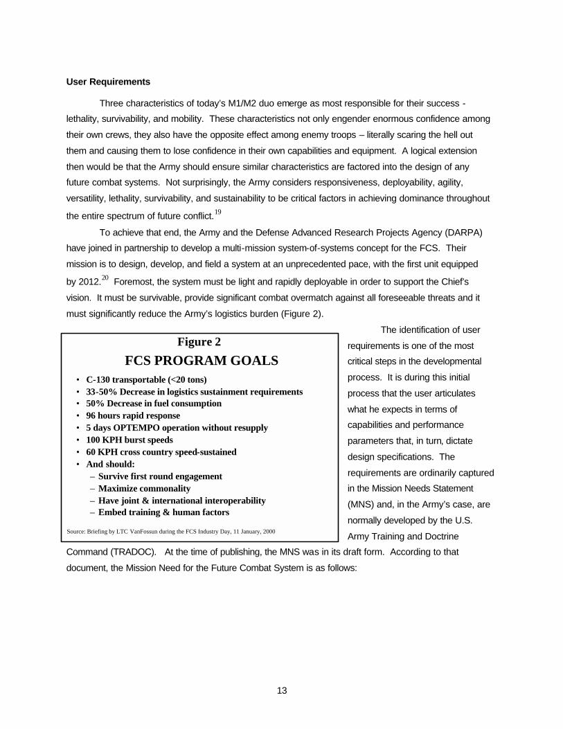
Armored vehicle design has always included tradeoffs. The survivability package must compete
with all of the other subsystem components for its share of the total design weight, so any incremental
increase in the weight of one subsystem compels a commensurate reduction among the remaining
components. With the obvious need for a complete system that incorporates survivability, armament,
propulsion, and drive train components, the test will be to develop an effective survivability package within
available weight constraints.
Table 1 highlights the magnitude of the issue by presenting weight data for some conventional
combat vehicles. On even the lightest vehicles, structural components consume a significant portion of
the total design weight. For example, the hull, suspension, and propulsion components on the LAV weigh
11,830 pounds, or 41 percent of the total system weight. The same components consume 62 percent of
the available weight on the Armored Gun System (AGS), 76 percent on the M2A2, and 57 percent on the
M1A2 main battle tank. The three lighter vehicles are designed for all-around protection against heavy
machine guns and will not survive engagements from even hand held high explosive weapons such as
the RPG7. Of the four, only the M1A2 is able to survive first round frontal impacts against tank main gun
rounds and ATGMs. Unfortunately, this protection comes at a cost of approximately 39 tons – nearly
twice the weight goal of the FCS.
With the 20-ton constraint, it appears crews will no longer be able to simply rely on the physical
structure of their vehicles for protection. Survival will increasingly depend on how well they can avoid
potential threats and, if engaged, whether the system can degrade the inbound threat before it impacts
the hull. `The Army calls it “Full-Spectrum Active Protection” - encompassing detection, hit avoidance,
penetration avoidance, and kill avoidance.
In early 1999, the Commanding General of the U.S. Army Training and Doctrine Command, the
Deputy Assistant Secretary of the Army for Acquisition, Logistics, and Technology, and the Deputy Chief
of Staff of the Army for Operations and Plans tasked the Army Science Board (ASB) to conduct a study to
investigate the potential for advanced technology to meet ground combat vehicle protection requirements
anticipated for 2025. Their report, entitled “Full Spectrum Protection for 2025-Era Ground Combat
Vehicles” was released in July 1999. As illustrated in Figure 8, the board determined that it would be
reasonable to allocate approximately 5-9 tons for survivability and structure on a 20-ton platform,
depending on the choice of the weapons system.50

25
0
5
10
15
20
Conv/T
rack
Conv/W
hl
Elec/T
rac
Elec/W
hl
Conv/T
rack
Conv/W
hl
Elec/T
rac
Elec/W
hl
Conv/
Track
Conv/W
hl
Elec/T
rac
Elec/W
hl
Crew &MiscPower MgtPropulsionLethality
Structure/Surviv
Conv / ETC Lethality Missile Lethality EM Lethality
Weight(tons)
Mobility Configuration
Figure 820-Ton Vehicle Weight Distribution Tradeoffs
Source: Army Science Board, FY99 Summer Study “Full Spectrum Protection for2025-Era Ground Combat Vehicles”, Final Report, 17 Aug 99
The sobering reality is that even the most advanced conventional armor systems will come
nowhere near providing the desired levels of all-around crew protection within those weight constraints.
In the course of its study, the Army Science Board examined survivability options for a notional 20-ton
vehicle using current technologies. It determined that to provide minimal frontal protection against large
caliber KE penetrators for only a small area in front of the crew compartment and protection against
lesser threats on the balance of the vehicle, current technologies would exceed the weight allocation by a
factor of 4 or more. The ASB could meet protection goals using the best technologies it could predict for
the 2005-2010 timeframe, but it would not protect the usual 60-degree frontal arc. Only an area of about
10 square feet in front of the crew would be protected against all threats and the balance of the vehicle,
with the exception of the rear, would protect against lesser threats.51
As KE projectiles become more and more lethal, FCS engineers will also have to consider the
harsh realities of impact physics. “Kinetic” is derived from the Greek word “kinema,” which means
“motion,” and kinetic energy is represented by the following equation:
Kinetic Energy = KE = ½ MV2
Where: M = the mass of the projectile in kilograms
V = the velocity of the projectile in meters per second
Among the most significant concerns for FCS engineers will be the task of containing the kinetic
energy delivered by advanced penetrators. Hypervelocity projectiles present an intimidating problem and,
since we expect 18MJ penetrators in the near future, it is important that we understand the difficulties
associated with defeating them. Because kinetic energy is proportional to the square of velocity, major

26
increases in penetrator velocity result in frightening amplifications of impact energy. For example, the
impact energy delivered by a direct hit from an 18MJ penetrator is roughly equivalent to that of another
20-ton vehicle slamming into a stationary FCS at over 72 kilometers per hour! Even if the armor was
able to prevent penetration, the impact shock will certainly cause severe internal vehicle damage and will
probably incapacitate the crew. This physical reality has led the Army to concede that it is highly unlikely
a 20-ton vehicle will survive given a direct hit.52 The impact shock that accompanies a direct hit by a long
rod penetrator makes the armor’s ability to contain the projectile within its own envelope nearly
immaterial.
Kinetic Energy Example
Mass of the vehicle = 20 tons (or 88,000kg)
Velocity of the vehicle = 72km/hr (or 20.22 m/sec)
KE = ½ MV2
KE = ½ 88,000 x (20.222)
KE = 18MJ
As menacing as the KE threat seems, the impact energy of shaped charge weapons is no less
horrifying. As previously discussed, the detonation energy of a shaped charge is concentrated into a
conical liner, producing a jet of intensely hot plasma. This jet is capable of producing penetration
pressures ranging from 1-10 million kg/cm2 or more – the equivalent of up to 10-million atmospheres.
Small shaped charges, of the type found in hand held HEAT configurations are capable of penetrating 10-
12 inches of rolled homogeneous armor (RHA), while a large shaped charge can penetrate 20 inches of
armor.
The problem is intensified by the fact that optimal protection against one type of threat does not
guarantee success against the other. KE and CE weapons have different characteristics that require
different mechanisms to defeat. Consequently, FCS engineers must tackle what has long been a tacit
reality within the Armor community…if you can be seen, you can be hit… and if you can be hit, you can
be killed. This leads to an intuitive conclusion that survival on tomorrow’s battlefield is perhaps more a
function of hit avoidance than survival given a hit. The strategy, as depicted in Figure 9, is a global
approach to survivability that will depend as much on not being detected, acquired, or hit as it does on
preventing penetration and a kill given a hit.

27
Signature reduction
JammersDecoysActive Protection
Passive armorReactive armorEM armorSmart armor
ObscurantsJammers
Killed
Don’t Be ...
Detected
Acquired
Hit
Penetrated
CompartmentingSpall reductionFire suppression
Source: Future Combat Vehicle – a multi-mission system of systems concept, Briefing by Dr. Richard McClelland to the ASB Plenary Session, 13 Apr 99
Figure 9
Survivability Strategy
Among the keys to avoiding detection is the concept of signature management – reducing the
visual and acoustic evidence of the vehicle on the battlefield. Reducing the vehicle’s size, camouflaging
its silhouette, attenuating engine and drive train noise, and reducing exposure time have become
compulsory design factors for
future combat vehicles. Vehicle
size is directly related to interior
volume, much of which is
dedicated to crew space, so one
solution to making a smaller
vehicle is to reduce the size of the
crew. By installing an autoloader
for example, we can eliminate one
member of the crew and a
corresponding amount of interior
volume. Some have even
suggested two-man crews where
both members would share
responsibilities for driving and manning the weapons system. This concept has been kicked around for a
number of years but there are major issues that make it impractical. With only two crewmembers, 24-
hour operations would make it very difficult to accommodate crew rest requirements. The assumption in
this case is that each crewmember would be trained to accomplish all functions so one of them could rest
while the other remains on watch. Unfortunately, that leaves only one crewmember awake, which, in
itself would have psychological consequences in a combat environment, and furthermore, leaves no one
on the ground to provide local security. The most likely solution would be to add yet another local
security mission to an already over-tasked infantry unit.
Conventional methods of camouflage, such as special paint schemes and adding foliage to the
outside of the vehicle will no longer suffice given advanced acquisition devices like radar, thermal, and
laser imaging. Borrowing from aircraft stealth technologies, it is possible to significantly reduce radar
cross-section by using radar-absorbing materials and by designing the hull such that the external
surfaces are flat, continuous, and angular. Likewise, rerouting exhaust emissions, installing protective
materials to reduce the “solar loading” effect, and adapting the passive signature of the vehicle to the
background can reduce the thermal signature.
In an effort to address the global issue, the ASB recommends that the FCS rely on a suite of
survivability measures and that it be less dependent on traditional passive armor designs than current
generation vehicles.53 Table 2 includes a list of some of the survivability factors it recommended for
further investigation and potential development.

28
PASSIVE ARMOR
At the risk of oversimplification, providing protection against KE projectiles is a relatively simple
matter. In order to defeat the penetrator, one or a combination of three things typically has to be
accomplished:
- Slow the projectile
- Turn the projectile
- Break up the projectile
Slowing the projectile is usually accomplished by simply putting more armor in its path. This technique
was the primary means of armored protection in early tanks but as penetrators became more effective,
the amount of armor needed to stop them became thicker and heavier - to the point where vehicle
mobility became a factor. Engineers later determined that they could significantly reduce a projectile’s
penetration capability by turning it from the horizontal shotline so that it hit the basal armor broadside
instead of head on. One of the most common ways to turn the projectile involves placing a thin sheet of
‘standoff’ armor a few inches from the basal armor. As the round penetrates the standoff armor, it begins
to turn and, by the time it hits the basal armor, it may be nearly perpendicular to its flight path. Certain
materials possess inherent characteristics that cause the penetrator to turn within the armor after impact.
In the case of aluminum for example, certain KE projectiles turn and run up the length of the armor plate
vice penetrating its thickness after impact.
Table 2Survivability Approach for an Advanced Technology 20-Ton Vehicle Concept
Detection Avoidance• Reduce visual silhouette• Emphasize signature management:
– IR reduction - advanced materials and selective cooling
– Radar reduction - vehicle shaping and materials
– RF and EO emissions
Hit Avoidance• Hard kill and soft kill mechanisms• Requires integrated subsystems
– Early warning sensors– Jammers , spoofers– Obscurants
• Active protection system (CE and KE)
Penetration Avoidance• Innovative vehicle structures with
advanced armors– Frontal arc - Large caliber KE
debris
– Frontal arc - Rapid fire medium cannon and dumb CE
– Flank - Medium caliber and CE missiles
– Top - Fallers, smart munitions
Kill Avoidance• Consolidate and compartment crew
and ammo• Key subsystems:
– Integral shielding/liners– Regenerative overpressure for
crew compartment– NBC detection
Source: FY 99 Army Science Board Briefing on the Final Report, Full Spectrum Protection for 2025-Era Ground Combat Vehicles, 17 August 1999

29
Figure 10Reactive Armor Technology
Source: Rank Enterprises, Inc., Website http:www.fortunecity.com/skyscraper/siliconex/575/body_reactive.html, accessed 25 Oct 99.
Most KE projectiles are quite brittle and that leads to another advantage of using standoff or
spaced armor configurations. Using standoff armors composed of very hard materials, such as high-hard
steel or ceramics often causes the projectile to shatter upon impact. Upon contact, the penetrator breaks
up and the pieces separate as they fly across the distance between the standoff armor and the basal
armor. One particularly effective technique is to use perforated or ‘holey’ armors as the standoff armor.
The material is lighter than homogeneous armor and more effective in turning or breaking up the
penetrator. Ceramic tiles also effectively shatter the penetrator but, because the tiles also shatter upon
impact, do not offer good multi-hit capability.
All armored vehicles derive a degree of protection from their own structural configuration, as even
the lightest armored vehicles require considerable hull structure to accommodate the armament, power
plant, suspension system, and crew. Light vehicle hulls are typically constructed of relatively thin (18-
48mm) steel or aluminum, which protect the crew against small arms and some heavy machine guns
(normally up to 50 caliber or 14.5mm heavy machine guns). Again, however, the challenge is to protect
the crew against medium cannon and larger threats.
The armor community has made significant progress in materials research. Unfortunately,
materiel solutions to contemporary challenges appear to have reached a technical limit – especially for
light vehicle applications. The armor thickness required to withstand larger threats is just too heavy for
practical application on the FCS. Alternative solutions include special armors that can be modularized
and tuned to specific threats. Among the most hopeful candidates are reactive armors and active
protection systems.
Reactive Armor
The terms reactive armor (RA) and explosive reactive armor (ERA) apply to energetic armors that
respond violently to the impact of shaped charge warheads and, in some cases, KE penetrators. While
most of the actual designs are classified, the basic concept consists of a sandwich of two metal plates
with either an explosive or inert energetic materiel
between them. The plates are mounted obliquely
to the path of the shaped charge jet or penetrator
in a manner such that, when attacked, the
energetic materiel reacts causing the two plates to
fly apart (Figure 10). Because the plates fly
obliquely across the path of the jet, they
continuously insert additional metal in front of the
jet, forcing it to penetrate much more material than
the nominal thickness of the plate. The transverse

30
movement of the plates also disrupts the jet or breaks up the KE penetrator. These characteristics make
ERA much more efficient than homogenous armor and allow much greater protection at a fraction of the
weight.
ERA development dates back to the late 70s and early 80s and although originally a German
invention,54 the Israelis pioneered its applications with main battle tanks outfitted as early as 1982. By the
mid-‘80s the Soviet Army had equipped its T-64 and T-80 tanks with ERA tiles.55 The U.S. Army also
developed ERA suites for the M60 tank and Bradley Fighting Vehicle in the mid-‘80s.
The original ERA designs were developed to counter shaped charge anti-tank weapons by using
thin steel plates (2-3mm thick) in the reactive sandwiches. While efficient against CE weapons and some
Soviet designs claiming armor protection three to four times as effective as RHA, these “light ERA”
designs were not very effective against high-velocity KE projectiles. The plates would have to be
considerably thicker to degrade the performance of these weapons – a fact that led to the Soviet
development of “heavy ERA” in the early ‘80s. This design offered no improvement against shaped
charge warheads but the Soviets claimed an overall mass effectiveness of 1.7 against APFSDS tanks
rounds.56
Despite impressive mass efficiency, the application of reactive armor to lightly armored vehicles
still presents unique challenges. Because of its tremendous velocity, the tip of the shaped charge jet
typically penetrates both plates before they begin to move. For this reason, the vehicle hull must be thick
enough to stop the tip before it enters the crew compartment. The basal armor must also be rigid enough
to absorb the tremendous shock of impact of the rear plate as it slams into the vehicle hull upon
detonation. ERA works quite well on main battle tanks because of the significant hull structure and thick
basal armor, but the flying rear plate can cause significant damage to lightly armored vehicles. This
problem will be difficult to eliminate but can be mitigated somewhat by segmenting the explosive in order
to limit the amount of explosive material that detonates.
ELECTROMAGNETIC ARMOR
Electromagnetic armor is a dream dating back to the 1970s. The concept involves mounting two
electrically charged spaced plates above the vehicles basal armor (Figure 11). Upon penetration, the
shaped charge jet creates an electrical short between the plates, producing an intense electrical
discharge and resultant magnetic field around the jet. The magnetic field creates magnetohydrodynamic
instabilities within the jet, thereby disrupting its penetrating capability.57

31
Figure 11
Reprinted from Herskovitz, “Don’t Be Killed…Armored Vehicle Survival,” Journal of Electronic Defense, (Oct 1999): 49-56.
Electromagnetic armor of this type is being considered for use against APFSDS projectiles as well as
shaped charge jets. As in the case of jets, passing a very large electrical charge through the body of the
penetrator also causes fluctuating and distending instabilities that can lead to their disruption.58
A similar concept, called electrothermal armor, also employs two electrically charge plates,
except that, instead of a sizable air gap between the plate, there is a relatively thin layer of active
insulating material. When a jet or KE penetrator pierces the plates, a surge of electrical current causes
the insulating layer to expand explosively, throwing the plates apart with effects similar to that of ERA.59
EM armor relies on capacitor banks to provide the necessary electrical energy, which, like EM
guns, would be considerable. The energy required to launch plates against even contemporary KE
projectiles would be on the order of 1MJ of KE per plate, requiring a 5MJ capacitor bank that would
occupy 5m3 - roughly equal to one-third the internal volume of a modern tank. Even if considerable
advances are made, EM armor is likely to be practical only as part of an all-electric vehicle, i.e., coupled
with an electric gun and electric drive.60

32
Figure 12Typical Active Protection System
Reprinted from Herskovitz, “Don’t Be Killed…Armored Vehicle Survivial ,” Journal of Electronic Defense, (Oct 1999)
Active Protection Systems
Under the Army’s Full Spectrum Protection Program, ARL researchers are working on advanced
protection systems and survivability concepts that may provide adequate protection to armored vehicles
at a fraction of the weight of RHA. The intent of the program is to develop an Active Protection System, a
leap-ahead survivability technology, to effectively defeat all known anti-armor threats, to include KE, CE,
and high explosive anti-tank (HEAT) threats. The concept involves detection and tracking of an incoming
threat and the deployment of a countermeasure to defeat it before it impacts the vehicle structure.61
While technically a leap-ahead technology, active protection systems (APS) have existed for quite
some time. The first operational APS, named Drozd, was developed by the Soviet Union between 1972
and 1982 and was installed on T-55Ads in the early 1980s. The system was designed to provide
protection against ATGMs and antitank grenades by employing primitive millimeter wave radar sensors to
detect incoming rounds and then destroy the threat with fragmentation warheads. The system
experienced a number of shortcomings but was reported to have been approximately 80-percent
successful against RPGs in Afghanistan.62 The French and the Israelis have also experimented with
active protection systems with their Galix and LWS-2 systems respectively.63
Active protection systems are essentially defensive systems designed to intercept, destroy, or
confuse attacking enemy munitions. The objective is to defeat the anti-armor threats within the

33
hemisphere surrounding the vehicle by utilizing two technologies: sensor/information and counter-
munitions technologies.64 The operational concept of active protection systems involves accurate
detection and tracking of the incoming threat followed by the timely deployment of highly accurate
countermeasures to defeat it. This requires an integrated team of advanced sensors, information
processors, armor, and weapons technologies on the vehicle.65
Conventional wisdom for some time has been that active protection against KE penetrators falls
in the “too hard to do” category. Because the penetrators are moving so fast, the acquisition, detection,
intercept, and destruction must occur within extremely minute timeframes. Then again, the Army Science
Board is optimistic and believes that a practical system could be demonstrated within the next few years.
The Board bases its optimism on two beliefs: 1) that sensor requirements to detect and timelines to
intercept are reasonable given projected technological advances in the industry, and 2) it believes
explosive perturbation of the long rod’s trajectory can cause it to miss the intended target. The ASB
concluded that APS could provide excellent protection against KE penetrators except within certain
ranges. For KE penetrators, that would be on the order of 500 meters and for hand held heat it may be
as little as a few tens of meters.66
One of the most critical components of an APS is its counter-munitions system that must kill,
deflect or disrupt tank rounds, missiles and artillery fire. Warheads, armor plates, and other devices
launched from the vehicle platform are being developed as potential APS counter-munitions.
Optimism notwithstanding, the application of APS to light-skinned vehicles involves significant
technical challenges. Successful development of an APS to defeat relatively slow-moving ATGMs and
single KE threats pose challenges of their own but defeating multiple bursts from medium cannons will be
extremely difficult. Similarly, the system must be sophisticated enough to discriminate against small arms
fire and artillery fragments. Like the KE penetrators, these threats must be acquired at further distances,
tracked at higher data rates, intercepted closer to the vehicle, and ultimately absorbed by robust structural
armor.67
MOBILITY
One of the most contentious issues regarding the design of the FCS is likely to be the argument
as to whether the primary platform should be tracked or wheeled. The dispute is nearly as old as combat
vehicles themselves, with the Army having studied the issue for over thirty years. Among the many
tradeoffs to be considered are the vehicle’s mission, terrain profile and vehicle characteristics.
Tankers and mechanized infantrymen venerate tracked systems for their ability to negotiate
virtually any terrain and they consider the move to wheeled vehicles a threat to their communities and,
even worse, a potentially fatal blunder. Some have even accused the Army of stacking the deck in favor
of wheeled technology. United Defense Corporation was especially vocal in its objection during recent
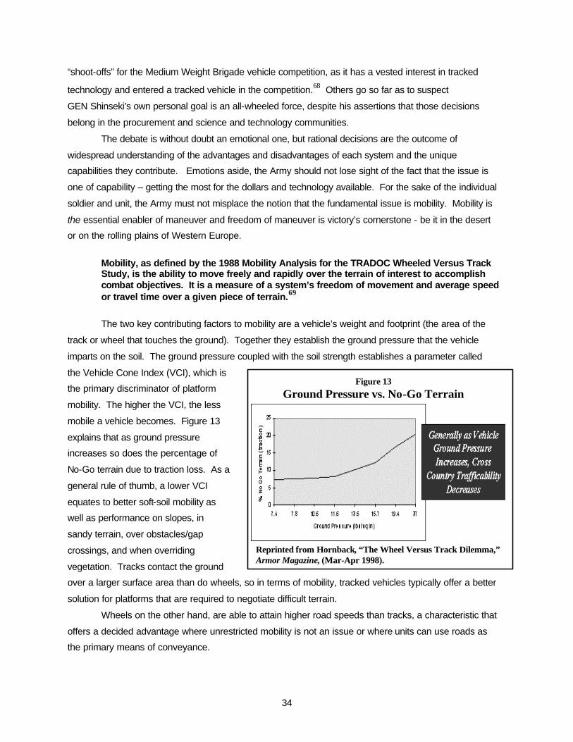
34
Figure 13
Ground Pressure vs. No-Go Terrain
Reprinted from Hornback, “The Wheel Versus Track Dilemma,” Armor Magazine, (Mar-Apr 1998).
“shoot-offs” for the Medium Weight Brigade vehicle competition, as it has a vested interest in tracked
technology and entered a tracked vehicle in the competition.68 Others go so far as to suspect
GEN Shinseki’s own personal goal is an all-wheeled force, despite his assertions that those decisions
belong in the procurement and science and technology communities.
The debate is without doubt an emotional one, but rational decisions are the outcome of
widespread understanding of the advantages and disadvantages of each system and the unique
capabilities they contribute. Emotions aside, the Army should not lose sight of the fact that the issue is
one of capability – getting the most for the dollars and technology available. For the sake of the individual
soldier and unit, the Army must not misplace the notion that the fundamental issue is mobility. Mobility is
the essential enabler of maneuver and freedom of maneuver is victory’s cornerstone - be it in the desert
or on the rolling plains of Western Europe.
Mobility, as defined by the 1988 Mobility Analysis for the TRADOC Wheeled Versus Track Study, is the ability to move freely and rapidly over the terrain of interest to accomplish combat objectives. It is a measure of a system’s freedom of movement and average speed or travel time over a given piece of terrain.69
The two key contributing factors to mobility are a vehicle’s weight and footprint (the area of the
track or wheel that touches the ground). Together they establish the ground pressure that the vehicle
imparts on the soil. The ground pressure coupled with the soil strength establishes a parameter called
the Vehicle Cone Index (VCI), which is
the primary discriminator of platform
mobility. The higher the VCI, the less
mobile a vehicle becomes. Figure 13
explains that as ground pressure
increases so does the percentage of
No-Go terrain due to traction loss. As a
general rule of thumb, a lower VCI
equates to better soft-soil mobility as
well as performance on slopes, in
sandy terrain, over obstacles/gap
crossings, and when overriding
vegetation. Tracks contact the ground
over a larger surface area than do wheels, so in terms of mobility, tracked vehicles typically offer a better
solution for platforms that are required to negotiate difficult terrain.
Wheels on the other hand, are able to attain higher road speeds than tracks, a characteristic that
offers a decided advantage where unrestricted mobility is not an issue or where units can use roads as
the primary means of conveyance.

35
In terms of survivability, tracked vehicles offer other, less intuitive advantages. Apart from their
ability to withstand small arms attacks, tracks contribute to survivability through intrinsic design
characteristics that permit a lower silhouette and as a result, higher survivability. Most tracked vehicles
utilize torsion bar systems that suspend the vehicle and dampen shock by means of steel torsion bars.
One end of the torsion bar is rigidly mounted into the hull and a road wheel arm is attached to the other
end. The wheel itself is mounted onto the road wheel arm and when it hits a bump, the road wheel arm
rises, imparting torque onto the torsion bar. Since steel is naturally resilient, the torsion bar tends to
return to its original position when twisted. The system is very effective and, since it fits under the vehicle
floorboards, requires little hull space.
Wheeled vehicles, on the other hand, require multiple transfer cases and drive shafts in order to
provide power to each individual wheel. According to one Army study, suspension components for
wheeled platforms require up to six times more volume than tracked vehicle components.70 This means
engineers must make tradeoffs between vehicle height and available crew space. There are essentially
two options - allow the drive train components to consume some of the crew and storage space or raise
the crew compartment above the suspension system. Since internal volume is critical, the latter is the
more commonly used option and it results in the relatively tall silhouette common to wheeled armored
vehicles. The downside is that the additional vehicle height makes the vehicle more vulnerable since it
can be more easily acquired and engaged. The larger size also tends to make the vehicle heavier, which
also degrades mobility and deployability.
The inherent weaknesses of suspension system components and tires also make wheeled
platforms more vulnerable to small arms fire and fragmentation from grenades, mines, and artillery fire.
Run-flat tires allow continued operation at limited speed and distances but they must be repaired as soon
as conditions permit. This results in a logistics disadvantage in that more downtime is likely to occur and
more repair parts required.
Tracked vehicles have another mobility advantage in that they have a neutral or pivot steer
capability that allows the vehicle to turn 180 degrees or more within its own length. This capability offers
distinct advantages on narrow roads and during Military Operations in Urban Terrain (MOUT).
On the plus side, wheeled vehicles offer other advantages. They create less noise signature than
tracked systems, primarily due to less vibration and metal-to-metal contact. Improvements in tracked
technology such as Roller Chain Band Track and decoupled running gear have also reduced noise
signatures but they remain noisier than wheeled systems.71 Wheeled vehicles are also offer human
factors advantages over tracked vehicles in that the reduced noise and vibration results in less fatigue for
the crew. Finally, wheels offer another advantage that supports the Army’s goal of reducing the size of
the logistical footprint. By comparison, wheels consume as little as half as much fuel as tracks72 and so;
it directly targets the Army’s largest logistics burden.

36
RECOMMENDATIONS
Without access to classified, close-hold, or proprietary information, it is difficult to predict the
potential of some of the technologies discussed in this paper. That said, some of them appear tailor-
made for a 20-ton vehicle and others promise “leap-ahead” capabilities that warrant further investment
and exploration.
In the area of lethality, the Army should consider investing additional research and development
dollars to missile-in-a-box, electrothermal chemical, and the electromagnetic gun, in that order. The
missile-in-a-box is a relatively mature technology that contributes to both lethality and survivability. The
combination of a lethal warhead with inherently high stowed-kill, engagement range, and accuracy makes
this system worth serious consideration. In spite of the theoretical potential of the ECT and EM guns,
formidable technological hurdles make full-scale application to the FCS by 2012 doubtful. These
challenges notwithstanding, ETC and EM offer potential for true “leap-ahead” capabilities that should be
considered for preplanned improvements to be developed now and integrated at a later date.
As mentioned earlier, making a 20-ton vehicle survivable by today’s standards will be extremely
difficult. By comparison to the M1 tank, the Army will probably have to accept significant degradation in
survivability given a hit and will have to employ additional measures to ensure acceptable protection
levels for its combat troops. Again, I recommend an incremental approach by incorporating the most
technologically mature concepts at the outset and integrating newer technologies later on.
First and perhaps most importantly, engineers should focus on minimizing the size of the vehicle
silhouette. Here, the most promising concept appears to involve limiting the size of the crew to three (no
fewer) in order to reduce interior volume. Furthermore, the crew should be moved as low and as far to
the rear of the vehicle as possible - perhaps by employing a front engine design like the Israeli Merkava.
Providing protection against long rod penetrators and large shaped charge warheads will be
difficult with such a light hull. At a minimum, the hull should offer protection against heavy machine guns
and artillery fragments. Beyond that, the Army should continue development of modular armor systems
such as ERA that can be installed or removed depending on levels of protection required. Another
advantage of modular systems is that they can be independently and continuously developed and then
integrated at a later date.
The Army should certainly pursue the development of active protection systems. Like the ASB, I
believe there is reason for optimism with this system but only given ample resources over time. Despite
concerns over timelines to intercept and sensor requirements, the concept has already been proven on
foreign combat systems. Moreover, “don’t be hit” appears to be the most reliable defense against the
highly lethal threats of the future.
The tracked versus wheeled issue fuels interesting academic debate but the Army must put
mission first. The FCS is a combat system that must be able to negotiate all types of terrain, not just
improved roads. Multiple studies conducted over decades have conclusively demonstrated that tracked
vehicles offer markedly superior mobility on most terrain, lower silhouettes, and greater reliability than

37
their wheeled counterparts. While wheeled vehicles can rightly claim higher speeds, lower noise, and
less fuel consumption, none of these advantages has as direct an impact on mission accomplishment as
the advantages offered by tracked systems. The Army should increase investment in advanced tracked
systems to include lighter materials and noise attenuation.
I would also offer two notes of caution as the Army proceeds with this program. First, the Army
envisions a combat system that will serve a number of diverse roles and must therefore guard against the
propensity for mistaken public perception regarding the system’s capabilities. That is, the Army must
clearly articulate what it expects the system to be and furthermore, what it is not to be. Failure to clearly
identify performance requirements and survivability expectations could severely jeopardize public support
and the ultimate success of the project. A good example is the 1980s case where the Bradley Fighting
Vehicle System endured severe scrutiny because the public thought it was a tank. The critics were
surprised that, with its one and a half inch aluminum hull, it could not survive direct hits from enemy tanks
and hand-held high-explosive antitank weapons. Those weapons represented design overmatch for the
Bradley and the Army clearly did not expect the system to survive against them. Unfortunately, with the
help of some ill-informed critics, the public assumed that any vehicle in the company of tanks on the
battlefield should be designed to withstand tank main gun assaults. Public and congressional
disparagements threatened the program and, were it not for the Gulf War, it may have faced even closer
inquiry and program risk. As it was however, the Bradley performed precisely as designed and delivered
a brilliant performance in the Gulf War.
Secondly, the Army should be careful when describing the product of the Army Transformation as
lighter. On the contrary, as the initiative develops the Army will probably become heavier in the
aggregate, at least in the interim. Of the 10 active divisions, six are heavy armored divisions and four are
light infantry divisions. In relative comparison, the light divisions seem to be struggling to maintain
relevance in today’s busy Army. GEN Shinseki even admitted that our light forces lack staying power,
lethality, and tactical mobility once inserted,73 and with a mission profile that has increased by 300
percent since 198974, the Army is simply too busy to allow 40 percent of its 10 active divisions to sit on
the sidelines. Consequently, the Army’s plan for the Interim Force (between now and when the FCS is
expected to be fielded in 2012) will actually result in heavier light forces. The first units are already being
equipped with the necessary vehicles and equipment to enable sustained operations against a lethal and
determined enemy. As a result, the Army in the aggregate will be heavier, not lighter. In order to avert
future criticism, the Army should be plainspoken about that fact now.

38
Conclusion
The Future Combat System program clearly represents the most revolutionary enterprise the
Army has undertaken in decades, perhaps centuries. Not since the horse, the stirrup, or the tank itself
has any program had the potential for such widespread consequence. It may be that the initiative is not
widely understood, but it is surprising that it has not generated even more controversy.
As any good salesman will tell you, if he wants to sell a product, he absolutely must overstate its
capabilities and understate the limitations and costs. If he doesn’t, it simply won’t sell. This is not to
suggest the Army should discontinue the program, but many experts doubt whether industry will be able
to produce the desired capabilities within preferred timelines. Given the high technological risk
associated with these technologies, the Army risks jeopardizing recognized dominance in pursuit of
greater strategic mobility. By making a decision on any one of these technologies too soon, the Army
clearly risks rushing to failure.
Again, the issue underscores the importance of managing the technological uncertainties. Many
of the technologies discussed offer real potential for leap ahead capabilities but may not be mature
enough by 2003 to justify a selection decision. That said, it would be a shame for some of these
technologies to be shelved because of marginal differences in exhibited capability in three years. This
dilemma could be solved with an acquisition process that fosters technological maturation through
selective investment in some of the most promising candidates. Those chosen could then be brought to
the prototype phase for parallel testing. This strategy is likely to be more expensive and may delay
production and fielding, but it will greatly reduce the risk of premature obsolescence. The advantages
appear to far outweigh the costs. With no peer competitor for our legacy systems in sight, the issue is not
one of parity on the battlefield, at least not for the foreseeable future. Similarly, current investment in the
Medium Weight Brigade concept is a prudent and timely measure that will soon provide a capability to
rapidly deploy forces that are much more relevant in terms of lethality and sustainability. With those two
arguments satisfied, the new acquisition framework is much more likely to deliver leap-ahead capability
when truly required. With adequate time, competition is arguably the most reliable catalyst for delivering
maximum capability at minimum cost.
Meanwhile and although not included in this paper, the Army should aggressively pursue
improvements to strategic mobility by investing in improved airlift and/or sealift. Doing so will increase
capability in either case, whether for contemporary forces or the Objective Force. No doubt, the
deployment, operational, and logistical support costs of today’s Army are high. But to those who argue
that we should reduce those costs I would respond by suggesting that war perhaps ought to be
expensive. The intuitive extension of “war on the cheap” is a government more apt to engage in the
process. With less at stake, these “dime store wars” it seems, will only come more frequently. The intent

39
of course is not to argue deliberate cost growth but human nature often tends to the path of least
resistance, so let’s not make the path to conflict too easy.
Whatever shape it takes, the FCS must provide America’s combat soldiers with the most lethal
and survivable system possible for obtainable dollars. As the 1980s Bradley controversy demonstrated,
the American public is not likely to support a system that places the safety or the lives of our troops at
risk. The Abrams and the Bradley are proven winners and our troops had faith in those systems even
before they rode them into battle. The FCS must engender the same sort of confidence among our
troops because if it can’t, the Army should leave well enough alone and stay with the proven winners.
It is indeed a tough problem and Deputy Defense Secretary John Hamre summed it up quite well
when he recently acknowledged that the Army Transformation is a controversial plan but Army leaders
“deserve credit for tackling a problem that many said was too big.”75 Similarly, Dr. Andrews said that the
Army is literally battling for its soul.76 With these kinds of risks and so much at stake, the Army had better
get it right.

40
ABBREVIATIONS AND ACRONYMS
AGS – Armored Gun System
APFSDS – Armor piercing, fin-stabilized, discarding SABOT
APS – Active protection system
ASB – Army Science Board
ATGM – Anti-tank guided missile
AUSA – Association of the United States Army
BFVS – Bradley Fighting Vehicle System
CE – Chemical energy
DARPA – Defense Advanced Research Projects Agency
DERA – British Defence Evaluation and Research Agency
DPG – Defense Planning Guidance
EM – Electromagnetic
ERA – Explosive reactive armor
ET - Electrothermal
ETC – Electrothermal chemical
FCS – Future Combat System
HEAT – High explosive anti-tank
IR - Infrared
kA - Kiloamps
KE –Kinetic energy
LAV – Light Armored Vehicle
M1 – the Army’s Abrams main battle tank
M2 – the Army’s Bradley infantry fighting vehicle
MJ - Megajoules
MNS – Missions Needs Statement
MOUT – Military Operations in Urban Terrain
MWB – Medium weight brigade
NBC – Nuclear, biological, chemical
OPTEMPO – Operational tempo
OVE – Organic Vehicle Equipment
RA – Reactive armor
RF – Radio frequency
RHA – Rolled homogeneous armor
RPG – Rocket propelled grenade
PSO – Peace support operations

41
TRADOC – The Army Training and Doctrine Command
VCI – Vehicle Cone Index

42
ENDNOTES
1 Long Island Newsday, Dec 6, 1999 Pg. 4.
2 Randall L. Rigby, Lieutenant General, USA, Deputy Commanding General (Futures), U.S. Army Training and Doctrine Command, Briefing to attendees of the Future Combat System Industry Day, Ypsilanti, MI, 11 Jan 2000.
3 George L. Seffers, “Shinseki Unveils All-Wheeled Vision for U.S. Army,” Defense News (Oct 25, 1999).
4 Eric K. Shinseki, General, USA, Chief of Staff of the Army. Statement before the Airland Subcommittee, Committee on Armed Services, United States Senate, Second Session, 106th Congress, 8 March 2000.
5 Harvey M. Sapolsky, “On the Theory of Military Innovation,” Breakthroughs, Volume IX, No. 1 (Spring 2000), 35
6 James D. Thompson, Organizations in Action, In Harvey M. Sapolsky, “On the Theory of Military Innovation,” Breakthroughs, Volume IX, No. 1 (Spring 2000), 35.
7 Stephen P. Rosen, Winning the Next War (Ithica, N.Y., Cornell University Press, 1991), 244.
8 Burton H. Klein, “Policy Issues in the Conduct of Military Development Programs,” In Stephen P. Rosen, Winning the Next War (Ithica, N.Y., Cornell University Press, 1991), 244.
9 George W. Bush Campaign Website, Defense Executive Summary, www.georgebush.com/issues/international/defense/execsumm.asp, accessed 4 February 2000.
10 Eric K. Shinseki, General, USA, Chief of Staff of the Army. Address to the Eisenhower Luncheon, 45th Annual Meeting of the Association of the United States Army, 12 Oct 1999.
11 Edward B. Atkeson, Major General, USA (RET), “Main Battle Tanks: To Be or Not to Be?” Army Magazine (Jan 2000): 40.
12 Robert H. Scales, Major General, USA, “Future Warfare” (May 1999), Available http://carlisle-www.army.mil/usassi/ssipubs/pubs99/futrwar/futrwar.htm, accessed 8 October 1999.
13 Roberto Suro and Bradley Graham, “Army Plans Lighter, More Mobile Forces,” Washington Post (Oct 8 1999): A04.
14 Dr. Thomas G. Mahnken in a panel at the Conference of Strategic Change, Transformation and Military Innovation, Naval War College, 10 March 2000.
15 Dr. Thomas G. Mahnken in a panel at the Conference of Strategic Change, Transformation and Military Innovation, Naval War College, 10 March 2000.
16 Huba Was De Czege and Antulio J. Echevarria II, “Landpower and Future Strategy: Insights from the Army After Next,” Joint Forces Quarterly (Spring 1999): 62-69.

43
17 Antulio J. Echevarria II, “Tomorrow’s Army: The Challenge of Nonlinear Change,” Parameters
(Autumn 1998): 85-98.
18 Headquarters, United States Army Training and Doctrine Command, “Mission Needs Statement (Draft) for the Future Combat System (FCS) Capability,” 1.
19 Neal Anderson, Colonel, USA, Army Transformation Overview Briefing, Slide #2.
20 Ron Laurenzo , “Search For Future Combat System Is Army Priority,” Defense Week (Jan 24, 2000): 1.
21 Headquarters, United States Army Training and Doctrine Command, “Mission Needs Statement (Draft) for the Future Combat System (FCS) Capability,” 2.
22 The Army Science Board, “Full Spectrum Protection for 2025 Era Ground Combat Vehicles, Executive Summary,” (16 July 1999): ES-9.
23 Federation of American Scientists, “Direct Fire Weapons,” http://www.fas.org/man/dod-101/sys/land/direct.htm, accessed 7 October 1999.
24 Benet Laboratories, Tank Cannon Team, www.benet.wva.army.mil/labs/development/ccbdb.html, accessed 3 February, 00.
25 Marsh Gelbart, Tanks: Main Battle Tanks and Light Tanks (London, Brassey’s Ltd, 1996), 5.
26 Dennis Ladd, Deputy Program Manger for EM Guns, telephonic interview by author, Cambridge, MA, 3 Feb 00.
27 R.M. Ogorkiewicz, “Transforming the Tank,” Jane’s International Defense Review (Oct 1, 1997): 30.
28 Roy Beauchamp, Pedro Marrero, Jerry L. Wiedewitsch, “Armour for the XXI Century,” Military Technology (Mar 1998): 76-79
29 Rank Enterprises, Inc., “Shaped Charge Basics,” http://fortunecity.com/skyscraper/siliconex/575/body_reactive.html, accessed 25 Oct 1999.
30 Military Analysis Network, “Big Bullets for Beginners,” http://www.fas.org/man/dod-101/sys/land/bullets2.htm, accessed 25 Mar 00.
31 Electric Armaments, Science & Technology Newsletter, Summer 99.
32 R.M. Ogorkiewicz, “In Search of Lighter, Smaller, Electric Guns for Future Tanks,” Jane’s International Defense Review (Feb 1, 1999): 1.
33 Asher H. Sharoni and Lawrence D. Bacon, “The Future Combat System (FCS): Technology Evolution Review and Feasibility Assessment, Part Two: Armament,” Armor Magazine (Sept-Oct 1997): 29.
34 R.M. Ogorkiewicz, “In Search of Lighter, Smaller, Electric Guns for Future Tanks,” Jane’s International Defense Review (Feb 1, 1999): 1.
44
35 Ibid.
36 Asher H. Sharoni and Lawrence D. Bacon, “The Future Combat System (FCS): Technology Evolution Review and Feasibility Assessment, Part Two: Armament,” Armor Magazine (Sept-Oct 1997): 29.
37 Ibid.
38 Dennis Ladd, Deputy Program Manger for EM Guns, telephonic interview by author, Cambridge, MA, 3 Feb 00.
39 Asher H. Sharoni and Lawrence D. Bacon, “The Future Combat System (FCS): Technology Evolution Review and Feasibility Assessment, Part Two: Armament,” Armor Magazine (Sept-Oct 1997): 29.
40 Dennis Ladd, Deputy Program Manger for EM Guns, telephonic interview by author, Cambridge, MA, 3 Feb 00.
41 R.M. Ogorkiewicz, “Transforming the Tank,” Jane’s International Defense Review (Oct 1, 1997): 30.
42 R.M. Ogorkiewicz, “In Search of Lighter, Smaller, Electric Guns for Future Tanks,” Jane’s International Defense Review (Feb 1, 1999): 1.
43 Ibid.
44 Asher H. Sharoni and Lawrence D. Bacon, “The Future Combat System (FCS): Technology Evolution Review and Feasibility Assessment, Part Two: Armament,” Armor Magazine (Sept-Oct 1997): 29.
45 R.M. Ogorkiewicz, “In Search of Lighter, Smaller, Electric Guns for Future Tanks,” Jane’s International Defense Review (Feb 1, 1999): 1.
46 Ibid.
47 Ibid.
48 Ibid.
49 Asher H. Sharoni and Lawrence D. Bacon, “The Future Combat System (FCS): Technology Evolution Review and Feasibility Assessment, Part Two: Armament,” Armor Magazine (Sept-Oct 1997): 29.
50 The Army Science Board, “Full Spectrum Protection for 2025 Era Ground Combat Vehicles, Executive Summary,” (16 July 1999): ES-12.
51 Ibid.
52 Dr. A. Michael Andrews II, Deputy Assistant Secretary for Research and Technology, Chief Scientist, Office of the Assistant Secretary of the Army for Acquisition, Logistics, and Technology, interview by author, Alexandria, VA, 13 Jan 00.

45
53 The Army Science Board, “Full Spectrum Protection for 2025 Era Ground Combat Vehicles,
Executive Summary,” (16 July 1999): ES-8.
54 R.M. Ogorkiewicz, “Future Tank Armors Revealed: Developments in Electric and Explosive Reactive Armor,” Jane’s International Defense Review (May 1, 1997): 50.
55 Dieter Kahl, “Protection as a Survival Philosophy on AFVs,” Military Technology (Oct 1999): 74-83.
56 R.M. Ogorkiewicz, “Future Tank Armors Revealed: Developments in Electric and Explosive Reactive Amor,: Jane’s International Defense Review (May 1, 1997): 50.
57 Don Herskovitz, “Don’t Be Killed…Armored Vehicle Survival,” Journal of Electronic Defense (Oct 1999): 49-56.
58 R.M. Ogorkiewicz, “Future Tank Armors Revealed: Developments in Electric and Explosive Reactive Amor,: Jane’s International Defense Review (May 1, 1997): 50.
59 Ibid.
60 Ibid.
61 “Reactive Armor – Protection Options for Current and Future Ground Vehicles,” Science and Technology Newsletter, (Spring 99) http://www2.brtrc.com/amc/scitech/library/ Spring99/spr99xtr.htm
62 Tom J. Meyer, Captain, USA, “Active Protective Systems: Impregnable Armor or Simply Enhanced Survivability?” Armor Magazine (May-June 1998): 7.
63 Ibid
64 “Reactive Armor – Protection Options for Current and Future Ground Vehicles,” Science and Technology Newsletter, (Spring 99) http://www2.brtrc.com/amc/scitech/library/ Spring99/spr99xtr.htm
65 Ibid.
66 The Army Science Board, “Full Spectrum Protection for 2025 Era Ground Combat Vehicles, Executive Summary,” (16 July 1999): ES-13-14.
67 “Reactive Armor – Protection Options for Current and Future Ground Vehicles,” Science and Technology Newsletter, (Spring 99) http://www2.brtrc.com/amc/scitech/library/ Spring99/spr99xtr.htm
68 Sean D. Taylor, “Not Backing Off,” Army Times Magazine (Mar 20, 2000): 24.
69 Robert F. Unger, “Mobility Analysis for the TRADOC Wheeled Versus Track Vehicle Study, Final Report,” Department of the Army, Geotechnical Laboratory, Waterways Experiment Station, Vicksburg, Mississippi, (Sept 1981): 1.
70 Paul Hornback, “The Wheel Versus Track Dilemma,” Armor Magazine (March-April 1998).
71 Ibid.

46
72 R.M. Ogorkiewicz, “Weighing Up the Infantry’s Armored Vehicle Options,” Jane’s International
Defense Review, (Mar 1999): 1.
73 Eric K. Shinseki, General, USA, Chief of Staff of the Army. Address to the Eisenhower Luncheon, 45th Annual Meeting of the Association of the United States Army, 12 Oct 1999.
74 Katherine McIntire Peters, “Losing Ground,” Defense Management (August 1999): 8.
75 Sean D. Taylor, “Not Backing Off,” Army Times Magazine (Mar 20, 2000): 24.
76 Dr. A. Michael Andrews II, Deputy Assistant Secretary for Research and Technology, Chief Scientist, Office of the Assistant Secretary of the Army for Acquisition, Logistics, and Technology, interview by author, Alexandria, VA, 13 Jan 00.
BIBLIOGRAPHY
Anderson, Colonel Neal. Army Transformation Overview Briefing. Headquarters, Department of the Army, 2000. Andrews, Dr. A. Michael. Interview by author, 13 January 2000, Alexandria, VA. Tape recording. Army Science Board, The. “Full Spectrum Protection for 2025 Era Ground Combat Vehicles, Executive Summary.” 16 July 1999, ES1-ES13. Atkeson, Major General Edward B.. “Main Battle Tanks: To Be or Not to Be?” Army Magazine, January 2000, 40. Beauchamp, Roy, Pedro Marrero, and Jerry L. Wiedewitsch. “Armor for the XXI Century.” Military Technology , March 1998, 76-79. Benet Laboratories, Tank Cannon Team. Database online. Available www.benet.wva.army.mil/ labs/ development/ccbdb.html. Bush, George W.. “Defense Executive Summary.” Database online. Available www.georgebush.com/issues/international/defense/execsumm.asp. Echevarria, Antulio J.. “Tomorrow’s Army: The Challenge of Nonlinear Change.” Parameters, Autumn 1998, 85-98. Federation of American Scientists. “Direct Fire Weapons.” Database online. Available www.fas.org/man/dod-101/sys/land/direct.htm. Headquaerters, United States Army Training and Doctrine Command. “Mission Needs Statement (Draft) for the Future Combat System (FCS) Capability. Not dated. 1-8. Herskovitz, Don. “Don’t Be Killed…Armored Vehicle Survival.” Journal of Electronic Defense, October 1999, 49-56. Hornback, Paul. “The Wheel Versus Track Dilemma.” Armor Magazine, March-April 1998, 26. Kahl, Dieter. “Protection as a Survival Philosophy on AFVs.” Military Technology , October 1999, 74-83. Ladd, Dennis. Telephonic interview by author. 3 February 2000, Cambridge, MA. Author’s notes. Laurenzo, Ron. “Search For Future Combat System Is Army Priority.” Defense Week, 24 January 2000, 1. Mahnken, Dr. Thomas G.. Member of a panel discussion at the Conference for Strategic Change, Transformation and Military Innovation, Naval War College, 10 March 2000, author’s notes. Gelbart, Marsh. Tanks: Main Battle Tanks and Light Tanks. London: Brassey’s, 1996. McIntire Peters, Katherine. “Losing Ground.” Defense Management, August 1999, 8. Meyer, Captain Tom J.. “Active Protective Systems: Impregnable Armor or Simply Enhanced Survivability?” Armor Magazine, May-June 1997, 7.

48
Military Analysis Network. “Big Bullets for Beginners.” Database online. Available www.fas.org/man/dod-101/sys/land/bullets2.htm. Ogorkiewicz, R.M.. “Transforming the Tank.” Jane’s International Defense Review, 1 October 1997, 30. ________. “In Search of Lighter, Smaller, Electric Guns for Future Tanks.” Jane’s International Defense Review, 1 February 1999, 1. ________. “Weighing Up the Infantry’s Armored Vehicle Options.” Jane’s International Defense Review, March 1999, 1. Rank Enterprises. “Shaped Charge Basics.” Database online. Available http://fortunecity.com/skyscraper/siliconex/757/body_reactive.html. Rigby, Lieutenant General Randall L., U.S. Army Training and Doctrine Command. Briefing to attendees of the Future Combat System Industry Day. Ypsilanti, MI, 11 January 2000. Briefing packet and author’s notes. Rosen, Stephen P.. Winning the Next War. Cornell University Press, 1991. Sapolsky, Harvey M.. “On the Theory of Military Innovation.” Breakthroughs, Vol. IX, No. 1. MIT Security Studies Program, Spring 2000. Scales, Major General Robert. “Future Warfare.” May 1999. Database online. Available http://carlisle-www.army.mil/usassi/ssipubs/pubs99/futrwar/futrwar.htm. Science and Technology Newsletter. “Reactive Armor – Protection Options for Current and Future Ground Vehicles.” Spring 1999. Database online. Available http://www2.brtrc.com/amc/scitech/library/Spring99/spr99xtr.htm. Seffers, George L.. “Shinseki Unveils All-Wheeled Vision for U.S. Army.” Defense News, 25 October 1999. Sharoni, Asher H. and Lawrence D. Bacon. “The Future Combat System (FCS): Technology Evolution Review and Feasibility Assessment, Part Two: Armament.” Armor Magazine, September-October 1997, 4. Shinseki, General Eric K.. Address to the Eisenhower Luncheon, 45th Annual Meeting of the Association of the United States Army. Washington, D.C., 12 October 1999. Manuscript and author’s notes. Shinseki, General Eric K.. Statement on The Army Transformation before the Airland Subcommittee, Committee on Armed Services, United States Senate, Second Session, 106th
Congress, Washington, D.C., 8 March 2000. Suro, Roberto and Bradley Graham. “Army Plans Lighter, More Mobile Forces.” Washington Post, 8 October 1999, A4. Taylor, Sean D.. “Not Backing Off.” Army Times Magazine, 20 March 2000, 24. Unger, Robert F.. “Mobility Analysis for the TRADOC Wheeled Versus Track Vehicle Study, Final Report.” Department of the Army, Geotechnical Laboratory, Waterways Experiment Station. Vicksburg, MS. September 1981, 1.

49
Was De Czege, Huba and Antulio J. Echevarria II. “Landpower and Future Strategy: Insights from the Army After Next.” Joint Forces Quarterly, Spring 1999, 62-69.