The ‘Fission–Fusion‘ Reaction Mechanism: Using dense laser-driven ion beams
The Fusion Driven Rocket
Anthony Pancotti
David Kirtley, Michael Pfaff, Christopher
Pihl, George Votroubek
MSNW LLC, Redmond, WA, 98052
Hampton, VA, November 2012
PI: John Slough

• Background
• Benchmarks of FDR program – Mission Architecture Study
– Spacecraft Design
– Theoretical work
• Research Plan – Experiment validation
– Numerical & Analytical Studies
– Spacecraft Design
– Mission Architecture
• Roadmap
Launch costs
Huge fuel Mass
Large space structures
Direct cost
Operational costs Complexity Pre-deploy assets Space assembly
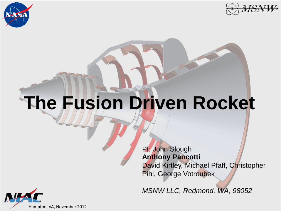
Short trip time
Why We Are Not on Mars Yet?
Reduced IMLEO
High Exit Velocity (Isp)
Takes too long Costs too much
Safety
Bone & muscle loss
Increased risk of critical failure
Radiation exposure Cancer risk
Mental fatigue
Governmental support Public interest
Solution: Political
High 𝐄𝐧𝐠𝐢𝐧𝐞 𝐏𝐨𝐰𝐞𝐫
𝐒𝐩𝐚𝐜𝐞𝐜𝐫𝐚𝐟𝐭 𝐌𝐚𝐬𝐬 (α)
New method of propulsion is needed

Schematic of the inductively driven metal propellant compression of an FRC
plasmoid for propulsion
(a) Thin hoops of metal are driven at the proper angle
and speed for convergence onto target plasmoid at
thruster throat. Target FRC plasmoid is created and
injected into thruster chamber.
(b) Target FRC is confined by axial magnetic field from
shell driver coils as it translates through chamber
eventually stagnating at the thruster throat
(c) Converging shell segments form fusion blanket
compressing target FRC plasmoid to fusion
conditions
(d) Vaporized and ionized by fusion neutrons and
alphas, the plasma blanket expands against the
divergent magnetic field resulting directed flow of
the metal plasma out of the magnetic nozzle.
The Fusion Driven Rocket

Shell (liner) implosion driven by B from large axial currents in shell.
MTF Issues: • Extremely low inductance load difficult to drive
(massively parallel HV caps and switches) • Close proximity and electrical contact major
collateral damage with each pulse • Small FRC must be formed close to implosion
marginal B for ignition w injector destruction • Only inefficient 2D compression possible
requires much larger driver energy
Liner implosion from j x B force between external coil and induced liner currents
FDR Advantages: • Large driver coil easy to power with ample
standoff • Driver electrically isolated from liner and
magnetically from fusion process • Large FRC can be formed external to implosion
with abundant B for ignition • Full 3D compression can be realized for
efficient compression and translation
Magneto-Inertial Fusion Two Approaches
John Slough, David Kirtley, George Votroubek, and Chris Pihl, “Fusion Based on the Inductively-Driven Lithium Liner Compression of an FRC Plasmoid”, 20th ANS TOFE, Aug 2012
Liner Driver System
FRC Injector
Magnetic Nozzle
Foil Liner Compression
FRC plasmoid
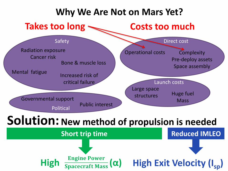
FDR offers the first realistic
approach to fusion-based propulsion
Benefit Result
Direct transfer of fusion
energy to the propellant
High efficiency,
low mass engine
Uses solid propellant No significant tankage
High exhaust velocities
(2000- 5000s Isp)
Short trip time,
high mass fraction
Low IMLEO
Magnetic insulated
reaction chamber and
nozzle
No significant physical interaction
with the spacecraft
Minimal thermal heat load and Low
radiator mass
Low energy requirements
to achieve MIF
Low mass (single launch) and greatly
reduced cost
1
2
3
4
5
• Background
• Benchmarks of FDR program – Mission Architecture Study
– Spacecraft Design
– Theoretical work
• Research Plan – Experiment validation
– Numerical & Analytical Studies
– Spacecraft Design
– Mission Architecture
• Roadmap

FDR Mission Parameters Initial Mission Studies
Fusion Assumptions: • Ionization cost is 75 MJ/kg
• Coupling Efficiency to liner is 50%
• Thrust conversion ηt ~ 90%
• Realistic liner mass are 0.28 kg to 0.41 kg
• Corresponds to a Gain of 50 to 500
• Ignition Factor of 5
• Safety margin of 2: GF =GF(calc.)/2
Mission Assumptions: • Mass of Payload= 61 MT
• Habitat 31 MT
• Aeroshell 16 MT
• Descent System 14 MT
• Specific Mass of capacitors ~ 1 J/g
• Specific Mass of Solar Electric Panels 200 W/kg
• Tankage fraction of 10% (tanks, structure,
radiator, etc.)
• Payload mass fraction =Payload Mass/Initial
Mass
• System Specific Mass = Dry Mass/SEP (kg/kW)
• Analysis for single transit optimal transit to Mars
• Full propulsive braking for Mars Capture - no
aerobraking
Trip Time (Days)
Fusio
n G
ain
20 40 60 80 100 12050
100
150
200
250
300
350
Paylo
d M
ass F
raction
0
0.1
0.2
0.3
0.4
0.5
0.6
0.7
0.8
Higher fusion gain
and longer trip times
result in higher
payload mass fraction
Burn Time (Days)
Tota
l G
ain
20 40 60 80
50
100
150
200
Paylo
d M
ass F
raction
0
0.1
0.2
0.3
0.4
0.5
0.6
0.7
0.8
Burn time of ~10 days
is optimal
Anthony Pancotti, John Slough, David Kirtley, Micheal Pfaff, Christopher Pihl, George Votroubek, “Mission Design Architecture for the Fusion Driven Rocket”, AIAA 48th JPC, July 2012
Pa
ylo
ad
Ma
ss F
raction
P
aylo
ad
Ma
ss F
raction

210 day Round-trip
Manned Mars Mission
61 MT payload
Refuel
Re-crew
For future
missions
(May 19, 2018)
Isp = 5000 s
Power Input= 180 kW
Gain 200
Power(Jet)= 36 MW
Spacecraft Mass = 15 MT
Payload Mass = 61 MT
100 200 3000
2000
4000
6000
8000
Fusion Gain
Isp (
s)
Fusion Equation
15 MT
83 MT 27 MT
134 MT
FDR 1 launch 134 MT
(IMLEO)
210 days
DRA 5.0 (NTP), 9 launches, 848.7 MT IMLEO, 1680 days

Trans-Mars Injection
ΔV 7.3 km/s
ΔT 7.1 days
MI 133.4
Mf 115.0
Earth Orbit Insertion
ΔV 12.0 km/s
ΔT 1.6 days
MI 119.2
MF 15
Trans-Earth
Injection
ΔV 16.5 km/s
ΔT 2.9 days
MI 26.8
Mf 19.2
Mars Orbit Insertion
ΔV 13.2 km/s
ΔT 10.5 days
MI 115.0
Mf 87.8
210 day Round-trip (Mission Details)
0 50 100 150 200 2500
5
10
15x 10
4
Time (Days)M
ass (
Kg)
0 50 100 150 200 2500
10
20
30
40
50
Time (Days)
DeltaV
(km
/s)
FDR
Solar Panels
Crew
Habitat Radiator
Propellant
Payload
Oxygen tanks
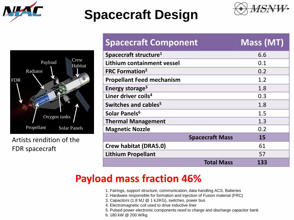
Spacecraft Component Mass (MT) Spacecraft structure1 6.6
Lithium containment vessel 0.1
FRC Formation2 0.2
Propellant Feed mechanism 1.2
Energy storage3 1.8 Liner driver coils4 0.3
Switches and cables5 1.8
Solar Panels6 1.5 Thermal Management 1.3 Magnetic Nozzle 0.2
Spacecraft Mass 15
Crew habitat (DRA5.0) 61
Lithium Propellant 57
Total Mass 133
Spacecraft Design
Artists rendition of the FDR spacecraft
Payload mass fraction 46% 1. Fairings, support structure, communication, data handling ACS, Batteries
2. Hardware responsible for formation and injection of Fusion material (FRC)
3. Capacitors (1.8 MJ @ 1 kJ/KG), switches, power bus
4. Electromagnetic coil used to drive inductive liner
5. Pulsed power electronic components need to charge and discharge capacitor bank
6. 180 kW @ 200 W/kg
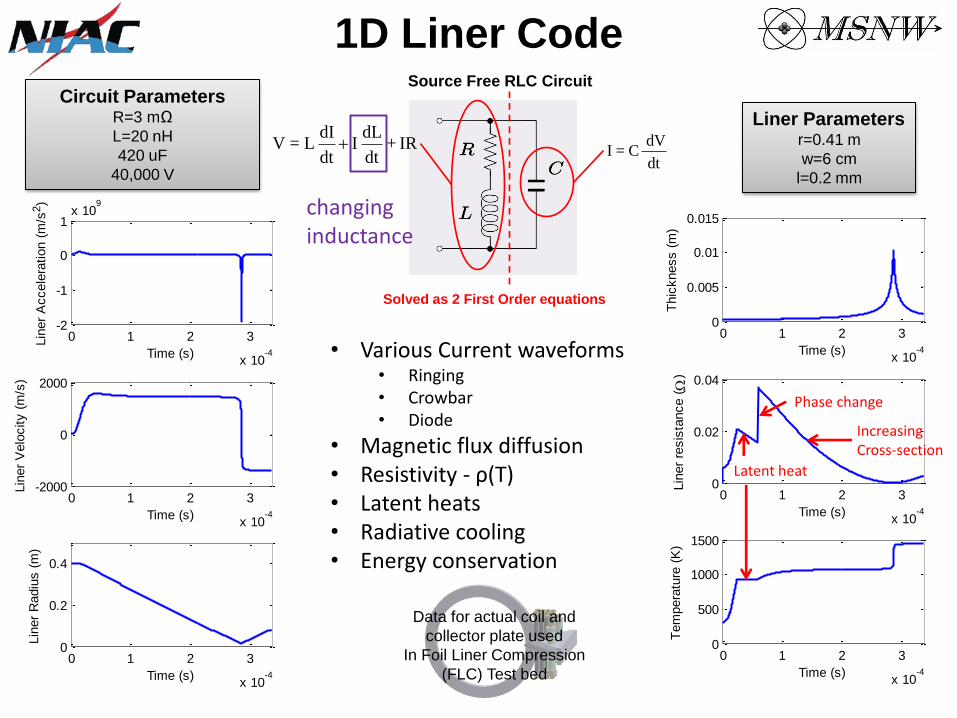
dt
dV C=I
Source Free RLC Circuit
Solved as 2 First Order equations
IR+dt
dL I
dt
dI L=V
1D Liner Code
0 1 2 3
x 10-4
-2
-1
0
1x 10
9
Time (s)
Lin
er
Accele
ration (
m/s
2)
0 1 2 3
x 10-4
-2000
0
2000
Time (s)
Lin
er
Velo
city (
m/s
)
0 1 2 3
x 10-4
0
0.2
0.4
Time (s)
Lin
er
Radiu
s (
m)
0 1 2 3
x 10-4
0
0.005
0.01
0.015
Time (s)
Thic
kness (
m)
0 1 2 3
x 10-4
0
0.02
0.04
Time (s)
Lin
er
resis
tance (
)
0 1 2 3
x 10-4
0
500
1000
1500
Time (s)T
em
pera
ture
(K
)
• Various Current waveforms • Ringing • Crowbar • Diode
• Magnetic flux diffusion • Resistivity - ρ(T) • Latent heats • Radiative cooling • Energy conservation
Data for actual coil and
collector plate used
In Foil Liner Compression
(FLC) Test bed
Circuit Parameters R=3 mΩ
L=20 nH
420 uF
40,000 V
Liner Parameters r=0.41 m
w=6 cm
l=0.2 mm
Latent heat
Increasing Cross-section
Phase change
changing inductance
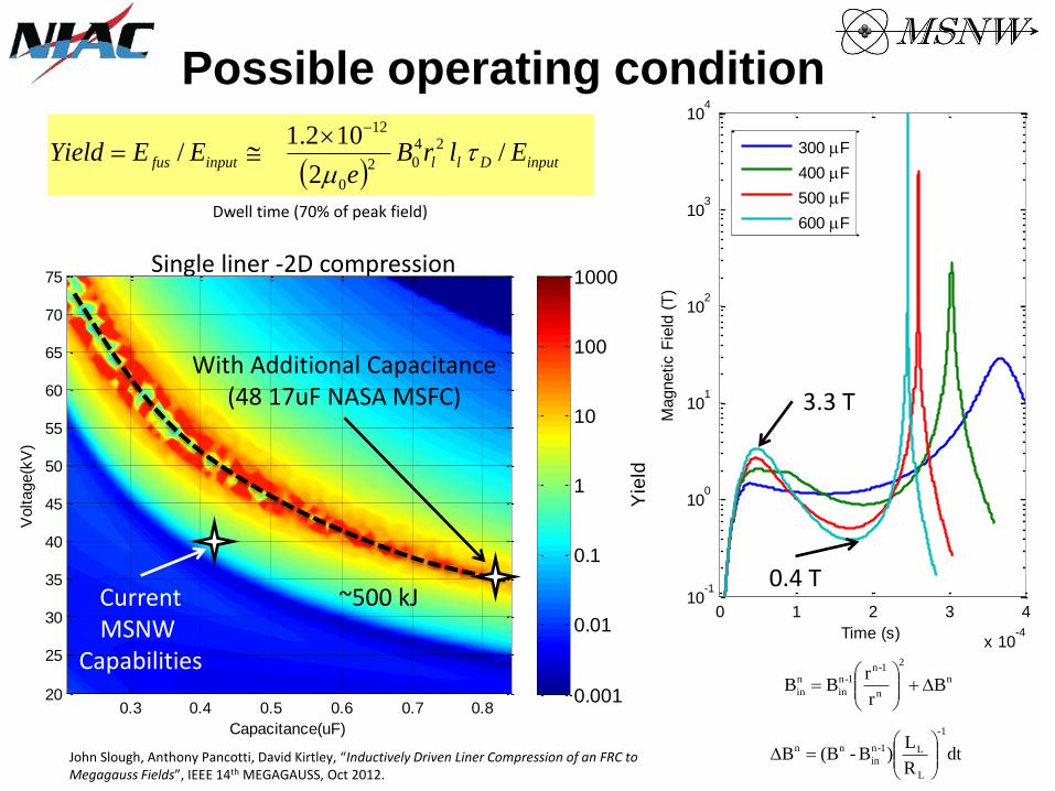
Possible operating condition
inputDllinputfus ElrBe
EEYield /2
102.1/ 24
02
0
12
Dwell time (70% of peak field)
Single liner -2D compression
Capacitance(uF)
Voltage(k
V)
0.3 0.4 0.5 0.6 0.7 0.820
25
30
35
40
45
50
55
60
65
70
75
Yie
ld
0.001
0.01
0.1
1
10
100
1000
Current MSNW
Capabilities
With Additional Capacitance (48 17uF NASA MSFC)
~500 kJ 0 1 2 3 4
x 10-4
10-1
100
101
102
103
104
Time (s)
Magnetic F
ield
(T
)
300 F
400 F
500 F
600 F
3.3 T
0.4 T
dtR
L)B-(BB
-1
L
L1-n
in
nn
n
2
n
1-n1-n
in
n
in Br
rBB
John Slough, Anthony Pancotti, David Kirtley, “Inductively Driven Liner Compression of an FRC to Megagauss Fields”, IEEE 14th MEGAGAUSS, Oct 2012.
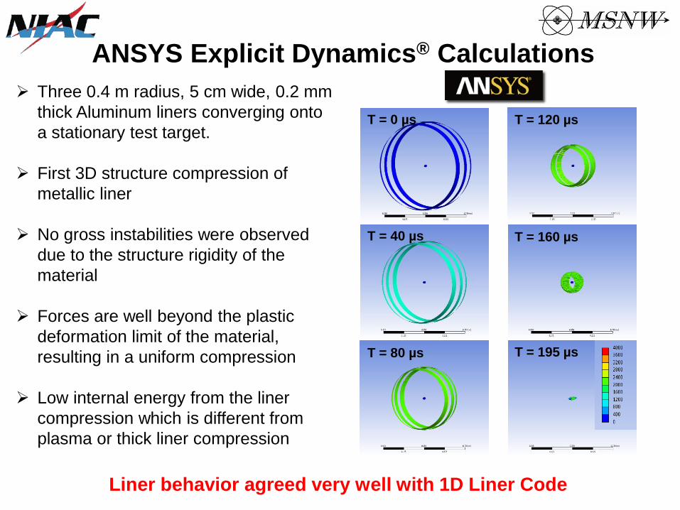
T = 0 µs
T = 40 µs
T = 80 µs
T = 120 µs
T = 160 µs
T = 195 µs
Three 0.4 m radius, 5 cm wide, 0.2 mm
thick Aluminum liners converging onto
a stationary test target.
First 3D structure compression of
metallic liner
No gross instabilities were observed
due to the structure rigidity of the
material
Forces are well beyond the plastic
deformation limit of the material,
resulting in a uniform compression
Low internal energy from the liner
compression which is different from
plasma or thick liner compression
ANSYS Explicit Dynamics® Calculations
Liner behavior agreed very well with 1D Liner Code
• Background
• Benchmarks of FDR program – Mission Architecture Study
– Spacecraft Design
– Theoretical work
• Research Plan – Experiment validation
– Numerical & Analytical Studies
– Spacecraft Design
– Mission Architecture
• Roadmap
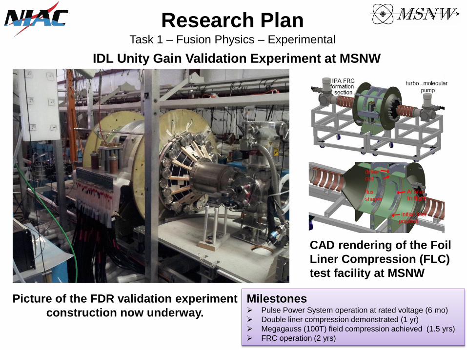
CAD rendering of the Foil
Liner Compression (FLC)
test facility at MSNW
IDL Unity Gain Validation Experiment at MSNW
Picture of the FDR validation experiment
construction now underway.
Research Plan Task 1 – Fusion Physics – Experimental
Milestones Pulse Power System operation at rated voltage (6 mo)
Double liner compression demonstrated (1 yr)
Megagauss (100T) field compression achieved (1.5 yrs)
FRC operation (2 yrs)
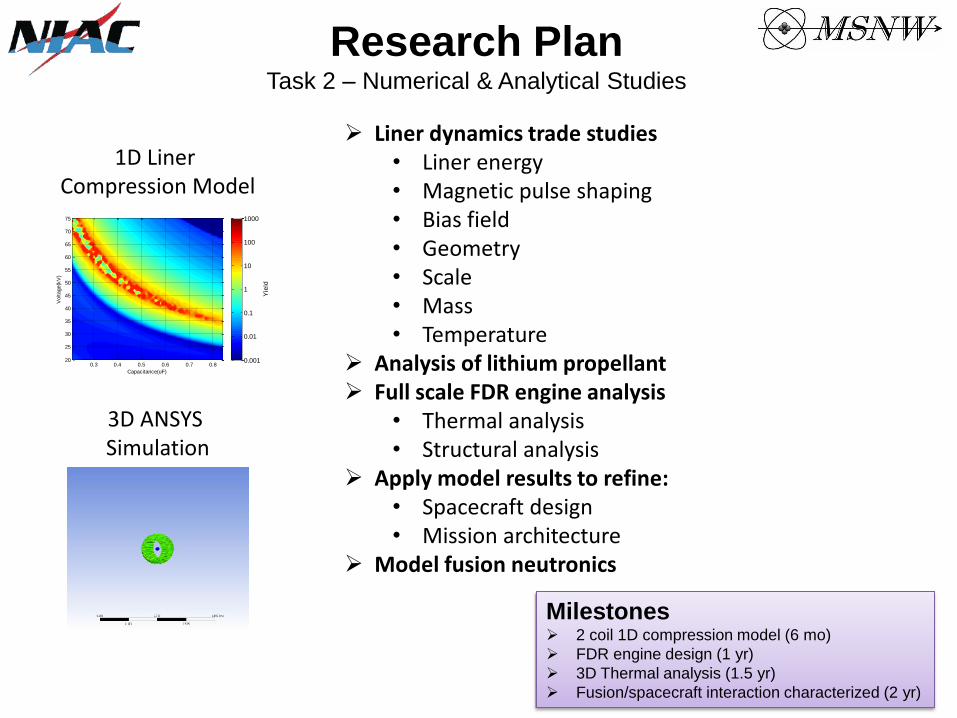
Research Plan Task 2 – Numerical & Analytical Studies
Liner dynamics trade studies • Liner energy • Magnetic pulse shaping • Bias field • Geometry • Scale • Mass • Temperature
Analysis of lithium propellant Full scale FDR engine analysis
• Thermal analysis • Structural analysis
Apply model results to refine: • Spacecraft design • Mission architecture
Model fusion neutronics
1D Liner Compression Model
3D ANSYS Simulation
Milestones 2 coil 1D compression model (6 mo)
FDR engine design (1 yr)
3D Thermal analysis (1.5 yr)
Fusion/spacecraft interaction characterized (2 yr)
Capacitance(uF)
Voltage(k
V)
0.3 0.4 0.5 0.6 0.7 0.820
25
30
35
40
45
50
55
60
65
70
75
Yie
ld
0.001
0.01
0.1
1
10
100
1000
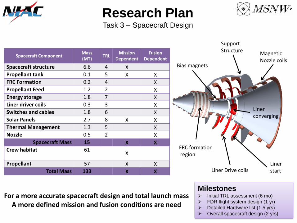
Spacecraft Component Mass (MT)
TRL Mission
Dependent Fusion
Dependent
Spacecraft structure 6.6 4 X
Propellant tank 0.1 5 X X
FRC Formation 0.2 4 X
Propellant Feed 1.2 2 X
Energy storage 1.8 7 X
Liner driver coils 0.3 3 X
Switches and cables 1.8 6 X
Solar Panels 2.7 8 X X
Thermal Management 1.3 5 X
Nozzle 0.5 2 X
Spacecraft Mass 15 X X
Crew habitat 61
X
Propellant 57 X X
Total Mass 133 X X
For a more accurate spacecraft design and total launch mass A more defined mission and fusion conditions are need
Research Plan Task 3 – Spacecraft Design
Milestones Initial TRL assessment (6 mo)
FDR flight system design (1 yr)
Detailed Hardware list (1.5 yrs)
Overall spacecraft design (2 yrs)
Magnetic Nozzle coils
FRC formation region
Support Structure
Bias magnets
Liner Drive coils
Liner converging
Liner start

Research Plan Task 4 – Mission Architecture
Mars
• Single launch to Mars (Sortie)
• Mission refinement
• Long Stay Mission (>500 day)
• Single trip – on orbit assembly
• Larger s/c (fuel launched separate)
• Pre-deploy mission architecture
• Classic DRA style with pre-curser cargo mission
• Ultra-fast (30 day) transfers
Jupiter
• Enter and exit gravity well
• Moon mission
NEO
• Sample return
• Redirection?
Milestones Investigate relevant Mars missions (6 mo)
Incorporate 1D Compression code results (1 yr)
NASA assisted high fidelity mission design (1.5 yr)
DRA report based on FDR (2 yrs)

2015 2020 2025 2030
Phase I Phase II $10 M/year $50 M/year
Gain < 1 RL = 0.4 m
EL = 0.5 kJ
ML = 0.18 kg
D-D Operation
Single Pulse
600 W/kg 300 W/kg 1000 W/kg 180 W/kg
1 kJ/kg 2 kJ/kg
Spaceflight
NIAC Game Changing
Technology Development
Technology
Demonstration
Mission
NASA Mars Flight Program
Manned Mars Spaceflight Program
TR
L
FDR ENGINE (Complete System)
Magnetics
Chamber/Nozzle
FRC Formation
Propellant
Shielding
Thermal
Charging
Energy Storage
Solar Power
Gain > 5 RL = 0.4 m
EL = 2 MJ
ML = 0.38 kg
D-T Operation
Rep Rate > 0.01 Hz
Li Liner
Al Liner
Rep Rate > 0.01 Hz
Gain of 40 RL = 1 m
EL = 3.5 MJ
Rep Rate > 0.1 Hz
Thruster with Nozzle
Gain of 200
Milestones
Concept Validation Experiments
Subscale Ground Demonstration
Full-Scale Ground Prototype
In-Space Demonstration Mission
Manned Mars Mission
Research Plan Technology Roadmap for the Fusion Driven Rocket