The Fundamentals of Camera and Image Sensor Technology · The Fundamentals of Camera and Image...
157
The Fundamentals of Camera and Image Sensor Technology Jon Chouinard Sales Manager, Eastern Region Baumer Ltd.
Transcript of The Fundamentals of Camera and Image Sensor Technology · The Fundamentals of Camera and Image...
The Fundamentals of Camera and Image Sensor Technology
Jon Chouinard Sales Manager, Eastern Region
Baumer Ltd.
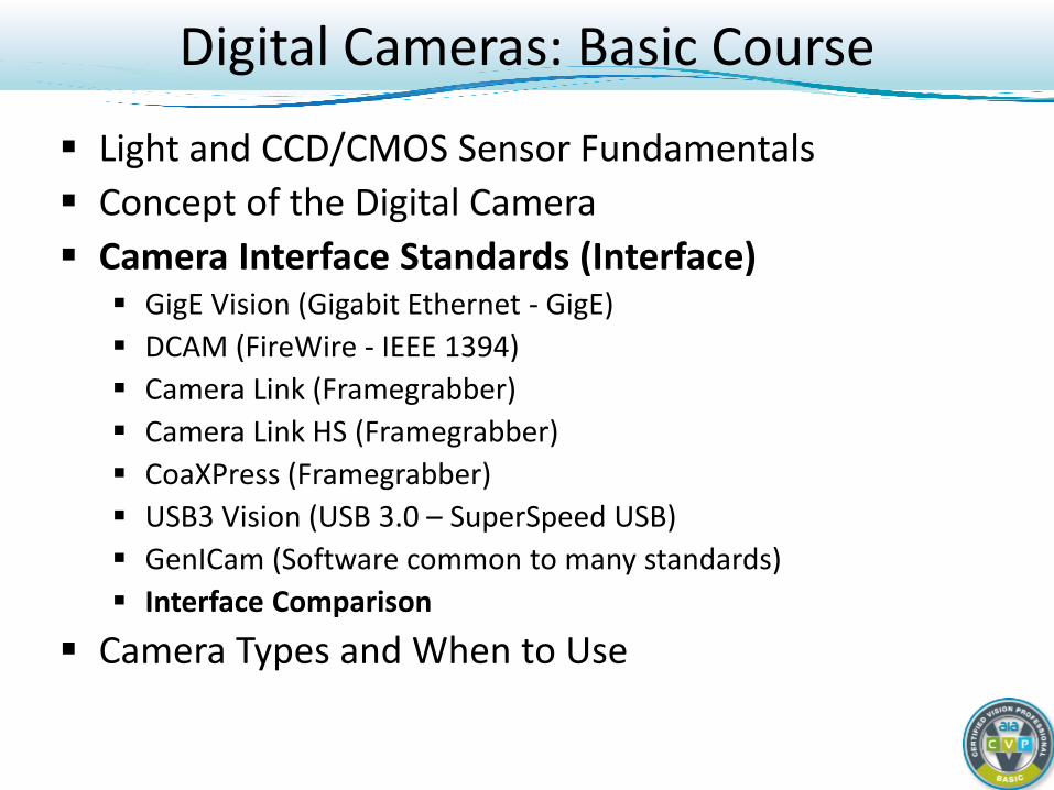
Digital Cameras: Basic Course
Light Basics + CCD/CMOS Imager Fundamentals Digital Camera Principals Interfaces Camera Types and When to Use
Light and CCD/CMOS Sensor Fundamentals
Light Basics CCD and CMOS Sensors
Digital Camera Principals Camera Interface Standards Camera Types and When to Use
Digital Cameras: Basic Course
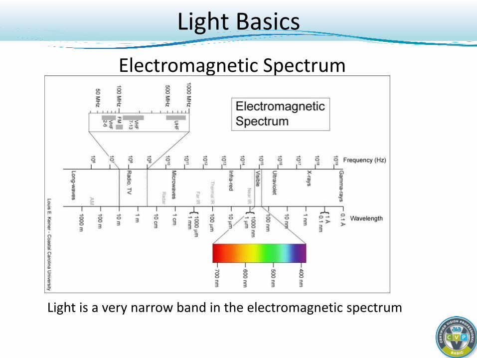
Electromagnetic Spectrum
Light is a very narrow band in the electromagnetic spectrum
Light Basics
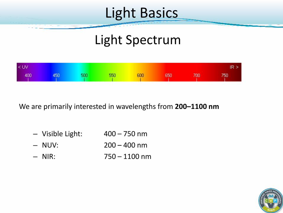
Light Spectrum
We are primarily interested in wavelengths from 200–1100 nm
– Visible Light: 400 – 750 nm – NUV: 200 – 400 nm – NIR: 750 – 1100 nm
Light Basics
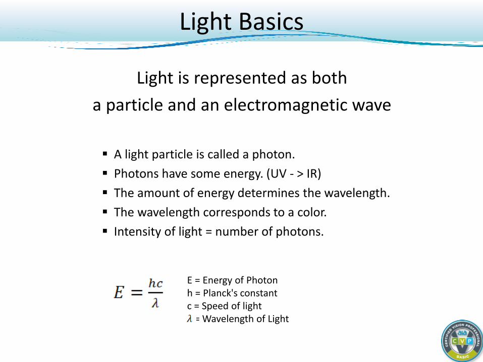
Light is represented as both a particle and an electromagnetic wave
A light particle is called a photon. Photons have some energy. (UV - > IR) The amount of energy determines the wavelength. The wavelength corresponds to a color. Intensity of light = number of photons.
Light Basics
E = Energy of Photon h = Planck's constant c = Speed of light = Wavelength of Light
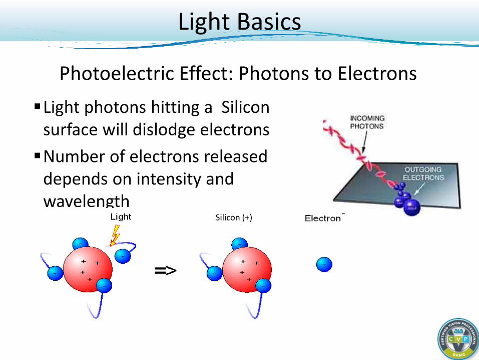
Photoelectric Effect: Photons to Electrons Light photons hitting a Silicon
surface will dislodge electrons Number of electrons released
depends on intensity and wavelength
Silicon (+)
Light Basics
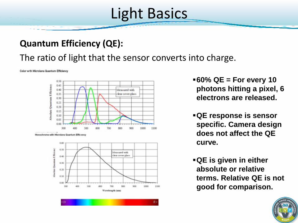
Quantum Efficiency (QE): The ratio of light that the sensor converts into charge.
60% QE = For every 10 photons hitting a pixel, 6 electrons are released. QE response is sensor specific. Camera design does not affect the QE curve. QE is given in either absolute or relative terms. Relative QE is not good for comparison.
Light Basics
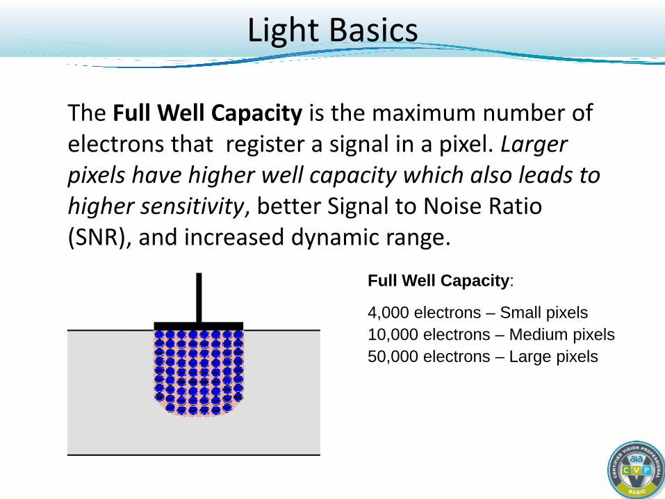
The Full Well Capacity is the maximum number of electrons that register a signal in a pixel. Larger pixels have higher well capacity which also leads to higher sensitivity, better Signal to Noise Ratio (SNR), and increased dynamic range.
Full Well Capacity:
4,000 electrons – Small pixels 10,000 electrons – Medium pixels 50,000 electrons – Large pixels
Light Basics
Digital Cameras: Basic Course Light and CCD/CMOS Sensor Fundamentals
Light Basics CCD and CMOS Sensors
Digital Camera Principals Interfaces Camera Types and When to Use
CCD and CMOS Sensors
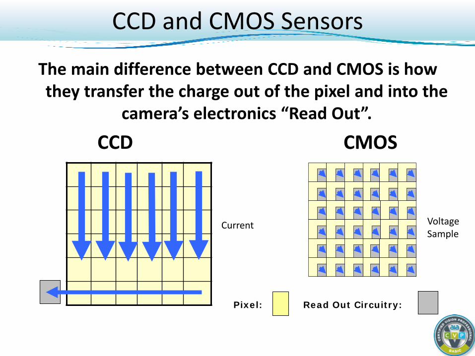
The main difference between CCD and CMOS is how they transfer the charge out of the pixel and into the
camera’s electronics “Read Out”.
CCD CMOS
Pixel: Read Out Circuitry:
Current Voltage Sample
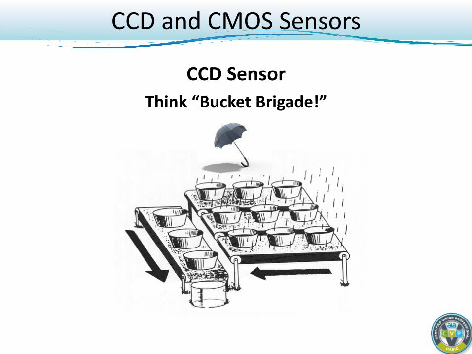
CCD Sensor Think “Bucket Brigade!”
CCD and CMOS Sensors
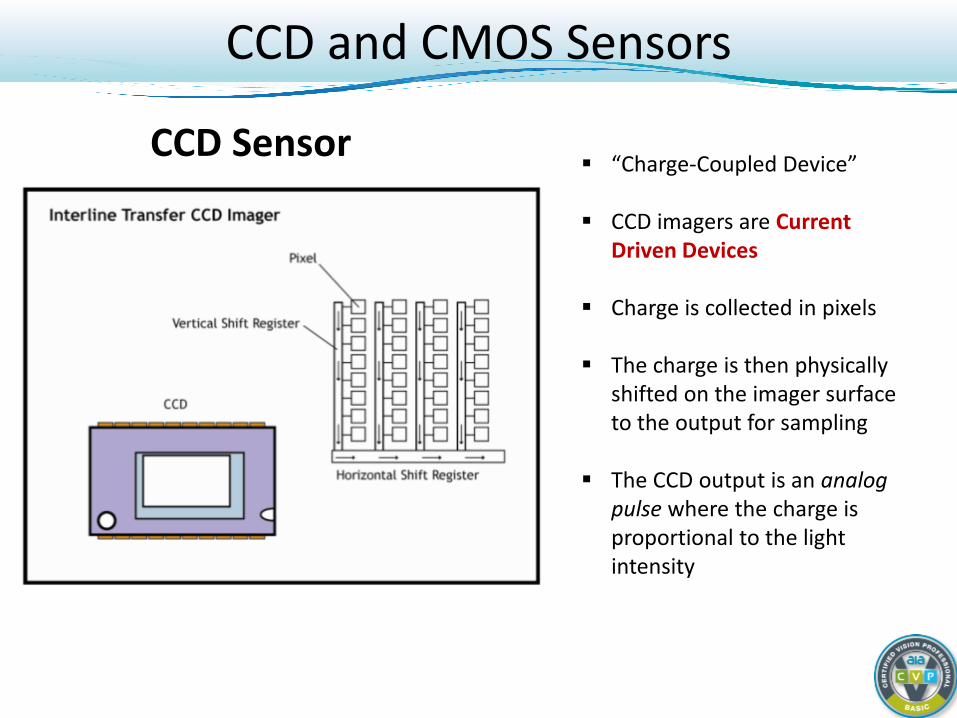
CCD Sensor “Charge-Coupled Device”
CCD imagers are Current
Driven Devices
Charge is collected in pixels
The charge is then physically shifted on the imager surface to the output for sampling
The CCD output is an analog pulse where the charge is proportional to the light intensity
CCD and CMOS Sensors
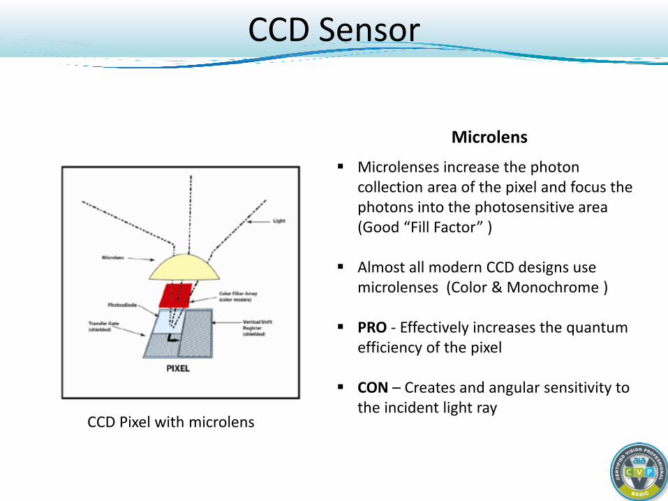
Microlens
Microlenses increase the photon collection area of the pixel and focus the photons into the photosensitive area (Good “Fill Factor” )
Almost all modern CCD designs use microlenses (Color & Monochrome )
PRO - Effectively increases the quantum efficiency of the pixel
CON – Creates and angular sensitivity to the incident light ray
CCD Pixel with microlens
CCD Sensor
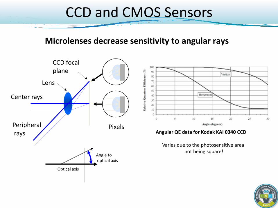
CCD focal plane
Center rays
Peripheral rays
Lens
Pixels
Optical axis
Angle to optical axis
Microlenses decrease sensitivity to angular rays
Angular QE data for Kodak KAI 0340 CCD
Varies due to the photosensitive area not being square!
CCD and CMOS Sensors
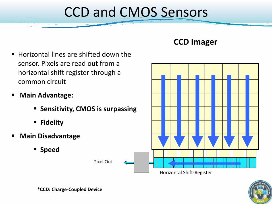
Pixel Out
Horizontal Shift-Register
Horizontal lines are shifted down the sensor. Pixels are read out from a horizontal shift register through a common circuit
Main Advantage:
Sensitivity, CMOS is surpassing
Fidelity
Main Disadvantage
Speed
*CCD: Charge-Coupled Device
CCD Imager
CCD and CMOS Sensors
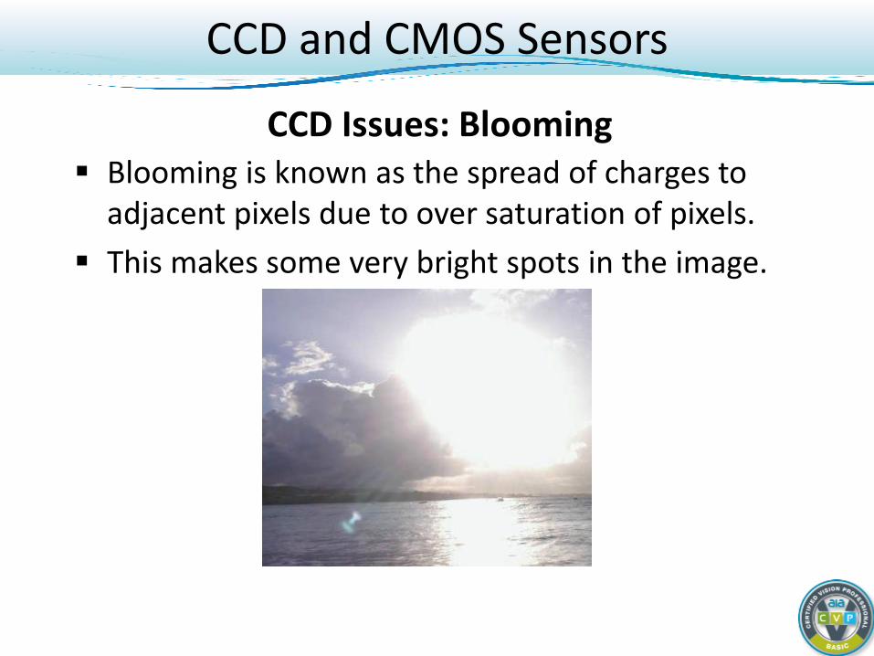
Blooming is known as the spread of charges to adjacent pixels due to over saturation of pixels.
This makes some very bright spots in the image.
CCD Issues: Blooming
CCD and CMOS Sensors
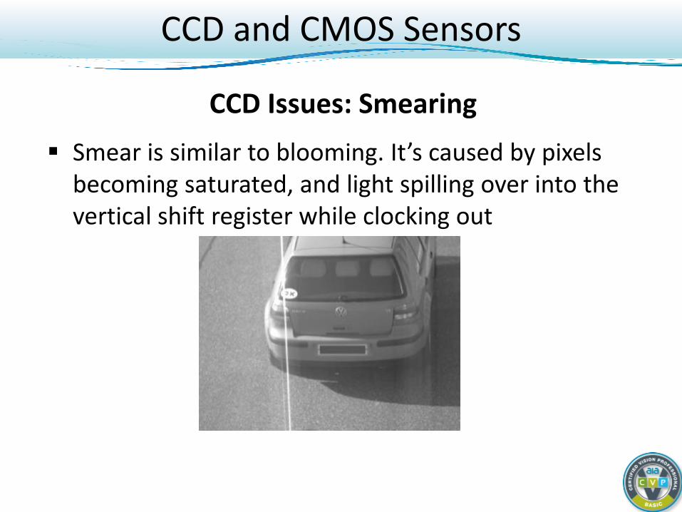
Smear is similar to blooming. It’s caused by pixels becoming saturated, and light spilling over into the vertical shift register while clocking out
CCD Issues: Smearing
CCD and CMOS Sensors
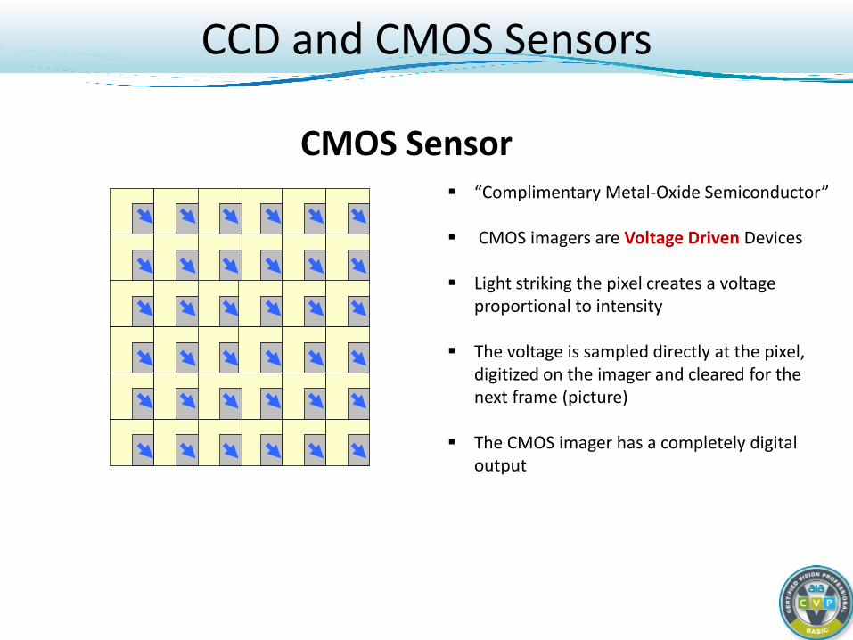
CMOS Sensor “Complimentary Metal-Oxide Semiconductor”
CMOS imagers are Voltage Driven Devices
Light striking the pixel creates a voltage
proportional to intensity
The voltage is sampled directly at the pixel, digitized on the imager and cleared for the next frame (picture)
The CMOS imager has a completely digital output
CCD and CMOS Sensors

CMOS layer stack up prevents using microlens and has lower charge conversion than CCD, usually resulting in lower sensitivity.
Higher Image non uniformities (aka “Fixed Pattern Noise“) due to unevenness between the individual Pixel cells and multiple A/D circuits in column readout.
CMOS is more resistant to Smearing or Blooming than a CCD!
CMOS Issues: Pattern Noise + Sensitivity
CCD and CMOS Sensors
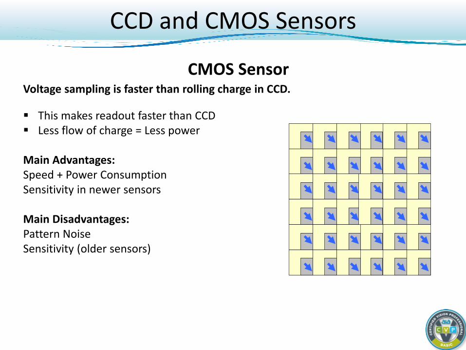
Voltage sampling is faster than rolling charge in CCD.
This makes readout faster than CCD Less flow of charge = Less power
Main Advantages: Speed + Power Consumption Sensitivity in newer sensors Main Disadvantages: Pattern Noise Sensitivity (older sensors)
CMOS Sensor
CCD and CMOS Sensors
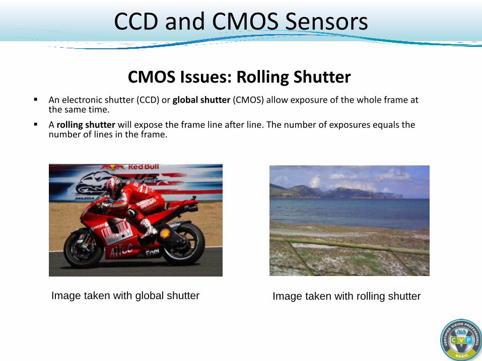
An electronic shutter (CCD) or global shutter (CMOS) allow exposure of the whole frame at the same time.
A rolling shutter will expose the frame line after line. The number of exposures equals the number of lines in the frame.
CMOS Issues: Rolling Shutter
Image taken with global shutter Image taken with rolling shutter
CCD and CMOS Sensors
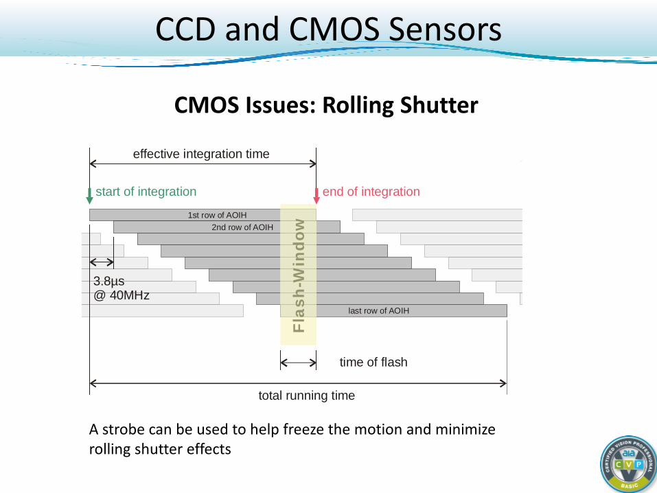
total running time
1st row of AOIH2nd row of AOIH
last row of AOIH
start of integration end of integration
effective integration time
3.8µs@ 40MHz
Flas
h-W
indo
w
time of flash
CMOS Issues: Rolling Shutter
A strobe can be used to help freeze the motion and minimize rolling shutter effects
CCD and CMOS Sensors
Move
Move
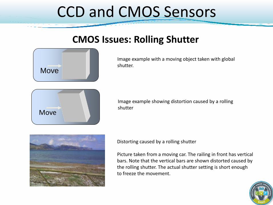
Distorting caused by a rolling shutter Picture taken from a moving car. The railing in front has vertical bars. Note that the vertical bars are shown distorted caused by the rolling shutter. The actual shutter setting is short enough to freeze the movement.
Image example showing distortion caused by a rolling shutter
Image example with a moving object taken with global shutter.
CMOS Issues: Rolling Shutter
CCD and CMOS Sensors
Progressive and Interlaced Scanning Image from camera is formed by sequence of pixel lines scanned
and displayed in one of two different ways. Progressive scanning :
Scanning of first line, second line, third line, etc… until the entire frame is scanned.
Interlaced scanning : Scanning of odd-numbered lines, then scanning of even-numbered
lines. Both fields are then combined to form the entire frame. Found in analog cameras
CCD and CMOS Sensors
Field 2 Field 1
1
3
5
7
9
11
2
4
6
8
10
12
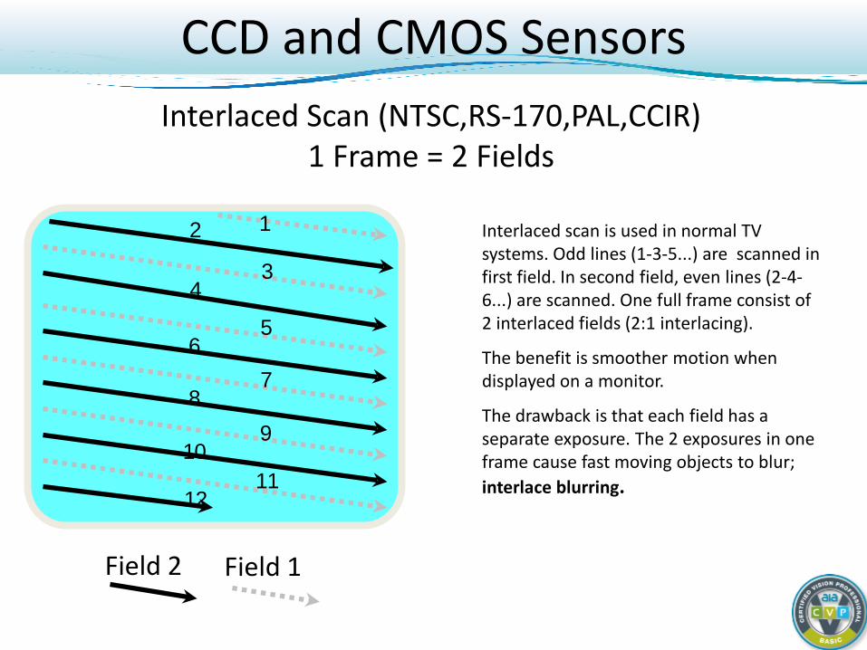
Interlaced scan is used in normal TV systems. Odd lines (1-3-5...) are scanned in first field. In second field, even lines (2-4-6...) are scanned. One full frame consist of 2 interlaced fields (2:1 interlacing).
The benefit is smoother motion when displayed on a monitor.
The drawback is that each field has a separate exposure. The 2 exposures in one frame cause fast moving objects to blur; interlace blurring.
Interlaced Scan (NTSC,RS-170,PAL,CCIR) 1 Frame = 2 Fields
CCD and CMOS Sensors

Interlace Blurring
CCD and CMOS Sensors
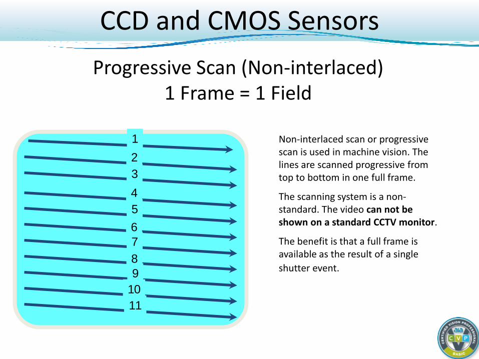
Progressive Scan (Non-interlaced) 1 Frame = 1 Field
Non-interlaced scan or progressive scan is used in machine vision. The lines are scanned progressive from top to bottom in one full frame.
The scanning system is a non-standard. The video can not be shown on a standard CCTV monitor.
The benefit is that a full frame is available as the result of a single shutter event.
1
3
5
7
9
11
2
4
6
8
10
CCD and CMOS Sensors
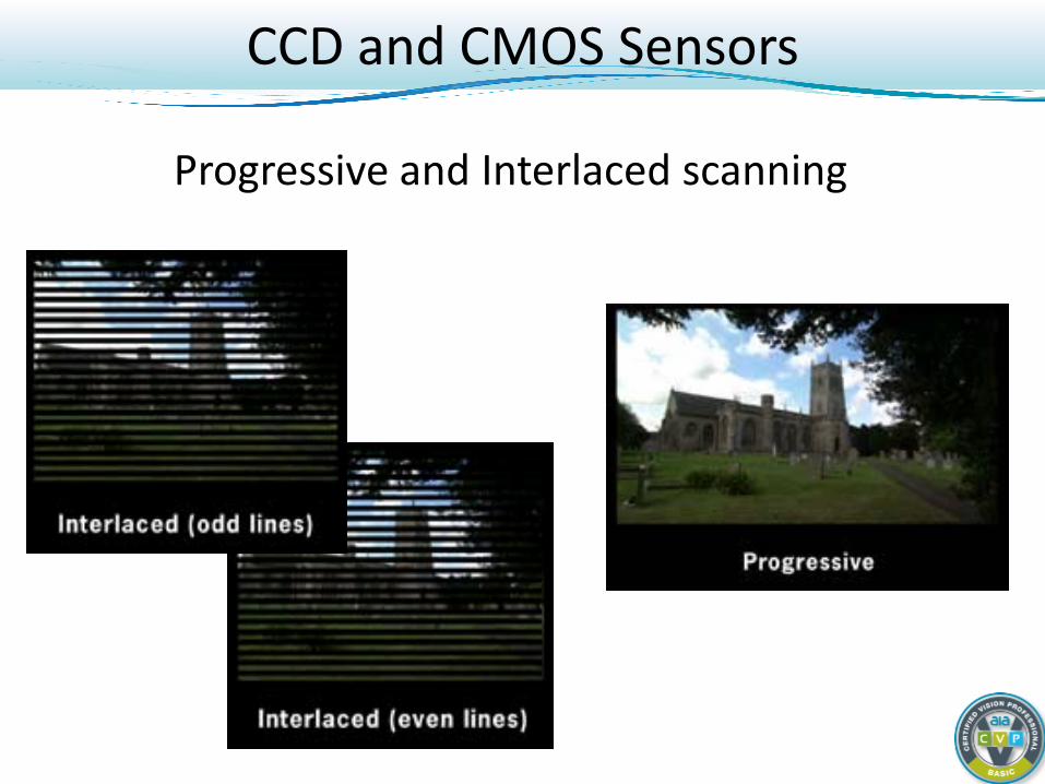
Progressive and Interlaced scanning
CCD and CMOS Sensors
Progressive and Interlaced scanning Interlaced scanning:
Spatial resolution is reduced but temporal resolution is improved. Twice as many ‘full’ images are presented per second.
Progressive scanning: Sharper images are formed No interlaced blurring!
Note: With interlaced, you’ll see smoother motion with same frame rate, but will also notice the interlaced lines in the image.
CCD and CMOS Sensors
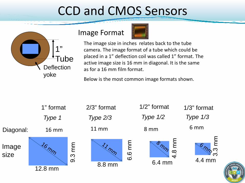
Image Format
1” format 1/2” format 2/3” format 1/3” format
12.8 mm 8.8 mm 6.4 mm 4.4 mm
16 mm 11 mm 8 mm 6 mm
1” Tube
Deflection yoke
The image size in inches relates back to the tube camera. The image format of a tube which could be placed in a 1” deflection coil was called 1” format. The active image size is 16 mm in diagonal. It is the same as for a 16 mm film format.
Below is the most common image formats shown.
Diagonal:
Type 1 Type 1/2 Type 2/3 Type 1/3
Image size
CCD and CMOS Sensors
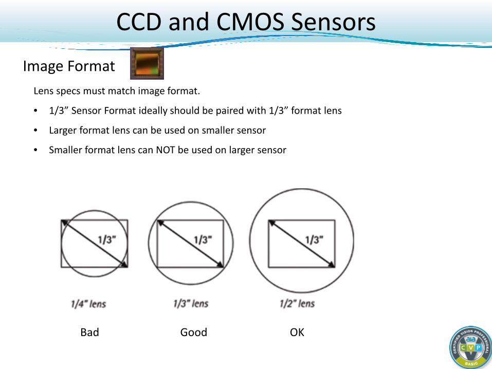
Image Format Lens specs must match image format.
• 1/3” Sensor Format ideally should be paired with 1/3” format lens
• Larger format lens can be used on smaller sensor
• Smaller format lens can NOT be used on larger sensor
CCD and CMOS Sensors
Good Bad OK
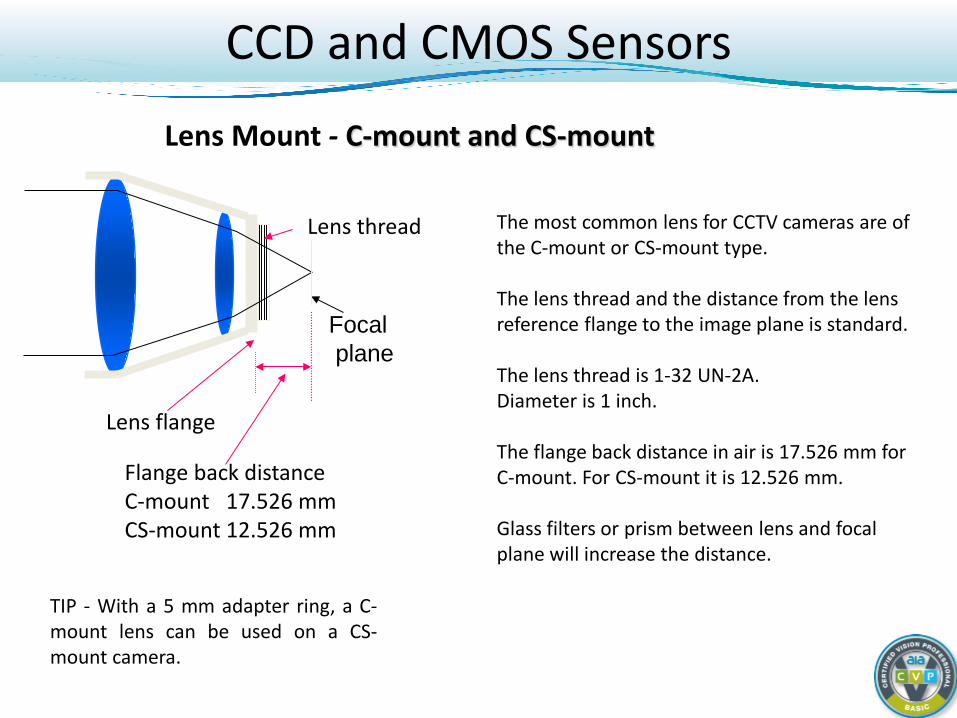
Lens Mount - C-mount and CS-mount
Focal plane
Flange back distance C-mount 17.526 mm CS-mount 12.526 mm
Lens flange
Lens thread The most common lens for CCTV cameras are of the C-mount or CS-mount type. The lens thread and the distance from the lens reference flange to the image plane is standard. The lens thread is 1-32 UN-2A. Diameter is 1 inch. The flange back distance in air is 17.526 mm for C-mount. For CS-mount it is 12.526 mm. Glass filters or prism between lens and focal plane will increase the distance.
TIP - With a 5 mm adapter ring, a C-mount lens can be used on a CS-mount camera.
CCD and CMOS Sensors
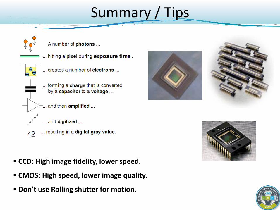
Summary / Tips
CCD: High image fidelity, lower speed.
CMOS: High speed, lower image quality.
Don’t use Rolling shutter for motion.
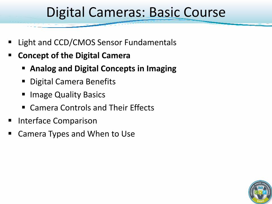
Digital Cameras: Basic Course
Light and CCD/CMOS Sensor Fundamentals Concept of the Digital Camera Analog and Digital Concepts in Imaging Digital Camera Benefits Image Quality Basics Camera Controls and Their Effects
Interface Comparison Camera Types and When to Use
Analog and Digital Concepts
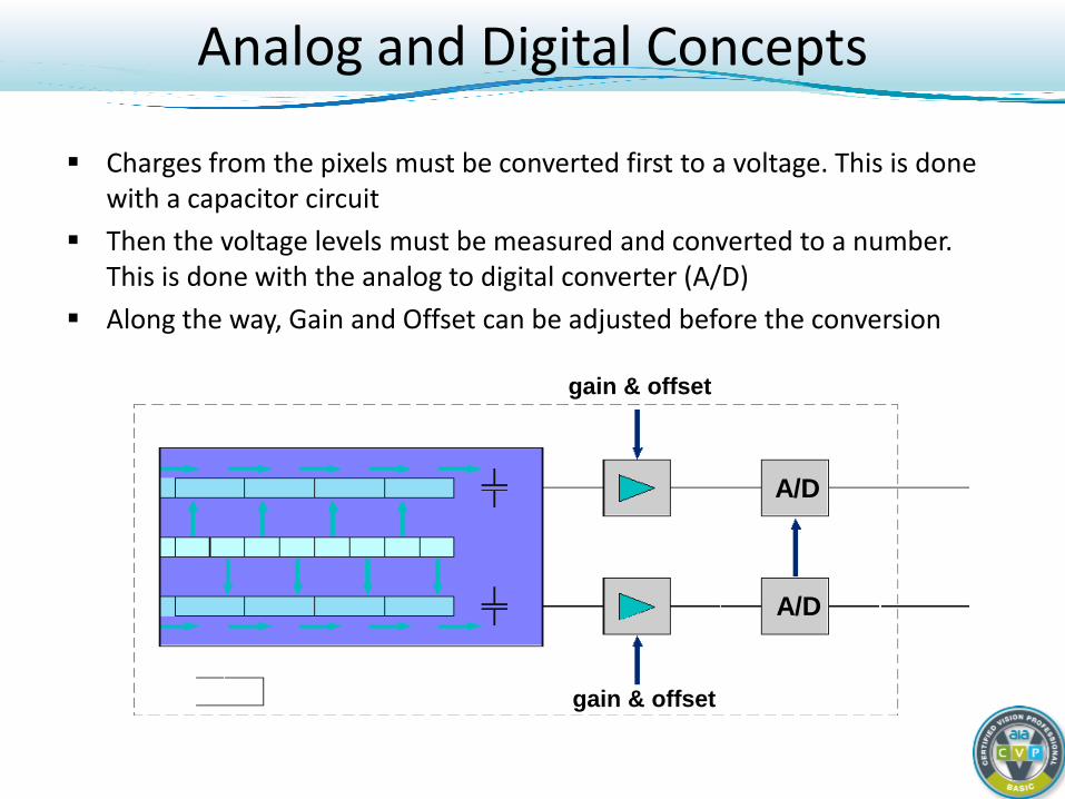
Charges from the pixels must be converted first to a voltage. This is done with a capacitor circuit
Then the voltage levels must be measured and converted to a number. This is done with the analog to digital converter (A/D)
Along the way, Gain and Offset can be adjusted before the conversion
gain & offset
gain & offset
A/D
A/D
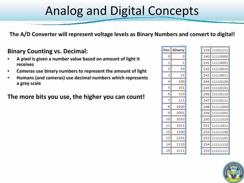
Binary Counting vs. Decimal: • A pixel is given a number value based on amount of light it
receives • Cameras use binary numbers to represent the amount of light • Humans (and cameras) use decimal numbers which represents
a grey scale
The more bits you use, the higher you can count!
The A/D Converter will represent voltage levels as Binary Numbers and convert to digital!
Analog and Digital Concepts
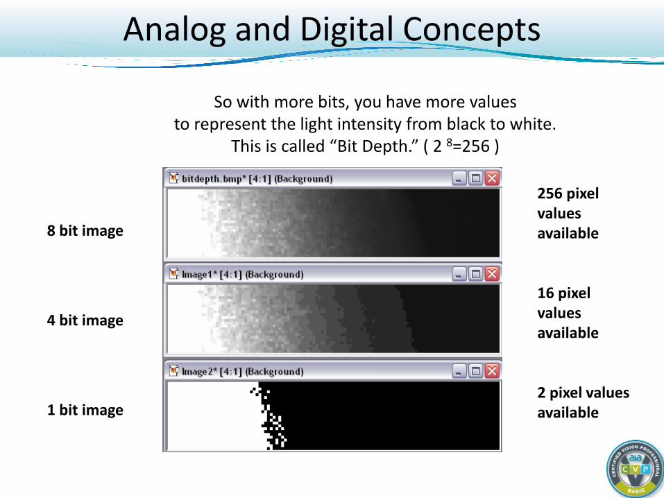
So with more bits, you have more values to represent the light intensity from black to white.
This is called “Bit Depth.” ( 2 8=256 )
8 bit image
4 bit image
1 bit image
256 pixel values available
16 pixel values available
2 pixel values available
Analog and Digital Concepts
High Bit Depth Considerations With more bits, you get a more accurate
measurement of the light. (8, 10, 12 bits = 256, 1024, 4096 grey scales)
With more bits, you also have more data to transfer, process, store (12 bit = 50% more data more than 8 bit).
Analog and Digital Concepts
Digital Cameras: Basic Course
Light and CCD/CMOS Sensor Fundamentals Concept of the Digital Camera Analog and Digital Concepts in Imaging Digital Camera Benefits Image Quality Basics Camera Controls and Their Effects
Interface Comparison Camera Types and When to Use
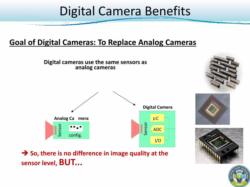
Digital Camera Benefits
Digital cameras use the same sensors as analog cameras
So, there is no difference in image quality at the sensor level, BUT...
ADC
Sens
or
Digital Camera
µ C
I/O
Analog Ca mera
Sens
or
config.
Goal of Digital Cameras: To Replace Analog Cameras
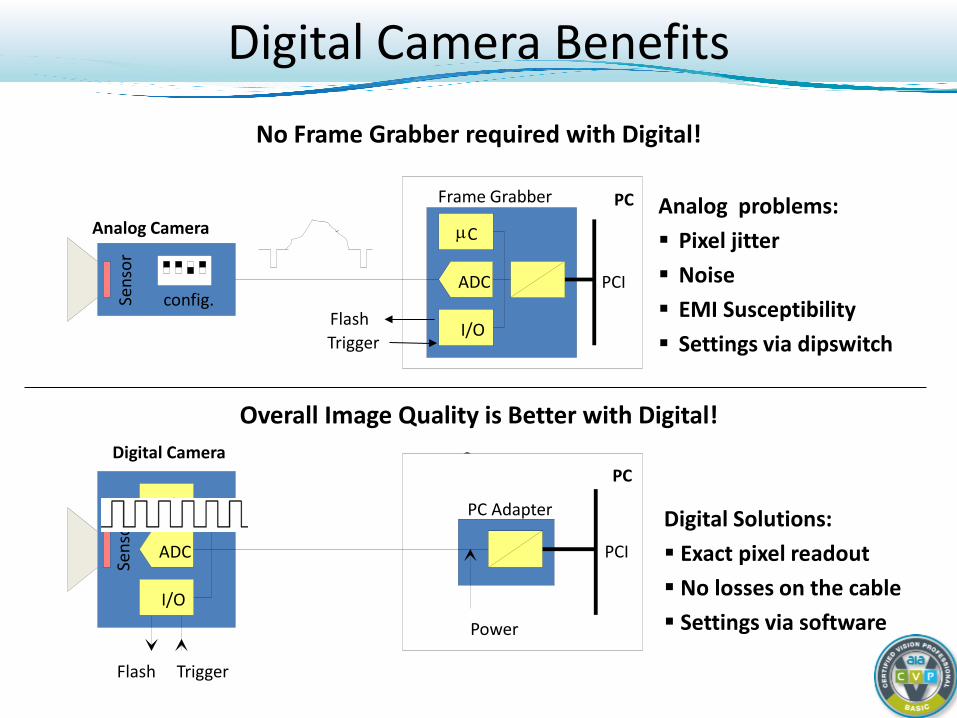
No Frame Grabber required with Digital!
Overall Image Quality is Better with Digital!
• ADC
Sens
or
Digital Camera
µ C
I/O
Trigger Flash
PCI
PC Adapter
Power
PC
Analog Camera
Trigger Flash
Frame Grabber PC
PCI ADC
µ C
I/O
Sens
or
config.
Analog problems: Pixel jitter Noise EMI Susceptibility Settings via dipswitch
Digital Solutions: Exact pixel readout No losses on the cable Settings via software
Digital Camera Benefits
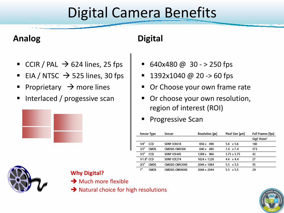
Analog CCIR / PAL 624 lines, 25 fps EIA / NTSC 525 lines, 30 fps Proprietary more lines Interlaced / progessive scan
Digital 640x480 @ 30 - > 250 fps 1392x1040 @ 20 -> 60 fps Or Choose your own frame rate Or choose your own resolution,
region of interest (ROI) Progressive Scan
Why Digital? Much more flexible Natural choice for high resolutions
Digital Camera Benefits
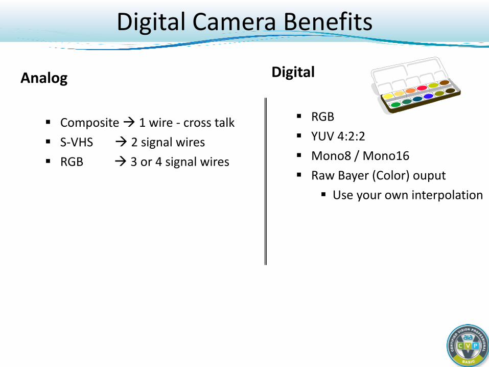
Analog Composite 1 wire - cross talk S-VHS 2 signal wires RGB 3 or 4 signal wires
Digital RGB YUV 4:2:2 Mono8 / Mono16 Raw Bayer (Color) ouput
Use your own interpolation
Digital Camera Benefits
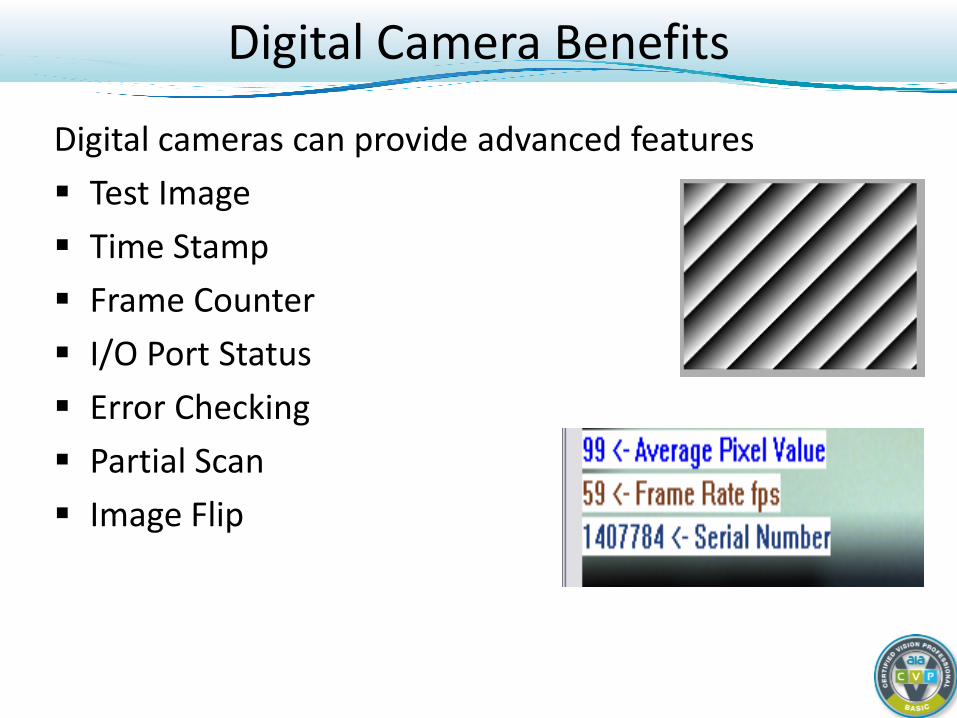
Digital cameras can provide advanced features Test Image Time Stamp Frame Counter I/O Port Status Error Checking Partial Scan Image Flip
Digital Camera Benefits
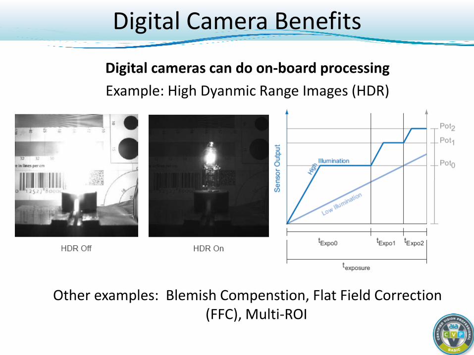
Digital cameras can do on-board processing Example: High Dyanmic Range Images (HDR)
Other examples: Blemish Compenstion, Flat Field Correction (FFC), Multi-ROI
Digital Camera Benefits
Digital Cameras: Basic Course
Light and CCD/CMOS Sensor Fundamentals Concept of the Digital Camera Analog and Digital Concepts in Imaging Digital Camera Benefits Image Quality Basics Camera Controls and Their Effects
Interface Comparison Camera Types and When to Use
Image Quality Basics
Temporal Noise:
Anything besides light that causes a pixel’s value to change over time (temperature, ADC errors, etc.). This is measured by EMVA 1288
Spatial Noise:
“Fixed Pattern Noise.” Constant non-uniformities in the image caused by bad sensor design, electrical noise, etc.
Image Quality Basics
Some Sources of Temporal Noise: Shot Noise / Photon Noise:
Due to random fluctuations in the light. [Brighter/Better Light = less shot noise]
Dark Current Noise: The rate at which electrons are produced due to thermal effects. Every 8°C = Dark noise doubles. [cooler camera = less dark noise]
Quantization Noise: Errors coming from the A/D conversion process [Use a better ADC = less quantization noise]
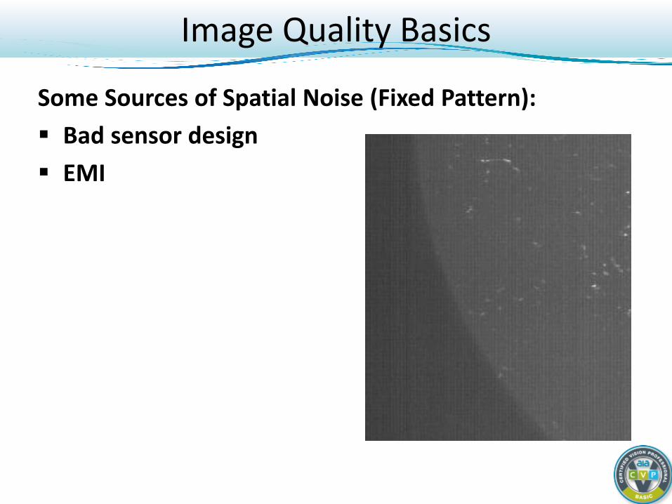
Image Quality Basics
Some Sources of Spatial Noise (Fixed Pattern): Bad sensor design EMI
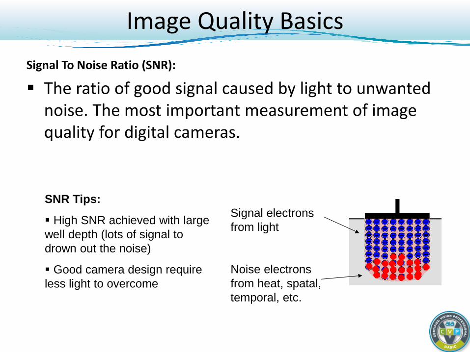
Image Quality Basics Signal To Noise Ratio (SNR):
The ratio of good signal caused by light to unwanted noise. The most important measurement of image quality for digital cameras.
Signal electrons from light
Noise electrons from heat, spatal, temporal, etc.
SNR Tips:
High SNR achieved with large well depth (lots of signal to drown out the noise)
Good camera design require less light to overcome
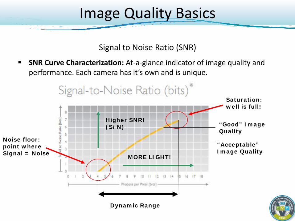
Signal to Noise Ratio (SNR)
SNR Curve Characterization: At-a-glance indicator of image quality and performance. Each camera has it’s own and is unique.
Saturation: well is full!
Noise floor: point where Signal = Noise MORE LIGHT!
Higher SNR! (S/N)
Dynamic Range
“Acceptable” Image Quality
“Good” Image Quality
Image Quality Basics
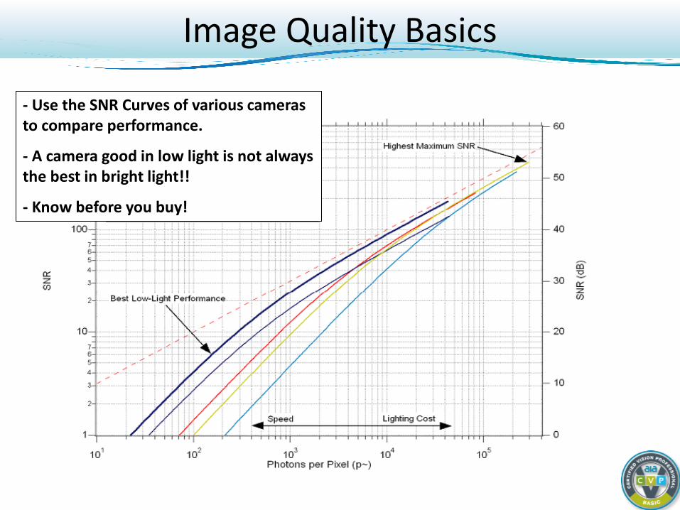
- Use the SNR Curves of various cameras to compare performance.
- A camera good in low light is not always the best in bright light!!
- Know before you buy!
Image Quality Basics
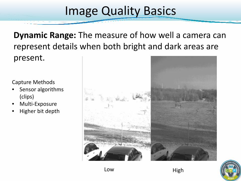
Image Quality Basics
Dynamic Range: The measure of how well a camera can represent details when both bright and dark areas are present.
Low High
Capture Methods • Sensor algorithms
(clips) • Multi-Exposure • Higher bit depth
Image Quality Basics
EMVA1288: Industry standard for measuring image quality of digital cameras.
Testing uses known set of conditions (light, lens, targets, etc.). Manufacturers’ report data in agreed-upon format. Results for multiple cameras published to show level of
consistency. Allows customer to compare apples to apples. http://www.standard1288.org/
Digital Cameras: Basic Course
Light and CCD/CMOS Sensor Fundamentals Concept of the Digital Camera Analog and Digital Concepts in Imaging Digital Camera Benefits Image Quality Basics Camera Controls and Their Effects
Interface Comparison Camera Types and When to Use
Camera Controls
What are some camera controls can we use to affect image quality?
Gain Exposure Brightness (black level) Image Format Resolution (Array Size)
Camera Controls
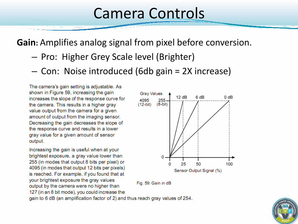
Gain: Amplifies analog signal from pixel before conversion. – Pro: Higher Grey Scale level (Brighter) – Con: Noise introduced (6db gain = 2X increase)
Camera Controls
Gain Considerations:
Increasing gain will increase visibility of both signal and noise!
Does not increase image quality! Use only as a last resort to increase brightness. Gain may be limited at higher bit depths.
Camera Controls
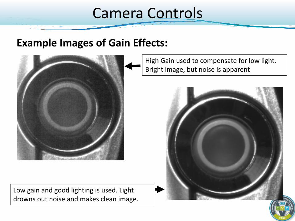
Example Images of Gain Effects: High Gain used to compensate for low light.
Bright image, but noise is apparent
Low gain and good lighting is used. Light drowns out noise and makes clean image.
Camera Controls
Exposure Time: The length of time that the sensor is open for collecting light. Also known as shutter speed and integration time. Exposure Time Considerations: Frame rate may be reduced with increase. Motion blur is greater with increase. SNR is greatly increased with more exposure (longer
shutter time – filling pixel well)
Camera Controls
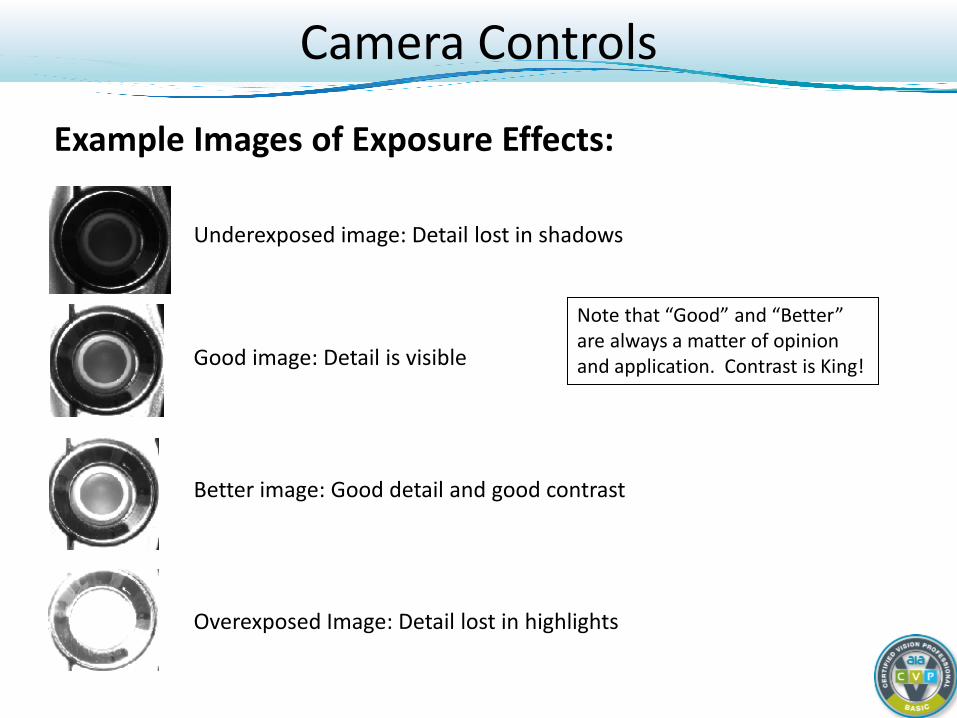
Example Images of Exposure Effects:
Underexposed image: Detail lost in shadows
Good image: Detail is visible
Better image: Good detail and good contrast
Overexposed Image: Detail lost in highlights
Note that “Good” and “Better” are always a matter of opinion and application. Contrast is King!
Camera Controls Black Level (Brightness): Adds an offset to pixel values. Adjusting the camera’s black level will result in an offset to the pixel values output by the camera. Increasing the black level setting will result in a positive offset in the digital values output for the pixels. Decreasing the black level setting will result in a negative offset in the digital values output for the pixels. • i.e. Black image emitting photons – adjust black level to
capture or not Black Level Considerations: Proper use is to ensure camera accurately measures light
when scene is darker. Side effect is that it can make the image brighter or darker, but
not by much.
Camera Controls
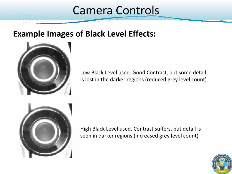
Example Images of Black Level Effects:
High Black Level used. Contrast suffers, but detail is seen in darker regions (increased grey level count)
Low Black Level used. Good Contrast, but some detail is lost in the darker regions (reduced grey level count)
Camera Controls Image Format: The type of image sent from the camera. Usually specified by color or mono, and then by bit depth. (i.e. mono8) Image Format Considerations: Higher bit depth = more data to transmit/process. Lower bit depth = loss of detail Be wary of anyone wishing to “view” a 12 bit image on a computer
monitor. All monitors can only display 8 bits or less! Many people think they need 12 bits but don’t!
Camera Controls
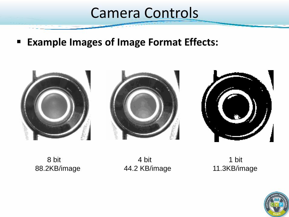
Example Images of Image Format Effects:
8 bit 4 bit 1 bit 88.2KB/image 44.2 KB/image 11.3KB/image
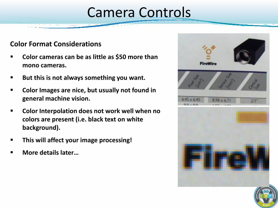
Color Format Considerations
Color cameras can be as little as $50 more than mono cameras.
But this is not always something you want.
Color Images are nice, but usually not found in general machine vision.
Color Interpolation does not work well when no colors are present (i.e. black text on white background).
This will affect your image processing!
More details later…
Camera Controls
Camera Controls Resolution (array size): The number of pixels in the sensor, i.e., 640x480
Resolution Considerations: More pixels can achieve higher detail. But more pixels is not necessarily better! More pixels = small pixels = low SNR. Small pixels are hard for lenses to resolve. Always choose the lowest resolution possible for the application. High resolution = high price too
Camera Controls
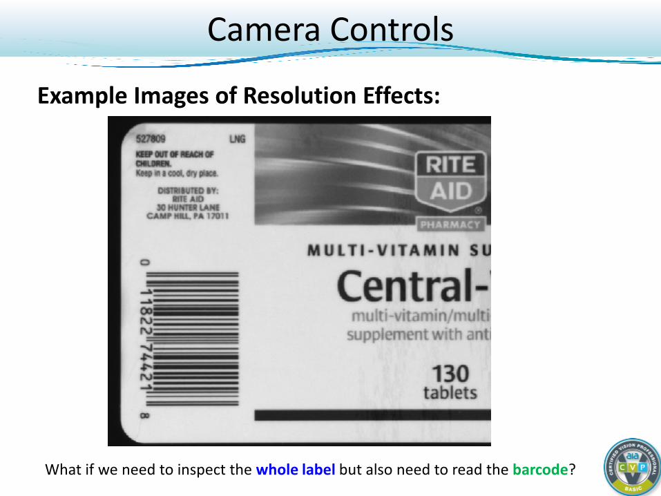
Example Images of Resolution Effects:
What if we need to inspect the whole label but also need to read the barcode?
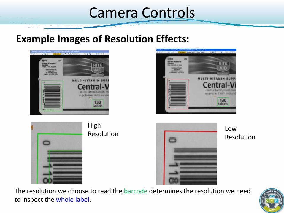
Camera Controls Example Images of Resolution Effects:
The resolution we choose to read the barcode determines the resolution we need to inspect the whole label.
High Resolution
Low Resolution
Summary / Tips Identify whether it is a low or high end application. Low end applications may only need frame rate, resolution, and a sample
image to select a camera. High end applications will need deeper data. Get the EMVA1288 reports,
manuals, sensor datasheets. Become familiar with the more common sensors:
ICX285, ICX445, IMX174, KAI1020, etc. Digital cameras are packed with features. Many that customers would
never think they need! Don’t let bad settings misrepresent image quality.

Digital Cameras: Basic Course
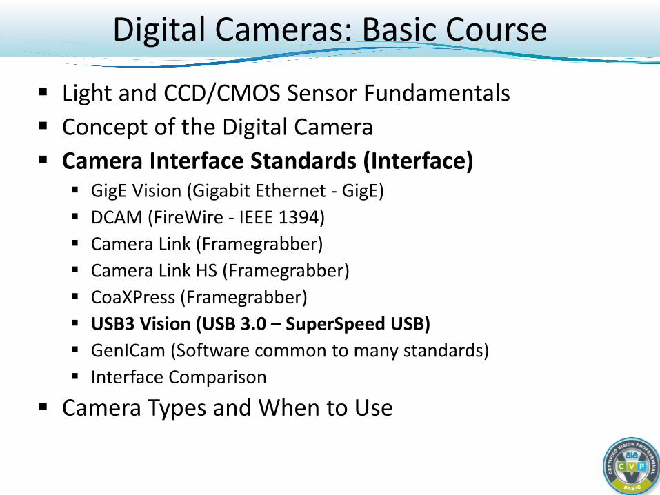
Light and CCD/CMOS Sensor Fundamentals Concept of the Digital Camera Camera Interface Standards (Interface) GigE Vision (Gigabit Ethernet - GigE) DCAM (FireWire - IEEE 1394) Camera Link (Framegrabber) Camera Link HS (Framegrabber) CoaXPress (Framegrabber) USB3 Vision (USB 3.0 – SuperSpeed USB) GenICam (Software common to many standards) Interface Comparison
Camera Types and When to Use
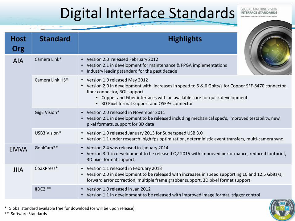
Digital Interface Standards Host Org
Standard Highlights
AIA Camera Link* • Version 2.0 released February 2012 • Version 2.1 in development for maintenance & FPGA implementations • Industry leading standard for the past decade
Camera Link HS* • Version 1.0 released May 2012 • Version 2.0 in development with increases in speed to 5 & 6 Gbits/s for Copper SFF-8470 connector,
fiber connector, ROI support • Copper and Fiber interfaces with an available core for quick development • 3D Pixel format support and QSFP+ connector
GigE Vision* • Version 2.0 released in November 2011 • Version 2.1 in development to be released including mechanical spec’s, improved testability, new
pixel formats, support for 3D data
USB3 Vision* • Version 1.0 released January 2013 for Superspeed USB 3.0 • Version 1.1 under research: high fps optimization, deterministic event transfers, multi-camera sync
EMVA GenICam** • Version 2.4 was released in January 2014 • Version 3.0 in development to be released Q2 2015 with improved performance, reduced footprint,
3D pixel format support
JIIA CoaXPress* • Version 1.1 released in February 2013 • Version 2.0 in development to be released with increases in speed supporting 10 and 12.5 Gbits/s,
forward error correction, multiple frame grabber support, 3D pixel format support
IIDC2 ** • Version 1.0 released in Jan 2012 • Version 1.1 In development to be released with improved image format, trigger control
* Global standard available free for download (or will be upon release) ** Software Standards
Digital Cameras: Basic Course
Light and CCD/CMOS Sensor Fundamentals Concept of the Digital Camera Camera Interface Standards (Interface)
GigE Vision (Gigabit Ethernet - GigE) DCAM (FireWire - IEEE 1394) Camera Link (Framegrabber) Camera Link HS (Framegrabber) CoaXPress (Framegrabber) USB3 Vision (USB 3.0 – SuperSpeed USB) GenICam (Software common to many standards) Interface Comparison
Camera Types and When to Use
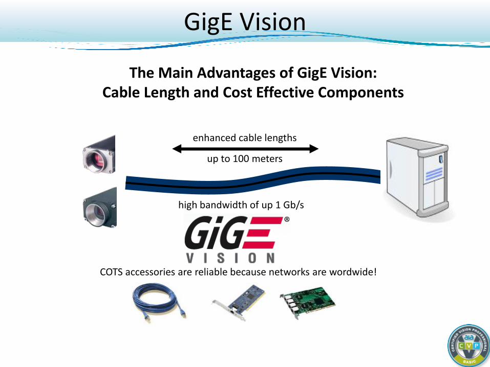
GigE Vision
enhanced cable lengths
up to 100 meters
high bandwidth of up 1 Gb/s
COTS accessories are reliable because networks are wordwide!
The Main Advantages of GigE Vision: Cable Length and Cost Effective Components
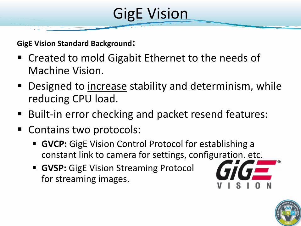
GigE Vision
GigE Vision Standard Background: Created to mold Gigabit Ethernet to the needs of
Machine Vision. Designed to increase stability and determinism, while
reducing CPU load. Built-in error checking and packet resend features: Contains two protocols: GVCP: GigE Vision Control Protocol for establishing a
constant link to camera for settings, configuration, etc. GVSP: GigE Vision Streaming Protocol
for streaming images.
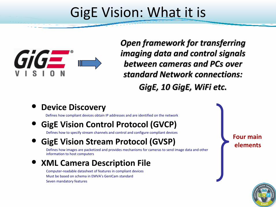
GigE Vision: What it is
• Device Discovery Defines how compliant devices obtain IP addresses and are identified on the network
• GigE Vision Control Protocol (GVCP) Defines how to specify stream channels and control and configure compliant devices
• GigE Vision Stream Protocol (GVSP) Defines how images are packetized and provides mechanisms for cameras to send image data and other information to host computers
• XML Camera Description File Computer-readable datasheet of features in compliant devices Must be based on schema in EMVA’s GenICam standard Seven mandatory features
Open framework for transferring imaging data and control signals between cameras and PCs over standard Network connections:
GigE, 10 GigE, WiFi etc.
Four main elements
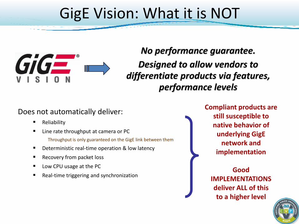
GigE Vision: What it is NOT
No performance guarantee. Designed to allow vendors to
differentiate products via features, performance levels
Does not automatically deliver: Reliability Line rate throughput at camera or PC
Throughput is only guaranteed on the GigE link between them
Deterministic real-time operation & low latency Recovery from packet loss Low CPU usage at the PC Real-time triggering and synchronization
Compliant products are still susceptible to native behavior of
underlying GigE network and
implementation
Good IMPLEMENTATIONS deliver ALL of this to a higher level
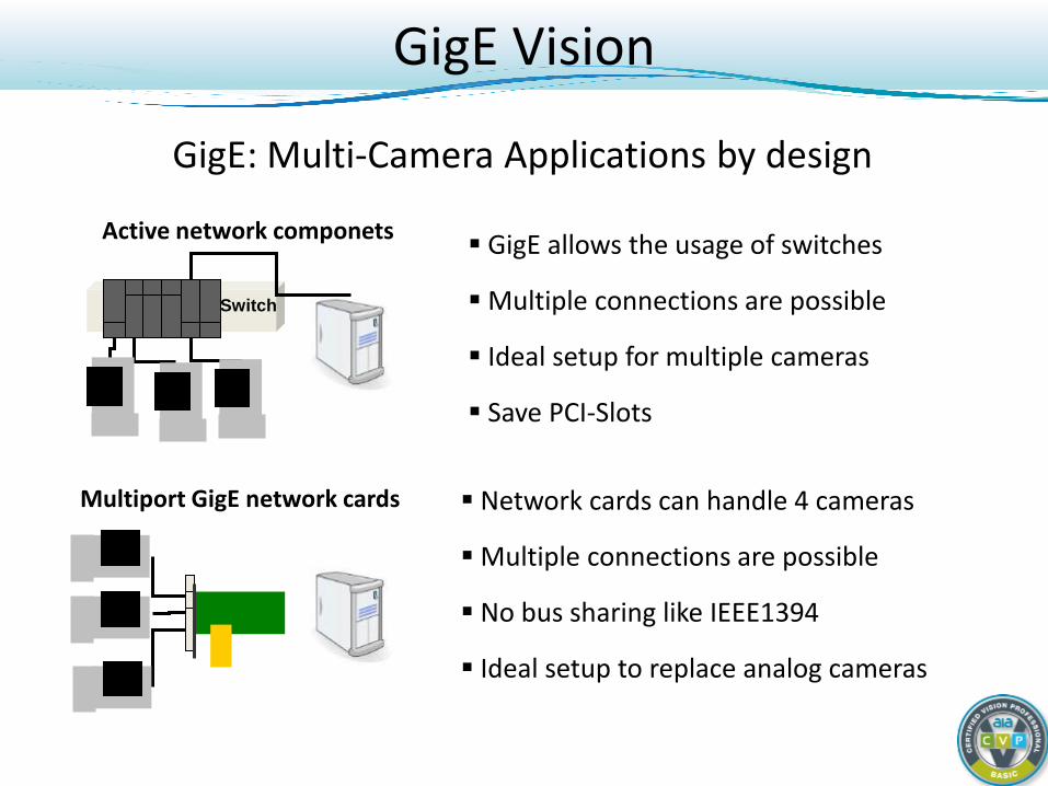
GigE Vision
Switch
Active network componets
Multiport GigE network cards
GigE allows the usage of switches
Multiple connections are possible
Ideal setup for multiple cameras
Save PCI-Slots
Network cards can handle 4 cameras
Multiple connections are possible
No bus sharing like IEEE1394
Ideal setup to replace analog cameras
GigE: Multi-Camera Applications by design
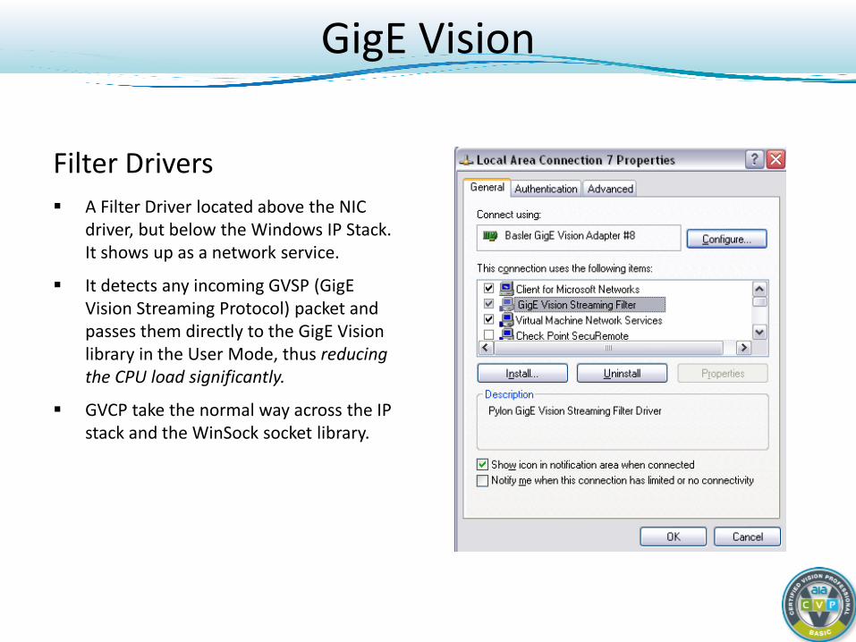
GigE Vision
Filter Drivers A Filter Driver located above the NIC
driver, but below the Windows IP Stack. It shows up as a network service.
It detects any incoming GVSP (GigE Vision Streaming Protocol) packet and passes them directly to the GigE Vision library in the User Mode, thus reducing the CPU load significantly.
GVCP take the normal way across the IP stack and the WinSock socket library.
GigE Vision
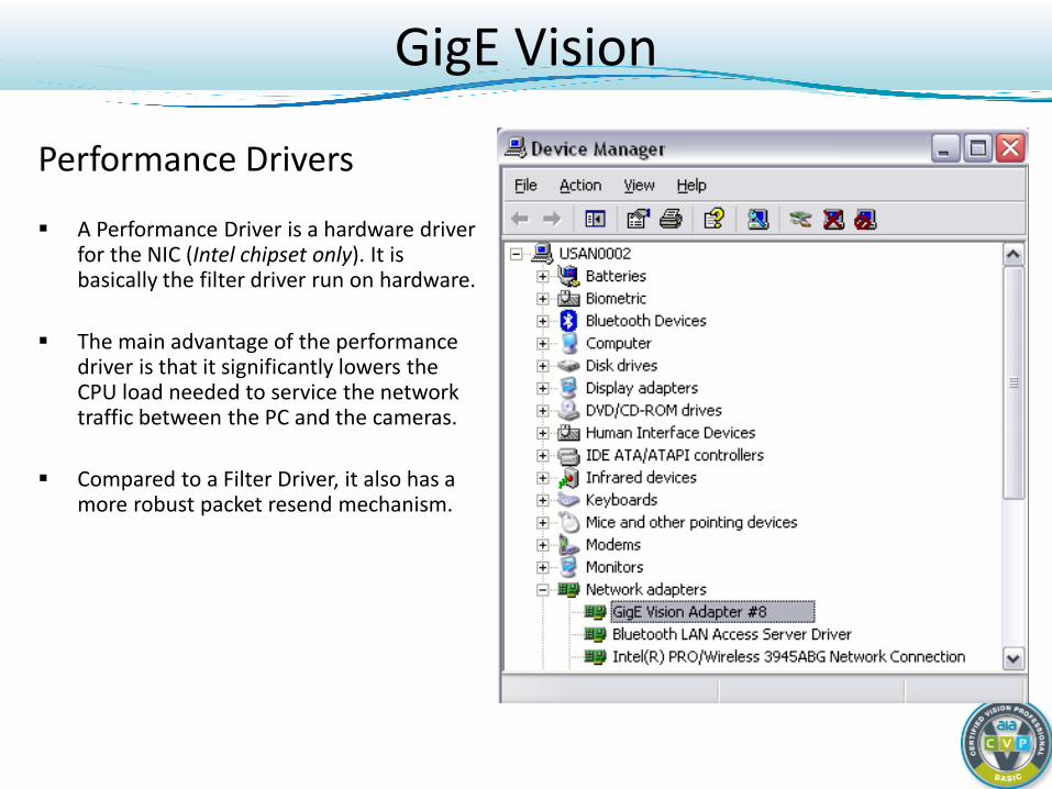
Performance Drivers
A Performance Driver is a hardware driver for the NIC (Intel chipset only). It is basically the filter driver run on hardware.
The main advantage of the performance driver is that it significantly lowers the CPU load needed to service the network traffic between the PC and the cameras.
Compared to a Filter Driver, it also has a more robust packet resend mechanism.
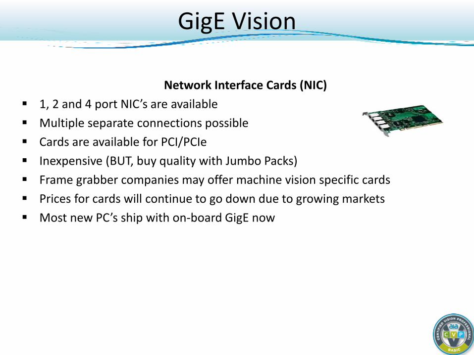
Network Interface Cards (NIC) 1, 2 and 4 port NIC’s are available Multiple separate connections possible Cards are available for PCI/PCIe Inexpensive (BUT, buy quality with Jumbo Packs) Frame grabber companies may offer machine vision specific cards Prices for cards will continue to go down due to growing markets Most new PC’s ship with on-board GigE now
GigE Vision
Ethernet Cable Categories
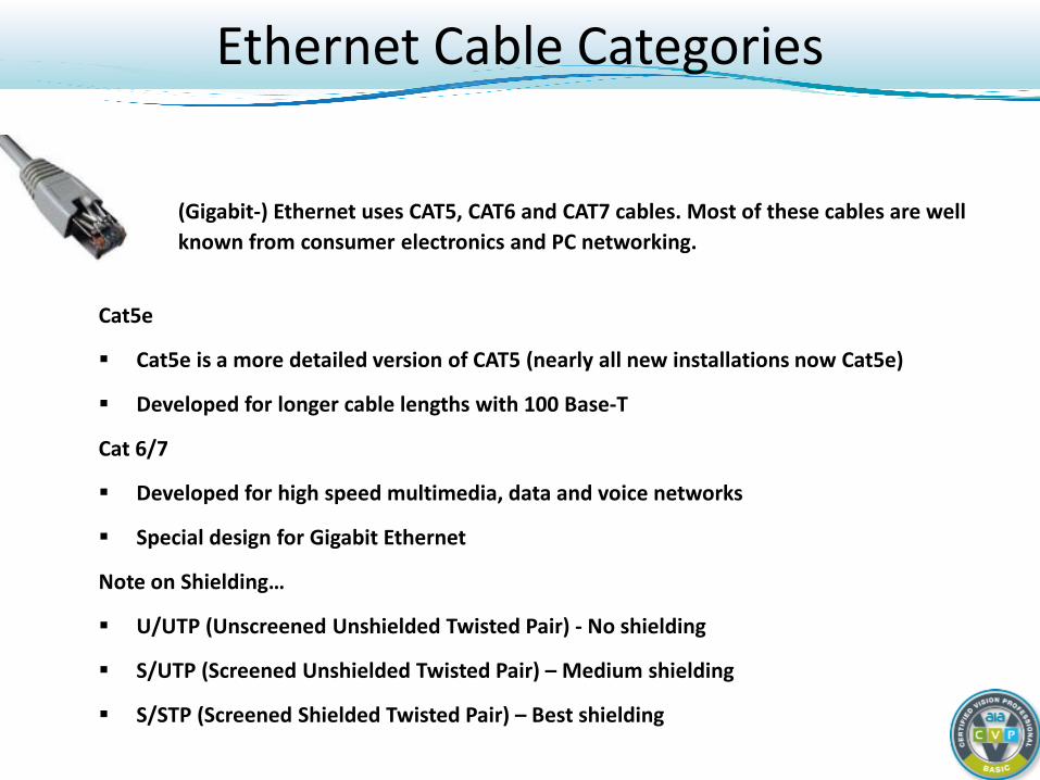
Cat5e
Cat5e is a more detailed version of CAT5 (nearly all new installations now Cat5e)
Developed for longer cable lengths with 100 Base-T
Cat 6/7
Developed for high speed multimedia, data and voice networks
Special design for Gigabit Ethernet
Note on Shielding…
U/UTP (Unscreened Unshielded Twisted Pair) - No shielding
S/UTP (Screened Unshielded Twisted Pair) – Medium shielding
S/STP (Screened Shielded Twisted Pair) – Best shielding
(Gigabit-) Ethernet uses CAT5, CAT6 and CAT7 cables. Most of these cables are well known from consumer electronics and PC networking.

Digital Cameras: Basic Course
Light and CCD/CMOS Sensor Fundamentals Concept of the Digital Camera Camera Interface Standards (Interface)
GigE Vision (Gigabit Ethernet - GigE) DCAM (FireWire - IEEE 1394) Camera Link (Framegrabber) Camera Link HS (Framegrabber) CoaXPress (Framegrabber) USB3 Vision (USB 3.0 – SuperSpeed USB) GenICam (Software common to many standards) Interface Comparison
Camera Types and When to Use
DCAM (IEEE 1394 - FireWire)
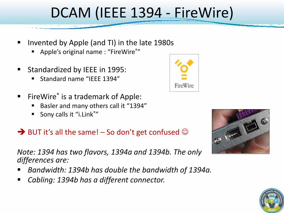
Invented by Apple (and TI) in the late 1980s Apple’s original name : “FireWire®”
Standardized by IEEE in 1995:
Standard name “IEEE 1394”
FireWire® is a trademark of Apple: Basler and many others call it “1394” Sony calls it “i.Link®”
BUT it’s all the same! – So don’t get confused
Note: 1394 has two flavors, 1394a and 1394b. The only differences are: Bandwidth: 1394b has double the bandwidth of 1394a. Cabling: 1394b has a different connector.
DCAM (IEEE 1394 - FireWire)
IIDC 1394-based Digital Camera Specification “DCAM”
Industry standard for 1394a/b digital cameras created in 1996 Specifies video formats, registers, features User can choose many combinations of camera and software vendors Most industrial 1394 camera makers are DCAM compliant Older interface, gradually dying out in the consumer market
DCAM (IEEE 1394 - FireWire)
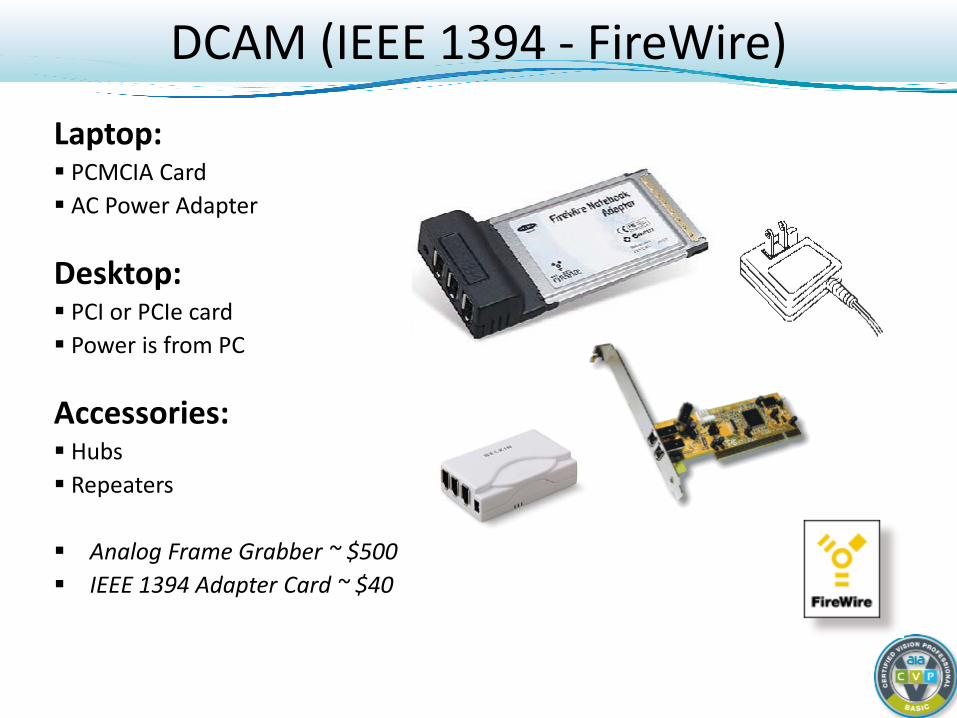
Laptop: PCMCIA Card AC Power Adapter
Desktop: PCI or PCIe card Power is from PC
Accessories: Hubs Repeaters Analog Frame Grabber ~ $500 IEEE 1394 Adapter Card ~ $40

Digital Cameras: Basic Course
Light and CCD/CMOS Sensor Fundamentals Concept of the Digital Camera Camera Interface Standards (Interface) GigE Vision (Gigabit Ethernet - GigE) DCAM (FireWire - IEEE 1394) Camera Link (Framegrabber) Camera Link HS (Framegrabber) CoaXPress (Framegrabber) USB3 Vision (USB 3.0 – SuperSpeed USB) GenICam (Software common to many standards) Interface Comparison
Camera Types and When to Use
Camera Link
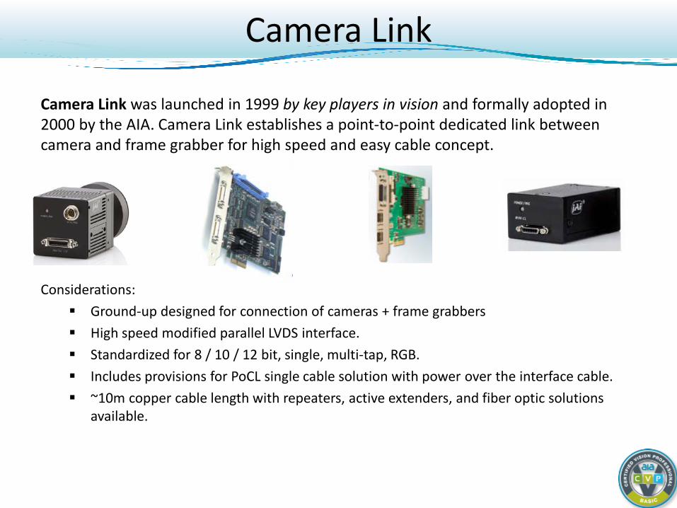
Camera Link was launched in 1999 by key players in vision and formally adopted in 2000 by the AIA. Camera Link establishes a point-to-point dedicated link between camera and frame grabber for high speed and easy cable concept.
Considerations: Ground-up designed for connection of cameras + frame grabbers High speed modified parallel LVDS interface. Standardized for 8 / 10 / 12 bit, single, multi-tap, RGB. Includes provisions for PoCL single cable solution with power over the interface cable. ~10m copper cable length with repeaters, active extenders, and fiber optic solutions
available.
TxIN
LVAL
DVALFVAL
Spare
Port G
Port H
TxIN
LVAL
DVALFVAL
Spare
Port D
Port E
TxIN
LVAL
DVALFVAL
Spare
Port A
Port B
Port F
Port C
Transmitter 3
Transmitter 2
Transmitter 1
CameraControlSignals
Camera MDRCable
MDRCable
RxOut
LVAL
DVALFVAL
Spare
Port G
Port H
RxOut
LVAL
DVALFVAL
Spare
Port D
Port E
RxOut
LVAL
DVALFVAL
Spare
Port A
Port B
Port F
Port C
Receiver 3
Receiver 2
Receiver 1
Frame Grabber
Clk
Clk
Clk
Clk
Clk
Clk
CameraControlSignals
SerialCommu-nication
SerialCommu-nication
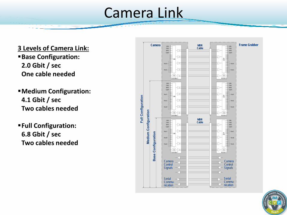
3 Levels of Camera Link: Base Configuration:
2.0 Gbit / sec One cable needed Medium Configuration:
4.1 Gbit / sec Two cables needed Full Configuration:
6.8 Gbit / sec Two cables needed
Camera Link
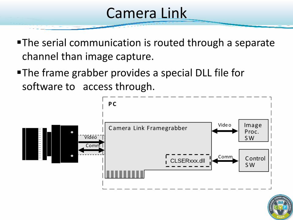
Camera Link
The serial communication is routed through a separate channel than image capture. The frame grabber provides a special DLL file for
software to access through.
I m a g e P r o c . S W
C o n t r o l S W
P C
C a m e r a L i n k F r a m e g r a b b e r V i d e o
C o m m .
V i d e o
C o m m . CLSERxxx.dll
Camera Link
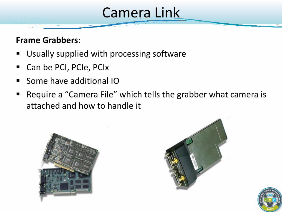
Frame Grabbers: Usually supplied with processing software Can be PCI, PCIe, PCIx Some have additional IO Require a “Camera File” which tells the grabber what camera is
attached and how to handle it
Camera Link
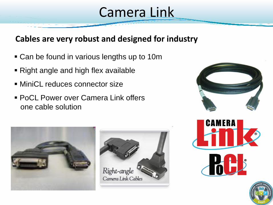
Cables are very robust and designed for industry
Can be found in various lengths up to 10m
Right angle and high flex available
MiniCL reduces connector size
PoCL Power over Camera Link offers one cable solution

Digital Cameras: Basic Course
Light and CCD/CMOS Sensor Fundamentals Concept of the Digital Camera Camera Interface Standards (Interface) GigE Vision (Gigabit Ethernet - GigE) DCAM (FireWire - IEEE 1394) Camera Link (Framegrabber) Camera Link HS (Framegrabber) CoaXPress (Framegrabber) USB3 Vision (USB 3.0 – SuperSpeed USB) GenICam (Software common to many standards) Interface Comparison
Camera Types and When to Use
Camera Link HS
Camera Link HS (CLHS) is a good choice for:
Demanding machine vision applications… with high bandwidth, (16.8Gbits/s) real-time demands, and error free data transmission needs.
Camera Link HS Design Goals
• Successor of Camera Link • CLHS keeps Camera Link advantages:
– High speed – Reliability – Real-time guarantee – Both Copper and Fiber options defined
• CLHS is far superior by: – Increased bandwidth – Much longer cables (10K meters) – Plug & Play capability
Camera Link HS Reliability
• High degree of transfer reliability
• Headers and real time signals ensured by 2 of 3 voting
• CRC-32 check and resend for video and communications
• Fiber optic offers immunity to electric and magnetic fields
Digital Cameras: Basic Course
Light and CCD/CMOS Sensor Fundamentals Concept of the Digital Camera Camera Interface Standards (Interface) GigE Vision (Gigabit Ethernet - GigE) DCAM (FireWire - IEEE 1394) Camera Link (Framegrabber) Camera Link HS (Framegrabber) CoaXPress (Framegrabber) USB3 Vision (USB 3.0 – SuperSpeed USB) GenICam (Software common to many standards) Interface Comparison
Camera Types and When to Use
CoaXPress - A Brief History
Pan-European R&D Project: 2007 - Adimec and EqcoLogic research high speed interface options 2008 - Technology demonstrator at Vision 2008, Stuttgart, Germany CoaXPress Consortium formed early 2009: Adimec (NL) ………………………… Cameras Active Silicon (UK) …………………. Frame Grabbers EqcoLogic (BE) ……………………. Transceivers Components Express (USA) ……… Cable Solutions AVAL DATA (JP) …………………… Frame Grabbers NED (JP) ……………………………. Line-scan Cameras 2010 – Version 1.0 released 2013 – Version 1.1 released Further updates in development
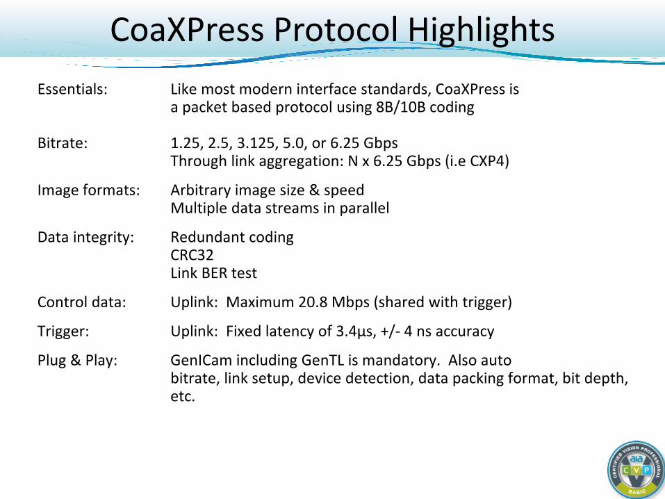
CoaXPress Protocol Highlights Essentials: Like most modern interface standards, CoaXPress is
a packet based protocol using 8B/10B coding Bitrate: 1.25, 2.5, 3.125, 5.0, or 6.25 Gbps
Through link aggregation: N x 6.25 Gbps (i.e CXP4)
Image formats: Arbitrary image size & speed Multiple data streams in parallel
Data integrity: Redundant coding CRC32 Link BER test
Control data: Uplink: Maximum 20.8 Mbps (shared with trigger)
Trigger: Uplink: Fixed latency of 3.4µs, +/- 4 ns accuracy
Plug & Play: GenICam including GenTL is mandatory. Also auto bitrate, link setup, device detection, data packing format, bit depth, etc.
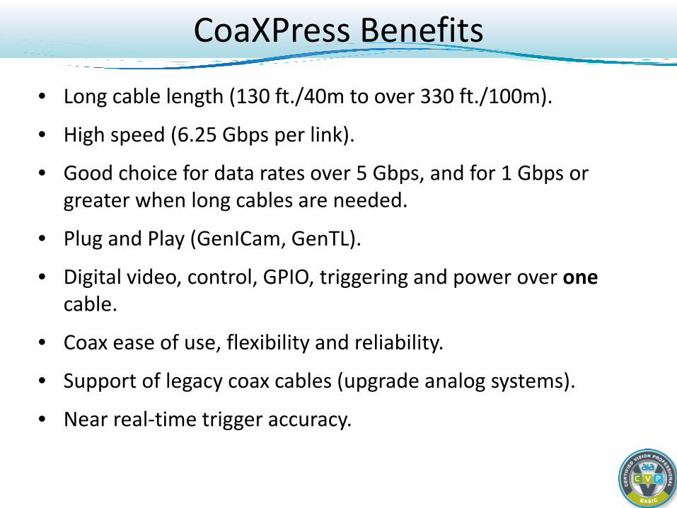
CoaXPress Benefits
• Long cable length (130 ft./40m to over 330 ft./100m).
• High speed (6.25 Gbps per link).
• Good choice for data rates over 5 Gbps, and for 1 Gbps or greater when long cables are needed.
• Plug and Play (GenICam, GenTL).
• Digital video, control, GPIO, triggering and power over one cable.
• Coax ease of use, flexibility and reliability.
• Support of legacy coax cables (upgrade analog systems).
• Near real-time trigger accuracy.
Digital Cameras: Basic Course
Light and CCD/CMOS Sensor Fundamentals Concept of the Digital Camera Camera Interface Standards (Interface) GigE Vision (Gigabit Ethernet - GigE) DCAM (FireWire - IEEE 1394) Camera Link (Framegrabber) Camera Link HS (Framegrabber) CoaXPress (Framegrabber) USB3 Vision (USB 3.0 – SuperSpeed USB) GenICam (Software common to many standards) Interface Comparison
Camera Types and When to Use
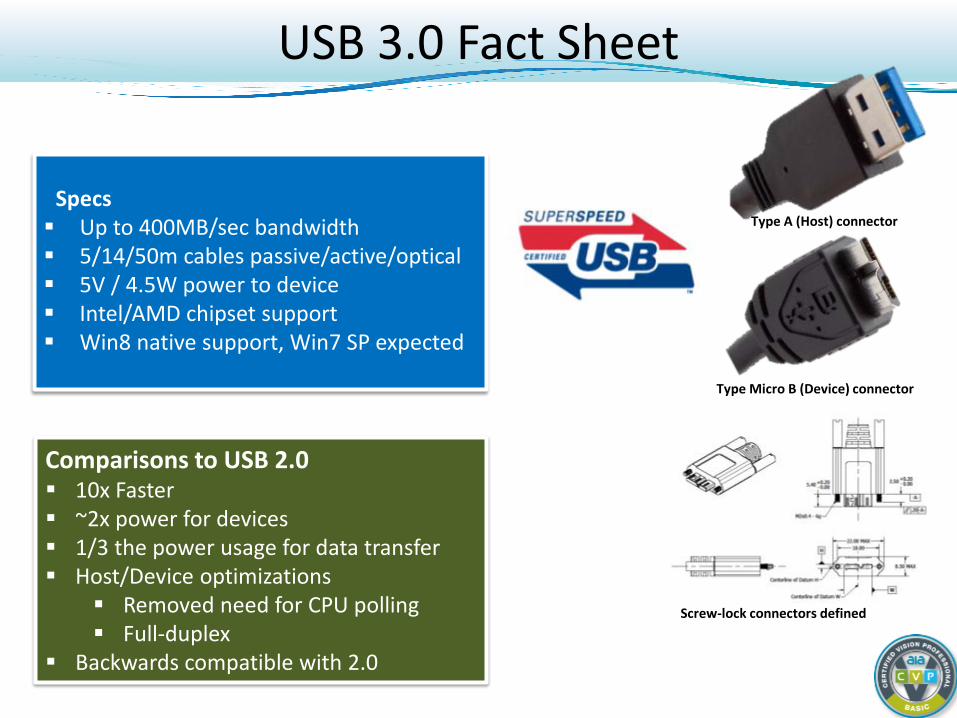
USB 3.0 Fact Sheet
Specs Up to 400MB/sec bandwidth 5/14/50m cables passive/active/optical 5V / 4.5W power to device Intel/AMD chipset support Win8 native support, Win7 SP expected
Type A (Host) connector
Type Micro B (Device) connector
Screw-lock connectors defined
Comparisons to USB 2.0 10x Faster ~2x power for devices 1/3 the power usage for data transfer Host/Device optimizations
Removed need for CPU polling Full-duplex
Backwards compatible with 2.0
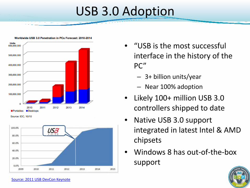
USB 3.0 Adoption
• “USB is the most successful interface in the history of the PC” – 3+ billion units/year – Near 100% adoption
• Likely 100+ million USB 3.0 controllers shipped to date
• Native USB 3.0 support integrated in latest Intel & AMD chipsets
• Windows 8 has out-of-the-box support
Source: 2011 USB DevCon Keynote
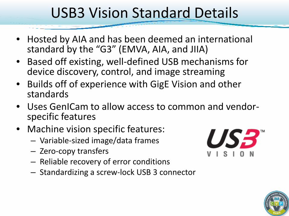
USB3 Vision Standard Details • Hosted by AIA and has been deemed an international
standard by the “G3” (EMVA, AIA, and JIIA) • Based off existing, well-defined USB mechanisms for
device discovery, control, and image streaming • Builds off of experience with GigE Vision and other
standards • Uses GenICam to allow access to common and vendor-
specific features • Machine vision specific features:
– Variable-sized image/data frames – Zero-copy transfers – Reliable recovery of error conditions – Standardizing a screw-lock USB 3 connector
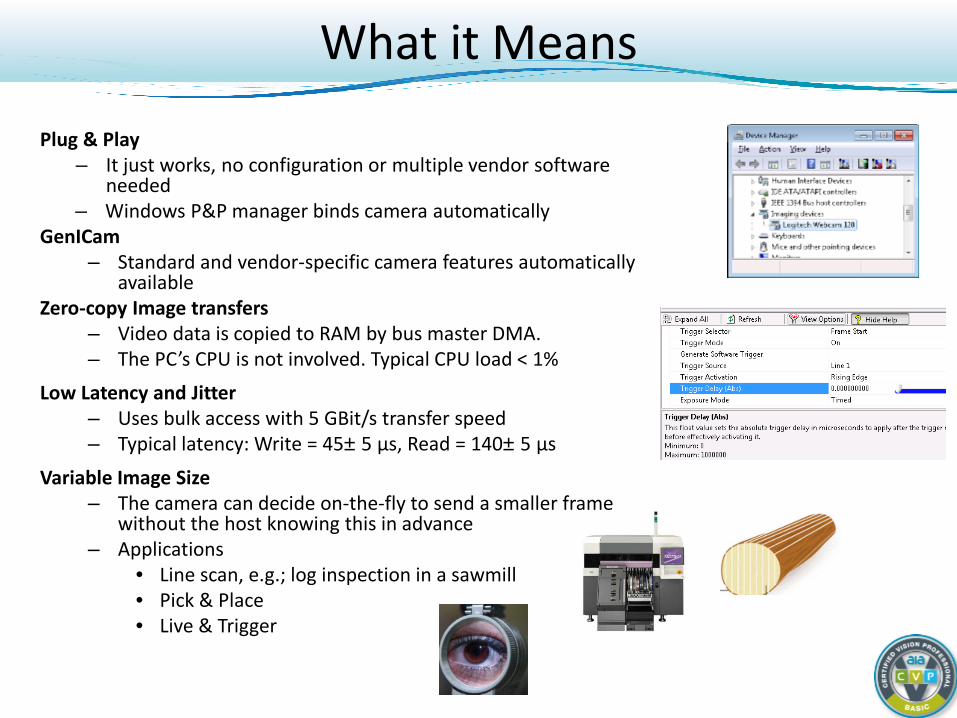
What it Means
Plug & Play – It just works, no configuration or multiple vendor software
needed – Windows P&P manager binds camera automatically
GenICam – Standard and vendor-specific camera features automatically
available Zero-copy Image transfers
– Video data is copied to RAM by bus master DMA. – The PC’s CPU is not involved. Typical CPU load < 1%
Low Latency and Jitter – Uses bulk access with 5 GBit/s transfer speed – Typical latency: Write = 45±5 µs, Read = 140±5 µs
Variable Image Size – The camera can decide on-the-fly to send a smaller frame
without the host knowing this in advance – Applications
• Line scan, e.g.; log inspection in a sawmill • Pick & Place • Live & Trigger

Digital Cameras: Basic Course
Light and CCD/CMOS Sensor Fundamentals Concept of the Digital Camera Camera Interface Standards (Interface) GigE Vision (Gigabit Ethernet - GigE) DCAM (FireWire - IEEE 1394) Camera Link (Framegrabber) Camera Link HS (Framegrabber) CoaXPress (Framegrabber) USB3 Vision (USB 3.0 – SuperSpeed USB) GenICam (Software common to many standards) Interface Comparison
Camera Types and When to Use
GenICam Standard
• The Goal of GeniCam is to unite the various machine vision interfaces
• Cooperatively developed by industry-leading vendors • Hosted by European Machine Vision Association (EMVA)
– www.genicam.org
• Unified API to seamlessly control many interfaces with one program
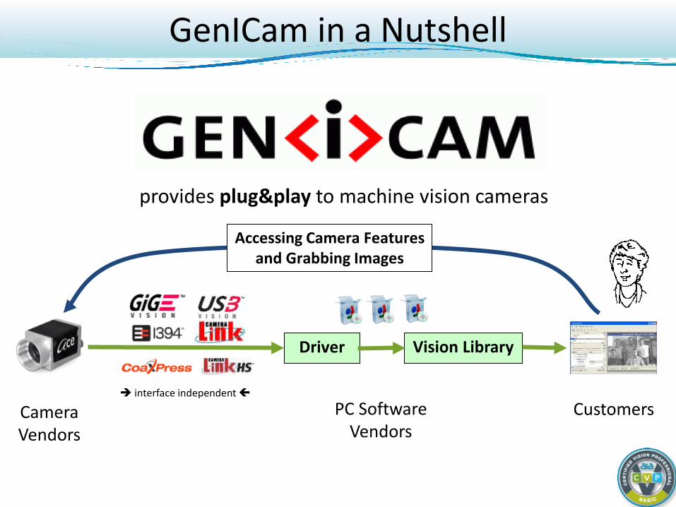
provides plug&play to machine vision cameras
Customers
Driver Vision Library
Camera Vendors
PC Software Vendors
Accessing Camera Features and Grabbing Images
interface independent
GenICam in a Nutshell
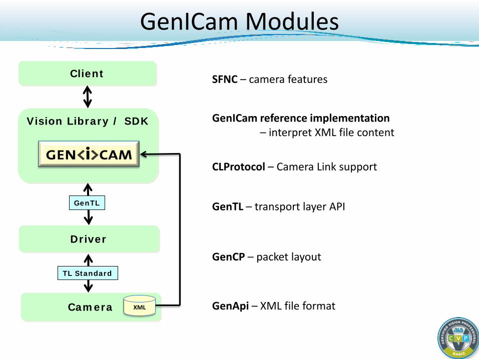
Vision Library / SDK
GenICam Modules
Client
Driver
TL Standard
Camera XML GenApi – XML file format
SFNC – camera features
GenCP – packet layout
GenICam reference implementation – interpret XML file content
GenTL GenTL – transport layer API
CLProtocol – Camera Link support
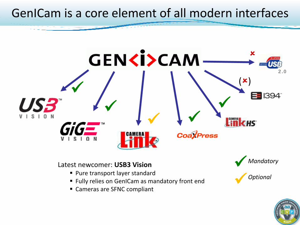
GenICam is a core element of all modern interfaces
Latest newcomer: USB3 Vision Pure transport layer standard Fully relies on GenICam as mandatory front end Cameras are SFNC compliant
2.0
()
Mandatory Optional
Digital Cameras: Basic Course
Light and CCD/CMOS Sensor Fundamentals Concept of the Digital Camera Camera Interface Standards (Interface) GigE Vision (Gigabit Ethernet - GigE) DCAM (FireWire - IEEE 1394) Camera Link (Framegrabber) Camera Link HS (Framegrabber) CoaXPress (Framegrabber) USB3 Vision (USB 3.0 – SuperSpeed USB) GenICam (Software common to many standards) Interface Comparison
Camera Types and When to Use
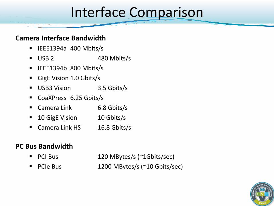
Interface Comparison Camera Interface Bandwidth
IEEE1394a 400 Mbits/s USB 2 480 Mbits/s IEEE1394b 800 Mbits/s GigE Vision 1.0 Gbits/s USB3 Vision 3.5 Gbits/s CoaXPress 6.25 Gbits/s Camera Link 6.8 Gbits/s 10 GigE Vision 10 Gbits/s Camera Link HS 16.8 Gbits/s
PC Bus Bandwidth
PCI Bus 120 MBytes/s (~1Gbits/sec) PCIe Bus 1200 MBytes/s (~10 Gbits/sec)
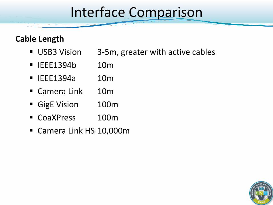
Interface Comparison
Cable Length USB3 Vision 3-5m, greater with active cables IEEE1394b 10m IEEE1394a 10m Camera Link 10m GigE Vision 100m CoaXPress 100m Camera Link HS 10,000m
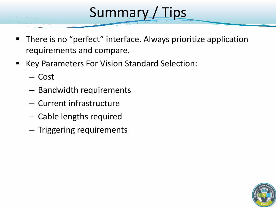
Summary / Tips
There is no “perfect” interface. Always prioritize application requirements and compare.
Key Parameters For Vision Standard Selection: – Cost – Bandwidth requirements – Current infrastructure – Cable lengths required – Triggering requirements

Digital Cameras: Basic Course
Light and CCD/CMOS Sensor Fundamentals Concept of the Digital Camera Camera Interface Standards Camera Types and When to Use Area scan Line scan
Area Scan
Main aspects Architecture AOI Binning Color
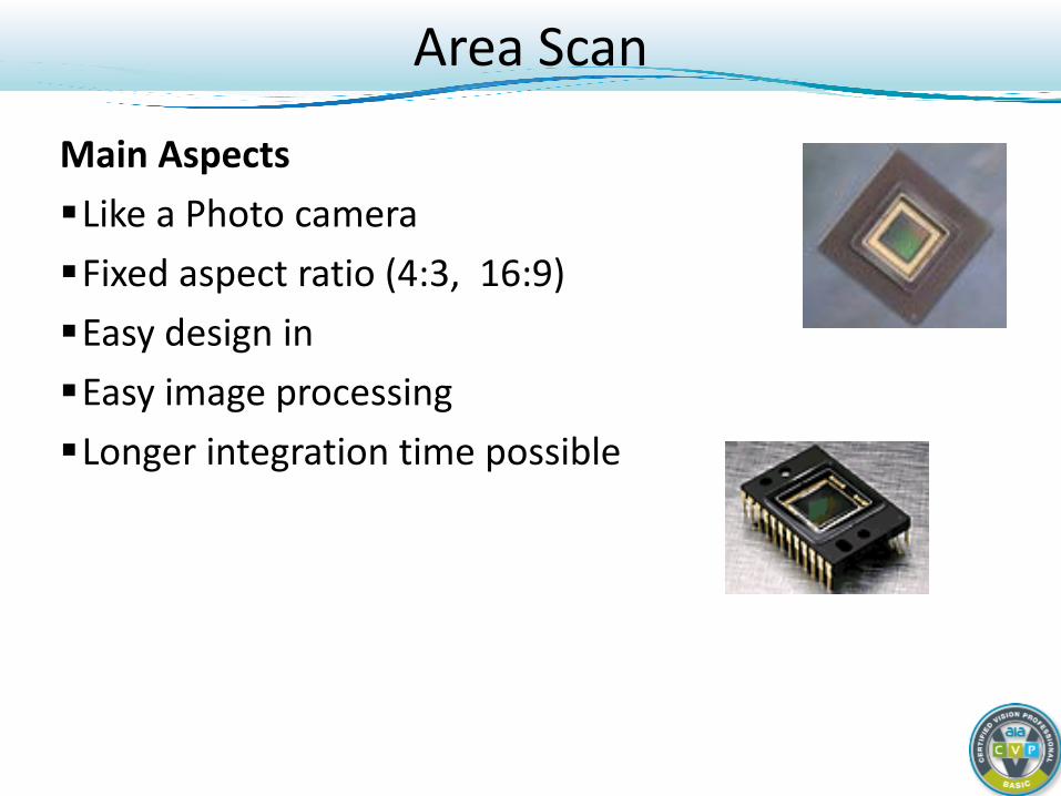
Area Scan
Main Aspects Like a Photo camera Fixed aspect ratio (4:3, 16:9) Easy design in Easy image processing Longer integration time possible
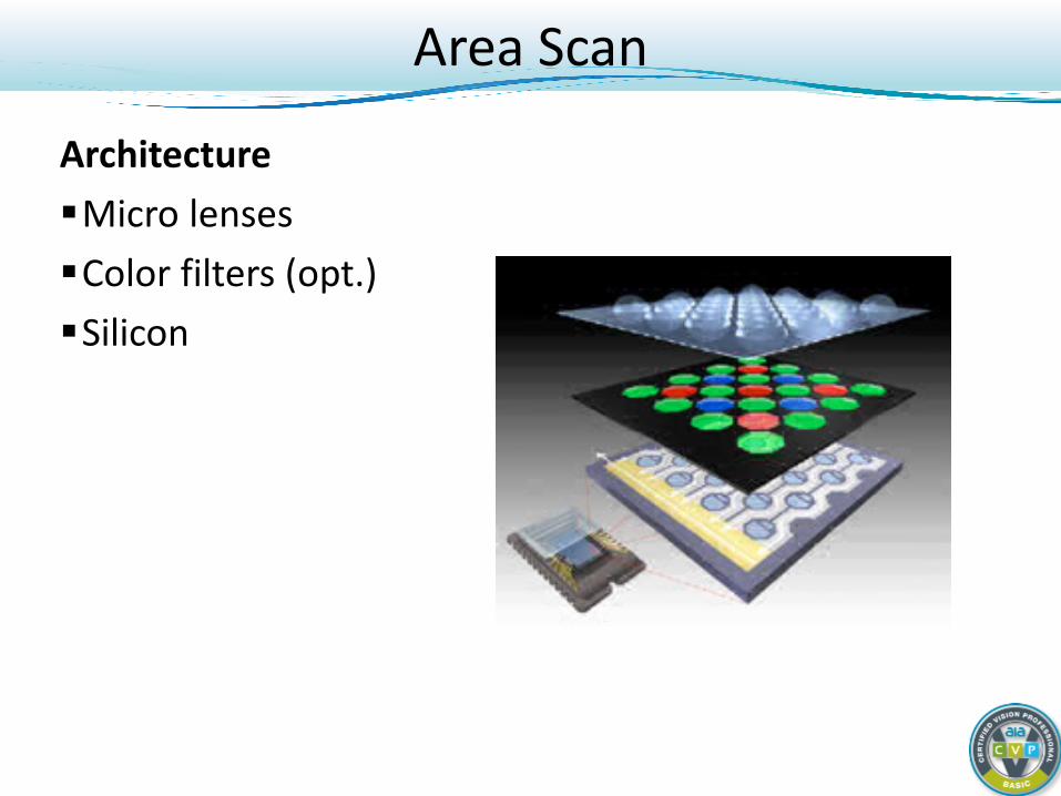
Area Scan
Architecture Micro lenses Color filters (opt.) Silicon
Area Scan
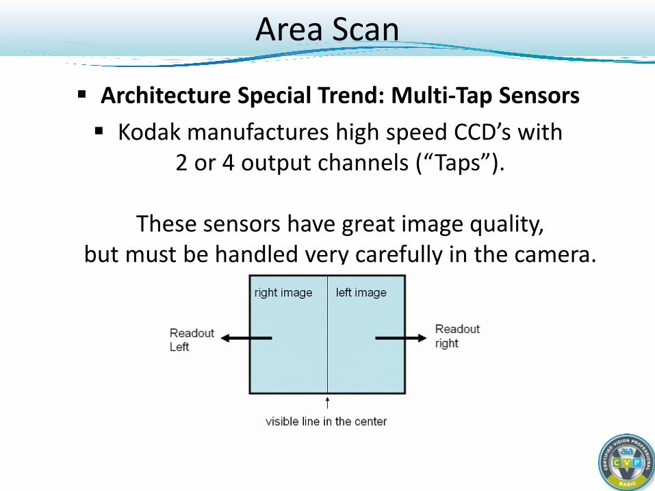
Architecture Special Trend: Multi-Tap Sensors Kodak manufactures high speed CCD’s with
2 or 4 output channels (“Taps”).
These sensors have great image quality, but must be handled very carefully in the camera.
Area Scan
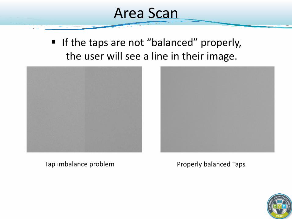
If the taps are not “balanced” properly, the user will see a line in their image.
Tap imbalance problem Properly balanced Taps
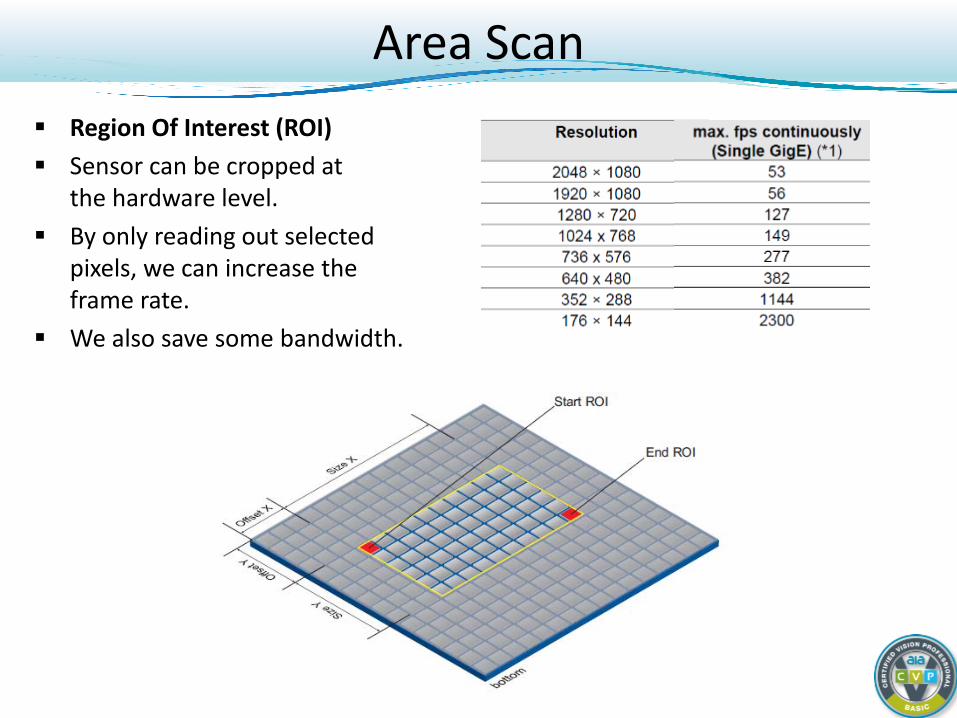
Area Scan Region Of Interest (ROI) Sensor can be cropped at
the hardware level. By only reading out selected
pixels, we can increase the frame rate.
We also save some bandwidth.
Area Scan
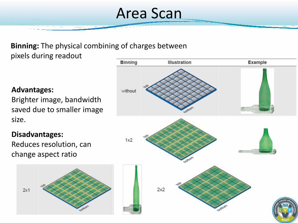
Binning: The physical combining of charges between pixels during readout
Advantages: Brighter image, bandwidth saved due to smaller image size.
Disadvantages: Reduces resolution, can change aspect ratio
Area Scan
COLOR
3- CCD 1- CCD (Bayer)
Area Scan
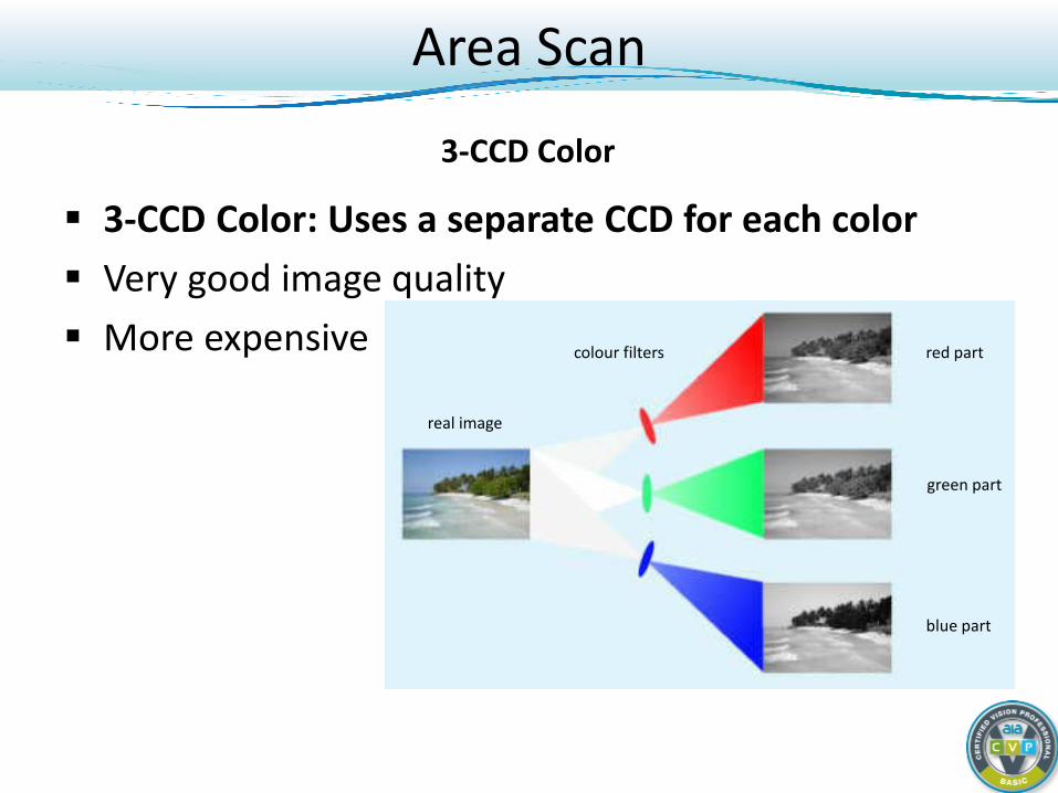
3-CCD Color: Uses a separate CCD for each color Very good image quality More expensive colour filters red part
green part
blue part
real image
3-CCD Color
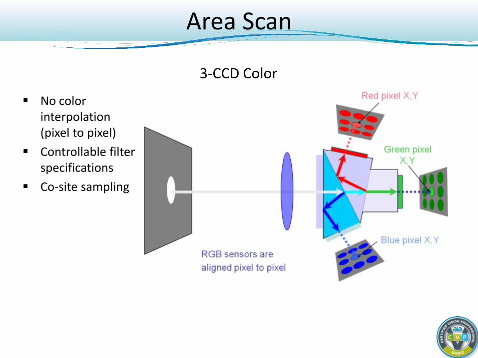
3-CCD Color
No color interpolation (pixel to pixel)
Controllable filter specifications
Co-site sampling
Area Scan
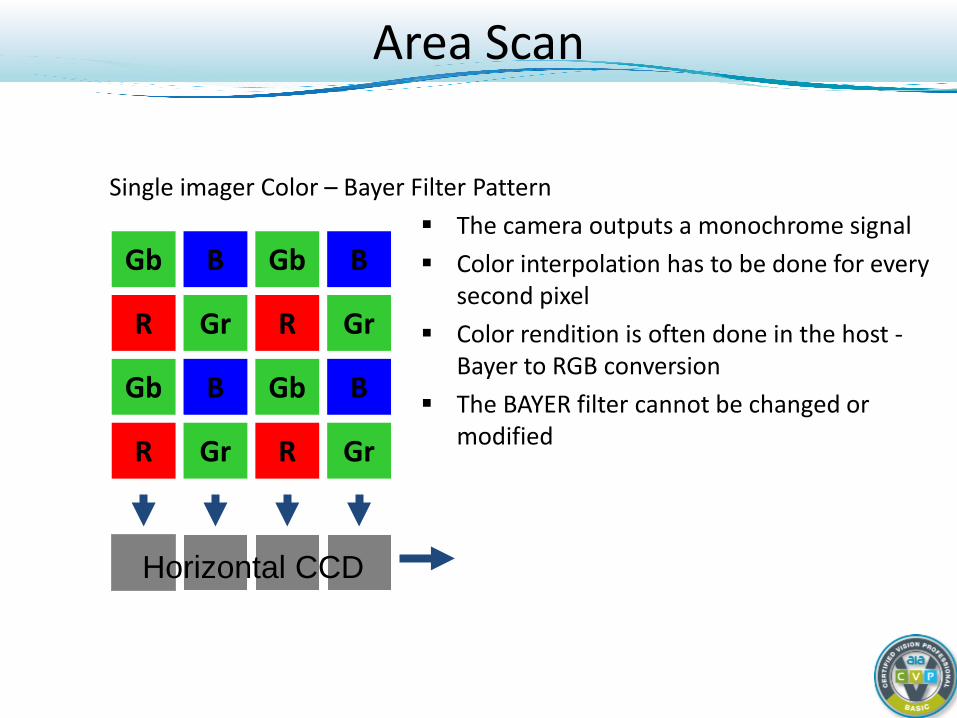
Single imager Color – Bayer Filter Pattern The camera outputs a monochrome signal Color interpolation has to be done for every
second pixel Color rendition is often done in the host -
Bayer to RGB conversion The BAYER filter cannot be changed or
modified
Gb Gb B B
R R Gr Gr
Horizontal CCD
Gb Gb B B
R R Gr Gr
Area Scan
Area Scan
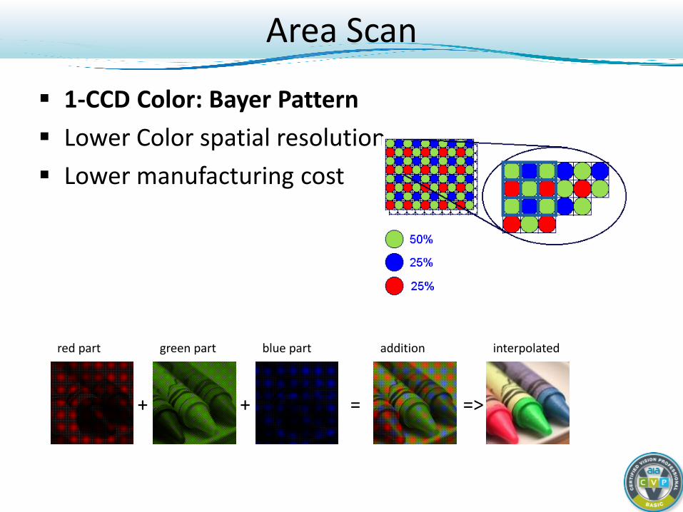
1-CCD Color: Bayer Pattern Lower Color spatial resolution Lower manufacturing cost
red part green part blue part addition interpolated
= => + +
Area Scan
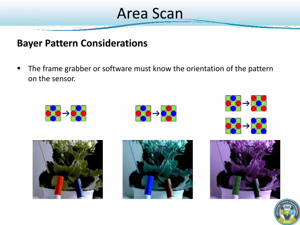
Bayer Pattern Considerations The frame grabber or software must know the orientation of the pattern
on the sensor.
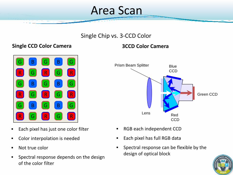
Single CCD Color Camera
Each pixel has just one color filter
Color interpolation is needed
Not true color
Spectral response depends on the design of the color filter
3CCD Color Camera
R
R
R
G
B
G
B
B
G
G
G
G R
R
R
G
G
G
B
G
B
B
G
G R
R
R
G
G
G
Prism Beam Splitter
Lens
Blue CCD
Green CCD
Red CCD
RGB each independent CCD
Each pixel has full RGB data
Spectral response can be flexible by the design of optical block
Single Chip vs. 3-CCD Color
Area Scan
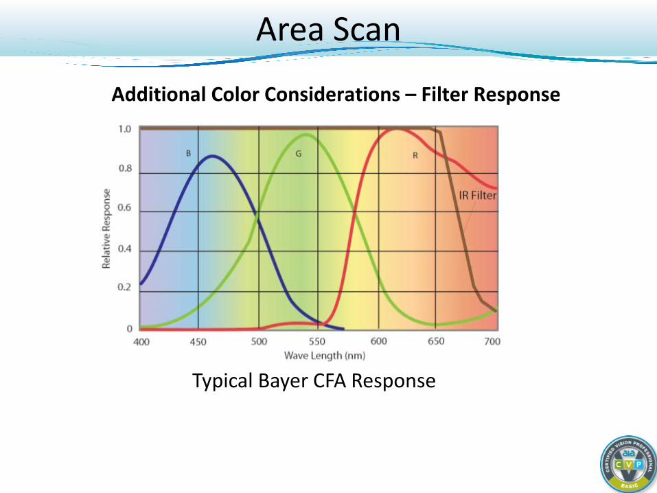
Area Scan
Typical Bayer CFA Response
Additional Color Considerations – Filter Response
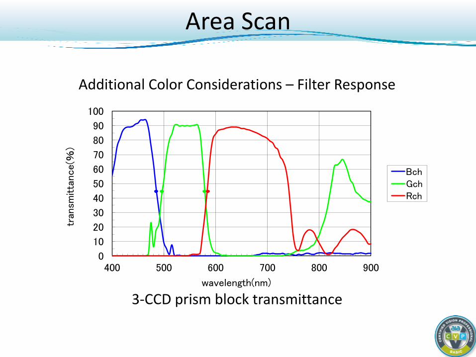
Additional Color Considerations – Filter Response
3-CCD prism block transmittance
0
10
20
30
40
50
60
70
80
90
100
400 500 600 700 800 900
tran
smitta
nce(%
)
wavelength(nm)
BchGchRch
Area Scan
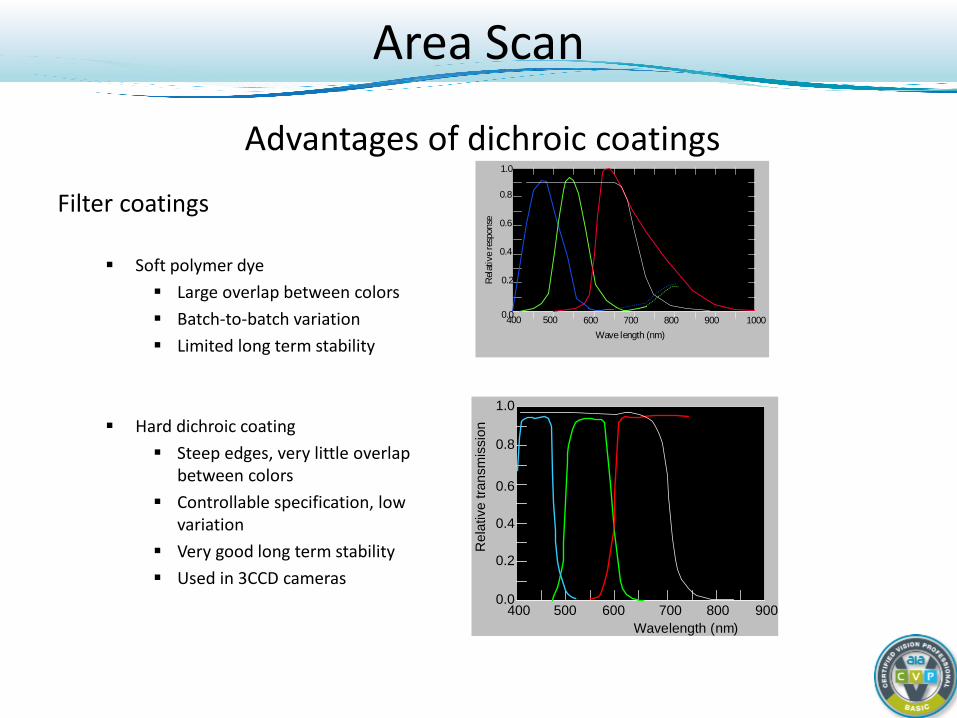
Filter coatings
Soft polymer dye Large overlap between colors Batch-to-batch variation Limited long term stability
Hard dichroic coating Steep edges, very little overlap
between colors Controllable specification, low
variation Very good long term stability Used in 3CCD cameras
400 500 600 700 800 900 1000Wave length (nm)
1.0
0.8
0.6
0.4
0.2
0.0
Rel
ativ
e re
spon
se
B G R
IR stopfilter
Wave length (nm)400 500 600 700 800 900
1.0
0.8
0.6
0.4
0.2
0.0
Rel
ativ
e tra
nsm
issi
onIR stop
B G R
Advantages of dichroic coatings
Area Scan
Digital Cameras: Basic Course
Light and CCD/CMOS Sensor Fundamentals Concept of the Digital Camera Camera Interface Standards Camera Types and When to Use Area scan Line scan
Line Scan
Main aspects How does that work? Architecture Trigger Color
Line Scan
Main Aspects Like a scanner or fax 2nd dimensions comes by movement Very good price / pixel performance High pixel fill-factor - typically 100%
Typically big pixels
Smear-free images Very short integration times Illumination intensity generally needs to be high Difficult design in / image processing
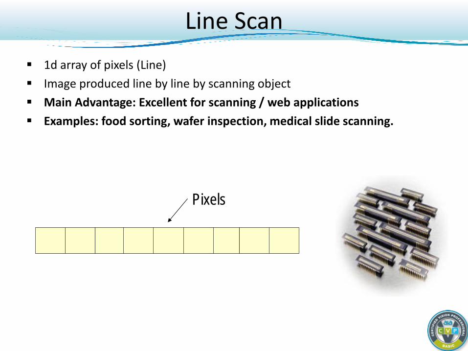
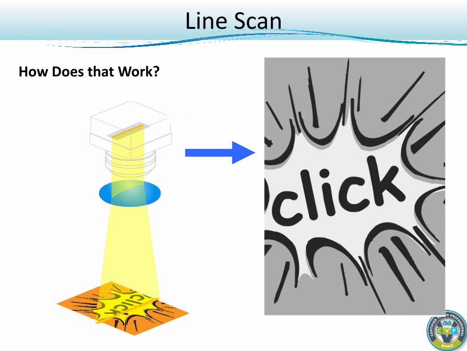
Line Scan 1d array of pixels (Line) Image produced line by line by scanning object Main Advantage: Excellent for scanning / web applications Examples: food sorting, wafer inspection, medical slide scanning.
Pixels
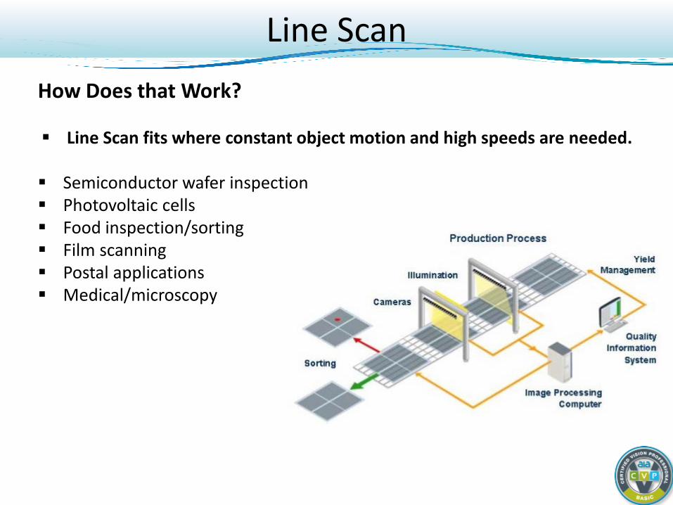
Line Scan How Does that Work? Line Scan fits where constant object motion and high speeds are needed.
Semiconductor wafer inspection Photovoltaic cells Food inspection/sorting Film scanning Postal applications Medical/microscopy
Line Scan
How Does that Work?
Line Scan
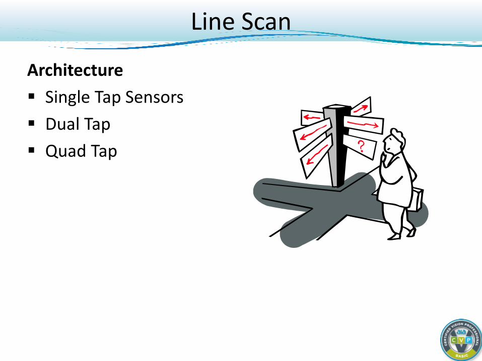
Architecture Single Tap Sensors Dual Tap Quad Tap
Line Scan
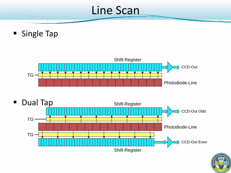
Single Tap Dual Tap
CCD-Out
TG
Photodiode-Line
Shift-Register
CCD-Out Odd
CCD-Out Even
TG
TG
Photodiode-Line
Shift-Register
Shift-Register
Line Scan
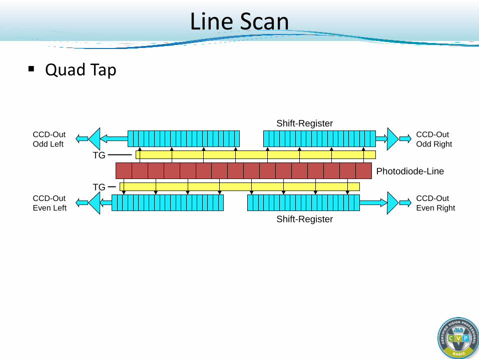
Quad Tap
CCD-Out Odd Right
CCD-Out Even Right
TG
TG
Photodiode-Line
Shift-Register
Shift-Register
CCD-Out Odd Left
CCD-Out Even Left
Line Scan
Color Types of color Line Scan Tri-linear in more detail Summary
Line Scan
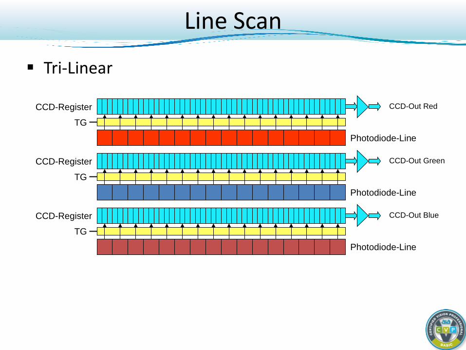
Tri-Linear
CCD-Out Red
TG
CCD-Out Green
TG
CCD-Out Blue
TG
Photodiode-Line
CCD-Register
Photodiode-Line
Photodiode-Line
CCD-Register
CCD-Register
Line Scan
A tri-linear line scan camera takes three different scans, but the red, green, and blue line do not look onto the same position of the object.
Falling and rotating objects can only be inspected by the colors individually.
Visualization is difficult, but machine vision is possible.
Line Scan
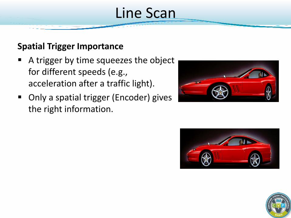
Spatial Trigger Importance A trigger by time squeezes the object
for different speeds (e.g., acceleration after a traffic light).
Only a spatial trigger (Encoder) gives the right information.
Line Scan
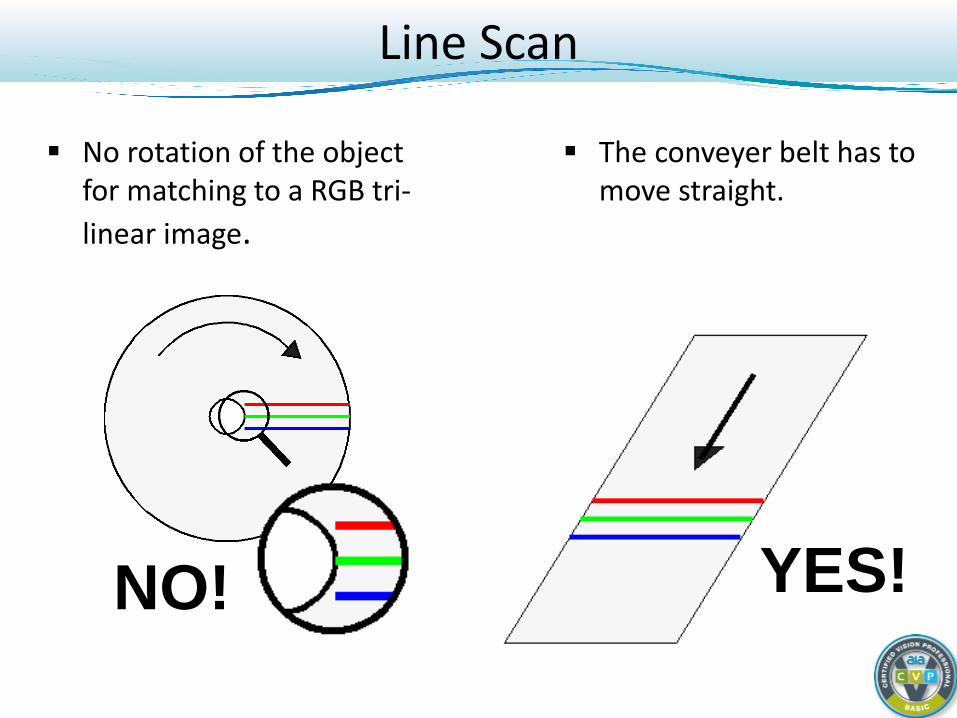
The conveyer belt has to move straight.
No rotation of the object for matching to a RGB tri-linear image.
NO! YES!
Line Scan
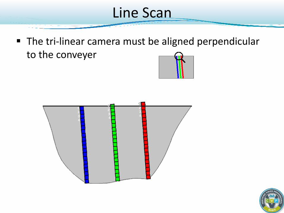
The tri-linear camera must be aligned perpendicular to the conveyer
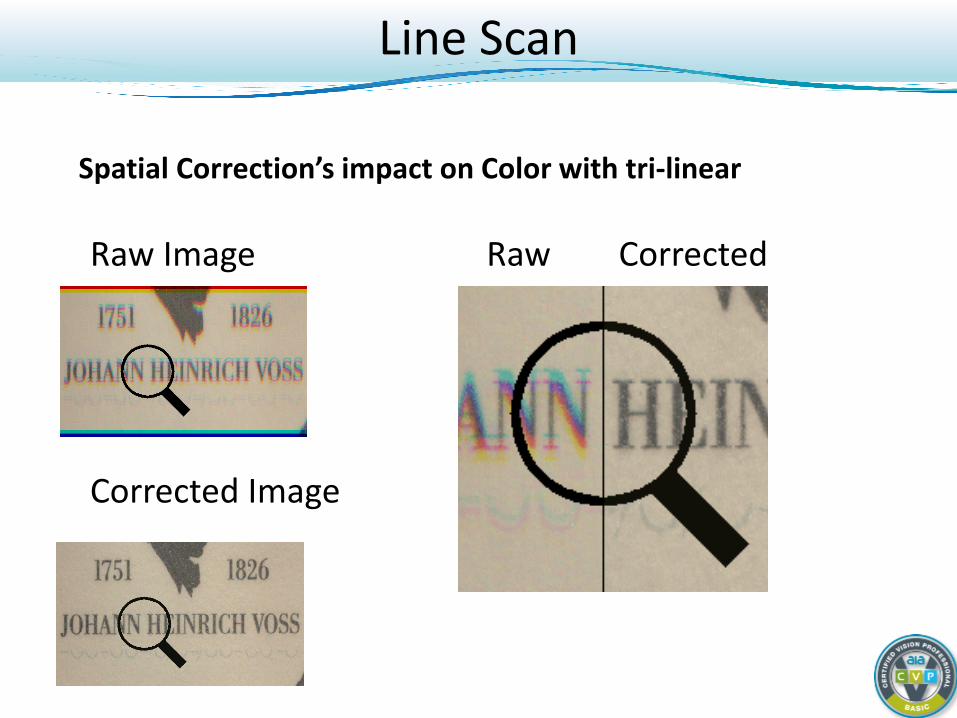
Raw Image Raw Corrected
Corrected Image
Spatial Correction’s impact on Color with tri-linear
Line Scan
CCD Sensor
Camera
Lens
Conveyer
Object
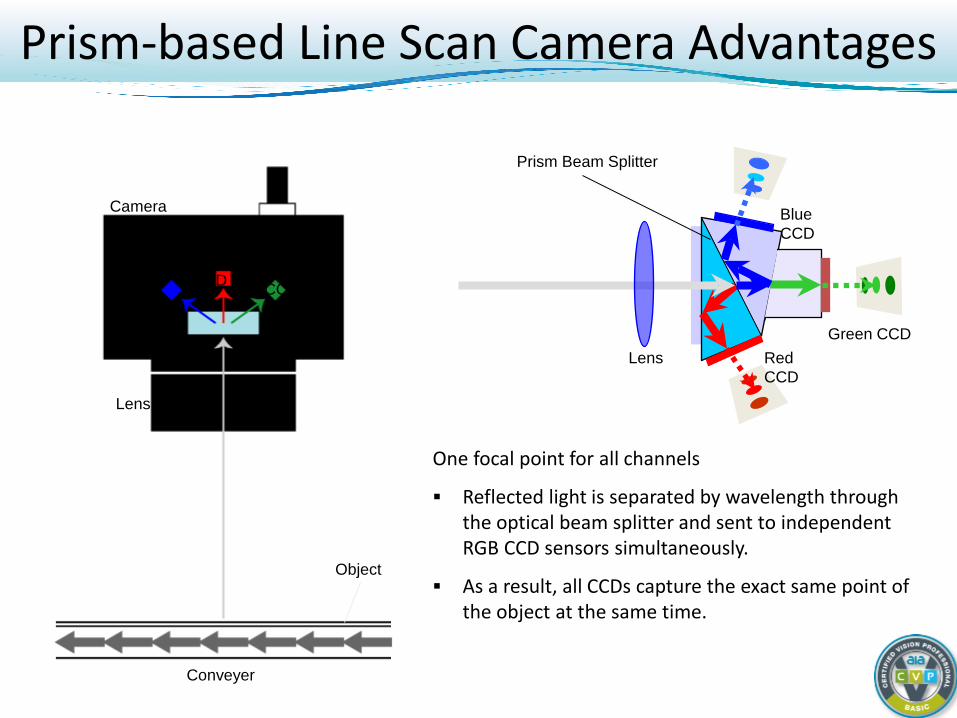
One focal point for all channels
Reflected light is separated by wavelength through the optical beam splitter and sent to independent RGB CCD sensors simultaneously.
As a result, all CCDs capture the exact same point of the object at the same time.
Red CCD
Camera
Lens
Conveyer
Object
Blue CCD
Green CCD
Prism
Prism Beam Splitter
Lens
Blue CCD
Green CCD Red CCD
Prism-based Line Scan Camera Advantages
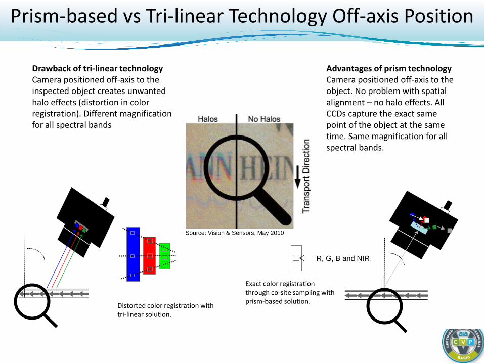
Prism-based vs Tri-linear Technology Off-axis Position
Drawback of tri-linear technology Camera positioned off-axis to the inspected object creates unwanted halo effects (distortion in color registration). Different magnification for all spectral bands
Advantages of prism technology Camera positioned off-axis to the object. No problem with spatial alignment – no halo effects. All CCDs capture the exact same point of the object at the same time. Same magnification for all spectral bands.
Distorted color registration with tri-linear solution.
Exact color registration through co-site sampling with prism-based solution.
Source: Vision & Sensors, May 2010
R, G, B and NIR
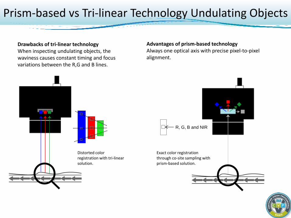
Prism-based vs Tri-linear Technology Undulating Objects
Drawbacks of tri-linear technology When inspecting undulating objects, the waviness causes constant timing and focus variations between the R,G and B lines.
Advantages of prism-based technology Always one optical axis with precise pixel-to-pixel alignment.
Distorted color registration with tri-linear solution.
R, G, B and NIR
Exact color registration through co-site sampling with prism-based solution.
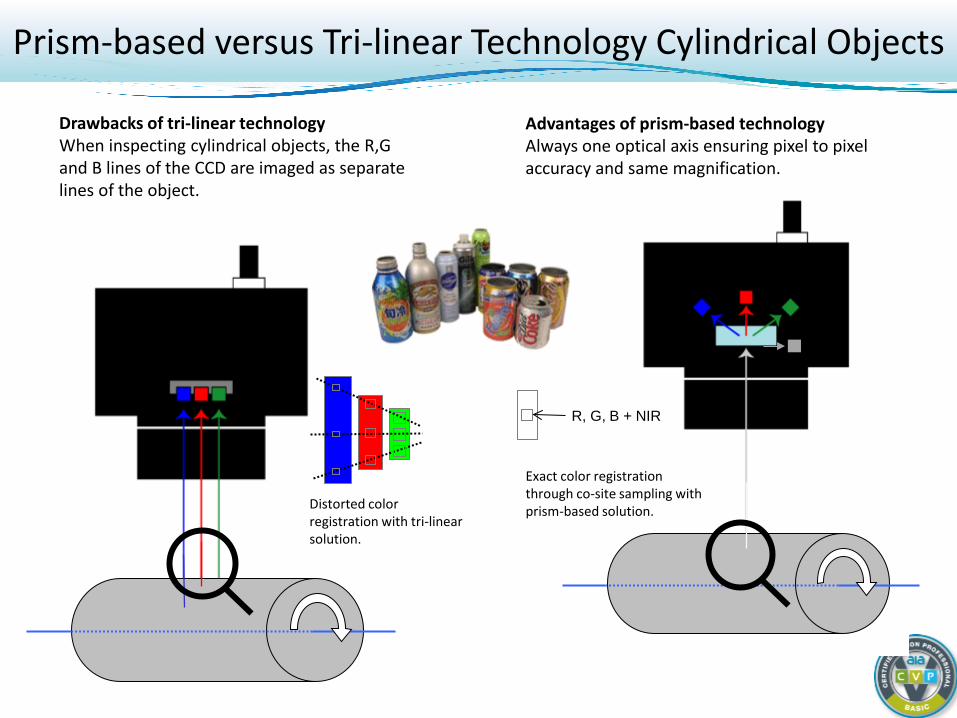
Prism-based versus Tri-linear Technology Cylindrical Objects
Drawbacks of tri-linear technology When inspecting cylindrical objects, the R,G and B lines of the CCD are imaged as separate lines of the object.
Advantages of prism-based technology Always one optical axis ensuring pixel to pixel accuracy and same magnification.
Distorted color registration with tri-linear solution.
R, G, B + NIR
Exact color registration through co-site sampling with prism-based solution.
Summary / Tips
Area Scan cameras are fairly straight forward. Line Scan requires more attention to alignment and
timing. Best color and spatial resolution come from 3-CCD
cameras. Tip: 80% of Machine Vision applications are probably
monochrome area scan. Area scan and Linescan applications rarely overlap.
When in doubt, prototype with area scan.
Basic Course Summary Frame rate and resolution are usually not enough to pick a camera. Use sensor performance, camera design, feature set, and cost-
effectiveness to narrow selection. Camera design can make or break image quality. No “one size fits all” interface. Remember to look at cabling, peripheral
cost, and scalability requirements. Area scan and Line scan should be viewed as two separate disciplines. Skill-
set, efficiency and cost vary greatly between the two.
Questions?
Contact Information
Jon Chouinard Sales Manager Baumer Ltd 122 Spring Street Southington CT USA Phone: +1 800 937 9336 Email: [email protected] LinkedIn: linkedin.com/in/jonathanchouinard Twitter: @jonchouinard www.baumer.com