The Fundamental Technology For Ultrasonic Cleaninginfohouse.p2ric.org/ref/25/24658.pdfI...
26
THE FUNDAMENTAL TECHNOLOGY FOR ULTRASONIC CLEANING
Transcript of The Fundamental Technology For Ultrasonic Cleaninginfohouse.p2ric.org/ref/25/24658.pdfI...

THE F U N D A M E N T A L TECHNOLOGY
FOR U L T R A S O N I C C L E A N I N G
I MISUNDERSTOOD ULTRASONIC CLEANING
1 What Is Ultrasonic Cleaning? (Its mechanism and characteristics)
It is indispensable f o r the solid understanding of CFC free
aqueous cleaning to define the fundamental mechanism of the
ultrasonic cleaning method.
Ultrasonic waves of more than 20kHz (compression waves) produce
cavities in liquid. When they implode, they produce impact force
(micro jet). This impact force is utilized for the ultrasonic
cleaning. Therefore it is essential to understand the fundamental
mechanism of cavitaion when you discuss ultrasonic cleaning since
this method is one of the applications of the impact force of
cavitaion, implosion of cavities produced-by ultrasonic waves. ~
Ultrasonic waves produced in liquid can not function for cleaning
unless they produce cavitation.
Following examples only produce bubbles not cavitation:
* ultrasonic bath
* ultrasonic face cleaner
* bubbles produced by air pump in a fish tank
* aeration of activated sludge tank
* ultrasonic face cleaner
Although ultrasonic waves could be detected with a modern detector
in the above examples, they are not actually utilized for cleaning.
Cleaning results can not be obtained only by compression waves.
Generation of cavitaion is indispensable for the ultrasonic cleaning
method.
1 -

'' 2 Misbelief of MHz
"Sound is compression waves of a .substance and the speed, Lf and
the acceleration, Cr are formulated as:
v = / A w l cos&
F = 1 ~ w t j sinwt , where V i s the frequency.
Therefore the higher frequency causes greater acceleration.
Acceleation is hundreds of thousands of times greater than the force
of gravity. MHz produces great cleaning end results because of its
huge acceleration of molecules."
Are the above sentences correct? The answer is NO.
Compression waves are the statistical energy density difference of
water molecules and do not define the direction of the movement.
Namely water molecules move random and can not be put in the same
direction; propagation of sound through the energy density change of
the molecule does not mean the transport nor the position change of
the molecule and does not produce any acceleration accordingly. So
you can not expect cleaning results from the movement of water
molecule with the huge acceleration.
It should be noticed that the wavelength(h) of the sound of 1 MHz
in water at normal temperature is about 1 . 5 mm, not in ,M m nor 1 units .
3 Core of Cavitation
Cavitaion core is mainly constituted of the gas of the medium.
- 2 -
.. The core varies according to energy difference between denseness and
non denseness and vapor pressure depending on the temperature of
liquid '(kinetic energy). Generally cavitation occurs in the liquid
with the higher steam pressure.
The cavitaion core in water is mainly constituted of water, but
the generation of core is heavily affected by the gas contained in
water as well as ions and impurities in water.
4 Shape of Cavity and Cavitation in Pure Water
When air is reduced to 0.5ppm in pure water, the shape of cavity
is linar or flat and the cavities implode in a zigzag line. The
core is considered to be constituted of water molecules.
5 Visualization of Cavitation
Cavitation core (cavity) can not be seen because of the high
frequency. However cavitation can be visualized with the aid of
luminescent material or by refraction of monochromatic light.
6 Elimination of Ultrasonic Waves
Air bubbles are the most effective factor to eliminate ultrasonic
waves in liquid. They block and absorb the most of the powerful
compression waves. Visible air bubbles result in restraing the
- 3 -
’ generation of cavitation. Therefore air bubbles in liquid are
adversary to ultrasonic cleaning.
Some of other adverse factors for the conventional ultrasonic
cleaning(the first generation) are;
* fine wire netting
* plastics, rubber
* turbulent flow
* dirty water, floating particles of dust
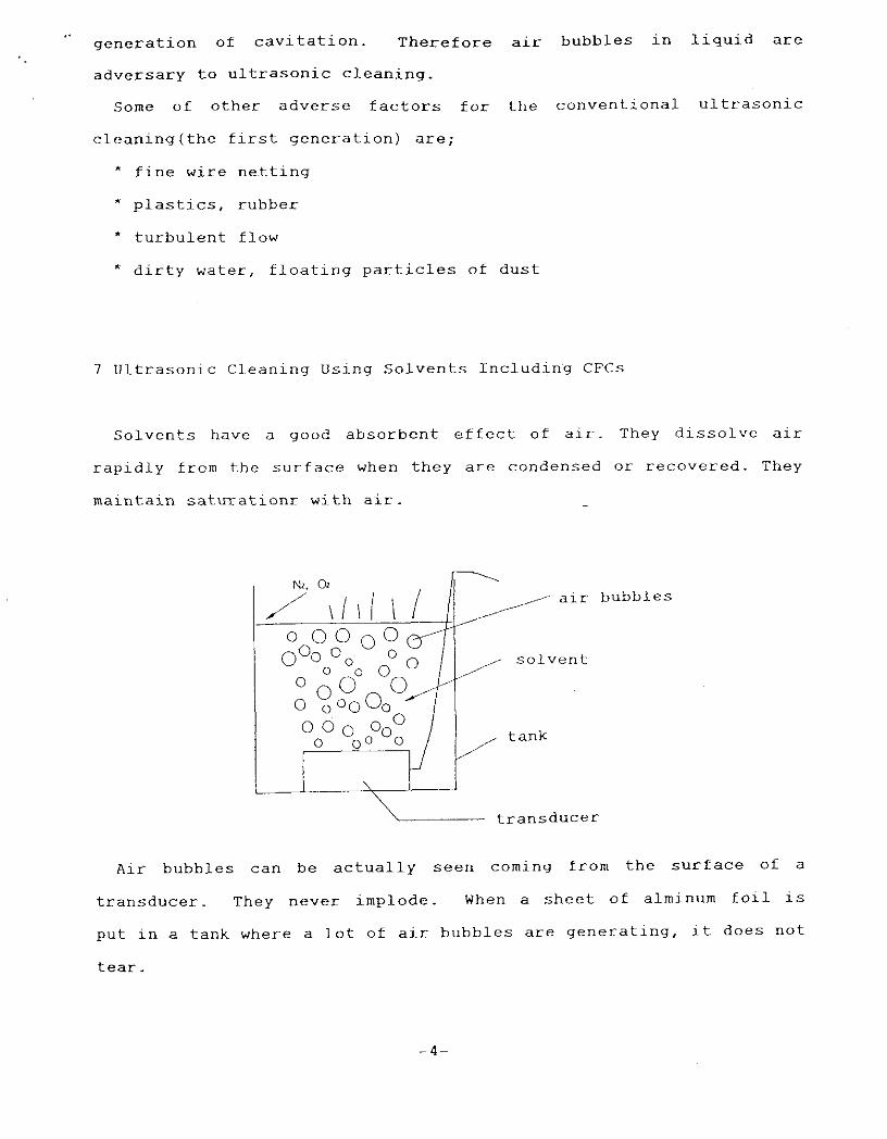
7 Ultrasonic Cleaning Using Solvents Including C F C s
Solvents have a good absorbent effect of alr. They dissolve alr
rapidly from the surface when they are condensed or recovered. They
maintain saturationr with air. ~
bubbles
transducer
Air bubbles can be actually seen coming from the surface of a
transducer. They never implode. When a sheet of alminum foil is
put in a tank where a lot of air bubbles are generating, it does not
tear.
- 4 -

As long as air bubbles generate (deaeration by ultrasonic waves)
and they eliminate ultrasonic waves most effectively, no cavitation
is achieved. Therefore no desired results is obtained by the
ultrasonic cleaning using chemicals including C F C - 1 1 3 , IPA,
ethylalcohol and chlorinated solvents such as 1 . 1 . 1 .
trichloroethane.
8 Easy Experiment for The Appropriate Ultrasonic Cleaning
water (Hz0)
tank ~
transducer
( 1 ) Run ultrasonic waves until air bubbles are gone.
(Stop running ultrasonic waves d s soon as cavitation makes
water turbid as air bubbles have dissappered.)
( 2 ) Put a sheet of alminum foil there.
( 3 ) Run ultrasonic waves for 60 sec. and watch how the alminum
foil change. You see it beginning to get torn.
To ensure the effective solvent used cleaning, air must be removed
from solvents including C F C s 1 - 1 . l . trichloroethane, alcohol and so forth.
The method of removing air does not use water but double
interfaces produced by temperature difference of liquid. It is
called the double interfacial method.
- 5
I1 B A S I C T E C H N I Q U E FOR U L T R A S O N I C C L E A N I N G
I C a v i t a t i o n C o n t r o l
U l t r a s o n i c c l e a n i n g is a me thod u s i n g a n i m p a c t f o r c e o f
c a v i t a t i o n p r o d u c e d by u l t r a s o n i c w a v e s . T h e r e f o r e p r o p e r c o n t r o l
o f c a v i t a t i o n is e s s e n t i a l f o r e n s u r i n g t h e e f f e c t i v e a n d s t a b l e
c l e a n i n g ; where a n d h o w c a v i t a i o n i s g e n e r a t e d .
C a v i t a i o n c o n t r o l i n v o l v e s t h e c o n t r o l o f l o c a t i o n , d e n s i t y and
i m p a c t f o r c e o f c a v i t a t i o n . T h i s is a n i n d i s p e n s i b l e t e c h n i q u e f o r
u l t r a s o n i c c l e a n i n g t o o b t a i n t h e g r e a t e r e f f e c i e n c y o f t h e
c a v i t a t i o n g e p e r a t i o n a n d a p p l i c a t i o n .
C l e a n i n g s y s t e m wh ich c a n a c h i e v e t h e p r o p e r c a v i . t a t i o n c o n t r o l is
q u a l i f i e d t o be c a l l e d " t h e u l t r a s o n i c c l e a n i n g s y s t e m o f t h e s e c o n d
g e n e r a t i o n " .
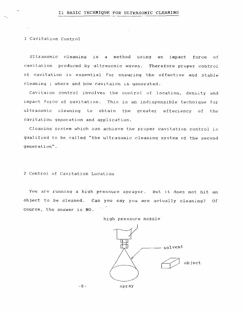
2 C o n t r o l . o f C a v i t a t i o n L o c a t i o n
You a r e r u n n i n g a h i g h p r e s s u r e s p r a y e r . B u t i t d o e s n o t h i t a n
o b j e c t t o be c l e a n e d . Can you s a y you a r e a c t u a l l y c l e a n i n g ? Of
c o u r c e , t h e a n s w e r is NO.
h i g h p r e s s u r e n o z z l e
6 - s p r a y
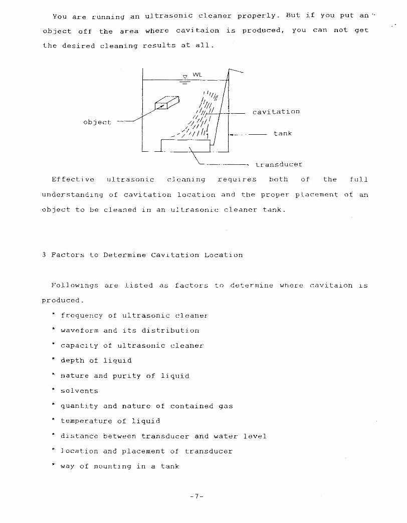
You are running an ultrasonic cleaner properly. But if YOU put a n ”
object o f f the area where cavitaion is produced, you can not get
the desired cleaning results at all.
object -
! I I
transducer
Effective ultrasonic cleaning requires both of the full
understanding of cavitation location and the proper placement of an
o b ~ e c t to be cleaned in an ultrasonic cleaner tank.
3 Factors to Determine Cavitation Location
Followings are listed as factors to determine where cavitaion is
produced.
* frequency of ultrasonic cleaner
* waveform and its distribution
* capacity of ultrasonic cleaner
* depth of liquid
* nature and purity o f liquid
* solvents
* quantity and nature of contained gas
* temperature of liquid
* distance between transducer and water level
* location and placement of transducer
* way of mounting in a tank
- 7 -

* shape of tank
* design conditions o f reflection surface
* temperature distribution of liquid
* turbulent flow or laminar flow boundary of liquid
* objects to be cleaned
* tools (wi.re netting , mesh belt, etc)
* cleaner's design conditions to cope with variety of liquids
and cleaning methods
* cleaner's design conditions to control dirt. stain ,
floating particles
* inaterial and surface condition of objects to be cleaned
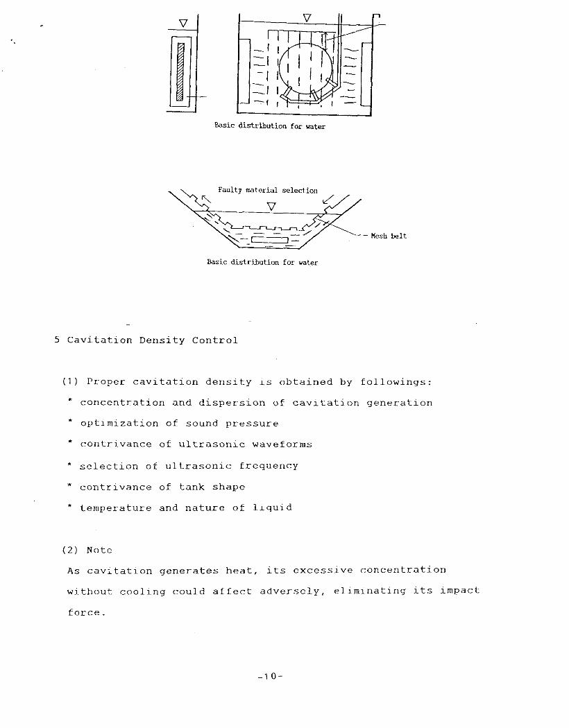
4 Basic Distribution
Understanding the basic distribution patterns of cavitation is
vital. Followings are the examples;
Vertical d i se jh t inn
lior-izontal distribution
Basic d i s t r ibu t ion for water
Grid d i s t r i b u t i o n
Basic dist r lbut ion Tar water - 8
Uniform d i s t r i h t i o r t7
I I
Basic distribution for water

Radiation ( d i r e c t )
Basic d i s t r i b u t i o o far water Basic d i s t r i b u t i o n for water
Column (cav i t a t ion ball)
V
Basic d i s t r i b u t i o n for water
( l a u l t y temperature s e t t i n g ) 1--+=[
k s i c d i s t r i b u t i o n for vatex
Cavi ta t ion ball in - deaera ted water
Basic d i s t r i b u t i o n for mter
"low &sic distribution tor water
Plar baske t des ign Object of c leaning h w efficiency
- -----.---I - ,\\ \ I / / /-
Basic d i r t r i b u t i a o for water Basic d i s t r i b u t i o n far water
-9-
I I Basic distribution far water
Oasic d i s t r i b u t i o n for water
5 Cavitation Density Control
( 1 ) Proper cavitation density is obtained by followings:
* concentration and dispersion of cavitation generation
* optimization of sound pressure
* contrivance of ultrasonic waveforms
* selection of ultrasonic frequency
* contrivance of tank shape
* temperature and nature of liquid
( 2 ) Note
As cavitation generates heat, its excessive concentratlon
without cooling could affect adversely, eliminating its impact
force .
1 0 -

6 Cavitation Impact Force Control
It 1s lmportant to optlmlze the impact force dependlng on an
oblect of cleaning.
( 1 ) General formula for Impact force
[liquid pressure] X [surface tenslon] X [other factors]
Impract force
[vapor pressure] X [frequency] X [contained g a s amouncl X [ o t h e r s ] 11
(liquid temperature)
( 2 ) Note
If you set a cleaner to obtain the maximum impact force with the
same energy, efficiency of cavitation becomes lower. Impact force
must be controlled to produce cavitation efficiently according to
an object of cleaning.
(3) Efficiency improvement of cavitation generation
Air contained in liquid is a key to obtain the efficient
utilization of ultrasonic waves. A s for water, it contains 6 - 8
ppm of oxgen at the normal temperature. Deaeration can not be
achieved only by running ultrasonic waves. On the contrary
running ultrasonic waves helps aeratlon from the surface and
results in being air saturated.
It is vital for the efficient ultrasonic cleaning to eliminate
or control the contents in solution. For this purpose we must
develop a method of blocking air coming in from the surface and
/or a deaeration system which enables deaeration faster than
dlssolution. A new system which achieves proper cavitaion
control, meeting the requirement mentioned above is called "the
reinforced aqueous cavitation system or the ultrasonic cleaning
method of the third generation".
-1 1 -
7 Basic Technique Regarding Waveforms
( 1 ) What is the most suitable form of ultrasonic waves for the
ultrasonic cleaning ?
O f cousre it is the one that creates the most desired cavitaion
for the specific cleaning. What we must realize here is that the
requied cavitation must be discussed with the relation to the type
of the cleaning object, the stains, the way of adhesion and the
system of cleaning. In a nut shell, it is useless to seek the
most suitable waveform for the multiple-use regardless of a
cleaning system and a cleaning object.
It is important to select the best ultrasonic cleaning system by
focusing on the characteristics of waveform, generation type and
so on.
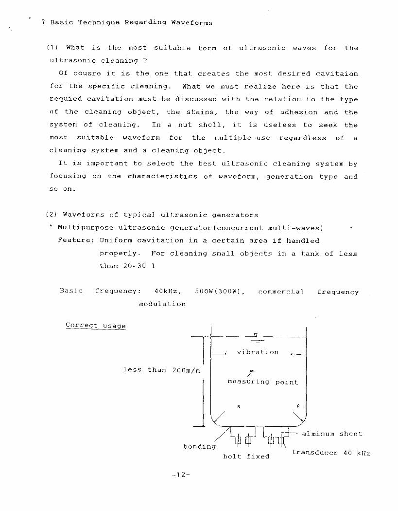
(2) Waveforms of typical ultrasonic generators
* Multipurpose ultrasonic generator(c0ncurrent multi-waves)
Feature: Uniform cavitation in a certain area if handled
properly. For cleaning small objects in a tank of less
than 20-30 1
Basic frequency: 40kHz. S O O W ( 3 0 0 W ) , commercial frequency
modulation
Correct usage - vibration +
-
m /
less than 200m/m
measuring point
R
alminum sheet / bonding
transducer 4 0 kHz bolt fixed
- 1 2 -
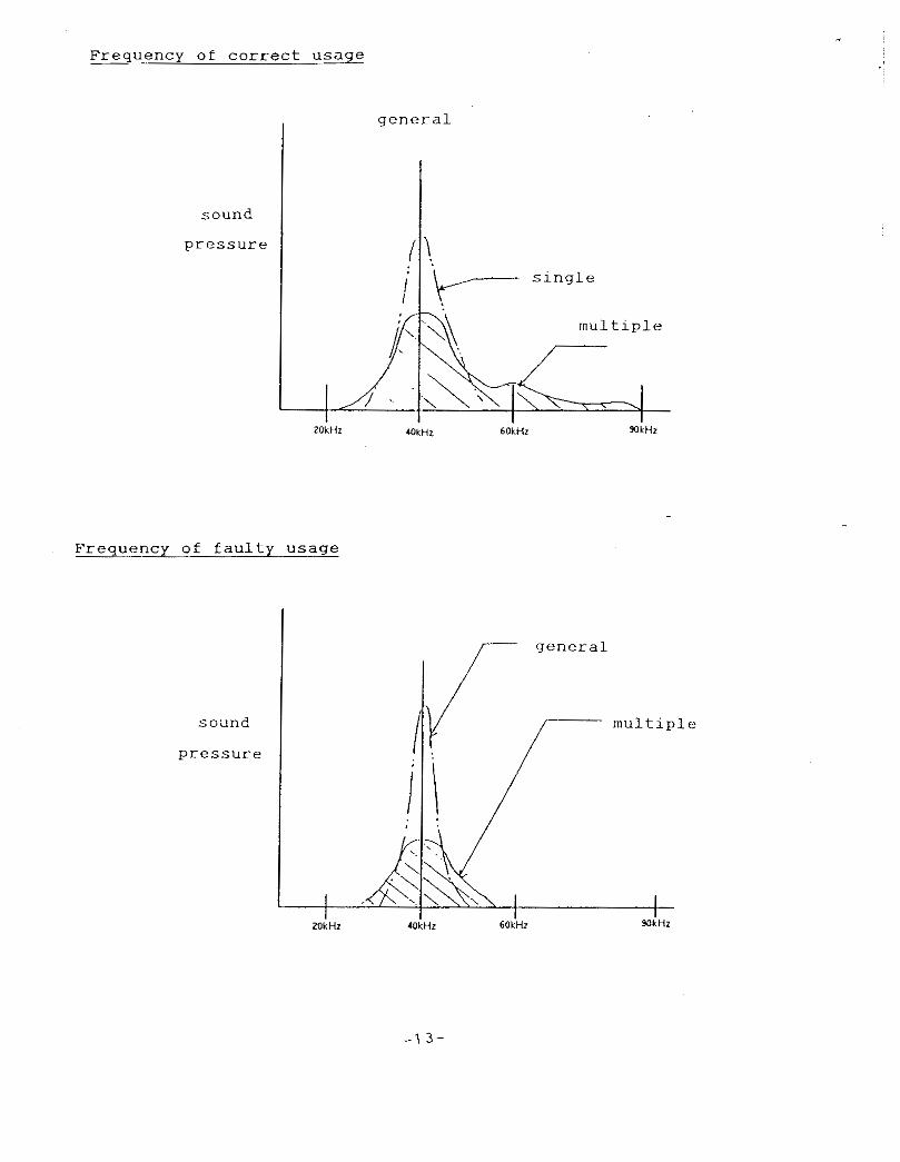
Frequency of c o r r e c t u s a g e
general I
m u l t i p l e
Frequency of f a u l t y u s a g e
-1 3-
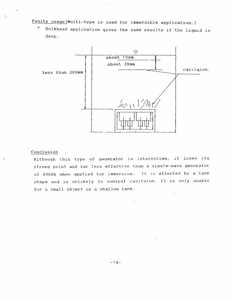
Faulty Usage(Mu1ti-type is used for immersible application.) * Bulkhead application gives the same results if the liquid is
deep.
less than
Conclusion
Although this type of generator is interesting, it loses its
strong point and far less effective than a single-wave generator
of 40kHz when applied for immersion. It is affected by a tank
shape and is unlikely to control cavitaion. It is only usable
for a small object in a shallow tank.
- 1 4 -
* Alternate multi-frequency system
Feature; Aiming to el.iminate standing waves by running a few
different kinds of ultrasonic waves of different
frequencies altenately.
Baic frequency; 28, 40, 60 kHz
Conclusion;.The system is possible in terms of idea. However it
is impossible to ensure the maximum amplitude for the different
frequencies, ),l, x2, and A 3 respectively while fixing the
temperature of liquid and transducer.
Correct application (if possible)
Note; Temperature of a transducer and liquid must be maintained
at the fixed temperature(norma1 temperature?).
Run 1 1 , A 2 and A3 simultaneously from the same transducer
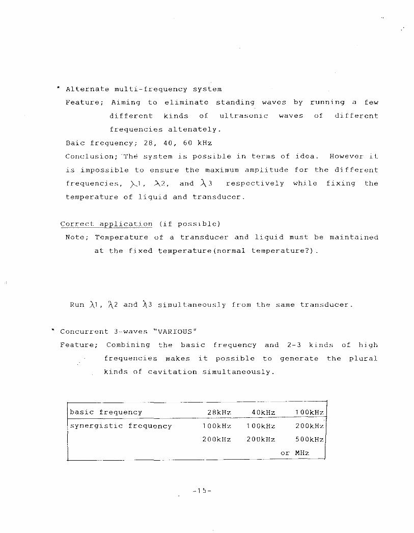
* Concurrent 3-waves "VARIOUS"
Feature; Combining the basic frequency and 2-3 kinds of high
frequencies makes it possible to generate the plural
kinds of cavitation simultaneously.
28kHz 40kHz 1 OOkHz
synergistic frequency 1 OOkHz 1 OOkHz 200kHz
200kHz 200kHz 500kHz
- 1 5-
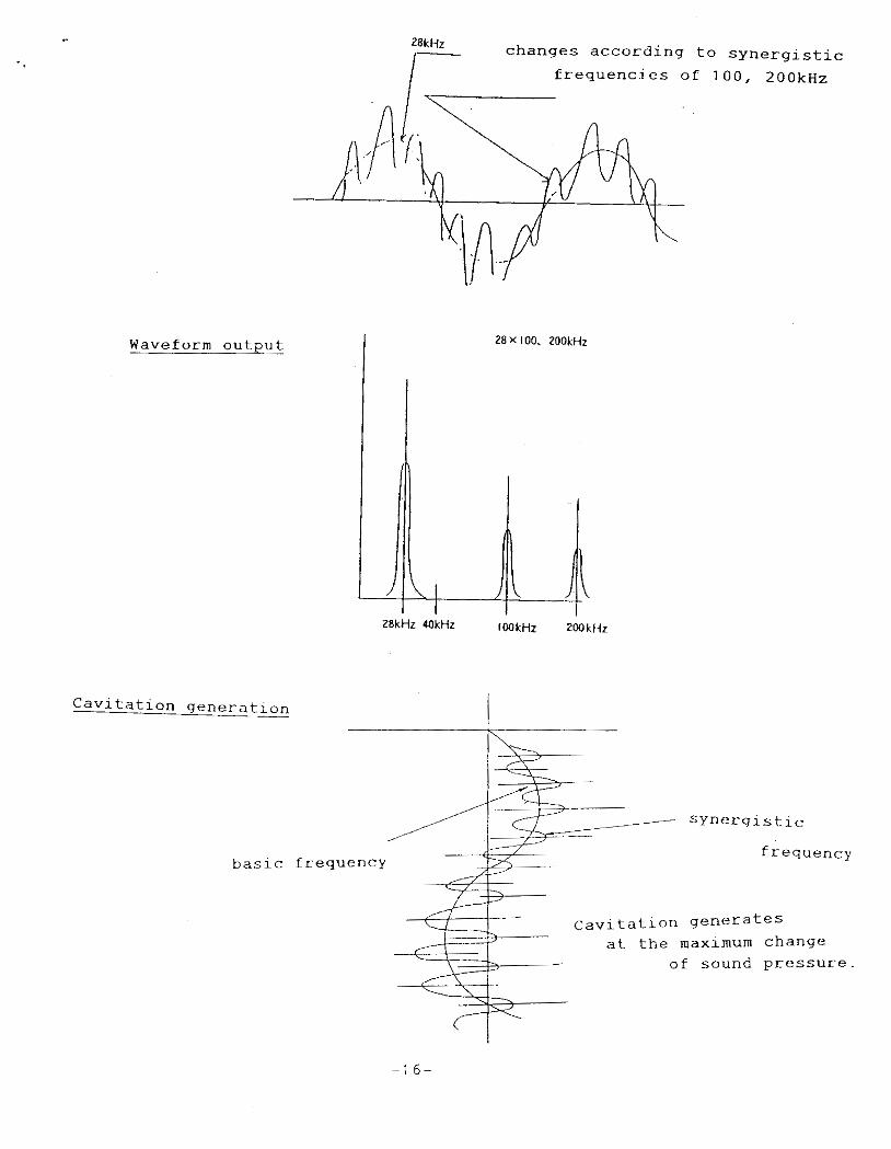
Waveform output
ZBkHz changes according to synergistic frequencies of 100, 2 0 0 k ~ ~
28X 100. 200kHz
2 Cavitation generation
basic frequency frequency
Cavitation generates at the maximum change
- of sound pressure.
1 6 -
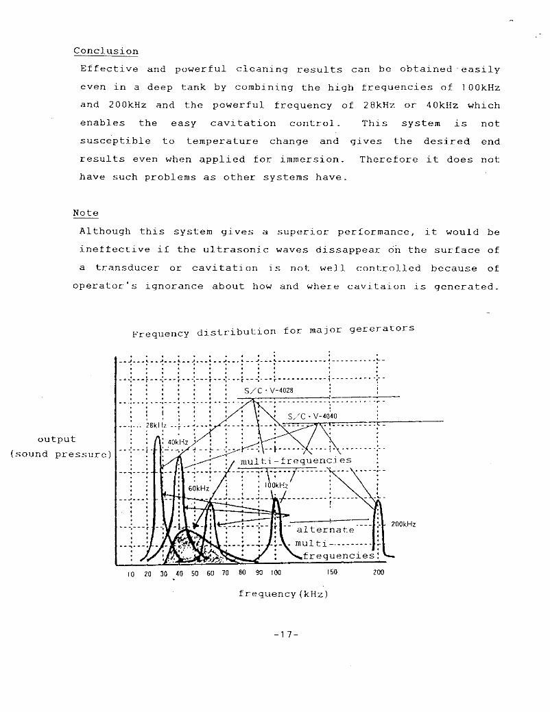
Conclusion
Effective and powerful cleaning results can be obtained 'easily
even in a deep tank by combining the high frequencies of l O O k H z
and ZOOkHz and the powerful frequency of 28kHz or 40kHz which
enables the easy cavitation control. This system is not
susceptible to temperature change and gives the desired end
results even when applied for immersion. Therefore it does not
have such problems as other systems have.
Note ~
Although this system gives a superior performance, it would be
ineffective if the ultrasonic waves dissappear on the surface of
a transducer or cavitation is not well controlled because of
operator's ignorance about how and where cavltaion is generated.
output (sound p r e s s u r e )
- 1 7 -
General principle for the powerful aqueous cleaning
To utilize ultrasonic waves -efficiently, cavitation should be
controlled by maintaing dissolved oxygen vaulue under 2 ppm.
- 1 8-

I11 REINFORCED AQUEOUS CLEANING SYSTEM - BASIC TECHNIQUE
1 New Viewpoint of The Ultrasonic Cleaning Technology
When running ultrasonic waves in liquid, what are the requirements
for the best liquid to propagate ultrasonic waves and create the
desired cavitation most efficiently?
2 Dependence on The Quali.ty of The Liquid
Cleaning performance depends on cavitation. The nature of: the
generated cavitation varies according to the purity of the liquid
and the amount of the dissolved air. Furthermore the optimum depends
on an object of cleaning and the quality of oil. A s for aqueous
system, it would be reasonable to classify water based on 5 levels
of purity and 5 levels o f dissolved air as follows, which gives 25
kinds of water.
(Variety of purity)
* water containing detergent
* tap water
* p u r e water l e s s than 2 M&/cm
* pure water 2 - 5 ~ a / c m
* p u r e water more than 5Ma/cm
(Variety of dissolved oxygen)
* water of DO value 6-8ppm
4-6ppm "
-1 9 -

.- * water of DO value Z - ~ P P ~
f 0.5-2ppm
" less than O.5ppm
a ,
I
The ultrasonic cleaning of the third generation or reinforced
cavitaion system utilizes ultrasonic waves most effectively by
focusing on the quality of liquid, more specifically purity and
dissolved oxygen of liquid. Conventional ultrasonic cleaning
systems utilize partially the capacity of ultrasonic waves.
3 Example of Controlling Dissolved Oxgen in Tap Water(referred to as
DO below)
cooler
Note; Reinforced module is for deaeration.. The design varies
according to liquid such as water, alcohol, pure water, light oil,
etc.
- 2 0 -

.. 4 General Principle of Reinforced Aqeous Cleaning System
To make best u s e of the energy of ultrasonic waves f o r the
generation of cavitation It is vital to control DO value under 2
ppm .
( 1 ) How to know the DO value from the surface condition
( S It C ’ s cleaner: 600W. 28kHz X 100 200kHz. depth; 200”
water; RT)
Observation - DO ( p p m ) .~ ~
6-8 Small, smooth and round swells appear sometimes on the
water surface. Tiny bubbles like white smoke come out
of the surface of a transducer.
BAD - - _ _ - - _
4 - 6 Small and round swells keep coming out for a long
period. Tiny waves appear on some part of the surface.
BAD - _ _ _ _ _ -
2-3 Tiny waves appear on the entlre surface. A
interference pattern of lOOkIiz and 200kHz is observed
Round swells come out occassionaly on a part of the
s u r f ace.
GOOD - - - - - - -
0.5-2 A fine interference pattern is observed on the entire
surface. No round swells appear. Occasional fine
spray is observed.
VERY GOOD - - - - -
- 2 1 -
I .
Note: Recent study shows the close llnk between DO value and
emulsification. A s for emulsifacatlon independantly.
than 1 5 ppm of supersaturation gives the good results.
value control must be studied in the wide range; under
’ . more
DO
G.Sppm, several ppm, and up to 20 ppm of supersaturation
Yet the value under 2 ppm is ideal for the reinforced
cavitation .
( 2 ) Visible evidences for bad cleaning by reinforced cavitation
system
* Visible tiny bubbles in liquid Especially bubbles to be seen at
the moment of turning off the machine
* Round swell on the water surface caused by visible tiny bubbles
* Smoke like tiny bubbles from the surface of a transducer
(Before this condition was considered-to be an evidence for gdod
cleaning.)
* Screechy sound of low frequency (mis-control of cavitation)
* No waveform to be seen (Ultrasonic waves do not reach the surface
even if there are no objects of cleaning in the tank. Peculiar
waveform of the transducer maker should be observed on the
surf ace.
( 3 ) Visible evidences for the defective design of the cleaner
A waveform seen on the surface varies according to the maker of a
transducer. Therfore it is the simple and easy measure for the
judgement of the cleaner’s function to see whether the maker’s
peculiar waveform appears on the entire surface without putting a
cleaning object. If the waveform is not observed, it means
ultrasonic waves dissapear before reaching the surface. A multi-
wave generator creates a interference pattern of 40-60(9G)kHz.
2 2-
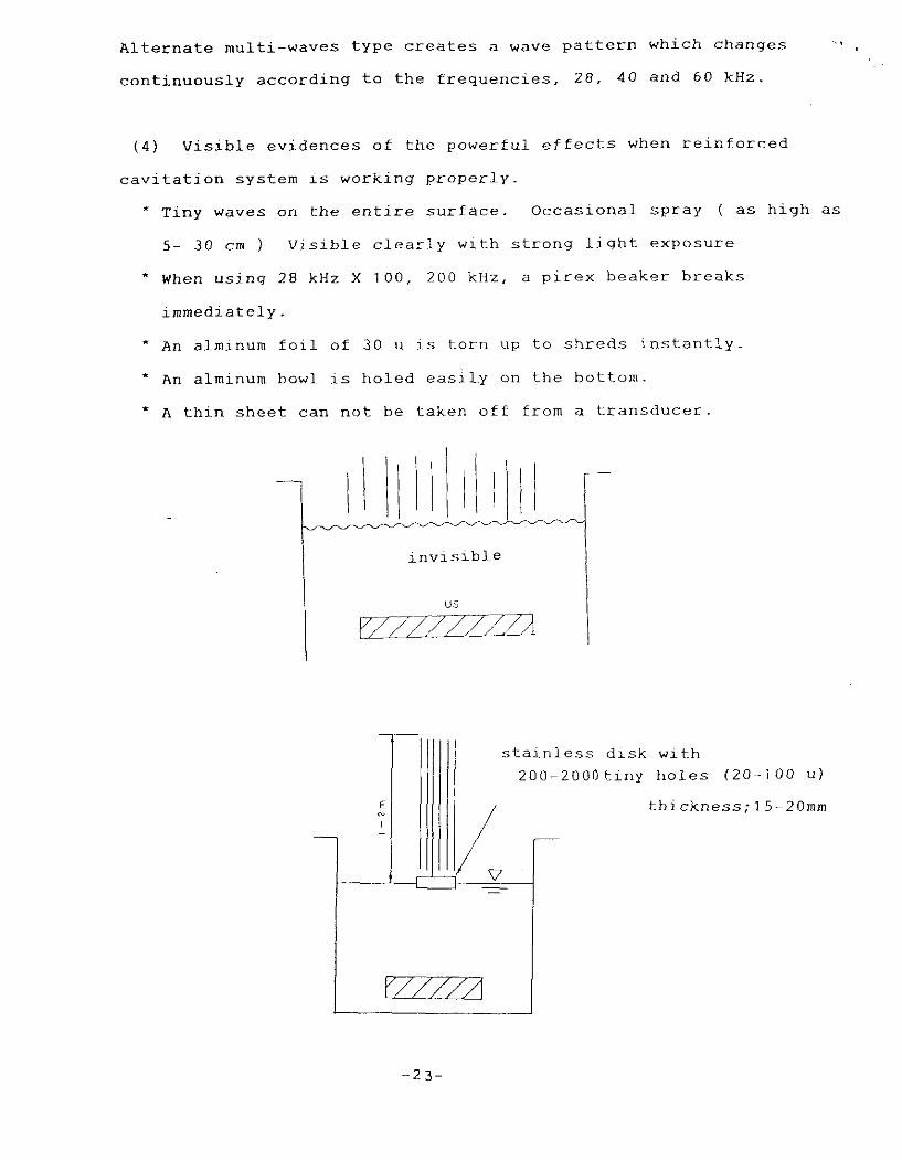
, % Alternate multi-waves type creates a wave pattern which changes
continuously according to the frequencies, 2 8 , 4 0 and 60 kHz.
( 4 ) Visible evidences of the powerful effects when reinforced
cavitation system is working properly.
Tiny waves on the entire surface. Occasional spray ( as high a s
5- 3 0 cm ) Visible clearly with strong light exposure
* When using 28 kHz X 1 0 0 , 2 0 0 kHz, a plrex beaker breaks
immediately.
* An alminum f o i l of 30 u is torn up to shreds instantly.
* An alminum bowl is holed easily on the bottom.
* A thin sheet can not be taken of€ from a transducer.
invisible
US
stainless disk with 200-2000tiny holes ( 2 0 - 1 0 0 u )
- 2 3 -

.. CFC Free Aqueous Cleaning Technology Incorporated with Reinforced
Cavitation System
Water has cleaned the earth and everything on it for four bil.lion
and some hundred million years after its birth. The life was born
in water. Since then water has been utilized as the harmless and
special liquid for cleaning. To take great advantage of water as
the better cleaning agent, studies must be carried out by focusing
on the nature of the various kinds of liquid in terms of their
application to the new ultrasonic technology. The reinforced
cavitation system opened the new era of the ultrasonic cleaning
technology of the third generation.
Manufacturer S & C CO., LTD
liead office 4087-1, Aikawa-clio, Nakatsu, Aikoh-gun, Kanagawa 243 Phone 0462-86-2779(Rep) Facsimile 0424-86-5709
- 2 4-

..